conforming to osha standard pressure relief 3 port … step2 combination with a (modular style)...
TRANSCRIPT
Step1
Step2
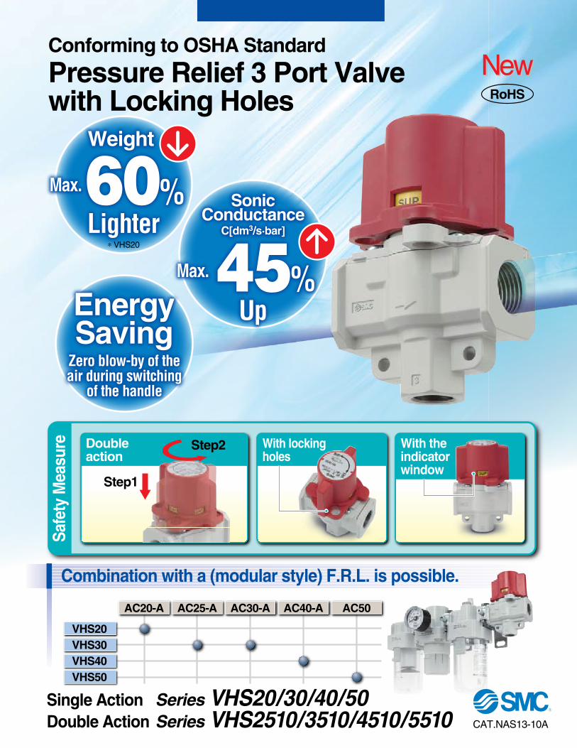
Combination with a (modular style) F.R.L. is possible.
AC20-A AC25-A AC30-A AC40-A AC50
VHS20VHS30VHS40VHS50
Zero blow-by of theair during switching
of the handle
EnergySaving
Doubleaction
With theindicatorwindow
Safe
ty M
easu
re With lockingholes
VHS20
60%Lighter
Weight
Max.
45%Up
SonicConductance
C[dm3/s·bar]
Max.
CAT.NAS13-10A
Single Action Series VHS20/30/40/50Double Action Series VHS2510/3510/4510/5510
Conforming to OSHA Standard
Pressure Relief 3 Port Valvewith Locking Holes
NewNewRoHS

Material: Resin (Handle, bonnet)
With the indicator window
With locking holes
With bracket Built-in silencer (EXH port)
Double action
Lightweight Options
Made to Order(-X1)
Variations
Safety Measure
OSHA standard (Occupational Safety and Health Administration Department of Labor)For safety control, OSHA rule requires energy sources for certain equipment be turned off or disconnected and that the device either be locked or labelled with a warning tag.
: SupplySUP : ExhaustEXH
Bracket
Step1Push down the handle
Turn the handle
Step2
Can prevent accidents caused by inadvertent air supply problems.
Red body is available.
VHS20 (Aluminum body is standard): 190 g
76 g
VHS20- AVHS20- B
Single Action Series VHS20/30/40/50Double Action Series VHS2510/3510/4510/5510
Handle: Flame resistant PBT(Equivalent to UL-94,V-0)
Bonnet: Flame resistant PBT(Equivalent to UL-94,V-0)
Built-insilencer
Silencer can bemounted
afterwards
Body: Aluminum
Aluminum handle and bonnet type is available.
1/8
1/4
3/8
1/2
3/4
1
VHS2510 VHS3510 VHS4510 VHS5510Double action
VHS20 VHS30 VHS40 VHS50Single action
Element
Elementcover
Resin handle and bonnet is standard. 60% Lighter
Space saving
Body
WeightMaximum
Port size 1/8, 1/4, and 3/8 are now available for double action type.
The supply/exhaust status of the air flow can be verified at a glance in the indicator window.
When in the exhaust position, the valve may be padlock secured. Prevents accidental start-ups while personnel are cleaning or servicing equipment.
Push the handle and then turn, 2-step action prevents malfunction.
Features 1 Features 2
Conforming to OSHA Standard
Pressure Relief 3 Port Valve with Locking Holes

IN OUT
Built-in silencer
3
Spacer
Spacer with bracket
Conforming to OSHA Standard
Pressure Relief 3 Port Valvewith Locking Holes (Single Action)
Series VHS20/30/40/50How to Order
04 A BSVHS 40Made to Order
X1Description
Body: Red Note)
Symbol
Semi-standard specifications
NilR
Z Note)
Description—
Flow direction: Right LeftPSI as unit displayed on label
Symbol
Options
NilB
S
Description
—
With bracket
Built-in silencer (EXH port)
Symbol
Pressure relief 3 port valve
Body size
20304050
SymbolThread type
NilNF
RcNPT
G
Note) Only for the NPT thread. Under the New Measurement Law, products for overseas use only (SI unit type for use in Japan).
Note) Refer to Photo of X1 in Feature 2 for the appearance.
Note) VHS50 can be connected to AC55 and AC60.
Handle / Bonnet material
AB
MaterialFlame resistant PBT
Aluminum
Symbol
010203040610
SymbolBody size
20
————
30—
———
40—
—
50————
Port size
Port size
1/81/43/81/23/41
Pressure relief 3 port valve Spacer with bracket part no.Spacer part no.Y200-AY300-AY400-AY500-AY600-A
Y200T-AY300T-AY400T-AY500T-AY600T-A
Applicable air preparation equipmentAC20-AAC25-A, AC30-AAC40-AAC40-06-AAC50, AC55 Note), AC60 Note)
VHS20VHS30VHS40VHS40-06VHS50
Single action
A spacer or spacer with bracket is required if the valve is combined with modular F.R.L. Please order it separately.VHS type can be ordered from How to Order of modular F.R.L. combination.
1
RoHS
EXH
IN OUT
3 (EXH)
1 (IN) 2 (OUT)
Cross section of EXH port
Built-in silencer(Option)
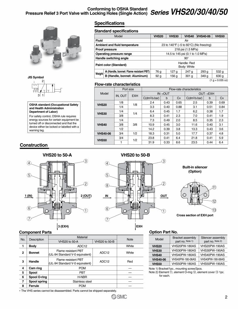
Model VHS20 VHS30 VHS40 VHS40-06 VHS50
76 g92 g
127 g156 g
247 g301 g
293 g349 g
532 g630 g
Air23 to 140°F (–5 to 60 C) (No freezing)
218 psi (1.5 MPa)14.5 to 145 psi (0.1 to 1.0 MPa)
90
Handle: RedBody: White
FluidAmbient and fluid temperatureProof pressureOperating pressure rangeHandle switching angle
Paint color (Standard)
Weight
ModelIN, OUT EXH
Port sizeIN OUT OUT EXH
Flow-rate characteristics
C(dm3/s·bar) b Cv C(dm3/s·bar) b Cv1/81/41/43/81/43/81/23/43/41
2.4 3.3 6.4 8.3 7.310.914.218.323.831.9
0.430.400.450.410.490.450.390.310.410.33
0.650.881.7 2.3 2.0 3.0 3.8 5.0 6.4 8.6
2.5 3.1 6.2 7.0 8.511.613.317.721.823.5
0.390.510.380.410.350.400.430.370.410.44
0.690.841.7 1.9 2.3 3.1 3.6 4.8 5.9 6.4
1/8
1/4
3/8
1/2
1/2
VHS20
VHS30
VHS40
VHS40-06
VHS50
Component Parts
Flow-rate characteristics
Standard specifications
DescriptionVHS20 to 50-A VHS20 to 50-B
Material
Flame resistant PBT(UL-94 Standard V-0 equivalent)
Flame resistant PBT(UL-94 Standard V-0 equivalent)
ADC12
ADC12
ADC12
POMPBT
H-NBRStainless steel
POM
Note
White
White
Red
—————
Body
Bonnet
Handle
Cam ringSpoolSpool O-ringSpool springFerrule
No.
1
2
3
45678
The VHS series cannot be disassembled. Parts cannot be shipped separately.
Note 1) Bracket/1pc., mounting screw/2pcs.Note 2) Element , element O-ring , element cover 1pc.
for each.
Specifications
Construction
VHS20 to 50-BVHS20 to 50-A
JIS Symbol
OSHA standard (Occupational Safety and Health Administration Department of Labor)
For safety control, OSHA rule requires energy sources for certain equipment be turned off or disconnected and that the device either be locked or labelled with a warning tag.
3 1
2
A (Handle, bonnet: Flame resistant PBT)B (Handle, bonnet: Aluminum)
Option Part No.
VHS20PW-180ASVHS30PW-180ASVHS40PW-180ASVHS40PW-180-06ASVHS50PW-180AS
VHS20PW-190ASVHS30PW-190ASVHS40PW-190ASVHS40PW-190-06ASVHS50PW-190AS
Model
VHS20VHS30VHS40VHS40-06VHS50
Bracket assemblypart no. Note 1)
Silencer assemblypart no. Note 2)
(1 g = 0.035 oz)
2
Series VHS20/30/40/50Conforming to OSHA StandardPressure Relief 3 Port Valve with Locking Holes (Single Action)
EXH
IN OUT
3 (EXH)
1 (IN) 2 (OUT)
Cross section of EXH port
Built-in silencer(Option)
Model VHS20 VHS30 VHS40 VHS40-06 VHS50
76 g92 g
127 g156 g
247 g301 g
293 g349 g
532 g630 g
Air23 to 140°F (–5 to 60 C) (No freezing)
218 psi (1.5 MPa)14.5 to 145 psi (0.1 to 1.0 MPa)
90
Handle: RedBody: White
FluidAmbient and fluid temperatureProof pressureOperating pressure rangeHandle switching angle
Paint color (Standard)
Weight
ModelIN, OUT EXH
Port sizeIN OUT OUT EXH
Flow-rate characteristics
C(dm3/s·bar) b Cv C(dm3/s·bar) b Cv1/81/41/43/81/43/81/23/43/41
2.4 3.3 6.4 8.3 7.310.914.218.323.831.9
0.430.400.450.410.490.450.390.310.410.33
0.650.881.7 2.3 2.0 3.0 3.8 5.0 6.4 8.6
2.5 3.1 6.2 7.0 8.511.613.317.721.823.5
0.390.510.380.410.350.400.430.370.410.44
0.690.841.7 1.9 2.3 3.1 3.6 4.8 5.9 6.4
1/8
1/4
3/8
1/2
1/2
VHS20
VHS30
VHS40
VHS40-06
VHS50
Component Parts
Flow-rate characteristics
Standard specifications
DescriptionVHS20 to 50-A VHS20 to 50-B
Material
Flame resistant PBT(UL-94 Standard V-0 equivalent)
Flame resistant PBT(UL-94 Standard V-0 equivalent)
ADC12
ADC12
ADC12
POMPBT
H-NBRStainless steel
POM
Note
White
White
Red
—————
Body
Bonnet
Handle
Cam ringSpoolSpool O-ringSpool springFerrule
No.
1
2
3
45678
The VHS series cannot be disassembled. Parts cannot be shipped separately.
Note 1) Bracket/1pc., mounting screw/2pcs.Note 2) Element , element O-ring , element cover 1pc.
for each.
Specifications
Construction
VHS20 to 50-BVHS20 to 50-A
JIS Symbol
OSHA standard (Occupational Safety and Health Administration Department of Labor)
For safety control, OSHA rule requires energy sources for certain equipment be turned off or disconnected and that the device either be locked or labelled with a warning tag.
3 1
2
A (Handle, bonnet: Flame resistant PBT)B (Handle, bonnet: Aluminum)
Option Part No.
VHS20PW-180ASVHS30PW-180ASVHS40PW-180ASVHS40PW-180-06ASVHS50PW-180AS
VHS20PW-190ASVHS30PW-190ASVHS40PW-190ASVHS40PW-190-06ASVHS50PW-190AS
Model
VHS20VHS30VHS40VHS40-06VHS50
Bracket assemblypart no. Note 1)
Silencer assemblypart no. Note 2)
(1 g = 0.035 oz)
2
Series VHS20/30/40/50Conforming to OSHA StandardPressure Relief 3 Port Valve with Locking Holes (Single Action)

M
W
T
XY
VU
Bracket(Option)
P2(Port size)
2 x P1(Port size)
2
øI
FGH
E
C
ø10
DPadlock mounting position
L
RS
Q
N
AB
EXH
IN OUT
SUP
3
3
J
2 x øK
AA
Built-in silencer(Option)
BB(Width across flats)
EXH.
SUP.
312
EXH.
SUP.
EXH.
SUP.
312
312
Dimensions
Dimensions
ModelP1 P2 A B C D E F G H I J K L M
1/8, 1/41/4, 3/8
1/4, 3/8, 1/23/4
3/4, 1
1/81/43/81/21/2
66.4 80.3104.9110.4134.3
22.329.438.54253
4053707590
37.549636376
1419222226
46.652585876
33.638444461
2830364453
37.549636381
2430384350
4.54.55.55.56.5
14.819242631
9 9101012
(mm)
VHS20VHS30VHS40VHS40-06VHS50
Standard specifications
Model Built-in silencer
N Q R S T U V W X Y AA2.32.32.82.83.2
3041505070
53.3677979
108
25.333444660
31.340535571
75.4 90.9119.4123.4152.3
4053707090
2736.543.543.549.5
8.410191927.5
5.4 6.5 8.5 8.511
33344
BB1214192222
VHS20VHS30VHS40VHS40-06VHS50
With bracketOptions specifications
VHS30
VHS40/50
VHS20
3
Series VHS20/30/40/50
IN OUT
Spacer with bracket
Spacer
Spacer with bracket
Built-in silencer
3
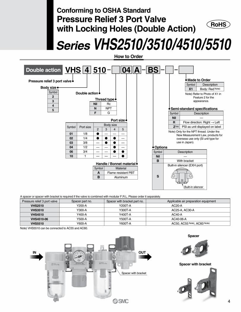
How to Order
04 A BSVHS 4Made to Order
X1Description
Body: Red Note)
Symbol
Semi-standard specifications
NilR
ZNote)
Description—
Flow direction: Right LeftPSI as unit displayed on label
Symbol
Options
NilB
S
Description—
With bracketBuilt-in silencer (EXH port)
Symbol
Pressure relief 3 port valve
510
Double action
Body size
Thread typeNilNF
RcNPT
G
Handle / Bonnet material
010203040610
SymbolBody size
2
————
3—
———
4—
—
5————
Port size
Port size
1/81/43/81/23/41
Double action
2345
Symbol
AB
MaterialFlame resistant PBT
Aluminum
Symbol
Note) VHS5510 can be connected to AC55 and AC60.
A spacer or spacer with bracket is required if the valve is combined with modular F.R.L. Please order it separately.
Pressure relief 3 port valve Spacer with bracket part no.Spacer part no.Y200-AY300-AY400-AY500-AY600-A
Y200T-AY300T-AY400T-AY500T-AY600T-A
Applicable air preparation equipmentAC20-AAC25-A, AC30-AAC40-AAC40-06-AAC50, AC55 Note), AC60 Note)
VHS2510VHS3510VHS4510VHS4510-06VHS5510
Note) Refer to Photo of X1 in Feature 2 for the appearance.
Note) Only for the NPT thread. Under the New Measurement Law, products for overseas use only (SI unit type for use in Japan).
Conforming to OSHA StandardPressure Relief 3 Port Valvewith Locking Holes (Double Action)
Series VHS2510/3510/4510/5510
4
RoHS
IN OUT
Spacer with bracket
Spacer
Spacer with bracket
Built-in silencer
3
How to Order
04 A BSVHS 4Made to Order
X1Description
Body: Red Note)
Symbol
Semi-standard specifications
NilR
ZNote)
Description—
Flow direction: Right LeftPSI as unit displayed on label
Symbol
Options
NilB
S
Description—
With bracketBuilt-in silencer (EXH port)
Symbol
Pressure relief 3 port valve
510
Double action
Body size
Thread typeNilNF
RcNPT
G
Handle / Bonnet material
010203040610
SymbolBody size
2
————
3—
———
4—
—
5————
Port size
Port size
1/81/43/81/23/41
Double action
2345
Symbol
AB
MaterialFlame resistant PBT
Aluminum
Symbol
Note) VHS5510 can be connected to AC55 and AC60.
A spacer or spacer with bracket is required if the valve is combined with modular F.R.L. Please order it separately.
Pressure relief 3 port valve Spacer with bracket part no.Spacer part no.Y200-AY300-AY400-AY500-AY600-A
Y200T-AY300T-AY400T-AY500T-AY600T-A
Applicable air preparation equipmentAC20-AAC25-A, AC30-AAC40-AAC40-06-AAC50, AC55 Note), AC60 Note)
VHS2510VHS3510VHS4510VHS4510-06VHS5510
Note) Refer to Photo of X1 in Feature 2 for the appearance.
Note) Only for the NPT thread. Under the New Measurement Law, products for overseas use only (SI unit type for use in Japan).
Conforming to OSHA StandardPressure Relief 3 Port Valvewith Locking Holes (Double Action)
Series VHS2510/3510/4510/5510
4
RoHS

3 (EXH)3 (EXH)
1 (IN) 2 (OUT)2 (OUT)1 (IN)
Cross section of EXH port
Built-in silencer(Option)
Specifications
Model VHS2510 VHS3510 VHS4510 VHS4510-06 VHS5510
77 g93 g
129 g158 g
250 g304 g
296 g352 g
536 g635 g
Air23 to 140°F (–5 to 60 C) (No freezing)
218 psi (1.5 MPa)14.5 to 145 psi (0.1 to 1.0 MPa)
90
Handle: RedBody: White
FluidAmbient and fluid temperatureProof pressureOperating pressure rangeHandle switching angle
Paint color (Standard)
WeightA (Handle, bonnet: Flame resistant PBT)B (Handle, bonnet: Aluminum)
ModelIN, OUT EXH
Port sizeIN OUT OUT EXH
Flow-rate characteristics
C(dm3/s·bar) b Cv C(dm3/s·bar) b Cv1/81/41/43/81/43/81/23/43/41
2.4 3.3 6.4 8.3 7.310.914.218.323.831.9
0.430.400.450.410.490.450.390.310.410.33
0.650.881.7 2.3 2.0 3.0 3.8 5.0 6.4 8.6
2.5 3.1 6.2 7.0 8.511.613.317.721.823.5
0.390.510.380.410.350.400.430.370.410.44
0.690.841.7 1.9 2.3 3.1 3.6 4.8 5.9 6.4
VHS2510
VHS3510
VHS4510
VHS4510-06
VHS5510
Flow-rate characteristics
Standard specifications
Construction
VHS2510 to 5510-BVHS2510 to 5510-A
1/8
1/4
3/8
1/2
1/2
JIS Symbol
3 1
2
Component Parts
DescriptionVHS2510 to 5510-A VHS2510 to 5510-B
Material
Flame resistant PBT(UL-94 Standard V-0 equivalent)
Flame resistant PBT(UL-94 Standard V-0 equivalent)
ADC12
ADC12
ADC12
POMPBT
H-NBRStainless steel
POM
Note
White
White
Red
—————
Body
Bonnet
Handle
Cam ringSpoolSpool O-ringSpool springFerrule
No.
1
2
3
45678
The VHS series cannot be disassembled. Parts cannot be shipped separately.
Option Part No.
VHS20PW-180ASVHS30PW-180ASVHS40PW-180ASVHS40PW-180-06ASVHS50PW-180AS
VHS20PW-190ASVHS30PW-190ASVHS40PW-190ASVHS40PW-190-06ASVHS50PW-190AS
Model Bracket assemblypart no. Note 1)
Bracket assemblypart no. Note 2)
VHS2510VHS3510VHS4510VHS4510-06VHS5510
Note 1) Bracket/1pc., mounting screw/2pcs.Note 2) Element , element O-ring , element cover 1pc.
for each.
OSHA standard (Occupational Safety and Health Administration Department of Labor)
For safety control, OSHA rule requires energy sources for certain equipment be turned off or disconnected and that the device either be locked or labelled with a warning tag.
(1 g = 0.035 oz)
5
Series VHS2510/3510/4510/5510
VHS3510 VHS2510
M
W
T
XY
VU
Bracket(Option)
P2(Port size)
2 x P1(Port size)
2
øI
FGH
E
C
ø10
DPadlock mounting position
L
RS
Q
N
AZ
B
EXH
OUT
SUP
3
3
J
2 x øK
AA
Built-in silencer(Option)
BB(Width across flats)
IN
EXH.
SUP.
PUSHEXH.
SUP.
PUSHEXH.
SUP.
PUSH
312
312
312
Dimensions
VHS4510/5510
Dimensions
ModelP1 P2 A B C D E F G H I J K L M
1/8, 1/41/4, 3/8
1/4, 3/8, 1/23/4
3/4, 1
1/81/43/81/21/2
66.4 80.3104.9110.4134.3
22.329.438.54253
4053707590
37.549636376
1419222226
46.652585876
33.638444461
2830364453
37.549636381
2430384350
4.54.55.55.56.5
14.819242631
9 9101012
Z3.23.24.24.24.2
(mm)
VHS2510VHS3510VHS4510VHS4510-06VHS5510
Standard specifications
Model Built-in silencer
2.32.32.82.83.2
3041505070
53.3677979
108
25.333444660
31.340535571
75.4 90.9119.4123.4152.3
4053707090
2736.543.543.549.5
8.410191927.5
5.4 6.5 8.5 8.511
33344
N Q R S T U V W X Y AA BB1214192222
VHS2510VHS3510VHS4510VHS4510-06VHS5510
With bracketOptions specifications
6
Series VHS2510/3510/4510/5510Conforming to OSHA StandardPressure Relief 3 Port Valve with Locking Holes (Double Action)
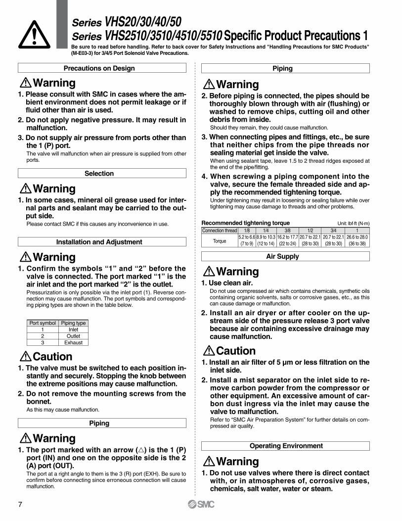
Precautions on Design
Warning1. Please consult with SMC in cases where the am-
bient environment does not permit leakage or if fluid other than air is used.
2. Do not apply negative pressure. It may result in malfunction.
3. Do not supply air pressure from ports other than the 1 (P) port. The valve will malfunction when air pressure is supplied from other ports.
Piping
Warning1. The port marked with an arrow ( ) is the 1 (P)
port (IN) and one on the opposite side is the 2 (A) port (OUT). The port at a right angle to them is the 3 (R) port (EXH). Be sure to confirm before connecting since erroneous connection will cause malfunction.
Piping
Warning2. Before piping is connected, the pipes should be
thoroughly blown through with air (flushing) or washed to remove chips, cutting oil and other debris from inside.Should they remain, they could cause malfunction.
3. When connecting pipes and fittings, etc., be sure that neither chips from the pipe threads nor sealing material get inside the valve.When using sealant tape, leave 1.5 to 2 thread ridges exposed at the end of the pipe/fitting.
4. When screwing a piping component into the valve, secure the female threaded side and ap-ply the recommended tightening torque.Under tightening may result in loosening or sealing failure while over tightening may cause damage to threads and other problems.
Selection
Warning1. In some cases, mineral oil grease used for inter-
nal parts and sealant may be carried to the out-put side.Please contact SMC if this causes any inconvenience in use.
Operating Environment
Warning1. Do not use valves where there is direct contact
with, or in atmospheres of, corrosive gases, chemicals, salt water, water or steam.
Air Supply
Warning1. Use clean air.
Do not use compressed air which contains chemicals, synthetic oils containing organic solvents, salts or corrosive gases, etc., as this can cause damage or malfunction.
2. Install an air dryer or after cooler on the up-stream side of the pressure release 3 port valve because air containing excessive drainage may cause malfunction.
Caution1. Install an air filter of 5 µm or less filtration on the
inlet side.2. Install a mist separator on the inlet side to re-
move carbon powder from the compressor or other equipment. An excessive amount of car-bon dust ingress via the inlet may cause the valve to malfunction.Refer to “SMC Air Preparation System” for further details on com-pressed air quality.
Installation and Adjustment
Warning1. Confirm the symbols “1” and “2” before the
valve is connected. The port marked “1” is the air inlet and the port marked “2” is the outlet.Pressurization is only possible via the inlet port (1). Reverse con-nection may cause malfunction. The port symbols and correspond-ing piping types are shown in the table below.
Caution1. The valve must be switched to each position in-
stantly and securely. Stopping the knob between the extreme positions may cause malfunction.
2. Do not remove the mounting screws from the bonnet.As this may cause malfunction.
Piping typeInlet
OutletExhaust
Port symbol123
3/420.7 to 22.1(28 to 30)
Connection thread
Torque
Recommended tightening torque Unit: lbf·ft (N·m)
1/85.2 to 6.6(7 to 9)
1/48.9 to 10.3(12 to 14)
3/816.2 to 17.7(22 to 24)
1/220.7 to 22.1(28 to 30)
126.6 to 28.0(36 to 38)
7
Series VHS20/30/40/50Series VHS2510/3510/4510/5510 Specific Product Precautions 1Be sure to read before handling. Refer to back cover for Safety Instructions and "Handling Precautions for SMC Products" (M-E03-3) for 3/4/5 Port Solenoid Valve Precautions.
Built-in Silencer (Option)Bronze Sintered Metal Element
CautionProducts made of bronze may contain uneven color due to the oxidization process of the atmosphere.However, this oxidization process occurs in the limited range of less than 1µm of thickness and is so thin as to not affect the product characteristics.The uneven color occurs depending on the storage duration before utilization (stock as a product, stock in customer)
If this is a problem, please contact SMC so that SMC can pre-treat them with nickel plating.
Operating Environment
Warning2. Do not use in an explosive atmosphere.?3. Do not use in locations subject to vibration or im-
pact. Confirm the specifications for each series.4. A protective cover should be used to shield
valves from direct sunlight.5. Shield valves from radiated heat generated by
nearby heat sources.6. Employ suitable protective measures in loca-
tions where there is contact with water droplets, oil, or welding spatter.
7. Install a silencer into port 3 (R) to prevent the in-gress of dust if there is a lot of dust in the atmo-sphere.If dust enters the valve via port 3 (R) , it may cause air leakage.
Maintenance
Warning1. Perform maintenance procedures as shown in
the instruction manual.If handled improperly, malfunction or damage of machinery or equipment may occur.
2. Do not disassemble the product.Improper handling will cause malfunction or breakage of the ma-chinery or equipment.
3. When equipment is to be removed, first confirm that measures are in place to prevent dropping of driven objects and run-away of equipment, etc. Then cut the supply air pressure and electric power, and exhaust all compressed air from the system using its residual pressure release func-tion.When the equipment is to be started again after remounting or re-placement, first confirm that measures are in place to prevent lurch-ing of actuators and then confirm that equipment operates normally.
Caution1. Once a lubricant is introduced, be sure to
continue lubrication.If it is discontinued, malfunction may result due to loss of the initial lubricant. Apply class 1 turbine oil (ISO VG32) as a lubricant. Use of other lubricants may cause malfunction.
Be sure to read before handling. Refer to back cover for Safety Instructions and "Handling Precautions for SMC Products" (M-E03-3) for 3/4/5 Port Solenoid Valve Precautions.
8
Series VHS20/30/40/50Series VHS2510/3510/4510/5510 Specific Product Precautions 2
1. The compatibility of the product is the responsibility of the person who designs the equipment or decides its specifications.Since the product specified here is used under various operating conditions, its compatibility with specific equipment must be decided by the person who designs the equipment or decides its specifications based on necessary analysis and test results. The expected performance and safety assurance of the equipment will be the responsibility of the person who has determined its compatibility with the product. This person should also continuously review all specifications of the product referring to its latest catalog information, with a view to giving due consideration to any possibility of equipment failure when configuring the equipment.
2. Only personnel with appropriate training should operate machinery and equipment.The product specified here may become unsafe if handled incorrectly. The assembly, operation and maintenance of machines or equipment including our products must be performed by an operator who is appropriately trained and experienced.
3. Do not service or attempt to remove product and machinery/equipment until safety is confirmed.1. The inspection and maintenance of machinery/equipment should only be performed
after measures to prevent falling or runaway of the driven objects have been confirmed.
2. When the product is to be removed, confirm that the safety measures as mentioned above are implemented and the power from any appropriate source is cut, and read and understand the specific product precautions of all relevant products carefully.
3. Before machinery/equipment is restarted, take measures to prevent unexpected operation and malfunction.
4. Contact SMC beforehand and take special consideration of safety measures if the product is to be used in any of the following conditions. 1. Conditions and environments outside of the given specifications, or use outdoors or
in a place exposed to direct sunlight.2. Installation on equipment in conjunction with atomic energy, railways, air navigation,
space, shipping, vehicles, military, medical treatment, combustion and recreation, or equipment in contact with food and beverages, emergency stop circuits, clutch and brake circuits in press applications, safety equipment or other applications unsuitable for the standard specifications described in the product catalog.
3. An application which could have negative effects on people, property, or animals requiring special safety analysis.
4. Use in an interlock circuit, which requires the provision of double interlock for possible failure by using a mechanical protective function, and periodical checks to confirm proper operation.
Warning
Limited warranty and Disclaimer/Compliance Requirements The product used is subject to the following “Limited warranty and Disclaimer” and “Compliance Requirements”.Read and accept them before using the product.
1. The product is provided for use in manufacturing industries.The product herein described is basically provided for peaceful use in manufacturing industries. If considering using the product in other industries, consult SMC beforehand and exchange specifications or a contract if necessary. If anything is unclear, contact your nearest sales branch.
Caution
Limited warranty and Disclaimer1. The warranty period of the product is 1 year in service or 1.5 years after the
product is delivered, whichever is first. 2)
Also, the product may have specified durability, running distance or replacement parts. Please consult your nearest sales branch.
2. For any failure or damage reported within the warranty period which is clearly our responsibility, a replacement product or necessary parts will be provided. This limited warranty applies only to our product independently, and not to any other damage incurred due to the failure of the product.
3. Prior to using SMC products, please read and understand the warranty terms and disclaimers noted in the specified catalog for the particular products.
2) Vacuum pads are excluded from this 1 year warranty.A vacuum pad is a consumable part, so it is warranted for a year after it is delivered. Also, even within the warranty period, the wear of a product due to the use of the vacuum pad or failure due to the deterioration of rubber material are not covered by the limited warranty.
Compliance Requirements1. The use of SMC products with production equipment for the manufacture of
weapons of mass destruction (WMD) or any other weapon is strictly prohibited.
2. The exports of SMC products or technology from one country to another are governed by the relevant security laws and regulations of the countries involved in the transaction. Prior to the shipment of a SMC product to another country, assure that all local rules governing that export are known and followed.
These safety instructions are intended to prevent hazardous situations and/or equipment damage. These instructions indicate the level of potential hazard with the labels of “Caution,” “Warning” or “Danger.” They are all important notes for safety and must be followed in addition to International Standards (ISO/IEC) 1), and other safety regulations.
1) ISO 4414: Pneumatic fluid power – General rules relating to systems. ISO 4413: Hydraulic fluid power – General rules relating to systems. IEC 60204-1: Safety of machinery – Electrical equipment of machines. (Part 1: General requirements) ISO 10218-1: Manipulating industrial robots – Safety. etc.
Caution indicates a hazard with a low level of risk which, if not avoided, could result in minor or moderate injury.
Warning indicates a hazard with a medium level of risk which, if not avoided, could result in death or serious injury.
Caution:
Warning:
Danger : Danger indicates a hazard with a high level of risk which, if not avoided, will result in death or serious injury.
Safety Instructions
Safety Instructions Be sure to read “Handling Precautions for SMC Products” (M-E03-3) before using.
SMC Corporation of America10100 SMC Blvd., Noblesville, IN 46060 www.smcusa.comSMC Pneumatics (Canada) Ltd.www.smcpneumatics.ca
(800) SMC.SMC1 (762-7621)e-mail: [email protected] International inquiries: www.smcworld.com
© 2012 SMC Corporation of America, All Rights Reserved.
All reasonable efforts to ensure the accuracy of the information detailed in this catalog were made at the time of publishing. However, SMC can in no way warrant the information herein contained as specifications are subject to change without notice.RO-5M-RRD