modern corrugated horn antennas - semantic scholarprácticamente fin a una etapa que me ha venido...
TRANSCRIPT

MMooddeerrnn CCoorrrruuggaatteedd HHoorrnn AAnntteennnnaass
Memoria de la tesis Doctoral realizada por: Jorge Teniente Vallinas
Y dirigida por: Dr. Carlos del Río Bocio
Para optar al grado de: Doctor Ingeniero en Telecomunicación
Grupo de Antenas
Departamento de Ingeniería Eléctrica y Electrónica Universidad Pública de Navarra
Pamplona, Julio de 2003


A Marian, por haberme alegrado
la vida y haberme aguantado
en los momentos difíciles


V Premios Rosina Ribalta Convocatoria 2002 – 2003 A los mejores proyectos de tesis doctoral en el ámbito de las Tecnologías de la Información y de las Comunicaciones
Este trabajo ha sido galardonado con el segundo premio de la
V edición de los premios Rosina Ribalta de la Fundación
EPSON IBÉRICA al segundo mejor proyecto de tesis doctoral
en el ámbito de las Tecnologías de la Información y de las
Comunicaciones. Año 2002-2003
This work won the second prize of the V edition of the Rosina
Ribalta award given by the EPSON IBÉRICA Foundation to
the second best Ph. D thesis project about Information an
Communications Technology. Year 2002-2003

vii
Agradecimientos
Por fin ha llegado la hora de escribir estas ansiadas líneas que a
continuación se suceden. Escribir los agradecimientos es probablemente una
de las partes más difíciles en la realización de una tesis doctoral, por un lado
porque son normalmente muy personales y por otro lado porque además
siempre se sabe que serán las líneas primeramente leídas cuando entregue
esta tesis doctoral a mis compañeros y gente allegada porque en el fondo
todos somos un poco chismosos.
Para mi encontrarme escribiendo los agradecimientos supone poner
prácticamente fin a una etapa que me ha venido preocupando durante los
últimos meses ya que son las últimas líneas que escribo de esta tesis antes
de depositarla en el registro, ello me llena de alegría ya que ahora volveré a
tener tiempo para estar con mi novia e ir a pescar a mosca, ya que las tengo
un poco olvidadas a las dos.
Durante estos seis años de realización de la tesis en primer lugar
quiero agradecer y muy especialmente a mi director de tesis, el Dr. Carlos
del Río con el que he compartido principalmente los devenires de la tesis,
con quien he acudido a multitud de congresos y quien siempre ha dado la
cara por mí y ha procurado defender mis intereses. Además no me puedo
olvidar de mencionar también especialmente al Dr. Ramón Gonzalo, el cual
fue mi director de proyecto fin de carrera en el año 1997 y que ahora
durante la tesis se ha convertido además de un asesor, en un compañero que
sabe ponerme las pilas cuando es necesario.
Durante estos seis años he realizado dos estancias en el extranjero, la
primera en Holanda que resulto ser inolvidable por la cantidad de gente
estupenda que conocí y por que a pesar de que no podía practicar mi afición
favorita (la pesca a mosca) me dio lástima a volver. En ese transcurso de
viii
tiempo no me puedo olvidar especialmente de mi tutor allí, el Dr. Javier
Martí el cual me enseñó muchas cosas sobre la medida de antenas y me dejo
libertad a la hora de controlar el CATR del que el era responsable. También
guardo un especial recuerdo del Dr. Peter de Maagt y su nutrido grupo
internacional con el que me reunía todos los días a la hora de comer y en
donde aprendí a soltarme hablando inglés de una vez por todas, gracias
Peter. En cuanto a mis compañeros de fiestas y juergas en Holanda, merecen
mención especial; Eduardo, David Lemus, Santiago Vázquez, Ramón
Torres, Iñigo Sarriés, Daniel, Iñigo Ederra, Elvira, Pablo, Santiago Soley y
otros muchos mas de los que ya ni me acuerdo de su nombre, perdonad mi
omisión los no mencionados si algún día leéis esto y no os sentís
identificados.
A mi vuelta a España retomando de nuevo la tesis doctoral en antenas
corrugadas después de mi periplo holandés en el campo de la medida de
antenas merece la pena recordar especialmente a Gemma y Cristina con
quienes tan buenos ratos de asueto pase y para las cuales siempre había una
sonrisa en la boca que compartir con los demás; sin olvidar claro está al
resto de compañeros del laboratorio, los que pasaron y los que ahora están.
Además merecen mención muy especial por llevarlos muy dentro, la
gente de la Asociación Navarra de Pescadores a Mosca y del comité local de
AEMS-Ríos con vida de Navarra por ayudarme a reencontrarme con mi
afición favorita y compartir con ellos tantas y tantas jornadas de pesca, de
tertulias sobre pesca y de conservación ríos y gestión de pesca.
También quiero de recordar aquí como no a mis amigos de Lodosa que
tan fenomenalmente me acogieron de vuelta a mi querida tierra. Y con
quienes he compartido una fuerte amistad arraigada desde la infancia y
como no a mi familia que siempre me ha apoyado a seguir adelante con los
estudios.

ix
En mi recta final de la tesis doctoral recuerdo especialmente a mi
hermana Leyre con la que he compartido casi dos años de casa hasta que
recientemente se ha casado con su novio de toda la vida Oscar. Enhorabuena
tata.
No se me debe olvidar una mención especial a mi compañero de
despacho de siempre, Iñigo Ederra que fue además compañero en mis
estancias en Holanda e Inglaterra, el cual nunca se ha quejado de mis
tonterías y que sabe aguantarme estoicamente.
En el verano del 2002 realicé una nueva estancia en el extranjero
concretamente en Inglaterra seleccionado para trabajar en el proyecto
StarTiger y merece la pena que mencione en primer lugar al jefe del
proyecto, el Dr. Chris Mann que siempre sabe transmitir entusiasmo a pesar
de que las cosas ya pinten muy negras y es capaz de hacer trabajar a todo el
grupo hasta altas horas de la madrugada siempre que aún quede un mínimo
resquicio de éxito, va por ti Chris. También debo mencionar al resto de mis
compañeros de proyecto y especialmente a James, Frank, Dario e Iñigo otra
vez más.
He de agradecer con estas líneas también a Noelia el haberme prestado
un diseño suyo de una antena choke-gaussiana para ilustrar esta tesis y por
haber continuado la investigación de antenas corrugadas de perfil gaussiano
donde yo la deje aparcada para disponer de tiempo para la escritura.
Terminando ya, quiero agradecer especialmente a la Fundación Epson-
Ibérica por haberme otorgado por este proyecto el segundo premio de la V
edición de premios Rosina Ribalta a los mejores proyectos de tesis doctoral
en el ámbito de las tecnologías de la información y de las comunicaciones,
llego para mí como agua de Mayo en Junio.
Y por ultimo no me podía olvidar como no de la persona más especial,
la cual conocí a primeros de Mayo de 2002 y que actualmente es mi novia;

x
este agradecimiento especial va para Marian, la chiquita que me alegró la
vida, que supo aguantar firme mis cuatro meses de separación cuando
apenas habíamos empezado a conocernos y que ha sabido aguantar mis
cambios de carácter cuando las premuras de tiempo obligaban a trabajar
demasiado en pos de terminar este manuscrito. Así pues que estas líneas le
demuestren lo que yo la quiero.

xi
Resumen
La presente tesis doctoral ha tenido como propósito sentar las bases de
diseño de las antenas corrugadas de última generación que se vienen
desarrollando desde 1995 en el seno del Grupo de Antenas de la
Universidad Pública de Navarra.
Este tipo de antenas, ahora mundialmente conocidas como antenas
corrugadas Gaussianas o más recientemente con el término “corrugated
GPHA’s” donde el término GPHA hace referencia a las siglas en inglés
“Gaussian Profiled Horn Antennas” que significa Antenas de Bocina de
Perfil Gaussiano; son en la actualidad la mejor solución posible para
conseguir patrones de radiación de muy altas prestaciones.
Concretamente, las antenas corrugadas de perfil gaussiano superan al
resto de antenas de bocina corrugadas en dos aspectos:
- Es posible diseñar antenas con lóbulos laterales muchísimo más bajos
que con cualquier otro tipo de perfil corrugado.
- Son, en general, más cortas que el resto de antenas corrugadas debido
a que sus prestaciones son mejores.
Por todo ello, actualmente son la opción elegida por multitud de
grupos de investigación a nivel mundial para realizar las antenas de bocina
corrugadas que requieren sus proyectos.
Antenas de este tipo ya han sido embarcadas en satélites como
Hispasat 1C e Hispasat 1D, van a ser utilizadas para el instrumento
aerotransportado de la ESA llamado Marschals, serán utilizadas en el futuro
satélite Planck de la ESA y actualmente una nueva versión muy
prometedora esta siendo comercializada por la empresa inglesa Flann
Microwave, Ltd.

xii

xiii
Abstract
This Ph. D. manuscript has the main purpose of summarizing the
design techniques of the new technology corrugated horn antennas
developed since 1995 in the Antenna Group of the Public University of
Navarra.
This type of world-wide accepted antennas, known as corrugated
Gaussian Profiled Horn Antennas, (GPHA’s); are now-a-days the best
possible solution to obtain radiation patterns of very high restrictive
requirements.
Corrugated GPHA’s are better than the rest of corrugated horn
antennas in two particular aspects:
- They present much lower sidelobes than any other corrugated profile
- They are usually shorter than the rest of corrugated profiles because
their performance qualities are superior.
Therefore, this antennas are usually the preferred choice of many
research groups around the world to develop corrugated horns for their
research projects.
Antennas of this type are at present on board of Hispasat 1C and
Hispasat 1D satellites, are going to be used in the ESA funded Marschals
airborne system, will be used in a near future in the ESA’s Planck satellite
and now-a-days a new version of a corrugated GPHA is being
commercialised by the British company Flann Microwave, Ltd.

xiv

xv
Table of Contents
Mención premio Rosina Ribalta v
Agradecimientos vii
Resumen xi
Abstract xiii
Table of Contents xv
Chapter 1. Introduction 1 1.1 Background 1
1.2 Organisation of chapters 4
Chapter 2. Corrugated horn antenna theory 7 2.1 Principles of operation of corrugated horns 7
2.2 Hybrid modes 11 2.2.1 Simple mathematical definition of hybrid modes 11 2.2.2 The fundamental mode of a corrugated waveguide, HE11 mode 14 2.2.3 Radiation properties of the HE11 mode of a corrugated
waveguide 15
2.3 Paraxial free space modes (Gaussian modes) and their relation to waveguide modes. 19
2.4 References 21
Chapter 3. Conical corrugated horn antennas 23 3.1 Conical corrugated horn antenna design 25 3.1.1 Corrugation parameters design 29
3.2 Design of a 22 dB conical corrugated horn antenna 32
3.3 References 35

xvi
Chapter 4. Corrugated Gaussian Profiled Horn Antenna design 37
4.1 Corrugated Gaussian Profiled Horn Antenna definition 38
4.2 Gaussian profiled corrugated horn antenna design 41
4.3 Gaussian profiled corrugated horn antenna performance 49
4.4 Design of a 22 dB corrugated Gaussian Profiled Horn Antenna
50
4.5 Conclusions 52
4.6 References 52
Chapter 5. Corrugated TE11 to HE11 mode converter design 55 5.1 Design of a TE11 to HE11 mode converter using gaussian
techniques 56
5.1.1 Gaussian TE11 to HE11 mode converter performance 58 5.1.2 Corrugated GPHA versus corrugated conical TE11 to HE11
mode converters 59
5.2 Design of a symmetric GPHA TE11 to HE11 mode converter 61 5.2.1 Symmetrical corrugated GPHA TE11 to HE11 mode converter
performance 63
5.3 Designing a Corrugated TE11 to HE11 mode converter 65
5.4 Corrugated TE11 to HE11 mode converter bandwidth comparison
69
5.5 Other types of corrugated TE11 to HE11 mode converters 71 5.5.1 Example of a shorter TE11 to HE11 mode converter 71 5.5.2 Choked TE11 to HE11 mode converter 73
5.6 Conclusions 75
5.7 References 76
Chapter 6. Complete antenna design using corrugated Gaussian Profiled Horn Antennas 79
6.1 Complete design of a corrugated GPHA with a conical corrugated input as TE11 to HE11 mode converter 80

xvii
6.1.1 Design of a 22 dB combination conical+GPHA 85
6.2 Complete design of a corrugated GPHA with a corrugated GPHA input as TE11 to HE11 mode converter 88
6.3 Complete design of a corrugated GPHA with a symmetrical corrugated GPHA input as TE11 to HE11 mode converter 89
6.3.1 Design of a 22 dB combination symmetrical GPHA + GPHA 93
6.4 Comparison between different combinations 95
6.5 Other possibilities to excite a corrugated GPHA 99 6.5.1 Design of a 22 dB combination CSIRO + GPHA 99 6.5.2 Design of a 22 dB combination Choked + GPHA 101
6.6 On the bandwidth of the different complete GPHA profiles 103
6.7 On the corrugation depth 107
6.8 Design tricks and rules 109 6.8.1 Reducing the size of the complete corrugated GPHA 110 6.8.2 Reducing the crosspolar level and the return loss of any
corrugated horn antenna 110
6.9 References 113
Chapter 7. Applications of corrugated GPHA 115 7.1 Corrugated GPHA design for low power testing of the quasioptical
transmission lines at TJ-II stellerator 117
7.2 Corrugated GPHA design for Hispasat 1C satellite 121
7.3 Corrugated GPHA feedhorns for ESA funded MARSCHALS airborne system 127
7.4 Ultra wide band corrugated GPHA design for the far field range measurement chamber at UPNA 133
7.5 Choked corrugated GPHA. Extremely compact low sidelobe antenna design 137
7.6 References 144

xviii
Chapter 8. Conclusions an guidelines for future research 147 8.1 Conclusions 147
8.2 Guidelines for future research 149
Appendix I. Characteristics of the Fundamental Gaussian mode 151
A1.1 General equations of the gaussian modes 152
A1.2 Fundamental gaussian beam mode 154 A1.2.1 Propagation of the fundamental gaussian mode 154 A1.2.2 Field intensity and carried power of a fundamental gaussian
beam mode 157
A1.2.3 Phase fronts of a fundamental gaussian beam mode 160
A1.3 References 163
Appendix II. Resonance spikes in corrugated horn antennas 165 A2.1 Origin of the resonance spikes 165
A2.2 How to eliminate the resonance spikes 167
A2.3 References 170
Appendix III. Relation between Beamwidth and Directivity 171
List of Publications 173
Epilogue 179

Chapter 1
Introduction
In this introductory chapter, a perspective of the state of the art
evolution for corrugated horn antenna technology is presented. In addition,
an outline of the structure of this thesis is given.
1.1 Background
There are three main reasons for the existence of corrugated horn
antennas. Firstly, they exhibit radiation pattern symmetry, which offers the
potential for producing reflector antennas with high gain and low spillover;
secondly, they radiate with very low crosspolarisation, which is essential in
dual polarisation systems and finally, they offer a wide bandwidth response.
Now-a-days, in the age of the communications, horn antennas take a
very important role in the development of the actual and future
communications systems with high requirements in their radiations patterns.
In fact, corrugated feeds are the best feeds ever developed.
Ten to twenty years ago, corrugated horn antennas were restricted to
be used in high performance applications, like being on board of satellites,
earth station radiotelescope horns, antenna measurement chambers and very
few more applications. They were restricted to those applications for two
main reasons: difficulties in the design and difficulties in the manufacture
process of a corrugated feed.
At present, the communication systems require really high
performance antennas; sidelobe and crosspolar levels should be reduced in

Modern Corrugated Horn Antennas 2
the radiation pattern as well as the size of the antenna. Low crosspolar levels
are inherent to the corrugated horn antenna technology and this parameter
has been conveniently improved during the last decades with the use of
corrugated feeds. But sidelobe level of corrugated horns has got stuck and
no improvements have been made till the last five years. Probably, the
improvement in sidelobe level has not been really necessary up to now. The
incredible quantity of new communication systems that interact between
them has made necessary to reduce the mutual interferences through
sidelobes. In fact, the major benefits from the extremely low sidelobe
interference characteristics are to reduce both operational costs and also the
susceptibility to jamming or eavesdropping in military and secure
applications.
The manufacture process for corrugated feeds has been improved
during the last years due to the massive use of numerical milling machines
and the improvement made in computer technology to control those
machines. Additionally, sometimes to implement mm-wave and
submm-wave corrugated horns, expensive electroforming techniques are
needed, specially where thin corrugations, small size and precision are
required. Electroforming techniques have the disadvantage of the necessity
to manufacture a mandrel for each antenna that will be destroyed afterwards
becoming a very expensive manufacture method.
Regarding to the global dimensions of corrugated horns, we can
observe that its radiation aperture is almost determined for a given
directivity; although a horn antenna can be shortened in its length. Shorter
antenna profiles are really the preferred ones for practically all applications,
satellites launching reduction of weight, lighter posts for base station

Introduction 3
antennas, and additionally they should be as well easier and cheaper to
manufacture.
Now-a-days, likely global market applications for corrugated feeds
are: compact parabola feeds, covert surveillance, secure communications,
base station power saving, reduced interference... So corrugated feeds will
no more be restricted nearly exclusively to expensive satellite market.
A huge research has been made in the last years by several groups
around the world in optimising corrugated horn antenna profiles, using
advanced optimisation programs with the aid of the increasing speed of
computers. Each group has its own profiles and reaches its own conclusions,
but mainly, the profiles chosen for the most high performance applications
are the ones suggested and developed by the Antenna Group of the Public
University of Navarra a few years ago. The corrugated Gaussian Profiled
Horn Antennas (GPHA’s) are at the moment at the highest level of
performance among any other corrugated horn antenna.
In this manuscript a modern method to design high performance
GPHA’s is explained and really good results are being obtained from it.
Achievements as making an antenna for HISPASAT 1C and HISPASAT 1D
satellites or entering the market with a company as Flann Microwave Ltd. in
the last few months with a brand new antenna (http://www.flann.com) could
be considered as an absolute success. Other studies have been performed for
high requirements applications; the MARSCHALS and the PLANCK
instruments and many others applied by other research groups (CSIRO,
Queen Mary College, Jet Propulsion Laboratory...) used the technology
proposed in the nineties by the Antenna Group of the Public University of
Navarra. We hope this research will be expanded a lot more in a near future
with the brand new profile types presented at the end of this manuscript.

Modern Corrugated Horn Antennas 4
1.2 Organisation of chapters
This chapter has introduced the reader to the work performed during
this doctorate Thesis, providing some historical background to corrugated
horn antenna technology and outlining the motivation for the research
presented. The mayor novelties of the work performed have been also
explained.
Chapter 2 presents the principles of corrugated horn antenna theory.
An overview of how corrugations affect the electromagnetic field linked to a
modal theory inside a corrugated waveguide is presented. Additionally,
some aspects of the paraxial free space radiation by means of gaussian
modes is covered.
The classical conical corrugated horn antenna design method is
recollected completely in chapter 3. An example of a conical corrugated
horn antenna design is developed to evaluate its characteristics and compare
it with other designs to be studied in the subsequent chapters.
Once the classical conical corrugated horn antennas have been
covered, in chapter 4 the new profiles proposed by the Antenna Group of the
Public University of Navarra are explained. This chapter covers the
Gaussian Profiled Horn Antenna (GPHA) definition, performance and
design. A corrugated GPHA design is developed as well for comparison
with the previous chapter conical corrugated horn antenna design.
The objective of chapter 5 is to implement the specific device (TE11 to
HE11 mode converter) to feed correctly the corrugated GPHA developed in
the previous chapter. Three different ways to perform this device are
explained carefully. Another possibilities under research are briefly
explained.

Introduction 5
In chapter 6, the information presented in chapters 4 and 5 is joined to
implement the complete design using corrugated GPHA’s. The design
method will combine the three different ways to implement the input device
of a corrugated GPHA. An example of a 22 dB directivity horn antenna
design is also developed to make comparisons in electromagnetic behaviour
and size. Besides, other new possibilities to feed a corrugated GPHA are
briefly covered (under research at present). At the end of chapter 6, a
bandwidth comparison, the design characteristics of the corrugation
parameters and some tricks and rules that will help the designer are also
presented.
Several applications developed during the six year research of this
thesis are presented in chapter 7. In those applications the reader can check
the way this research has been performed discovering the most important
aspects of this type of corrugated horn.
Chapter 8 presents the main conclusions of this thesis and the
guidelines for a future and promising research.

Modern Corrugated Horn Antennas 6

Chapter 2
Corrugated horn antenna theory
Corrugated horns have become now-a-days the preferred choice of
feed antenna for use in high restrictive applications. This is because of their
superior radiation performance and in particular their high copolar pattern
symmetry and low crosspolarisation.
This chapter starts with the principles of the electrical behaviour of the
electrical fields inside a corrugated waveguide. The hybrid mode basis as a
tool to help in the analysis of corrugated horns and the relation between
waveguide modes and free space gaussian modes are explained to
understand the behaviour of the different types of corrugated horn antennas
that are going to be covered in this thesis.
Figure 2.1. Corrugated waveguide
2.1 Principles of operation of corrugated horns The operation principle of corrugated horns can be physically
explained by considering the way in which the corrugated wall affects the
field distribution inside a corrugated waveguide (fig. 2.1). As it will be
demonstrated, the corrugations change the fields travelling through the

Modern Corrugated Horn Antennas 8
waveguide to produce the desirable radiating properties of axial beam
symmetry, low sidelobes and low crosspolarization [1].
A linear electric field for low crosspolar level will be desirable but it
cannot be obtained with smooth waveguides that only support pure
transverse electric (TE) or a pure transverse-magnetic (TM) modes. These
modes have the aperture electric field lines curved (fig. 2.2). Therefore a
multimode horn should be designed. In [2], a special horn design to obtain
an appropriate mode mixture by the addition of TE11 and TM11 modes in a
particular proportion and phase is presented, but its bandwidth is very
narrow.
Figure 2.2. TE11 and TM11 aperture electric fields
Theoretically, as it will be shown later, the hybrid modes HE1n present
at the aperture of a circular waveguide perfectly linear electric field lines.
The dominant hybrid mode in corrugated waveguide (HE11) has the
following aperture electric fields, [1,3,4,5]:

Corrugated horn antenna theory 9
1 0 2 2
2 2
2.405 ( ) 2.405( ) ( ) cos(2 )
( ) 2.405( ) sin(2 )
x
y
X YE A J r A J r
R k R RX Y
E A J rk R R
φ
φ
−= ⋅ ⋅ − ⋅ ⋅ ⋅ ⋅ ⋅
⋅−
= ⋅ ⋅ ⋅ ⋅ ⋅⋅
where ( )0J k r⋅ y ( )2J k r⋅ are Bessel functions of the first kind, k is the free
space wavenumber, A1 and A2 are the amplitude coefficients and X and Y are
the impedance and admittance at the boundary r R= given by
0
0
1
1
z
z
EX j H Z
HY j E Z
φ
φ
= − ⋅ ⋅ = ⋅ ⋅
where Z0 is the impedance of free space.
Figure 2.3. HE11 aperture electric field of a circular corrugated horn
From equation 2.1 it is seen that, if the term ( )X Y− vanishes, the
aperture field is independent of the angular variable φ and yE 0= , so no
crosspolarized field exists.
The condition of zero crosspolarized field ( ) 0X Y− = can be obtained
if X and Y are equal values or if X and Y are both equal to zero. This second
(2.1)
(2.2)

Modern Corrugated Horn Antennas 10
case is called balanced hybrid condition. If there are enough corrugations
per wavelength, the azimuthal electric field ( Eφ ) will be equal to zero in
r R= and then 0X = . On the other hand, if the corrugation ridge (w) is
narrow and quarter wavelength deep ( 4d λ= ), they will act as short
transmission lines where the short circuit at the end is transferred to an open
circuit at the corrugation boundary r R= . This ensures that there will not be
axial currents generated by Hφ , so this too will be zero and then 0Y = .
The above description is only a simple physical explanation as to why
the corrugated walls produce an approximately linearly polarized aperture
field, see figure 2.3.
Because of the fact that the corrugation depth is frequency dependant,
the balanced hybrid only happens at a single frequency and zero
crosspolarization will be dominated by this aspect. At other frequencies
apart from 0f there will be a crosspolarized component. However, equation
2.1 shows that the crosspolar term decreases as k R⋅ increases, so the larger
the diameter of the horn, the wider will be the bandwidth for a given
crosspolar level.
The above explanation has described the behaviour for an open-ended
waveguide, but almost all horns have a finite flare angle. Then the radiation
patterns are partly controlled by the additional factor of the antenna profile.
This factor is a function of two parameters: the diameter of the horn and the
flare angle; so that factor will increase for a short horn with a wide flare
angle and a long horn with a narrow flare angle. As this factor increases, the
radiation pattern becomes more and more determined by this opening factor
value and less and less by the aperture fields. In the development of this
thesis, only tightly controlled aperture angle of the horn antennas is going to

Corrugated horn antenna theory 11
be considered. Then, the radiation of the horn designs will be completely
controlled by the aperture fields.
2.2 Hybrid modes To define properly the field inside a circular waveguide the most
known basis used is the TE and TM family of modes which are direct
solution of the wave equation inside a smooth circular waveguide [6]. But if
the waveguide is corrugated it could be also useful to define the field inside
the waveguide by the family of hybrid modes HE and EH. So in fact we can
choose to define the field inside the corrugated horn antennas in terms of TE
and TM modes or in terms of HE and EH modes.
Along this manuscript we will use both families to define the fields,
and we will use in each particular case the family which better explains the
behaviour we want to remark.
2.2.1 Simple mathematical definition of hybrid modes
Transverse electric and magnetic modes (TE and TM) are usually well
known in waveguide theory. On the other hand, hybrid modes (those modes
which doesn’t present pure transverse components along the waveguide) are
not so well known. It is interesting to aid in the knowledge of corrugated
horn antennas to deepen in the understanding of hybrid modes of a
corrugated waveguide. So in this section, a brief physical explanation of the
properties of hybrid modes is going to be developed.
If we assume balanced hybrid condition, hybrid modes can be defined
with the following simplified equations:

Modern Corrugated Horn Antennas 12
HEmn modes
( ) ( )
( ) ( )
,1
0
1 ,
,1
0
1 ,
'
'
( )2, cos 1
( )
( )2, sin 1
( )
m nm
xm m n
m nm
ym m n
rJZ RE r m
JR
rJZ RE r m
JR
χ
χ
χ
χ
φ φπ
φ φπ
−
−
−
−
⋅⋅
= ⋅ ⋅ − ⋅ ⋅
⋅⋅
= ⋅ ⋅ − ⋅ ⋅
EHmn modes
( ) ( )
( ) ( )
,1
0
1 ,
,1
0
1 ,
'
'
( )2, cos 1
( )
( )2, sin 1
( )
m nm
xm m n
m nm
ym m n
rJZ RE r m
JR
rJZ RE r m
JR
χ
χ
χ
χ
φ φπ
φ φπ
+
−
+
−
⋅⋅
= ⋅ ⋅ + ⋅ ⋅
⋅⋅
= ⋅ ⋅ + ⋅ ⋅
where ,m nχ are the roots of the Bessel functions ( ( )1 0mJ x− = for HE modes
and ( )1 0mJ x+ = for EH modes), R is the waveguide radius, m and n the
radial and azimuthal indexes of the modes and 0Z is the impedance of free
space.
Figure 2.4. HEmn and EHmn aperture electric fields (linear scale)
(2.5)
(2.4)
Corrugated horn antenna theory 13
From equations 2.4 and 2.5, the main property we can extract is for
1m = , the HE1n modes are linearly polarized, ( 0yE = see equation 2.4),
however the EH1n modes have a high crosspolar component, ( 0yE ≠ see
equation 2.5).
The aperture electric field of the first HEmn and EHmn modes is
represented in fig. 2.4, the crosspolar component of EH1n can be checked.
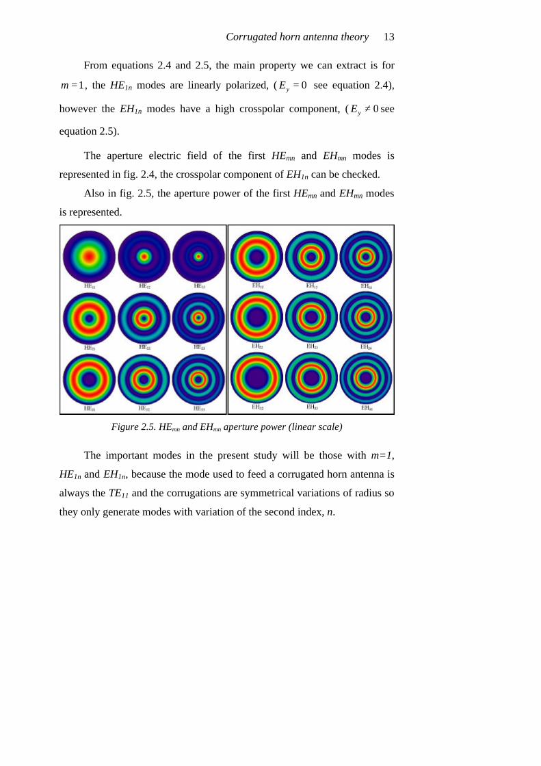
Also in fig. 2.5, the aperture power of the first HEmn and EHmn modes
is represented.
Figure 2.5. HEmn and EHmn aperture power (linear scale)
The important modes in the present study will be those with m=1,
HE1n and EH1n, because the mode used to feed a corrugated horn antenna is
always the TE11 and the corrugations are symmetrical variations of radius so
they only generate modes with variation of the second index, n.
Modern Corrugated Horn Antennas 14
2.2.2 The fundamental mode of a corrugated waveguide, HE11 mode
The HE11 mode is the fundamental mode of a corrugated waveguide
and presents linear electric field at the aperture, (fig. 2.2). From equation
2.4, this mode is defined only by a unique axial component, (equation 2.6).
( )
( )
1,10
0
0 1,1'
( )2,
( )
, 0
x
y
rJZ RE r
JR
E r
χ
χφ
πφ
⋅⋅
= ⋅⋅
=
where 1,1χ is the root of the Bessel function ( )0 0J x = and in this particular
case, for the HE11 mode is 1,1 2.404826χ = . Equation 2.6 can be obtained
from a particularization of equation 2.4 or from equation 2.1 assuming
X-Y=0 (balanced hybrid condition).
TE
modes 11
84.496%
0ºTE
12
0.082%
180ºTE
3
13
3.58 10 %
180ºTE
−⋅
4
14
4.94 10 %
180ºTE
−⋅
TM
modes 11
14.606%
0ºTM
12
0.613%
0ºTM
13
0.121%
0ºTM
14
0.039%
0ºTM
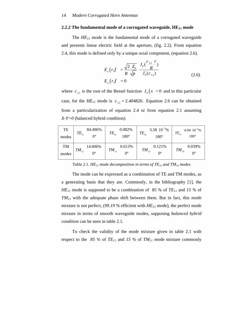
Table 2.1. HE11 mode decomposition in terms of TE1n and TM1n modes
The mode can be expressed as a combination of TE and TM modes, as
a generating basis that they are. Commonly, in the bibliography [1], the
HE11 mode is supposed to be a combination of 85 % of TE11 and 15 % of
TM11 with the adequate phase shift between them. But in fact, this mode
mixture is not perfect, (99.19 % efficient with HE11 mode), the perfect mode
mixture in terms of smooth waveguide modes, supposing balanced hybrid
condition can be seen in table 2.1.
To check the validity of the mode mixture given in table 2.1 with
respect to the 85 % of TE11 and 15 % of TM11 mode mixture commonly
(2.6)
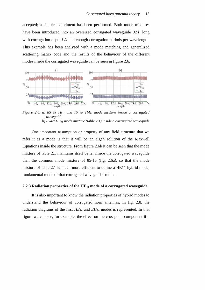
Corrugated horn antenna theory 15
accepted; a simple experiment has been performed. Both mode mixtures
have been introduced into an oversized corrugated waveguide 32·λ long
with corrugation depth λ/4 and enough corrugation periods per wavelength.
This example has been analysed with a mode matching and generalized
scattering matrix code and the results of the behaviour of the different
modes inside the corrugated waveguide can be seen in figure 2.6.
Figure 2.6. a) 85 % TE11 and 15 % TM11 mode mixture inside a corrugated
waveguide b) Exact HE11 mode mixture (table 2.1) inside a corrugated waveguide
One important assumption or property of any field structure that we
refer it as a mode is that it will be an eigen solution of the Maxwell
Equations inside the structure. From figure 2.6b it can be seen that the mode
mixture of table 2.1 maintains itself better inside the corrugated waveguide
than the common mode mixture of 85-15 (fig. 2.6a), so that the mode
mixture of table 2.1 is much more efficient to define a HE11 hybrid mode,
fundamental mode of that corrugated waveguide studied.
2.2.3 Radiation properties of the HE11 mode of a corrugated waveguide
It is also important to know the radiation properties of hybrid modes to
understand the behaviour of corrugated horn antennas. In fig. 2.8, the
radiation diagrams of the first HE1n and EH1n modes is represented. In that
figure we can see, for example, the effect on the crosspolar component if a

Modern Corrugated Horn Antennas 16
EH1n mode is excited inside a corrugated horn. Or also from the same
figure, the excellent radiation properties of the HE11 with nearly null
crosspolar component and with a radiation diagram with quite low sidelobes
can be observed.
The HE11 fundamental corrugated waveguide hybrid mode is then an
excellent mode for radiation purposes. For a common corrugated horn with
oversized aperture, the radiated crosspolarized level will be very low, the
aperture illumination efficiency will be high and the sidelobe level will be
also quite low, (fig. 2.7).
Figure 2.7. Radiation properties of the HE11 hybrid mode against aperture
diameter (D)
From figure 2.7 we can extract several radiation properties of the HE11
hybrid mode:
• It can seen that as aperture diameter (Dapert) increases, and more
smooth waveguide modes appear in propagation, the
crosspolarized component decreases, as it was predicted for
equation 2.1, as well as directivity and sidelobe level increase.

Corrugated horn antenna theory 17
• For big apertures (which implies big directivities (>20 dB)), there
is a sidelobe level limit. For a corrugated horn antenna with a pure
HE11 mode at its aperture and an achieved directivity bigger than
20 dB, is not possible to lower the sidelobe level more than -28 dB.
The theoretical sidelobe level limit for huge directivities is –
27.5 dB.
• Sidelobe levels below –35 dB can be obtained for aperture values
below D=2.25·λ, but the maximum achievable directivity for this
case is 15.4 dB.
• For low level radiated crosspolarized component (<-40 dB), at
least three smooth waveguide modes must be present, (TE11, TM11
and TE12) so a horn aperture diameter of at least D=1.7·λ is
needed1.
Also from fig. 2.7, it can be seen that theoretically, the frequency that
implies exactly D=1.697·λ will have a big amount of crosspolarized
component. This is due to that diameter is just the cut-off diameter for TE12
smooth waveguide mode. Furthermore, at the cut off frequencies of smooth
waveguide modes, crosspolarization spikes can be seen.
As a final conclusion of the radiation properties of the HE11 hybrid
mode, it can be said that this mode is an excellent mode to be excited at the
aperture of a corrugated waveguide, and it offers low crosspolar levels and
quite low sidelobe levels. However, if very low sidelobes are required for a
high restrictive antenna, and its necessary to maintain low crosspolar levels,
1 Furthermore, with a horn aperture diameter similar to D=1.2·λ (between 1.13·λ and
1.22·λ) just where the TE11 mode is alone at the aperture and the TM11 mode is just below cut-off, a quite good crosspolarized component (<-30 dB) can be obtained but only for a very small bandwidth [1] and also with directivities below 11.5 dB.

Modern Corrugated Horn Antennas 18
we need several higher order HE1n modes to be present at the aperture of the
horn (see fig. 2.8) with appropriate amplitude and phase shift between them.
Figure 2.8. Radiation properties of several HE1n and EH1n modes

Corrugated horn antenna theory 19
2.3 Paraxial free space modes (Gaussian modes) and their
relation to waveguide modes.
It is well known that one of the best ways to define a free space
radiation from an antenna is by means of the paraxial free space modes, the
gaussian modes, which are a solution of the paraxial free space equation. A
complete theory about properties of gaussian modes can be found on
appendix I.
Figure 2.9. Propagation of a fundamental gaussian beam mode
The main mode for our corrugated horn radiation purposes is the
fundamental gaussian mode. This mode has null crosspolarisation and null
sidelobes. Its electric field propagation formula can be seen in equation 2.7:
2 2
2 ( ( ))( ) 2 ( )0( , , )( )
r krj
j kz zw z R zwE r z e e e
w zζϕ
−−
− −⋅= ⋅ ⋅ ⋅
where r2 = x2+ y2 and w(z) is the beamwidth where there is a field decay of
1/e respect to the maximum, (see figure 2.9). In z = 0, the function w(z),
(see equation 2.8), has a minimum known as beamwaist and called w0.
2
00
2( ) 1
zw z w
k w ⋅
= ⋅ + ⋅
(2.7)
(2.8)
Modern Corrugated Horn Antennas 20
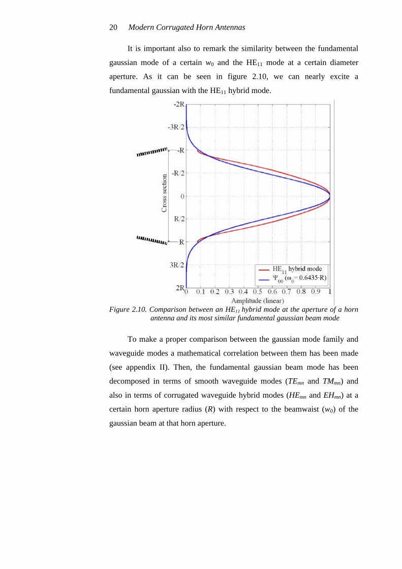
It is important also to remark the similarity between the fundamental
gaussian mode of a certain w0 and the HE11 mode at a certain diameter
aperture. As it can be seen in figure 2.10, we can nearly excite a
fundamental gaussian with the HE11 hybrid mode.
Figure 2.10. Comparison between an HE11 hybrid mode at the aperture of a horn
antenna and its most similar fundamental gaussian beam mode
To make a proper comparison between the gaussian mode family and
waveguide modes a mathematical correlation between them has been made
(see appendix II). Then, the fundamental gaussian beam mode has been
decomposed in terms of smooth waveguide modes (TEmn and TMmn) and
also in terms of corrugated waveguide hybrid modes (HEmn and EHmn) at a
certain horn aperture radius (R) with respect to the beamwaist (w0) of the
gaussian beam at that horn aperture.

Corrugated horn antenna theory 21
Figure 2.11. a) Fundamental gaussian mode decomposition in terms of TE and TM
b) Fundamental gaussian mode decomposition in terms of HE and EH
From figure 2.11 we can see that the fundamental gaussian mode can
be expressed completely as a combination of TE1n and TM1n smooth
waveguide modes and also as a combination of HE1n hybrid modes.
At this point, it should be noted that HE11 mode has been always
known as a gaussian-like mode because its field is nearly a pure gaussian, in
fact it is up to 98.1 % efficient with a fundamental gaussian beam of
R/w0=1.554 (w0/R=0.6435) (see figures 2.10 and 2.11b). To obtain at the
aperture of a corrugated horn antenna a high efficient fundamental gaussian
beam mode (this implies lower sidelobes), more hybrid modes must be
present at the horn aperture as it was said in section 2.2. This aspect will be
covered in the following chapters, [7,8].
2.4 References.
[1] A.D. Olver, P.J.B. Clarricoats, A.A. Kishk and L. Shafai, “Microwave
Horns and Feeds”, IEE Electromagnetic waves series 39, The Institution
of Electrical Engineers, 1994.

Modern Corrugated Horn Antennas 22
[2] P.D. Potter, “A new horn antenna with suppressed sidelobes and equal
beamwidths”, Microwave Journal, 1963, 6, pp. 71-78.
[3] Clarricoats, P.J.B. and Olver, A.D., “Corrugated Horns for Microwave
Antennas”, IEE Electromagnetic waves series 39, The Institution of
Electrical Engineers, 1984.
[4] Clarricoats, P.J.B., Saha, P.K. and Tech. M, “Propagation and Radiation
behaviour of corrugated feeds”, IEE Proceedings, September 1971, Vol.
118, Nº 9.
[5] Zhang, X., “Design of Conical Corrugated Feed-Horns for Wide-Band
High-Frequency Applications”, IEEE Transactions on Microwave
Theory and Techniques, August 1993, vol. 41, n. 8.
[6] S. Ramo, J.R. Whinnery, T. van Duzer, “Fields and Waves in
Communication Electronics”, John Wiley & Sons, Inc.1994.
[7] Del Río C., “Diseño de guías de onda cuasi-ópticas para modos
gaussianos de orden superior”, Ph. D. dissertation, Escuela Técnica
Superior de Ingenieros Industriales y de Ingenieros en
Telecomunicación, Public University of Navarra, (UPNA), November
1996
[8] Carlos del Río, Ramón Gonzalo, Mario Sorolla and Manfred Thumm,
“Antenas de Bocina Conversoras de Modos de Guía de Onda a
Estructuras Gaussianas”, Spanish Patent N. P.9501922 Public
University of Navarra, (UPNA), September 1995.

Chapter 3
Conical corrugated horn antennas
The design of circular horn antennas has been based, for a long time,
in the control of the guide mode mixture to excite an HE11 circular
corrugated waveguide mode. It is well known from the previous chapter that
this hybrid mode can be made up of approximately a combination of
85% TE11 and 15% TM11 smooth circular waveguide modes with an
appropriate relative phasing between them. The starting field distribution is
usually the TE11 mode of the circular waveguide under monomode
operation, and by means of a proper step or taper in the horn radius, the
right amount of TM11 (amplitude and phase) is excited (Potter type horns)
[1,2,3].
This technique, firstly used in non-oversized horns, was later extended
to oversized ones, using long and smooth conical tapers after the step, which
provided the appropriate mode mixture at the aperture (85%-15%). To get
this mixture with nice radiating features, two main parameters have to be
considered: the output diameter and the horn length. Since the coupling
coefficient between waveguide modes is directly related to the waveguide
slope change, for a given output radius that fixes the desired beamwidth, the
change in horn length allows the designer to select the appropriate phasing
in the 85% of TE11 and 15% of TM11 mode mixture obtaining the
appropriate sidelobe and crosspolarization minimum levels. Therefore, the
only parameter to adjust is the taper length. This type of horn antennas were
extensively used in the past decades and were known as Potter type horns,

Modern Corrugated Horn Antennas 24
[1]. Its drawback was the reduced bandwidth a design of this type could
cover.
Another technique is based on corrugated circular waveguides and
takes profit of the fact that this mode mixture corresponds to the
fundamental mode of a circular corrugated waveguide, the HE11 mode. This
technique reported in [2,3,4,5] involves a gradual matching of the smooth
circular guide to another corrugated one wherein the corrugation depth is
smoothly tapered from λ/2 to λ/4.
These two outlined techniques are combined in the so-called conical
corrugated horn antennas with a matching device at their input port. In
principle, corrugated horn antennas presents a wider frequency response
than Potter type horns. Their design parameters are basically: corrugation
parameters (period, duty cycle, depth, shape, etc...); length and profile of the
λ/2-to-λ/4 impedance matching device; and the horn geometry in order to
optimise the global performance of the horn.
Directivity, gain, sidelobe and crosspolarization levels are important
design parameters for many applications involving horn antennas.
Additional design parameters, relevant to satellite applications are length
and weight, which need to be minimized, [6,7].
During the last 20 years, many of the applications involving high
performance horn antennas have been equipped with conical corrugated
horn antennas.
Conical corrugated horn antennas are one of the best possibilities to
accomplish very high radiation pattern requirements; but during the last
decade another shorter and better profiles for corrugated horn antennas have
aroused. Nevertheless, a brief review of the way of designing conical

Conical corrugated horn antennas 25
corrugated horn antennas has been summarized in the following paragraphs.
This simple design method will help in the understanding of modern
corrugated horn antenna design for the rest of this thesis.
In this chapter, only moderate directivity antennas (above 15 dB) for
high performance applications will be covered.
3.1 Conical corrugated horn antenna design
Among the specifications detailed for the design of a corrugated horn
antenna, there is an specially important parameter, the directivity needed for
the design, or more specifically, the edge taper of the radiation pattern at a
certain angle (copolar beamwidth).
Figure 3.1. Conical corrugated horn antenna
So, once we have defined the directivity of the design and assumed at
the aperture an HE11 mode (85% TE11 + 15% TM11 approximately), the
output radius of the conical corrugated horn antenna is nearly fixed from a
physical point of view.
For normal conical corrugated horn antenna design, there are several
diagrams for –3 dB and –10 dB half beamwidth that define the copolar
pattern in terms of the profile angle and the aperture diameter, [3]. A version
of these diagrams has been depicted in figures 3.2a and 3.2b. On the other

Modern Corrugated Horn Antennas 26
hand, if our design parameter is the directivity we can select the aperture
diameter of the antenna with the aid of figure 3.3a.
Figure 3.2. a) –3 dB design curve for conical corrugated horn antennas
b) –10 dB design curve for conical corrugated horn antennas
Usually, for moderate to high directivities (>18 dB) and high
performance, the profile angle will be below 20 degrees. As we decrease
this angle, the antenna becomes longer for a given directivity, but its
radiation pattern becomes more perfect. The profile angle is usually defined
by the maximum sidelobe level and beam purity allowed for the design, (see
figures 3.3b and 3.4).
Figure 3.3. a) Directivity design curves for conical corrugated horns antennas
b) Max. sidelobe level design curves for conical corrugated horns
Conical corrugated horn antennas 27
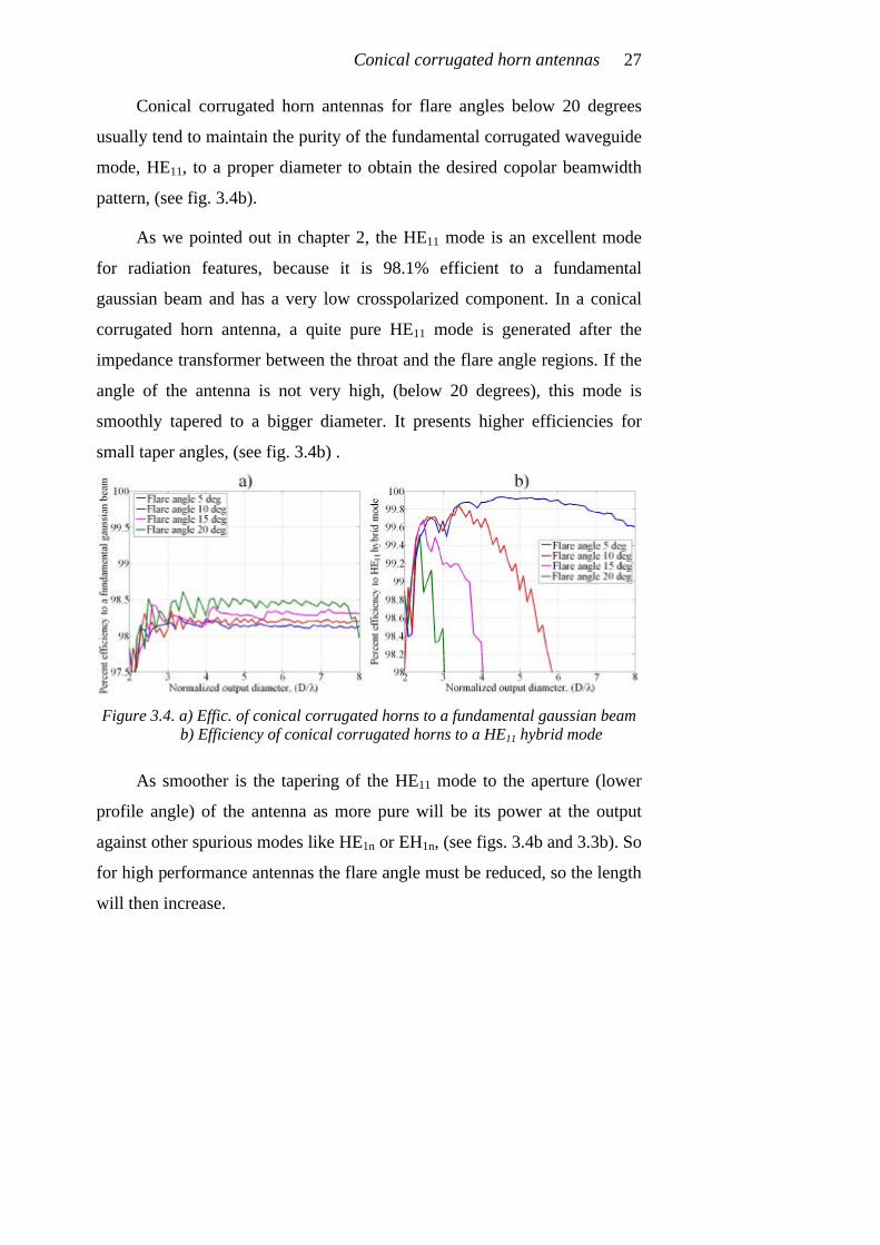
Conical corrugated horn antennas for flare angles below 20 degrees
usually tend to maintain the purity of the fundamental corrugated waveguide
mode, HE11, to a proper diameter to obtain the desired copolar beamwidth
pattern, (see fig. 3.4b).
As we pointed out in chapter 2, the HE11 mode is an excellent mode
for radiation features, because it is 98.1% efficient to a fundamental
gaussian beam and has a very low crosspolarized component. In a conical
corrugated horn antenna, a quite pure HE11 mode is generated after the
impedance transformer between the throat and the flare angle regions. If the
angle of the antenna is not very high, (below 20 degrees), this mode is
smoothly tapered to a bigger diameter. It presents higher efficiencies for
small taper angles, (see fig. 3.4b) .
Figure 3.4. a) Effic. of conical corrugated horns to a fundamental gaussian beam
b) Efficiency of conical corrugated horns to a HE11 hybrid mode
As smoother is the tapering of the HE11 mode to the aperture (lower
profile angle) of the antenna as more pure will be its power at the output
against other spurious modes like HE1n or EH1n, (see figs. 3.4b and 3.3b). So
for high performance antennas the flare angle must be reduced, so the length
will then increase.

Modern Corrugated Horn Antennas 28
But, the efficiency to the fundamental free space mode (fundamental
gaussian) is not very high for a conical corrugated horn antenna (around
98.1 % efficient to a fundamental gaussian beam for a pure HE11 hybrid
mode), see figure 3.4a. Then, the sidelobe level for a conical corrugated
horn antenna with moderate directivities (above 20 dB) cannot be lowered
below –30 dB, (see figure 3.3b and figure 2.7).
In figure 3.3b, a picture of sidelobe level against flare angle and output
diameter is depicted. Shoulders are considered as sidelobes in that figure
because they broaden the radiation pattern.
In figure 3.5 a picture of the phase center position inside a conical
corrugated horn antenna against flare angle is depicted. Phase center moves
closer to the aperture of the antenna as flare angle decreases, that means that
output aperture diameter is more efficiently illuminated, so directivity
increases a little for smaller flare angles as can be seen in figure 3.3a.
Figure 3.5. Phase center position in a conical corrugated horn antenna against
flare angle of the profile
Phase center position is a very important horn antenna design
parameter because it allocates the source for the free space radiation, (the
Conical corrugated horn antennas 29
beamwaist of the gaussian mode propagation or the point where the phase
fronts are planar), see appendix I.
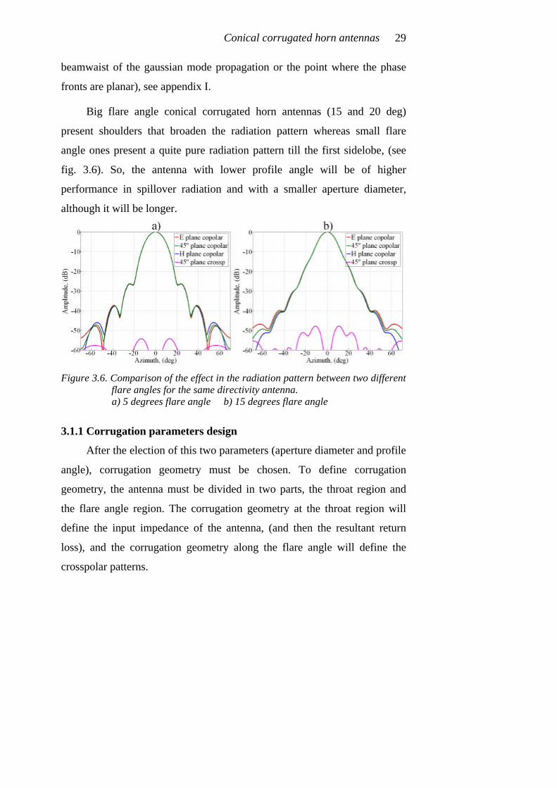
Big flare angle conical corrugated horn antennas (15 and 20 deg)
present shoulders that broaden the radiation pattern whereas small flare
angle ones present a quite pure radiation pattern till the first sidelobe, (see
fig. 3.6). So, the antenna with lower profile angle will be of higher
performance in spillover radiation and with a smaller aperture diameter,
although it will be longer.
Figure 3.6. Comparison of the effect in the radiation pattern between two different
flare angles for the same directivity antenna. a) 5 degrees flare angle b) 15 degrees flare angle
3.1.1 Corrugation parameters design
After the election of this two parameters (aperture diameter and profile
angle), corrugation geometry must be chosen. To define corrugation
geometry, the antenna must be divided in two parts, the throat region and
the flare angle region. The corrugation geometry at the throat region will
define the input impedance of the antenna, (and then the resultant return
loss), and the corrugation geometry along the flare angle will define the
crosspolar patterns.

Modern Corrugated Horn Antennas 30
Figure 3.7. Return loss of TE11 mode at the throat of different profile angles of
conical corrugated horns against first slot depth a) Throat radius of 0.39·λ b) Throat radius of 0.414·λ c) Throat radius of 0.446·λ d) Throat radius of 0.477·λ
Usually, for a normal corrugated horn antenna, the input mode at the
throat region will be the TE11 smooth circular waveguide mode, this mode
defines approximately the input radius of the corrugated horn antenna
profile. For minimum return loss of this mode, corrugation depth at the
throat region must be around λ/2, (see figure 3.7).
After an analysis of figure 3.7, we can conclude that depending on the
value of the input radius and the angle of the conical corrugated profile, the
best possible value of the first corrugation depth can change and be slightly

Conical corrugated horn antennas 31
different of λ/2, in fact as it can be seen the best possible value for small
profile angles is usually slightly above λ/2.
As it has been shown in the previous chapter, for corrugated
structures, for minimum crosspolarization, (balanced hybrid condition),
corrugation depth must be around λ/4. Therefore, along our corrugated horn
antenna, in order to satisfy both conditions, good impedance matching at the
throat and low crosspolar levels, a tapered change in corrugation depth
between the throat region and the flare angle region is then necessary.
A new parameter controlling the compromise between matching and
radiation features appears, the length of this λ/2 to λ/4 input waveguide
transformer.
Figure 3.8. Detail of a λ/2 to λ/4 impedance transformer at the throat of a
corrugated horn antenna
If the return loss must be improved, a longer transformer should be
necessary, but if the crosspolar level is the critical specification a shorter
impedance transformer could be chosen. In general, the length of this
transformer will be defined as the length from the throat to the point where
TM11 mode start to be propagating at the inner antenna part of the
corrugation. A linear taper for the transformation between λ/2 and λ/4 is
usually chosen, (see figure 3.8).

Modern Corrugated Horn Antennas 32
The number of corrugations per wavelength (p) must be usually above
three at the lowest frequency of the necessary bandwidth, but it is not
usually necessary to use more than five corrugations per wavelength, as it
will be seen in appendix II. This parameter complicates a lot the
manufacturing process for the antenna if many corrugations per wavelength
are needed and the frequency of operation is high (i.e. millimeter waves),
and can also be counterproductive for return loss at lower band frequencies.
Corrugation slot width (w) is usually chosen thinner than half
corrugation period, but it is usually not necessary to reach really thin widths
for a good performance, and this also provides an easier manufacturing
process.
3.2 Design of a 22 dB conical corrugated horn antenna
As a practical example of how to design a conical corrugated horn
antenna, let’s say that we want to design a 22 dB directivity conical
corrugated horn antenna with sidelobes lower than –25 dB and as low return
loss and crosspolar level as possible in the most compact profile.
Figure 3.9. Directivity design curves for conical corrugated horns antennas

Conical corrugated horn antennas 33
To design this antenna, we make a zoom of figure 3.3a in figure 3.9.
From this figure we see that we can design a 5 degrees profile angle antenna
with a 4.8·λ aperture diameter or a 10 degrees profile angle antenna with a
5·λ aperture diameter or a 15 degrees profile angle antenna with a 5.4·λ
aperture diameter. Having a look at figure 3.3b we can fill a table with this
parameters as well as sidelobe level and required length for each of the
profile angles, (see table 3.1).
Profile angle (deg)
Directivity, (dB)
Input radius
Aperture diameter Length Phase
center
Sidelobe level, (dB)
5 deg 22 dB 0.39·λ 4.8·λ 23·λ 1.85·λ -26.5 dB
10 deg 22 dB 0.39·λ 5·λ 12·λ 3.42·λ -21.7 dB
Table 3.1. 22 dB conical corrugated horn antenna design parameters
Selecting an input radius such as the one in figure 3.4a1,
(rthroat=0.39·λ), and having a look at table 3.1; we can select approximately a
profile angle of 6 degrees or perhaps 7 degrees to achieve the –25 dB
sidelobe level requirement.
Analyzing carefully the antenna the result leads to an antenna of
6.6 deg taper profile with the first corrugation depth of 0.52·λ decreasing
linearly with an impedance transformer of 1.9·λ long to a corrugation depth
for the rest of the antenna of 0.25·λ, see figure 3.10. The corrugation
parameters have been selected as p=λ/5 and w=p/3.
The resultant length of the profile is 17.8·λ. It is really a quite long
antenna for 22 dB directivity. This length cannot be shortened if we must
1 An input radius of 0.39·λ is one of the monomode input radius most widely used for waveguide standards. λ is considered to be the wavelength in the middle of the band.

Modern Corrugated Horn Antennas 34
have the sidelobe level at –25 dB or less by any method if we maintain the
conical corrugated profile.
Figure 3.10. Conical corrugated horn antenna design for 22 dB directivity and
-25 dB maximum sidelobe level
What would happen if we need to design a 22 dB directivity antenna
but with the sidelobe level below for example -35 dB? The answer using a
conical corrugated horn will be simple: a conical corrugated horn antenna
with a directivity above 16 dB can never have a sidelobe level below
-35 dB, (see figure 2.7) and exactly at 22 dB directivity a sidelobe level
below –28 dB is also impossible. But there are other possibilities to solve
this problem: we could use other corrugated horn profile to improve the
sidelobe level and reduce the length. At this point is where we designed and
patented in the year 1995 the gaussian profiled horn antenna, (GPHA) [8].
But this will be the topic covered in the next chapter.

Conical corrugated horn antennas 35
3.3 References.
[1] Potter, P. D., "A New Horn Antenna with Suppressed Sidelobes and
Equal Beamwidths", Microwave Journal, vol. VI, June 1963, pp. 71-78.
[2] Clarricoats, P.J.B. and Olver, A.D., "Corrugated Horns for Microwave
Antennas", IEE Electromagnetics Waves Series 18, Chap. 5, 6 and 7,
Peter Peregrinus, 1984.
[3] A.D. Olver, P.J.B. Clarricoats, A.A. Kishk and L. Shafai, “Microwave
Horns and Feeds”, IEE Electromagnetic waves series 39, The Institution
of Electrical Engineers, 1994.
[4] G.L. James, “Analysis and design of TE11 to HE11 corrugated cylindrical
waveguide mode converters”, IEEE Transactions on Microwave Theory
and Techniques, Vol. MTT-29, pp. 1059-1066, 1981.
[5] B. Maca, Thomas, G.L. James and K.J. Greene, “Design of high-
performance wideband corrugated horns for Cassegrain antennas”, IEEE
Transactions on Antennas and Propagation, Vol. AP-34, pp. 750-757,
1986.
[6] G.L. James, “Design of wide-band compact corrugated horns”, IEEE
Transactions on Antennas and Propagation, Vol. AP-32, pp. 1134-1138,
1984.
[7] C. Granet, T.S. Bird and G.L. James, “Compact low-sidelobe corrugated
horn for global earth coverage”, Proceedings of the IEEE Antennas and
Propagation International Symposium and URSI Radio Science
Meeting, Orlando, Florida, 11-16 July 1999, pp. 712-715.
[8] Carlos Del Río, Ramón Gonzalo, Mario Sorolla and Manfred Thumm,
“Antenas de Bocina Conversoras de Modos de Guía de Onda a

Modern Corrugated Horn Antennas 36
Estructuras Gaussianas”, Spanish Patent. N. P.9501922 Public
University of Navarra, (UPNA), September 1995.

Chapter 4
Corrugated Gaussian Profiled Horn
Antenna design
Gaussian Profiled Horn Antennas (GPHA’s) were firstly proposed in
the year 1995 during the research developed in [1,2]. Those GPHA’s were
smooth waveguide horns that optimized the conversion between the smooth
circular waveguide mode TE01 (at the input of the antenna) to the gaussian
mode Ψ01 (at the aperture of the antenna) with a really nice conversion
efficiency (above 99%). As gaussian modes are the solution of the paraxial
wave equation for free space (see appendix I) every radiation which is
propagated in free space can be decomposed in terms of gaussian modes1.
By using these horn antennas, the matching between the waveguide
and the free space is almost perfect, being the most "natural" way to match
the two media. From a waveguide mode or mode mixture, what the GPHA’s
do is to excite a very similar transversal field distribution with Gaussian
propagating features.
Most of the applications in telecommunication, telecontrol and
telemetric systems deal with the fundamental gaussian mode Ψ00 as the
main free space mode of a modern radiation pattern. To obtain a high purity
Ψ00 mode at the aperture of a horn antenna, the corrugated version of the
GPHA’s developed in [3] aroused. The introduction of the corrugated
GPHA becomes very useful to address the most stringent requirements in
1 Only the radiation that complies with the paraxial condition which is the case of all the
radiation from the antennas we are going to consider in this thesis.
Modern Corrugated Horn Antennas 38
directivity, gain, sidelobe and crosspolarization levels as well as reducing
the total length and weight of the resultant profile.
The design procedure for a corrugated GPHA starts like in a conical
corrugated horn with a detailed list of specifications; directivity, maximum
allowable crosspolar level, sidelobe level, return loss… But unlike for
conical corrugated horn antenna design, corrugated GPHA design follows a
completely different path, as it will be seen in the following paragraphs.
It will be shown that with these new profiles we can improve
important far field radiation pattern features of any existing conical horn,
like sidelobe levels, while keeping its other far field characteristics, by
adding some part of a GPHA at its end.
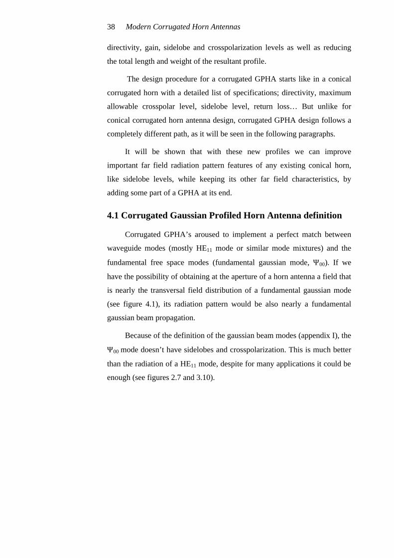
4.1 Corrugated Gaussian Profiled Horn Antenna definition
Corrugated GPHA’s aroused to implement a perfect match between
waveguide modes (mostly HE11 mode or similar mode mixtures) and the
fundamental free space modes (fundamental gaussian mode, Ψ00). If we
have the possibility of obtaining at the aperture of a horn antenna a field that
is nearly the transversal field distribution of a fundamental gaussian mode
(see figure 4.1), its radiation pattern would be also nearly a fundamental
gaussian beam propagation.
Because of the definition of the gaussian beam modes (appendix I), the
Ψ00 mode doesn’t have sidelobes and crosspolarization. This is much better
than the radiation of a HE11 mode, despite for many applications it could be
enough (see figures 2.7 and 3.10).
Corrugated Gaussian Profiled Horn Antenna design 39
Figure 4.1. Fundamental gaussian mode approximation at the aperture of a
corrugated horn antenna
The Gaussian beam modes are a solution of the paraxial wave equation
in the free space [3]. Any paraxial radiation from a waveguide can be
understood as an infinite summation of Gaussian beam modes, since they
are orthogonal and therefore can generate a basis in free space. The
conceptual idea involves the generation of any kind of transversal field
distribution having Gaussian radiation features. Feeding a GPHA with
several appropriate field distributions (i.e., TE0m, HE11 circular waveguide
modes), we can excite very efficiently a pure Gaussian beam mode.
The profile of a GPHA is defined basically by the expansion formula
of the gaussian beam modes. So, the Gaussian beam broadening (decay of
fields to 1/e of the central value) is given by:

Modern Corrugated Horn Antennas 40
2
0 20
2 z(z)= 1+
k ⋅
ϖ ϖ ⋅ ⋅ϖ
where ϖ0 is the beamwaist at z=0 and k=2π/λ is the wavenumber in free
space. The corresponding waveguide profile which follows the curve for
Gaussian equi-amplitude relative surfaces is given by,
2
2
00 22
20 0
D2 z zR(z) r 1 1
k 2 D2
⋅ λ ⋅ = ⋅ + = ⋅ + ⋅ϖ π⋅α ⋅
where r0=D0/2 is the input radius of the corrugated profile and
ϖ0=α·r0=α·D0/2 is the beamwaist value at z=0 related with the D0 through
the parameter α. The α parameter controls the aperture angle of the horn for
a given frequency and waveguide radius. D0 is the input diameter. Figure
4.2 shows the relationship between the horn profile (equation 4.2) and the
beamwaist propagation imposed by equation 4.1.
Figure 4.2. Corrugated Gaussian Profiled Horn Antenna, (corrugated GPHA)
The input field distribution to a corrugated GPHA could be anyone
with a controlled diffraction. In principle, any waveguide mode or mixture
of waveguide modes with low amplitude near the metallic walls is suitable
(4.1)
(4.2)

Corrugated Gaussian Profiled Horn Antenna design 41
to feed a corrugated GPHA, but if we want to obtain a high purity
fundamental gaussian beam a HE11 mode is one of the best solutions. The
forward scattered fields will have the same transversal amplitude
distribution as the original ones but with Gaussian broadening properties.
For instance, if a smooth circular waveguide excited in its TE01 mode
is used as input to the GPHA, the forward scattered field will be a hollow
beam azimuthally polarized expanding its width as a Gaussian field
structure, (Ψ01 gaussian mode) [4]. Alternatively, to properly excite the
fundamental Gaussian beam, (Ψ00 gaussian mode), one should use
something like the HE11 mode from a corrugated circular waveguide
[5,6,7,8,9].
4.2 Gaussian profiled corrugated horn antenna design
The corrugated GPHA to generate gaussian field structures can be
applied to any kind of waveguide cross sections. In this thesis, only circular
waveguides have been analyzed, but similar conclusions could be obtained
for rectangular, square or any arbitrary waveguide cross section [10].
In this chapter, we are going to analyze the oversized operation [3,5],
wherein the radiation features of almost any horn antenna or TE11 to HE11
mode converter can be improved by addition of a corrugated GPHA section
at its end.
The corrugated GPHA feed mode will be the HE11 mode. So we will
assume that the horn antenna or antenna converter just behind the
corrugated GPHA provide us a quite perfect HE11 mode at its end. We could
use, for example, a conical corrugated horn antenna or other shorter
possibilities that will be covered in the chapter 5 of this thesis.

Modern Corrugated Horn Antennas 42
To design a corrugated GPHA, we have three main design parameters
(see equation 4.2); profile length (L), input diameter (Din) and the alpha
parameter of the profile (α). In figure 4.3 we can see how this parameters
affect to the profile shape.
Figure 4.3. Corrugated GPHA main design parameters
To define the beamwidth of the radiation pattern of a corrugated
GPHA we must select the value of D0, not the value of the output aperture
diameter (Dapert) as in a conical corrugated horn design of chapter 3. Thus,
for a given directivity or beamwidth, we could fix quite approximately the
value of D0. Then, there are still two more parameters to play with: the
profile length, (L), and the alpha parameter of the profile, (α).
Fixing the length to be enough to extract the main radiation parameters
(approximately, L=[3.5·D0/λ-5]·λ) and changing the alpha parameter, we
could modify slightly the final directivity of the GPHA section (see figure
4.4).
Corrugated Gaussian Profiled Horn Antenna design 43
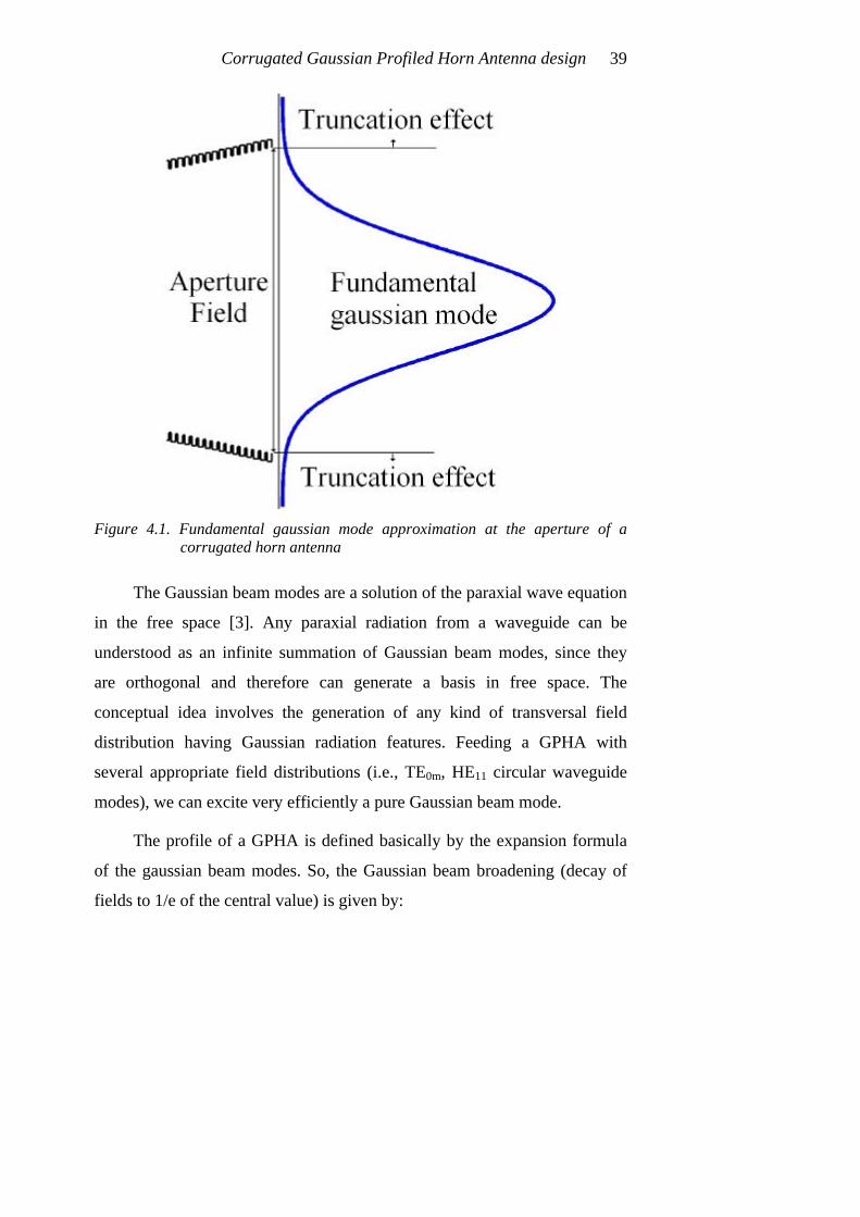
Figure 4.4. Beamwidth definition of the radiation pattern of a corrugated GPHA in
terms of α a) –3 dB half beamwidth curves b) –10 dB half beamwidth curves c) Directivity curves
In figure 4.4, the –3 dB and –10 dB half beamwidth curves for a
corrugated GPHA have been given. We will use for the rest of the thesis
only directivity curves to define the beamwidth of corrugated GPHA’s
because we think it is clearer. For a comparison of a certain beamwidth with
directivity, a reference to appendix III is needed where the comparison will
be given in some figures assuming a pure fundamental gaussian beam as the
radiation mode2.
2 This assumption is enough because usually the antennas to be designed in this thesis
present pure fundamental gaussian beam decay till at least –25 dB.

Modern Corrugated Horn Antennas 44
Figure 4.5. a) Corrugated GPHA efficiency to a fundamental gaussian beam in
terms of α b) GPHA maximum sidelobe level in terms of α
We have two possibilities or criteria to define the alpha parameter of
the profile, (α): to select the α value that provides the most perfect gaussian
beam at the output (this means minimum sidelobes) or to select the α value
that is not the best for gaussian beam efficiency but gives a little bit more
directive radiation pattern in a smaller output diameter.
The best α value for gaussian beam efficiency is α=0.59 and the best
α value for maximum directivity is α=0.68, see figure 4.5. The main
difference is that with α=0.59 we can easily get sidelobes below –45 dB and

Corrugated Gaussian Profiled Horn Antenna design 45
with α>0.65 the sidelobes will be around -35 dB but with a slightly
improvement in directivity, (around 0.2 dB) and a significant reduction in
aperture diameter.
In figure 4.5 we can also see the great improvement in the radiation
pattern that a corrugated GPHA provides in comparison with the conical
corrugated horn antenna radiation pattern with the HE11 mode at its output
aperture, (see figures 2.7 and 3.10).
The last parameter we must define to completely design the GPHA is
the profile length, L. To define the length of a GPHA we have developed an
empirical formula with a parameter called factor of length, f, see
equation 4.3.
( )2
0 0
00
L D f 1 D
DD
= λ ⋅ ⋅ ⋅ +
= λ
where 0D is the normalized input diameter of the GPHA.
The factor of length, f, can be any number between 0.01 and 0.3. The
bigger is this number, the longer the antenna would be. If the antenna is
very long we can say that we are over-guiding the gaussian beam and the
addition of more antenna length is not really improving the beam, so the
efficiency can be the same than with a shorter antenna. The best value for
very nice gaussian beam efficiency and not excessive length (which means
low sidelobes) is f=0.19 (f=0.19 has been the factor of length selected for
figures 4.4 and 4.5 in fact), but values of f between 0.05 and 0.1 are usually
enough and are the most currently used giving a short profile with not a big
output diameter, see figure 4.6.
(4.3)
Modern Corrugated Horn Antennas 46
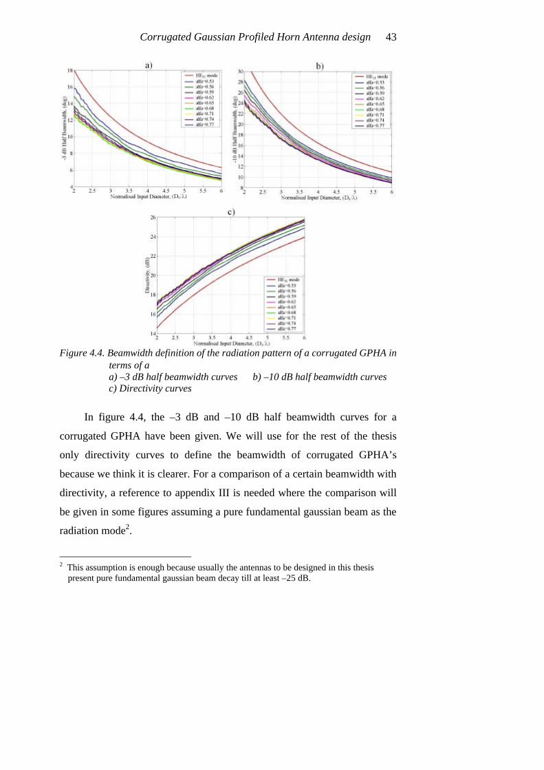
Figure 4.6. a) Corrugated GPHA efficiency to a fundamental gaussian beam in
terms of length (L), α=0.59 b) Corrugated GPHA maximum sidelobe level in terms of L, α = 0.59
From figure 4.6b we can see that a small piece of corrugated GPHA of
a ridiculous length with f = 0.01, can improve quite a lot the radiation
pattern of a conical corrugated horn antenna lowering the sidelobe below
-30 dB. Increasing the length to f = 0.03, the sidelobe level would be below
–35 dB, (to have a reference of the antenna length in terms of the factor of
length f see figure 4.7).

Corrugated Gaussian Profiled Horn Antenna design 47
Figure 4.7. Corrugated GPHA length in terms of factor of length, ( f )
Additionally, if f>0.1 the directivity of a corrugated GPHA has an
improvement of around 1.5 dB higher directivity than the conical corrugated
horn antenna alone (figure 4.8) but with a wider output aperture diameter
indeed.
Figure 4.8. Corrugated GPHA directivity in terms of L, α=0.59

Modern Corrugated Horn Antennas 48
Corrugation parameters of a GPHA are just the same as any other
corrugated horn antenna, corrugation period, p between λ/3 and λ/5 and
corrugation tooth width, w around p/2 are usually nice corrugation
parameters, see appendix II.
There is only one parameter left in the corrugated GPHA design; what
will be the phase center position in a corrugated GPHA?
We know that in a conical corrugated horn antenna, the phase center
position if the profile angle is below 10 degrees which is usually normal,
will be quite near the radiation aperture. But in a corrugated GPHA, the
phase center is more inside the horn antenna than in the conical counterpart.
Its position depends a lot on the α value of the corrugated GPHA as it can
be seen in figure 4.9. As we will see in the rest of this thesis, to have a phase
center position inside the horn antenna gives a better stability of this
parameter in a wider bandwidth but provides a worse aperture size to
directivity ratio than a conical corrugated horn, that’s the price that a better
radiation pattern must pay.
Figure 4.9. GPHA phase center position in terms of α, f = 0.19

Corrugated Gaussian Profiled Horn Antenna design 49
From figure 4.9, the bigger is the α value, the nearer the phase center
to the antenna aperture will be. So this means that if α is bigger, the antenna
opens to free space slower, so the fields inside are guided (not radiated) and
the phase center moves to the aperture.
4.3 Gaussian profiled corrugated horn antenna performance
Till now we have assumed that at the input of a corrugated GPHA we
have a pure HE11 mode but, what would happen if the HE11 mode is not so
ideal? Will the GPHA still have the nice radiation properties we studied in
the last paragraphs?
Figure 4.10. GPHA performance (α=0.59, f=0.19) under HE11 impurities of HE12
a) Efficiency to a fundamental gaussian beam b) Max. sidelobe level (shoulders above 10º are considered sidelobes3)
An study of the impurity allowed for the HE11 mode at the input
aperture of a corrugated GPHA was made for one of them of α=0.59 and
f =0.19. To define the impurity of a HE11 mode is rather difficult, but to
have an impression of what happens, we made a sweep of a mixture of HE11
and HE12 at the input aperture of the GPHA. In fact, the sweep was made 3 The degree level of a shoulder is defined as the difference in the slope between the
no-shoulder estimated slope of the radiation pattern and the resultant slope at the inflexion point of that shoulder
Modern Corrugated Horn Antennas 50
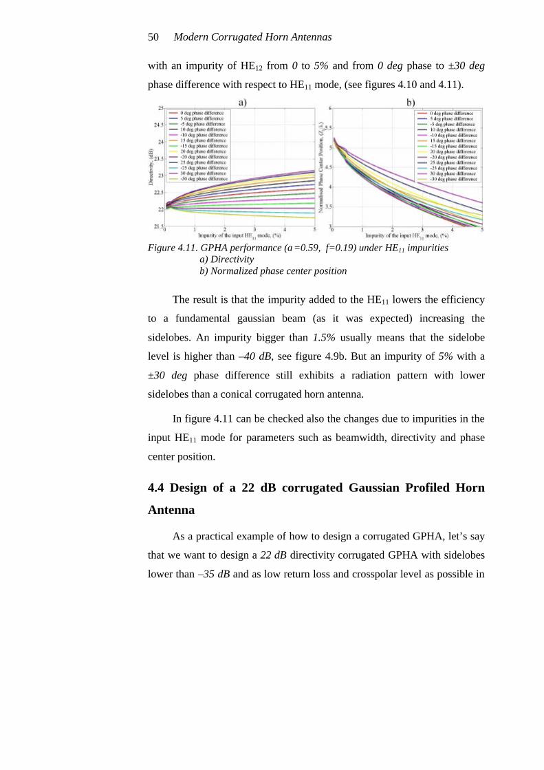
with an impurity of HE12 from 0 to 5% and from 0 deg phase to ±30 deg
phase difference with respect to HE11 mode, (see figures 4.10 and 4.11).
Figure 4.11. GPHA performance (α=0.59, f=0.19) under HE11 impurities
a) Directivity b) Normalized phase center position
The result is that the impurity added to the HE11 lowers the efficiency
to a fundamental gaussian beam (as it was expected) increasing the
sidelobes. An impurity bigger than 1.5% usually means that the sidelobe
level is higher than –40 dB, see figure 4.9b. But an impurity of 5% with a
±30 deg phase difference still exhibits a radiation pattern with lower
sidelobes than a conical corrugated horn antenna.
In figure 4.11 can be checked also the changes due to impurities in the
input HE11 mode for parameters such as beamwidth, directivity and phase
center position.
4.4 Design of a 22 dB corrugated Gaussian Profiled Horn
Antenna
As a practical example of how to design a corrugated GPHA, let’s say
that we want to design a 22 dB directivity corrugated GPHA with sidelobes
lower than –35 dB and as low return loss and crosspolar level as possible in

Corrugated Gaussian Profiled Horn Antenna design 51
the most compact profile. The design specifications are the same that the
ones in 3.3 section except that we want the sidelobe level 10 dB lower for
the corrugated GPHA.
To design the corrugated GPHA we must have a look to figures 4.6b
and 4.8. The best value that gives the most compact design seems to be for
α=0.59 and f=0.025 for an input diameter of 4.49·λ. The corrugation
parameters chosen are: d=λ/4, p=λ/5 and w=p/3. With this values, the
corrugated GPHA would be 3.4·λ long and with an output diameter of
5.22·λ.
The output diameter is a little bit larger than for the conical antenna
design in section 3.3, and the total length can not be yet compared because
we assume a pure HE11 at the input of the corrugated GPHA, and a TE11 to
HE11 transformer should be included for a correct comparison, (see chapter
6 for a comparison). To reduce the output diameter of the GPHA we could
use a bigger α value and a little bit longer profile to achieve the same
-35 dB sidelobe level. For example an α=0.64 with an f=0.034 for an input
diameter of 4.47·λ. can be used to obtain the –35 dB sidelobe level as well,
and this design presents a length of 3.8·λ and an output diameter of 5.17·λ.
The difference is small in the output diameter compared to the length
increase, so the first design with α=0.59 is going to be selected.
In the next chapter (chapter 5) an analysis different models of TE11 to
HE11 mode converters will be studied. A perfect comparison between
conical corrugated horn antennas and corrugated GPHA’s will be carried out
in chapter 6.
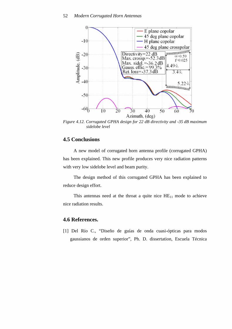
Modern Corrugated Horn Antennas 52
Figure 4.12. Corrugated GPHA design for 22 dB directivity and -35 dB maximum
sidelobe level
4.5 Conclusions
A new model of corrugated horn antenna profile (corrugated GPHA)
has been explained. This new profile produces very nice radiation patterns
with very low sidelobe level and beam purity.
The design method of this corrugated GPHA has been explained to
reduce design effort.
This antennas need at the throat a quite nice HE11 mode to achieve
nice radiation results.
4.6 References.
[1] Del Río C., “Diseño de guías de onda cuasi-ópticas para modos
gaussianos de orden superior”, Ph. D. dissertation, Escuela Técnica
Corrugated Gaussian Profiled Horn Antenna design 53
Superior de Ingenieros Industriales y de Ingenieros en
Telecomunicación, Public University of Navarra, (UPNA), 1996
[2] Carlos del Río, Ramón Gonzalo, Mario Sorolla and Manfred Thumm,
“Antenas de Bocina Conversoras de Modos de Guía de Onda a
Estructuras Gaussianas”, Spanish Patent. N. P.9501922 Public
University of Navarra, (UPNA), September 1995.
[3] Del Río C., Gonzalo R. and Sorolla M., “High Purity Gaussian Beam
Excitation by Optimal Horn Antenna”, Proc. Int. Symposium on
Antennas and Propagation, Chiba, Japan, September 1996.
[4] Del Río, C., Gonzalo, R., Sorolla, M. and Thumm,. M., “Optimal Horn
Antenna to Excite High Order Gaussian Beam Modes from TE0m
Smooth Circular Waveguide Modes” IEEE Transactions on Antennas
and Propagation, Vol. AP-47, Nº 9, pp. 1440-1448, 1999.
[5] Gonzalo R., Del Río C., Teniente J. and Sorolla M., “Optimal Horn
Antenna Design to excite High Purity Gaussian Beam using
Overmoded Waveguides”, Proceedings of the 21st International
Conference on Infrared and Millimeter Waves, BTh3, Berlin, July
1996.
[6] Gonzalo R., Del Río C. and Sorolla M., “Generation of the HE11 Mode
from Monomode Smooth Circular Waveguide”, Proceedings of the
21st. International Conference on Infrared and Millimeter Waves,
BTh8, Berlin, July 1996.
[7] Gonzalo, R., Teniente, J. and Del Río, C., “A novel and efficient
corrugated feeder for reflector antennas”, Proceedings of the IEEE
Antennas and Propagation International Symposium and URSI Radio
Science Meeting, Montreal, Canada, July 1997.
Modern Corrugated Horn Antennas 54
[8] Gonzalo, R., Marti, J., Teniente, J., del Rio, C. and Sorolla, M.,
“Measurement of a New Gaussian Profiled Corrugated Horn Antenna
for Millimeter Wave Applications” Proceedings of the IEEE Antennas
and Propagation International Symposium and URSI Radio Science
Meeting. Atlanta, United States of America, June 1998.
[9] Gonzalo, R., Teniente, J. and del Río, C., “Improved Radiation Pattern
Performance of Gaussian Profiled Horn Antennas”, IEEE Transactions
on Antennas and Propagation, Vol. 50, N. 11, pp. 1505-1513,
November 2002.
[10] Gonzalo, R., Teniente, J. and del Río, C., “Generation of the HE11
mode in Rectangular Waveguide using Gaussian Techniques”, 1999
IEEE AP-S International Symposium and URSI Radio Science Meeting,
11-15 of July, Orlando, Florida, United States.

Chapter 5
Corrugated TE11 to HE11 mode converter
design
As it was stated in chapter 4, corrugated GPHA’s need at the throat a
quite pure HE11 mode to produce nice radiation patterns. This chapter deals
with the different method of generating quite pure HE11 hybrid mode at the
aperture of such a converter.
This mode converter usually starts from a smooth circular monomode
waveguide propagating the TE11 mode and ends at the required aperture
diameter to feed the corrugated GPHA models of chapter 4.
In the literature one could find several types of TE11 to HE11 mode
converters. One of them is the horn type proposed by Potter [1,2], which
using several steps of the internal smooth waveguide radius generate the
well known mode mixture of 85% TE11 and 15% TM11. The needed phase
shift between those two modes at the aperture is adjusted with the length of
the horn. This type of TE11 to HE11 mode converters have the disadvantage
of a reduced bandwidth.
Another type of TE11 to HE11 mode converter could be just a conical
corrugated horn antenna (presented in chapter 3 of this thesis). This type of
horn antenna or mode converter has a quite wide bandwidth as corresponds
to a corrugated feed. Its main disadvantage is that it is quite long, heavy and
complex to manufacture.

Modern Corrugated Horn Antennas 56
In this chapter we are going to explain how to design TE11 to HE11
mode converters by means of the use of gaussian techniques [3,4,5]. Other
techniques presented by other authors, [6], will be covered as well. These
techniques will lead to shorter profiles with quite nice bandwidth and
efficiency.
Finally, a prime focus feed more commonly known as a choked feed,
will be reconsidered as mode converter. Their main advantage is their size
(really compact) and on the opposite, the main disadvantage is a reduced
bandwidth in comparison to a normal corrugated converter.
Each of the possibilities covered in this chapter has advantages and
disadvantages, and finally the designer should select with the information
collected in this chapter the more convenient design for their purposes.
5.1 Design of a TE11 to HE11 mode converter using gaussian
techniques
This particular technique is quite similar to a pure conical corrugated
horn antenna, and the main idea is to create the appropriate mode mixture at
the final aperture, mainly as the effect of the corrugations and by means of
the slowly opening of the corrugated waveguide profile. As we will shown
in the following paragraphs, both techniques use profiles with very slow
variations of the waveguide radius with the length, generating really long
devices to finally define the HE11 with very nice characteristics.
The gaussian propagation formula shows an asymptotic behaviour and
the following equation can be obtained:
2
200 0
22 z(z)= 1+ ; (z, z>>0) zk k
ϖ ϖ ϖϖ ϖ
⋅⋅ ≅ ⋅ ⋅ ⋅ (5.1)
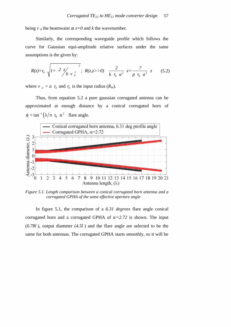
Corrugated TE11 to HE11 mode converter design 57
being ϖ0 the beamwaist at z=0 and k the wavenumber.
Similarly, the corresponding waveguide profile which follows the
curve for Gaussian equi-amplitude relative surfaces under the same
assumptions is the given by:
2
20 2 20 0 0
2 ?2 zR(z)=r 1+ ; R(z,z>>0) z= zk k r a p r aϖ
⋅⋅ ≅ ⋅ ⋅ ⋅ ⋅ ⋅ ⋅ ⋅
where 0 0 = a rϖ ⋅ and 0r is the input radius (Rin).
Thus, from equation 5.2 a pure gaussian corrugated antenna can be
approximated at enough distance by a conical corrugated horn of
( )1 20tan r−ϕ = λ π⋅ ⋅α flare angle.
Figure 5.1. Length comparison between a conical corrugated horn antenna and a
corrugated GPHA of the same effective aperture angle
In figure 5.1, the comparison of a 6.31 degrees flare angle conical
corrugated horn and a corrugated GPHA of α=2.72 is shown. The input
(0.78λ), output diameter (4.5λ) and the flare angle are selected to be the
same for both antennas. The corrugated GPHA starts smoothly, so it will be
(5.2)

Modern Corrugated Horn Antennas 58
longer for the same flare angle, but a better response in return loss and
bandwidth is expected.
5.1.1 Gaussian TE11 to HE11 mode converter performance
In order to study the behaviour of the corrugated GPHA as a TE11 to
HE11 mode converter, we will fix the input radius to 0.39λ (the most typical
value of a monomode smooth waveguide), and we will use a impedance
transformer as the one defined in chapter 3 decreasing slowly the
corrugation depth from λ/2 to λ/4 at the beginning of the mode converter.
As it will be seen in the following pictures, the behaviour of the
corrugated GPHA as TE11 to HE11 mode converter is very similar to the
behaviour of the corresponding conical corrugated horn antenna. The
smooth input part will give the designer some advantages specially in return
loss and bandwidth, as we will see later on.
Figure 5.2. a) Efficiency of corrugated GPHA to a fundamental gaussian beam
b) Efficiency of corrugated GPHA to a HE11 hybrid mode
In figure 5.2 the conversion efficiency to a fundamental gaussian beam
and to a HE11 hybrid mode are shown. It can be seen that the corrugated
GPHA in this case is a very nice TE11 to HE11 mode converter, as it was the
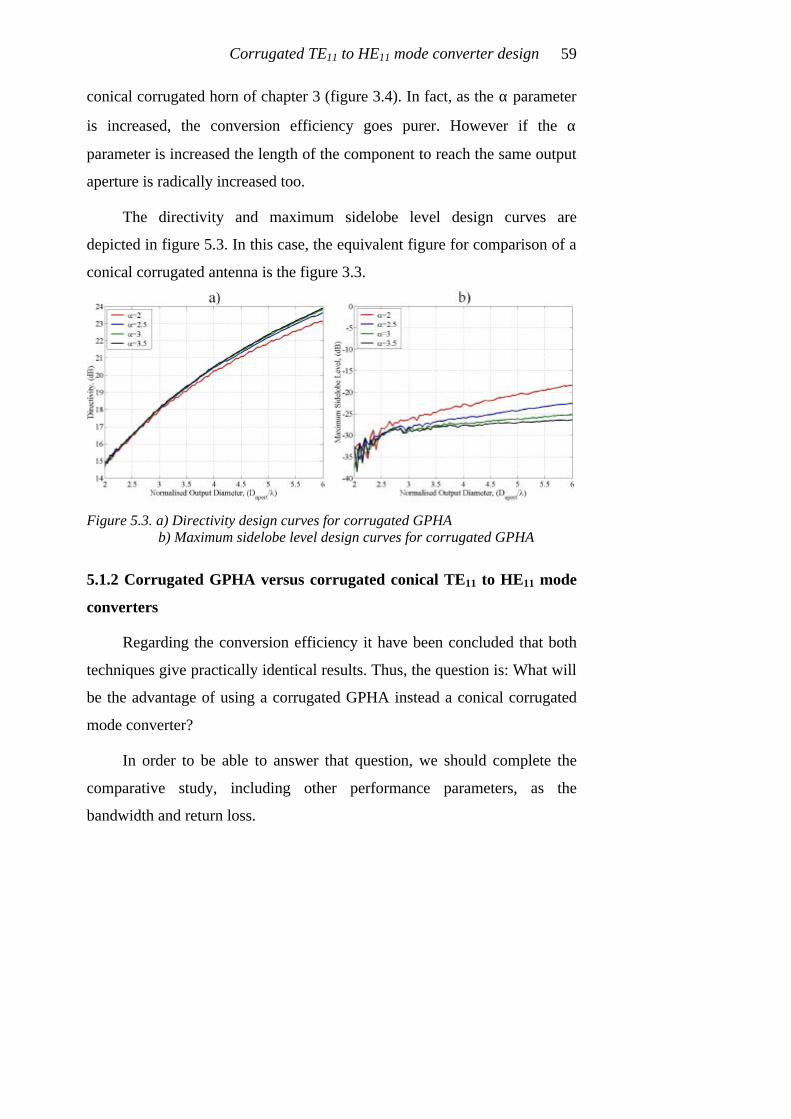
Corrugated TE11 to HE11 mode converter design 59
conical corrugated horn of chapter 3 (figure 3.4). In fact, as the α parameter
is increased, the conversion efficiency goes purer. However if the α
parameter is increased the length of the component to reach the same output
aperture is radically increased too.
The directivity and maximum sidelobe level design curves are
depicted in figure 5.3. In this case, the equivalent figure for comparison of a
conical corrugated antenna is the figure 3.3.
Figure 5.3. a) Directivity design curves for corrugated GPHA
b) Maximum sidelobe level design curves for corrugated GPHA
5.1.2 Corrugated GPHA versus corrugated conical TE11 to HE11 mode
converters
Regarding the conversion efficiency it have been concluded that both
techniques give practically identical results. Thus, the question is: What will
be the advantage of using a corrugated GPHA instead a conical corrugated
mode converter?
In order to be able to answer that question, we should complete the
comparative study, including other performance parameters, as the
bandwidth and return loss.

Modern Corrugated Horn Antennas 60
We will use two equivalent designs to compare their frequency
response: the input diameter is selected to be 0.78·λ and the output diameter
5·λ, the flare angle of the conical corrugated antenna is 5.33º which
corresponds with a α=2.96 for the corrugated GPHA.
Figure 5.4. a) Bandwidth comparison in percentage efficiency to HE11 hybrid mode
b) Bandwidth comparison in directivity
In figures 5.4 and 5.5 we can see effectively that the corrugated GPHA
TE11 to HE11 mode converter has a slightly wider bandwidth.
Figure 5.5. a) Bandwidth comparison in maximum crosspolar level b) Bandwidth comparison in maximum sidelobe level
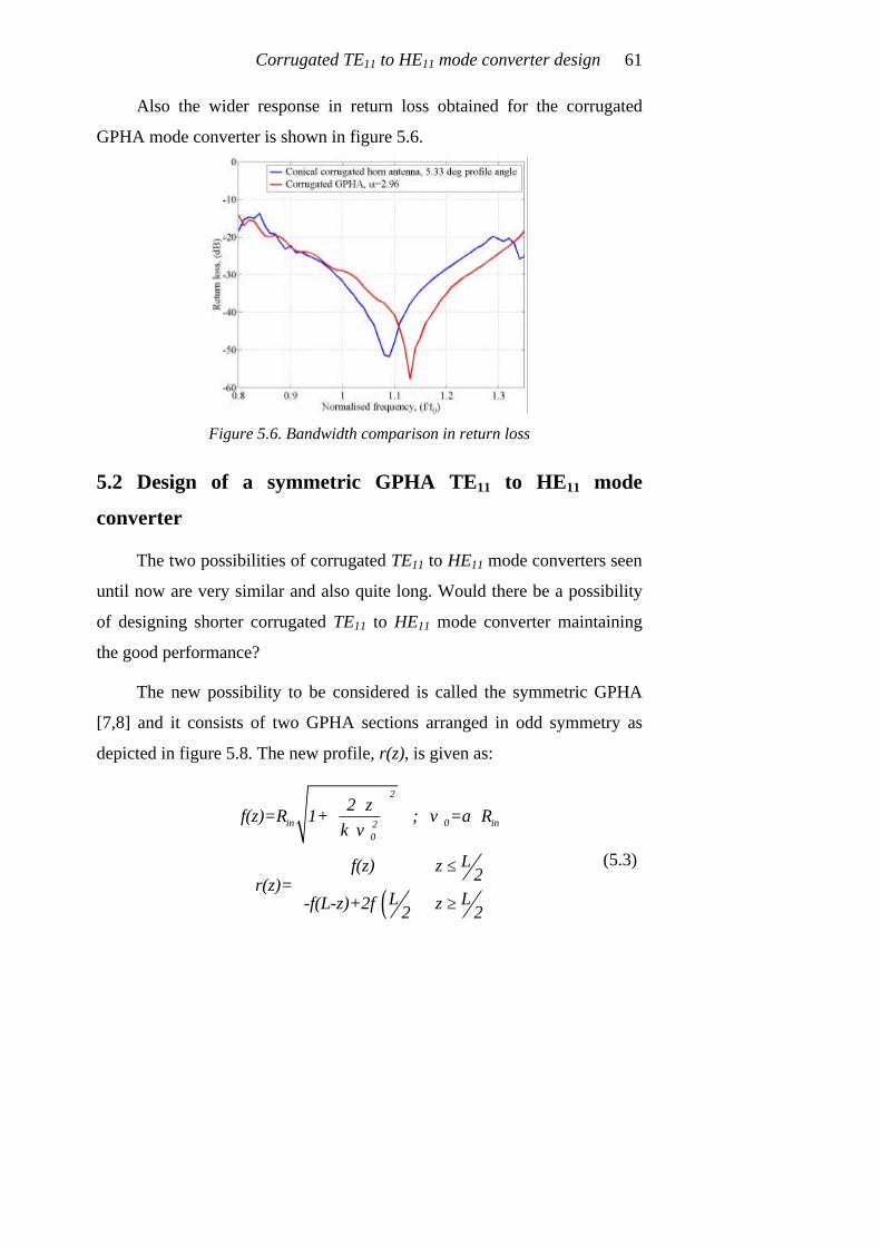
Corrugated TE11 to HE11 mode converter design 61
Also the wider response in return loss obtained for the corrugated
GPHA mode converter is shown in figure 5.6.
Figure 5.6. Bandwidth comparison in return loss
5.2 Design of a symmetric GPHA TE11 to HE11 mode
converter
The two possibilities of corrugated TE11 to HE11 mode converters seen
until now are very similar and also quite long. Would there be a possibility
of designing shorter corrugated TE11 to HE11 mode converter maintaining
the good performance?
The new possibility to be considered is called the symmetric GPHA
[7,8] and it consists of two GPHA sections arranged in odd symmetry as
depicted in figure 5.8. The new profile, r(z), is given as:
( )
2
in 0 in20
2 zf(z)=R 1+ ; =a R
k
Lf(z) z 2r(z)=L L-f(L-z)+2f z2 2
ϖϖ
⋅⋅ ⋅
≤
≥
(5.3)

Modern Corrugated Horn Antennas 62
being the L the length of the whole device, Rin the input radius, k the
wavenumber and ω0 the beamwaist.
This new component has the advantage a smooth input and output
parts and uses the gaussian propagating formula to increase quickly the
profile angle obtaining a bigger diameter in a shorter length. At the second
half part, the profile angle is reduced in order to guide the generated HE11
towards the aperture. This allows connectivity of the converter to other
components.
At the throat, this component also includes an impedance transformer
decreasing linearly from λ/2 to λ/4 the corrugation depth as any corrugated
horn antenna with a smooth waveguide at the input port.
Figure 5.7. Symmetrical corrugated GPHA TE11 to HE11 mode converter

Corrugated TE11 to HE11 mode converter design 63
5.2.1 Symmetrical corrugated GPHA TE11 to HE11 mode converter
performance
Assuming the same input diameter of 0.78·λ, the conversion efficiency
to an HE11 mode and a fundamental Gaussian mode are depicted in figure
5.8.
Figure 5.8. a) Efficiency of symmetrical corrugated GPHA to a fundamental
gaussian beam b) Efficiency of symmetrical corrugated GPHA to a HE11 hybrid mode
In figure 5.8, the high conversion efficiency of this new symmetrical
corrugated GPHA converter is proved. Differently to the direct corrugated
GPHA converter, this one doesn’t present better efficiency as bigger is α
parameter, in fact the best efficiency could be approximated by (empirical
formula):
0a=0.28 D +0.5⋅
where 0 apertD D λ= is the normalised output aperture diameter of the
component in wavelengths. This optimal α parameter has been depicted as a
yellow line in figures 5.8, 5.9 and 5.10.
(5.4)
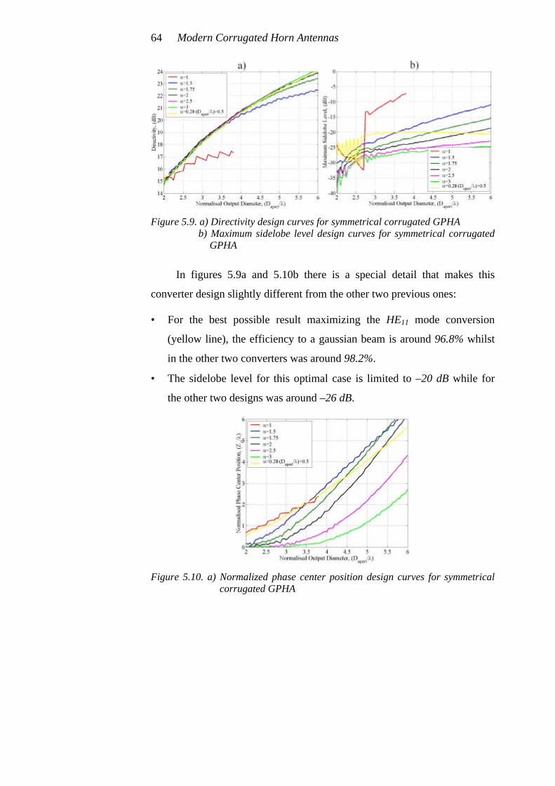
Modern Corrugated Horn Antennas 64
Figure 5.9. a) Directivity design curves for symmetrical corrugated GPHA
b) Maximum sidelobe level design curves for symmetrical corrugated GPHA
In figures 5.9a and 5.10b there is a special detail that makes this
converter design slightly different from the other two previous ones:
• For the best possible result maximizing the HE11 mode conversion
(yellow line), the efficiency to a gaussian beam is around 96.8% whilst
in the other two converters was around 98.2%.
• The sidelobe level for this optimal case is limited to –20 dB while for
the other two designs was around –26 dB.
Figure 5.10. a) Normalized phase center position design curves for symmetrical
corrugated GPHA

Corrugated TE11 to HE11 mode converter design 65
Usually, because of these limitations observed, we shall not use these
symmetric GPHA as radiating antennas but as the initial part of a composed
horn antenna that includes a pure GPHA section at its end. This type of
compositions will be more extensively covered in following chapters.
Nevertheless, the symmetric GPHA is always a possibility to be
consider if our design requirements enable us to use them, obtaining
considerably short antennas.
5.3 Designing a Corrugated TE11 to HE11 mode converter
The optimum value of the α parameter has been obtained for the case
of symmetric GPHA TE11-HE11 mode converter to define the most pure
HE11 mode (equation 5.4).
Similarly, we propose two new and empirical formulas to define the
parameters of a conical (flare angle) and direct corrugated GPHA (α
parameter) TE11-HE11 mode converters to obtain the higher conversion
efficiency to HE11 mode with the shorter length. The formulas have been
extracted with the aid of figures 3.4b and 5.2b, and all of them are a function
of the normalized output diameter 0D .
For a conical corrugated TE11 to HE11 mode converter, the obtained
formula can be written as follows:
1.6
0
70Profile angle degrees
Dϕ= =
For a direct corrugated GPHA TE11 to HE11 mode converter the design
equation will be:
1.6
0
2.57Dα
π= ⋅
(5.5)
(5.6)

Modern Corrugated Horn Antennas 66
Equation 5.6 could be obtained from equation 5.5 selecting exactly the
same profile angle as in the conical corrugated converter for the end of the
component as it was explained in equation 5.2.
Then, with the use of equations 5.4, 5.5 and 5.6, we could define the
best mode converter for a given output diameter.
In figure 5.11 the efficiencies to a fundamental gaussian beam and to a
HE11 mode of each converter are shown. All the converters give conversion
efficiencies to an HE11 hybrid mode above 99.9%, for normalized aperture
diameters higher than 4. In fact, the efficiency for the three models is nearly
the same. Nevertheless, the efficiency to a fundamental gaussian beam is
higher in the conical and GPHA models due to the higher sidelobe of the
symmetrical GPHA one, (see figure 5.12b).
Figure 5.11. a) Efficiency of optimal TE11 to HE11 corrugated mode converters to a
fundamental gaussian beam b) Efficiency of optimal TE11 to HE11 corrugated mode converters to a
HE11 hybrid mode
In figure 5.12a, it could be noticed that the symmetrical GPHA model
has a slightly higher directivity for the same output aperture.

Corrugated TE11 to HE11 mode converter design 67
Figure 5.12. a) Directivity design curves for optimal TE11 to HE11 corrugated mode converters
b) Maximum sidelobe level design curves for optimal TE11 to HE11 corrugated mode converters
A comparison of the length in the three models is shown in figure
5.13a. From the figures, we can conclude that the symmetrical corrugated
GPHA converter will usually be the best choice, except for low aperture
diameters, ( 0 3D ≤ ), where the conical or direct GPHA give better
efficiency solutions (see figure 5.11b) in a similar length.
From figure 5.13c, we can see that for large aperture diameters, the
length of the symmetrical GPHA can be half of the other two models, so the
length improvement is very high.
The mode content of the conical and GPHA corrugated TE11 to HE11
mode converters are really similar (figure 5.13b) because the mode mixture
at the aperture is practically the same, (83.3% of TE11, 14.9% of TM11, 0.9%
of TE12 and 0.7% of TM12). However, for the symmetrical corrugated
GPHA the mode content is slightly different, (82.2% of TE11, 12.7% of
TM11, 3.2% of TE12 and 1.5% of TM12). This could be probably the reason

Modern Corrugated Horn Antennas 68
of the different radiation behaviour of the symmetric GPHA in relation with
the other two mode converters.
Figure 5.13. a) Length comparison for optimal TE11 to HE11 corrugated mode
converters b) Percentage of TE1n and TM1n mode content for optimal TE11 to
HE11 corrugated mode converters c) Length comparison for optimal TE11 to HE11 corrugated mode
converters of Dapert/λ=5
In relation with the bandwidth, the performance are quite similar
between the three different techniques, improving with the Gaussian profiles
(symmetric and non symmetric) the bandwidth and the return loss due to the
smoothed initial part of the horn.

Corrugated TE11 to HE11 mode converter design 69
5.4 Corrugated TE11 to HE11 mode converter bandwidth
comparison
To make a complete mode converter comparison between the three
different models we have been explaining, it is necessary to inspect on the
bandwidth of each mode converter.
For all the three designs, a normalized output diameter of 0D =5 has
been used. For this 0D , the conical corrugated mode converter presents a
profile angle of 5.33 degrees, the direct GPHA mode converter presents an
α=2.96 and the symmetrical GPHA an α=1.9.
Figure 5.14 a) Bandwidth comparison in percentage efficiency to the HE11 hybrid
mode b) Bandwidth comparison in directivity
Figure 5.14a shows that the efficiency to the HE11 mode of the
symmetrical GPHA converter is not as nice as the other two components in
all the bandwidth (25% bandwidth with an efficiency above 99.8%). The
direct GPHA presents the best bandwidth efficiency, (47% bandwidth with
an efficiency above 99.8%). Conical corrugated converter presents also a
wide bandwidth efficiency to HE11 (41% bandwidth whit an efficiency
above 99.8%).

Modern Corrugated Horn Antennas 70
If we have a look to figure 5.14b where the directivity of each design
is plotted. The narrower bandwidth happens for the conical corrugated
converter. The main difference in that figure is that the symmetrical
converter presents at lower frequencies of the band a higher directivity than
the other two.
Figure 5.15. a) Bandwidth comparison in maximum crosspolar level
b) Bandwidth comparison in maximum sidelobe level
Figure 5.15a shows the bandwidth comparison in crosspolar level (λ/4
corrugation depth). The three converter models present a similar bandwidth
response at lower frequencies of the band. At higher frequencies, the direct
GPHA shows a slightly better crosspolar bandwidth followed by the
symmetrical GPHA. The sidelobe level can be checked in figure 5.15b. As it
was assumed, the symmetrical GPHA has a 5 dB higher sidelobe level
response. The direct GPHA has a wider bandwidth response in sidelobe
level.
Regarding return loss, figure 5.16, symmetrical GPHA and direct
GPHA show a wider bandwidth at the lower part of the frequency band
(smoother throat in those two converters), whereas at higher frequencies of
the band the conical corrugated mode converter performs better results.
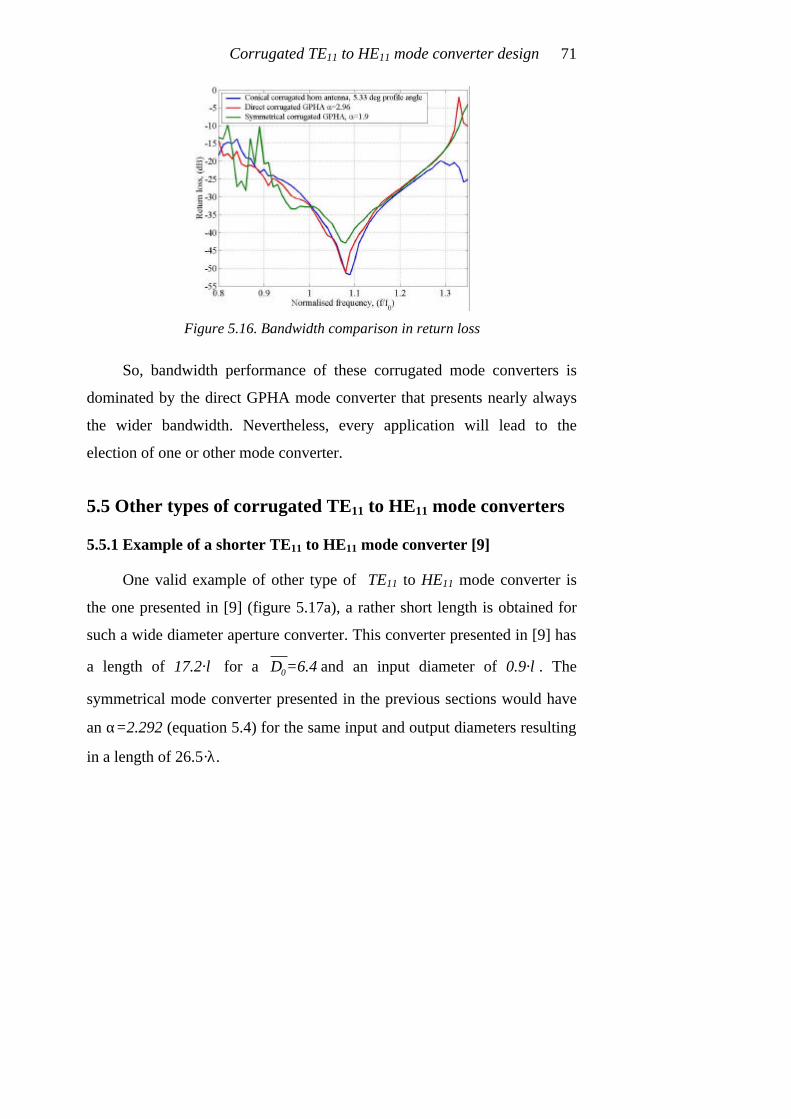
Corrugated TE11 to HE11 mode converter design 71
Figure 5.16. Bandwidth comparison in return loss
So, bandwidth performance of these corrugated mode converters is
dominated by the direct GPHA mode converter that presents nearly always
the wider bandwidth. Nevertheless, every application will lead to the
election of one or other mode converter.
5.5 Other types of corrugated TE11 to HE11 mode converters
5.5.1 Example of a shorter TE11 to HE11 mode converter [9]
One valid example of other type of TE11 to HE11 mode converter is
the one presented in [9] (figure 5.17a), a rather short length is obtained for
such a wide diameter aperture converter. This converter presented in [9] has
a length of 17.2·λ for a 0D =6.4 and an input diameter of 0.9·λ. The
symmetrical mode converter presented in the previous sections would have
an α=2.292 (equation 5.4) for the same input and output diameters resulting
in a length of 26.5·λ.

Modern Corrugated Horn Antennas 72
This new converter [9] works very nice but for a narrower bandwidth
(see figure 5.17b). Sometimes a solution like this one could be perfect for
several applications.
Figure 5.17. a) CSIRO TE11 to HE11 corrugated mode converter with aperture
diameter of 6.4·λ b) Return loss, maximum crosspolar level, -directivity and maximum
sidelobe level with the usable bandwidth of this mode converter
In this mode converter, the efficiency to an HE11 mode is not a nice as
in the other converters (around 98.5%) seen in this chapter (see figure 5.18),

Corrugated TE11 to HE11 mode converter design 73
but as we will see in the next chapter, it can be enough for certain
applications.
Figure 5.18. Percent efficiency in band to HE11 mode of CSIRO converter
5.5.2 Choked TE11 to HE11 mode converter
Another and very promising TE11 to HE11 mode converter is the
choked waveguide mode converter.
Figure 5.19. a) Choked waveguide TE11 to HE11 corrugated mode converter,
Dapert=2.6·λ b) Return loss, maximum crosspolar level, -directivity and maximum
sidelobe level with the usable bandwidth of this mode converter

Modern Corrugated Horn Antennas 74
In this case the corrugations are parallel to the electromagnetic waves
propagation direction (see figure 5.19a). Really very short devices can be
obtained with this technique (see figure 5.19a a TE11 to HE11 mode
converter with 2.6·λ aperture diameter and 2·λ long and 0.78·λ input
diameter). The corresponding symmetrical mode converter would present an
α=1.228 by means of equation 5.4 with 0D =2.6 and a corresponding length
of 2.85·λ.
This compact mode converter has another very nice advantage: it
reduces a lot the manufacture process because it doesn’t present deep
corrugations at the throat as the other corrugated profiles. Usually, these
deep λ/2 corrugations complicate a lot the manufacture for a milling
machine.
Figure 5.20. Percent efficiency in band to HE11 mode of choked converter
The disadvantage of this mode converter is its bandwidth (see figure
5.19b), around 10-15%. Nevertheless it could be enough for many
applications. Also, in this mode converter, the efficiency to an HE11 mode is

Corrugated TE11 to HE11 mode converter design 75
not very nice (see figure 5.20) as in the converters presented in this chapter
(around 98%) but we will see in the next chapter that this one can be really
good for several applications.
5.6 Conclusions
The TE11 to HE11 mode converter state of the art technology has been
explained. Several empirical formulas have been defined to aid in the design
of the different converters.
If the converter has vertical corrugations, the design will always have
approximately the following properties:
• The input diameter corresponds to a monomode smooth waveguide.
• An impedance transformer of enough length that changes linearly the
corrugation depth between λ/2 to λ/4 must be included at the throat.
• A controlled aperture angle, collecting smoothly the inside fields
towards the output aperture.
• As smooth is the taper change of the converter as wide will be the usable
bandwidth. Converters of very short length and sharp changes are used
for narrow bandwidth requirements only.
Every application can determine the use of one or other design
technique.
The use of the choked waveguide converter can reduce really a lot the
length if the application has not much bandwidth, and this converter is also
very easy to manufacture because of the lack of the λ/2 to λ/4 tapered
corrugation depth change at the throat.

Modern Corrugated Horn Antennas 76
5.7 References
[1] Potter, P. D., “A New Horn Antenna with Suppressed Sidelobes and
Equal Beamwidths”, Microwave Journal, vol. VI, June 1963, pp. 71-78.
[2] Christophe Granet and Val Dyadyuk, “Compact Potter-Type Horns for a
Traffic Management Radar”, AP2000 Millennium Conference on
Antennas & Propagation, 9-14 April 2000, Davos, Switzerland
[3] Gonzalo R., Del Río C. and Sorolla M., “Generation of the HE11 Mode
from Monomode Smooth Circular Waveguide”, Proc. 21st.
International Conference on Infrared and Millimeter Waves, BTh8,
Berlin, July 1996.
[4] Gonzalo, R., Teniente, J. and Del Río, C., “Very Short and Efficient
Feeder Design from Monomode Waveguide”, 1997 IEEE AP-S
International Symposium and URSI Radio Science Meeting, 14-18 of
July, Montreal, Canada.
[5] Gonzalo, R., Teniente, J. and del Río, C., “Improved Radiation Pattern
Performance of Gaussian Profiled Horn Antennas”, IEEE Transactions
on Antennas and Propagation, Vol. 50, N. 11, pp. 1505-1513,
November 2002.
[6] S.G. Hay, S.J. Barker, C. Granet, A.R. Forsyth, T.S. Bird, M.A. Sprey
and K.J. Greene, “Multibeam Earth Station Antenna for a European
Teleport Application”, 2001 IEEE AP-S International Symposium and
URSI Radio Science Meeting, 8-13 of July, Boston, Massachusetts,
United States
[7] Gonzalo R., Del Río C. and Sorolla M., “Generation of the HE11 Mode
from Monomode Smooth Circular Waveguide”, Proc. 21st.

Corrugated TE11 to HE11 mode converter design 77
International Conference on Infrared and Millimeter Waves, BTh8,
Berlin, Germany, July 1996.
[8] Spanish Patent P.9601636, “Mode converter: from the TE11 monomode
circular waveguide mode to the HE11 corrugated circular waveguide
mode”, Authors: Carlos Del Río, Ramón Gonzalo, y Mario Sorolla,
11/07/1996.
[9] S.G. Hay, S.J. Barker, C. Granet, A.R. Forsyth, T.S. Bird, M.A. Sprey
and K.J. Greene, “Multibeam Earth Station Antenna for a European
Teleport Application” 2001 IEEE AP-S International Symposium and
URSI Radio Science Meeting, 8-13 of July, Boston, United States.

Modern Corrugated Horn Antennas 78
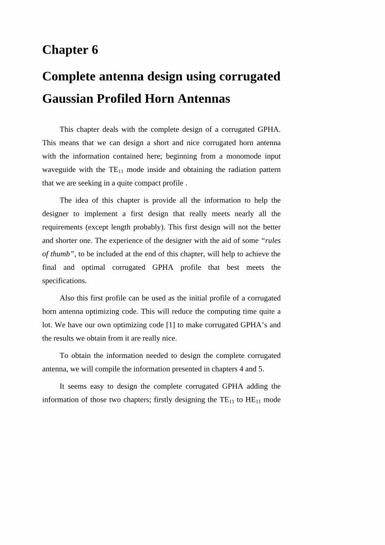
Chapter 6
Complete antenna design using corrugated
Gaussian Profiled Horn Antennas
This chapter deals with the complete design of a corrugated GPHA.
This means that we can design a short and nice corrugated horn antenna
with the information contained here; beginning from a monomode input
waveguide with the TE11 mode inside and obtaining the radiation pattern
that we are seeking in a quite compact profile .
The idea of this chapter is provide all the information to help the
designer to implement a first design that really meets nearly all the
requirements (except length probably). This first design will not the better
and shorter one. The experience of the designer with the aid of some “rules
of thumb”, to be included at the end of this chapter, will help to achieve the
final and optimal corrugated GPHA profile that best meets the
specifications.
Also this first profile can be used as the initial profile of a corrugated
horn antenna optimizing code. This will reduce the computing time quite a
lot. We have our own optimizing code [1] to make corrugated GPHA’s and
the results we obtain from it are really nice.
To obtain the information needed to design the complete corrugated
antenna, we will compile the information presented in chapters 4 and 5.
It seems easy to design the complete corrugated GPHA adding the
information of those two chapters; firstly designing the TE11 to HE11 mode

Modern Corrugated Horn Antennas 80
converter with the information of chapter 5 and then adding the corrugated
GPHA with the information of chapter 4. By means of stacking those two
parts together we would have the complete design; but this chapter will
reveal that it is not as easy as seems to be. In fact, the interaction of both
parts will change the performance of both. A complete study of the
components stacked together will be done in this chapter.
6.1 Complete design of a corrugated GPHA with a conical
corrugated input as TE11 to HE11 mode converter
To design a complete corrugated antenna with a conical corrugated
input section finishing with a corrugated GPHA; we must know first which
is the directivity at the central frequency for the design that we need. If the
requirement is given in terms of beamwidth a quick view of appendix III
will directly change this parameter to directivity.
After knowing the directivity, we should select approximately the D0
or inner diameter ( 0 0D D λ= where D0 is the output diameter of the
corrugated conical TE11 to HE11 mode converter and the input diameter of
the corrugated GPHA section). To select this diameter, we could ideally
have a look at figure 4.8. But this figure is the first one that changes due to
the interaction of the two components stacked together.
In fact, what happens is that the directivity obtained for a given
normalised inner diameter, is approximately around 1 dB higher that the
directivity curves from figure 4.8.
At this point, we should consider the complete set of mode converter
and gaussian section together (figure 6.1) for directivity instead of figure
4.8; assuming that the conical corrugated converter flare angle has been
Complete antenna design using corrugated GPHA’s 81
selected by means of equation 5.5 ( ( )1.6
070 Dϕ = degrees), the input
diameter is around 0.78·λ and trying with different lengths for the final
section (f := 0.05 to 0.3).
Figure 6.1 Directivity design curves for the combination conical+GPHA
From chapter 4 we select the length in terms of the parameter defined
in equation 4.3, length factor, (f ), according to the maximum allowable
sidelobe level for our design, (figure 4.6b). Unfortunately, also this
parameter changes for the complete design and we should instead make use
of figure 6.2b to select the appropriate value of f. The required length for the
second corrugated GPHA section will be longer than the one assumed in
chapter 4 for the same sidelobe level.
Also from chapter 4, we knew that α parameter of the corrugated
GPHA section was fixed at α=0.59 for a better efficiency of the radiated
field to a fundamental gaussian beam. However, α parameter for the

Modern Corrugated Horn Antennas 82
complete corrugated antenna must change and it depends on both, the
normalized inner diameter, ( 0D ), and the length factor, (f).
Figure 6.2 a) Efficiency to a fundamental gaussian beam for the combination
conical+GPHA b) Maximum sidelobe level for the combination conical+GPHA
Complete antenna design using corrugated GPHA’s 83
Optimum α parameter is below 0.59 for short corrugated GPHA
sections and/or small inner diameters and above 0.59 for long corrugated
GPHA sections and/or large inner diameters. A rather complex empirical
formula to select the optimum α parameter is given in equation 6.1.
0.18
01.6 2
100 2 4f f f
Dα− ⋅ = ⋅ + −
where 0D is the normalised inner diameter of the corrugated GPHA
section and f is the length factor.
To finish the combination conical+GPHA design we should select the
corrugation values, and this is the easiest part. As defined in chapters 3 to 5,
corrugation period (p) should be around λ/5, corrugation tooth width (w)
around p/2 or thinner, corrugation depth around λ/4, first corrugation depth
around λ/2 tapered to λ/4 with an impedance transformer of a length
approximately equal to the distance from the throat of the corrugated horn
antenna to where the antenna profile reaches an inner diameter where the
TM11 mode is in propagation.
With the information considered until this point we have enough to
fully design the antenna we desire.
As summary, in figure 6.3a, the normalised antenna length against
directivity is depicted; this figure shows that as longer we make the second
section of the antenna (increasing f, the length factor) as shorter the
complete profile will be. Additionally, the sidelobe level will decrease
increasing f, this means that a shorter combination conical+GPHA gives a
better radiation pattern, (see figure 6.2b). The disadvantage is that a longer
second section corrugated GPHA means a wider output diameter of the
(6.1)

Modern Corrugated Horn Antennas 84
complete antenna (see figure 6.3b) and a compromise between length and
output diameter for a given directivity must be reached.
Figure 6.3 a) Normalised antenna length against directivity for the combination
conical+GPHA b) Normalised antenna output diameter against directivity for the
combination conical+GPHA (conical corrugated horn antenna output diameter is also depicted for a better comparison)
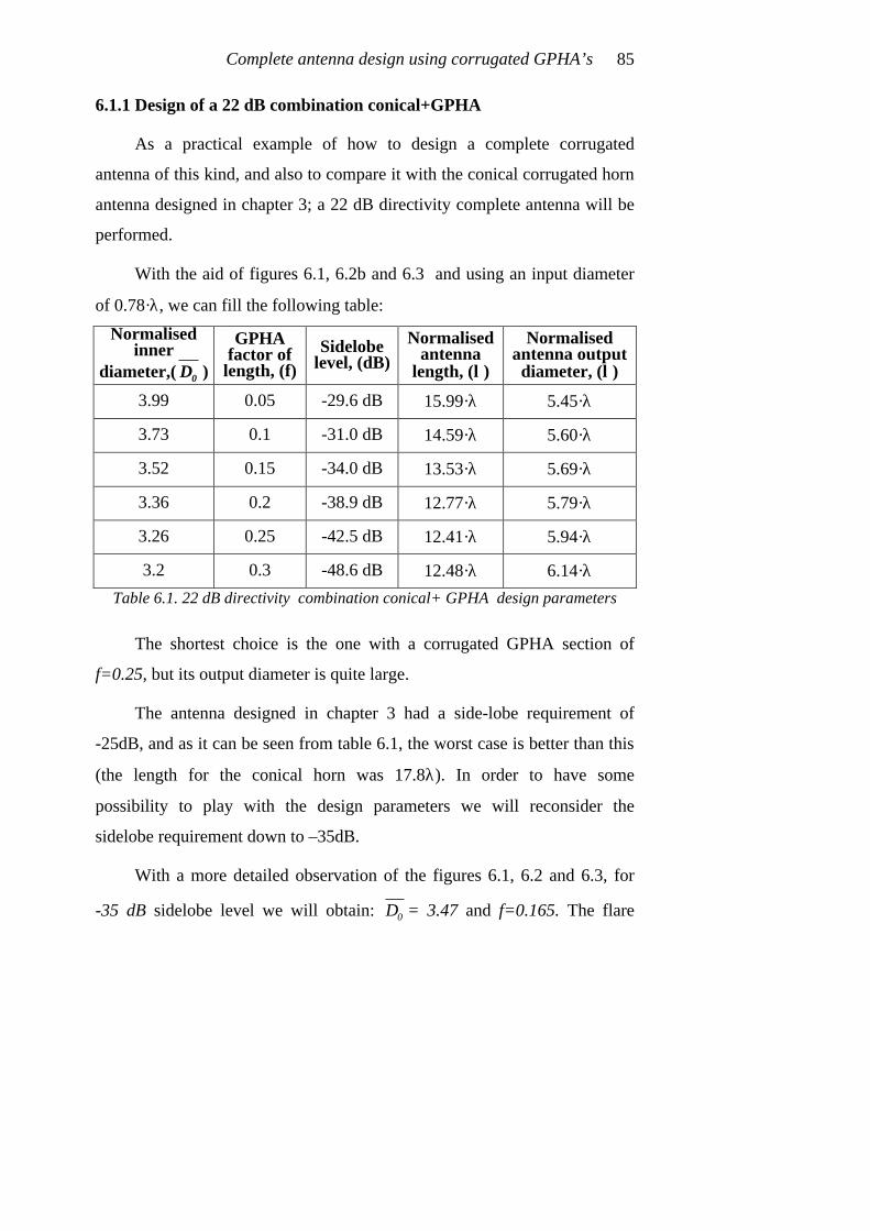
Complete antenna design using corrugated GPHA’s 85
6.1.1 Design of a 22 dB combination conical+GPHA
As a practical example of how to design a complete corrugated
antenna of this kind, and also to compare it with the conical corrugated horn
antenna designed in chapter 3; a 22 dB directivity complete antenna will be
performed.
With the aid of figures 6.1, 6.2b and 6.3 and using an input diameter
of 0.78·λ, we can fill the following table:
Normalised inner
diameter,( 0D )
GPHA factor of
length, (f) Sidelobe
level, (dB) Normalised
antenna length, (λ)
Normalised antenna output diameter, (λ)
3.99 0.05 -29.6 dB 15.99·λ 5.45·λ
3.73 0.1 -31.0 dB 14.59·λ 5.60·λ
3.52 0.15 -34.0 dB 13.53·λ 5.69·λ
3.36 0.2 -38.9 dB 12.77·λ 5.79·λ
3.26 0.25 -42.5 dB 12.41·λ 5.94·λ
3.2 0.3 -48.6 dB 12.48·λ 6.14·λ
Table 6.1. 22 dB directivity combination conical+ GPHA design parameters
The shortest choice is the one with a corrugated GPHA section of
f=0.25, but its output diameter is quite large.
The antenna designed in chapter 3 had a side-lobe requirement of
-25dB, and as it can be seen from table 6.1, the worst case is better than this
(the length for the conical horn was 17.8λ). In order to have some
possibility to play with the design parameters we will reconsider the
sidelobe requirement down to –35dB.
With a more detailed observation of the figures 6.1, 6.2 and 6.3, for
-35 dB sidelobe level we will obtain: 0D = 3.47 and f=0.165. The flare

Modern Corrugated Horn Antennas 86
angle for the conical corrugated mode converter (equation 5.5) will be of 1.670 3.47 =9.56 degrees. Then, the conical corrugated converter will result
in a length of 8·λ, with an input diameter at the throat of 0.78·λ. The
corrugated GPHA part will result in a length of
( )23.47 0.165 1+3.47 =5.1 ?λ ⋅ ⋅ ⋅ ⋅ (equation 4.3), and with an α=0.641
(equation 6.1).
The corrugation parameters we are going to use for this antenna design
will be: corrugation period (p=λ/5), corrugation tooth width (w=p/3),
corrugation depth (d=λ/4), first corrugation depth λ/2 linearly tapered to λ/4
in a length of 1.3·λ.
The total length of this antenna will be of 13.27·λ taking into account
the fact that corrugations provide discrete lengths and each section length is
defined by an integer number of corrugation periods. The formula for the
length of a complete corrugated antenna of two sections will be:
section 1 section 2Total length=ceil(L /p) p+ceil(L /p) p+w⋅ ⋅ where the operator ceil(x) rounds x to the nearest integer towards infinity.
Lsection 1 and Lsection 2 are the calculated lengths of the two sections and p, w
are the corrugation period and corrugation tooth width respectively.
In figure 6.4 the resultant antenna is depicted as well as its resultant far
field radiation pattern.
This antenna design is 4.5·λ shorter than the conical corrugated design
of chapter 3 and presents 10 dB lower sidelobe level. On the other hand its
output diameter is 0.86·λ wider.
(6.2)

Complete antenna design using corrugated GPHA’s 87
Figure 6.4. Combination of corrugated GPHA with a conical corrugated mode
converter input for 22 dB directivity and –35 dB sidelobe level
The reason why GPHA’s present wider output diameters for the same
directivity is strongly related with the position of its phase centre, in fact as
it can be seen in figure 6.4, the phase centre for the combination conical +
GPHA design is placed at 3.59·λ from the aperture (27% of the total antenna
length, in this example), compared to the conical corrugated horn antenna
design of figure 3.10 where the phase centre was only a 14% inside of the
horn (see figure 3.10).
A phase centre placed far away from the aperture of the horn antenna
gives less directivity for a given output diameter (disadvantage) but also
gives more stability in the phase centre position along a wider frequency
band (advantage).

Modern Corrugated Horn Antennas 88
An optimisation of this example of a combination conical + GPHA is
still possible, and a reduction in length of at least 10% should be quite easy
to obtain. A method that usually works to optimise the length is to shorten
the input converter an lengthen the corrugated GPHA section increasing a
little the α value to reduce the output diameter.
6.2 Complete design of a corrugated GPHA with a
corrugated GPHA input as TE11 to HE11 mode converter
The design of a combination of a corrugated GPHA with another
corrugated GPHA at its input that serves as TE11 to HE11 mode converter is
not needed to be covered specifically. The results will be just the same as
the ones described with conical corrugated mode converter but with a bit
longer profile and better bandwidth specially regarding return loss. The
formula to be used to design the first section corrugated GPHA mode
converter will be the given in equation 5.6, (1.6
0a=2.57 p D⋅ ).
Figure 6.5 Normalised antenna length against directivity for the combination
GPHA + GPHA

Complete antenna design using corrugated GPHA’s 89
Figures 6.1, 6.2 and 6.3b can be used directly for the design, the only
difference will be that the figure 6.3a (complete antenna length) is directly
substituted by figure 6.5.
6.3 Complete design of a corrugated GPHA with a
symmetrical corrugated GPHA input as TE11 to HE11 mode
converter
To design a combination of a corrugated GPHA with another
symmetrical GPHA at the input, is really similar to the last described
designs. The only difference is that the formula selected to define optimum
α parameter given in chapter 5, (equation 5.4), doesn’t work optimally with
this complete design.
The reason is that the symmetrical corrugated GPHA TE11 to HE11
mode converter presented a sidelobe level around –20 dB for that empirical
formula. In fact, we obtained the equation 5.4 to achieve the highest
possible efficiency to the HE11 mode at its aperture and not the lowest
sidelobe level.
Then, another formula for the α parameter for the symmetrical
corrugated GPHA with lower sidelobe level should be specified.
After a deep and careful study of figure 5.9b, and consider several
possibilities, we have found the optimum formula for the symmetrical
corrugated GPHA that gives a nice compromise between length and
performance of the complete antenna. This formula is expressed in equation
6.3 and achieves a sidelobe level in the symmetrical corrugated GPHA
converter of approximately –23 to -24 dB, (see figure 6.6), instead of the
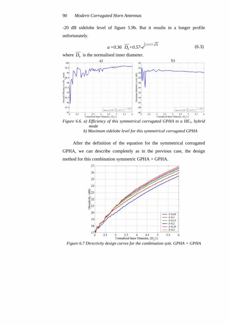
Modern Corrugated Horn Antennas 90
-20 dB sidelobe level of figure 5.9b. But it results in a longer profile
unfortunately.
( )0
02.2-2.5 D=0.36 D +0.57-eα
⋅⋅
where 0D is the normalised inner diameter.
Figure 6.6. a) Efficiency of this symmetrical corrugated GPHA to a HE11 hybrid
mode b) Maximum sidelobe level for this symmetrical corrugated GPHA
After the definition of the equation for the symmetrical corrugated
GPHA, we can describe completely as in the previous case, the design
method for this combination symmetric GPHA + GPHA.
Figure 6.7 Directivity design curves for the combination sym. GPHA + GPHA
(6.3)

Complete antenna design using corrugated GPHA’s 91
To start the design, we need to select from figure 6.7 the needed
directivity of our design which will give a value for 0D .
Figure 6.8 a) Efficiency to a fundamental gaussian beam for the combination
symmetrical GPHA + GPHA b) Maximum sidelobe level for the combination symmetrical GPHA +
GPHA
The value of 0D is affected by the sidelobe level we want to achieve
in the design. Then we must consider figure 6.8b in order to select exactly

Modern Corrugated Horn Antennas 92
the length of the second section corrugated GPHA for the desired side-lobe
level. Figure 6.9 can help us to select the most compact profile that fulfils
all of our requirements. The design procedure is exactly the same as in the
last two sections, but with the use of new figures.
Figure 6.9 a) Normalised antenna length against directivity for the combination
Symmetrical GPHA + GPHA b) Normalised antenna output diameter against directivity for the
combination symmetrical GPHA + GPHA (conical corrugated horn antenna output diameter is also depicted for a better comparison)

Complete antenna design using corrugated GPHA’s 93
6.3.1 Design of a 22 dB combination symmetrical GPHA + GPHA
Again, as a practical example of how to design a complete corrugated
antenna, and also to compare it with the conical corrugated horn antenna
designed in chapter 3; we are going to design a 22 dB directivity
combination of a GPHA output section with a symmetrical corrugated
GPHA mode converter as input.
With the aid of figures 6.7, 6.8b and 6.9 and using an input diameter
of 0.78·λ, we can summarize the following table:
Normalised inner
diameter,( 0D )
GPHA factor of
length, (f) Sidelobe
level, (dB) Normalised
antenna length, (λ)
Normalised antenna output diameter, (λ)
3.94 0.05 -28.2 dB 13.85·λ 5.39·λ
3.65 0.1 -31.1 dB 12.93·λ 5.50·λ
3.48 0.15 -35.6 dB 12.48·λ 5.64·λ
3.41 0.2 -41.6 dB 12.53·λ 5.86·λ
3.37 0.25 -43.5 dB 13.07·λ 6.12·λ
3.37 0.3 -54.9 dB 13.57·λ 6.43·λ
Table 6.2. 22 dB directivity combination symmetrical GPHA + GPHA design parameters (symmetrical corrugated GPHA input converter)
With the information of table 6.2 we should decide what design to do.
Again, to compare it with the antenna designed in chapter 3 and with the
antenna designed in the first section of this chapter, we have decided to fix
the maximum sidelobe level to –35 dB.
In this case, we can extract from the table the following parameters for
the design: 0D = 3.48 and f=0.15. The α parameter (equation 6.3) for the
symmetrical corrugated GPHA converter input should be
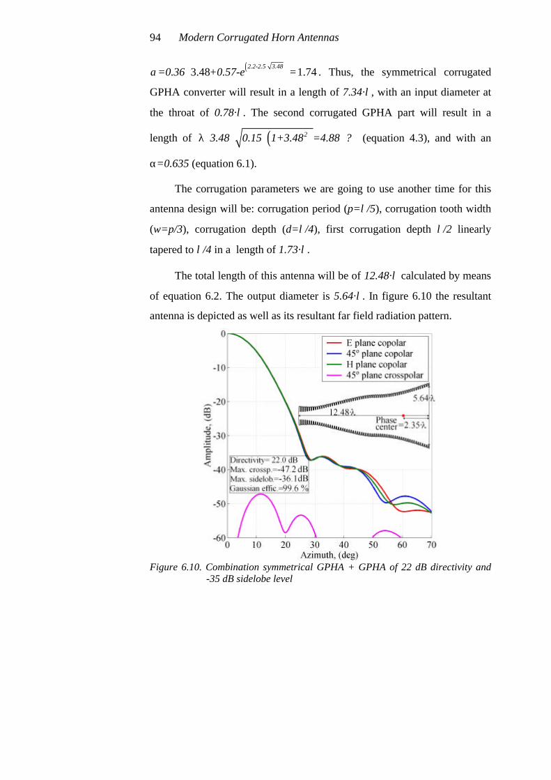
Modern Corrugated Horn Antennas 94
( )3.48 1.742.2-2.5 3.48
=0.36 +0.57-eα⋅
⋅ = . Thus, the symmetrical corrugated
GPHA converter will result in a length of 7.34·λ, with an input diameter at
the throat of 0.78·λ. The second corrugated GPHA part will result in a
length of ( )23.48 0.15 1+3.48 =4.88 ?λ ⋅ ⋅ ⋅ ⋅ (equation 4.3), and with an
α=0.635 (equation 6.1).
The corrugation parameters we are going to use another time for this
antenna design will be: corrugation period (p=λ/5), corrugation tooth width
(w=p/3), corrugation depth (d=λ/4), first corrugation depth λ/2 linearly
tapered to λ/4 in a length of 1.73·λ.
The total length of this antenna will be of 12.48·λ calculated by means
of equation 6.2. The output diameter is 5.64·λ. In figure 6.10 the resultant
antenna is depicted as well as its resultant far field radiation pattern.
Figure 6.10. Combination symmetrical GPHA + GPHA of 22 dB directivity and
-35 dB sidelobe level

Complete antenna design using corrugated GPHA’s 95
This antenna design is 5.3·λ shorter than the conical corrugated design
of chapter 3 and presents 10 dB lower sidelobe level but its output diameter
is 0.78·λ wider. It is also 0.8·λ shorter than the one with conical corrugated
converter input and presents a 0.08·λ narrower output diameter.
The phase centre for this combination symmetrical GPHA + GPHA
design is also placed inside the horn antenna 2.35·λ (a 19% inside from the
output aperture, in this example). So it is not as inside the horn antenna as in
the corrugated GPHA with conical corrugated input converter (27% inside).
6.4 Comparison between different combinations
Once we know how to design a corrugated GPHA we need to know
which method to select depending upon our requirements. In fact, what we
would pursue is to design the most compact antenna profile that meets all of
our requirements.
In the following pages, figures 6.11, 6.12 and 6.13 will help for sure a
lot to select the optimum design. All the figures are based in the formulas
described before in the chapter and depend on the length of the second
section corrugated GPHA.
Usually, the most compact profile will be the combination
symmetrical GPHA + GPHA, but in some cases, another input profiles must
be chosen. Length, output diameter, sidelobe level and bandwidth (will be
covered more extensively in the following sections), will be the
requirements to achieve and will lead to the prefect design for sure.
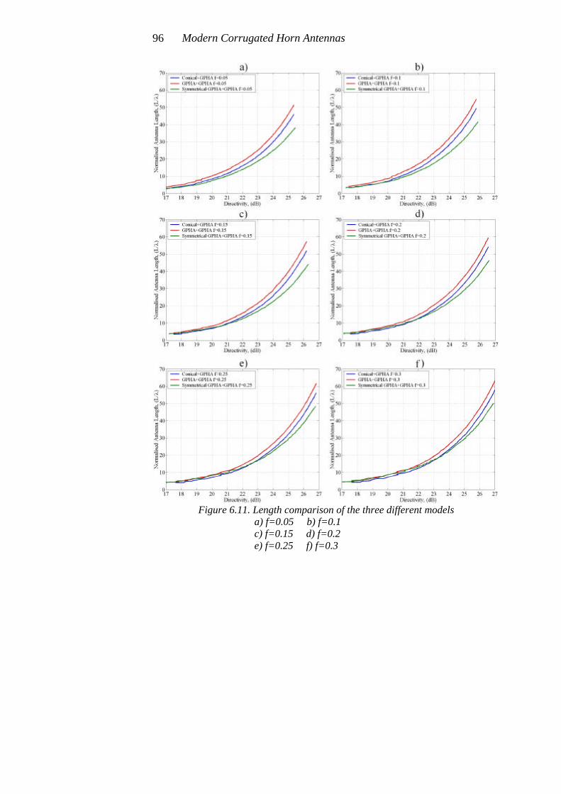
Modern Corrugated Horn Antennas 96
Figure 6.11. Length comparison of the three different models
a) f=0.05 b) f=0.1 c) f=0.15 d) f=0.2 e) f=0.25 f) f=0.3

Complete antenna design using corrugated GPHA’s 97
Figure 6.12. Output diameter comparison of three different models
a) f=0.05 b) f=0.1 c) f=0.15 d) f=0.2 e) f=0.25 f) f=0.3

Modern Corrugated Horn Antennas 98
Figure 6.13. Max. sidelobe level comparison of three different models
a) f=0.05 b) f=0.1 c) f=0.15 d) f=0.2 e) f=0.25 f) f=0.3
Complete antenna design using corrugated GPHA’s 99
6.5 Other possibilities to excite a corrugated GPHA
During the development of this chapter, we have proved that it is not
strictly necessary to use a perfect TE11 to HE11 mode converter at the input
of a corrugated GPHA. In fact, the really important idea is to provide at the
input of the second GPHA section a field that has as lower sidelobes as
possible, with equal beamwidths and low crosspolar level. The best feeding
field of a corrugated GPHA would be just a high purity gaussian beam.
This property of corrugated GPHA’s supposes some degree of
freedom to develop the design of the input section. In fact, we can make use
of another profiles that give a nice radiation pattern and cascade at their
aperture some section of a corrugated GPHA. These new designs will
usually provide shorter solutions. In the following paragraphs, two different
models are presented, all designs of the 22 dB directivity with –35 dB
sidelobe level will be considered.
6.5.1 Design of a 22 dB combination CSIRO [2] + GPHA
The people from CSIRO describe in [2] a complete antenna with a
corrugated GPHA as final section and a new short input profile. Their short
profile combines some properties from conical corrugated horn antennas
and other from symmetrical corrugated GPHA’s.
In figure 6.14 we can see that their profile can be divided in three main
parts. It assumes a quick and smooth change in the slope at the beginning,
(less than 10% of the total length), a conical profile to get quickly the
needed diameter (more than 65% of the total length), and a smoothed end to
connect to the corrugated GPHA second section (less than 25% of the total
length). It presents two main differences with the symmetrical GPHA
profile, at the input part the slope changes quicker, (nearly as in a conical

Modern Corrugated Horn Antennas 100
corrugated horn antenna), and at the final part doesn’t finishes with a flat
slope, it just closes a little the profile.
Figure 6.14. CSIRO profile for the input section of a complete corrugated GPHA
With this idea of a new corrugated input, the 22 dB directivity horn
antenna with –35 dB sidelobe level has been designed. In fact, the first part
of the combination symmetrical GPHA + GPHA of section 6.3.1 has been
directly substituted by a 6·λ long CSIRO profile with an output diameter of
3.48·λ and an input diameter of 0.78·λ. To design the CSIRO corrugated
profile, a polynomial has been defined to follow the curve. The parameters
of the second section corrugated GPHA have remained the same.
In figure 6.15 a reduction in length of 1.4·λ with respect to the antenna
of section 6.3.1 can be appreciated. This antenna also has the phase center a
little bit more inside (see figure 6.15) than the one in section 6.3.1, (a 21%
inside from the output aperture).
So, this is another possibility to design a shorter antenna using a new
corrugated profile section at the input part. The result is a more compact
antenna than the ones describe before. But the design method is not
completely described for this one, so the designer must play a little with the
parameters to obtain the final design.

Complete antenna design using corrugated GPHA’s 101
Figure 6.15. Combination CSIRO + GPHA with 22 dB directivity and –35 dB
sidelobe level
6.5.2 Design of a 22 dB combination Choked + GPHA
The most compact profile at the moment for a corrugated GPHA is the
one that uses at its input a choked waveguide corrugated profile [3, 4].
In fact, with this design method we obtain several advantages over the
other corrugated profiles, (see figure 6.16). The combination choked +
GPHA is the most compact antenna available in the actual technology. It
provides really excellent radiation patterns with extremely low sidelobes in
incredible compact profiles. Also the choked part has an easier manufacture
process avoiding the complicated λ/2 deep first corrugations of the other
corrugated profiles.
As a disadvantage, we must say that the maximum obtainable
bandwidth at the moment of these corrugated horn profiles is around 15%.

Modern Corrugated Horn Antennas 102
These choked corrugated GPHA’s are under research at the moment to
improve bandwidth.
Figure 6.16. Complete corrugated GPHA with a choked corrugated waveguide
input for 22 dB directivity and –40 dB sidelobe level
The antenna presented in figure 6.16 has a choked part of a ridiculous
1.26·λ length. The normalised inner diameter is of 0D =2.6 . The corrugated
GPHA final section has a length factor of f=0.633 and an output diameter
of 6.29·λ with an α=0.701.
The total length of the complete antenna is only 7·λ, a really incredible
compact profile and with 5 dB lower sidelobe level than the rest of the
designs of this chapter. The choked part is really short, but it doesn’t
provide a really nice output field, so the corrugated GPHA final section
must be longer than in the other profiles. But as the inner diameter is quite
small, the length of the second part is not to large.
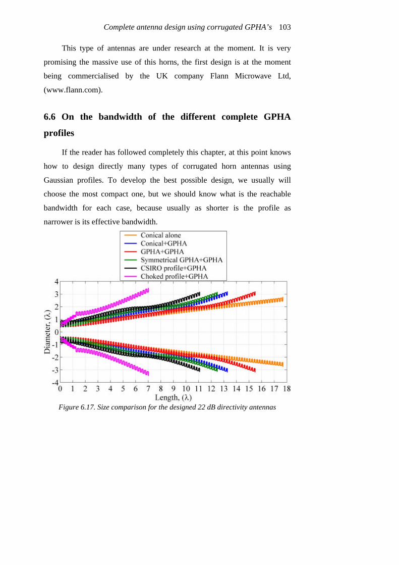
Complete antenna design using corrugated GPHA’s 103
This type of antennas are under research at the moment. It is very
promising the massive use of this horns, the first design is at the moment
being commercialised by the UK company Flann Microwave Ltd,
(www.flann.com).
6.6 On the bandwidth of the different complete GPHA
profiles
If the reader has followed completely this chapter, at this point knows
how to design directly many types of corrugated horn antennas using
Gaussian profiles. To develop the best possible design, we usually will
choose the most compact one, but we should know what is the reachable
bandwidth for each case, because usually as shorter is the profile as
narrower is its effective bandwidth.
Figure 6.17. Size comparison for the designed 22 dB directivity antennas

Modern Corrugated Horn Antennas 104
This bandwidth exercise is going to be made for the five 22 dB
corrugated antennas designed in this chapter, the conical corrugated horn
antenna design of chapter 3 will be added in the figures to facilitate the
comparison.
Figure 6.18. Bandwidth comparison between the different complete GPHA models
a) Return loss b) Maximum crosspolar level c) Directivity d) Normalised phase center position e) Maximum sidelobe level
Complete antenna design using corrugated GPHA’s 105
Figure 6.17 shows an antenna size comparison picture, including the
pure conical corrugated horn designed in chapter 3. The choked profile
GPHA is incredibly short and its wider output diameter is determined by the
–40 dB sidelobe level obtained for it, (see figure 6.16).
From figure 6.18, (this figure relates the bandwidth of every profile we
have designed), we can extract several conclusions:
• The return loss bandwidth is very nice for the choked + GPHA, (always
below –30 dB). For the rest of horn antennas is similar but slightly better
for the GPHA + GPHA and the symmetrical GPHA + GPHA. The
reason for this is the smoother throat section in these antennas.
• Regarding to crosspolar level (with λ/4 corrugation depth), the
bandwidth is similar in all the designs, except for the choked + GPHA
that presents a poorer bandwidth (around 10% bandwidth for –40 dB
crosspolar level). A slightly wider crosspolar level bandwidth for the
GPHA + GPHA, the symmetrical GPHA +GPHA and the CSIRO +
GPHA can be observed. In general, with corrugated antennas the
crosspolar level bandwidth can be improved with the information given
in the following section of this chapter.
• Figures 6.18c and 6.18d can be explained altogether because they are
strongly related. In figure 6.18c we can see the directivity bandwidth
curve for each design. It can be appreciated three different slopes.
- The lowest slope is found for the conical + GPHA and GPHA +
GPHA. Both of them provide a high efficiency HE11 at the inner
diameter. The phase centre of both (figure 6.18d) present also a
certain slope, this means that as higher the frequency is as more
inside the phase centre of the horn antenna is placed. In fact, a
phase centre variation going inside the antenna provides a

Modern Corrugated Horn Antennas 106
narrower diameter where the antenna effectively radiates. This
effect compensates a lot the slope of the directivity, but the phase
centre moves quite a lot also.
- Symmetrical GPHA + GPHA and CSIRO + GPHA present a
steeper slope in directivity. The reason for this behaviour depends
strongly on the lower purity of the HE11 mode at the inner
diameter. However, if we check the bandwidth curve of the phase
centre we see that both are flatter than the others. This means that
in fact this both designs are radiating from a single point phase
centre in most of the frequency band. The diameter of the horn at
phase centre remains the same, then the radiation pattern
controlled by this effective diameter changes the directivity
quicker with frequency.
- The choked + GPHA presents the steepest change in directivity as
well as the flattest phase centre position but in the narrowest
bandwidth.
• Maximum sidelobe level bandwidth always follows a slope that provides
lower sidelobe level for lower frequencies and higher sidelobe level for
higher frequencies in the band. This must be taken into account if we
need to maintain the sidelobe level, for example, below -35 dB along all
the usable bandwidth of the antenna. The choked GPHA has also a
poorer sidelobe level bandwidth.
So, summarizing we can conclude the following:
• The return loss bandwidth for corrugated GPHA’s can be one of the
most important problems to achieve bandwidths above 30%. This is
clearly not the case of the choked + GPHA profile, because it doesn’t
present return loss problems in a huge bandwidth despite it has poorer

Complete antenna design using corrugated GPHA’s 107
bandwidths in the rest of the radiation pattern parameters. A research on
this type of GPHA’s is being carried at present to improve the results.
• A compromise must be reached between maximum allowable change in
directivity along the usable bandwidth and maximum allowable
movement of the phase centre.
• Maximum sidelobe level must be chosen for a given profile to design
taken into account its bandwidth. The worst case sidelobe level will
always be the highest frequency in the band.
6.7 On the corrugation depth
During the development of the present manuscript, only a few
information has been given about corrugation depth. The corrugation depth
along the antenna was fixed to λ/4 in chapter 2 and no more considerations
about this critical design parameter have been taken into account.
This parameter controls the amount of crosspolar fields at a certain
frequency and its value affects the return loss. Nevertheless a small change
in corrugation depth ( ±25% ) will not change the copolar pattern, and its
radiating properties (directivity, sidelobe level…).
The balanced hybrid condition, (this condition means a corrugation
depth of λ/4), was used in chapter 2 to theoretically obtain a null in the
crosspolar component of the aperture fields. Practically, the real minimum
crosspolar value happens always for a corrugation depth a little bit deeper
than λ/4 and it is affected by the diameter of the corrugated waveguide. In
fact, for oversized aperture diameters, the minimum crosspolar corrugation
depth is practically equal to λ/4, but if the aperture diameter is not too
oversized (between 2·λ and 3·λ), the corrugation depth could be as much as

Modern Corrugated Horn Antennas 108
a 20% deeper than the commonly used λ/4 value to obtain a minimum
crosspolar level at the design frequency.
If we have a look to equation 2.1, it shows that the crosspolar term
decreases as k R⋅ increases (with R the output aperture radius of our horn
antenna). So the larger the aperture diameter of the horn, the wider will be
the bandwidth for a given crosspolar level, because the term X-Y in that
equation will never vanish except theoretically at a single frequency.
Figure 6.19. Directivity versus approximate obtainable maximum crosspolar level
(constant corrugation depth at λ/4)
The figure 6.19 shows the approximate obtainable crosspolar levels for
a corrugated horn antenna with exactly λ/4 corrugation depth. The line is
quite broad because the different possibilities of output diameter for a given
directivity have been taken into account.
An important conclusion of the figure 6.19 is that it is easier to obtain
a low crosspolar level antenna for a 22 dB directivity antenna than for a
18 dB directivity antenna. For example, to obtain a –45 dB crosspolar level
in a 18 dB directivity antenna is quite complicated, any of the considered
Complete antenna design using corrugated GPHA’s 109
designs could satisfy that condition. Perhaps, with a corrugation depth
slightly above λ/4 it will probably fulfil the requirement within a reduced
bandwidth. On the other hand to obtain –45 dB crosspolar level with a
22 dB directivity antenna (wider aperture diameter) should not be a problem.
6.8 Design tricks and rules
If everything has been reasonably understood until this point, the
reader is now capable of designing a corrugated GPHA that best meets his
specifications.
The obtainable antenna with the aid of this chapter 6 for sure will not
be the optimal solution. However the best and final profile must start from
that first approximation. In this section some design rules to help the
designer to quickly obtain the final corrugated profile that best meets his
specifications in a quite compact design will be explained.
First of all, the designer must know that there are two types of
parameters, both nearly independent, that affect the design:
1. The profile shape will affect directivity and sidelobe level. In fact it will
affect quite exclusively only to the copolar radiation pattern, (with the
exception if the profile shape does not change smoothly).
2. The corrugation parameters affect crosspolar level and return loss, and
not to copolar features.
These last properties allow the designer to practically separate the
design in two parts; first of all the designer adapts exactly the copolar
pattern, and after that lowers the crosspolar radiation and the return loss by
means of the corrugation parameters.

Modern Corrugated Horn Antennas 110
6.8.1 Reducing the size of the complete corrugated GPHA
To make a more compact profile we must change the profile shape.
After the design given by the empirical formulas of this chapter, a “rule of
thumb” that works consists in shortening the input section corrugated
GPHA, (if it is a conical corrugated section, making slightly bigger its
profile angle; if it is a corrugated GPHA input, making slightly smaller the
α parameter), but maintaining approximately the same inner diameter. The
way this technique works is usually shortening the input section two
corrugation periods and lengthening the second section GPHA one
corrugation period. So the total shortening effect is one corrugation period
per step. Usually this technique also assumes making the inner diameter
slightly smaller and using an α parameter for the second GPHA section
slightly bigger so that the output diameter doesn’t increase. Usually with
this technique we can reduce the total length, three, four or perhaps more
corrugation periods.
6.8.2 Reducing the crosspolar level and the return loss of any
corrugated horn antenna
Once we have completely defined a corrugated horn antenna profile, to
reduce the crosspolar level and the return loss of the profile, we must
redesign the corrugations.
Usually we will have exactly a corrugation depth of λ/4 along the
profile and a matching device at the beginning of the horn starting with a
corrugation depth of λ/2 that diminishes in certain length linearly to λ/4.
This corrugation depth change at the throat has a length that is exactly the

Complete antenna design using corrugated GPHA’s 111
distance where the inner diameter corrugation allows the TM11 mode to be
in propagation, so a inner diameter of exactly 1.22·λ.
If we make the length of the transformer of corrugation depth between
λ/2 to λ/4 a little bit longer than this theoretical value (10-20% longer), the
return loss will be improved in bandwidth, but the crosspolar level will be
poorer. And if we make it shorter, just the opposite will happen. Thus a
compromise between return loss and crosspolar level in the whole frequency
bandwidth must be reached.
If we make the first corrugation depth slightly deeper, probably the
return loss will be improved and the crosspolar level not much affected, but
this means more manufacture problems. In fact, usually to reach a λ/2 first
corrugation depth is impossible by means of a milling machine manufacture
technique, so another solution should be found.
Figure 6.20. Different methods to improve the return loss bandwidth of a
corrugated horn antenna a) Variable corrugation tooth width at the throat b) Ring loaded slots in the first corrugations at the throat

Modern Corrugated Horn Antennas 112
Corrugation period and corrugation tooth width usually doesn’t affect
too much to any radiation parameter (see appendix II), except at the throat
region. For the rest of the antenna a corrugation period around λ/5 and a
corrugation tooth with around p/2 or slightly thinner (p/3 where p is the
corrugation period) are usually the best values and don’t need to be
changed. Usually corrugation widths must be chosen to minimise the
manufacture problems, a variable corrugation period or a variable
corrugation width complicates quite a lot the manufacturing process.
In figure 6.20 we present two ways to reduce the return loss of the
antenna not affecting too much to the crosspolar radiation. Both methods
complicate quite a lot the manufacture process, in fact the ring loaded slots
are nearly impossible to implement unless the throat is made by means of
stacking metallic pieces. This is one of the clear advantages of the choked
profiled input GPHA which is under research at the moment because it
reduces a lot the complexity in the manufacture process at the throat region,
(probably the most difficult part to manufacture in a corrugated horn
antenna).
Once we have defined the throat region that best meets our return loss
and manufacture requirements, we must choose the optimum corrugation
depth for the rest of the antenna (this depth is usually slightly above λ/4)
that best reduces the crosspolar level.
A technique that works quite well to reduce the crosspolar level is to
use a tapered corrugation depth. This means that inside of the antenna the
corrugation depth could be 10-15% smaller than λ/4, and as we approach to
the aperture the corrugation depth increases above λ/4. The reason for this
technique is that at high frequencies of the band the outer part of the antenna

Complete antenna design using corrugated GPHA’s 113
is not effectively seen by the radiated fields, so it is not affected by deep
corrugation depths at the output aperture. However low frequencies of the
usable bandwidth are affected by the whole antenna profile.
Fortunately, a tapered change in corrugation depth doesn’t complicate
the antenna manufacture process. This technique provides a quite flat
crosspolar pattern (no deep crosspolar values), but it could be easy to
achieve for example -45 dB crosspolar level in a 22 dB directivity antenna in
more than a 30% bandwidth.
However, due to the fact of the continuously increased speed in
computers, usually a good optimisation code reduces the optimum design
time and complexity really a lot. It is usually the best tool to be used to
implement the final design without the need of being continuously changing
parameters in the design [1].
6.9 References
[1] R. García Esparza, “Optimización de los parámetros de antenas de
bocina corrugadas de perfil gaussiano mediante Matlab” Research to
obtain the Spanish master degree on Telecommunications Engineering,
November 2001, Universidad Pública de Navarra, Pamplona, Spain
[2] S.G. Hay, S.J. Barker, C. Granet, A.R. Forsyth, T.S. Bird, M.A. Sprey
and K.J. Greene, “Multibeam Earth Station Antenna for a European
Teleport Application” 2001 IEEE AP-S International Symposium and
URSI Radio Science Meeting, 8-13 of July, Boston, United States.
[3] Teniente, J., Goñi, D., Gonzalo, R. and del Río, C. “Choked Gaussian
Antenna: Extremely Low Sidelobe Compact Antenna Design”, IEEE

Modern Corrugated Horn Antennas 114
Antennas and Wireless Propagation Letters, vol. 1, nr. 11, pp. 200-202,
November 2002.
[4] Gonzalo, R., del Río, C., Goñi, D. and Teniente, J., “Antena de bocina
que combina corrugaciones horizontales y verticales” Spanish Patent
Nr: P.2002 01264 Property of: Public University of Navarra, (UPNA),
24th of May 2002.

Chapter 7
Applications of corrugated GPHA
During the development of this Ph. D., many corrugated GPHA have
been designed and some have been manufactured. In fact, the number of
designed corrugated GPHA’s is above one hundred and the number of
manufactured ones above ten.
During the last six years we have been refining the design method
until we have reached the design path we propose in the previous chapters
of this thesis. Many antennas have been manufactured and measured
obtaining really good results during this long developing time.
The first corrugated GPHA’s we manufactured by means of
electroforming and they were two millimeter wave horn antennas [1], one
was a direct corrugated GPHA and the other a symmetrical corrugated
GPHA. The measured results were very nice, validating our numerical
design code, year 1996. At the same time, an antenna for the German
company Reinhold Mühleisen (RM), was designed to work at 170 GHz and
was integrated in a complete system for the Japan Atomic Research
Institute.
In 1997 we designed, manufactured and measured a high directivity
corrugated GPHA to emulate the radiation of the TJ-II gyrotron and test a
quasi-optical transmission line at low power in the CIEMAT in Madrid
[2,3].
In 1998, the design of the Hispasat 1C satellite horn antenna was
performed. At the beginning of this year we managed to persuade the

Modern Corrugated Horn Antennas 116
engineers of CASA/EADS to use, for one of the three horns to be on board
of Hispasat 1C satellite, a new technology based on corrugated GPHA’s [4],
this satellite was launched on February 2000. The nice performance of this
antenna was the reason to be also selected to be on board of the new
Hispasat 1D satellite launched in September 2002 with a slightly different
frequency band.
The next antenna design to be manufactured had to be two years later.
In the year 2000 we designed two sub-millimetre horn antennas of very high
directivity and very low sidelobe level for the Rutherford Appleton
Laboratory in England. They manufactured them by means of high precision
electroforming and will be a part of ESA funded MARSCHALS airborne
system.
In the year 2000 we were also involved in the design of the corrugated
horn antennas for the Low Frequency Instrument (LFI) for the Planck
satellite with the contacts with the people from the CNR in Bologna, Italy.
In fact, all the horn antennas for the Planck satellite, (HFI and LFI) use
corrugated GPHA’s. The High Frequency Instrument (HFI) corrugated
horns were developed by the people from the Queen Mary College in
London, U.K. where the corrugated horn technology was firstly developed
during the seventies [5,6]. The Planck mission is an ESA funded mission to
look at microKelvin anisotropies in the 2.7ºK cosmic background radiation
Also year 2000 was the year of the international recognition of the
good radiating properties of our GPHA designs by other authors [5,6,7].
People of the most important horn antenna research groups in the world
began to use our corrugated GPHA designs for their own designs (Queen
Mary College, CSIRO, Jet Propulsion Laboratory, CNR Bologna, etc.).
Applications of corrugated GPHA 117
In the year 2001 we developed a set of corrugated GPHA’s of very
wide bandwidth [8] to be used in our anechoic chamber project. Then, a
wide band measurement will be possible without changing the feed horn of
the chamber.
Year 2002 was the year of the development of the new hybrid
corrugated horn called the choked waveguide GPHA. This antenna provides
a really nice radiation pattern in the most compact profile ever designed. It
has entered the market with an important company as Flann Microwave
Ltd., (http://www.flann.com/Sales/Feature_Article/feature_article.html) [9]
This antenna is our last successful research, and an improvement to it is
under development at the moment.
In this chapter of the thesis, all of these practical examples of complete
corrugated GPHA’s are going to be covered. We will understand the way
how this important corrugated horn antennas has been carried on during the
years of development of the present thesis.
7.1 Corrugated GPHA design for low power testing of the
quasioptical transmission lines at TJ-II stellerator
During 1996, the need to test a quasioptical transmission line used to
drive the very high power millimeter wave beam from the gyrotron
generators to the TJ-II plasma at the CIEMAT in Madrid [2,3] gave us the
opportunity to design one of the first corrugated GPHA for a practical
application.
The gyrotron output (53.2 GHz) had a 95% efficiency to a
fundamental gaussian beam of 18 mm beamwaist. So our design parameters

Modern Corrugated Horn Antennas 118
were to provide the most similar gaussian beam radiation pattern to that
gaussian beam at 53.2 GHz.
A fundamental gaussian beam of w0=18 mm at 53.2 GHz means a
29.6 dB directivity radiation pattern with as low sidelobes as possible to
obtain high efficiency. Such a high directivity for a corrugated horn antenna
led to a huge profile.
Figure 7.1 a) Antenna design to get a 18 mm fundamental gaussian beam
b) Simulated far field radiation pattern for the antenna

Applications of corrugated GPHA 119
In 1996, corrugated GPHA theory was in its infancy, so the design we
made, was far away from the optimum, but it worked nicely to test the
quasioptical waveguide. To develop the design we knew that the end part
had to be a gaussian aperture corrugated horn with an α value around
0.6-0.7 and we also knew that the input diameter (D0) of such a gaussian
part had to be between 8·λ-9·λ to obtain the needed directivity to match
efficiently a 18 mm beamwaist fundamental gaussian beam. Our design
problem came because in the year 1996 we didn’t know yet how to obtain a
nice HE11 mode in such a huge diameter in a short profile.
The design requirements were to obtain a 18 mm beamwaist
fundamental gaussian beam at 53.2 GHz in the most compact and easiest to
manufacture profile beginning from a smooth circular waveguide of 4.8 mm
diameter propagating the TE11 mode.
Figure 7.2 Manufactured antenna prepared to test the quasioptical transmission
line at CIEMAT

Modern Corrugated Horn Antennas 120
The antenna was made by means of dividing it in three parts, (see
figure 7.1a). The design frequency was 53.2 GHz :
- The first part was a symmetrical GPHA TE11 to HE11 mode converter with
an output diameter of only 1.67·λ and an α=1.61.
- The second part was a modified Dolph-Chebyshev taper that maintained
the HE11 mode from the 1.67·λ output diameter of the first section to an
8.87·λ output diameter. The length of this taper was huge, 52.17·λ (see
figure 7.1a).
- The third part was a corrugated GPHA with a 0D =8.87 , α=0.6 and
f=0.05 resulting in an output diameter of 11.36·λ.
The corrugation parameters were; corrugation period p=2 mm,
corrugation tooth width w=p/2=1 mm and corrugation depth d=λ/4. At the
throat, a λ/2 to λ/4 impedance transformer of 1.53·λ length was also used to
adapt the TE11 mode at the input.
Figure 7.3 Measured radiation pattern of CIEMAT corrugated GPHA antenna at
53.2 GHz

Applications of corrugated GPHA 121
The antenna was manufactured by Thomas Keating Ltd. by means of
electroforming, (see figure 7.2) and measured in the ESA/ESTEC Compact
Antenna Test Range (CATR). Measurement and simulations are in very
good agreement, see figure 7.1 and 7.3.
This antenna was used to test the high power quasioptical waveguide
of the TJ-II stellerator obtaining nice results previous to connect the high
power gyrotron [2,3].
Now-a-days, a much more compact antenna (around 20·λ shorter)
could have been designed, with an efficiency to the 18 mm beamwaist
fundamental gaussian beam above 99% and lower sidelobe and crosspolar
levels maintaining approximately the same output diameter.
7.2 Corrugated GPHA design for Hispasat 1C satellite
At the end of year 1997, the antenna engineers from CASA/EADS
space division proposed to our research group to collaborate in the design of
the three corrugated horn antennas that were going to be on board of the
Hispasat 1C satellite.
We had the specifications of the three antennas, but we put the effort
in the design of two of them.
The specifications for the first antenna were the following (uplink and
downlink for America antenna):
• Frequency range: from 11.9 to 12.2 GHz and from 13.75 to 14 GHz
• Illumination at 19 degrees below -22 dB
• Maximum crosspolar level below -45 dB
• Return loss below -28 dB
Modern Corrugated Horn Antennas 122
• Input diameter 23.4 mm
• Corrugation period, p=3.4 mm and corrugation tooth width, w=0.9 mm
• First corrugation depth below 11 mm
The specifications for the second antenna were the following
(downlink for Europe antenna):
• Frequency range: from 11.7 to 12.2 GHz
• Illumination at 19 degrees below -22 dB
• Maximum crosspolar level below -45 dB
• Return loss below -28 dB
• Input diameter 23.4 mm
• Corrugation period, p=3.4 mm and corrugation tooth width, w=0.9 mm
• First corrugation depth below 11 mm
The third antenna was used for the uplink to Europe and the frequency
range was from 13 to 13.25 GHz and from 13.75 to 14 GHz.
The first two antennas had exactly the same specifications except that
the frequency range began in 11.7 GHz in the second one instead of
11.9 GHz and that the first antenna had another band from 13.75 to 14 GHz.
So we decided to design an antenna that could cover both designs in the
same profile extending the frequency range in our design from 11.7 to
12.2 GHz and from 13.75 to 14 GHz.
An illumination at 19 degrees at exactly –22 dB means a directivity of
22.475 dB exactly (see appendix III), if the antenna radiation pattern is
similar to a fundamental gaussian beam. So if we must comply with this
requirement, we should design the antenna to present a 22.5 dB directivity at
11.7 GHz.

Applications of corrugated GPHA 123
But in this design, sidelobes can be as high as –22 dB in fact because
no sidelobe level restriction has been required, so this restriction is
superimposed by the illumination at 19 degrees to be below –22 dB. This
will mean that we will design the antenna to present at 14 GHz exactly
-22 dB sidelobe level to provide the most possible compact profile. To
present a so high sidelobe level will mean that the needed directivity at
11.7 GHz to provide the exact illumination will be lower than the theoretical
value of 22.5 dB because the high sidelobes will reduce the directivity
although the main beam decay will mean a higher directivity to match the
illumination.
With all this information, and because the complete bandwidth was
quite large (around 18%), we decided to implement the best bandwidth
design, a corrugated GPHA input as mode converter followed by a short
corrugated GPHA output part (GPHA + GPHA).
After the optimisation of the profile, these were the resultant
parameters:
q Design frequency: 11.7 GHz.
q Input diameter: 23.4 mm
q Corrugation parameters: p=3.4 mm, w=0.9 mm and d=6.4 mm
q First GPHA part:
§ α=2.017 § Length=88·p (299.2 mm).
§ 0D =4.106
§ Impedance transformer - Length=60 mm - 1st corrugation depth=11 mm
q Second GPHA part: § α=0.686
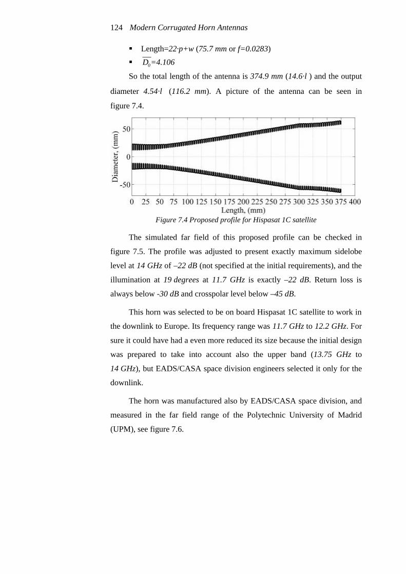
Modern Corrugated Horn Antennas 124
§ Length=22·p+w (75.7 mm or f=0.0283)
§ 0D =4.106
So the total length of the antenna is 374.9 mm (14.6·λ) and the output
diameter 4.54·λ (116.2 mm). A picture of the antenna can be seen in
figure 7.4.
Figure 7.4 Proposed profile for Hispasat 1C satellite
The simulated far field of this proposed profile can be checked in
figure 7.5. The profile was adjusted to present exactly maximum sidelobe
level at 14 GHz of –22 dB (not specified at the initial requirements), and the
illumination at 19 degrees at 11.7 GHz is exactly –22 dB. Return loss is
always below -30 dB and crosspolar level below –45 dB.
This horn was selected to be on board Hispasat 1C satellite to work in
the downlink to Europe. Its frequency range was 11.7 GHz to 12.2 GHz. For
sure it could have had a even more reduced its size because the initial design
was prepared to take into account also the upper band (13.75 GHz to
14 GHz), but EADS/CASA space division engineers selected it only for the
downlink.
The horn was manufactured also by EADS/CASA space division, and
measured in the far field range of the Polytechnic University of Madrid
(UPM), see figure 7.6.

Applications of corrugated GPHA 125
Figure 7.5 a) b) c) d) e) Simulated far field radiation pattern for proposed
Hispasat 1C satellite profile antenna f) Simulated far field parameters for proposed Hispasat 1C satellite
profile antenna

Modern Corrugated Horn Antennas 126
Measured results are in really good agreement with simulated ones,
(see figure 7.6), with measured crosspolar pattern always below –40 dB and
copolar pattern exactly the same as the simulated one (see figure 7.5 to
compare).
Figure 7.6 a) Manufactured antenna at UPM far field range
b) c) d) Far field radiation pattern measurements
Hispasat 1C was launched in February 2000 with this corrugated
GPHA. The antenna behaviour was so nice that was selected exactly the
same profile (not a scaled version) to be on board also of the new
Hispasat 1D satellite that was launched in September 2002 to serve for the
downlink to Europe but with a wider frequency band (from 11.45 to
12.75 GHz).

Applications of corrugated GPHA 127
7.3 Corrugated GPHA feedhorns for ESA funded
MARSCHALS airborne system
In the year 2000, the engineers from the Millimetre Technology Group
of the Rutherford Appleton Laboratory (RAL) in England asked us to design
two sub-millimetre wave corrugated horn antennas for the ESA funded
MARSCHALS airborne system. MARSCHALS is a three channel limb
sounder for the European Space Agency (ESA) that will fly on an aircraft.
The engineers of the Millimetre Technology Group at RAL were
specially concerned about the sidelobes generated by the feedhorns or the
rest of the optics. The aim of the MARSCHALS project is the limb
observation, and therefore any power introduced via a sidelobe pointing the
earth should be consider as noise decreasing the performance of the whole
system. They asked for –35 dB sidelobe level in both feedhorn designs, and
this is just the perfect requirement for a corrugated GPHA.
The requirements for these corrugated horn antennas (called antenna in
band C and antenna in band D), were the following:
Band Frequency Range Centre Frequency Beamwaist Radius
C 316.5 - 325.5 GHz 321.00 GHz 2.078 mm
D 342.2 - 348.8 GHz 345.50 GHz 2.003 mm
Table 7.1 MARSCHALS feedhorns requirements
Other parameters common to both antennas were the following:
- Sidelobes: It was required sidelobes to be less than -35dB (with no
"shoulders" on the main lobe). Obviously the lower the better.
- Peak crosspolar: below -35dB (again, the lower the better)
- Feed waveguide: Full height rectangular waveguide (0.762 x 0.381 mm)

Modern Corrugated Horn Antennas 128
- Horn Length (flange to aperture): Maximum 40 mm.
Another requirement was that they wanted to manufacture the
complete corrugated horns by means of high precision electroforming
including the rectangular to circular transition to the rectangular feed
waveguide of 0.762 x 0.381 mm dimension. To reduce the manufacture
complexity, the corrugation tooth width should be exactly half of the
corrugation period and the constant along the whole antenna.
The bandwidth requirements were not too tight, 2.8% for the C band
antenna and 1.9% for the D band antenna, so we decided to use a corrugated
antenna with a symmetrical gaussian profile followed by a pure gaussian
output for the design.
The directivity, by means of translation of the beamwaist radius values
was very high; 2.078 mm beamwaist radius at 321 GHz in C band antenna
means an illumination at 16 degrees of –35 dB and therefore a directivity of
26 dB. As well, the 2.003 mm beamwaist radius at 345.5 GHz in C band
antenna means an illumination at 15.5 degrees of –35 dB and therefore a
directivity of 26.3 dB.
The transition from rectangular to circular waveguide was designed
ending in a circular diameter of 0.762 mm. This was used as the input
waveguide diameter for both antennas.
After the optimisation of both profiles, these were the resultant
parameters:
C band antenna
q Design frequency: 321 GHz. Input diameter: 0.762 mm
q Corrugation parameters: p=0.2 mm, w=0.1 mm and d=0.24 mm
q First symmetrical GPHA part:
§ α=2.669

Applications of corrugated GPHA 129
§ Length=134·p (26.8 mm).
§ 0D =5.679
§ Impedance transformer - Length=5 mm. - 1st corrugation depth=0.48 mm
q Second GPHA part: § α=0.73 § length=67·p+w (13.5 mm)
§ 0D =5.679
§ f=0.192 with suppression of the first 6 corrugation periods of this part, thus the resultant effective length is 12.3 mm
The total length of the antenna is 39.1 mm (41.9·λ) and the output
diameter 8.29·λ (7.74 mm). A picture of the antenna is shown in figure 7.7a.
D band antenna
q Design frequency: 345.5 GHz. Input diameter: 0.762 mm
q Corrugation parameters: p=0.2 mm, w=0.1 mm and d=0.22 mm
q First symmetrical GPHA part:
§ α=2.62 § Length=136·p (27.2 mm).
§ 0D =5.972
§ Impedance transformer - length=5 mm. - 1st corrugation depth=0.44 mm
q Second GPHA part: § α=0.73 § length=66·p+w (13.3 mm)
§ 0D =5.972
§ f=0.18 with suppression of the first 7 corrugation periods of this part, thus the resultant effective length is 11.9 mm

Modern Corrugated Horn Antennas 130
The total length of the antenna is 39.1 mm (45.1·λ) and the output
diameter 8.53·λ (7.398 mm). A picture of the antenna is shown in
figure 7.7b.
Figure 7.7 a) MARSCHALS feedhorn proposed profile for C band
b) MARSCHALS feedhorn proposed profile for D band
The rectangular to circular transition design was very simple and it
was a direct cut of 15 degrees angle of the circular input waveguide of each
antenna in a 0.711 mm length to result in the 0.762 x 0.381 mm input
rectangular waveguide, (see figure 7.8).
Figure 7.8 MARSCHALS feedhorns throat region with rectangular to circular
transition

Applications of corrugated GPHA 131
The antenna was manufactured by the workshop of the Millimetre
Technology Group at RAL using a electroforming technique. The mandrel
was made by a milling machine and a picture of it can be seen in figure 7.9.
Observe in that figure the extremely high precision manufacturing
remembering that the corrugation tooth width is only 0.1 mm.
Figure 7.9 Mandrel of one of the MARSCHALS feedhorns
Frequency 316.5 GHz 321 GHz 325.5 GHz
Return loss -38.939 dB -42.102 dB -46.567 dB
Directivity 25.717 dB 25.857 dB 25.988 dB
Phase centre posit. (relative to apert.) -4.901 mm -5.011 mm -5.103 mm
Beamwaist radius, (w0) 2.107 mm 2.115 mm 2.115 mm
Efficiency to w0 Gaussian Beam 99.587 % 99.556 % 99.547 %
Efficiency to 2.078 mm beamwaist
fundamental gaussian beam 99.521 % 99.492 % 99.465 %
Maximum crosspolar level -56.302 dB -53.542 dB -49.221 dB
Maximum sidelobe level -37.128 dB -36.11 dB -35.801 dB
16 deg edge taper (45 deg plane) -31.1 dB -32.3 dB -34.1 dB
Table 7.2 MARSCHALS C Band feedhorn radiation behaviour

Modern Corrugated Horn Antennas 132
At present time we don’t have yet the measurement of both antennas,
but for sure will be really near to the simulations. Simulations of both
antennas at central frequency can be found in figure 7.10 and tables 7.2 and
7.3 extract the main far field parameters.
Frequency 342.2 GHz 345.5 GHz 348.8 GHz
Return loss -40.187 dB -42.009 dB -44.386 dB Directivity 26.117 dB 26.206 dB 26.296 dB
Phase centre posit. (relative to apert.) -4.659 mm -4.77 mm -4.882 mm Beamwaist radius, (w0) 2.057 mm 2.059 mm 2.062 mm
Efficiency to w0 Gaussian Beam 99.482 % 99.446 % 99.424 % Efficiency to 2.003 mm beamwaist
fundamental gaussian beam 99.356 % 99.312 % 99.287 %
Maximum crosspolar level -56.933 dB -53.441 dB -49.947 dB Maximum sidelobe level -35.394 dB -34.835 dB -34.566 dB
15.5 deg edge taper (45 deg plane) -33.5 dB -34.55 dB -35.5 dB Table 7.3 MARSCHALS D Band feedhorn radiation behaviour
Figure 7.10 Simulated far field radiation pattern of both MARSCHALS feedhorns

Applications of corrugated GPHA 133
Both antennas meet all the specifications widely (see figures 7.10 and
7.11). The shoulder that is slightly noticed in figure 7.10a and 7.10b for both
antennas presents a very low importance. In fact, the difference between the
no-shoulder slope gaussian decay and the maximum shoulder slope is in the
worst case below 5 degree.
Figure 7.11Simulated far field behaviour of both MARSCHALS feedhorns
7.4 Ultra wide band corrugated GPHA design for the far field
range measurement chamber at UPNA
In the year 2000 we were concerned about what would be the
maximum bandwidth we could achieve with a corrugated GPHA. At that
year, we were developing a project to build an antenna measurement
chamber in our laboratory in the Public University of Navarra, (UPNA). A
design to obtain the maximum achievable bandwidth was selected to
overcome the annoying problem of the necessity to change the feedhorns
each time it is necessary to cover a large frequency bandwidth antenna
measurement.
The design was performed to accomplish an ultra-wide bandwidth
(more than 40 %), with low side-lobe and cross-polar levels. The selected
frequency bands were X and Ku. A WR75 waveguide was selected in order

Modern Corrugated Horn Antennas 134
to cover the frequency range from 9 to 16 GHz. A directivity around 21 dB
at the central frequency (12-13 GHz) was chosen, in order to illuminate the
wider part of the far field range and allow measurement of bigger antennas.
Figure 7.12 Ultra wide bandwidth corrugated GPHA profile
The optimised corrugated GPHA design, to cover the wide bandwidth
requirement is formed by two corrugated GPHA stacked together. The
design has the following parameters:
q Design frequency: 11.63 GHz.
q Input diameter: 23.2 mm
q Corrugation parameters: p=6 mm, w=2 mm and d=6.45 mm
q First GPHA part:
§ α=2 § Length=35·p (210 mm).
§ 0D =3.02
§ Impedance transformer - Length=60.2 mm - 1st corrugation depth=12 mm
q Second GPHA part: § α=0.58,

Applications of corrugated GPHA 135
§ length=12·p+w (74 mm or f=0.089).
§ 0D =3.02
So the total length of the antenna is 284 mm (11·λ) and the output
diameter 4.62·λ (119.2 mm). A picture of the antenna can be seen in
figure 7.12.
To allow connection of this corrugated GPHA to a WR75 waveguide
system, a Flann Microwave Ltd. rectangular to circular transition from
WR75 rectangular waveguide to 9.5 mm circular waveguide radius was used.
The connection of this transition to the corrugated GPHA input (11.6 mm)
was not optimized at it shows a small step at the beginning of the
corrugations, see figure 7.12.
This antenna was manufactured in aluminum by the company
TMM Micromecánica (Oricain-Navarra). The antenna was measured in
ESA/ESTEC Compact Antenna Test Range, and the results were really fine.
Figure 7.13 a) Simulated and measured return loss for the corrugated GPHA
b) Measured maximum crosspolar level for the corrugated GPHA
Measured input return loss (including the rectangular to circular
converter and a coaxial to waveguide transition) values below -18 dB were
obtained from 11 GHz to 14 GHz. These results are in good agreement with

Modern Corrugated Horn Antennas 136
the simulated ones obtained by using ANSOFT-HFSS finite element code
(see figure 7.13a).
Figure 7.14 Measured far field radiation pattern for this ultra wide
bandwidth corrugated GPHA
Applications of corrugated GPHA 137
The antenna shows a measured maximum cross-polar level below
-30 dB from 9 to 14.8 GHz, (49% bandwidth), and below –35 dB from
10.6 to 14.4 GHz, (more than 30 % bandwidth), see figure 7.13b. Figure 5.7
depicts the radiation pattern in 1 GHz steps for the whole band. High
symmetry patterns with directivity values from 19 to 22 dB along the band
have been obtained. Also it should be noted that the sidelobe levels are
below –28 dB from 9 to 15 GHz.
This corrugated GPHA will be perfect as a feedhorn for our future far
field measurement chamber at UPNA. Return loss is not a critical parameter
in a measurement chamber, and crosspolar levels are in fact only important
at the center of the beamwidth (effective radiation area that receives the
measured antenna in a far field chamber). Crosspolar levels for ± 5 deg are
always below –38 dB, (see figure 7.14), for a 50% bandwidth (9 to 15 GHz).
Huge bandwidth measurements are then possible.
A complete set of antennas has been manufactured for the chamber, in
fact the complete set are five identical corrugated GPHA’s scaled for each
band covering from 7 GHz to 26.5 GHz. The feedhorns overlap half of its
bandwidth with the upper band feedhorn and the other half with the lower
band feedhorn, so that we will have the possibility to select the perfect
feedhorn for every antenna measurement in the chamber.
7.5 Choked corrugated GPHA. Extremely compact low
sidelobe antenna design
Extremely low sidelobe horn antennas are often required for many
current applications. This type of horn antennas are really important now-a-
days to avoid interference with other communication systems. Because of

Modern Corrugated Horn Antennas 138
that, many research groups around the world are at present trying to redo the
invention of the wheel [10,11]. Other groups just use our idea of corrugated
GPHA at the output of any nice radiation pattern antenna that need to be
improved in sidelobe level [6].
Recently, a compact corrugated horn antenna design proposed by
Granet et al. [10] exhibiting low sidelobes for global earth coverage
applications has been presented. In particular, this horn antenna design has
sidelobes values of -36 dB and a total length of 5.6λ and global earth
coverage assumes a directivity around 21 dB at central frequency. This
antenna presents a really nice radiation pattern in a very compact size and
doesn’t make use of GPHA profiles, but it exhibits two principal
disadvantages: a narrow bandwidth (less than 5% for –30 dB sidelobe level,
–30 dB crosspolar level and –20 dB return loss) and it is very sensitive to
manufacturing tolerances in the throat region (mode generator) [11]. This
antenna can be reclassified better as being a radiating resonator not an
antenna because it works really nice for a 1% bandwidth.
Granet et al describe in [10] a corrugated horn antenna presented by
our group [12]; they say that they designed a 17.4º half-power beamwidth
(this means 20.95 dB directivity and global earth coverage from a
geoestationary satellite, see appendix III) corrugated GPHA with 8.92·λ
length obtaining a -33 dB sidelobe level and a -40dB maximum crosspolar
level. They assumed that this was the best antenna one can design with
gaussian techniques. But as we have seen in this thesis, this is not
completely true because with a Gaussian profile [13] sidelobe levels can be
lowered much more and probably the length can be also improved. In fact,
with the formulas of chapter 6, we can design directly a complete corrugated
GPHA with sidelobe levels below -40 dB in a 9·λ length and with a
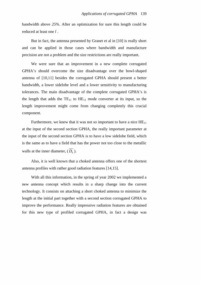
Applications of corrugated GPHA 139
bandwidth above 25%. After an optimization for sure this length could be
reduced at least one λ.
But in fact, the antenna presented by Granet et al in [10] is really short
and can be applied in those cases where bandwidth and manufacture
precision are not a problem and the size restrictions are really important.
We were sure that an improvement in a new complete corrugated
GPHA’s should overcome the size disadvantage over the bowl-shaped
antenna of [10,11] besides the corrugated GPHA should present a better
bandwidth, a lower sidelobe level and a lower sensitivity to manufacturing
tolerances. The main disadvantage of the complete corrugated GPHA’s is
the length that adds the TE11 to HE11 mode converter at its input, so the
length improvement might come from changing completely this crucial
component.
Furthermore, we knew that it was not so important to have a nice HE11
at the input of the second section GPHA, the really important parameter at
the input of the second section GPHA is to have a low sidelobe field, which
is the same as to have a field that has the power not too close to the metallic
walls at the inner diameter, ( 0D ).
Also, it is well known that a choked antenna offers one of the shortest
antenna profiles with rather good radiation features [14,15].
With all this information, in the spring of year 2002 we implemented a
new antenna concept which results in a sharp change into the current
technology. It consists on attaching a short choked antenna to minimize the
length at the initial part together with a second section corrugated GPHA to
improve the performance. Really impressive radiation features are obtained
for this new type of profiled corrugated GPHA, in fact a design was

Modern Corrugated Horn Antennas 140
included in chapter 6 and the choked waveguide TE11 to HE11 mode
generator was briefly explained in chapter 5.
The first antenna design we developed with this new technology was
manufactured and measured and in fact this profile has been further
improved now-a-days. The UK company Flann Microwave, Ltd. includes it
in their catalog at any frequency band.
The design was performed to accomplish a very short antenna
(length<6.5·λ) with very low sidelobes (lower than -40 dB at central
frequency) and with low crosspolarization, and as much as possible
bandwidth. The illumination is fixed to be -3 dB at 8.7 degrees half
beamwidth (the angle subtended by the earth from a geoestationary satellite
which means 20.95 dB directivity) to make a comparison between this
antenna and the antenna presented in [10].
After a complete study of the ways of attaching these two profiles, a
rather short antenna, 6.2·λ long and 5.23·λ output diameter was designed
with four choked rings as input part. The design parameters are the
following:
q Central design frequency: 9.65 GHz.
q Input diameter: 22.4 mm
q Choked part:
• 4 choked rings of 7 mm depth. • Period of choke ring 5 mm, • Choke ring width 2 mm
q Vertical corrugation parameters: p=7 mm, w=3 mm and d=8.8 mm
q Second GPHA output part:
• α=0.71, • Length=20·p+w (143 mm or f=0.489).

Applications of corrugated GPHA 141
• 0D =2.47
So the total length of the antenna is 193 mm (6.2·λ) and the output
diameter 5.23·λ (162.5 mm). A picture of the antenna can be seen in
figure 7.15.
This antenna exhibited in simulation pure gaussian beam until –43 dB
sidelobe level (11% bandwidth for -40 dB maximum sidelobe level).
Figure 7.15. Measured radiation pattern at central frequency of choked corrugated
GPHA
This antenna is a slightly longer than the bowl-shaped CSIRO (CSIRO
stands for: Commonwealth Scientific & Industrial Research Organisation)
antenna counterpart [10,11], but its radiation features and behavior are much
better. Also the weight of this antenna will be similar to the bowl-shaped
counterpart because this bowl-shaped presents a larger radius at the input
part.
Modern Corrugated Horn Antennas 142
By the suppression of only the last two corrugation periods in the
second corrugated GPHA section of this antenna which leads to 5.75·λ
length and 4.83·λ output diameter; the simulated radiation features are still
better than the bowl-shaped counterpart, and the size is the same.
The antenna was measured in a 17% bandwidth with really good
results. The measured return loss was below –28 dB for the whole 17%
bandwidth, (see figure 7.16a). The measured sidelobe level was extremely
low, below –30 dB for the whole measured bandwidth and the measured
crosspolarized level was also below –30 dB in a 16% bandwidth, (fig 7.16a).
Figure 7.16. a) Measured and theoretical crosspolar levels of the choke-gaussian
antenna as well as measured return loss b) Measured and theoretical sidelobe level of the choke-gaussian
antenna.
It is important to remark that in a 11% bandwidth the measured
sidelobe level was below -40 dB, see figures 7.15 and 7.16b [9].
In figure 7.15, the measured radiation pattern at central frequency is
depicted. Also, in table 7.4, the main radiation characteristics of this antenna
at central frequency are presented.

Applications of corrugated GPHA 143
Table 7.4. Radiation pattern details of the choked corrugated GPHA at central
frequency
It is also important to remark the high similarity between measured
results and simulated ones. Simulated results were performed by means of
the finite element electromagnetic simulator Ansoft-HFSS. At present we
have upgraded to a new EM software tool called µWave Wizard which
employs a mixture of analysis codes to improve speed and accuracy.
Figure 7.17 Manufactured choked GPHA antenna for 9.65 GHz (a 2 euro coin is
photographed as well to compare)
From figure 7.16a, it can be seen that the crosspolar level is not really
low in that first manufactured design. But the new software speed and
easiness to change the design parameter allows us to improve the crosspolar
level as well as the bandwidth so now we can manufacture for sure a choked

Modern Corrugated Horn Antennas 144
corrugated GPHA at any directivity with a crosspolar level comparable to
the rest of corrugated horns. An improvement in bandwidth is being
considered at the moment.
7.6 References
[1] Gonzalo, R., Martí-Canales, J., Teniente, J., del Río, C. and Sorolla, M.,
“Measurements of a New Gaussian Profile Corrugated Horn Antenna for
Millimetre Wave Applications”, 1998 IEEE AP-S International
Symposium and URSI Radio Science Meeting, 21-26 June, Atlanta,
Georgia, United States
[2] Fernandez-Curto, A., Likin, K. M., Martín, R., Martí Canales, J.,
Teniente, J., Gonzalo, R., del Río, C. and Sorolla, M., “Corrugated Horn
Antenna for Low-Power testing of the Quasioptical Transmission Lines
at TJ-II Stellerator”, AMTA’99 21st Annual Meeting and Symposium on
Antenna Measurement Techniques Association, October 1999,
Monterrey Bay, California, United States
[3] Teniente, J., Gonzalo, R., del Río, C., Martí-Canales, J., Sorolla, M.,
Fernández-Curto, A., Likin, K. M. and Martín, R., “Corrugated Horn
Antenna for Low-Power Testing of the Quasioptical Transmission lines
at TJ-II Stellerator”, International Journal of Infrared and Millimetre
Waves, Vol. 20, No. 10, pp. 1757-1767, October 1999
[4] Teniente, J., Gonzalo, R., and del Río, C., “Gaussian Profiled Horn
Antenna for Hispasat 1C Satellite”, International Journal of Infrared
and Millimetre Waves, Vol. 20, No. 10, pp. 1809-1815, October 1999

Applications of corrugated GPHA 145
[5] R. Wylde , “Low loss THz Quasi-optics signal processing for cosmology
remote sensing and material measurement”, AP-2000 Conference,
Davos, Switzerland, April 2000
[6] B., Maffei, P. A. R. Ade, F. C. Gannaway, E. Wakui, R. J. Wylde, J. A.
Murphy, R. Colgan, J. Dupuy, C. G. Parini, “Corrugated Gaussian back-
to-back horns for cosmic microwave background continuum receivers”,
24th QMW Antenna Symposium, 38-41, London, April 2000
[7] S.G. Hay, S.J. Barker, C. Granet, A.R. Forsyth, T.S. Bird, M.A. Sprey
and K.J. Greene, “Multibeam Earth Station Antenna for a European
Teleport Application” 2001 IEEE AP-S International Symposium and
URSI Radio Science Meeting, 8-13 of July, Boston, United States
[8] Teniente, J., Gonzalo, R., and del Río, C., “Ultra Wide Band Corrugated
Gaussian Profiled Horn Antenna Design”, IEEE Microwave and
Wireless Components Letters, Vol. 12, No. 1, pp. 20-21. January 2002
[9] Jorge Teniente, David Goñi, Ramón Gonzalo and Carlos del Río,
“Choked Gaussian Antenna: Extremely Low Sidelobe Compact Antenna
Design”, IEEE Antennas and Wireless Propagation Letters, Vol. 1,
N. 11, pp. 200-202, November 2002
[10] C. Granet, T. S. Bird and G.L. James, “Compact Multimode Horn with
Low Sidelobes for Global Earth Coverage”, IEEE Transactions on
Antennas and Propagation, Vol. 48, No. 7, July 2000
[11] T. S. Bird, C. Granet and G.L. James, “Lightweight Compact Multi-
mode Corrugated Horn with Low Sidelobes for Global-Earth
Coverage”, AP2000 Conference, Davos, Switzerland, April 2000

Modern Corrugated Horn Antennas 146
[12] R. Gonzalo, J. Teniente and C. del Río, “Very Short and Efficient
Feeder Design for Monomode Waveguide”, Proceedings IEEE AP-S
International Symposium, Montreal, Canada, July 1997
[13] C. del Río, R. Gonzalo, and M. Sorolla, “High purity beam excitation
by optimal horn antenna,” in Proceedings of the 1996 International
Symposium on Antennas and Propagation, vol. 4, pp. 1133-1136,
Chiba, Japan, September 1996
[14] A.D. Olver, P.J.B. Clarricoats, A.A. Kishk and L. Shafai, “Microwave
Horns and Feeds”, IEE Electromagnetic waves series 39, The
Institution of Electrical Engineers, 1994
[15] A. W. Rudge, K. Milne, A.D. Olver and P. Knight, “The Handbook of
Antenna Design”, IEE Electromagnetic waves series 15 and 16. The
Institution of Electrical Engineers, 1982

Chapter 8
Conclusions and guidelines for future
research
In this final chapter, the most relevant results derived from the
research contained in this dissertation will be summarized. Subsequently,
some recommendations for future research will be provided.
8.1 Conclusions
Corrugated Gaussian Profiled Horn Antennas (GPHA’s) offer one of
the best solutions for high performance horns where low sidelobes, wide
bandwidth, low crosspolar levels, constant taper illumination and phase
center stability are important design parameters.
In spite of conical corrugated horn antennas illuminate more
efficiently the antenna aperture than corrugated GPHA’s, the former are
unable to offer sidelobes lower than -30 dB for directivities above 18 dB.
This lower aperture illumination efficiency for the corrugated GPHA’s
doesn’t lead to longer profiles; on the contrary, very often a shorter profile
can be designed due to the better radiation features.
A design method to define completely a corrugated GPHA that meets
all the required specifications in a quite compact profile has been explained
during the last chapters. The design obtained by means of this method will
not be the optimum one, but will be a nice initial solution to begin with.

Modern Corrugated Horn Antennas 148
Several antennas have been developed during the last 6 years with this
technology, validating its computer simulations and achieving all the
stringent requirements they were asked for.
As a practical examples, in 1.998 when this new technology was still
in their infancy, an antenna design was made suitable for Hispasat 1C
satellite and some years later was used also for Hispasat 1D satellite. This
design was better than its conical corrugated counterpart related to physical
and electromagnetic features. At the same time, the weight constrains, so
important in satellite applications, were also improved. By using this new
research technique, reduced sizes in length and output radius can be
obtained with better radiation features.
At the beginning of the new millennium our research gave to the
market a new design based on a Symmetric GPHA+ GPHA technology to
accomplish ultra-wide bandwidth with low side-lobes (-30 dB in 40%
bandwidth) and cross-polar levels (-30 dB in 49% bandwidth and –35 dB in
30% bandwidth). This new design was manufactured and measured to
validate its results. A very good agreement between simulations and
measurements was reported. These results made this type of antenna
suitable for a wide variety of applications, i.e. as a feed for antenna
measurement facilities or wide bandwidth satellite communications.
In 2002 a new type of corrugated horn resulting by the union of a
choked waveguide antenna and a corrugated GPHA was developed. We
called it the choked corrugated GPHA. This horn is impressively short and
compact and presents really low sidelobes while it maintains good
crosspolar levels and quite wide bandwidth. Simulated and measured results
are also in good agreement. This antenna is being commercialized at the
moment by the British company Flann Microwave Ltd. Flann Microwave

Conclusions and guidelines for future research 149
engineers think that this antenna will be the future of communications links
in a few years and they have put a lot of effort on its commercialization in
the last few months. Nice qualities as simplicity of manufacture and low
costs derived of its ruggedness, added to its really impressive radiation
pattern in a really short and compact profile make of this type of antennas
the antennas for the near future communication links. A reference to
http://www.flann.com for more information about this antenna would be
a nice conclusion on it (a non disclosure agreement stands between Flann
Microwave Ltd. and the Antenna Group of the Public University of Navarra
to avoid the massive copying of this antenna by other companies).
As a final conclusion we can say that corrugated GPHA’s at the output
of certain antennas are now-a-days the best choice for improving radiation
patterns when extremely stringent requirements are required.
8.2 Guidelines for future research
A design method to completely define a corrugated GPHA has been
explained in this thesis, however this design method has only been
completely defined for three different input parts of the general corrugated
GPHA (conical corrugated input, corrugated GPHA input and symmetrical
corrugated GPHA input). It has been defined also another two possibilities,
(the corrugated input developed by CSIRO and the choked waveguide
input), but these both input parts have not been completely defined to be
attached to the second section corrugated GPHA.
A design method for choked corrugated GPHA’s must be defined after
this thesis, so that the designer can prepare quickly a profile at any
achievable directivity with low effort and nice quality. This is the main

Modern Corrugated Horn Antennas 150
guideline for future research of this type of Modern Corrugated Horn
Antennas.

Appendix I
Characteristics of the Fundamental
Gaussian mode
The gaussian mode family is of great interest in this thesis because the
gaussian modes are the most commonly used modes to define the free space
radiation. It is needed to make an approximation to solve the Maxwell
equations to obtain the gaussian modes. This approximation is based on the
paraxiality, and it will be always the case of horn antennas with moderate
and high directivities. The paraxiality assumes the following:
Figure A1.1. Propagation of a fundamental Gaussian beam mode
The electromagnetic radiation can be expressed as a beam spatially
concentrated and with not much divergence. The free space propagating
waves whose wavefronts direction forms little angles with respect to the
propagation axis (z axis) can be called paraxial waves. This paraxial waves
Modern Corrugated Horn Antennas 152
must satisfy the Helmholtz paraxial equation. An important set of solutions
of this equation is the gaussian beam mode family.
The free space propagation of the fundamental gaussian mode is
depicted in figure A.1.1.
A1.1 General equations for the gaussian modes
A single component, Ψ, of an electromagnetic wave propagating in a
uniform medium satisfies the Helmholtz (wave) equation,
022 =Ψ⋅+Ψ∇ k
where Ψ represents any component of E or H. We have assumed a time
variation at angular frequency ω of the form j te ϖ⋅ ⋅ . The wave number k is
equal to 2π/λ, so that r rk cϖ ε µ= ⋅ ⋅ , where εr y µr are the relative
permitivity and permeability of the medium respectively. For a plane wave,
the amplitudes of the electric and magnetic fields are constant; and their
directions are mutually perpendicular, and perpendicular to the propagation
vector. For a beam of radiation that is similar to a plane wave but for which
we will allow some variation perpendicular to the axis of propagation, we
can still assume that the electric and magnetic fields are (mutually
perpendicular and) perpendicular to the direction of propagation. Letting the
direction of propagation be in the positive z direction, we can write the
distribution for any component of the electric and magnetic field
(suppressing the time dependence) as: (-j w z)E(x,y,z)=u(x,y,z) e ⋅ ⋅⋅
where u is a complex scalar function that defines the non-plane wave part of
the beam. In rectangular coordinates, the Helmholtz equation is defined as:
(A1.1)
(A1.2)

Characteristics of the Fundamental Gaussian mode 153
02222 =+
∂∂
+∂∂
+∂∂
EkzE
yE
xE
If we substitute our quasi-plane wave solution, we obtain:
02222 =∂∂
−∂∂
+∂∂
+∂∂
zu
jkzu
yu
xu
which is sometimes called the reduced wave equation.
The paraxial approximation consists of assuming that the variation
along the direction of propagation of the amplitude u (due to diffraction)
will be small over a distance comparable to a wavelength, and that the axial
variation will be small compared to the variation perpendicular to this
direction. The first statement implies that (in magnitude):
uuz
z zλ
∂ ∆ ∂∂ ⋅ <<∆ ∂
which enables us to conclude that the third term in the reduced wave
equation (A1.4) is small compared to the fourth term. The second statement
allows us to conclude that the third term is small compared to the first two.
Consequently, we may drop the third term, obtaining finally the paraxial
equation in rectangular coordinates:
2 2
u u u2 jk 0
x y z∂ ∂ ∂
+ − ⋅ =∂ ∂ ∂
Solutions to the paraxial equation are the Gaussian beam modes that
form the basis for the analysis of the radiation of any of our horn antennas.
(A1.3)
(A1.4)
(A1.6)
(A1.5)

Modern Corrugated Horn Antennas 154
A1.2 Fundamental gaussian beam mode
A1.2.1 Propagation of the fundamental gaussian mode
The solution of paraxial Helmholtz equation (equation A1.6) for the
fundamental mode and suppressing the normalization constants that doesn’t
affect the shape of the mode can be expressed as: 2 2
2r kr
jj( kz ( z ))w ( z ) 2 R( z )0w
u( r , ,z ) e e ew( z )
ζϕ−
−− −⋅= ⋅ ⋅ ⋅
Equation A1.6 is ϕ dependant, but the this dependence is not found in
the body of the equation. This means that the fundamental gaussian mode is
ϕ symmetrical.
In equation A1.7, we can identify the following terms:
• 2 2r x y= +
• w(z) is the radial beamwidth where the normalised field has decayed
1/e times, (86% of the power is concentrated in w( z )± ). At z=0,
w(z) has a minimum value known as beamwaist and identified by the
term w0:
2
00
2 zw( z ) w 1
k w ⋅
= ⋅ + ⋅
Equation A1.8 can be defined also with another variable called beam
depth of Rayleigh distance, z0. This variable defines the distance
where the beamwidth is exactly 0w( z ) 2 w= ⋅ :
20
0
k wz
2⋅
=
Equation A1.8 can be re-written as:
(A1.7)
(A1.8)
(A1.9)
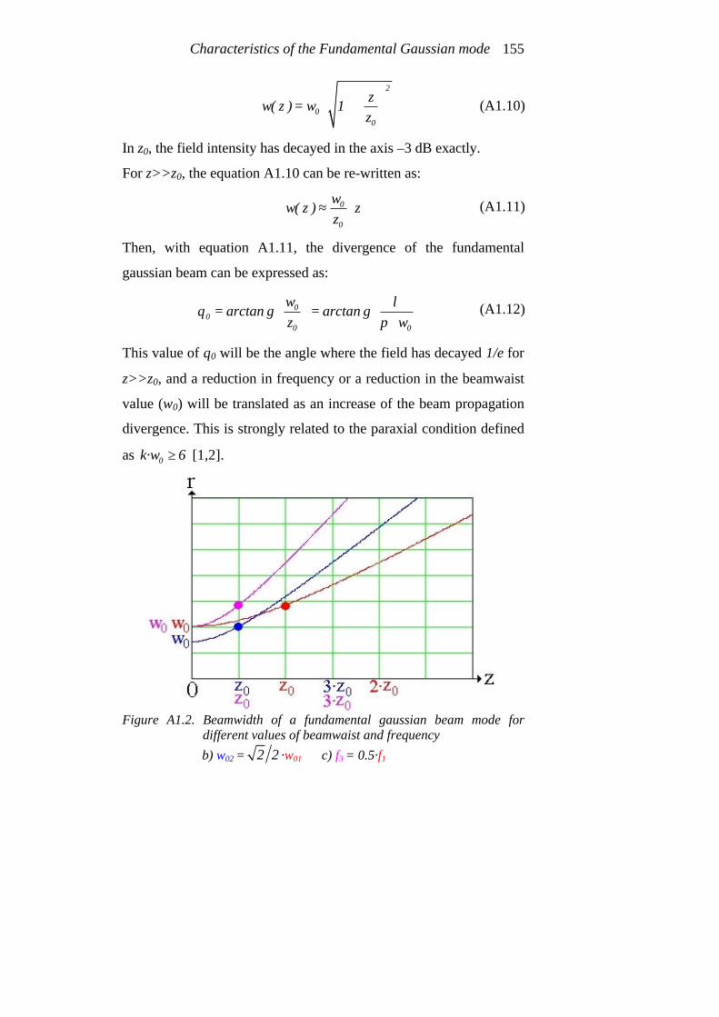
Characteristics of the Fundamental Gaussian mode 155
2
00
zw( z ) w 1
z
= ⋅ +
In z0, the field intensity has decayed in the axis –3 dB exactly.
For z>>z0, the equation A1.10 can be re-written as:
0
0
ww( z ) z
z≈ ⋅
Then, with equation A1.11, the divergence of the fundamental
gaussian beam can be expressed as:
00
0 0
warctan g arctan g
z wλ
θπ
= = ⋅
This value of θ0 will be the angle where the field has decayed 1/e for
z>>z0, and a reduction in frequency or a reduction in the beamwaist
value (w0) will be translated as an increase of the beam propagation
divergence. This is strongly related to the paraxial condition defined
as 0k·w 6≥ [1,2].
Figure A1.2. Beamwidth of a fundamental gaussian beam mode for
different values of beamwaist and frequency b) w02 = 2 2 ·w01 c) f3 = 0.5·f1
(A1.10)
(A1.11)
(A1.12)

Modern Corrugated Horn Antennas 156
• R(z) is defined as the wavefront radius of curvature. It is defined in
the following equation:
20z
R( z ) z 1z
= ⋅ +
In figure A1.3 it is depicted the variation of R(z). It can be extracted
from the figure that R(z) decreases from planar wave fronts at the
beamwaist ( R( z ) = ∞ ) to its minimum value at z0.
Figure A1.3. Fundamental gaussian beam wavefronts radius of curvature
• From equation A1.7 it is also defined ζ(z) as a little delay respect to
the planar wavefronts. It is expressed in equation A1.14 as:
0
z( z ) arctan g
zζ
=
Last equations define the propagation of a fundamental gaussian beam.
Then, any fundamental gaussian beam can be completely defined by the
beamwidth (w(z)) and the wavefront curvature radius (R(z)) in any place of
the free space. Once we know those two parameters and with the use of
equations A1.10 and A1.13 we can calculate the value for the beamwaist
(A1.13)
(A1.14)

Characteristics of the Fundamental Gaussian mode 157
(w0) and its position in the z axis. With w0 and its position we can easily
define completely the fundamental gaussian beam.
A1.2.2 Field intensity and carried power of a fundamental gaussian
beam mode
The field intensity of a fundamental gaussian beam mode is defined as
the squared modulus of the scalar field, (equation A1.7). Its equation can be
expressed as: 2
2
2 2 rw ( z )0
0
wI( r , ,z ) I e
w( z )ϕ
⋅−
= ⋅ ⋅
In figure A1.4, the fundamental gaussian field intensity in any place of
the propagating axis z is depicted.
Figure A1.4. Fundamental gaussian beam field intensity in any point of the z axis
a) Lateral view b) Top view
A particularization of equation A1.15 in the axis (r=0), we obtain
equation A1.16: 2
0 00 2
0
w II(0, ,z ) I
w( z ) z1
z
ϕ
= ⋅ =
+
(A1.15)
(A1.16)

Modern Corrugated Horn Antennas 158
From equation A1.16, at z=z0, the field intensity in the z axis is half of
the initial value at the beamwaist (I0).
In figure A1.5 is depicted the normalized field intensity, it can be
appreciated how the beam propagating in z axis diminishes its field intensity
and broadens itself.
Figure A1.5. Fundamental gaussian beam normalized field intensity for three
different points in the z axis
In figure A1.6 it is also depicted the normalized field intensity, but
now the r axis is fixed at r=0. It can be observed that a z=z0, the field
intensity decay is half of its value at the beamwaist (z=0).
Figure A1.6. Fundamental gaussian beam normalized field intensity for over the
axis r=0

Characteristics of the Fundamental Gaussian mode 159
In figure A1.7, a 3D view of figures A1.5 and A1.6 is depicted. This
figure clarifies the way a fundamental gaussian beam propagates in free
space.
Figure A1.7. Three dimensional distribution of the fundamental gaussian beam
normalized field intensity a) Lateral view b) Top view
The power that carries a fundamental gaussian beam can be calculated
by means of a field intensity integral over a surface, see equation A1.17: 2
0 0
P I( r , ,z ) r dr dπ
ϕ ϕ⋅ ∞
= ⋅∫ ∫
The fundamental gaussian beam has azimuthal symmetry, so the
previous integral equation can be simplified, (see equation A1.18):
0
P 2 I( r , ,z ) r drπ ϕ∞
= ⋅ ⋅ ⋅∫
Integrating equation A1.18 for a certain z, the carried power of a
fundamental gaussian beam results to be (equation A1.19):
( )20 0
1P I w
2π= ⋅ ⋅ ⋅
(A1.18)
(A1.19)
(A1.17)

Modern Corrugated Horn Antennas 160
Then, the power carried by a fundamental gaussian beam is half of the
intensity multiplied by the effective area of the beam defined by the radius
w0.
The relation between the power in a circle of radius r0 in a transversal
plane at a certain z position, and the total carried power by the beam can be
calculated by means of equation A1.20: 2
0022 rr
w ( z )
0
1I( r , ,z ) 2 r dr 1 e
Pϕ π
⋅−
⋅ ⋅ ⋅ ⋅ = −∫
Then, the power in a circle of radius r0=w(z) is approximately an
86.5% of the total power, and in a radius of r0=1.5·w(z) it is concentrated a
98.9% of the total power carried by the beam.
A1.2.3 Phase fronts of a fundamental gaussian beam mode
The phase of a fundamental gaussian beam mode can be extracted
from equation A1.7, (see equation A1.21): 2k r
arg( u( r , ,z )) k z ( z )2 R( z )
ϕ ζ⋅
= ⋅ − +⋅
We seek to obtain the expression for surfaces of constant phase, so
equation A1.21 can be made equal to a constant 2·π·q and then we obtain
the following equation: 2k r
2 q k z ( z )2 R( z )
π ζ⋅
⋅ ⋅ = ⋅ − +⋅
Equation A1.22 provides the 3D constant phase surfaces with a phase
of a value 2·π·q.
(A1.20)
(A1.22)
(A1.21)

Characteristics of the Fundamental Gaussian mode 161
In the following paragraphs, the approximated behaviour of the phase
fronts evolution is explained, [2]:
• When z 0→ , equation A1.22 can be simplified as: 2
20
k r2 q z
2 zπ
⋅⋅ ⋅ = ⋅
⋅
where the approximation 20R( z ) z z≈ has been considered.
Equation A1.23 provides an asymptotic behaviour when r → ∞ defining
a planar phase front.
• When z → ∞ , equation A1.22 can be simplified assuming R( z ) z≈
and ( z ) 2ζ π≈ resulting in:
2k r2 q k z
2 2 zπ
π⋅
⋅ ⋅ = ⋅ − +⋅
Equation A1.24 is the equation of an ellipse with a minor diameter
of 2·zc and a mayor diameter of c2 2 z⋅ ⋅ . The diameters crosspoint
is (r,z)=(0,zc). The formula of this ellipse is then defined in equation
A1.25:
( )2
2 2c c
rz z z
2 + − =
where zc is:
c
1q
4z2
λ ⋅ + =
The last approximations are depicted in figure A1.8 with a real picture
of the phase fronts. The approximation can be validated by means of such
figure.
(A1.23)
(A1.24)
(A1.25)
(A1.26)

Modern Corrugated Horn Antennas 162
Figure A1.8. Phase front representation of the fundamental gaussian beam
a) Approximated phase fronts b) Real phase fronts
The phase fronts are also depicted in figure A1.9 within the
propagation of the fundamental gaussian beam mode restricted to the region
that carries the 86.5% of the power (r<w(z)). Figure A1.9 shows that very
near the beamwaist the phase fronts are nearly planar and for far away the
beamwaist the phase fronts can be approximated by spheres.
Figure A1.9. Phase front representation of the fundamental gaussian beam
restricted to r<w(z)

Characteristics of the Fundamental Gaussian mode 163
A1.3 References
[1] del Río, C., Gonzalo, R. and Sorolla, M., “Paraxiality Considerations of
Higher Order Gaussian Modes”, International Conference on Infrared
and Millimeter Waves. Year 1996. AT11, Conf. Proceedings,
ISBN: 3-00-000800-4
[2] del Río, C., “Diseño de Guías de Onda Cuasi-Ópticas para Modos
Gaussianos de Orden Superior”, Ph. D dissertation, Electric and
Electronic Engineering Department, Public University of Navarra. Year
1996.

Modern Corrugated Horn Antennas 164
Appendix II
Resonance spikes in corrugated horn
antennas
A theoretical study reinforced with practical measurements about the
origin of the return loss spikes in corrugated horn antennas is covered in
this appendix. These spikes are directly related to the periodic structure of
the corrugations and can be evaluated in simulation and sometimes in
measurements. In this appendix we try to explain their effects, their origin
and also several techniques to avoid them.
A2.1 Origin of the resonance spikes
Every corrugated horn antenna presents at a certain frequency band
some resonance spikes. To characterize these spikes we will use the conical
corrugated horn antenna model for X band of figure A2.1. This antenna
presented this type of resonance spikes in the middle of its bandwidth (11.6
to 12.2 GHz), see figure A2.2. Its corrugation parameters are p=3.4 mm,
w=0.9 mm and d=5.9 mm. It presents also an impedance transformer
between λ/2 to λ/4 corrugation depth at the throat (see figure A2.1).
Corrugated horn antennas, due to the periodic structure of its
corrugations (with ideally completely straight walls) can be considered as
the concatenation of a series of small resonators.

Modern Corrugated Horn Antennas 166
Figure A2.1. Conical corrugated horn antenna profile
This resonators will produce certain reflections at certain frequencies
due to the collision of the electromagnetic field against this corrugations,
(see figure A2.2). The most likely place to receive such a collision is just
where the impedance transformer finishes and this happens due to two
principal reasons:
- Corrugation depth is λ/4
- The diameter of the horn is reduced, so there is a quite big amount of
electromagnetic fields very near the corrugations.
A resonance implies a high diffraction of the electromagnetic field
travelling inside the corrugated horn (a big field intensity inside the
corrugation). This electromagnetic field diffraction at the throat is strongly
related with the input diameter of the horn antenna, if the input diameter is
small, (below 0.7·λ), the diffraction will be big. Usually we select an input
diameter of 0.78·λ, but the operating band of an antenna produces at low
frequencies to have the electromagnetic field at the input diameter of the
horn antenna slightly tight. If the relation between the corrugation period,
(p), the corrugation tooth width, (w) and the wavelength of every mode in

Resonance spikes in corrugated horn antennas 167
the corrugated region (λg) are an exact multiple of λg/2, then we will have a
lot of possibilities of having a resonance inside our corrugated horn antenna.
Figure A2.2. Electric field intensity inside the conical corrugated horn antenna at
two frequencies a) Without resonance b) With resonance c) Return loss detail of the antenna
A2.2 How to eliminate the resonance spikes
To suppress the resonance spikes in a corrugated horn antenna there
are several methods:

Modern Corrugated Horn Antennas 168
- An increase in the corrugation period of the antenna lowers the
resonance spikes to lower frequencies. Figure A2.3 shows the effect of
using a corrugation period of 4.5 mm instead of 3.4 mm for the antenna.
No resonance spikes and the radiation parameters remain unchanged,
now 5p λ≈ .
Figure A2.3. a) Return loss, p=4.5 mm and w=1.5 mm
b) Directivity comparison c) Maximum crosspolar level comparison d) Sidelobe and shoulder level comparison
- A change in the corrugation depth for the antenna will change the
resonating frequency of each little resonator. Using a corrugation depth
of 6.6 mm instead of the 5.9 mm of the last figures the resonance spikes
move to lower frequencies and in the radiating properties, only the

Resonance spikes in corrugated horn antennas 169
crosspolar pattern changes, in this case changes to better response, (see
figure A2.4).
Figure A2.4. a) Return loss, d=6.6 mm
b) Directivity comparison c) Maximum crosspolar level comparison d) Sidelobe and shoulder level comparison
- Another way of reducing the resonance spikes is affecting to the purity
of the resonators (corrugations). In a manufactured antenna, the
corrugation walls will never be completely straight. Because of that the
resonance spikes will have a finite quality factor (Q). A slight slope in
the corrugations manufacture process will be welcome in case annoying
spikes result impossible to remove in the simulation process, (see figure
A2.5).

Modern Corrugated Horn Antennas 170
Figure A2.5. a) Detail of an exaggerated slope of the corrugations
b) Return loss for the antenna with a corrugation slope of 0.2 degrees
A2.3 References [1] Arun K. Bhattacharyya, “High-Q resonances due to surface waves and
their effects on the performances of corrugated horns”, IEEE
Transactions on Antennas and Propagation, vol. 49, n. 4, pp. 555-566,
April 2001
[2] Teniente-Vallinas, J., Gonzalo-García, R. and del-Río-Bocio, C., “Ultra-
Wide Band Corrugated Gaussian Profiled Horn Antenna Design”, 2001
IEEE AP-S International Symposium and USNC/URSI National Radio
Science Meeting, 8-13 of July, Boston, Massachusetts, United States of
America
[3] Teniente-Vallinas, J., Gonzalo-García, R. and del-Río-Bocio, “Estudio
de Resonancias Parásitas en Antenas Corrugadas”, XVI Symposium de la
Unión Científica Internacional de Radio (URSI’01). Villaviciosa de
Odón, (Madrid), September 2001
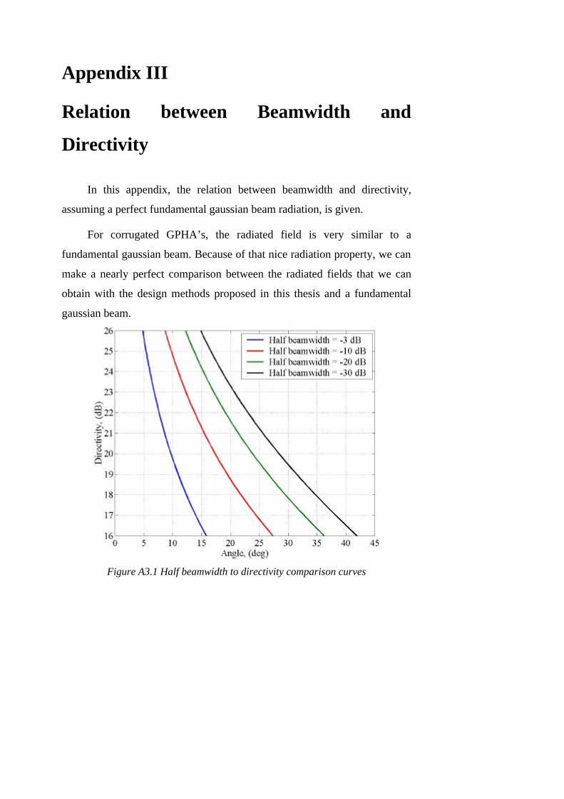
Appendix III
Relation between Beamwidth and
Directivity
In this appendix, the relation between beamwidth and directivity,
assuming a perfect fundamental gaussian beam radiation, is given.
For corrugated GPHA’s, the radiated field is very similar to a
fundamental gaussian beam. Because of that nice radiation property, we can
make a nearly perfect comparison between the radiated fields that we can
obtain with the design methods proposed in this thesis and a fundamental
gaussian beam.
Figure A3.1 Half beamwidth to directivity comparison curves

Modern Corrugated Horn Antennas 172
To aid the designers that work on beamwidth values to define the
radiation pattern of a corrugated GPHA, in the following figures this
directivity to different beamwidth values can be found. In figure A3.1 a
comparison between 4 different half beamwidths is given. Figure A3.2 gives
a clearer plot for each of the four beamwidths of figure A3.1.
Figure A3.2 Half beamwidth to directivity comparison (detailed plots)
a) Half beamwidth –3 dB b) Half beamwidth –10 dB c) Half beamwidth –20 dB d) Half beamwidth –30 dB
List of Publications
Related to the Thesis
Patents
1. Gonzalo, R., del Río, C., Goñi, D. and Teniente, J. “Antena de bocina
que combina corrugaciones horizontales y verticales” Number: P.2002
01264. Priority country: Spain. Priority date: 24-05-2002 PCT initiated:
17-05-2003 Property of: Public University of Navarra (U.P.N.A.)
Journals
1. Teniente, J., Goñi, D., Gonzalo, R. and del Río, C. “Choked Gaussian
Antenna: Extremely Low Sidelobe Compact Antenna Design”, IEEE
Antennas and Wireless Propagation Letters, Vol. 1, N. 11, pp. 200-202,
November 2002
2. Gonzalo, R., Teniente, J., del Río, C. “Improved Radiation Pattern
Performance of Gaussian Profiled Horn Antennas”, IEEE Transactions
on Antennas and Propagation, Vol. 50, N. 11, pp. 1505-1513, November
2002
3. Teniente, J., Gonzalo, R., del Río, C. “Ultra Wide Band Corrugated
Gaussian Profiled Horn Antenna Design”, IEEE Microwave and Wireless
Components Letters, Vol. 12, No. 1, pp. 20-21. January 2002
4. Teniente, J., Gonzalo, R., del Río, C. “Gaussian Profiled Horn Antenna
for Hispasat 1C Satellite”, International Journal of Infrared and
millimeter Waves, Vol. 20, No. 10, pp. 1809-1815, October 1999

Modern Corrugated Horn Antennas 174
5. Teniente, J., Gonzalo, R., del Río, C., Martí-Canales, J., Sorolla, M.,
Fernández, A., Likin, K. M. and Martín, R. “Corrugated Horn Antenna
for Low-Power Testing of the Quasioptical Transmission lines at TJ-II
Stellerator”, International Journal of Infrared and millimeter Waves,
Vol. 20, No. 10, pp. 1757-1767, October 1999
International conferences
1. Teniente, J., Gonzalo, R., del Río, C. “Modern Corrugated Horn
Antenna Design for Extremely Low Sidelobe Level “ Poster
presentation at the 26th ESA Antenna Technology Workshop on Satellite
Antenna Modelling and Design Tools, 12-14 November 2003,
ESA/ESTEC, Noordwijk, Holland
2. Teniente, J., Ortiz, N., Gonzalo, R., del Río, C. “Choked-Gaussian
Corrugated Horn Antenna Design Small Global Coverage Horn Antenna
for TT&C with Extremely Low Sidelobe Level“ Poster presentation at
the 26th ESA Antenna Technology Workshop on Satellite Antenna
Modelling and Design Tools, 12-14 November 2003, ESA/ESTEC,
Noordwijk, Holland
3. Teniente, J., Gonzalo, R., del Río, C. “Conical versus gaussian profiled
corrugated horn antennas”, 2002 IEEE AP-S International Symposium
and USNC/URSI National Radio Science Meeting, 16-21 of June, San
Antonio, Texas, United States of America
4. Teniente, J., Gonzalo, R., del Río, C. “Ultra-Wide Band Corrugated
Gaussian Profiled Horn Antenna Design”, 2001 IEEE AP-S
International Symposium and USNC/URSI National Radio Science
List of Publications 175
Meeting, 8-13 ofe July, Boston, Massachusetts, United States of
America
5. Teniente, J., Gonzalo, R., del Río, C. “Gaussian Profiled Horn
Antennas”, ISRAMT’99 7th International Symposium on Recent Advances
in Microwave Technology. Malaga, Spain December 1999.
6. Fernandez Curto, A., Likin, K. M., Martín, R., Martí Canales, J.,
Teniente, J., Gonzalo, R., del Río, C. and Sorolla, M. “Corrugated Horn
Antenna for Low-Power testing of the Quasioptical Transmission Lines
at TJ-II Stellerator”, AMTA’99 21st Annual Meeting and Symposium on
Antenna Measurement Techniques Association. Monterey Bay,
California, United States of America. October 1999
7. Teniente, J., Gonzalo, R., Sorolla, M. and del Río, C. “Generation of the
HE11 mode in Rectangular Waveguide Using Gaussian Techniques”,
1999 IEEE AP-S International Symposium and URSI Radio Science
Meeting, 11-15 of July, Orlando, Florida, United States of America
8. Gonzalo, R., Martí-Canales, J., Teniente, J., del Río, C. and Sorolla, M.
“Measurements of a New Gaussian Profile Corrugated Horn Antenna for
Millimeter Wave Applications”, 1998 IEEE AP-S International
Symposium and URSI Radio Science Meeting, 21-26 of June, Atlanta,
Georgia, United States of America
9. del Río, C., Teniente, J., Gonzalo, R., and Sorolla, M. “On the
Determination of the Phase Center of Gaussian Horn Antennas”, 2nd ESA
Workshop on Millimetre Wave Technology and Applications, 27-29 of
May 1998, Millilab, Espoo, Finland

Modern Corrugated Horn Antennas 176
10. Teniente, J., Gonzalo, R. and del Río, C. “A novel and Efficient
Corrugated Feeder for Reflector Antennas”, 1997 IEEE AP-S
International Symposium and URSI Radio Science Meeting, 14-18 of
July, Montreal, Canada
11. Gonzalo, R., Teniente, J. and del Río, C., “Very Short and Efficient
Feeder Design from Monomode Waveguide”, 1997 IEEE AP-S
International Symposium and URSI Radio Science Meeting, 14-18 of
July, Montreal, Canada
12. Gonzalo, R., Teniente, J., del Río, C. and Sorolla, M. “New Approach to
the Design of Corrugated Horn Antennas”, 20th ESTEC Antenna
Workshop on Millimetre Wave Antenna Technology and Antenna
Measurements, 18-20 of June 1997, Noordwijk, Holland
13. Gonzalo, R., del Río, C., Teniente, J. and Sorolla, M “Optimal horn
antenna design to excite high purity gaussian beam using overmoded
waveguides”, XXI Int. Conf. on Infrared and Millimeter Waves. Berlin,
Germany, July 1996
National conferences
1. Ortiz, N., Teniente, J., Gonzalo, R. and del Río, C., “Diseño de una
antena dual gaussiana de doble profundidad de corrugación” XVIII
Symposium de la Unión Científica Internacional de Radio (URSI’03). La
Coruña, Spain, September 2003
2. Teniente, J., Gonzalo, R. and del Río, C., “Comparación Entre Antenas
Cónicas Corrugadas y Antenas Gaussianas Corrugadas” XVII Symposium
de la Unión Científica Internacional de Radio (URSI’02). Alcalá de
Henares, Madrid, Spain, September 2002

List of Publications 177
3. Goñi, D., Teniente, J., Gonzalo, R. and del Río, C., “Diseño y Medida de
una Antena Choke-Gaussiana” XVII Symposium de la Unión Científica
Internacional de Radio (URSI’02). Alcalá de Henares, Madrid, Spain,
September 2002
4. Teniente, J., Gonzalo, R. and del Río, C., “Antena Corrugada con Perfil
Gaussiano de Gran Ancho de Banda” XVI Symposium de la Unión
Científica Internacional de Radio (URSI’01). Villaviciosa de Odón,
Madrid, Spain, September 2001
5. Teniente, J., Gonzalo, R. and del Río, C., “Estudio de Resonancias
Parásitas en Antenas Corrugadas” XVI Symposium de la Unión
Científica Internacional de Radio (URSI’01). Villaviciosa de Odón,
Madrid, Spain, September 2001.
6. Teniente, J., Gonzalo, R. and del Río, C., “Alimentadores Gaussianos en
Guía de Onda Rectangular” XIV Symposium de la Unión Científica
Internacional de Radio (URSI’99). Santiago de Compostela, Spain,
September 1999
7. Fernandez, A., Likin, K. M., Teniente, J., Turullols, P., Gonzalo, R., del
Río, C., Sorolla, M. and Martín, R. “Líneas de Transmisión Cuasi-
ópticas en el Stellerator TJ-II” Poster presentation XIII Symposium de la
Unión Científica Internacional de Radio (URSI’98). Pamplona, Spain,
September 1998
8. Teniente, J., Turullols, P., del Río, C. and Sorolla, M. “Fórmulas de
Referencia Normalizadas para Propagación y Radiación en Guía
Rectangular” Poster presentation XIII Symposium de la Unión Científica
Internacional de Radio (URSI’98). Pamplona, September 1998

Modern Corrugated Horn Antennas 178
9. Gonzalo, R. and del Río, C., Teniente, J. and Sorolla, M. “Diseño óptimo
de antenas de bocina multimodo para excitar un haz gaussiano
fundamental de alta pureza” XI Symposium de la Unión Científica
Internacional de Radio (URSI’96). Madrid, Spain, September 1996
10. Gonzalo, R. and del Río, C., Teniente, J. and Sorolla, M. “Generación
del modo HE11 a partir de una guía circular lisa monomodo” XI
Symposium de la Unión Científica Internacional de Radio (URSI’96).
Madrid, Spain, September 1996
Epilogue
El hombre no tejió la trama de la vida;
él sólo es un hilo
Lo que hace con la trama se lo hace a sí mismo