modem 2400 90239 - stevens water environmental modem 2400 specifications 2 ... where the modulator...
TRANSCRIPT

Stevens® Environmental Modem 2400
INSTRUCTION 90239A JULY 1994


i 90239A
Table of Contents _____________________________________________________________
1. INTRODUCTION 1 1.1 GENERAL DESCRIPTION 1 1.2 SAFETY INFORMATION 2 1.3 ENVIRONMENTAL MODEM 2400 SPECIFICATIONS 2 1.4 FCC CUSTOMER INFORMATION 4 2. INSTALLATION 5 2.1 INTRODUCTION 5 2.2 CONNECTION TO A STEVENS LOGGER 5 2.3 SPECIAL POWER OPTION 6 2.4 CONNECTION TO THE TELEPHONE LINE 6 2.5 SURGE PROTECTION RECOMMENDATIONS 6 3. OPERATION 8 3.1 INTRODUCTION 8 3.2 OPERATION AS A "BASIC" MODEM 8 3.3 OPERATION AS A "SMART" MODEM 9 4. MAINTENANCE 10 4.1 GENERAL INFORMATION 10 4.2 FACTORY SERVICE 10 5. TROUBLESHOOTING 11 5.1 GENERAL INFORMATION 11 5.2 TROUBLESHOOTING TABLE 11 6. APPENDICES 12 6.1 CONFIGURATION PROFILES AND S-REGISTERS 12 6.2 OPERATING MODES 15 6.3 COMMAND MODE - AT COMMANDS 16 ILLUSTRATIONS Figure 1 Environmental Modem 2400 1 Figure 2 System Configuration 2 Figure 3 Rear Panel 5 Figure 4 Communications Cables, Stevens Loggers 25 TABLES Table 1 Communications Connector Pinouts 5 Table 2 Auxiliary Power Connector Pinouts 6 Table 3 AT Immediate Commands 17 Table 4 AT Set Commands 19 Table 5 S-Registers 23
ii 90239A
Safety and Equipment Protection
_____________________________________________________________ WARNING! ELECTRICAL POWER CAN RESULT IN DEATH, PERSONAL INJURY OR CAN CAUSE DAMAGE TO EQUIPMENT. If the instrument is driven by an external power source, disconnect the instrument from that power source before attempting any repairs. WARNING! BATTERIES ARE DANGEROUS. IF HANDLED IMPROPERLY, THEY CAN RESULT IN DEATH, PERSONAL INJURY OR CAN CAUSE DAMAGE TO EQUIPMENT. Batteries can be hazardous when misused, mishandled, or disposed of improperly. Batteries contain potential energy, even when partially discharged. WARNING! ELECTRICAL SHOCK CAN RESULT IN DEATH OR PERSONAL INJURY. Use extreme caution when handling cables, connectors, or terminals; they may yield hazardous currents if inadvertently brought into contact with conductive materials, including water and the human body. CAUTION! Be aware of protective measures against environmentally caused electric current surges. Read the Stevens Engineering Applications Note, Surge Protection of Electronic Circuits, publication number 42147. In addition to the previous warnings and cautions, the following safety activities should be carefully observed.
iii 90239A
Safety and Equipment Protection _____________________________________________________________
Children, Adolescents NEVER give batteries to young people who may not be aware of the hazards associated with batteries and their improper use or disposal. Jewelry, Watches, Metal Tags To avoid severe burns, NEVER wear rings, necklaces, metal watch bands, bracelets, or metal identification tags near exposed battery terminals. Heat, Fire NEVER dispose of batteries in fire or locate them in excessively heated spaces. Observe the temperature limit listed in the instrument specifi-cations. Charging NEVER charge "dry" cells or lithium batteries that are not designed to be charged. NEVER charge rechargeable batteries at currents higher than recom-mended ratings. NEVER recharge a frozen battery. Thaw it completely at room temperature before connecting charger. Unvented Container NEVER store or charge batteries in a gas-tight container. Doing so may lead to pressure buildup and explosive concentrations of hydrogen. Short circuits NEVER short circuit batteries. High current flow may cause internal battery heating and/or explosion.

iv 90239A
Safety and Equipment Protection _____________________________________________________________
Damaged Batteries Personal injury may result from contact with hazardous materials from a damaged or open battery. NEVER attempt to open a battery enclosure. Wear appropriate protective clothing, and handle damaged batteries carefully. Disposal ALWAYS dispose of batteries in a responsible manner. Observe all applicable federal, state, and local regulations for disposal of the specific type of battery involved.
NOTICE Stevens makes no claims as to the immunity of its equipment against lightning strikes, either direct or nearby. The following statement is required by the Federal Communications Commission: WARNING - This equipment generates, uses, and can radiate radio frequency energy, and, if not installed in accordance with the instructions manual, may cause interference to radio communications. It has been tested and found to comply with the limits for a Class A computing device pursuant to Subpart J of Part 15 of FCC Rules, which are designed to provide reasonable protection against such interference when operated in a commercial environment. Operation of this equipment in a residential area is likely to cause interference in which case the user at his own expense will be required to take whatever measures may be required to correct the interference.
USER INFORMATION
Stevens makes no warranty as to the information furnished in these instructions and the reader assumes all risk in the use thereof. No liability is assumed for damages resulting from the use of these instructions. We reserve the right to make changes to products and/or publications without prior notice.

1 Introduction_____________________________________________________________
1 90239A
Figure 1 The Stevens® Environmental Modem 2400 1.1 GENERAL INFORMATION The Stevens® Environemtal Modem 2400 (Figure 1) is designed to provide a means of transferring data over the public switched telephone network from Stevens field equipment to a central office location. Engineered for use in a sheltered enclosure, the Modem operates from -40 to +185°F (-40 to +85°C) and the circuit board is conformally coated to reduce the effects of humidity. The Modem features automatic speed selection from 300 to 2400 bits per second and will respond to the popular AT Command set. To transmit data over the telephone line, the equipment at each end must have a modem connected between the equipment and the telephone line. The modem at the transmitting end converts the digital signals to analog signals, suitable for transmission over the telephone line. The modem at the receiving end reverses the process, to recreate the digital signal. The word "modem" is short for modulator-demodulator, where the modulator converts digital to analog signals, for transmission through the telephone network, and the demodulator converts the analog signals back to digital. Once the telephone connection is established, the field equipment can communicate as if directly connected to the computer. The Modem is designed for connection to RS-232 compatible devices, and receives power from a 12 volt, direct-current source. Power is normally supplied through the data connector from a Stevens Logger, but the Modem can also be connected to an independent 12 volt supply. The Modem only requires substantial power when the associated Logger or data equipment is active, and remains idle at very low current for the rest of the time. A typical remote logging system is shown in Figure 2, System Configuration. This instruction is organized in Sections as follows: 1 Introduction, 2 Installation, 3 Operation, 4 Maintenance, 5 Troubleshooting and 6 Appendices.

1 Introduction_____________________________________________________________
2 90239A
Figure 2 System Configuration 1.2 SAFETY INFORMATION Before performing any procedure in this manual, please read all applicable warnings and cautions. 1.3 ENVIRONMENTAL MODEM 2400 SPECIFICATION Compatibility: V.22bis/V.22/V.21, Bell 212A/103 Operation: Full-duplex on 2-wire dial-up line Data Rates: 2400, 1200, 300 bits per second Modulation: High Speed - QAM (Quadrature amplitude modulation) Medium Speed - DPSK (diffentially coherent phase shift keying) Low Speed - FSK (frequency shift keying) Control: AT command interpreter Transmitter Output: -11.5 dBm minimum Receive
RJ-11 TELEPHONE JACK
BATTERY
LOGGER MODEM

1 Introduction_____________________________________________________________
3 90239A
Dynamic Range: -3 to -43 dBm Interface: RS-232: TXD, RXD, DCD, DSR, CTS, RTS, DTR, RI Line Impedance: 600 ohm, transformer coupled Line Protection: IEEE 472 Lightning and Transient Protection User Configuration: Non-volatile EEPROM to store user configuration Handshake: Automatic as defined by V.22bis/V.22 and Bell 212A/103 Equalization: Adaptive equalization with auto-retrain Dialer Type: DTMF or Pulse Power Mode: Switched power or constant power (jumper selection) Input Voltage 5 to 15 volts, direct current; active current: 75 mA Range: typical Standby Current: 50 µA typical (switched low-power mode only) Environment: -40 to +185 ° F (-40 to +85° C), 0 - 95% relative humidity, non-condensing Certification: FCC Part 68 and Part 15 Construction: Conformally-coated epoxy-glass circuit board housed in a sturdy aluminum enclosure Size: 1.62 in. high x 7.29 in. wide x 5.20 in. deep (41.1 x 185 x 132 mm) Weight: 1.1 lb. (0.5 kg)

1 Introduction_____________________________________________________________
4 90239A
1.4 FCC CUSTOMER INFORMATION The Modem complies with Part 68 of the Federal Communications Commis-sion (FCC) Rules. The FCC identification label, mounted beneath the enclo-sure, includes the FCC Registration Number 1V9USA-74507-DT-E and the Ringer Equivalence Number (REN) 0.4B for the modem. If requested, this information must be provided to the telephone company. The REN is used to determine the quantity of devices which may be connec-ted to the telephone line. Excessive REN's on the telephone line may result in the devices not ringing in response to an incoming call. In most, but not all areas, the sum of the REN's should not exceed five (5.0). To be certain of the number of devices that may be connected to the telephone line, deter-mined by the total REN's, contact the telephone company to verify the maxi-mum REN for the calling area. The Modem requires a RJ11C registered USOC jack. Jacks of this type of equipment are not to be provided on party or coin-service lines. If trouble is experienced with the Modem, disconnect the Modem from the telephone line until the problem is determined and repaired. Contact a Stevens Technical Representative, (800-452-5272), for repair or warranty information. If the Modem causes harm to the telephone network, the tele-phone company may request the Modem be disconnected from the network until the problem is resolved. If the Modem causes harm to the telephone network, the telephone com-pany will notify you in advance that temporary discontinuance of service may be required. If advance notice is not practical, the telephone company will notify the customer as soon as possible. You will be advised of your right to file a complaint with the FCC if you believe it is necessary. The telephone company may make changes in its facilities, equipment, operations, or procedures that could affect the operation of the Modem. If this happens, the telephone company will provide advance notice for you to make the necessary modifications to maintain uninterrupted service.
2 Installation_____________________________________________________________
5 90239A
2.1 INTRODUCTION Unpack the Modem and inspect it for any shipping damage. If there is any apparent damage, contact the shipping agency for their recommendations. Also contact Stevens for replacement of the unit. Install the Modem in a weather-sheltered enclosure. Position the unit so the data and telephone cables will reach the associated Logger and telephone jack, respectively. 2.2 CONNECTION TO A STEVENS LOGGER
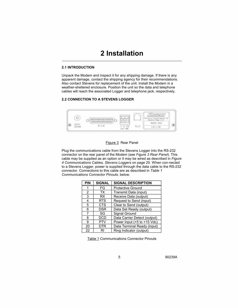
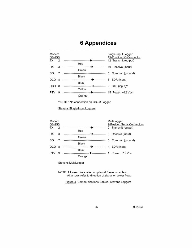
Figure 3 Rear Panel Plug the communications cable from the Stevens Logger into the RS-232 connector on the rear panel of the Modem (see Figure 3 Rear Panel). This cable may be supplied as an option or it may be wired as described in Figure 4 Communications Cables, Stevens Loggers on page 25. When con-nected to a Stevens Logger, power is supplied through the data cable to the RS-232 connector. Connections to this cable are as described in Table 1 Communications Connector Pinouts, below.
PIN SIGNAL SIGNAL DESCRIPTION 1 FG Protective Ground 2 TX Transmit Data (input) 3 RX Receive Data (output) 4 RTS Request to Send (input) 5 CTS Clear to Send (output) 6 DSR Data Set Ready (output) 7 SG Signal Ground 8 DCD Data Carrier Detect (output) 9 PTV Power Input (+5 to +15 Vdc)
20 DTR Data Terminal Ready (input) 22 RI Ring Indicator (output)
Table 1 Communications Connector Pinouts
2 Installation_____________________________________________________________
6 90239A
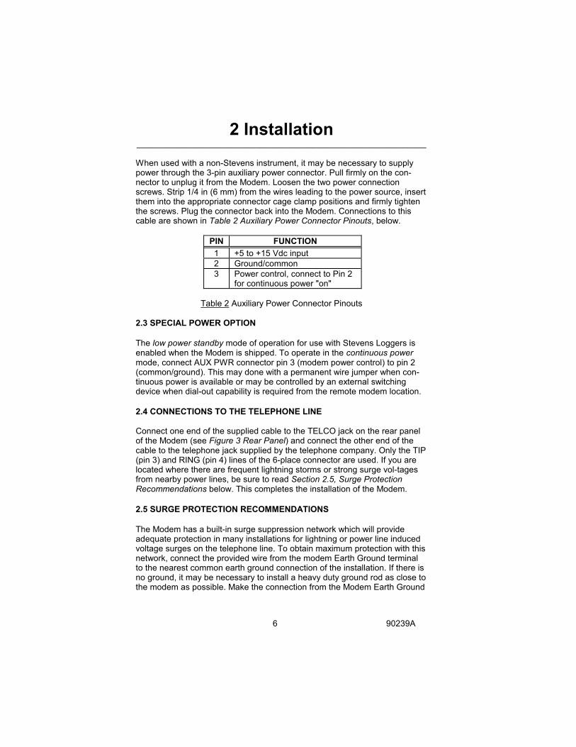
When used with a non-Stevens instrument, it may be necessary to supply power through the 3-pin auxiliary power connector. Pull firmly on the con-nector to unplug it from the Modem. Loosen the two power connection screws. Strip 1/4 in (6 mm) from the wires leading to the power source, insert them into the appropriate connector cage clamp positions and firmly tighten the screws. Plug the connector back into the Modem. Connections to this cable are shown in Table 2 Auxiliary Power Connector Pinouts, below.
PIN FUNCTION 1 +5 to +15 Vdc input 2 Ground/common 3 Power control, connect to Pin 2
for continuous power "on"
Table 2 Auxiliary Power Connector Pinouts 2.3 SPECIAL POWER OPTION The low power standby mode of operation for use with Stevens Loggers is enabled when the Modem is shipped. To operate in the continuous power mode, connect AUX PWR connector pin 3 (modem power control) to pin 2 (common/ground). This may done with a permanent wire jumper when con-tinuous power is available or may be controlled by an external switching device when dial-out capability is required from the remote modem location. 2.4 CONNECTIONS TO THE TELEPHONE LINE Connect one end of the supplied cable to the TELCO jack on the rear panel of the Modem (see Figure 3 Rear Panel) and connect the other end of the cable to the telephone jack supplied by the telephone company. Only the TIP (pin 3) and RING (pin 4) lines of the 6-place connector are used. If you are located where there are frequent lightning storms or strong surge vol-tages from nearby power lines, be sure to read Section 2.5, Surge Protection Recommendations below. This completes the installation of the Modem. 2.5 SURGE PROTECTION RECOMMENDATIONS The Modem has a built-in surge suppression network which will provide adequate protection in many installations for lightning or power line induced voltage surges on the telephone line. To obtain maximum protection with this network, connect the provided wire from the modem Earth Ground terminal to the nearest common earth ground connection of the installation. If there is no ground, it may be necessary to install a heavy duty ground rod as close to the modem as possible. Make the connection from the Modem Earth Ground

2 Installation_____________________________________________________________
7 90239A
terminal to the rod with as short and heavy a copper lead or braid as is practical. Make sure that the connections are tight. In severe storm areas where the equipment building is located in an exposed location, it may be necessary to obtain the services of a knowledgable local consultant. Drastic measures may be required to provide adequate protec-tion, such as a professionally-installed lightning rod and grounding system. The cost of adequate protection must be balanced against the cost of repla-cing damaged equipment and loss of data. If the Modem is powered by a supply connected to the power lines, an appropriately-rated suppressor is recommended between the line and the power supply. The ground lead for that suppressor should go to the same ground rod connection described above.
3 Operation_____________________________________________________________
8 90239A
3.1 INTRODUCTION The Stevens Environmental Modem 2400 will operate as a basic answer modem, as installed above. The central office location that acts as the cal-ling party must be equipped with a personal computer that has an internal modem or be connected to an external modem. The computer must be run-ning a terminal program, such as Stevens MODTERM, or in the "terminal", "local" or "dumb" mode of a commercial communications program. Set the program to 2400 baud, 7 data bits, 1 stop bit and even parity. Also set the computer for full duplex, ASCII file transfer protocol and TTY termi-nal emulation. Set the remote Logger or other instrument to the same baud rate and protocol as above. The modem that is connected to the personal computer must also support the program baud rate; if not, set the program, modem and Logger to the highest supported rate, either 1200 or 300 baud. When telephone line conditions are poor, the Modem will automatically ad-just the data communications (baud) rates to lower values, if necessary to establish reliable communications. Where good telephone line conditions exist, the modems will operate at the highest rate, with the fastest transfer of data and lowest telephone line charges. However, the Loggers operate at the switch-selected baud rate, and will not automatically fall back to a lower rate. User experience with a particular telephone line will indicate whether there are marginal conditions; it may be necessary to set all of the connec-ted equipment to a lower baud rate for reliable communications. 3.2 OPERATION AS A "BASIC" MODEM Communications programs differ in detail, so the actual command structure is not described here. Refer to the communications program user manual for details. However, all of the programs feature certain necessary operations: 1. Connect to the telephone line, 2. Dial the remote telephone number and connect to the remote modem, 3. Open a computer file for storage of remote data, 4. Communicate with the remote Logger, using the Logger commands to modify operation or request a data dump to a computer file, 5. Name and Save the computer file, generally to disk, 6. Disconnect from or "hang up" the telephone line. Follow the communications program user instructions to perform these basic operations to operate as a "basic" modem. 3.3 OPERATION AS A "SMART" MODEM

3 Operation_____________________________________________________________
9 90239A
Various commercially-available communications programs can be used with a computer to select special modem operations, such as auto-dialing and scripted languages which permit automated programming and polling of large networks. See their user instruction for details. The Modem itself supports the AT Commands, compatible with the extensive Hayes Smartmodem command set, which permits great flexibility in using your computer to tailor modem operation to your needs. The command set is not needed to retrieve data from Stevens loggers, but is presented as a reference in Section 6 Appendices for future use in remote autodialing systems, or when the Modem is purchased for use with a non-Stevens instrument or system.

4 Maintenance _____________________________________________________________
10 90239A
4.1 GENERAL INFORMATION The Modem should be located in a weather-resistant enclosure, in reason-ably dry and clean conditions. The Modem is designed to provide long, trouble-free service with no periodic maintenance. To ensure this level of performance, the following items should be checked on a regular basis: 1. Verify that there are no water leaks that can enter the equipment. 2. Check the battery or other power source voltage to the Modem and asso-ciated equipment at each visit to the site. Exchange rechargeable lead-acid batteries when their terminal voltage drops below 12.0 volts. The Modem will operate at much lower voltages, but poor voltage regulation from a dis-charged battery may cause data loss by the connected equipment. 3. Check power and signal connections for tightness and signs of corrosion; tighten or clean, as required. 4.2 FACTORY SERVICE If there is a problem with Modem operation, call and ask for a Stevens Cus-tomer Technical Representative. The direct dial number for Stevens is 1-800-452-5272, and the call is free from Canada or the USA. An alternative number is: 1-503-469-8000. Please provide an instrument description and serial number, when possible. Many questions can be answered by telephone, or you may obtain authorization for return of the Modem, should that be necessary. Modems must be repaired at a fac-tory-authorized facility with approved components, in order to maintain their FCC Certification and provide safe operation on the telephone system. The factory is open Monday through Friday from 7 a.m. to 5 p.m., in the Pacific Time Zone. If no one is available, you can leave a message at any time on an excellent phone mail system; just clearly tell us your name, location, tele-phone number and how to reach you. Service Record Notes:
5 Troubleshooting _____________________________________________________________
11 90239A
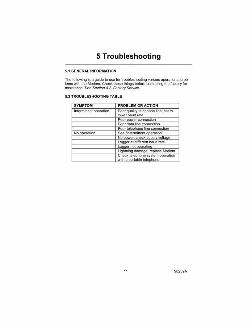
5.1 GENERAL INFORMATION The following is a guide to use for troubleshooting various operational prob-lems with the Modem. Check these things before contacting the factory for assistance. See Section 4.2, Factory Service. 5.2 TROUBLESHOOTING TABLE
SYMPTOM PROBLEM OR ACTION Intermittent operation Poor quality telephone line; set to
lower baud rate Poor power connection Poor data line connection Poor telephone line connection No operation See "intermittent operation" No power; check supply voltage Logger at different baud rate Logger not operating Lightning damage, replace Modem Check telephone system operation
with a portable telephone
6 Appendices _____________________________________________________________
12 90239A
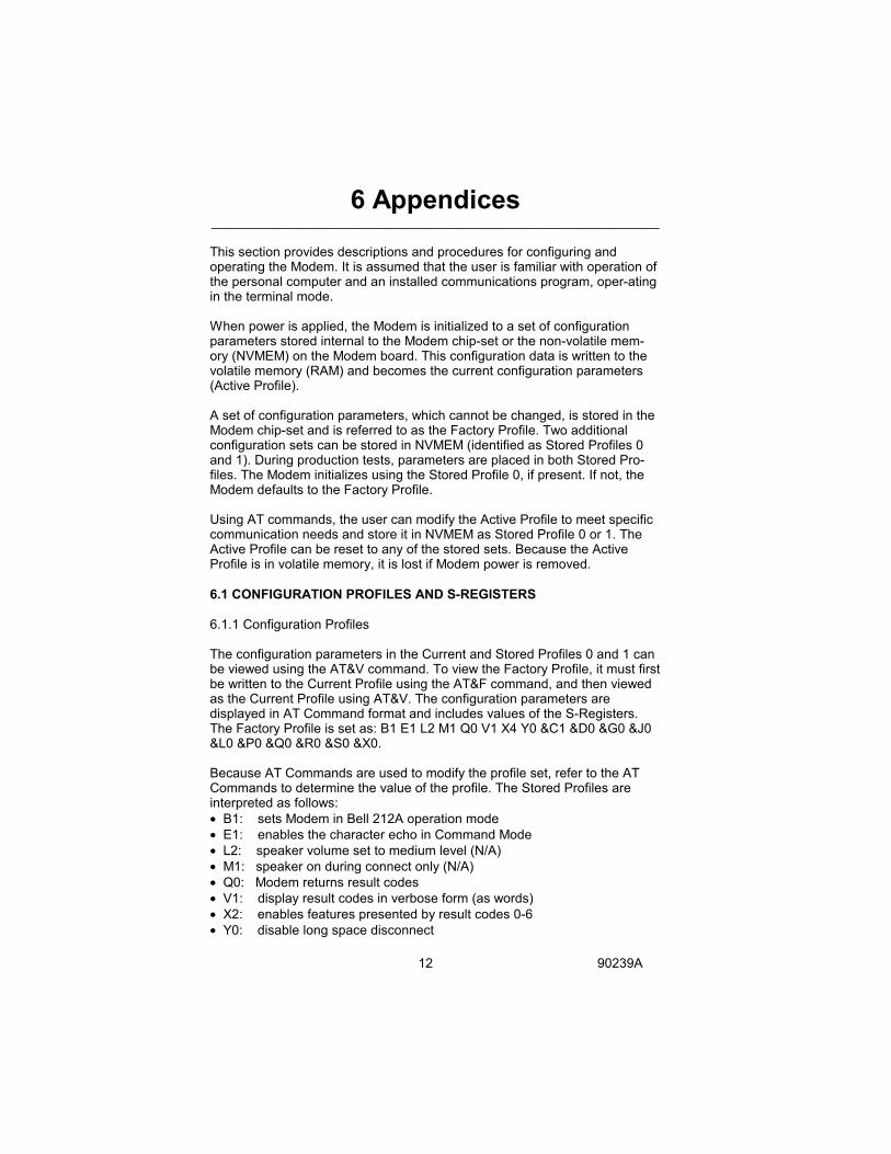
This section provides descriptions and procedures for configuring and operating the Modem. It is assumed that the user is familiar with operation of the personal computer and an installed communications program, oper-ating in the terminal mode. When power is applied, the Modem is initialized to a set of configuration parameters stored internal to the Modem chip-set or the non-volatile mem-ory (NVMEM) on the Modem board. This configuration data is written to the volatile memory (RAM) and becomes the current configuration parameters (Active Profile). A set of configuration parameters, which cannot be changed, is stored in the Modem chip-set and is referred to as the Factory Profile. Two additional configuration sets can be stored in NVMEM (identified as Stored Profiles 0 and 1). During production tests, parameters are placed in both Stored Pro-files. The Modem initializes using the Stored Profile 0, if present. If not, the Modem defaults to the Factory Profile. Using AT commands, the user can modify the Active Profile to meet specific communication needs and store it in NVMEM as Stored Profile 0 or 1. The Active Profile can be reset to any of the stored sets. Because the Active Profile is in volatile memory, it is lost if Modem power is removed. 6.1 CONFIGURATION PROFILES AND S-REGISTERS 6.1.1 Configuration Profiles The configuration parameters in the Current and Stored Profiles 0 and 1 can be viewed using the AT&V command. To view the Factory Profile, it must first be written to the Current Profile using the AT&F command, and then viewed as the Current Profile using AT&V. The configuration parameters are displayed in AT Command format and includes values of the S-Registers. The Factory Profile is set as: B1 E1 L2 M1 Q0 V1 X4 Y0 &C1 &D0 &G0 &J0 &L0 &P0 &Q0 &R0 &S0 &X0. Because AT Commands are used to modify the profile set, refer to the AT Commands to determine the value of the profile. The Stored Profiles are interpreted as follows: • B1: sets Modem in Bell 212A operation mode • E1: enables the character echo in Command Mode • L2: speaker volume set to medium level (N/A) • M1: speaker on during connect only (N/A) • Q0: Modem returns result codes • V1: display result codes in verbose form (as words) • X2: enables features presented by result codes 0-6 • Y0: disable long space disconnect

6 Appendices _____________________________________________________________
13 90239A
• &C1: DCD is on when carrier from remote Modem is detected • &D0: Modem ignores DTR signal • &G0: no guard tone • &J0: auxiliary telco leads disabled • &L0: Dial-Up Line (command not supported in Modem chip-set) • &P0: Pulse Dial Mode U.S. timing • &Q0: Asynchronous mode (same as &M0 command) • &R0: CTS tracks RTS • &S0: DSR always on • &X0: Modem generates internal transmit clock signal 6.1.2 S-Registers The S-Registers are memory locations that contain additional configuration data for Modem operation. Refer to Table 5 S-Registers, Page 23 for factory values stored in the S-Registers. Registers 13, 15, 19, 20 and 24 are used. The information in S-Registers 14, 21, 22, 23 and 27 is the bit-mapped data containing the accumulated information of all the other S-Registers, and is stored in the NVMEM. Any S-Register can be monitored using the AT command "ATSn?" ("Sn" represents the number of the registered to be viewed). For example, to view the value set in S-Register #1, enter the command "ATS1?". The value of a S-Register can be changed using the "ATSn=n" ("Sn" represents the number of the S-Register to change and "n" represents the new numeric value to be placed in the register). For example, to change the value of S-Register #1 to 3, enter the command as "ATS1=3". S-Register descriptions are as follows: S0 (Ring to Answer On): Sets the number of rings that the Modem is to automatically answer on. A value of 0 rings disables the automatic answer function of the Modem. The maximum ring setting is 255. S1 (Ring Count): The Modem uses this register to count the number of in-coming rings. If no rings occur for an eight second interval, the count is de-faulted to zero. S2 (Escape Sequence Character): This register contains the ASCII value of the escape sequence character (default value is the ASCII 43, the plus sign (+)). Values of 0-127 may be entered in this register. A value greater than 127 disables the escape sequence function, preventing the user from changing the Modem operation from the On-Line Mode to the Command Mode, while maintaining on-line connection with a remote system.
6 Appendices _____________________________________________________________
14 90239A
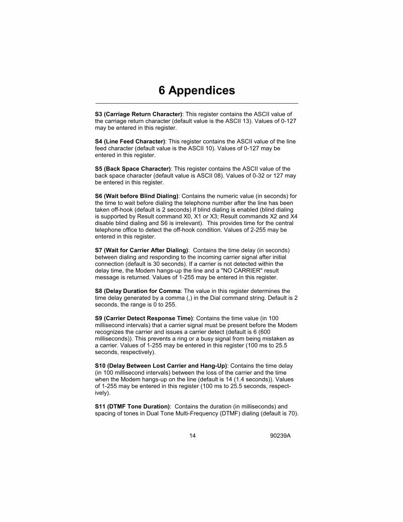
S3 (Carriage Return Character): This register contains the ASCII value of the carriage return character (default value is the ASCII 13). Values of 0-127 may be entered in this register. S4 (Line Feed Character): This register contains the ASCII value of the line feed character (default value is the ASCII 10). Values of 0-127 may be entered in this register. S5 (Back Space Character): This register contains the ASCII value of the back space character (default value is ASCII 08). Values of 0-32 or 127 may be entered in this register. S6 (Wait before Blind Dialing): Contains the numeric value (in seconds) for the time to wait before dialing the telephone number after the line has been taken off-hook (default is 2 seconds) if blind dialing is enabled (blind dialing is supported by Result command X0, X1 or X3; Result commands X2 and X4 disable blind dialing and S6 is irrelevant). This provides time for the central telephone office to detect the off-hook condition. Values of 2-255 may be entered in this register. S7 (Wait for Carrier After Dialing): Contains the time delay (in seconds) between dialing and responding to the incoming carrier signal after initial connection (default is 30 seconds). If a carrier is not detected within the delay time, the Modem hangs-up the line and a "NO CARRIER" result message is returned. Values of 1-255 may be entered in this register. S8 (Delay Duration for Comma: The value in this register determines the time delay generated by a comma (,) in the Dial command string. Default is 2 seconds, the range is 0 to 255. S9 (Carrier Detect Response Time): Contains the time value (in 100 millisecond intervals) that a carrier signal must be present before the Modem recognizes the carrier and issues a carrier detect (default is 6 (600 milliseconds)). This prevents a ring or a busy signal from being mistaken as a carrier. Values of 1-255 may be entered in this register (100 ms to 25.5 seconds, respectively). S10 (Delay Between Lost Carrier and Hang-Up): Contains the time delay (in 100 millisecond intervals) between the loss of the carrier and the time when the Modem hangs-up on the line (default is 14 (1.4 seconds)). Values of 1-255 may be entered in this register (100 ms to 25.5 seconds, respect-ively). S11 (DTMF Tone Duration): Contains the duration (in milliseconds) and spacing of tones in Dual Tone Multi-Frequency (DTMF) dialing (default is 70).

6 Appendices _____________________________________________________________
15 90239A
Values of 50-255 may be entered in this register. This value has no effect on the speed of pulse dialing (fixed at 10 pulses per second). S12 (Escape Sequence Guard Time): Contains the guard time (in 20 millisecond intervals) required prior to and following the escape sequence (default is 50 (one second)). It dictates the time that escape sequence (+++) must be entered. Values of 20-255 may be entered in this register. S25 (DTR Delay): Specifies the time (in 10 millisecond intervals) that a change in the DTR signal (on or off) must maintain before the Modem recognizes it (default is 5 (50 milliseconds)). Values of 0-255 may be entered in this register (0 to 2.55 seconds, respectively). S26 (CTS Delay): Specifies the time ( in 10 millisecond intervals) that the Modem waits after a transition of an incoming RTS signal before asserting the CTS signal (default is 1 (10 milliseconds)). Values of 0-255 may be entered in this register (0 to 2.55 seconds, respectively). 6.2 OPERATING MODES The Modem functions in one of two modes; Command Mode or On-Line Mode. Upon initialization (power-up), the Modem enters the Command Mode of operation. During the Command Mode the Modem operations are control-led by the AT commands. No data is being received or transmitted while in the Command Mode. The Modem goes to the On-Line Mode after making connection with a remote system and data is transmitted and received. During the On-Line Mode of operation the Modem can be temporarily inter-rupted to adjust operating parameters while maintaining connection with the remote system. An Escape Sequence of three pluses (+++) from the key-board or software interrupts the exchange of data, places the Modem in the Command Mode, and maintains on-line connection with the remote system. After parameters are changed using the AT commands of the Command Mode, the Modem returns to full on-line operations when the "ATO0" command is entered.

6 Appendices _____________________________________________________________
16 90239A
6.3 COMMAND MODE - AT COMMANDS The Command Mode uses AT commands to configure and operate the Modem. Each command requires the letters AT as a prefix. For example, to view the current value of S-Register #0 enter the command ATS0?". The only exception is the Repeat Command (A/). When "A/" is typed in, the Mo-dem repeats the last command line entered; the AT prefix and the <CR> or <ENTER> are not required. The command can be entered in all capitals (ATS0?) or all lower case letters (ats0?), but not mixed (Ats0?). The AT commands are executed when the Carriage Return Key (<CR>) or <ENTER> Key is pressed. Refer to Table 3 AT Commands, Page 17. Both alphabetical and numeric characters are used in the commands; the letter "oh" = "O" and the numeral "zero" = "0". Many of the AT commands require a specified parameter to be entered with the command. For example, the Echo Command requires the number 0 or 1 to be entered with the command to set the command to be off or on (ATE0 for echo off or ATE1 for echo on). If no parameter is included when the command is entered, the Modem uses a default parameter of 0. Some commands require a numeric value to be entered with the command, such as the command to set the Modem to answer on a specific number of rings. The S-Register #0 sets the count for the number of rings to answer on. To change the count of the S-Register #0 to three rings, enter the com-mand ATS0=3 (three being the specified numeric value). The command line can contain as many as 40 characters (spaces, the AT prefix, and the carriage return are not counted) and activate one or more AT commands. For example, a user wants to set the echo on and to configure the modem to answer on the third ring. The commands can be entered on two separate commands both requiring the AT prefix as follows: ATE1 ATS0=3 Or the commands can be entered on the same command, sharing the AT prefix as follows: ATE1 S0=3 ...or... ATE1S0=3 In the previous example, the first command line includes a space between the commands (ATE1 S0=3), the second command line does not (ATE1S0=3). The space between the E1 and S0=3 commands is not neces-sary, but makes it easier to evaluate the command line before activating it, especially for command lines including more than three commands (spaces are not counted as part of the 40 character maximum). The Modem command set consists of two types of commands: Immediate Commands and Set Commands. The Immediate Commands will always use
6 Appendices _____________________________________________________________
17 90239A
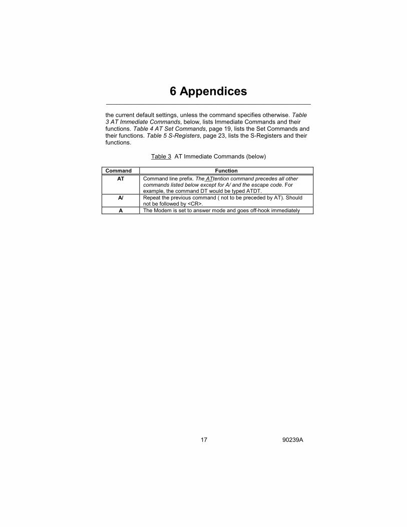
the current default settings, unless the command specifies otherwise. Table 3 AT Immediate Commands, below, lists Immediate Commands and their functions. Table 4 AT Set Commands, page 19, lists the Set Commands and their functions. Table 5 S-Registers, page 23, lists the S-Registers and their functions.
Table 3 AT Immediate Commands (below) Command Function
AT Command line prefix. The ATtention command precedes all other commands listed below except for A/ and the escape code. For example, the command DT would be typed ATDT.
A/ Repeat the previous command ( not to be preceded by AT). Should not be followed by <CR>.
A The Modem is set to answer mode and goes off-hook immediately

6 Appendices _____________________________________________________________
18 90239A
Command Function
Dn Dial the number immediately following this command where n is the number to be dialed, or that number combination with other dial modifiers shown below. Any combination of the dial modifiers listed below may be strung together to perform the desired dialing sequence. Modifier Function T Touch Tone dialing P Pulse dialing (default) R Reverse mode. Puts modem in answer mode immediately after dialing. W Wait for continuous tone before dialing the next number. Useful for dialing procedures requiring such a wait. The Modem waits for the number of seconds set by register S7 for the tone to occur. If tone is not heard, BUSY or NO DIALTONE is issued. @ Wait for a "quiet answer" - one or more rings followed by five se- conds of silence - for the length of time specified in register S7. , Pause the length of time specified by S8 (default = 2 sec.) Each comma equals the pause length specified. You may use as many commas as you like. ! Flash. This character can be used to go temporarily on-hook in order to get a new dialtone. (Note: some software uses ! as a carriage return. ; Remain in the command state after dialing. The semicolon can only be placed at the end of a dial command. S=n Dial stored number 0, 1, 2 or 3 that has been previously stored in non-volatile memory using the &Zn command. 0-9 # * ABCD characters that may be used in dialing; # * and ABCD are for tone dialing only Dial example 1: ATDT1234567 This example tells the Modem to tone dial the number 123-4567. Blank spaces within a command are ignored. Dial example 2: ATDP9W411,,,,, This example tells the Modem to pulse dial 9, wait for a second dialtone, tone dial the number 411, and pause 10 seconds. Further dial modifiers (but not commands!) could be added on the same line.
Command Function

6 Appendices _____________________________________________________________
19 90239A
Hn Controls the Modem on/off hook relay. n=0 on-hook (disconnected) n=1 off-hook
In Returns product ID/checksum n=0 returns product ID (249) n=1 returns ROM Checksum n=2 returns Checksum Test n=3 returns Product Revision n=4 returns Software Copyright
On Puts Modem in online data mode. n=0 online n=1 online with equalizer retrain sequence n=2 enable automatic retrain (default) n=3 disable automatic retrain
Zn Causes a software reset of Modem using the configuration profile stored in non-volatile memory. The value "n" repre-sents the configuration profile #0 or #1. If "n" is not desig- nated, profile #0 is defaulted.
Table 4 AT Set Commands (below)
Set commands are used to configure the Modem, allowing you to select operation speeds and standards, result code format and various other options. The default configurations are listed first. Command Function
Bn Selects V.22 or Bell 212A in the 1200 BPS mode. n=1 Bell 212A with 2225 Hz Answer Back Tone (default value) n=0 CCITT V.22 with 2100 Hz Answer Back Tone
En Determines whether the Modem echoes the data received in the command mode back to the local computer n=1 echo on (default) n=0 echo off
Ln Speaker volume (does not apply for this Modem) n=0 or 1 low n=2 medium n=3 high
Mn Speaker control (does not apply for this Modem) n=0 speaker off n=1 speaker on until carrier detected n=2 speaker always on n=3 speaker on after dialing until carrier detected
Command Function Qn Result codes on/off.
n=0 codes are sent n=1 codes are not sent
Sr? Reads the contents of status register r

6 Appendices _____________________________________________________________
20 90239A
Sr=n This command may be used to modify an S Register of the Modem. It assigns a value n to the status register r. Registers may be reset to the default values by issuing an '&F' or 'Z' command. See Table 5 S-Registers for a list of S Registers.
Vn See result code format. n=0 numeric n=1 words (plain English)
Xn Sets dialing mode result code format for dial command. The Vn command determines if the result code is sent as words or digits. n=0...Result codes enabled are OK/0, CONNECT/1, RING/2, NO CARRIER/3 and ERROR/4 n=1...Result codes enabled are OK, CONNECT, RING, NO CARRIER, ERROR and CONNECT (baud rate/1=300, 5=1200, 10=2400) n=2...Result codes enabled are OK, CONNECT, RING, NO CARRIER, CONNECT (baud rate) and NO DIAL TONE/6. n=3...Result codes enabled are OK, CONNECT, RING, NO CARRIER, ERROR, CONNECT (baud rate) and BUSY/7. n=4...Result codes enabled are OK, CONNECT, RING, NO CARRIER, ERROR, CONNECT (baud rate), BUSY and NO DIAL TONE/6.
Yn Long Space Disconnect Option. n=0 disabled n=1 enabled (disconnects if break greater than 1.6 seconds)
Zn Restore Configuration Profile in non-volatile RAM (NVMEM). n=0 Restore profile 0 (stored using &W0 command) n=1 Restore profile 1 (stored using &W1 command)
&Cn Data Carrier Detect Option. n=0 DCD always on n=1 DCD set by Modem when remote carrier detected
&Dn Data Terminal Ready Mode. DTR on/off time as specified by S25. n=0 Modem ignores DTR n=1 go to command mode if ON to OFF of DTR is detected n=2 same as n=1. Also disables auto answer n=3 initializes Modem from NVMEM when ON to OFF is detected
&F Sets values for S Registers and Commands to factory default. &Gn Guard Tone (used only in CCITT modes)
n=0 no guard tone (U.S. mode) n=1 1800 Hz n=2 550 Hz This command need never be used when communicating over U.S. phone lines. Outside the U.S., the Modem may need to generate an additional tone, along with its carrier, to disable echo suppressors in the central office. This tone varies by country.

6 Appendices _____________________________________________________________
21 90239A
Command Function
&Mn Communications Mode n=0 asynchronous n=1 synchronous during on-line operation; n=2 synchronous after OFF-to-ON of DTR and stored string is dialed n=3 synchronous when DTR is high
&Pn Pulse dial make/break ratio. n=0 USA and Canada mode n=1 UK mode
&Qn Same as &Mn &Rn CTS Control; if “0”, CTS tracks RTS; if “1”, CTS is always high (on) &Sn Data Set Ready option. DSR ON indicates that the Modem is
connected to a communication channel and is ready. n=0 DSR is always on (default) n=1 DSR turned on at start of handshaking, off in test mode, idle state or when carrier is lost
&Tn Controls Test Mode n=0 Ends current test and returns to command mode n=1 Initiates local analog loopback test n=3 Initiates local digital loopback test n=4 Pemits remote Modem digital loopback test n=5 Denys remote digital loopback test n=6 Initiates remote digital loopback test n=7 Initiates remote digital loopback test w/ self-test n=8 Initiates local analog loopback test w/ self-test
&V View Active and User Profiles; Displays active configuration profile and two user profiles stored in NVMEM.
&Wn Write Current Configuration Command. Stores configuration data in the active profile to one of the two user profiles in NVMEM. NOTE: Before the Write Current Configuration Command is issued, install configuration jumper J8 (Memory Write-Enable Jumper). WARNING: WHEN JUMPER J8 IS INSTALLED AND THE WRITE COMMAND IS ISSUED, THE EXISTING DATA STORED IN THE DESIGNATED USER PROFILE OF THE NVMEM IS DESTROYED! n=0 Store active profile in location 0 n=1 Store active profile in location 1
&Xn Asynchronous Data Transmission Clock Source n=0 Internal Clock n=1 External Clock (from computer) n=2 External Clock (from external modem)
&Yn Select Stored Profile on Power Up Option n=0 Select profile 0 on power up or hard reset n=1 Select profile 1 on power up or hard reset See the &Wn for particular command and S Registers stored
Command Function

6 Appendices _____________________________________________________________
22 90239A
&Zn=x Store Telephone Number. Stores up to four dialing strings in non-volatile memory for later recall using DS (dial stored number) command. Command format: &Z <up to 36 characters><CR> &Z= <up to 36 characters><CR> &Zn <up to 36 characters><CR> where n=0 to 3 If the delimiter (=) is not present, the characters following the &Z are treated as telephone numbers and/or modifiers and are stored in loca- tion 0. If the delimiter is present, the characters following it are stored in the location specified by the character preceding the delimiter (0 to 3). If not specified, 0 will be used. Allowable characters: 0 1 2 3 4 5 6 7 8 9 A B C D # * T P R W @ , ! ; NOTE: Before the Store Dialing Command is issued, install the configuration jumper J8 (Memory Write-Enable Jumper). WARNING: WHEN CONFIGURATION JUMPER J8 IS INSTALLED AND THE COMMAND IS ISSUED, THE EXISTING DATA STORED IN THE DESIGNATED MEMORY LOCATION OF NVMEM IS DESTROYED.
%Dn DTMF attenuation n=0 0 dB attenuation For n=1 to 7, attenuation = 2*n dB
%Ln Transmit attenuation n=0 0 dB attenuation For n=1 to 7, attenuation = 2*n dB
%J Secondary defaults. Resets all S register and command to the &F defaults with the following exceptions: S6 3 seconds; range 3-255 S11 95 ms; range: 60-255 %Ln 6 dB (%L3) %Dn 2 dB (%D1)
6 Appendices _____________________________________________________________
23 90239A
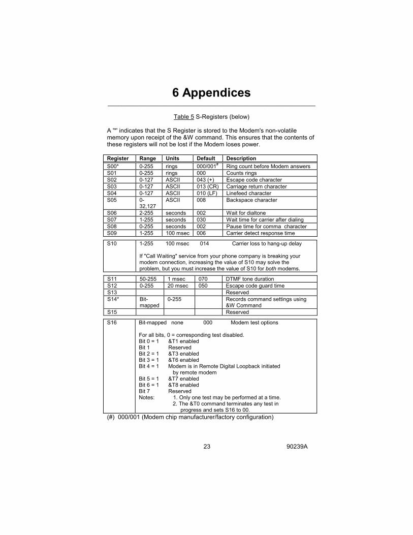
Table 5 S-Registers (below)
A '*' indicates that the S Register is stored to the Modem's non-volatile memory upon receipt of the &W command. This ensures that the contents of these registers will not be lost if the Modem loses power. Register Range Units Default Description S00* 0-255 rings 000/001# Ring count before Modem answers S01 0-255 rings 000 Counts rings S02 0-127 ASCII 043 (+) Escape code character S03 0-127 ASCII 013 (CR) Carriage return character S04 0-127 ASCII 010 (LF) Linefeed character S05 0-
32,127 ASCII 008 Backspace character
S06 2-255 seconds 002 Wait for dialtone S07 1-255 seconds 030 Wait time for carrier after dialing S08 0-255 seconds 002 Pause time for comma character S09 1-255 100 msec 006 Carrier detect response time
S10 1-255 100 msec 014 Carrier loss to hang-up delay If "Call Waiting" service from your phone company is breaking your modem connection, increasing the value of S10 may solve the problem, but you must increase the value of S10 for both modems.
S11 50-255 1 msec 070 DTMF tone duration S12 0-255 20 msec 050 Escape code guard time S13 Reserved S14* Bit-
mapped 0-255 Records command settings using
&W Command S15 Reserved
S16 Bit-mapped none 000 Modem test options For all bits, 0 = corresponding test disabled. Bit 0 = 1 &T1 enabled Bit 1 Reserved Bit 2 = 1 &T3 enabled Bit 3 = 1 &T6 enabled Bit 4 = 1 Modem is in Remote Digital Loopback initiated by remote modem Bit 5 = 1 &T7 enabled Bit 6 = 1 &T8 enabled Bit 7 Reserved Notes: 1. Only one test may be performed at a time. 2. The &T0 command terminates any test in progress and sets S16 to 00.
(#) 000/001 (Modem chip manufacturer/factory configuration)

6 Appendices _____________________________________________________________
24 90239A
Register Range Units Default Description S17 Reserved S18 0-255 seconds 000 Test duration timer.
Note: 0 = disable timer S19 Reserved S20 Reserved S21* Bit-
mapped
0-255 N/A Records command settings
S22* Bit-mapped
0-255 N/A Records command settings
S23* Bit-mapped
0-255 N/A Records command settings
S24 Reserved
S25* 0-255 10 msec 005 DTR delay. If &Q1 is selected, S25 is the delay in seconds after a connection has been made, but before the modem examines the DTR lead. If in the on-line or on-line command state, changes in DTR that last less than the time specified by S25, in 10 msec increments, are ignored by the Modem.
S26* 0-255 10 msec 001 RTS to CTS delay intervals. S27* Bit-
mapped
0-255 N/A Records command settings
S28* Bit-mapped
0-255 000 Records command settings
6 Appendices _____________________________________________________________
25 90239A
Modem Single-Input Logger DB-25S 15-Position I/O Connector TX 2 --------------------------- ------------- 12 Transmit (output) Red RX 3 ---------------------------- ------------- 10 Receive (input) Green SG 7 -------------------------------------------- 5 Common (ground) Black DCD 8 ----------------------------- ------------ 6 EDR (input) Blue DCD 8 ----------------------------- ------------ 9 CTS (input)** Yellow PTV 9 ---------------------------- ------------- 15 Power, +12 Vdc Orange **NOTE: No connection on GS-93 Logger Stevens Single-Input Loggers Modem MultiLogger DB-25S 9-Position Serial Connectors TX 2 ---------------------------- ------------- 2 Transmit (output) Red RX 3 ---------------------------- ------------- 3 Receive (input) Green SG 7 -------------------------------------------- 5 Common (ground) Black DCD 8 ---------------------------- ------------- 4 EDR (input) Blue PTV 9 --------------------------- -------------- 1 Power, +12 Vdc Orange Stevens MultiLogger NOTE: All wire colors refer to optional Stevens cables. All arrows refer to direction of signal or power flow.
Figure 4 Communications Cables, Stevens Loggers