research article proteus ii: design and evaluation of an ... · pdf filewe describe the design...
TRANSCRIPT
Research ArticleProteus II: Design and Evaluation of an IntegratedPower-Efficient Underwater Sensor Node
Wouter A. P. van Kleunen, Niels A. Moseley, Paul J. M. Havinga, and Nirvana Meratnia
University of Twente, 7500 AE Enschede, Netherlands
Correspondence should be addressed to Wouter A. P. van Kleunen; [email protected]
Received 5 June 2015; Revised 24 August 2015; Accepted 25 August 2015
Academic Editor: Wei Wang
Copyright © 2015 Wouter A. P. van Kleunen et al. This is an open access article distributed under the Creative CommonsAttribution License, which permits unrestricted use, distribution, and reproduction in any medium, provided the original work isproperly cited.
We describe the design and evaluation of an integrated low-cost underwater sensor node designed for reconfigurability, allowingcontinuous operation on a relatively small rechargeable battery for one month. The node uses a host CPU for the networkprotocols and processing sensor data and a separate CPU performs signal processing for the ultrasonic acoustic software-definedModulator/Demodulator (MODEM). A Frequency Shift Keying- (FSK-) based modulation scheme with configurable symbolrates, Hamming error correction, and Time-of-Arrival (ToA) estimation for underwater positioning is implemented. The onboardsensors, an accelerometer and a temperature sensor, can be used to measure basic environmental parameters; additional internaland external sensors are supported through industry-standard interfaces (I2C, SPI, and RS232) and an Analog to Digital Converter(ADC) for analog peripherals. A 433MHz radio can be used when the node is deployed at the surface. Tests were performedto validate the low-power operation. Moreover the acoustic communication range and performance and ToA capabilities wereevaluated. Results show that the node achieves the one-month lifetime, is able to perform communication in highly reflectiveenvironments, and performs ToA estimation with an accuracy of about 1-2 meters.
1. Introduction
Underwater Acoustic Sensor Networks (UASNs) can beused in many applications, such as monitoring underwaterpipelines, monitoring underwater drilling, and performingenvironmental monitoring [1]. Traditional approaches ofunderwatermeasuring involve deploying underwater sensorswith data logging capabilities and retrieving the sensorsafter recording several months of data. Such approach ofmonitoring provides no real-time monitoring, no reconfig-uration, and no failure detection capabilities. By providingcommunication capabilities to the sensors, it is possible toperform online monitoring and reconfiguration and realizeunderwater networks of nodes.
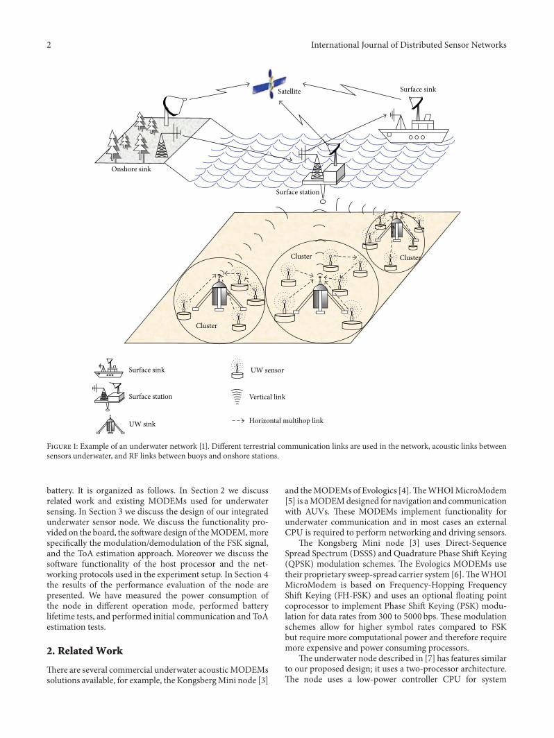
Figure 1 gives an example of how an underwater networkcan look like. Different communication links are used; forexample, in the underwater clusters, acoustic communicationcan be used to communicate data from different sensors to acluster-head.The cluster-headmay then use a long-range linkto forward the (possibly aggregated) data towards a surfacestation. A wireless RF link will forward the data to the shore,
or a satellite link may be used to communicate to the shore.Next to static sensors, Autonomous Underwater Vehicles(AUVs)may be used in the network to provide dynamic links.
One of the first realizations of UASNs is the Seawebprogram [2].This programhas performed several experimentdeployments with networks of underwater sensors and hasperformed experiments with modulation, communication,time synchronization, and positioning.
For our research purposes we require an underwatersensor node we can reconfigure to perform experimentswith physical, Medium Access Control (MAC), networking,and underwater monitoring applications. In addition, werequire the node to be flexible in terms of the internal andexternal sensors that can be connected. Tominimize networkmaintenance, maximizing battery lifetime is crucial. Our aimis to have a node lifetime of more than one month in lowtransmit duty cycle scenarios. Existing available commercialunderwater sensor nodes do not fit these requirements.
In this paper we describe our design of an underwateracoustic sensor node which combines sensing, processing,and communication powered by an integrated rechargeable
Hindawi Publishing CorporationInternational Journal of Distributed Sensor NetworksVolume 2015, Article ID 791046, 10 pageshttp://dx.doi.org/10.1155/2015/791046
2 International Journal of Distributed Sensor Networks
Satellite Surface sink
Surface sink
Onshore sink
Surface station
Surface station
Cluster
Cluster Cluster
Vertical link
Horizontal multihop linkUW sink
UW sensor
Figure 1: Example of an underwater network [1]. Different terrestrial communication links are used in the network, acoustic links betweensensors underwater, and RF links between buoys and onshore stations.
battery. It is organized as follows. In Section 2 we discussrelated work and existing MODEMs used for underwatersensing. In Section 3 we discuss the design of our integratedunderwater sensor node. We discuss the functionality pro-vided on the board, the software design of theMODEM,morespecifically the modulation/demodulation of the FSK signal,and the ToA estimation approach. Moreover we discuss thesoftware functionality of the host processor and the net-working protocols used in the experiment setup. In Section 4the results of the performance evaluation of the node arepresented. We have measured the power consumption ofthe node in different operation mode, performed batterylifetime tests, and performed initial communication and ToAestimation tests.
2. Related Work
There are several commercial underwater acousticMODEMssolutions available, for example, the KongsbergMini node [3]
and theMODEMsof Evologics [4].TheWHOIMicroModem[5] is aMODEMdesigned for navigation and communicationwith AUVs. These MODEMs implement functionality forunderwater communication and in most cases an externalCPU is required to perform networking and driving sensors.
The Kongsberg Mini node [3] uses Direct-SequenceSpread Spectrum (DSSS) and Quadrature Phase Shift Keying(QPSK) modulation schemes. The Evologics MODEMs usetheir proprietary sweep-spread carrier system [6].TheWHOIMicroModem is based on Frequency-Hopping FrequencyShift Keying (FH-FSK) and uses an optional floating pointcoprocessor to implement Phase Shift Keying (PSK) modu-lation for data rates from 300 to 5000 bps. These modulationschemes allow for higher symbol rates compared to FSKbut require more computational power and therefore requiremore expensive and power consuming processors.
The underwater node described in [7] has features similarto our proposed design; it uses a two-processor architecture.The node uses a low-power controller CPU for system

International Journal of Distributed Sensor Networks 3
management and a more powerful Digital Signal Processor(DSP) for the MODEM. The whole system can be placed ina low-power sleep mode when no acoustic communicationis performed. In receive mode, the node requires more than600mW to operate, which is too high for our purposes.
Many of the existing platformswere not designed for low-power operation. Moreover, commercial platforms are closeddesigns and the MODEMs software cannot be adapted toperform experiments.
TheMODEMsoutlined above donot provide the networklayer, the sensor integration, or the required data processingcapabilities to deploy completeUASNs. For the network layer,a networking library could be used.
An example of an external networking library whichcan drive various MODEMs using a separate CPU is theSunset framework [8].This framework allows using the samecode base for both simulation and deployment, easing thedevelopment of and the experimentation with the networklayer. This flexibility comes at a cost however; the frameworkrequires the Linux operating system, which runs on high-endpower consuming CPU. For example, their recommendedGumstix [9] platform draws between 0.5W and up to 1Weven when completely powered down. Simply running sucha system in standby mode for a month would require aminimumbattery capacity of 216Ah at 3.3 V,which is far frompractical.
Underwater sensor nodes that fit our (research) require-ments are simply not available. We therefore designed ourown low-power extensible nodes from the ground up.
In [10] we briefly described the design of our firstgeneration low-cost underwater node, the SeaSTAR node,based on a single ARM Cortex-M3 processor. The MODEMimplemented FSK modulation and ToA estimation. Thenode’s power consumption was still quite high because adevelopment board was used for the Cortex-M3. A 433MHzsurface radio interface was used for collecting measurementswhen the node was deployed at the surface.This proved to bevery useful for performing experiments and our new designalso incorporates a surface radio.
3. Design of the Underwater Sensor Node
The following section describes the hardware and softwaredesign of the Proteus II sensor node. First we will discuss thehardware components on the board and their functionality.The Proteus II sensor uses two processors, one for theMODEM functionality and one for theMAC and networkingprotocols. After discussing the hardware design, we discussthe software design of the HOST and theMODEMprocessor.We also discuss the physical modulation and packet formatof the acoustic communication and the ToA estimationapproach used for time synchronization and positioning.
The Proteus II sensor node (see Figure 2) is built aroundtwo low-cost low-power 32-bit ARM Cortex-M4 processors.The host CPU is responsible for the network protocolsand processing the data of onboard and optional exter-nal sensors. The second CPU is dedicated to the acousticMODEM functionality, which is implemented following
Figure 2: A picture of the Proteus board and enclosure. The boardand battery (not shown) are placed in the enclosure to make anintegrated underwater sensor node. Connectors on the lid of theenclosure allow external sensors to be connected.The lid is also fittedwith an RF connector for the 433MHz radio antenna.The node canbe completely submerged; however no 433MHz radio connectionwill be available when doing so. At the bottom end of the enclosure,the (black) acoustic transducer is visible and the transducer operatesin the frequency range of 20–40 kHz.
Host CPU Modem
Sensors radioSd card/memory
Externalsensor
interface
Data bus
433MHz
Figure 3: A block diagram showing the architecture of the Proteus IInode.The host CPU can transmit information to other nodes via theMODEM. Various subsystems, such as the sensors, SD card, and the433MHz radio, are interfaced to the host processor via the internaldata bus.
the software-defined radio paradigm [11]. The MODEMalso provides ToA estimation for time synchronization andpositioning.
TheMODEM needs to perform CPU-intensive decodingof the acoustic signal, requiring the processor to run inmaximum performance mode. The host CPU will mostly bedormant and run software timers to control the sensing andtransmission of data. This processor can therefore be run inthe very low-power run mode available on the CPU.
The onboard sensors, which consist of an accelerometerand a temperature sensor, can be used to measure basic envi-ronmental parameters such as surface wave characteristics,node orientation, and water temperature. The node supportsadditional internal or external sensors through its industry-standard digital serial interfaces (I2C, SPI, and RS232) andcan interface analog peripherals through a 16-bit ADC. A433MHz radio provides an additional way of communicationwhen the nodes are deployed on the water surface.
Figure 3 shows the architectural block diagram of theProteus II node.
3.1. Hardware Architecture. Figure 4 shows the componentsavailable on the Proteus II board. The board can be powered

4 International Journal of Distributed Sensor Networks
Modem CPUSD card Host CPU
Class Damplifier
Analog downmixerRS232 level-converterand external sensor interface
433
MH
z rad
io
5V regulator3.3V regulator
Figure 4: A photograph of the Proteus II PCB, showing the location of various subsystems, such as the CPUs, the receive downmixer, theamplifier, voltage regulators, SD card, and the 433MHz radio.
from a battery or an external power in the range of 12V–24V. The input voltage is converted to 3.3 V and 5V bytwo switching regulators. The regulators were selected forhigh energy efficiency even during the ultra low-power(sleep) operation. The 3.3 V regulator powers all the digitalcircuitry while the 5V regulator powers the analog part ofthe MODEM. When the MODEM is not operating, the 5Vregulator is turned off to save power. To further save power,the host processor is placed in low-power mode when thenode is sleeping.
In receivemode, the signal from the acoustic transducer isamplified, filtered, and downconverted to baseband, resultingin a quadrature signal. A 24-bit stereo sigma-delta is usedto convert the received signal into the digital domain whereit is further processed by the MODEM processor. The mainbenefit of using a sigma-delta converter is the much relaxedrequirements on the antialiasing filters. This reduces thedesign complexity and saves board space. Both the downcon-verter center frequency and the sample rate of the ADC areunder software control.
In transmitmode, an FSK signal is generated by toggling ageneral-purpose output pin through a timer on theMODEMprocessor. The output pin drives the class D amplifier andacoustic transducer. The timer, which is under softwarecontrol, directly determines the frequency of the FSK signal.
The Proteus II node has several sensors and sensor inter-faces on board. The onboard sensors are an accelerometer(ADXL362) and a temperature sensor. Additional analog anddigital sensors are supported through the onboard 16-bitADC and the serial interfaces (I2C, SPI, and RS232-levelUART), respectively. For data logging, the node can be fittedwith an SD card. Finally, the node features a 433MHz radiofor RF communication. This, however, only works when thenode is deployed at the surface.
Figure 2 illustrates the Proteus II board and the designedenclosure. Rechargeable Lithium-Polymer (LiPo) batterypacks of up to 5000mAh@12V fit into the enclosure to powerthe board.
With the integrated sensors, data processing, and com-munication capabilities the node is an integrated flexiblesensor platform.
3.2. Software Architecture: Host Processor. The host processorhas many duties. It processes the data from the sensors,runs the network and routing layer software, drives theMODEM, and controls the 433MHz radio. The 433MHzradio is used for network debugging, configuring the sensors,and performing time synchronization when the sensor hasbeen deployed at the water surface. In addition, the hostprocessor is responsible for the power management of thenode.
Because the host processor is an embedded processor,with limited memory (64 kb) available and no MemoryProtection Unit (MPU), an operating system such as Linuxwill not run on this processor. It is our believe that small,energy optimized operating systems such as FreeRTOS [12]or TinyOS [13] are more suited for energy-efficient sensors.
Inspired by these small (real-time) operating systems, wehave implemented the Proteus II operating system.This runson both the host and the MODEM processor. The operatingsystems consist of a low-power time scheduling framework.Different periodic tasks can be scheduled and the operatingsystems control that when idling, the host processor goesinto a low-power sleeping state with wakeup timers running.Moreover the operating system is able to handle events, suchas incoming SPI or UART communication or a radio packetarriving from the 433MHz radio, waking up the processorfrom low-power mode when such event occurs.
Using this operating system, the different processorscan be placed in sleep mode. The MODEM processor andassociatedMODEMelectronics are put into sleepmodewhenno communication is required. This is controlled by the hostprocessor through the SPI interface.Thehost processor is ableto run on awakeup timer and shut down theMODEM. In thismode, the overall power consumption of the node is reducedto less than 8mW.
In our test network we have implemented a time-divisionmultiple access (TDMA) network protocol designed forperforming experiments. Because we wanted to evaluate thePacket Delivery Rate (PDR) achievable by the node withinour test environment, we used TDMA protocol to avoidcollisions. The networking protocol uses both the RF radioand the underwater MODEM to perform communication.

International Journal of Distributed Sensor Networks 5
Markdetector
Spacedetector
ADC
Timingrecovery
MLSEdetector Bits outAcoustic
transducer
Downconverter
Class Damp.
ToAcorrelator ToA out
Modulator Bits in
SoftwareHardware
−+
Figure 5: A block diagram of the hardware and software partitioning of the MODEM physical layer. In the receive path, the acoustictransducer signal is sampled and downconverted to baseband. Two tone detectors detect the energy at theMark (1) and Space (0) frequencies.A maximum-likelihood sequence estimator (MSLE) performs the symbol detection and timing-recovery and then it outputs the receivedbits. In the transmit path, a modulator converts the incoming bits into symbols. The symbols are amplified and transmitted by the acoustictransducer.
Time is divided in 4-second timeslots and nodes in thenetwork are assigned a static timeslot before deploying thenetwork. The gateway uses the RF radio to poll the differentsensors in their assigned timeslots. In the poll message to thesensor the following data is included.
(i) Command. It indicates what type of message should betransmitted by the sensor: a Time-of-Flight (ToF) beacon, asensor measurement or nothing should be transmitted at all.During our tests we transmit 3 ToF measurements and everyfourth packet is a measurement packet which includes mea-surements from the accelerometer and temperature sensor.
(ii) Baud Rate. It indicates what baud rate should be used forthe acoustic transmission when sending the acoustic packet.
(iii) Timestamp. It indicates the current time of the gateway. AToF beaconmessage includes this timestamp, such that whenthe packet arrives at the gateway, the round-trip time can becalculate.
The poll message indicates what type of packet should betransmitted by the sensor and what settings should be used.Upon a poll message, the sensor will reply with a statisticsmessage using the RF radio.
(iv) Battery Power. It indicates the battery power voltagereading.
This setup allows us to configure the behaviour of thesensors and provides debugging information. It allows usto centrally control the network, experiment with baudrates, and perform ToF and PDR measurements. In futurework we would like to extend this with configuration ofthe packet type (BCH or Reed-Solomon with configurederror correction overhead) and with routing information(indicating which sensors should send to which sensor).
The described networking protocol is geared towards a testnetwork, for experimenting with physical, MAC networking,routing, and positioning algorithms, and the intended usageof the network.
Because we use a TDMA approach, the sensor is ableto sleep between the polling cycles, thereby reducing thepower consumption of the sensor. In other projects thehost processor can be reconfigured for supporting differentsensors, performing networking algorithms, and positioningor implementing network security using data encryption andvalidation.
3.3. Software Architecture: MODEM Processor. Followingthe software-radio paradigm, the majority of the acoustictransmit and receive functions are implemented in softwareand run on the MODEM processor. Figure 5 shows thehardware/software partitioning of the physical layer.
The Proteus II uses FSK modulation with fixed frequen-cies around 21 kHz. FSK is chosen for its low computa-tional complexity, its relatively good multipath resilience,and its constant envelope property, which greatly simplifiesthe power amplifier design. Communication speed of theMODEM is slow (10 to 200 baud), but the speed can beimproved in the future by using multitone FSK.
In the receivemode, the quadrature baseband signal fromthe ADC is processed by two tone detectors, which operateat 8 ksps sampling rate. Their outputs are resampled at 16times the baud rate to reduce the computational complexityof the following processing blocks. A maximum-likelihoodsequence estimator is used to determine the most likely 4-symbol sequence of themost recently received data.Then bitsare extracted and if necessary, the symbol timing is adjusted.The resulting bit-stream is fed into the packet decoder. SeeFigure 5 for an overview of the physical layer processing.

6 International Journal of Distributed Sensor Networks
Sync Preamble Len Payload CRC
Figure 6: Proteus II packet format: the packet consists of syncbits for time synchronization, a preamble with low autocorrelationproperties to allow for ToA estimation, and packet start detection.The payload of the packet is modulated using the Hamming errorcorrecting approach. The CRC is used for validation of the packetdata upon reception.
The packet format used by the Proteus II node is definedas follows. The packet consists of several sync bits (10101010),which allows the bit synchronization to be performed beforethe actual data of the packet data is received; see Figure 6. It isfollowed by a Barker sequence preamble [14].TheBarker codehas low autocorrelation properties allowing accurate packetarrival detection and ToA estimation. Bit synchronizationand ToA estimation are further improved by using data-whitening on the packet payload. Error protection is providedthrough a low-complexity Hamming code based ForwardError Correction (FEC) scheme and a Cyclic RedundancyCheck (CRC).
After the sync bits and Barker code preamble, the lengthof the payload (including its CRC) is transmitted. The 16-bitCRC is added at the end of the packet to validate the packetupon reception. A CRC polynomial was selected which hasgood bit-error detecting properties [15]. Every 32-bit block ofthe payload and CRC is extended with a 6-bit parity blockfor storing the parity bits produced by the Hamming errorcorrection code. This is shown in Figure 7.
Data-whitening is applied to the len + payload + CRCbits of the packet. This is done to reduce the autocorrelationproperties of the packet payload, thereby improving the ToAestimation performance, and to increase the number of Markto Space transitions required by the demodulator to performbit synchronization.
3.4. ToA Estimation. The MODEM performs ToA for sup-porting ToF or Time-Difference-of-Arrival (TDoA) localiza-tion. The ToA can be determined by cross-correlating thetransmitted signal and the received signal which is bufferedby theMODEM.The sampling rate of the signal is dependenton the configured symbol rate of the MODEM. The energy-detector of the MODEM samples the signal at 16x thesymbol rate.Therefore when the symbol rate of the MODEMis increased, the sampling rate is increased and the ToAestimation is expected to be more accurate.
Once a packet is correctly received, this can be deter-mined by verifying the CRC, the fixed preamble, and a part ofthe decoded packet is used to perform the cross-correlation.The Barker sequence in the header and the whitened data ofthe packet improve the cross-correlation capabilities of thepacket.
After cross-correlation is performed, the correlationshows the signal response of the acoustic channel. Thisresponse may contain several multipath arrivals of the signal.The strongest arrival may not necessarily be the first or line-of-sight arrival. Therefore the cross-correlation needs to besearched to estimate the first path arrival. In [16] several
Len Payload CRC
ECC ECC ECC ECC6-bits 6-bits 6-bits 6-bits32-bits
32-bits 32-bits
32-bits
32-bits 32-bits
32-bits 32-bits
Figure 7: Hamming based error correction is performed onsubblocks of the payload + CRC. The number of error correctionbits for the Hamming code is fixed and error correcting capabilitiesfor the Hamming code cannot be configured.
techniques for estimating ToA of ultrawideband (UWB)signals have been proposed. These algorithms can also beused for estimating the arrival of an acoustic signal. We usethe “search and subtract” algorithm [16], which works asfollows:
(1) Find the strongest arrival in the cross-correlation.(2) Set the first arrival threshold to 1/4 of the peak of the
strongest arrival.(3) Subtract the strongest arrival from the cross-cor-
relation result.(4) Search again for the next strongest arrival that is
received before all other strongest arrivals and isstronger than 1/4 of the strongest arrival.
(5) Subtract this arrival and go back to step (4).
The process of finding an earlier arrival in the cross-correlation and attempting to determine the first arrival ofthe signal rather than the strongest arrival is repeated upto 4 times or is halted earlier if no strong arrival peak canbe found. Repeating the algorithm (4 times) represents themaximum number of earlier multipath arrivals we expect tobe able to detect.
4. Performance Evaluation
The following section describes the performance evaluationwe have performed on the Proteus II node.We have evaluatedthe power consumption of the node in different state and wemake an estimation whether one-month lifetime is achiev-able. We have performed a lifetime test with a high duty cycleand a low duty cycle; in the low duty cycle test we achieve alifetime of one month. Next to the lifetime tests, we evaluatethe PDR and ToA estimation of the node. Moreover we haveevaluated the maximum communication range of the node.
4.1. Power Consumption. We have measured the power con-sumption of the node during acoustic transmission, acousticreception, and idle and with the 433MHz radio enabled.Results are shown in Table 1. Transmission means that anacoustic packet is being transmitted; reception indicates thatthe MODEM is listening for the reception of an acousticpacket. In the idle state the acoustic MODEM is turned offand the host processor is running a sleep timer to wake up thehost periodically and radio that indicates the 433MHz radiois turned on. As can be seen the acoustic MODEM transmitsat about 8W; during reception the MODEM uses 300mW.

International Journal of Distributed Sensor Networks 7
Table 1: Power consumption of the node in different states.
State Power (W) DescriptionTransmission 8W Active acoustic transmissionReception 300mW Active packet receptionIdle 60mW Node sleeping on wakeup timer
Idle (fix) 8mWNode sleeping on wakeup timerafter disabling the RS232level-converter
Radio 200mW 433MHz radio active
Table 2: Estimation of the battery capacity required for a batterylifetime of one month.
State Duty cycle Power (mW) Total (mWh)Idle 1 8 5952Transmission 12/3600 8000 19840
Battery capacity required (mWh) 25792Battery capacity 5000mAh at 12V (mWh) 60000
Initially with the MODEM turned completely off and thehost running on a wakeup timer and being in sleep modethe complete node consumed 60mW. This was higher thanwhat should have been achievable with the design. Later, wediscovered that the RS232 level-converter was still in standbymode and after disabling the RS232 level-converter, the idlepower consumption of the node dropped to 8mW. Using thisidle power consumption, one month of monitoring can beeasily achieved using different communication patterns.
Table 2 gives an indication of the battery capacityrequired to run the node for onemonth (31×24 = 744 hours).The idle power consumption of the node is always present(duty cycle is 1). For the transmission we assume a duty cycleof 12 seconds for every hour (3600 seconds).The total batterycapacity required is about 25792mWh, which indicates thata battery of 5000mAh@12V (60000Wh) is more thansufficient, and leaves plenty of room for self-discharge of thebattery. The calculation indicates that a battery of 5000mAhis more than sufficient to run the node for one month. Sucha battery fits in the enclosure; therefore we can say thatwe can achieve the required one-month operation; otherconfigurations are also possible. In Section 4.3 we performlifetime test with different transmission duty cycles.
4.2. Packet Delivery Rate. Figure 8 shows our Packet DeliveryRate (PDR) setup. Four nodes and one gatewaywere deployedin an artificial lake at the University of Twente campus.The acoustic communication is performed underwater whilea radio connection to the gateway is used to collect themeasurement data. Acoustic communication was performedin the 20–22 kHz band; the same frequencies were used forthe different baud rates.The deployment of the node with theacoustic transducer underwater and the radio antenna abovethe water surface is shown in Figure 9. The test environmentis shown in Figure 10; a lot of concrete is present in the formof walls, pillars, and the lake floor. The communication istherefore highly influenced by many multipaths.
Gateway
Position 1Position 2
Position 3
Position 4
Figure 8: Illustration of the PDR setup deployment. The nodeswere placed at different distances from the gateway and the watercontinues under the shown building.
Figure 9: A Proteus II node deployed in the water at the test setup.The acoustic part of the node is underwater and the radio antenna isabove thewater surface to allow a radio connectionwith the gateway.
All the nodes have a single-hop connecting to the gateway.Packets were transmitted for a period of 22 hours at differentsymbol rates (50, 100, and 150 baud). The PDR rate wascalculated for this setup. Results shown in Figure 11 indicatethat about 30–40% PDR is achieved in this environment.When the symbol rate is increased to 150 bps, the deliveryrate of two nodes decreases to only a couple of percent. Inthis case, the multipath causes these nodes to be unable tocommunicate.
Figure 12 gives an indication of the pattern of packetloss. Shown in the graph are the received packet numbers ofthe gateway, with their respective receive time. The packetnumbers cycle from 0 to 64 before wrapping back to 0 andideally all should be received.What can be seen is that certainperiods of time experience little packet loss, while otherperiods of time experience a significant packet loss. Whatcauses this effect is still unclear to us; possibly this is the resultof the node slightly moving in the water and experiencingdifferent multipath effects for an extensive period.
4.3. Lifetime. In the same setup we have performed two life-time tests. With a transmission interval of every minute, per-forming a transmission of 1 second every minute, the nodeswere able to communicate for 5 days using a 2200mAh@12V

8 International Journal of Distributed Sensor Networks
Figure 10: Picture of the deployment in the artificial lake at theUniversity of Twente campus. The environment is a small lakebetween office buildings and consists of concrete walls and floor.The gateway node was placed near an office to allow a networkconnection to be made to campus network, allowing access tothe testbed through internet. The nodes are kept floating with theradio antenna above the water surface, to allow a radio connectionto the gateway for collecting measurement data, and are fixedwith a sandbag on the floor. The acoustic transducer is deployedunderwater and acoustic communication is performed through thewater.
50 baud 100 baud 150 baudPosition 1 36.72% 26.55% 3.61%Position 2 36.72% 51.98% 33.81%Position 3 31.41% 19.44% 1.03%Position 4 46.33% 49.04% 27.42%Avg. 37.80% 36.75% 16.47%
0.00
10.00
20.00
30.00
40.00
50.00
60.00
Pack
et d
eliv
ery
rate
(%)
Figure 11: Results of the PDR test shown are the percentage ofpackets that were correctly delivered to the gateway over a periodof 22 hours for different symbol rates.
rechargeable battery. In Table 3 we show the calculation ofthe required energy for these 5 days. For the transmissionthe duty cycle was 60 seconds for every hour (3600 seconds).The energy required was 23200mWh; this is in line withthe capacity of the battery we used (2200mAh@12V =26400mWh).The calculated consumed energy is in line withthe battery capacity that we calculate.
In another test we have equipped the node with a5000mAh@12V battery. With a low duty cycle, a transmis-sion of 2 seconds every 10 minutes, we have achieved a one-month lifetime of the underwater node. This shows that ourset goal, a lifetime of one month using a low duty cycle, isachievable.
Table 3: Estimation of the battery capacity required for the lifetimetest over a duration of 5 days.
State Duty cycle Power (mW) Total (mWh)Idle 1 60 7200Transmission 60/3600 8000 16000
Battery capacity required (mWh) 23200Battery capacity 2200mAh at 12V (mWh) 26400
010203040506070
14:24 15:36 16:48 18:00 19:12 20:24 21:36 22:48 0:00
Pack
et n
umbe
r
Arrival time
Node 1Periods of extensivepacket loss
Figure 12: Arrival of packets at the gateway over the period of 10hours.The received packet numbers at the time they are received areshown; packet numbers cycle from 0 to 64. What can be seen is thatcertain periods of time show little packet loss, while other periodsof time experience significant packet loss.
4.4. Time of Arrival. In a different setup, ToA estimation wasevaluated. Using two nodes we estimate the range betweentwo nodes by using the radio and an acoustic transmission.Themaster node transmits a radio packet to the slave node tostart a transmission. The slave node replies with an acousticpacket and the master node determines the round-trip timeof the radio and acoustic transmission.
The distance between the two nodes was changed fromthe two nodes deployed completely next to each other (0-meter distance) to 10, 20, and 30 meters (setup shown inFigure 13). The distance of 0 meters is used to determine theprocessing delay of the measurement.The results can be seenin Figure 14.
Our results show that ToA of the MODEM is able to esti-mate the distance between the nodes in the experiment. Asexpected, when the symbol rate is increased the accuracy ofToA measurement and consequently distance measurementsalso increases. At the distance of 30 meters, the MODEMappears to lock on to a multipath arrival rather than thedirect line-of-sight. A relative distance of about 40 meters ismeasured, rather than the expected 30 meters. This result isthe same for all symbol rates.
ToA estimation based on modulated signals remains dif-ficult and is affected by multipath. Even with the “search andsubstract” algorithm described in Section 3.4, the MODEMstill locks on the multipath arrivals in some cases. ToAestimation based on wideband chirps is definitely moreaccurate. Experiments with a chirp signal in highly reflectiveenvironments were performed in [10, 17]. The performanceof the ToA estimation can be increased using multitone FSKand therefore using a wider band for the signal.

International Journal of Distributed Sensor Networks 9
Position 3
Position 4
Position 2
Position 1
0
20
m30.04
m
Figure 13: Illustration of the ToF setup deployment. The ToF wasmeasured at four different positions ranging in distance from 0m to30m. How well the distance between the different positions can beestimated using the ToA measurement was evaluated.
50 baud 100 baud 150 baud12.11 12.37 11.9522.73 20.87 20.7942.03 39.95 39.62
0.005.00
10.0015.0020.0025.0030.0035.0040.0045.00
Mea
sure
d di
stan
ce (m
)
10m20m30m
Figure 14: Measured distance between Proteus II nodes at differentsymbol rates and at different distances.
In the same environment as the ToA setup, maximumcommunication range tests indicate that the node is able tocommunicate over a distance of 140m. Because the matchingof the transducer is very much frequency dependent, webelieve the range can be improved by tuning the frequencyof the communication. For our current setup the FSK werefixed in the band of 20–22 kHz.
5. Conclusion
For our future research we require an underwater sensornode which can be reconfigured at all networks layers, thephysical layer up to the transport layer. Moreover, we requirea node which can be extended with different sensors. Theunderwater node should be able to run on a rechargeable
battery for one month and, ideally, the node should also beof low cost.
Because existing commercial nodes do not allow recon-figuration of the physical layer protocols in theMODEM andexisting research platforms were not available to us or did notmeet our energy efficiency criteria, we have designed our ownunderwater sensor node called Proteus II.
This node has an energy-efficient power circuit and isdesigned for low-power operation; a lithium battery insidethe enclosure powers the sensor node. The node has inte-grated sensors such as an accelerometer and temperaturesensor and ADC allows connecting analog sensors. Externalsensors can be connected through connectors available on theenclosure.
A 433MHz radio is available on the node to allow aradio connection for debugging and collecting measurementdata when the node is deployed at the water surface. In ourtest a TDMA MAC protocol was implemented to preventcollisions. Sensors are polled by the gateway using the RFradio; this allows us to control, configure, and diagnose thenetwork centrally.
The node consists of a low-powerMODEMand host con-troller both based on a Cortex-M4 processor. The MODEMis designed as a software-defined MODEM and uses FSKmodulationwithHamming error correction andToA estima-tion for positioning and time synchronization. Bit decodingand bit synchronization are performed using maximum-likelihood decoding and ToA estimation is performed usingcross-correlation with “search and substract” algorithm forestimation of first arrival and multipath arrivals. The hostprocessor is used for performing networking, reading theonboard sensors, and controlling the 433MHz radio.
Tests were performed tomeasure the power consumptionand performance of the node. In low-power mode, the nodedraws about 8mW. In a lifetime test we have achieved thedesired one-month lifetime, using a 5000mAh@12V batteryand a duty cycle of transmitting 2 seconds every 10 minutes.
Initial communication tests in our test environment showthat the Proteus II is able to achieve a PDR of 30–40% inan environment which has concrete walls and floors andis therefore highly reflective. Moreover, communication wasperformed over the distance of 140m.
ToA estimation was also evaluated and the fact thatthe MODEM is able to perform ToA estimation with anaccuracy of about 1 to 2 meters was shown. The ToA basedon the modulated FSK signal is still affected by multipathinterference.
In the future, multitone FSK and perhaps PSK will beresearched to see if an improvement can be made in com-munication speed and ToA by using a wider band signal.Multitone FSK likely has a positive effect on the deliveryrate, because many multipaths are present within the envi-ronment. We would also like to evaluate the performanceof our nodes in less reflective environments. The maximumcommunication range of 140m can also be improved inthe future by tuning the frequency to the matching ofthe transducer. In our experiments the used frequencieswere fixed; by allowing configurable frequencies, the use ofdifferent frequencies can be evaluated.

10 International Journal of Distributed Sensor Networks
Conflict of Interests
The authors declare that there is no conflict of interestsregarding the publication of this paper.
Acknowledgment
This work was funded through the European FP7 projectSUNRISE, under Grant no. 611449.
References
[1] I. F. Akyildiz, D. Pompili, and T.Melodia, “Underwater acousticsensor networks: research challenges,” Ad Hoc Networks, vol. 3,no. 3, pp. 257–279, 2005.
[2] J. Rice, B. Creber, C. Fletcher et al., “Evolution of seaweb under-water acoustic networking,” in Proceedings of the MTS/IEEEConference and Exhibition (OCEANS ’00), vol. 3, pp. 2007–2017,IEEE, Providence, RI, USA, September 2000.
[3] T. S. Husøy, F. R. Knudsen, B. Gjelstad, and A. Furdal, “Productdevelopment at kongsberg maritime related to underwatersensor networks,” in Proceedings of the 7th ACM InternationalConference on Underwater Networks and Systems (WUWNet’12), pp. 16:1–16:5, ACM, New York, NY, USA, November 2012.
[4] Evologics, http://www.evologics.de/.[5] L. Freitag, M. Grund, S. Singh, J. Partan, P. Koski, and K. Ball,
“The WHOI micro-modem: an acoustic communications andnavigation system for multiple platforms,” in Proceedings of theMTS/IEEE OCEANS Conference, vol. 2, pp. 1086–1092, IEEE,Washington, DC , USA, September 2005.
[6] R. Bannasch and K. Kebkal, “Method and devices for transmit-ting and receiving information,” US Patent 6,985,749, 2006.
[7] Y. Yang, Z. Xiaomin, P. Bo, and F. Yujing, “Design of sensornodes in underwater sensor networks,” in Proceedings of the4th IEEE Conference on Industrial Electronics and Applications(ICIEA ’09), pp. 3978–3982, May 2009.
[8] C. Petrioli, R. Petroccia, and D. Spaccini, “SUNSET version2.0: enhanced framework for simulation, emulation and real-life testing of underwater wireless sensor networks,” in Proceed-ings of the 8th ACM International Conference on UnderwaterNetworks and Systems (WUWNet ’13), pp. 43:1–43:8, ACM,Kaohsiung, Taiwan, November 2013.
[9] Gumstix, http://www.gumstix.com/.[10] W. A. P. van Kleunen, N. A. Moseley, N. Meratnia, and P. J. M.
Havinga, “Experiments with aLS-Coop-Loc cooperative com-bined localization and time-synchronization,” in Proceedings ofthe 12th International Symposium onModeling andOptimizationinMobile, AdHoc andWireless Networks (WiOpt ’14), pp. 86–91,IEEE Computer Society, Hammamet, Tunisia, May 2014.
[11] J. Mitola, “The software radio architecture,” IEEE Communica-tions Magazine, vol. 33, no. 5, pp. 26–38, 1995.
[12] FreeRTOS, A free open source rtos for small embedded realtime systems, http://www.freertos.org/.
[13] P. Levis, S. Madden, J. Polastre et al., “Tinyos: an operatingsystem for sensor networks,” in Ambient Intelligence, pp. 115–148, Springer, Berlin, Germany, 2005.
[14] S. W. Golomb and R. A. Scholtz, “Generalized barker sequen-ces,” IEEE Transactions on InformationTheory, vol. 11, no. 4, pp.533–537, 1965.
[15] P. Koopman and T. Chakravarty, “Cyclic redundancy code(CRC) polynomial selection for embedded networks,” in Pro-ceedings of the International Conference on Dependable Systemsand Networks, pp. 145–154, IEEE, June-July 2004.
[16] C. Falsi, D. Dardari, L. Mucchi, and M. Z. Win, “Time ofarrival estimation for UWB localizers in realistic environ-ments,” Eurasip Journal on Applied Signal Processing, vol. 1,Article ID 032082, 2006.
[17] B. S. Borowski, Application of channel estimation to underwater,acoustic communication [Ph.D. thesis], Stevens Institute ofTechnology, Hoboken, NJ, USA, 2011, AAI3467242.

International Journal of
AerospaceEngineeringHindawi Publishing Corporationhttp://www.hindawi.com Volume 2014
RoboticsJournal of
Hindawi Publishing Corporationhttp://www.hindawi.com Volume 2014
Hindawi Publishing Corporationhttp://www.hindawi.com Volume 2014
Active and Passive Electronic Components
Control Scienceand Engineering
Journal of
Hindawi Publishing Corporationhttp://www.hindawi.com Volume 2014
International Journal of
RotatingMachinery
Hindawi Publishing Corporationhttp://www.hindawi.com Volume 2014
Hindawi Publishing Corporation http://www.hindawi.com
Journal ofEngineeringVolume 2014
Submit your manuscripts athttp://www.hindawi.com
VLSI Design
Hindawi Publishing Corporationhttp://www.hindawi.com Volume 2014
Hindawi Publishing Corporationhttp://www.hindawi.com Volume 2014
Shock and Vibration
Hindawi Publishing Corporationhttp://www.hindawi.com Volume 2014
Civil EngineeringAdvances in
Acoustics and VibrationAdvances in
Hindawi Publishing Corporationhttp://www.hindawi.com Volume 2014
Hindawi Publishing Corporationhttp://www.hindawi.com Volume 2014
Electrical and Computer Engineering
Journal of
Advances inOptoElectronics
Hindawi Publishing Corporation http://www.hindawi.com
Volume 2014
The Scientific World JournalHindawi Publishing Corporation http://www.hindawi.com Volume 2014
SensorsJournal of
Hindawi Publishing Corporationhttp://www.hindawi.com Volume 2014
Modelling & Simulation in EngineeringHindawi Publishing Corporation http://www.hindawi.com Volume 2014
Hindawi Publishing Corporationhttp://www.hindawi.com Volume 2014
Chemical EngineeringInternational Journal of Antennas and
Propagation
International Journal of
Hindawi Publishing Corporationhttp://www.hindawi.com Volume 2014
Hindawi Publishing Corporationhttp://www.hindawi.com Volume 2014
Navigation and Observation
International Journal of
Hindawi Publishing Corporationhttp://www.hindawi.com Volume 2014
DistributedSensor Networks
International Journal of