models: 10/15/20reod/reozd - pm technologies ... 10/15/20reod/reozd controller: adc 2100 advanced...
TRANSCRIPT
Industrial Generator Sets
Models:
10/15/20REOD/REOZD
Controller:ADC 2100 Advanced Digital Control
TP-6392 8/05
Operation

TP-6392 8/052
Engine exhaust from this product contains chemicals
known to the State of California to cause cancer, birth
defects, or other reproductive harm.
WARNING
California Proposition 65
Product Identification Information
Generator Set Identification Numbers
Record the product identification numbers from the
generator set nameplate(s).
Model Designation
Specification Number
Serial Number
Accessory Number Accessory Description
Controller Identification
Record the controller description from the generator set
operation manual, spec sheet, or sales invoice.
Controller Description ADC 2100
Engine Identification
Record the product identification information from the
engine nameplate.
Manufacturer Yanmar
Model Designation
Serial Number

Table of Contents
TP-6392 8/05 Table of Contents 3
Product Identification Information 2. . . . . . . . . . . . . . . . . . . . . . . . . . . . . . . . . . . . . . . . . . . . . . . . . . . . . . . . . . . .
Safety Precautions and Instructions 5. . . . . . . . . . . . . . . . . . . . . . . . . . . . . . . . . . . . . . . . . . . . . . . . . . . . . . . .
Introduction 11. . . . . . . . . . . . . . . . . . . . . . . . . . . . . . . . . . . . . . . . . . . . . . . . . . . . . . . . . . . . . . . . . . . . . . . . . . . . . . .
List of Related Literature 11. . . . . . . . . . . . . . . . . . . . . . . . . . . . . . . . . . . . . . . . . . . . . . . . . . . . .
Maintenance and Service Parts 11. . . . . . . . . . . . . . . . . . . . . . . . . . . . . . . . . . . . . . . . . . . . . . .
Service Assistance 12. . . . . . . . . . . . . . . . . . . . . . . . . . . . . . . . . . . . . . . . . . . . . . . . . . . . . . . . . . . . . . . . . . . . . . . .
Section 1 Features 13. . . . . . . . . . . . . . . . . . . . . . . . . . . . . . . . . . . . . . . . . . . . . . . . . . . . . . . . . . . . . . . . . . . . . . . .
1.1 Specifications 13. . . . . . . . . . . . . . . . . . . . . . . . . . . . . . . . . . . . . . . . . . . . . . . . . . . . . . . . .
1.2 Alternator Features 13. . . . . . . . . . . . . . . . . . . . . . . . . . . . . . . . . . . . . . . . . . . . . . . . . . . .
1.3 Advanced Digital Control 13. . . . . . . . . . . . . . . . . . . . . . . . . . . . . . . . . . . . . . . . . . . . . . .
Section 2 Operation 15. . . . . . . . . . . . . . . . . . . . . . . . . . . . . . . . . . . . . . . . . . . . . . . . . . . . . . . . . . . . . . . . . . . . . . .
2.1 Prestart Checklist 15. . . . . . . . . . . . . . . . . . . . . . . . . . . . . . . . . . . . . . . . . . . . . . . . . . . . .
2.2 Exercising the Generator Set 15. . . . . . . . . . . . . . . . . . . . . . . . . . . . . . . . . . . . . . . . . . .
2.3 Generator Set Operation 16. . . . . . . . . . . . . . . . . . . . . . . . . . . . . . . . . . . . . . . . . . . . . . .
2.3.1 ADC 2100 Controls and Indicators 16. . . . . . . . . . . . . . . . . . . . . . . . . . . . . . .
2.3.2 Local Operation 16. . . . . . . . . . . . . . . . . . . . . . . . . . . . . . . . . . . . . . . . . . . . . . .
2.3.3 Remote/Automatic Operation 17. . . . . . . . . . . . . . . . . . . . . . . . . . . . . . . . . . .
2.3.4 Faults 17. . . . . . . . . . . . . . . . . . . . . . . . . . . . . . . . . . . . . . . . . . . . . . . . . . . . . . .
2.3.5 Resetting the Controller after a Fault Shutdown 17. . . . . . . . . . . . . . . . . . . .
2.3.6 Power Down 19. . . . . . . . . . . . . . . . . . . . . . . . . . . . . . . . . . . . . . . . . . . . . . . . . .
2.3.7 Controller Software Version Number 19. . . . . . . . . . . . . . . . . . . . . . . . . . . . .
2.4 Circuit Protection 19. . . . . . . . . . . . . . . . . . . . . . . . . . . . . . . . . . . . . . . . . . . . . . . . . . . . . .
2.4.1 Line Circuit Breaker 19. . . . . . . . . . . . . . . . . . . . . . . . . . . . . . . . . . . . . . . . . . .
2.4.2 Fuses 19. . . . . . . . . . . . . . . . . . . . . . . . . . . . . . . . . . . . . . . . . . . . . . . . . . . . . . .
Section 3 Scheduled Maintenance 21. . . . . . . . . . . . . . . . . . . . . . . . . . . . . . . . . . . . . . . . . . . . . . . . . . . . . . . . . .
3.1 General Maintenance 21. . . . . . . . . . . . . . . . . . . . . . . . . . . . . . . . . . . . . . . . . . . . . . . . . .
3.2 Service Schedule 22. . . . . . . . . . . . . . . . . . . . . . . . . . . . . . . . . . . . . . . . . . . . . . . . . . . . .
3.3 Service Views 24. . . . . . . . . . . . . . . . . . . . . . . . . . . . . . . . . . . . . . . . . . . . . . . . . . . . . . . .
3.4 Lubrication System 25. . . . . . . . . . . . . . . . . . . . . . . . . . . . . . . . . . . . . . . . . . . . . . . . . . . .
3.4.1 Oil Specifications 25. . . . . . . . . . . . . . . . . . . . . . . . . . . . . . . . . . . . . . . . . . . . . .
3.4.2 Oil Check 25. . . . . . . . . . . . . . . . . . . . . . . . . . . . . . . . . . . . . . . . . . . . . . . . . . . .
3.4.3 Oil Change 26. . . . . . . . . . . . . . . . . . . . . . . . . . . . . . . . . . . . . . . . . . . . . . . . . . .
3.5 Fuel System 27. . . . . . . . . . . . . . . . . . . . . . . . . . . . . . . . . . . . . . . . . . . . . . . . . . . . . . . . . .
3.5.1 Fuel Specifications 27. . . . . . . . . . . . . . . . . . . . . . . . . . . . . . . . . . . . . . . . . . . .
3.5.2 Fuel Filter 27. . . . . . . . . . . . . . . . . . . . . . . . . . . . . . . . . . . . . . . . . . . . . . . . . . . .
3.5.3 Fuel/Water Separator 28. . . . . . . . . . . . . . . . . . . . . . . . . . . . . . . . . . . . . . . . . .
3.5.4 Priming the Fuel System 29. . . . . . . . . . . . . . . . . . . . . . . . . . . . . . . . . . . . . . .
3.6 Air Cleaner 30. . . . . . . . . . . . . . . . . . . . . . . . . . . . . . . . . . . . . . . . . . . . . . . . . . . . . . . . . . .
3.7 Exhaust System 30. . . . . . . . . . . . . . . . . . . . . . . . . . . . . . . . . . . . . . . . . . . . . . . . . . . . . .
3.8 Cooling System 31. . . . . . . . . . . . . . . . . . . . . . . . . . . . . . . . . . . . . . . . . . . . . . . . . . . . . . .
3.8.1 Checking the Cooling System 31. . . . . . . . . . . . . . . . . . . . . . . . . . . . . . . . . . .
3.8.2 Draining the Cooling System 31. . . . . . . . . . . . . . . . . . . . . . . . . . . . . . . . . . . .
3.8.3 Filling the Cooling System 31. . . . . . . . . . . . . . . . . . . . . . . . . . . . . . . . . . . . . .
3.8.4 Flushing and Cleaning 32. . . . . . . . . . . . . . . . . . . . . . . . . . . . . . . . . . . . . . . . .
3.8.5 Pressure Cap 32. . . . . . . . . . . . . . . . . . . . . . . . . . . . . . . . . . . . . . . . . . . . . . . . .
3.9 Belt Check 32. . . . . . . . . . . . . . . . . . . . . . . . . . . . . . . . . . . . . . . . . . . . . . . . . . . . . . . . . . .
3.10 Battery 33. . . . . . . . . . . . . . . . . . . . . . . . . . . . . . . . . . . . . . . . . . . . . . . . . . . . . . . . . . . . . . .

Table of Contents, continued
TP-6392 8/05Table of Contents4
3.11 Storage Procedure 34. . . . . . . . . . . . . . . . . . . . . . . . . . . . . . . . . . . . . . . . . . . . . . . . . . . .
3.11.1 Lubricating System 34. . . . . . . . . . . . . . . . . . . . . . . . . . . . . . . . . . . . . . . . . . . .
3.11.2 Cooling System 34. . . . . . . . . . . . . . . . . . . . . . . . . . . . . . . . . . . . . . . . . . . . . . .
3.11.3 Fuel System 34. . . . . . . . . . . . . . . . . . . . . . . . . . . . . . . . . . . . . . . . . . . . . . . . . .
3.11.4 Exterior 34. . . . . . . . . . . . . . . . . . . . . . . . . . . . . . . . . . . . . . . . . . . . . . . . . . . . . .
3.11.5 Battery 34. . . . . . . . . . . . . . . . . . . . . . . . . . . . . . . . . . . . . . . . . . . . . . . . . . . . . . .
Section 4 Troubleshooting 35. . . . . . . . . . . . . . . . . . . . . . . . . . . . . . . . . . . . . . . . . . . . . . . . . . . . . . . . . . . . . . . . .
4.1 Fault Codes 35. . . . . . . . . . . . . . . . . . . . . . . . . . . . . . . . . . . . . . . . . . . . . . . . . . . . . . . . . .
4.2 Controller Troubleshooting 35. . . . . . . . . . . . . . . . . . . . . . . . . . . . . . . . . . . . . . . . . . . . .
Section 5 Reconnection/Adjustments 39. . . . . . . . . . . . . . . . . . . . . . . . . . . . . . . . . . . . . . . . . . . . . . . . . . . . . . .
5.1 Four-Lead Reconnection 39. . . . . . . . . . . . . . . . . . . . . . . . . . . . . . . . . . . . . . . . . . . . . . .
5.1.1 100--120-Volt Configurations 39. . . . . . . . . . . . . . . . . . . . . . . . . . . . . . . . . . . .
5.1.2 100--120/200--240-Volt Configurations 39. . . . . . . . . . . . . . . . . . . . . . . . . . . .
5.1.3 200--240-Volt Configurations 40. . . . . . . . . . . . . . . . . . . . . . . . . . . . . . . . . . . .
5.2 Twelve-Lead Reconnection 41. . . . . . . . . . . . . . . . . . . . . . . . . . . . . . . . . . . . . . . . . . . . .
5.3 ADC 2100 Adjustment after Reconnection 42. . . . . . . . . . . . . . . . . . . . . . . . . . . . . . . .
5.3.1 Configuration Mode Time Out 42. . . . . . . . . . . . . . . . . . . . . . . . . . . . . . . . . . .
5.3.2 Configuration Mode 42. . . . . . . . . . . . . . . . . . . . . . . . . . . . . . . . . . . . . . . . . . . .
5.3.3 Voltage Adjustment 43. . . . . . . . . . . . . . . . . . . . . . . . . . . . . . . . . . . . . . . . . . . .
Section 6 Wiring Diagrams 47. . . . . . . . . . . . . . . . . . . . . . . . . . . . . . . . . . . . . . . . . . . . . . . . . . . . . . . . . . . . . . . .
Appendix A Abbreviations 53. . . . . . . . . . . . . . . . . . . . . . . . . . . . . . . . . . . . . . . . . . . . . . . . . . . . . . . . . . . . . . . . . .
Appendix B Operating Hour Service Log 55. . . . . . . . . . . . . . . . . . . . . . . . . . . . . . . . . . . . . . . . . . . . . . . . . . . . .

TP-6392 8/05 5
Safety Precautions and Instructions
IMPORTANT SAFETY INSTRUCTIONS.
Electromechanical equipment,including generator sets andaccessories, can cause bodily harm
and pose life-threatening danger whenimproperly installed, operated, ormaintained. To prevent accidents beaware of potential dangers and actsafely. Read and follow all safetyprecautions and instructions. SAVE
THESE INSTRUCTIONS.
Thismanual hasseveral typesofsafetyprecautions and instructions: Danger,Warning, Caution, and Notice.
DANGER
Danger indicates the presence of ahazard that will cause severe
personal injury,death, orsubstantialproperty damage.
WARNING
Warning indicates the presence of ahazard that can cause severe
personal injury,death,orsubstantial
property damage.
CAUTION
Caution indicates the presence of ahazard that will or can cause minor
personal injury or property damage.
NOTICE
Notice communicates installation,operation, or maintenance information
that is safety related but not hazardrelated.
Safety decals affixed to the equipmentin prominent places alert the operatoror service technician to potentialhazards and explain how to act safely.The decals are shown throughout thispublication to improve operator
recognition. Replace missing ordamaged decals.
Accidental Starting
Accidental starting.Can cause severe injury or death.
Disconnect the battery cables beforeworking on the generator set.
Remove the negative (--) lead firstwhen disconnecting the battery.Reconnect the negative (--) lead lastwhen reconnecting the battery.
WARNING
Disabling the generator set.Accidental starting can causesevere injury or death. Beforeworking on the generator set orconnected equipment, disable the
generator set as follows: (1) Move thegenerator set master switch to theOFFposition. (2) Disconnect the power tothe battery charger. (3) Remove thebattery cables, negative (--) lead first.Reconnect the negative (--) lead last
when reconnecting the battery. Followthese precautions to prevent starting ofthe generator set by an automatictransfer switch, remote start/stopswitch, or engine start command fromaremote computer.
Battery
Sulfuric acid in batteries.Can cause severe injury or death.
Wear protective goggles andclothing. Battery acid may cause
blindness and burn skin.
WARNING
Explosion.Can cause severe injury or death.Relays in the battery chargercause arcs or sparks.
Locate the battery in awell-ventilatedarea. Isolate thebattery charger fromexplosive fumes.
WARNING
Battery electrolyte is a dilutedsulfuric acid. Batteryacidcancausesevere injury or death. Battery acidcan cause blindness and burn skin.Always wear splashproof safety
goggles, rubber gloves, and bootswhen servicing the battery. Do notopen a sealed battery or mutilate thebattery case. If battery acid splashes inthe eyes or on the skin, immediately
flush the affected area for 15 minuteswith large quantities of clean water.Seek immediatemedical aid in thecaseof eye contact. Never add acid to abattery after placing the battery inservice, as thismay result inhazardous
spattering of battery acid.

TP-6392 8/056
Battery acid cleanup. Battery acidcan cause severe injury or death.Battery acid is electrically conductiveand corrosive. Add 500 g (1 lb.) of
bicarbonate of soda (baking soda) to acontainer with 4 L (1 gal.) of water andmix the neutralizing solution. Pour theneutralizing solution on the spilledbattery acid and continue to add theneutralizing solution to the spilled
battery acid until all evidence of achemical reaction (foaming) hasceased. Flush the resulting liquid withwater and dry the area.
Battery gases. Explosion can causesevere injury or death. Battery gases
can cause an explosion. Do not smokeorpermit flamesor sparks to occurneara battery at any time, particularly whenit is charging. Do not dispose of abattery in a fire. To prevent burns andsparks that could cause an explosion,
avoid touching the battery terminalswith tools or other metal objects.Removeall jewelrybefore servicing theequipment. Discharge static electricityfrom your body before touchingbatteries by first touching a grounded
metal surfaceaway from thebattery. Toavoid sparks, do not disturb the batterycharger connections while the batteryis charging. Always turn the batterycharger off before disconnecting the
battery connections. Ventilate thecompartments containing batteries toprevent accumulation of explosivegases.
Battery short circuits. Explosioncan cause severe injury or death.
Short circuits can cause bodily injuryand/or equipment damage.Disconnect the battery beforegenerator set installation ormaintenance. Remove all jewelrybefore servicing the equipment. Use
tools with insulated handles. Removethe negative (--) lead first whendisconnecting the battery. Reconnectthe negative (--) lead last whenreconnecting the battery. Neverconnect the negative (--) battery cable
to the positive (+) connection terminalof the starter solenoid. Do not test thebattery condition by shorting theterminals together.
Engine Backfire/FlashFire
Fire.Can cause severe injury or death.
Do not smoke or permit flames orsparks near fuels or the fuel system.
WARNING
Servicing the fuel system. A flashfirecancausesevere injuryordeath.Do not smoke or permit flames orsparks near the fuel injection system,
fuel line, fuel filter, fuel pump, or otherpotential sources of spilled fuels or fuelvapors. Catch fuels in an approvedcontainer when removing the fuel lineor fuel system.
Servicing the air cleaner. A sudden
backfire can cause severe injury ordeath. Do not operate the generatorset with the air cleaner removed.
Servicing the air cleaner on aturbocharged engine. A sudden
engine backfire or turbochargercompressor failure can causesevere injury or death. Do notoperate the generator set with the aircleaner removed. Burns from hotturbocharger components may occur.
Foreign objects sucked into theturbocharger can cause mechanicaldamage and the potential for highvelocity projectiles.
Combustible materials. A fire cancause severe injury or death.Generator set engine fuels and fuelvapors are flammable and explosive.
Handle these materials carefully tominimize the risk of fire or explosion.Equip the compartment or nearby areawith a fully charged fire extinguisher.Select a fire extinguisher rated ABC orBC for electrical fires or as
recommended by the local fire code oran authorized agency. Train allpersonnel on fire extinguisheroperation and fire preventionprocedures.
Using engine starting fluid. Asudden backfire can cause severeinjury or death. Do not use startingfluid or similar agents to start an engineequipped with air preheating (glowplugs/starter element). The starter
element may cause an explosion in theinlet manifold.
Engine Fluids andChemical Products
Handlingcaustic engine fluidsandchemical products.Can cause severe chemical burns,nausea, fainting, or death.
Most chemicals such as used engineoil, antifreeze/coolant, rustproofingagent, inhibiting oil, degreasingagent, spraypaint, andadhesivesarehazardous tohealth. Readand followthe user information found on the
packaging. Avoid inhalation and skincontact. Use only in well-ventilatedareas and use a protective maskwhen spraying. Store engine fluidsand chemical products in a lockedcabinet. Contact your local recycling
center for disposal information andlocations.
WARNING
TP-6392 8/05 7
Flammable engine solvents andcleaners.Can cause severe injury or death.
Do not smoke or permit flames or
sparks near flammable enginesolvents and cleaners. Read andfollow the user information found onthe packaging. Use only in well-ventilated areas. Never use gasolineor low flash-point solvents as
cleaning agents.
WARNING
Leaking or accumulated enginefluids. A fire cancause severe injuryor death. Clean up engine fluidsincluding fuel, oil, grease, and coolant.Determine the source of engine leaks
and correct before starting thegenerator set. Keep the generator setarea clean and remove combustiblematerials.
Used engine oil. Contact with used
engine oil may cause severe skinirritation. Repeated and prolongedskin exposure may have otherhealth risks. Used engine oil is asuspected carcinogen. Avoid contactwith skin. Thoroughlywash yourhands
and nails with soap and water shortlyafter handling usedengineoil. Washordispose of clothing or rags containingused engine oil. Dispose of usedengine oil in a responsible manner.Contact your local recycling center for
disposal information and locations.
Fire-damaged or burned O-ringsmay cause the formation ofhydrofluoric acid. Contact withhydrofluoric acid may cause severeskin irritation and chemical burns.
O-rings and other fluoroelastomerseals exposed to fire or temperaturesabove 316C (600F) (i.e., duringwelding) may decompose forminghydrofluoric acid. Avoid inhalation orskin contact. Donot incinerateO-rings.
Dispose of O-ring waste material in aresponsible manner.
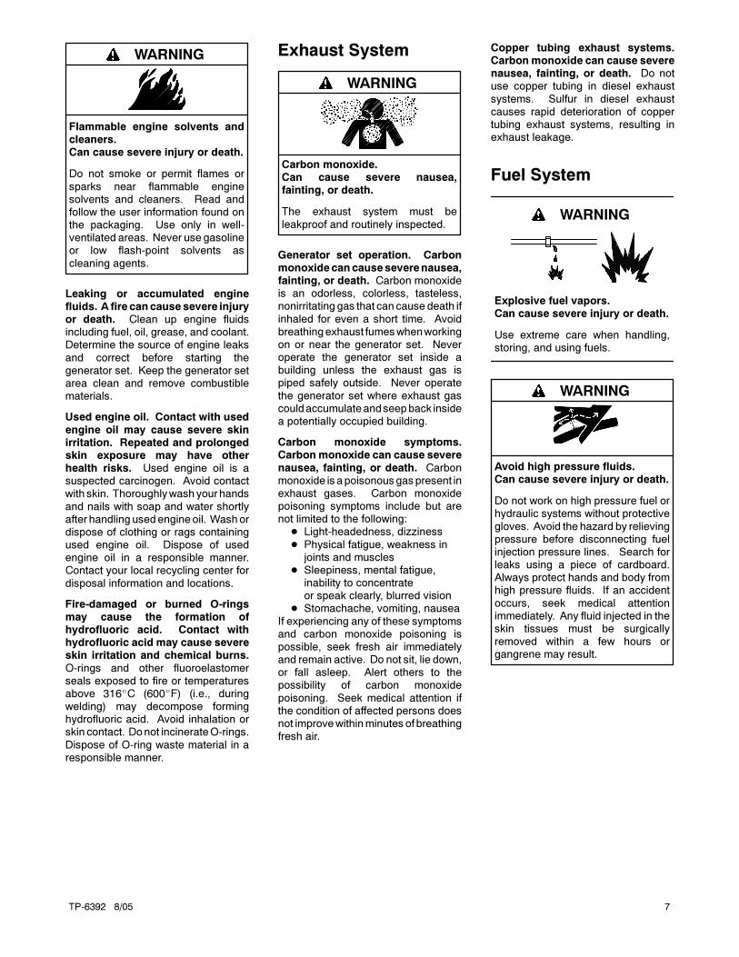
Exhaust System
Carbon monoxide.Can cause severe nausea,fainting, or death.
The exhaust system must be
leakproof and routinely inspected.
WARNING
Generator set operation. Carbonmonoxidecancauseseverenausea,fainting, or death. Carbon monoxideis an odorless, colorless, tasteless,nonirritating gas that can cause death if
inhaled for even a short time. Avoidbreathingexhaust fumeswhenworkingon or near the generator set. Neveroperate the generator set inside abuilding unless the exhaust gas ispiped safely outside. Never operate
the generator set where exhaust gascouldaccumulateandseepback insidea potentially occupied building.
Carbon monoxide symptoms.Carbonmonoxide can cause severe
nausea, fainting, or death. Carbonmonoxide isapoisonousgaspresent inexhaust gases. Carbon monoxidepoisoning symptoms include but arenot limited to the following:
Light-headedness, dizziness
Physical fatigue, weakness injoints and muscles
Sleepiness, mental fatigue,inability to concentrateor speak clearly, blurred vision
Stomachache, vomiting, nausea
If experiencing any of these symptomsand carbon monoxide poisoning ispossible, seek fresh air immediatelyand remain active. Do not sit, lie down,or fall asleep. Alert others to thepossibility of carbon monoxide
poisoning. Seek medical attention ifthe condition of affected persons doesnot improvewithinminutes of breathingfresh air.
Copper tubing exhaust systems.Carbonmonoxide can cause severenausea, fainting, or death. Do notuse copper tubing in diesel exhaust
systems. Sulfur in diesel exhaustcauses rapid deterioration of coppertubing exhaust systems, resulting inexhaust leakage.
Fuel System
Explosive fuel vapors.Can cause severe injury or death.
Use extreme care when handling,storing, and using fuels.
WARNING
Avoid high pressure fluids.Can cause severe injury or death.
Do not work on high pressure fuel orhydraulic systems without protective
gloves. Avoid the hazard by relievingpressure before disconnecting fuelinjection pressure lines. Search forleaks using a piece of cardboard.Always protect hands and body fromhigh pressure fluids. If an accident
occurs, seek medical attentionimmediately. Any fluid injected in theskin tissues must be surgicallyremoved within a few hours organgrene may result.
WARNING

TP-6392 8/058
The fuel system. Explosive fuelvapors can cause severe injury ordeath. Vaporized fuels are highlyexplosive. Use extreme care when
handling and storing fuels. Store fuelsin a well-ventilated area away fromspark-producing equipment and out ofthe reach of children. Never add fuel tothe tank while the engine is runningbecause spilled fuel may ignite on
contact with hot parts or from sparks.Do not smoke or permit flames orsparks to occur near sources of spilledfuel or fuel vapors. Keep the fuel linesand connections tight and in goodcondition. Do not replace flexible fuel
lines with rigid lines. Use flexiblesections to avoid fuel line breakagecausedbyvibration. Donotoperate thegenerator set in the presence of fuelleaks, fuel accumulation, or sparks.Repair fuel systems before resuming
generator set operation.
Fuel tanks. Explosive fuel vaporscan cause severe injury or death.Gasoline and other volatile fuels storedin day tanks or subbase fuel tanks can
cause an explosion. Store only dieselfuel in tanks.
Draining the fuel system. Explosivefuel vapors can cause severe injuryor death. Spilled fuel can cause anexplosion. Useacontainer to catch fuel
whendraining the fuel system. Wipeupspilled fuel after draining the system.
Hazardous Noise
Hazardous noise.Can cause hearing loss.
Never operate the generator setwithout a muffler or with a faulty
exhaust system.
CAUTION
Engine noise. Hazardous noise can
cause hearing loss. Generator setsnot equipped with sound enclosurescan produce noise levels greater than105 dBA. Prolongedexposure tonoiselevels greater than 85 dBA can causepermanent hearing loss. Wear hearing
protection when near an operatinggenerator set.
Hazardous Voltage/Electrical Shock
Hazardous voltage.Can cause severe injury or death.
Operate the generator set only whenall guards and electrical enclosures
are in place.
Moving rotor.
WARNING
Hazardous voltage.Backfeed to the utility system cancause property damage, severeinjury, or death.
If the generator set is used forstandby power, install an automatictransfer switch to prevent inadvertentinterconnection of standby andnormal sources of supply.
WARNING
Welding the generator set.Can cause severe electricalequipment damage.
Never weld components of the
generator set without firstdisconnecting the battery, controllerwiringharness, andengineelectroniccontrol module (ECM).
CAUTION
Grounding electrical equipment.Hazardous voltage can causesevere injury or death. Electrocutionis possible whenever electricity is
present. Open the main circuitbreakers of all power sources beforeservicing theequipment. Configure theinstallation to electrically ground thegenerator set, transfer switch, andrelated equipment and electrical
circuits to complywithapplicablecodesand standards. Never contactelectrical leads or appliances whenstanding in water or on wet groundbecause these conditions increase therisk of electrocution.
Welding on the generator set. Cancause severe electrical equipmentdamage. Before welding on thegenerator set perform the followingsteps: (1) Remove the battery cables,
negative (--) lead first. (2) Disconnectall engine electronic control module(ECM) connectors. (3) Disconnect allgenerator set controller and voltageregulator circuit board connectors.(4) Disconnect the engine battery-
charging alternator connections.(5) Attach the weld ground connectionclose to the weld location.
Installing the battery charger.Hazardous voltage can causesevere injury or death. An
ungrounded battery charger maycause electrical shock. Connect thebatterychargerenclosure to thegroundof a permanent wiring system. As analternative, install an equipmentgrounding conductor with circuit
conductors and connect it to theequipment grounding terminal or thelead on the battery charger. Install thebattery charger as prescribed in theequipment manual. Install the batterycharger in compliance with local codes
and ordinances.
TP-6392 8/05 9
Connecting the battery and thebattery charger. Hazardous voltagecan cause severe injury or death.Reconnect the battery correctly,
positive to positive and negative tonegative, to avoid electrical shock anddamage to the battery charger andbattery(ies). Have a qualifiedelectrician install the battery(ies).
Servicing the day tank. Hazardous
voltage can cause severe injury ordeath. Service the day tank electricalcontrol module (ECM) as prescribed inthe equipmentmanual. Disconnect thepower to the day tank before servicing.
Press the day tank ECM OFFpushbutton to disconnect the power.Notice that line voltage is still presentwithin the ECM when the POWER ONlight is lit. Ensure that the generator setand day tank are electrically grounded.
Do not operate the day tank whenstanding in water or on wet groundbecause these conditions increase therisk of electrocution.
Short circuits. Hazardousvoltage/current can cause severe
injury or death. Short circuits cancause bodily injury and/or equipmentdamage. Do not contact electricalconnections with tools or jewelry whilemaking adjustments or repairs.Removeall jewelrybefore servicing the
equipment.
Engine block heater. Hazardousvoltage can cause severe injury ordeath. The engine block heater cancause electrical shock. Remove theengine block heater plug from the
electrical outlet before working on theblock heater electrical connections.
Electrical backfeed to the utility.Hazardous backfeed voltage cancause severe injury or death. Install
a transfer switch in standby powerinstallations to prevent the connectionof standby and other sources of power.Electrical backfeed into a utilityelectrical system can cause severeinjury or death to utility personnel
working on power lines.
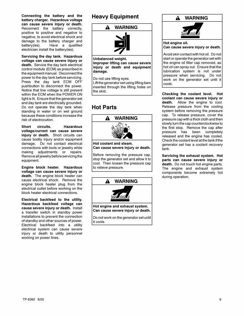
Heavy Equipment
Unbalanced weight.Improper lifting can cause severeinjury or death and equipmentdamage.
Do not use lifting eyes.Lift the generator set using lifting barsinserted through the lifting holes onthe skid.
WARNING
Hot Parts
Hot coolant and steam.Can cause severe injury or death.
Before removing the pressure cap,stop the generator set and allow it to
cool. Then loosen the pressure capto relieve pressure.
WARNING
Hot engine and exhaust system.Can cause severe injury or death.
Do not work on the generator set untilit cools.
WARNING
Hot engine oil.Can cause severe injury or death.
Avoid skin contact with hot oil. Do notstart or operate thegenerator setwith
the engine oil filler cap removed, ashot oil can spray out. Ensure that thelubrication system is not underpressure when servicing. Do notwork on the generator set until itcools.
WARNING
Checking the coolant level. Hotcoolant can cause severe injury ordeath. Allow the engine to cool.Release pressure from the coolingsystem before removing the pressure
cap. To release pressure, cover thepressure capwith a thick cloth and thenslowly turn the cap counterclockwise tothe first stop. Remove the cap afterpressure has been completely
released and the engine has cooled.Check the coolant level at the tank if thegenerator set has a coolant recoverytank.
Servicing the exhaust system. Hotparts can cause severe injury or
death. Do not touch hot engine parts.The engine and exhaust systemcomponents become extremely hotduring operation.

TP-6392 8/0510
Moving Parts
Hazardous voltage.Can cause severe injury or death.
Operate the generator set only whenall guards and electrical enclosures
are in place.
Moving rotor.
WARNING
Rotating parts.Can cause severe injury or death.
Operate the generator set only whenall guards, screens, and covers are in
place.
WARNING
Airborne particles.Can cause severe injury orblindness.
Wear protective goggles and clothing
when using power tools, hand tools,or compressed air.
WARNING
Tightening the hardware. Flyingprojectiles can cause severe injuryor death. Loose hardware can causethe hardware or pulley to release from
thegeneratorsetengineandcancausepersonal injury. Retorque allcrankshaft and rotor hardware afterservicing. Donot loosen thecrankshafthardwareor rotor thrubolt whenmakingadjustments or servicing the generator
set. Rotate the crankshaft manually ina clockwise direction only. Turning thecrankshaft bolt or rotor thruboltcounterclockwise can loosen thehardware.
Servicing the generator set when itis operating. Exposedmoving partscan cause severe injury or death.Keep hands, feet, hair, clothing, andtest leads away from the belts andpulleys when the generator set is
running. Replaceguards, screens,andcovers before operating the generatorset.
Notice
NOTICE
This generator set has beenrewired from its nameplate voltageto
246242
NOTICE
Voltage reconnection. Affix a noticeto the generator set after reconnectingthe set to a voltage different from thevoltage on the nameplate. Ordervoltage reconnection decal 246242from an authorized service
distributor/dealer.
NOTICE
Hardware damage. The engine andgenerator set may use both American
Standard and metric hardware. Usethe correct size tools to preventrounding of the bolt heads and nuts.
NOTICE
When replacing hardware, do notsubstitute with inferior gradehardware. Screws and nuts areavailable in different hardness ratings.To indicate hardness, AmericanStandard hardware uses a series of
markings, and metric hardware uses anumeric system. Check the markingson the bolt heads and nuts foridentification.
NOTICE
Canadian installations only. Forstandby service connect the output ofthe generator set to a suitably ratedtransfer switch in accordance with
Canadian Electrical Code, Part 1.

TP-6392 8/05 Introduction 11
Introduction
This manual provides operation instructions for Model
10/15/20REOD/REOZD generator sets.
Refer to the engine operation manual for generator set
engine scheduled maintenance information.
Information in this publication represents data available
at the time of print. Kohler Co. reserves the right to
change this publication and the products represented
without notice and without any obligation or liability
whatsoever.
Read this manual and carefully follow all procedures
and safety precautions to ensure proper equipment
operation and to avoid bodily injury. Read and follow the
Safety Precautions and Instructions section at the
beginning of this manual. Keep this manual with the
equipment for future reference.
The equipment service requirements are very important
to safe and efficient operation. Inspect the parts often
and perform required service at the prescribed intervals.
Obtain service from an authorized service
distributor/dealer to keep equipment in top condition.
List of Related Literature
Figure 1 identifies related literature available for the
generator sets covered in this manual. Only trained and
qualified personnel should install or service the
generator set.
Literature Type Part Number
Installation Manual TP-6393
Operation Manual (Generator) TP-6392
Operation Manual (Engine) TP-6412
Parts Catalog* TP-6395
Service Manual (Generator) TBD
Service Manual (Engine) TP-6293
* One manual combines Generator and Engine information.
Figure 1 Generator Set Literature
x:in:001:005
Maintenance and Service Parts
Figure 2 identifies maintenance and service parts for
your generator set. Obtain a complete list of
maintenance and service parts from your authorized
generator distributor/dealer.
Part Description Part Number
Air Cleaner Element for:
10REOD/REOZD
15REOD/REOZD
GM42265
Air Cleaner Element for:
20REOD/REOZDGM42266
Belt GM42428
Fuel Filter Element GM32359
Fuel/Water Separator Element 225259
Fuse, Auxiliary Winding (F1):
20 amp for 12 lead generator sets GM39266
10 amp for 4 lead generator sets 223316
Fuse, Relay Interface Board (F2) 10 amp 223316
Fuse, Controller (F3) 10 amp 223316
Oil Filter 252834
Spray Paint (Black) 221292
Figure 2 Maintenance and Service Parts
x:in:001:004

TP-6392 8/0512 Introduction
Service Assistance
For professional advice on generator power
requirements and conscientious service, please contact
your nearest Kohler distributor or dealer.
Consult the Yellow Pages under the heading
Generators—Electric
Visit the Kohler Power Systems website at
KohlerPowerSystems.com
Look at the labels and stickers on your Kohler product
or review the appropriate literature or documents
included with the product
Call toll free in the US and Canada 1-800-544-2444
Outside the US andCanada, call the nearest regional
office
Headquarters Europe, Middle East, Africa
(EMEA)
Kohler Power Systems
ZI Senia 122
12, rue des Hauts Flouviers
94517 Thiais Cedex
France
Phone: (33) 1 41 735500
Fax: (33) 1 41 735501
Asia Pacific
Power Systems Asia Pacific Regional Office
Singapore, Republic of Singapore
Phone: (65) 6264-6422
Fax: (65) 6264-6455
China
North China Regional Office, Beijing
Phone: (86) 10 6518 7950
(86) 10 6518 7951
(86) 10 6518 7952
Fax: (86) 10 6518 7955
East China Regional Office, Shanghai
Phone: (86) 21 6288 0500
Fax: (86) 21 6288 0550
India, Bangladesh, Sri Lanka
India Regional Office
Bangalore, India
Phone: (91) 80 3366208
(91) 80 3366231
Fax: (91) 80 3315972
Japan, Korea
North Asia Regional Office
Tokyo, Japan
Phone: (813) 3440-4515
Fax: (813) 3440-2727
Latin America
Latin America Regional Office
Lakeland, Florida, USA
Phone: (863) 619-7568
Fax: (863) 701-7131
TP-6392 8/05 13Section 1 Features
Section 1 Features
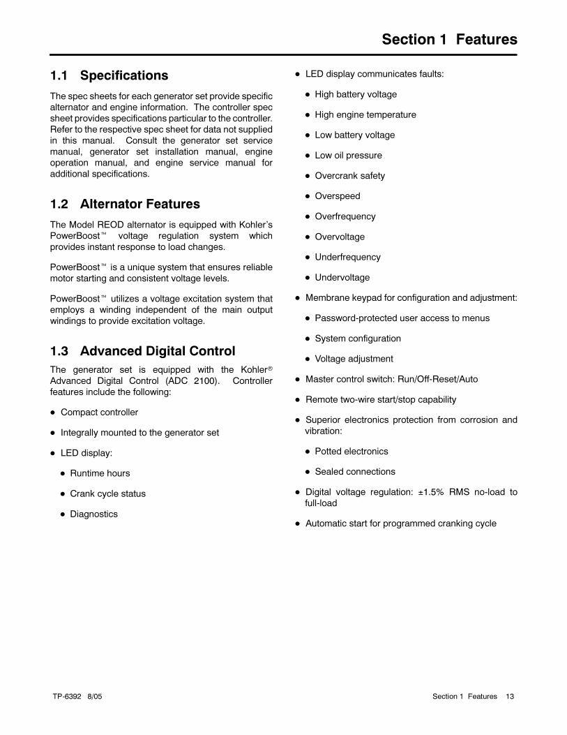
1.1 Specifications
The spec sheets for each generator set provide specific
alternator and engine information. The controller spec
sheet provides specifications particular to the controller.
Refer to the respective spec sheet for data not supplied
in this manual. Consult the generator set service
manual, generator set installation manual, engine
operation manual, and engine service manual for
additional specifications.
1.2 Alternator Features
The Model REOD alternator is equipped with Kohler’s
PowerBoost voltage regulation system which
provides instant response to load changes.
PowerBoost is a unique system that ensures reliable
motor starting and consistent voltage levels.
PowerBoost utilizes a voltage excitation system that
employs a winding independent of the main output
windings to provide excitation voltage.
1.3 Advanced Digital Control
The generator set is equipped with the Kohler
Advanced Digital Control (ADC 2100). Controller
features include the following:
Compact controller
Integrally mounted to the generator set
LED display:
Runtime hours
Crank cycle status
Diagnostics
LED display communicates faults:
High battery voltage
High engine temperature
Low battery voltage
Low oil pressure
Overcrank safety
Overspeed
Overfrequency
Overvoltage
Underfrequency
Undervoltage
Membrane keypad for configuration and adjustment:
Password-protected user access to menus
System configuration
Voltage adjustment
Master control switch: Run/Off-Reset/Auto
Remote two-wire start/stop capability
Superior electronics protection from corrosion and
vibration:
Potted electronics
Sealed connections
Digital voltage regulation: ±1.5% RMS no-load to
full-load
Automatic start for programmed cranking cycle

TP-6392 8/0514 Section 1 Features
Notes

TP-6392 8/05 15Section 2 Operation
Section 2 Operation
2.1 Prestart Checklist
To ensure continued satisfactory operation perform the
following checks or inspections before or at each
startup, as designated, and at the intervals specified in
the service schedule. In addition, some checks require
verification after the unit starts.
Air Cleaner. Check for a clean air cleaner element to
prevent unfiltered air from entering the engine.
Air Inlets. Check for clean and unobstructed air inlets.
Air Shrouding. Check for securely installed and
positioned air shrouding.
Battery. Check for tight battery connections. Consult
the battery manufacturer’s instructions regarding
battery care and maintenance.
Coolant Level. Check the coolant level according to
the cooling system maintenance information.
Note: Block heater damage. The block heater will fail
if the energized heater element is not immersed
in coolant. Fill the cooling system before turning
on the block heater. Run the engine until it is
warm, and refill the radiator to purge the air from
the system before energizing the block heater.
Drive Belt(s). Check the belt condition and tension of
the water pump and battery charging alternator belt(s).
Exhaust System. Check for exhaust leaks and
blockages. Check the muffler and piping condition and
check for tight exhaust system connections.
Inspect the exhaust system components for cracks and
corrosion (exhaust manifold, exhaust line, exhaust
clamps, and muffler).
Check for corroded or brokenmetal parts and replace
them as needed.
Check for loose, corroded, or missing clamps and
hangers. Tighten or replace the exhaust clamps
and/or hangers as needed.
Check that the exhaust outlet is unobstructed.
Visually inspect for exhaust leaks (blowby). Check
for carbon or soot residue on exhaust components.
Carbon and soot residue indicates an exhaust leak.
Seal leaks as needed.
Fuel Level. Check the fuel level and keep the tank(s)
full to ensure adequate fuel supply.
Oil Level. Maintain the oil level at or near, not over, the
full mark on the dipstick.
Operating Area. Check for obstructions that could
block the flow of cooling air. Keep the air intake area
clean. Do not leave rags, tools, or debris on or near the
generator set.
2.2 Exercising the Generator Set
Operate the generator set without load once each week
for 20 minutes. If the generator set does not have a
programmed exercise mode or an automatic transfer
switch (ATS) with an exercise option, exercise the unit in
the presence of an operator.
The operator should perform all of the prestart checks
before starting the exercise procedure. Start the
generator set according to the starting procedure in
Section 2.3.2 of this manual. While the generator set is
operating, listen for a smooth-running engine and
visually inspect the generator set for fluid or exhaust
leaks. Check the air inlets and outlets and remove any
items restricting the air flow.

TP-6392 8/0516 Section 2 Operation
2.3 Generator Set Operation
Figure 2-1 illustrates the user interface on theAdvanced
Digital Control (ADC 2100) generator set controller.
GM28707A-C
1. LED display2. Select button3. Upanddownarrowbuttons (use for setupandadjustmentonly)4. Generator set master switch
1
2
4
3
Figure 2-1 ADC 2100 User Interface
2.3.1 ADC 2100 Controls and Indicators
Figure 2-2 describes the controls and indicators located
on the ADC 2100.
The LED display indicates generator set status. The
LED display is activated when the generator set master
switch is moved to the RUN or AUTO position and
remains active until the master switch is moved to the
OFF/RESET position or power to the controller is
removed. The LED display turns off 48 hours after
generator set shutdown. See Section 2.3.6.
The buttons on the controller keypad are used only for
system configuration and adjustment. The system
configuration is factory-set and should not require
changes under normal operating conditions. Contact an
authorized distributor/dealer or service technician if
adjustments are required.
2.3.2 Local Operation
Local Starting
Move the generator set master switch to the RUN
position to start the generator set.
The controller attempts to start the generator set three
times (three crank cycles, 15 seconds crank and
15 seconds off). If the generator set does not start in
three attempts, the system shuts down on an overcrank
fault.
Local Stopping
1. Run the generator set at no load for at least
2 minutes to ensure adequate engine cooldown.
2. Move the generator set master switch to the
OFF/RESET position. The engine stops.
Note: There is no engine cooldown time delay on the
ADC 2100 controller.
Control or Indicator Item Description
LED display Runtime hours Displays total generator set runtime hours while the generator set is running and when noother codes are displayed.
Crank indication Displays CC_1, CC_2, or CC_3 to indicate the first, second, or third attempt to start theengine. The last digit flashes during the crank cycle rest periods.
Fault codes Flashes a 2- or 3-letter fault code to indicate various fault conditions. See Section 2.3.4.
Fuel Displays FUEL during fuel pump priming procedure. See Section 3.5.4.
Software versionnumber
See Section 2.3.7.
Keypad Select and arrowbuttons
The keypad is used for controller setup and adjustment only. Have setup and adjustmentsperformed only by an authorized distributor/dealer. The setup and adjustment functions arepassword-protected.
Generator set masterswitch
Three-positionswitch
Switch functions as the generator set operation and controller reset switch.
Figure 2-2 ADC 2100 Controls and Indicators

TP-6392 8/05 17Section 2 Operation
2.3.3 Remote/Automatic Operation
A remote switch or an automatic transfer switch (ATS)
can be used to start and stop the generator set.
Connect the remote start/stop switch or the ATS engine
start contacts to ADC 2100 engine start leads 3 and 4.
Move the generator set master switch to the AUTO
position.
Automatic Starting
With the generator set master switch in the AUTO
position, close the remote start contact connected to
engine start leads 3 and 4 to signal the generator set to
start.
The controller attempts to start the generator set three
times (three crank cycles, 15 seconds crank and
15 seconds off). If the generator set does not start in
three attempts, the system shuts down on an overcrank
fault.
Automatic Stopping
With the generator set master switch in the AUTO
position, open the remote switch or contact to stop the
generator set.
If the generator set was started by a start signal from a
remote start/stop switch or ATS, moving the generator
set master switch on the ADC 2100 to the OFF/RESET
position also stops the generator set.
Note: There is no engine cooldown time delay on the
ADC 2100 controller.
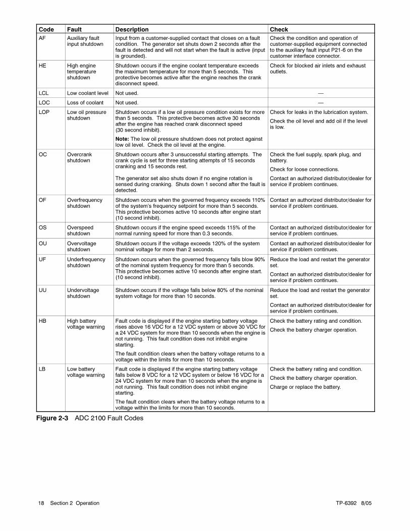
2.3.4 Faults
Figure 2-3 lists fault codes displayed by the ADC 2100.
If the generator set shuts down on a fault condition, it
cannot be restarted until the fault condition is corrected
and the controller is reset. SeeSection 2.3.5 to reset the
controller after a fault shutdown. The controller resets
automatically after a battery voltage fault condition is
corrected.
The shutdown switches on the generator set
automatically reset when the problem is corrected. The
high engine temperature switch automatically resets
when the generator set cools. However, the fault does
not clear until the controller is reset.
The controller displays a fault code but the generator set
does not shut down under the high and low battery
voltage warning conditions.
2.3.5 Resetting the Controller after a
Fault Shutdown
Always identify and correct the cause of a fault
shutdown before resetting the controller. Use the
following procedure to reset the generator set controller
after a fault shutdown.
1. Move the generator set master switch to
OFF/RESET.
2. Disconnect the generator set from the load using
the line circuit breaker or ATS. See the safety
precautions at the beginning of this section before
proceeding.
3. Identify and correct the cause of the fault
shutdown. See the safety precautions at the
beginning of this section before proceeding. Refer
to Section 4, Troubleshooting.
4. Start the generator set bymoving the generator set
master switch to RUN. Test operate the generator
set to verify that the cause of the shutdown has
been corrected.
5. Move the generator set master switch to
OFF/RESET.
6. Reconnect the generator set to the load using the
line circuit breaker or ATS.
7. Move the generator set master switch to the AUTO
position for startup by remote transfer switch or
remote start/stop switch.
Note: The controller’s LED display remains off
until an engine start command is received.
Opening and closing a remote start/stop contact also
resets the controller.
TP-6392 8/0518 Section 2 Operation
Code Fault Description Check
AF Auxiliary faultinput shutdown
Input from a customer-supplied contact that closes on a faultcondition. The generator set shuts down 2 seconds after thefault is detected and will not start when the fault is active (inputis grounded).
Check the condition and operation ofcustomer-supplied equipment connectedto the auxiliary fault input P21-6 on thecustomer interface connector.
HE High enginetemperatureshutdown
Shutdown occurs if the engine coolant temperature exceedsthe maximum temperature for more than 5 seconds. Thisprotective becomes active after the engine reaches the crankdisconnect speed.
Check for blocked air inlets and exhaustoutlets.
LCL Low coolant level Not used. —
LOC Loss of coolant Not used. —
LOP Low oil pressureshutdown
Shutdown occurs if a low oil pressure condition exists for morethan 5 seconds. This protective becomes active 30 secondsafter the engine has reached crank disconnect speed(30 second inhibit).
Note: The low oil pressure shutdown does not protect againstlow oil level. Check the oil level at the engine.
Check for leaks in the lubrication system.
Check the oil level and add oil if the levelis low.
OC Overcrankshutdown
Shutdown occurs after 3 unsuccessful starting attempts. Thecrank cycle is set for three starting attempts of 15 secondscranking and 15 seconds rest.
The generator set also shuts down if no engine rotation issensed during cranking. Shuts down 1 second after the fault isdetected.
Check the fuel supply, spark plug, andbattery.
Check for loose connections.
Contact an authorized distributor/dealer forservice if problem continues.
OF Overfrequencyshutdown
Shutdown occurs when the governed frequency exceeds 110%of the system’s frequency setpoint for more than 5 seconds.This protective becomes active 10 seconds after engine start(10 second inhibit).
Contact an authorized distributor/dealer forservice if problem continues.
OS Overspeedshutdown
Shutdown occurs if the engine speed exceeds 115% of thenormal running speed for more than 0.3 seconds.
Contact an authorized distributor/dealer forservice if problem continues.
OU Overvoltageshutdown
Shutdown occurs if the voltage exceeds 120% of the systemnominal voltage for more than 2 seconds.
Contact an authorized distributor/dealer forservice if problem continues.
UF Underfrequencyshutdown
Shutdown occurs when the governed frequency falls blow 90%of the nominal system frequency for more than 5 seconds.This protective becomes active 10 seconds after engine start.(10 second inhibit).
Reduce the load and restart the generatorset.
Contact an authorized distributor/dealer forservice if problem continues.
UU Undervoltageshutdown
Shutdown occurs if the voltage falls below 80% of the nominalsystem voltage for more than 10 seconds.
Reduce the load and restart the generatorset.
Contact an authorized distributor/dealer forservice if problem continues.
HB High batteryvoltage warning
Fault code is displayed if the engine starting battery voltagerises above 16 VDC for a 12 VDC system or above 30 VDC fora 24 VDC system for more than 10 seconds when the engine isnot running. This fault condition does not inhibit enginestarting.
The fault condition clears when the battery voltage returns to avoltage within the limits for more than 10 seconds.
Check the battery rating and condition.
Check the battery charger operation.
LB Low batteryvoltage warning
Fault code is displayed if the engine starting battery voltagefalls below 8 VDC for a 12 VDC system or below 16 VDC for a24 VDC system for more than 10 seconds when the engine isnot running. This fault condition does not inhibit enginestarting.
The fault condition clears when the battery voltage returns to avoltage within the limits for more than 10 seconds.
Check the battery rating and condition.
Check the battery charger operation.
Charge or replace the battery.
Figure 2-3 ADC 2100 Fault Codes

TP-6392 8/05 19Section 2 Operation
2.3.6 Power Down
The controller is powered by the generator set engine
starting battery.
If the ADC 2100 is not configured for the optional
Remote Digital Gauge (communication setting Cn00),
the controller powers down after 48 hours of no activity
when the master switch is in the AUTO position. (See
the Installation Manual for more information about ADC
2100 controller settings.) A start signal from a remote
start/stop switch or a transfer switch connected to
engine start leads 3 and 4 energizes the controller and
initiates the crank cycle. Moving the generator set
master switch to the RUN position also turns the
controller back on.
If the ADC 2100 is configured for the optional Remote
Digital Gauge (communications setting Cn01), the
controller remains active at all times when the generator
set master switch is in the AUTO position.
Note: The ADC 2100 consumes 250 mA when the
master switch is in the AUTO position with the
Remote Digital Gauge connected. Exercise the
generator set weekly and consider using a
battery charger to maintain the battery.
2.3.7 Controller Software Version
Number
The application software for controller operation is
factory-loaded onto the Advanced Digital Control. At
times, itmay be necessary to check the software version
number for troubleshooting purposes. Use the following
procedure.
Displaying the Software Version Number
1. Press and hold the Select button on the ADC
2100.
2. Move the generator set master switch to the Run
postion. The generator set will not start.
3. After approximately five seconds, the software
version number is shown on the ADC 2100 display.
For example, 01.18 will be displayed for software
version 1.18.
4. Move the generator set master switch to the
OFF/RESET position and release the Select
button.
2.4 Circuit Protection
If the generator set circuit breaker trips or the fuses blow
repeatedly, see Section 4, Troubleshooting, for possible
causes.
2.4.1 Line Circuit Breaker
A circuit breaker interrupts the generator output in the
event of a fault in the wiring between the generator and
the load. The line circuit breaker location is shown in
Figure 3-1. If the circuit breaker trips, reduce the load
and switch the breaker back to the ON position.
2.4.2 Fuses
The junction box contains three inline fuses. Always
identify and correct the cause of a blown fuse before
restarting the generator set. Refer to section 4,
Troubleshooting, for conditions that may indicate a
blown fuse. Obtain service from an authorized
distributor/dealer.
Controller Fuse. A replaceable 10-amp fuse protects
the controller circuitry. If the controller display is dark,
check the battery and battery connections and then
check the controller fuse. Replace the fuse if it is blown.
Relay Fuse. A replaceable 10-amp fuse protects the
engine relays. If the generator set does not crank, check
the battery and battery connections and then check the
relay fuse. Replace the fuse if it is blown.
Auxiliary Winding Fuse. A replaceable 10-amp fuse
for 4 lead generator sets (20-amp fuse for 12 lead
generator sets) protects the alternator.

TP-6392 8/0520 Section 2 Operation
Notes

TP-6392 8/05 21Section 3 Scheduled Maintenance
Section 3 Scheduled Maintenance
3.1 General Maintenance
Accidental starting.Can cause severe injury or death.
Disconnect the battery cables beforeworking on the generator set.
Remove the negative (--) lead firstwhen disconnecting the battery.Reconnect the negative (--) lead lastwhen reconnecting the battery.
WARNING
Disabling the generator set. Accidental starting cancause severe injury or death. Before working on thegenerator set or connected equipment, disable the generator
set as follows: (1) Move thegenerator setmaster switch to theOFFposition. (2) Disconnect thepower to thebattery charger.(3) Remove the battery cables, negative (--) lead first.Reconnect the negative (--) lead last when reconnecting thebattery. Follow these precautions to prevent starting of thegenerator set by an automatic transfer switch, remote
start/stop switch, or engine start command from a remotecomputer.
Rotating parts.
Can cause severe injury or death.
Operate the generator set only when
all guards, screens, and covers are in
place.
WARNING
Servicing thegenerator setwhen it is operating. Exposedmoving parts can cause severe injury or death. Keephands, feet, hair, clothing, and test leads away from the beltsand pulleys when the generator set is running. Replaceguards, screens, and covers before operating the generator
set.
NOTICE
Hardware damage. The engine and generator set may usebothAmericanStandardandmetrichardware. Use thecorrectsize tools to prevent rounding of the bolt heads and nuts.
See the Safety Precautions and Instructions at the
beginning of this manual before attempting to service,
repair, or operate the generator set. Have an authorized
distributor/dealer perform generator set service.
Engine Service. Perform generator set engine service
at the intervals specified by the engine operation
manual.
Generator Set Exercise. Operate the generator set
without load once each week for 20 minutes. If the
transfer switch does not have an exercise option,
exercise the unit in the presence of an operator.
Generator Set Service. Perform generator set service
at the intervals specified by the generator set operation
manual.
If the generator set operates under dusty or dirty
conditions, use dry compressed air to blow dust out of
the alternator. With the generator set running, direct the
stream of air in through the cooling slots at the alternator
end.
RoutineMaintenance. Refer to the following generator
set service schedule, the engine service schedule, and
the runtime hours shown on the ADC 2100 to determine
when to schedule routine maintenance. Service more
frequently generator sets that are subject to extreme
weather or dusty or dirty conditions.
Service Log. Use the Operating Hour Service Log
located in the back of this manual to document
performed services.
Service Schedule. Performmaintenance on each item
in the service schedule at the designated intervals for
the life of the generator set. For example, an item
requiring service every 100 hours or 3 months also
requires service after 200 hours or 6 months, 300 hours
or 9 months, and so on.

TP-6392 8/0522 Section 3 Scheduled Maintenance
3.2 Service Schedule
Procedure ReferenceSystem—Component Check Change Clean Test
ReferenceSection
FUEL
Day tank level W
Flexible lines and connections W R
Main tank supply level W
Fuel/water separator M (drain) S 3.5
Filter(s) Q 3.5
Drain tank and replace fuel 50 or M
Fuel piping Q
Tank vents and return lines for obstructions Q
Fuel injection system Y Y Eng. S/M
LUBRICATION
Oil level W 3.4
Crankcase breather 1500 Eng. S/M
Change oil First 50, 3.4
Replace filter(s)*
First 50,then 250 3.4
COOLING
Block heater operation W
Coolant level W 3.8
Flexible hoses and connectors W
Water pump(s) W
Fan and alternator belts M R 3.9
Air ducts, louvers * Y Y
Louver motors and controls Y Y Y
Radiator exterior * Y 3.8
EXHAUST SYSTEM
Drain condensate trap W I/M
Leakage W 3.7
Insulation, fire hazards Q 3.7
Flexible connector(s) W 3.7
Excessive back pressure Y I/M
Hangers and supports Y 3.7
DC ELECTRICAL SYSTEM
Battery charger operation, charge rate M Batterycharger
Recharge after engine start Mcharger
instructions
Battery electrolyte level M Batteryf ’Battery specific gravity, charge state M
ymanufacturer’sinstructions
Remove corrosion, clean and dry battery and rack S Sinstructions
Clean and tighten battery terminals Q
Tighten DC electrical connections S
* Service more frequently if operated in dusty areas.
Consult your local distributor/dealer for service.
Do not break manufacturer’s seals or internally inspect thesedevices.
D: Daily, before operation
Y: Yearly
2Y: Every 2 years or 2000 hours
R: Replace as necessary
Number: Hours of operation
W: Weekly
M: Monthly
Q: Quarterly
S: Six months

TP-6392 8/05 23Section 3 Scheduled Maintenance
ProcedureReference
System—Component Check Change Clean TestReferenceSection
AC ELECTRICAL SYSTEM
General Inspection W
Circuit breakers, fuses M R M M
Wire abrasions where subject to motion Q
Tighten control and power wiring connections Y
Wire-cable insulation breakdown 3Y or 500 3Y or 500
ENGINE AND MOUNTING
General inspection (check for leaks) W
Air cleaner service * S S 3.6
Valve clearance 3 Y or 500 Eng. S/M
Bolt torque 3 Y or 500 3 Y or 500 Eng. S/M
REMOTE CONTROL SYSTEM, ETC.
Compartment condition * W W
Remote control M
GENERATOR
General inspection W
Rotor and stator Y Y S/M
Bearing condition Y R S/M
Exciter Y X S/M
Measure and record resistance readings of windings withinsulation tester (Megger, with SCR assembly or rectifierdisconnected)
Y S/M
Blow dust out of generator* 2 Y or 300 2 Y or 300 3.1
GENERAL CONDITION OF EQUIPMENTAny condition of vibration, leakage, unusual noise,temperature, or deterioration
W W
Run generator set (exercise) W 2.2, 2.3
Ensure that system is set for automatic operation W 2.3
Interior of equipment room or outdoor weather housing * W W
* Service more frequently if operated in dusty areas.
Consult your local distributor/dealer for service.
Do not break manufacturer’s seals or internally inspect thesedevices.
D: Daily, before operation
Y: Yearly
2Y: Every 2 years or 2000 hours
R: Replace as necessary
Number: Hours of operation
W: Weekly
M: Monthly
Q: Quarterly
S: Six months

TP-6392 8/0524 Section 3 Scheduled Maintenance
3.3 Service Views
1. Fuses (F1, F2, and F3)2. Advanced Digital Control (ADC 2100)3. Alternator cooling air inlet4. Run-Off/Reset-Auto switch5. Runtime hour display6. Air intake silencer/cleaner7. Fuel inlet connection8. Fuel/water separator9. Lifting eye
10. Fuel return connection11. Fuel filter12. Oil fill (engine top)13. Mechanical governor14. Coolant overflow tube15. Pressure cap (at radiator)
16. Oil fill (front gear cover)17. Radiator18. V-belt19. Oil check/dipstick20. Coolant overflow bottle21. Lube oil filter22. Oil drain23. Fuel feed pump24. Nameplate25. Circuit breaker location26. Remote customer interface connector27. Load lead connection28. Water inlet connection29. Water outlet connection30. Exhaust outlet
1
12
22 2126
19
3
23
1613
27
119
ADV7031-A
2
28
64 5
Engine-End View(With Radiator Removed)
Service-Side View
18
2425
8 14 15
17
20
29 30
7 10
Figure 3-1 Service Views

TP-6392 8/05 25Section 3 Scheduled Maintenance
3.4 Lubrication System
See Figure 3-1 for the oil drain, oil check, oil fill, and oil
filter locations.
Handlingcaustic engine fluidsandchemical products.Can cause severe chemical burns,nausea, fainting, or death.
Most chemicals such as used engineoil, antifreeze/coolant, rustproofingagent, inhibiting oil, degreasingagent, spraypaint, andadhesivesarehazardous tohealth. Readand followthe user information found on the
packaging. Avoid inhalation and skincontact. Use only in well-ventilatedareas and use a protective maskwhen spraying. Store engine fluidsand chemical products in a lockedcabinet. Contact your local recycling
center for disposal information andlocations.
WARNING
Used engine oil. Contact with used engine oil may cause
severe skin irritation. Repeated and prolonged skinexposuremay have other health risks. Used engine oil is asuspected carcinogen. Avoid contact with skin. Thoroughlywash your hands and nails with soap and water shortly afterhandling used engine oil. Wash or dispose of clothing or ragscontaining used engine oil. Dispose of used engine oil in a
responsible manner. Contact your local recycling center fordisposal information and locations.
3.4.1 Oil Specifications
Use oil that meets the American Petroleum Institute
(API) classification of CD or CF. Using an unsuitable oil
or neglecting an oil change may result in damage and a
shorter engine life. Figure 3-2 shows the recommended
Society of Automotive Engineers (SAE) viscosity
designation for given operating temperature ranges.
Note: Failure to observe the oil specifications may
cause inadequate lubrication/oil pressure and
cold-starting difficulties.
°C
°F
--30 --20 --10 0 10 20 30 40
0 20 40 60 80 100
°C
°F
10W
20W
10W30
#20
#30
#40
TP-5856-1
SAE
Service
Grade
Operating Temperature
15W40
Figure 3-2 Engine Oil Selection
3.4.2 Oil Check
Check the oil level in the crankcase daily or before each
startup to ensure that the level is in the safe range. To
check the oil level, remove the dipstick and wipe the end
clean, reinsert as far as possible, and remove. Maintain
the oil level between the Min and Max marks on the
dipstick, as shown in Figure 3-3. See Figure 3-1 for
dipstick location.
Note: Do not operate the set if the oil level is below the
Min mark or above the Max mark.
1-933
1 2
1. Max level2. Min level
Figure 3-3 Oil Level Check

TP-6392 8/0526 Section 3 Scheduled Maintenance
3.4.3 Oil Change
See the Service Schedule in Section 3.2 for oil change
and oil filter replacement intervals. Change the oil more
frequently if the generator operates under dirty, dusty
conditions. See Figure 3-4 for oil capacities.
Model L (Qts.)
10REOD/REOZD 3.6 (3.8)
15REOD/REOZD 4.7 (5.0)
20REOD/REOZD 5.8 (6.1)
Figure 3-4 Oil Capacities
Oil Change Procedure
Whenever possible, drain the oil while it is still warm.
1. Drain the oil.
a. Place the generator set master switch in the
OFF position.
b. Disconnect the power to the battery charger, if
equipped.
c. Disconnect the generator set engine starting
battery, negative (--) lead first.
d. Place an oil collection container below the oil
drain and remove the oil drain plug.
e. Allow time for the engine oil to drain completely.
f. Replace the oil drain plug.
2. Replace the oil filter.
a. Remove the oil filter by rotating it
counterclockwise with an oil filter wrench.
b. Apply a light coat of clean oil to the rubber seal
of the new oil filter.
c. Install the new oil filter following the instructions
provided with the filter.
Note: Dispose of all waste materials (engine
oil, fuel, filter, etc.) in an environmentally
safe manner.
3. Fill with oil. Add new oil of the weight, grade, and
quantity specified in Section 3.4.
4. Check for leaks.
a. Check that the generator set master switch is in
the OFF position.
b. Reconnect the generator set engine starting
battery, negative (--) lead last.
c. Reconnect the power to the battery charger, if
equipped.
d. Start the generator set and check for leaks
around the oil filter.
e. Stop the generator set and tighten the oil filter to
stop any leaks.
x:sm:001:003:

TP-6392 8/05 27Section 3 Scheduled Maintenance
3.5 Fuel System
Explosive fuel vapors.Can cause severe injury or death.
Use extreme care when handling,storing, and using fuels.
WARNING
Fuel tanks. Explosive fuel vaporscancausesevere injuryor death. Gasoline andother volatile fuels stored in day tanksor subbase fuel tanks can cause an explosion. Store only
diesel fuel in tanks.
Draining the fuel system. Explosive fuel vapors cancause severe injury or death. Spilled fuel can cause anexplosion. Usea container to catch fuelwhendraining the fuelsystem. Wipe up spilled fuel after draining the system.
3.5.1 Fuel Specifications
Use a clean, good quality diesel fuel oil with a cetane
number of 45 or greater. Clean fuel prevents the diesel
fuel injectors and pumps from clogging.
Fuel Recommendations
United States ISO 8217 DMA, BS 2869 A1 or A2
United Kingdom BS 2869-1983, Part 2 Class A2
Germany DIN 51 601-1978
Japan JIS. No. K2204-2
Note: Never store diesel fuel in galvanized containers;
diesel fuel and the galvanized coating react
chemically to produce flaking that quickly clogs
filters or causes fuel pump or injector failure.
Note: Avoid storing fuel for more than onemonth. Take
special precautions to keep all dirt, water, and
other contaminants out of fuel to prevent the
growth of microbes. Microbes form slime that
clogs the fuel filter and lines.
Note: Do not run the generator set out of fuel because
the fuel lines will draw in air and necessitate
priming the fuel system before restarting the unit.
3.5.2 Fuel Filter
The quality and condition of the fuel largely determine
the filter’s useful life. Replace the fuel filter element as
listed in the service schedule. Figure 3-1 shows the
typical location of a fuel filter. Use the applicable
procedure below to replace the fuel filter.
Fuel Filter Cleaning/Replacement Procedure
1. Close the fuel supply valve.
2. Loosen the fuel filter by turning it counterclockwise.
Remove the fuel filter and use rags to clean up
spilled fuel oil. Dispose of the fuel filter in an
approved manner.
3. Clean the contact surface of the fuel oil filter
adapter.
4. Lightly lubricate the gasket surface of the new fuel
filter with fresh fuel oil. Thread the filter on the
adapter until the gasket makes contact;
hand-tighten the filter an additional one-half turn.
Wash hands after any contact with fuel oil.
5. Open the fuel supply valve.
6. Prime the fuel system. See Section 3.5.4, Priming
the Fuel System.
TP-6392 8/0528 Section 3 Scheduled Maintenance
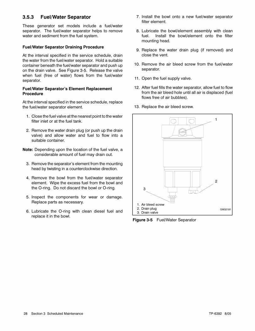
3.5.3 Fuel/Water Separator
These generator set models include a fuel/water
separator. The fuel/water separator helps to remove
water and sediment from the fuel system.
Fuel/Water Separator Draining Procedure
At the interval specified in the service schedule, drain
the water from the fuel/water separator. Hold a suitable
container beneath the fuel/water separator and push up
on the drain valve. See Figure 3-5. Release the valve
when fuel (free of water) flows from the fuel/water
separator.
Fuel/Water Separator’s Element Replacement
Procedure
At the interval specified in the service schedule, replace
the fuel/water separator element.
1. Close the fuel valve at the nearest point to thewater
filter inlet or at the fuel tank.
2. Remove the water drain plug (or push up the drain
valve) and allow water and fuel to flow into a
suitable container.
Note: Depending upon the location of the fuel valve, a
considerable amount of fuel may drain out.
3. Remove the separator’s element from the mounting
head by twisting in a counterclockwise direction.
4. Remove the bowl from the fuel/water separator
element. Wipe the excess fuel from the bowl and
the O-ring. Do not discard the bowl or O-ring.
5. Inspect the components for wear or damage.
Replace parts as necessary.
6. Lubricate the O-ring with clean diesel fuel and
replace it in the bowl.
7. Install the bowl onto a new fuel/water separator
filter element.
8. Lubricate the bowl/element assembly with clean
fuel. Install the bowl/element onto the filter
mounting head.
9. Replace the water drain plug (if removed) and
close the vent.
10. Remove the air bleed screw from the fuel/water
separator.
11. Open the fuel supply valve.
12. After fuel fills the water separator, allow fuel to flow
from the air bleed hole until all air is displaced (fuel
flows free of air bubbles).
13. Replace the air bleed screw.
1
GM32181
1. Air bleed screw2. Drain plug3. Drain valve
2
3
Figure 3-5 Fuel/Water Separator
TP-6392 8/05 29Section 3 Scheduled Maintenance
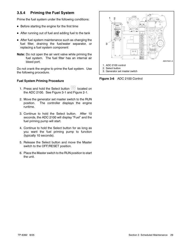
3.5.4 Priming the Fuel System
Prime the fuel system under the following conditions:
Before starting the engine for the first time
After running out of fuel and adding fuel to the tank
After fuel system maintenance such as changing the
fuel filter, draining the fuel/water separator, or
replacing a fuel system component
Note: Do not open the air vent valve while priming the
fuel system. The fuel filter has an internal air
bleed port.
Do not crank the engine to prime the fuel system. Use
the following procedure.
Fuel System Priming Procedure
1. Press and hold the Select button located on
the ADC 2100. See Figure 3-1 and Figure 2-1.
2. Move the generator set master switch to the RUN
position. The controller displays the engine
runtime.
3. Continue to hold the Select button. After 10
seconds, the ADC 2100 will display “Fuel” and the
fuel priming pump will start.
4. Continue to hold the Select button for as long as
you want the fuel priming pump to function
(typically 10 seconds).
5. Release the Select button and move the Master
switch to the OFF/RESET position.
6. Place theMaster switch to theRUNposition to start
the unit.
1. ADC 2100 control2. Select button3. Generator set master switch
3
1 2
ADV7031-A
Figure 3-6 ADC 2100 Control

TP-6392 8/0530 Section 3 Scheduled Maintenance
3.6 Air Cleaner
At the interval specified in the service schedule, inspect,
clean, or replace the air cleaner element. Clean the
element more frequently if the generator operates in
dirty, dusty conditions. Check the element for
accumulated oil or dirt that could cause poor
performance. Replace a damaged air cleaner element.
Follow the procedure described below. At the time of
service, clean the air cleaner breather pipe and remove
all dust and foreign matter from the air cleaner housing.
Air Cleaner Element Cleaning or Replacement
Procedure
1. Lift the locking lever and rotate theair cleaner cover
counterclockwise to remove it. See Figure 3-7.
2. Slide the air cleaner element from the tube.
3. Tap the element lightly against a flat surface to
dislodge loose surface dirt. Do not clean the
element in any liquid or use compressed air as
these will damage the filter element.
4. Wipe the cover and basewith a clean rag to remove
any dirt.
5. Ensure tight clamps at the inlet/outlet connections.
6. Slide the air cleaner element into the tube.
7. Position the cover with the dust ejector pointing
down. Rotate the cover clockwise until the locking
lever snaps into place.
GM39826
1
2
4
3
1. Locking lever2. Cover3. Dust ejector4. Element
Figure 3-7 Air Cleaner Components
3.7 Exhaust System
Carbon monoxide.
Can cause severe nausea,
fainting, or death.
The exhaust system must be
leakproof and routinely inspected.
WARNING
Generator set operation. Carbon monoxide can causesevere nausea, fainting, or death. Carbon monoxide is anodorless, colorless, tasteless, nonirritating gas that can cause
death if inhaled for evena short time. Avoid breathingexhaustfumes when working on or near the generator set. Neveroperate the generator set inside a building unless the exhaustgas is piped safely outside. Never operate the generator setwhere exhaust gas could accumulate and seep back inside apotentially occupied building.
At the interval specified in the service schedule, inspect
the exhaust system.
Inspection Points
Check for exhaust leaks and blockages. Check the
muffler and piping condition and check for tight exhaust
system connections.
Inspect the exhaust system components for cracks and
corrosion (exhaust manifold, exhaust line, exhaust
clamps, and muffler).
Check for corroded or brokenmetal parts and replace
them as needed.
Check for loose, corroded, or missing clamps and
hangers. Tighten or replace the exhaust clamps
and/or hangers as needed.
Check that the exhaust outlet is unobstructed.
Check the exhaust gas color. If the exhaust is blue or
black, contact your local distributor/dealer.
Visually inspect for exhaust leaks (blowby). Check
for carbon or soot residue on exhaust components.
Carbon and soot residue indicates an exhaust leak.
Seal leaks as needed.

TP-6392 8/05 31Section 3 Scheduled Maintenance
3.8 Cooling System
Hot coolant and steam.
Can cause severe injury or death.
Before removing the pressure cap,
stop the generator set and allow it to
cool. Then loosen the pressure cap
to relieve pressure.
WARNING
Checking the coolant level. Hot coolant can causesevereinjury or death. Allow the engine to cool. Release pressurefrom the cooling systembefore removing thepressure cap. To
releasepressure, cover thepressure capwith a thick clothandthen slowly turn the cap counterclockwise to the first stop.Remove the cap after pressure has been completely releasedand theenginehas cooled. Check the coolant level at the tankif the generator set has a coolant recovery tank.
3.8.1 Checking the Cooling System
To prevent generator shutdown or damage because of
overheating, keep the cooling air inlets clean and
unobstructed at all times. Inspect the radiator’s exterior
for obstructions and remove dirt and foreign material
with a soft brush or cloth to avoid damaging the radiator
fins. Check the hoses and connections for leaks and
replace any cracked, frayed, or spongy hoses.
When checking the coolant level, also check the rubber
seal of the radiator’s pressure cap. Replace a cracked
or deteriorated cap. See Section 3.8.5. Remove dirt
and other debris from the pressure cap and filler neck.
See Figure 3-8 for the thermostat rating.
Thermostat Rating
All Models 82C (179F)
Figure 3-8 Thermostat Rating
3.8.2 Draining the Cooling System
The radiator contains a coolant drain valve to drain the
cooling system. When draining the coolant, remove the
radiator’s pressure cap: this will allow the entire system
to drain and will prevent air pockets from forming and
restricting coolant passage to the block.
Note: Pay special attention to the coolant level. After
the coolant drains, allow time for complete refill of
the engine water jacket. Check the coolant level
as described earlier.
3.8.3 Filling the Cooling System
1. Remove the radiator’s pressure cap.
2. Close the radiator’s and/or engine block’s coolant
drain valve(s) and tighten the hose clamps.
Note: Do not add coolant to a hot engine. Adding
coolant to a hot engine can cause the cylinder
block or cylinder head to crack. Wait until engine
has cooled.
3. Fill the radiator with the recommended coolant
mixture of 50% ethylene glycol and 50% clean,
softened water to inhibit rust/corrosion and prevent
freezing. See Figure 3-9 for coolant capacities.
Note: A coolant solution of 50% ethylene glycol
provides freezing protection to --37°C (--34°F)
and overheating protection to 129°C (265°F). A
coolant solution with less than 50% ethylene
glycol may not provide adequate freezing and
overheating protection. A coolant solution with
more than 50% ethylene glycol can cause engine
or component damage. Do not use alcohol or
methanol antifreeze or mix them with the
specified coolant. Consult the engine
manufacturer’s operation manual for engine
coolant specifications.
4. Replace the radiator’s pressure cap.
5. Operate the engine until the thermostat opens and
the radiator upper hose becomes warm.
Model
Engine,L (Qts.)
Engine & Unit-Mounted Radiator,
L (Qts.)
10REOD/REOZD 1.8 (1.9) 4.1 (4.3)
15REOD/REOZD 2.0 (2.1) 9.1 (9.6)
20REOD/REOZD 2.7 (2.8) 9.3 (9.8)
Figure 3-9 Coolant Capacities

TP-6392 8/0532 Section 3 Scheduled Maintenance
6. Stop the engine and allow it to cool.
7. Remove the radiator’s pressure cap.
8. Add coolant to the radiator to just below the
overflow tube on the filler neck.
9. Replace the radiator’s pressure cap.
10. Maintain the coolant level in the coolant overflow
bottle between the High and Low markings.
Note: Periodically check the coolant level by
removing the radiator’s pressure cap. Do
not rely solely on the level in the coolant
overflow bottle. Add fresh coolant until the
level is just below the overflow tube opening.
3.8.4 Flushing and Cleaning
For optimum protection, drain, flush, and refill the
cooling system at the interval listed in the service
schedule.
Flushing and Cleaning Procedure
1. Remove the pressure cap and open the radiator’s
coolant drain valve and let the system drain
completely. Remove the pressure cap to simplify
draining.
2. Drain, clean, and flush the coolant overflow bottle.
3. Flush the system with clean water.
4. Close the radiator’s coolant drain valve.
5. Fill the system with the recommended coolant.
6. Replace the pressure cap.
3.8.5 Pressure Cap
The cooling system utilizes a pressure cap to raise the
boiling point of the coolant, enabling higher operating
temperatures. If the cap leaks, replace it with a cap of the
same rating. See Figure 3-10.
Pressure Cap Rating
10REOD/REOZD 97 kPa (14 psi)
15REOD/REOZD20REOD/REOZD
83--110 kPa (12--16 psi)
Figure 3-10 Pressure Cap Rating
(for inline radiator models)
3.9 Belt Check
Check the belt tension at the intervals specified in the
service schedule. If the tension is not within
specification, adjust as necessary using the following
procedure.
Note: Also check the fan belt for cracks or tears and
replace the belt if necessary.
Adjust the tension of the alternator/fan belt so that the
belt can be depressed about 12.7 mm (0.5 in.) when
applying finger pressure. Use the following procedure
to adjust the belt.
1. Battery charging alternator pulley2. Adjusting screw3. Check the alternator belt tension here4. Alternator pivot screw
2
1
4
3
Figure 3-11 Belt Tension
Belt Tensioning Procedure
1. Disconnect the battery, negative lead first.
2. Loosen the pivot and adjusting screws.
3. While prying the battery charging alternator
outward, tighten the adjusting screw.
4. Tighten the pivot screw.
5. Recheck and adjust as necessary.
6. Reconnect the battery, negative lead last.

TP-6392 8/05 33Section 3 Scheduled Maintenance
3.10 Battery
Consult the battery manufacturer’s instructions
regarding battery care and maintenance.
Sulfuric acid in batteries.Can cause severe injury or death.
Wear protective goggles andclothing. Battery acid may cause
blindness and burn skin.
WARNING
Battery electrolyte is a diluted sulfuric acid. Battery acidcan cause severe injury or death. Battery acid can causeblindness and burn skin. Always wear splashproof safetygoggles, rubber gloves, and boots when servicing the battery.Do not open a sealed battery or mutilate the battery case. If
battery acid splashes in the eyes or on the skin, immediatelyflush the affected area for 15 minutes with large quantities ofclean water. Seek immediate medical aid in the case of eyecontact. Never addacid to a battery after placing the battery inservice, as this may result in hazardous spattering of batteryacid.
Explosion.Can cause severe injury or death.Relays in the battery chargercause arcs or sparks.
Locate the battery in awell-ventilatedarea. Isolate thebattery charger fromexplosive fumes.
WARNING
Battery gases. Explosion can cause severe injury ordeath. Battery gases can cause an explosion. Do not smokeor permit flames or sparks to occur near a battery at any time,
particularlywhen it is charging. Donot disposeof abattery inafire. To prevent burns and sparks that could cause anexplosion, avoid touching the battery terminals with tools orother metal objects. Remove all jewelry before servicing theequipment. Discharge static electricity from your body beforetouching batteries by first touching a grounded metal surface
away from the battery. To avoid sparks, do not disturb thebattery charger connections while the battery is charging.Always turn the battery charger off before disconnecting thebattery connections. Ventilate the compartments containingbatteries to prevent accumulation of explosive gases.

TP-6392 8/0534 Section 3 Scheduled Maintenance
3.11 Storage Procedure
Perform the following storage procedure before taking a
generator set out of service for three months or longer.
Follow the engine manufacturer’s recommendations, if
available, for fuel system and internal engine
component storage.
x:sm:002:001
3.11.1 Lubricating System
Prepare the engine lubricating system for storage as
follows:
1. Run the generator set for a minimum of 15 minutes
to bring it to normal operating temperature.
2. Stop the generator set.
3. With the engine still warm, drain the oil from the
crankcase.
4. Remove and replace the oil filter.
5. Refill the crankcase with oil suited to the climate.
6. Run the generator set for two minutes to distribute
the clean oil.
7. Stop the generator set.
8. Check the oil level and adjust, if needed.
x:sm:002:002
3.11.2 Cooling System
Prepare the cooling system for storage as follows:
1. Check the coolant freeze protection using a
coolant tester.
2. Add or replace coolant as necessary to ensure
adequate freezing protection. Use the guidelines
included in the engine operation manual.
3. Run the generator set for 10--15 minutes to
redistribute added coolant.
x:sm:002:003
3.11.3 Fuel System
Prepare the fuel system for storage as follows:
Diesel-Fueled Engines
1. Fill the fuel tank with #2 diesel fuel.
2. Condition the fuel system with compatible
additives to control microbial growth.
3. Change the fuel filter/separator and prime the fuel
system.
x:sm:002:004
3.11.4 Exterior
Prepare the exterior for storage as follows:
1. Clean the exterior surface of the generator set.
2. Seal all engine openings except for the air intake
with nonabsorbent adhesive tape.
3. To prevent impurities from entering the air intake
and to allow moisture to escape from the engine,
secure a cloth over the air intake.
4. Mask electrical connections.
5. Spread a light film of oil over unpainted metallic
surfaces to inhibit rust and corrosion.
x:sm:002:006a
3.11.5 Battery
Perform battery storage after all other storage
procedures.
1. Place the generator set master switch in the OFF
position.
2. Disconnect the battery(ies), negative (--) lead first.
3. Clean the battery. Refer to the battery
manufacturer for the battery cleaning procedure.
4. Place the battery in a cool, dry location.
5. Connect the battery to a float/equalize battery
charger or charge it monthly with a trickle battery
charger. Refer to the battery charger
manufacturer’s recommendations.
Maintain a full charge to extend battery life.
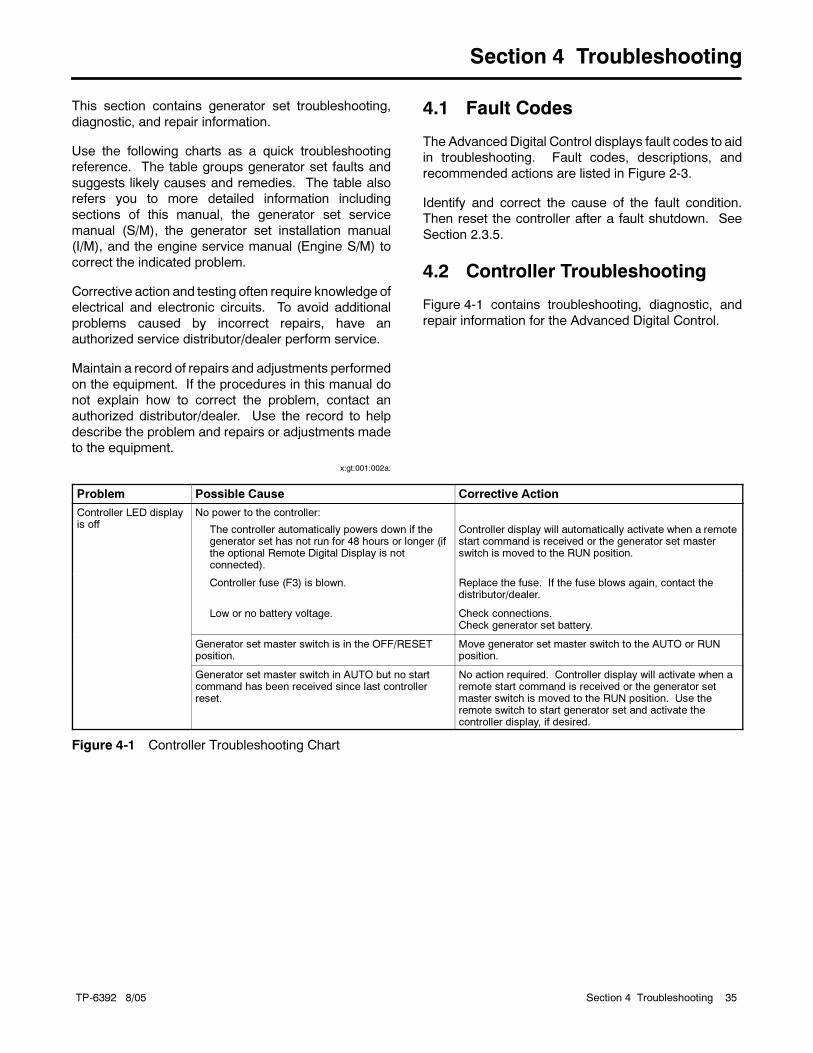
TP-6392 8/05 35Section 4 Troubleshooting
Section 4 Troubleshooting
This section contains generator set troubleshooting,
diagnostic, and repair information.
Use the following charts as a quick troubleshooting
reference. The table groups generator set faults and
suggests likely causes and remedies. The table also
refers you to more detailed information including
sections of this manual, the generator set service
manual (S/M), the generator set installation manual
(I/M), and the engine service manual (Engine S/M) to
correct the indicated problem.
Corrective action and testing often require knowledge of
electrical and electronic circuits. To avoid additional
problems caused by incorrect repairs, have an
authorized service distributor/dealer perform service.
Maintain a record of repairs and adjustments performed
on the equipment. If the procedures in this manual do
not explain how to correct the problem, contact an
authorized distributor/dealer. Use the record to help
describe the problem and repairs or adjustments made
to the equipment.
x:gt:001:002a:
4.1 Fault Codes
The Advanced Digital Control displays fault codes to aid
in troubleshooting. Fault codes, descriptions, and
recommended actions are listed in Figure 2-3.
Identify and correct the cause of the fault condition.
Then reset the controller after a fault shutdown. See
Section 2.3.5.
4.2 Controller Troubleshooting
Figure 4-1 contains troubleshooting, diagnostic, and
repair information for the Advanced Digital Control.
Problem Possible Cause Corrective Action
Controller LED displayis off
No power to the controller:
The controller automatically powers down if thegenerator set has not run for 48 hours or longer (ifthe optional Remote Digital Display is notconnected).
Controller display will automatically activate when a remotestart command is received or the generator set masterswitch is moved to the RUN position.
Controller fuse (F3) is blown. Replace the fuse. If the fuse blows again, contact thedistributor/dealer.
Low or no battery voltage. Check connections.Check generator set battery.
Generator set master switch is in the OFF/RESETposition.
Move generator set master switch to the AUTO or RUNposition.
Generator set master switch in AUTO but no startcommand has been received since last controllerreset.
No action required. Controller display will activate when aremote start command is received or the generator setmaster switch is moved to the RUN position. Use theremote switch to start generator set and activate thecontroller display, if desired.
Figure 4-1 Controller Troubleshooting Chart

TP-6392 8/0536 Section 4 Troubleshooting
Trouble
Symptoms
Doesnotcrank
Cranksbutdoesnotstart
Startshard
Noorlowoutputvoltage
Stopssuddenly
Lackspower
Overheats
Lowoilpressure
Highfuelconsumption
Excessiveorabnormalnoise
Probable
Causes
RecommendedActions
Sectionor
Publication
Reference*
Controller
xx
Generatorsetmasterswitchin
the
OFFposition
Movethegeneratorsetmasterswitchto
thecorrectposition
(RUNorAUTO).
Section2
xx
Controlle
rfuse(F3)blown
Replacetheblowncontrolle
rfuse.Ifthefuseblowsagain,
troubleshootthecontroller.
Section2,W/D
xx
Relayinterfaceboard
fuse(F2)blown
Replacetheblownrelayinterfaceboard
fuse.Ifthefuseblows
again,troubleshootthecontroller.
Section2,W/D
xAuxiliary
windingfuse(F1)blown
Replacetheblownauxiliary
windingfuse.Ifthefuseblows
again,troubleshootthecontroller.
Section2,W/D
xx
Controllercircuitbreakertripped
Resetthecontrollercircuitbreaker.
Section2
xControllermasterorstart/stopswitch
inoperative
Replacethecontrolle
rmasterswitch.
—
xControllerfault
Troubleshootthecontroller.
Gen.S/M
xRemote
stopcommandreceivedfrom
aremote
switchorATS
Checktheremote
switchposition.
CoolingSystem
xx
Airopeningsclogged
Cleantheairopenings.
—
xHightemperature
shutdown
Allo
wtheengineto
cooldown.Thentroubleshootthecoolin
gsystem.
Section.3.8,and
Eng.O/M
xLowcoolantlevelshutdown
Restore
thecoolantto
norm
aloperatinglevelandresetthe
controller.
Sections3.8
and
2.3.5
xCoolantlevellow
Restore
thecoolantto
norm
aloperatinglevel.
Section3.8
xTherm
ostatinoperative
Replacethetherm
ostat.
Eng.S/M
xCoolin
gwaterpumpinoperative
Tightenorreplacethebelt.Replacethewaterpump.
Eng.O/M
orS/M
*Sec./Section—numberedsectionofthismanual;ATS—AutomaticTransferSwitch;Eng.—
Engine;Gen.—
GeneratorSet;I/M—InstallationManual;O/M
—OperationManual;S/M
—ServiceManual;
S/S—SpecSheet;W/D—WiringDiagram
Haveanauthorizedservicedistributor/dealerperform
this
service.
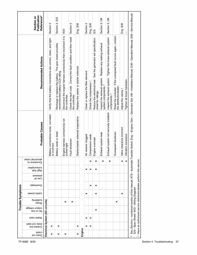
TP-6392 8/05 37Section 4 Troubleshooting
Sectionor
Publication
Reference*
RecommendedActions
Probable
Causes
Trouble
Symptoms
Sectionor
Publication
Reference*
RecommendedActions
Probable
Causes
Excessiveorabnormalnoise
Highfuelconsumption
Lowoilpressure
Overheats
Lackspower
Stopssuddenly
Noorlowoutputvoltage
Startshard
Cranksbutdoesnotstart
Doesnotcrank
ElectricalSystem
(DCcircuits)
xx
Battery
connectionsloose,corroded,
orincorrect
Verify
thatthebattery
connectionsare
correct,clean,andtight.
Section3
xx
Battery
weakordead
Rechargeorreplacethebattery.Thespecsheetprovides
recommendedbattery
CCArating.
Section3,S/S
xx
Engineharnessconnector(s)not
lockedtight
Disconnecttheengineharnessconnector(s)thenreconnectitto
thecontroller.
W/D
xFaultshutdown
Checkthefaultcode.Correctthefaultconditionandthenreset
thecontroller.
Section2
xx
Starter/startersolenoid
inoperative
Replacethestarterorstartersolenoid.
Eng.S/M
Engine
xx
xx
Aircleanerclogged
Cleanorreplacethefilterelement.
Section2
xx
xx
xCompressionweak
Checkthecompression.
Eng.S/M
xx
xx
xEngineoverload
Reducetheelectricalload.Seethegeneratorsetspecification
sheetforratings.
S/S
xExhaustsystem
leak
Inspecttheexhaustsystem.Replaceanyleakingexhaust
system
components.
Section3,I/M
xExhaustsystem
notsecurely
installe
dInspecttheexhaustsystem.Tightenthelooseexhaustsystem
components.
Section3,I/M
xOverspeedshutdown
Resetthecontrolle
r.Iftheoverspeedfaultoccurs
again,contact
thedistributor/dealer.
xx
Valveclearanceincorrect
Adjustthevalves.
Eng.S/M
xVibrationexcessive
Tightenallloosehardware.
—
*Sec./Section—numberedsectionofthismanual;ATS—AutomaticTransferSwitch;Eng.—
Engine;Gen.—
GeneratorSet;I/M—InstallationManual;O/M
—OperationManual;S/M
—ServiceManual;
S/S—SpecSheet;W/D—WiringDiagram
Haveanauthorizedservicedistributor/dealerperform
this
service.

TP-6392 8/0538 Section 4 Troubleshooting
Sectionor
Publication
Reference*
RecommendedActions
Probable
Causes
Trouble
Symptoms
Sectionor
Publication
Reference*
RecommendedActions
Probable
Causes
Excessiveorabnormalnoise
Highfuelconsumption
Lowoilpressure
Overheats
Lackspower
Stopssuddenly
Noorlowoutputvoltage
Startshard
Cranksbutdoesnotstart
Doesnotcrank
FuelSystem
xx
Fueltankempty
orfuelvalveshutoff
Addfuelandmovethefuelvalveto
theONposition.
—
xx
xx
Fuelfilterrestriction
Cleanorreplacethefuelfilter.
Section3.5
xFuelsolenoid
inoperative
Troubleshootthefuelsolenoid.
Eng.S/M
xx
xAirin
fuelsystem
(dieselonly)
Primethedieselfuelsystem.
Section3.5.4
xx
xFuelorfuelinjectors
dirty
orfaulty
(dieselonly)
Clean,test,and/orreplacetheinoperativefuelinjector.
Eng.S/M
xx
xx
Fuelinjectiontimingoutofadjustm
ent
(dieselonly)
Adjustthefuelinjectiontiming.
Eng.S/M
xx
xFuelfeedorinjectionpumpinoperative
(dieselonly)
Rebuild
orreplacetheinjectionpump.
Eng.S/M
Generator
xACoutputcircuitbreakeropen
ResetthebreakerandcheckforACvoltageatthegenerator
sideofthecircuitbreaker.
—
xOvercrankshutdown
Resetthecontrolle
r.Iftheovercrankfaultoccurs
again,contact
thedistributor/dealer.
—
xTransferswitchtestswitchin
theOFF
position
Movethetransferswitchtestswitchto
theAUTO
position.
ATSO/M
xWiring,term
inals,orpin
intheexciter
field
open
Checkforcontinuity.
Gen.S/M
,W/D
xMain
field
(rotor)inoperative(openor
grounded)
Testand/orreplacetherotor.
Gen.S/M
xStatorinoperative(openorgrounded)
Testand/orreplacethestator.
Gen.S/M
xVibrationexcessive
Tightenloosecomponents.
—
LubeSystem
xx
xOillevellow
Restore
theoillevel.
Inspectthegeneratorsetforoilleaks.
Section3.4
xLowoilpressure
shutdown
Checktheoillevel.
Section3.4
xx
xx
Crankcaseoiltypeincorrectfor
ambienttemperature
Changetheoil.
Useoilwithaviscositysuitable
fortheoperating
clim
ate.
Section3.4
*Sec./Section—numberedsectionofthismanual;ATS—AutomaticTransferSwitch;Eng.—
Engine;Gen.—
GeneratorSet;I/M—InstallationManual;O/M
—OperationManual;S/M
—ServiceManual;
S/S—SpecSheet;W/D—WiringDiagram
Haveanauthorizedservicedistributor/dealerperform
this
service.

TP-6392 8/05 39Section 5 Reconnection/Adjustments
Section 5 Reconnection/Adjustments
5.1 Four-Lead Reconnection
The following information illustrates the reconnection of
four-lead generator sets. In all cases, conform to the
National Electrical Code (NEC).
NOTICE
Voltage reconnection. Affix anotice to thegenerator setafterreconnecting the set to a voltage different from the voltage on
the nameplate. Order voltage reconnection decal 246242from an authorized service distributor/dealer.
5.1.1 100--120-Volt Configurations
If the installation requires a factory two-pole circuit
breaker, do not connect the load-side terminals of the
circuit breaker together; see Figure 5-1. If the
installation requires a 100--120-volt, 2-wire system, use
a single-pole circuit breaker. See Figure 5-2. When
connecting stator phase leads together, size the output
lead (L1) to handle the amperage. Use a jumper lead on
the line side of the circuit breaker to balance the load of
the generator set.
GRD.
L1
L2
4 3 2 1
L0 (Neutral)L0
Ground
LoadSide
LineSide
Two-PoleCircuitBreaker
Jumperlead
60 Hz 50 Hz
L0--L1 100--120 Volt 100--120 VoltL0--L2 100--120 Volt 100--120 Volt
Figure 5-1 100--120-Volt, 3-Wire Configuration
5.1.2 100--120/200--240-Volt
Configurations
The 100--120/200--240-volt configuration does not use
a jumper lead. If the unit was originally wired for straight
100--120 volt, 3-wire, remove the jumper lead (see
Figure 5-1 for location). Select a two-pole circuit
breaker. Application of two single-pole circuit breakers
does not conform to NEC requirements for supplying a
200--240-volt load, even if the breakers are
mechanically attached together. Leads L1 and L2 are
for different phases; never connect them together.
4 3 2 1
Stator Leads
L0
GRD.
L1
L0 (Neutral)
LineSide
Single-PoleCircuitBreaker
Ground
LoadSide
60 Hz 50 Hz
L0--L1 100--120 Volt 100--120 Volt
Figure 5-2 100--120 Volt, 2-Wire Configuration

TP-6392 8/0540 Section 5 Reconnection/Adjustments
4 3 2 1
Stator Leads
L0
GRD.
L2L1
L0 (Neutral)
LineSide
FactoryTwo-PoleCircuitBreaker
Ground
LoadSide
100--120/200--240-Volt,3-Wire
60 Hz 50 Hz
L0--L1 100--120 Volt 100--120 VoltL0--L2 100--120 Volt 100--120 VoltL1--L2 200--240 Volt 200--240 Volt
Figure 5-3 100--120/200--240-Volt, 3-Wire
Configuration
5.1.3 200--240-Volt Configurations
The 200--240-volt configuration does not use a jumper
lead. If the unit was originally wired for straight 100--120
volt, 3-wire, remove the jumper lead (see Figure 5-1 for
location). See Figure 5-4.
4 3 21
Stator Leads
L0
GRD.
L1
L0 (Neutral)
LineSide
Single-PoleCircuitBreaker
Ground
LoadSide
200--220--240 Volt2 Wire
Tape to insulatefrom ground
60 Hz
L0--L1 200-240 Volt 200--220--240 Volt
50 Hz
Figure 5-4 200--220--240-Volt, 2-Wire Configuration
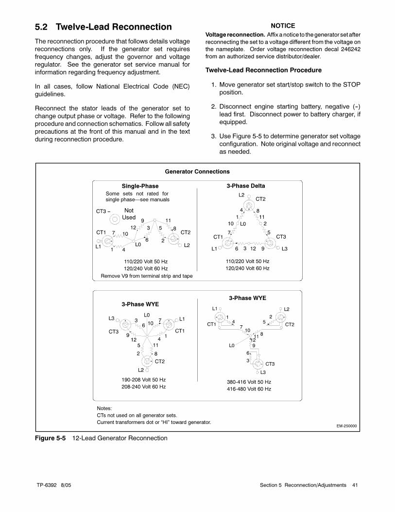
TP-6392 8/05 41Section 5 Reconnection/Adjustments
5.2 Twelve-Lead Reconnection
The reconnection procedure that follows details voltage
reconnections only. If the generator set requires
frequency changes, adjust the governor and voltage
regulator. See the generator set service manual for
information regarding frequency adjustment.
In all cases, follow National Electrical Code (NEC)
guidelines.
Reconnect the stator leads of the generator set to
change output phase or voltage. Refer to the following
procedure and connection schematics. Follow all safety
precautions at the front of this manual and in the text
during reconnection procedure.
NOTICE
Voltage reconnection. Affix anotice to thegenerator setafter
reconnecting the set to a voltage different from the voltage on
the nameplate. Order voltage reconnection decal 246242
from an authorized service distributor/dealer.
Twelve-Lead Reconnection Procedure
1. Move generator set start/stop switch to the STOP
position.
2. Disconnect engine starting battery, negative (--)
lead first. Disconnect power to battery charger, if
equipped.
3. Use Figure 5-5 to determine generator set voltage
configuration. Note original voltage and reconnect
as needed.
EM-250000
Generator Connections
Single-Phase
Not
Used
Some sets not rated forsingle phase—see manuals
110/220 Volt 50 Hz
120/240 Volt 60 Hz
Remove V9 from terminal strip and tape
3-Phase Delta
110/220 Volt 50 Hz
120/240 Volt 60 Hz
3-Phase WYE
190-208 Volt 50 Hz
208-240 Volt 60 Hz
3-Phase WYE
380-416 Volt 50 Hz
416-480 Volt 60 Hz
Notes:
CTs not used on all generator sets.
Current transformers dot or “HI” toward generator.
Figure 5-5 12-Lead Generator Reconnection

TP-6392 8/0542 Section 5 Reconnection/Adjustments
5.3 ADC 2100 Adjustment after
Reconnection
Figure 5-6 Advanced Digital Control (ADC 2100)
The controller is factory-set for the generator set voltage
and frequency and normally does not require
adjustment. If adjustment is necessary, follow the
procedures in this section to set the system voltage and
frequency parameter (Uu) and then adjust the output
voltage.
Note: The unit configuration (UC), engine type (EC),
and engine data input type (ED) are factory set
and should only be changed by an authorized
Kohler dealer/distributor. Incorrect settings will
make your unit non-functional.
5.3.1 Configuration Mode Time Out
The controller will automatically exit the configuration
modewithout saving any changes after about 1minute if
no buttons are pressed. Start the configuration
procedure over again from the beginning if the controller
exits the configuration mode before the settings have
been saved.
5.3.2 Configuration Mode
Follow the instructions in Figure 5-10 to enter the
configuration mode. The settings are shown in
Figure 5-7. An X in the Display column in Figure 5-10
indicates a number from 0 to 9.
Press the Select button to step through to the Save
mode as shown in Figure 5-12. When SAVE is
displayed, press the uparrow to save thenewsettingsor
the down arrow to discard the changes and exit the
configuration mode without saving.
Pressing the Select button when SAVE is displayed
returns to the first parameter, system voltage/frequency
(Uu).
Parameter Setting Definition
Unit’s system voltaged f
Uu01 Single phase, 60 Hz, 120/240 VACy gand frequencyAlso see Figure 5 8
Uu03 Three phase, 50 Hz, 115/230 or 200/400 VACAlso see Figure 5-8
Uu04 Three phase, 60 Hz, 138/277 or 240/480 VAC
Uu06 Single phase, 50 Hz, 115/230 VAC
Unit configuration Uc01 * Standby generator set
Engine type Ec02 * 10/15/20REOD/REOZD
Engine data input types Ed01 * Units with standard oil pressure switchg p yp
Ed02 Units with optional oil pressure sender installed (i.e. for Remote Digital Gauge)
Battery Voltage Bt12 * Battery voltage 12 VDC
Communications Cn00 * No CAN communications
Cn01 J1939 (use for Remote Digital Gauge)
* Factory settings.
Figure 5-7 Controller Parameters

TP-6392 8/05 43Section 5 Reconnection/Adjustments
Voltage Connection VACVoltagePart #
ADC2100
Setting
60 Hz, Single phase 120/240 333702 Uu01
60 Hz, Three phase 120/208 333700, p
127/220 333701
120/240 333703Uu04
139/240 333704Uu04
220/380 333705
277/480 333708
50 Hz, Single phase 110/220 333803 Uu06
50 Hz, Three phase 110/190 333800, p
110/220 333802
220/380 333805 Uu03
230/400 333806
240/416 333807
Figure 5-8 Uu Parameter Settings for Available
Voltage Connections
5.3.3 Voltage Adjustment
After setting the system voltage parameter Uu, check
the output voltage and adjust, if necessary, using the
following procedures. Follow the instructions in
Figure 5-13 to adjust the voltage, gain, and volts/Hz
while the engine is running. An X in the Display column
in Figure 5-13 indicates a number from 0 to 9. Use the
up arrow to increase a setting or the down arrow to
decrease the setting.
Pressing the Select button when SAVE is displayed
returns to the first parameter, voltage adjust (1P).
Note: A digital multimeter that measures voltage and
frequency is required for these adjustments.
Hazardous voltage.Can cause severe injury or death.
Operate the generator set only whenall guards and electrical enclosures
are in place.
Moving rotor.
WARNING
Short circuits. Hazardous voltage/current can causesevere injury or death. Short circuits can cause bodily injuryand/or equipment damage. Do not contact electrical
connections with tools or jewelry whilemaking adjustments orrepairs. Remove all jewelry before servicing the equipment.
Grounding electrical equipment. Hazardous voltage cancause severe injury or death. Electrocution is possiblewhenever electricity is present. Open the main circuitbreakers of all power sources before servicing the equipment.
Configure the installation to electrically ground the generatorset, transfer switch, and related equipment and electricalcircuits to complywith applicable codesandstandards. Nevercontact electrical leads or appliances when standing in wateror onwetgroundbecause theseconditions increase the riskofelectrocution.
Voltage Adjustment Procedure
1. With the generator set off, connect a digital
voltmeter to the output leads or an electrical outlet
on the load side of the generator set. Set themeter
to measure voltage.
2. Start the generator set bymoving the generator set
master switch to the RUN position.
3. Use the ADC controller to adjust the voltage
(parameter 1P) until the output voltage reaches the
desired value. See Figure 5-9.
MeasuredVoltage, VAC
ApproximateVoltage Change per Step, VACg ,
Coarse Adjust Fine Adjust
85--132 5 0.5
180--251 7 0.7
Figure 5-9 Voltage Adjustment
4. Adjust the voltage stability (gain, parameter 2P) to
minimize light flicker.
5. Readjust the voltage, if necessary.
6. Adjust the volts/Hz (parameter 3P) until the voltage
level measured by the voltmeter begins to drop.
When the volts/Hz is set correctly, the generator
(as load is applied) attempts to maintain normal
output until the engine speed drops below the
cut-in frequency.
7. Readjust the voltage stability (gain, parameter 2P),
if necessary.
8. Readjust the voltage (parameter 1P), if necessary.
9. Stop the generator set.
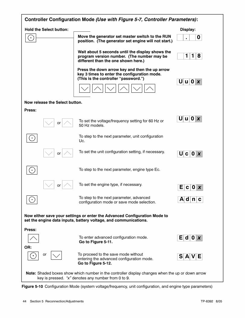
TP-6392 8/0544 Section 5 Reconnection/Adjustments
Wait about 5 seconds until the display shows theprogram version number. (The number may bedifferent than the one shown here.)
Hold the Select button:
orTo set the voltage/frequency setting for 60 Hz or50 Hz models.
To step to the next parameter, unit configurationUc.
or To set the unit configuration setting, if necessary.
To step to the next parameter, engine type Ec.
To step to the next parameter, advancedconfiguration mode or save mode selection.
Move the generator set master switch to the RUNposition. (The generator set engine will not start.)
Display:
or To set the engine type, if necessary.
U u 0 x
U c 0 x
U u 0 x
1 1 8
. 0
A d n c
Press:
Now release the Select button.
OR:
To enter advanced configuration mode.Go to Figure 5-11.
or To proceed to the save mode withoutentering the advanced configuration mode.Go to Figure 5-12.
Now either save your settings or enter the Advanced Configuration Mode toset the engine data inputs, battery voltage, and communications.
Press:
S A V E
E d 0 x
E c 0 x
Note: Shaded boxes show which number in the controller display changes when the up or down arrow
key is pressed. “x” denotes any number from 0 to 9.
Press the down arrow key and then the up arrowkey 3 times to enter the configuration mode.(This is the controller “password.”)
Controller Configuration Mode (Use with Figure 5-7, Controller Parameters):
Figure 5-10 Configuration Mode (system voltage/frequency, unit configuration, and engine type parameters)

TP-6392 8/05 45Section 5 Reconnection/Adjustments
or To set the engine data input type.
To enter battery voltage selection mode.
or To toggle between 12 and 24 VDC.
To enter communications selection mode.
orTo set the communications parameter.
To enter SAVE mode. Go to Figure 5-12.
E d 0 x
Pressing the up arrow key at the Adnc display (See Figure 5-10) puts youinto the Advanced Configuration Mode.
Press:
B t 1 2
C n 0 x
S A V E
12-volt models
Note: Shaded boxes show which number in the controller display changes when the up or down arrow
key is pressed. “x” denotes any number from 0 to 9.
Figure 5-11 Advanced Configuration Mode (engine data input types, battery voltage, and engine
communications)
To save changes.
To discard changes without saving.
or
Note: Be sure to save your settings before exiting the configuration mode. The controller reverts to the
last saved settings when the master switch is moved to the OFF/RESET position.
* x in the runtime hours display above denotes any number from 0 to 9.
S A V E
Y E S
Now move the master switch to OFF/RESET.
n o
There are 3 options when the display says SAVE:Press:
x x xx
or
To return to the first parameter, system voltage/frequencyUu, to check or change settings before saving. SeeFigure 5-10.
U u 0 x
“Yes”or “no” flashes when the up or down arrow is pressed and thenthe controller exits the configuration mode. The display returns tothe runtime hours.
Figure 5-12 Save Mode (after configuring generator set parameters)

TP-6392 8/0546 Section 5 Reconnection/Adjustments
TP6196
Move the generator set master switch to the RUN position. The generator setengine starts and the controller display shows the engine runtime hours.
Display :*
or
or
To raise or lower the voltage in large increments(approximately 5--7 volts per step).
To enter fine voltage adjustment mode.
To raise or lower the voltage in smaller increments(approximately 0.5--0.7 volts per step).
To enter coarse voltage stability (gain) adjustment mode.
or
To raise or lower the voltage stability (gain) in largeincrements.
To enter fine voltage stability (gain) adjustment mode.
or
To raise or lower the voltage stability (gain) in smallerincrements.
To enter volts/Hz adjustment mode.
To raise or lower the volts/Hz: 00=low; 09= high
or
Hold:Wait about 5 seconds until the display changes from runtime hoursto the program version number.
Press the down arrow key and then the up arrow key 3 times to enter theadjustment mode. (This is the controller “password.”)
x x
x x x x
1 P
1 P
2 P
* Shaded boxes show which character in the controller display changes for each adjustment. “x” in theexamples above denotes any number from 0 to 9. The actual values may vary from model-to-model.
x.
2 P
3 P 0
The controller is now in the voltage coarse adjustment mode.
Press:
1 P
See Figure 5-12 to save.
x x
x x
xx
x x
xx
x
Output Voltage Adjustment Mode:
Figure 5-13 Output Voltage Adjustments
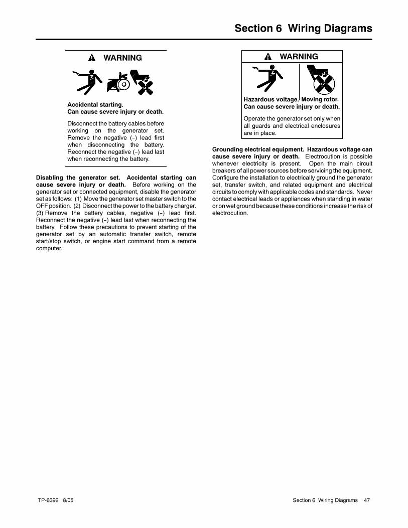
TP-6392 8/05 47Section 6 Wiring Diagrams
Section 6 Wiring Diagrams
Accidental starting.Can cause severe injury or death.
Disconnect the battery cables beforeworking on the generator set.
Remove the negative (--) lead firstwhen disconnecting the battery.Reconnect the negative (--) lead lastwhen reconnecting the battery.
WARNING
Disabling the generator set. Accidental starting cancause severe injury or death. Before working on thegenerator set or connected equipment, disable the generatorset as follows: (1) Move thegenerator setmaster switch to theOFFposition. (2) Disconnect thepower to thebattery charger.
(3) Remove the battery cables, negative (--) lead first.Reconnect the negative (--) lead last when reconnecting thebattery. Follow these precautions to prevent starting of thegenerator set by an automatic transfer switch, remotestart/stop switch, or engine start command from a remote
computer.
Hazardous voltage.
Can cause severe injury or death.
Operate the generator set only when
all guards and electrical enclosures
are in place.
Moving rotor.
WARNING
Grounding electrical equipment. Hazardous voltage cancause severe injury or death. Electrocution is possiblewhenever electricity is present. Open the main circuitbreakers of all power sources before servicing the equipment.Configure the installation to electrically ground the generator
set, transfer switch, and related equipment and electricalcircuits to complywith applicable codesandstandards. Nevercontact electrical leads or appliances when standing in wateror onwetgroundbecause theseconditions increase the riskofelectrocution.

TP-6392 8/0548 Section 6 Wiring Diagrams
GM39874-A
Figure 6-1 Wiring Diagram, GM39874-A

TP-6392 8/05 49Section 6 Wiring Diagrams
ADV7030A-
Figure 6-2 Schematic, ADV-7030, Sheet 1

TP-6392 8/0550 Section 6 Wiring Diagrams
ADV7030B-
Figure 6-3 Schematic, ADV-7030, Sheet 2
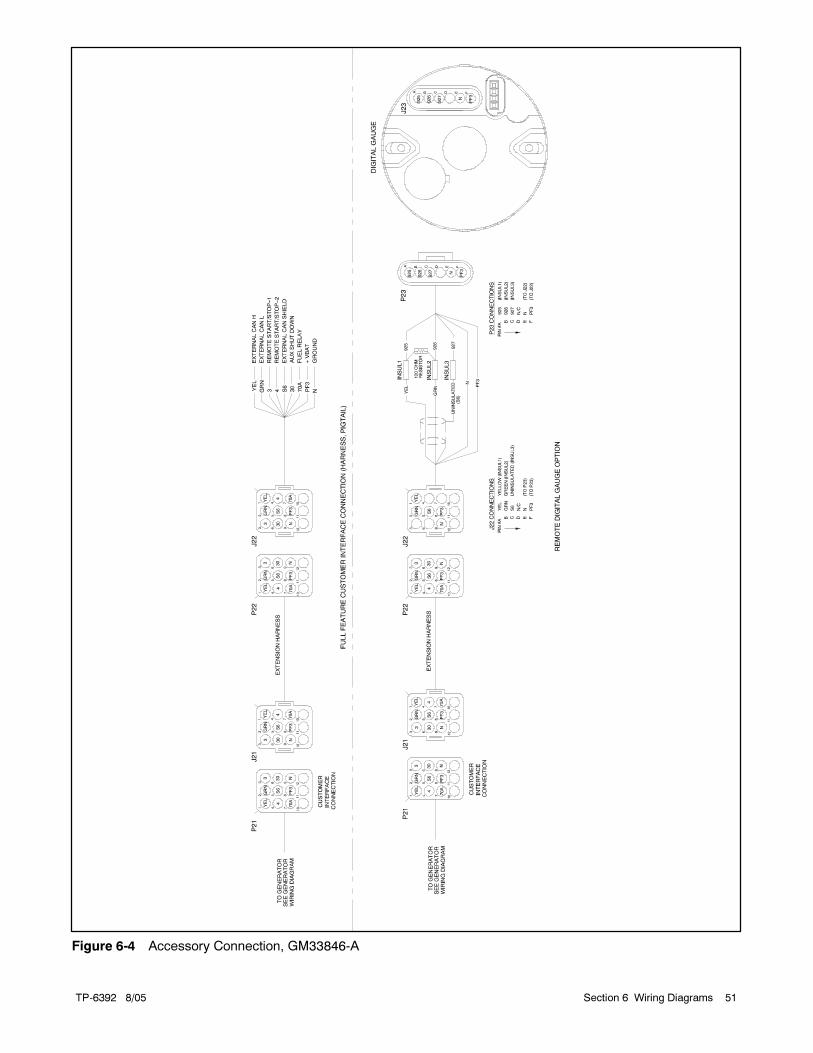
TP-6392 8/05 51Section 6 Wiring Diagrams
Figure 6-4 Accessory Connection, GM33846-A

TP-6392 8/0552 Section 6 Wiring Diagrams
Notes
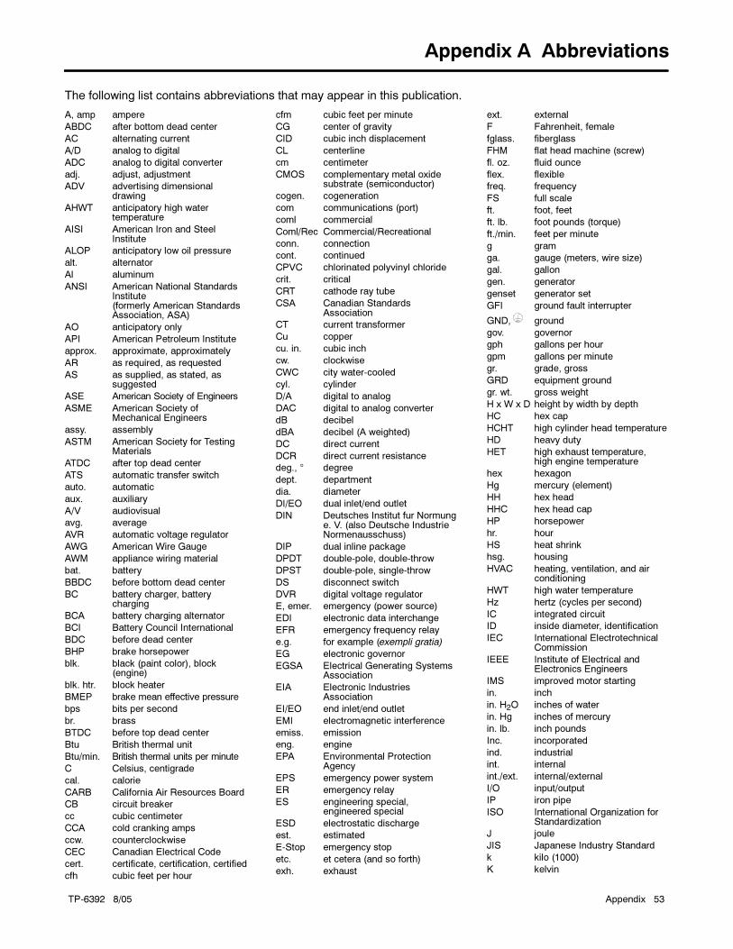
TP-6392 8/05 Appendix 53
Appendix A Abbreviations
The following list contains abbreviations that may appear in this publication.
A, amp ampere
ABDC after bottom dead center
AC alternating current
A/D analog to digital
ADC analog to digital converter
adj. adjust, adjustment
ADV advertising dimensionaldrawing
AHWT anticipatory high watertemperature
AISI American Iron and SteelInstitute
ALOP anticipatory low oil pressure
alt. alternator
Al aluminum
ANSI American National StandardsInstitute(formerly American StandardsAssociation, ASA)
AO anticipatory only
API American Petroleum Institute
approx. approximate, approximately
AR as required, as requested
AS as supplied, as stated, assuggested
ASE American Society of Engineers
ASME American Society ofMechanical Engineers
assy. assembly
ASTM American Society for TestingMaterials
ATDC after top dead center
ATS automatic transfer switch
auto. automatic
aux. auxiliary
A/V audiovisual
avg. average
AVR automatic voltage regulator
AWG American Wire Gauge
AWM appliance wiring material
bat. battery
BBDC before bottom dead center
BC battery charger, batterycharging
BCA battery charging alternator
BCI Battery Council International
BDC before dead center
BHP brake horsepower
blk. black (paint color), block(engine)
blk. htr. block heater
BMEP brake mean effective pressure
bps bits per second
br. brass
BTDC before top dead center
Btu British thermal unit
Btu/min. British thermal units per minute
C Celsius, centigrade
cal. calorie
CARB California Air Resources Board
CB circuit breaker
cc cubic centimeter
CCA cold cranking amps
ccw. counterclockwise
CEC Canadian Electrical Code
cert. certificate, certification, certified
cfh cubic feet per hour
cfm cubic feet per minute
CG center of gravity
CID cubic inch displacement
CL centerline
cm centimeter
CMOS complementary metal oxidesubstrate (semiconductor)
cogen. cogeneration
com communications (port)
coml commercial
Coml/Rec Commercial/Recreational
conn. connection
cont. continued
CPVC chlorinated polyvinyl chloride
crit. critical
CRT cathode ray tube
CSA Canadian StandardsAssociation
CT current transformer
Cu copper
cu. in. cubic inch
cw. clockwise
CWC city water-cooled
cyl. cylinder
D/A digital to analog
DAC digital to analog converter
dB decibel
dBA decibel (A weighted)
DC direct current
DCR direct current resistance
deg., ° degree
dept. department
dia. diameter
DI/EO dual inlet/end outlet
DIN Deutsches Institut fur Normunge. V. (also Deutsche IndustrieNormenausschuss)
DIP dual inline package
DPDT double-pole, double-throw
DPST double-pole, single-throw
DS disconnect switch
DVR digital voltage regulator
E, emer. emergency (power source)
EDI electronic data interchange
EFR emergency frequency relay
e.g. for example (exempli gratia)
EG electronic governor
EGSA Electrical Generating SystemsAssociation
EIA Electronic IndustriesAssociation
EI/EO end inlet/end outlet
EMI electromagnetic interference
emiss. emission
eng. engine
EPA Environmental ProtectionAgency
EPS emergency power system
ER emergency relay
ES engineering special,engineered special
ESD electrostatic discharge
est. estimated
E-Stop emergency stop
etc. et cetera (and so forth)
exh. exhaust
ext. external
F Fahrenheit, female
fglass. fiberglass
FHM flat head machine (screw)
fl. oz. fluid ounce
flex. flexible
freq. frequency
FS full scale
ft. foot, feet
ft. lb. foot pounds (torque)
ft./min. feet per minute
g gram
ga. gauge (meters, wire size)
gal. gallon
gen. generator
genset generator set
GFI ground fault interrupter
GND, ground
gov. governor
gph gallons per hour
gpm gallons per minute
gr. grade, gross
GRD equipment ground
gr. wt. gross weight
H x W x D height by width by depth
HC hex cap
HCHT high cylinder head temperature
HD heavy duty
HET high exhaust temperature,high engine temperature
hex hexagon
Hg mercury (element)
HH hex head
HHC hex head cap
HP horsepower
hr. hour
HS heat shrink
hsg. housing
HVAC heating, ventilation, and airconditioning
HWT high water temperature
Hz hertz (cycles per second)
IC integrated circuit
ID inside diameter, identification
IEC International ElectrotechnicalCommission
IEEE Institute of Electrical andElectronics Engineers
IMS improved motor starting
in. inch
in. H2O inches of water
in. Hg inches of mercury
in. lb. inch pounds
Inc. incorporated
ind. industrial
int. internal
int./ext. internal/external
I/O input/output
IP iron pipe
ISO International Organization forStandardization
J joule
JIS Japanese Industry Standard
k kilo (1000)
K kelvin
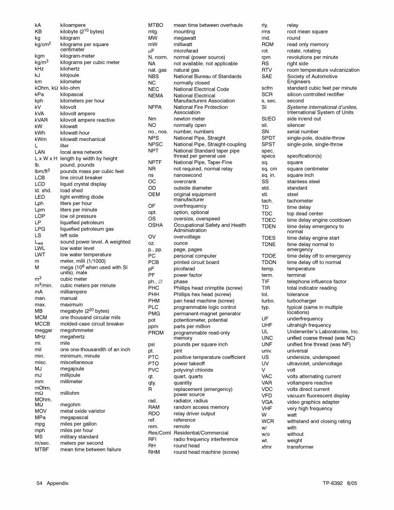
TP-6392 8/0554 Appendix
kA kiloampere
KB kilobyte (210 bytes)
kg kilogram
kg/cm2 kilograms per squarecentimeter
kgm kilogram-meter
kg/m3 kilograms per cubic meter
kHz kilohertz
kJ kilojoule
km kilometer
kOhm, kΩ kilo-ohm
kPa kilopascal
kph kilometers per hour
kV kilovolt
kVA kilovolt ampere
kVAR kilovolt ampere reactive
kW kilowatt
kWh kilowatt-hour
kWm kilowatt mechanical
L liter
LAN local area network
L x W x H length by width by height
lb. pound, pounds
lbm/ft3 pounds mass per cubic feet
LCB line circuit breaker
LCD liquid crystal display
ld. shd. load shed
LED light emitting diode
Lph liters per hour
Lpm liters per minute
LOP low oil pressure
LP liquefied petroleum
LPG liquefied petroleum gas
LS left side
Lwa sound power level, A weighted
LWL low water level
LWT low water temperature
m meter, milli (1/1000)
M mega (106 when used with SIunits), male
m3 cubic meter
m3/min. cubic meters per minute
mA milliampere
man. manual
max. maximum
MB megabyte (220 bytes)
MCM one thousand circular mils
MCCB molded-case circuit breaker
meggar megohmmeter
MHz megahertz
mi. mile
mil one one-thousandth of an inch
min. minimum, minute
misc. miscellaneous
MJ megajoule
mJ millijoule
mm millimeter
mOhm,mΩ milliohm
MOhm,MΩ megohm
MOV metal oxide varistor
MPa megapascal
mpg miles per gallon
mph miles per hour
MS military standard
m/sec. meters per second
MTBF mean time between failure
MTBO mean time between overhauls
mtg. mounting
MW megawatt
mW milliwatt
μF microfarad
N, norm. normal (power source)
NA not available, not applicable
nat. gas natural gas
NBS National Bureau of Standards
NC normally closed
NEC National Electrical Code
NEMA National ElectricalManufacturers Association
NFPA National Fire ProtectionAssociation
Nm newton meter
NO normally open
no., nos. number, numbers
NPS National Pipe, Straight
NPSC National Pipe, Straight-coupling
NPT National Standard taper pipethread per general use
NPTF National Pipe, Taper-Fine
NR not required, normal relay
ns nanosecond
OC overcrank
OD outside diameter
OEM original equipmentmanufacturer
OF overfrequency
opt. option, optional
OS oversize, overspeed
OSHA Occupational Safety and HealthAdministration
OV overvoltage
oz. ounce
p., pp. page, pages
PC personal computer
PCB printed circuit board
pF picofarad
PF power factor
ph., ∅ phase
PHC Phillips head crimptite (screw)
PHH Phillips hex head (screw)
PHM pan head machine (screw)
PLC programmable logic control
PMG permanent-magnet generator
pot potentiometer, potential
ppm parts per million
PROM programmable read-onlymemory
psi pounds per square inch
pt. pint
PTC positive temperature coefficient
PTO power takeoff
PVC polyvinyl chloride
qt. quart, quarts
qty. quantity
R replacement (emergency)power source
rad. radiator, radius
RAM random access memory
RDO relay driver output
ref. reference
rem. remote
Res/Coml Residential/Commercial
RFI radio frequency interference
RH round head
RHM round head machine (screw)
rly. relay
rms root mean square
rnd. round
ROM read only memory
rot. rotate, rotating
rpm revolutions per minute
RS right side
RTV room temperature vulcanization
SAE Society of AutomotiveEngineers
scfm standard cubic feet per minute
SCR silicon controlled rectifier
s, sec. second
SI Systeme international d’unites,International System of Units
SI/EO side in/end out
sil. silencer
SN serial number
SPDT single-pole, double-throw
SPST single-pole, single-throw
spec,specs specification(s)
sq. square
sq. cm square centimeter
sq. in. square inch
SS stainless steel
std. standard
stl. steel
tach. tachometer
TD time delay
TDC top dead center
TDEC time delay engine cooldown
TDEN time delay emergency tonormal
TDES time delay engine start
TDNE time delay normal toemergency
TDOE time delay off to emergency
TDON time delay off to normal
temp. temperature
term. terminal
TIF telephone influence factor
TIR total indicator reading
tol. tolerance
turbo. turbocharger
typ. typical (same in multiplelocations)
UF underfrequency
UHF ultrahigh frequency
UL Underwriter’s Laboratories, Inc.
UNC unified coarse thread (was NC)
UNF unified fine thread (was NF)
univ. universal
US undersize, underspeed
UV ultraviolet, undervoltage
V volt
VAC volts alternating current
VAR voltampere reactive
VDC volts direct current
VFD vacuum fluorescent display
VGA video graphics adapter
VHF very high frequency
W watt
WCR withstand and closing rating
w/ with
w/o without
wt. weight
xfmr transformer

TP-6392 8/05 Appendix 55
Appendix B Operating Hour Service Log
Use the log below to keep a cumulative record of
operating hours on your generator set and the dates
required services were performed. Enter hours to the
nearest quarter hour.
Operating Hours Service Record
Date
Run
Hours
Run
Total
Hours
Service
Date Service

TP-6392 8/0556 Appendix
Notes

TP-6392 8/05 57
Notes

TP-6392 8/0558
Notes


2005 by Kohler Co. All rights reserved.
TP-6392 8/05
KOHLER CO. Kohler, Wisconsin 53044Phone 920-565-3381, Fax 920-459-1646For the nearest sales/service outlet in theUS and Canada, phone 1-800-544-2444KohlerPowerSystems.com
Kohler Power SystemsAsia Pacific Headquarters7 Jurong Pier RoadSingapore 619159Phone (65) 6264-6422, Fax (65) 6264-6455