modelling the debris throw from a reinforced concrete ammunition-storage magazine
TRANSCRIPT
8/15/2019 Modelling the Debris Throw From a Reinforced Concrete Ammunition-storage Magazine
http://slidepdf.com/reader/full/modelling-the-debris-throw-from-a-reinforced-concrete-ammunition-storage-magazine 1/10
94 DSTA HORIZONS | 2013/14
MODELLING THE DEBRIS THROW
FROM A REINFORCED CONCRETE
AMMUNITION STORAGE MAGAZINE
KANG Kok Wei, KOH Yong Hong, LIM Heng Soon
ABSTRACT
In the eld of explosive safety, DSTA and its collaborators have been working together to develop a model to predict the
breakup and debris throw of a reinforced concrete ammunition storage magazine subjected to internal explosion. The
entire debris throw event starting from how the debris are formed to their trajectory and nal at-ground resting place have
been simplied into ve stages. The ve stages are (a) internal blast loading, (b) structural response and breakup, (c) debris
launch, (d) debris trajectory and (e) post ground impact. This article describes some of the challenges faced in the modelling
and the lack of understanding of the physical phenomenon associated with debris post launch conditions. It also describes
the work done to overcome these challenges by introducing new techniques in modelling and conducting laboratory tests
to provide empirical inputs for the development of the model.
Keywords: debris throw, modelling, trajectory, post ground impact
INTRODUCTIONIn an accidental explosion of an ammunition storage magazine,
the two main contributors of hazards to the surrounding are
airblast and debris throw. Airblast in an open eld is a relatively
well-known phenomenon and it can be accurately predicted
using existing tools and charts. The same cannot be said
of the hazard posed by debris. Despite the best eorts of
the international community in the last 15 years, the current
capability in understanding debris throw is still limited and it
does not produce a good match with explosive test results.
DSTA has been working closely with its local and overseas
collaborators to enhance the capability to predict debris throw.
DEFINITION OF DEBRIS
Debris refers to any objects that are thrown out from the
reinforced concrete ( RC) magazine due to an explosion.
These objects have a nite mass and energy (mainly kinetic)
and could potentially cause injury to humans and damage
properties. Based on the UK explosive safety code, the Joint
Sta Publication (JSP) 482 (Ministry of Defence, Explosives
Storage and Transport Committee, 2008), debris can be further
divided into three main categories. They are:
a) primary fragments which are the casings from explosive
articles. They have velocities of up to 3000m/s and weigh from
1g to 500g.
b) debris from structural materials used for construction and
ammunition packaging. It typically has a much lower velocity
(up to a few hundred metres per second) and a much wider
range of weight.
c) debris from material thrown from the crater formed by the
explosive event. This debris has the lowest velocity, shorter
throw range and is usually less hazardous.
The main focus of DSTA research is on the debris from structural
materials (reinforced concrete). It is chosen as it forms the bulk
of the debris generated from a breakup of the RC ammunition
storage magazine and is the most lethal due to its high impact
energy. Furthermore, there is currently no means to predict
debris throw well.
8/15/2019 Modelling the Debris Throw From a Reinforced Concrete Ammunition-storage Magazine
http://slidepdf.com/reader/full/modelling-the-debris-throw-from-a-reinforced-concrete-ammunition-storage-magazine 2/10
DSTA HORIZONS | 2013/14 95
FRAMEWORK FOR THE
DEVELOPMENT OF THE DEBRIS
THROW MODEL
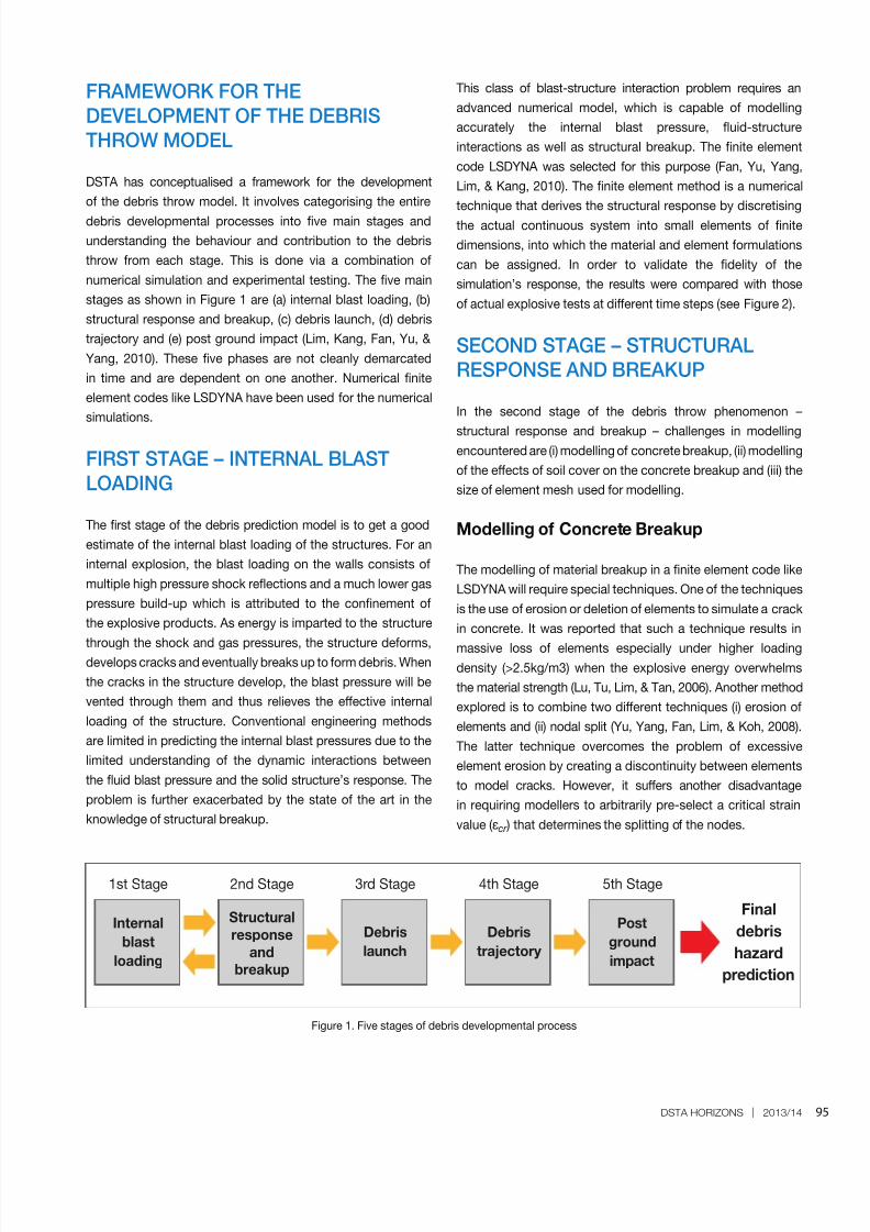
DSTA has conceptualised a framework for the development
of the debris throw model. It involves categorising the entire
debris developmental processes into ve main stages and
understanding the behaviour and contribution to the debris
throw from each stage. This is done via a combination of
numerical simulation and experimental testing. The ve main
stages as shown in Figure 1 are (a) internal blast loading, (b)
structural response and breakup, (c) debris launch, (d) debris
trajectory and (e) post ground impact (Lim, Kang, Fan, Yu, &
Yang, 2010). These ve phases are not cleanly demarcated
in time and are dependent on one another. Numerical nite
element codes like LSDYNA have been used for the numerical
simulations.
FIRST STAGE – INTERNAL BLAST
LOADING
The rst stage of the debris prediction model is to get a good
estimate of the internal blast loading of the structures. For an
internal explosion, the blast loading on the walls consists of
multiple high pressure shock reections and a much lower gas
pressure build-up which is attributed to the connement of
the explosive products. As energy is imparted to the structure
through the shock and gas pressures, the structure deforms,develops cracks and eventually breaks up to form debris. When
the cracks in the structure develop, the blast pressure will be
vented through them and thus relieves the eective internal
loading of the structure. Conventional engineering methods
are limited in predicting the internal blast pressures due to the
limited understanding of the dynamic interactions between
the uid blast pressure and the solid structure’s response. The
problem is further exacerbated by the state of the art in the
knowledge of structural breakup.
Internal
blast
loading
Structural
response
and
breakup
Post
ground
impact
1st Stage 2nd Stage 5th Stage
Final
debris
hazard
prediction
Figure 1. Five stages of debris developmental process
Debris
launch
Debris
trajectory
3rd Stage 4th Stage
This class of blast-structure interaction problem requires an
advanced numerical model, which is capable of modelling
accurately the internal blast pressure, uid-structure
interactions as well as structural breakup. The nite element
code LSDYNA was selected for this purpose (Fan, Yu, Yang,
Lim, & Kang, 2010). The nite element method is a numerical
technique that derives the structural response by discretising
the actual continuous system into small elements of nite
dimensions, into which the material and element formulations
can be assigned. In order to validate the delity of the
simulation’s response, the results were compared with those
of actual explosive tests at dierent time steps (see Figure 2).
SECOND STAGE – STRUCTURAL
RESPONSE AND BREAKUP
In the second stage of the debris throw phenomenon –
structural response and breakup – challenges in modellingencountered are (i) modelling of concrete breakup, (ii) modelling
of the eects of soil cover on the concrete breakup and (iii) the
size of element mesh used for modelling.
Modelling of Concrete Breakup
The modelling of material breakup in a nite element code like
LSDYNA will require special techniques. One of the techniques
is the use of erosion or deletion of elements to simulate a crack
in concrete. It was reported that such a technique results in
massive loss of elements especially under higher loadingdensity (>2.5kg/m3) when the explosive energy overwhelms
the material strength (Lu, Tu, Lim, & Tan, 2006). Another method
explored is to combine two dierent techniques (i) erosion of
elements and (ii) nodal split (Yu, Yang, Fan, Lim, & Koh, 2008).
The latter technique overcomes the problem of excessive
element erosion by creating a discontinuity between elements
to model cracks. However, it suers another disadvantage
in requiring modellers to arbitrarily pre-select a critical strain
value (εcr ) that determines the splitting of the nodes.

8/15/2019 Modelling the Debris Throw From a Reinforced Concrete Ammunition-storage Magazine
http://slidepdf.com/reader/full/modelling-the-debris-throw-from-a-reinforced-concrete-ammunition-storage-magazine 3/10
96 DSTA HORIZONS | 2013/14
Figure 2. Response of a reinforced concrete structure capture from a high speed video and its corresponding
numerical simulation at dierent time steps
Response and simulation
at 2ms
Response and simulation
at 4ms
Response and simulation
at 8ms
To overcome the arbitrary selection problem, a more physics-
based breakup criteria based on concrete fracture energy was
proposed by Nanyang Technological University’s Protective
Technology Research Centre. A series of laboratory teststo determine the dynamic fracture energy of concrete was
also conducted. The non-physical cohesive elements which
eectively act like glue are inserted between concrete elements
and they fail when fracture energy is attained. Therefore, there
is no longer a need for modellers to determine the breakup
failure criteria arbitrarily. The concrete breakup modelling is
illustrated in Figure 3.
Modelling of Eect of Soil Cover
Soil covered reinforced concrete magazine is one of the most
common types of magazine structure used around the worldto reduce the explosive hazards from accidental explosions.
The presence of soil will aect the debris throw prediction. The
challenge is to establish a correct material model for the soil
cover as it will aect the debris modelling in the following ways:
a) Soil adds weight to the concrete roof and slab, thereby
reducing the initial launch velocity of debris. The eective
soil thickness will not be a constant since soil spallation at its
free end will reduce the eective overburden weight on the
structure.
8/15/2019 Modelling the Debris Throw From a Reinforced Concrete Ammunition-storage Magazine
http://slidepdf.com/reader/full/modelling-the-debris-throw-from-a-reinforced-concrete-ammunition-storage-magazine 4/10
97
MODELLING THE DEBRIS THROW FROM A REINFORCED CONCRETE AMMUNITION STORAGE MAGAZINE
DSTA HORIZONS | 2013/14
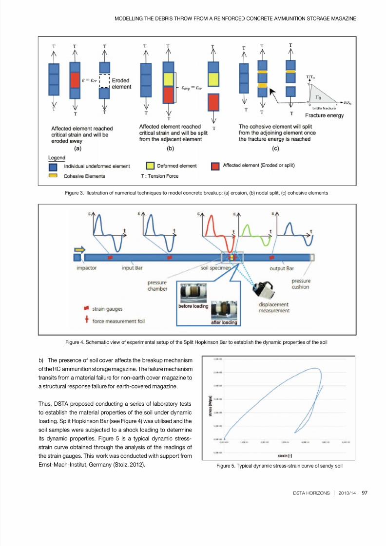
Figure 3. Illustration of numerical techniques to model concrete breakup: (a) erosion, (b) nodal split, (c) cohesive elements
Figure 4. Schematic view of experimental setup of the Split Hopkinson Bar to establish the dynamic properties of the soil
Figure 5. Typical dynamic stress-strain curve of sandy soil
b) The presence of soil cover aects the breakup mechanism
of the RC ammunition storage magazine. The failure mechanism
transits from a material failure for non-earth cover magazine to
a structural response failure for earth-covered magazine.
Thus, DSTA proposed conducting a series of laboratory tests
to establish the material properties of the soil under dynamic
loading. Split Hopkinson Bar (see Figure 4) was utilised and the
soil samples were subjected to a shock loading to determine
its dynamic properties. Figure 5 is a typical dynamic stress-
strain curve obtained through the analysis of the readings of
the strain gauges. This work was conducted with support from
Ernst-Mach-Institut, Germany (Stolz, 2012).

8/15/2019 Modelling the Debris Throw From a Reinforced Concrete Ammunition-storage Magazine
http://slidepdf.com/reader/full/modelling-the-debris-throw-from-a-reinforced-concrete-ammunition-storage-magazine 5/10
98 DSTA HORIZONS | 2013/14
With the available material model for the soil, the modelling of
soil covered ammunition magazine is illustrated in Figure 6.
Size of Mesh Used for Modelling
Debris mass and shapes are required to estimate the debris
trajectory with the initial launch conditions. As observed inFigure 3, numerical models can generate the breakup of the
concrete structure, from which modellers can collect data of
the various concrete debris. The challenge is to nd the right
mesh size as the delity of the results is highly dependent on
it. A ner mesh will allow the model to yield smaller debris
as compared to a coarser mesh. In addition, there are more
possible crack patterns in a ner mesh than those from a
coarser mesh. However, a ner mesh is computationally more
intensive and this also takes a longer time. Trade-o between
delity and speed is required to be taken into consideration in
performing numerical analysis. To overcome this, test data ondebris mass and shape is relevant and important as it allows
the calibration of the numerical model to achieve a reasonable
delity in an acceptable time.
THIRD STAGE – DEBRIS LAUNCH
At the third stage, the numerical model would be able to
generate the initial launch conditions (see Figure 7) for the
debris such as (i) the numbers, shape and size of the debris,
(ii) initial launch velocities and (iii) initial horizontal and vertical
launch angles.
FOURTH STAGE - DEBRIS
TRAJECTORY
The initial launch conditions for the debris as mentioned
previously are generated by the numerical models. With this as
input, the debris ight trajectory can be calculated. However,
the challenge is in the determination of the aerodynamiccoecients which the debris ight path trajectory is highly
Figure 6. Numerical model of the breakup of an earth covered magazine showing the soil response at (a) 6msec and (b) 20msec after detonation

8/15/2019 Modelling the Debris Throw From a Reinforced Concrete Ammunition-storage Magazine
http://slidepdf.com/reader/full/modelling-the-debris-throw-from-a-reinforced-concrete-ammunition-storage-magazine 6/10
99
MODELLING THE DEBRIS THROW FROM A REINFORCED CONCRETE AMMUNITION STORAGE MAGAZINE
DSTA HORIZONS | 2013/14
Figure 7. Modelling of the ammunition storage magazine and the initial conditions for debris launch
Figure 8. Comparison of distance travelled with or without
drag coecient
Figure 9. (a) Experimental and (b), (c) numerical modelling to derive aerodynamics coecients of concrete debris
Mass, shape, size,
initial launch velocities
and angles for all
debris generated
dependent on. An example of the inuence of the drag
coecient on the trajectory is shown in Figure 8.
The aerodynamics coecients of interests that would aect
debris trajectory are (i) Drag Coecient (CD), (ii) Lift Coecient
(CL) and (iii) Lift Coecient due to rotation (CLA). These
aerodynamics coecients are inuenced by:
a) the shape of the object
b) the Mach number of the object, where Mach number =
Speed of object/Speed of soundc) the proximity of the debris to other debris objects (“cloud
eect”), which means that some debris can decrease their drag
in the slipstream of preceding debris
d) the rotational speed of the object (Magnus eect), which
could aect the lift of the object
As concrete debris is both irregular in shape and weight, its
aerodynamic coecients are not well understood. To overcome
this challenge, a series of wind tunnel tests was conducted
at subsonic speeds (10- 265m/s) at various concrete shapes
to try to derive the aerodynamics coecients as shown in
Figure 9 (Schlüter, Sarkar, & Boopathy, 2013).
(a) (b) (c)

8/15/2019 Modelling the Debris Throw From a Reinforced Concrete Ammunition-storage Magazine
http://slidepdf.com/reader/full/modelling-the-debris-throw-from-a-reinforced-concrete-ammunition-storage-magazine 7/10
100 DSTA HORIZONS | 2013/14
From the results of the experiments and numerical modelling,
it was found that CD and CL are independent of the Reynolds
number. These coecients are dependent on the orientation
and shape of the debris. In addition, it was established that CD
increases with the speed of the debris as well. In the case of
CLA, an increase in the speed of the rotation increases the lift.
In general, CD is more signicant than CL and CLA in predicting
debris trajectory prediction.
In an internal detonation of a RC ammunition storage magazine,
the number of concrete debris generated could be in the range
of a few hundred thousand pieces. The concrete debris would
vary in both shape and size and thus a framework to assign
dierent aerodynamics coecients to individual concrete
debris was developed (see Figure 10).
FIFTH STAGE – POST GROUND
IMPACT
When the debris rst impacts the ground, it is expected to roll,
bounce and/or break up further. Limited understanding of these
physical phenomena presents a challenge. The understanding
of these phenomena is important as the debris area density
and mass distribution at the nal resting ground would be
Figure 10. Procedure for obtaining aerodynamic coecients of ying debris
aected if they are ignored. To overcome this knowledge gap,
a methodology to study these phenomena was proposed by
DSTA and Toegepast Natuurwetenschappelijk Onderzoek
(Applied Scientic Research in English) (TNO) of the
Netherlands. The methodology includes:
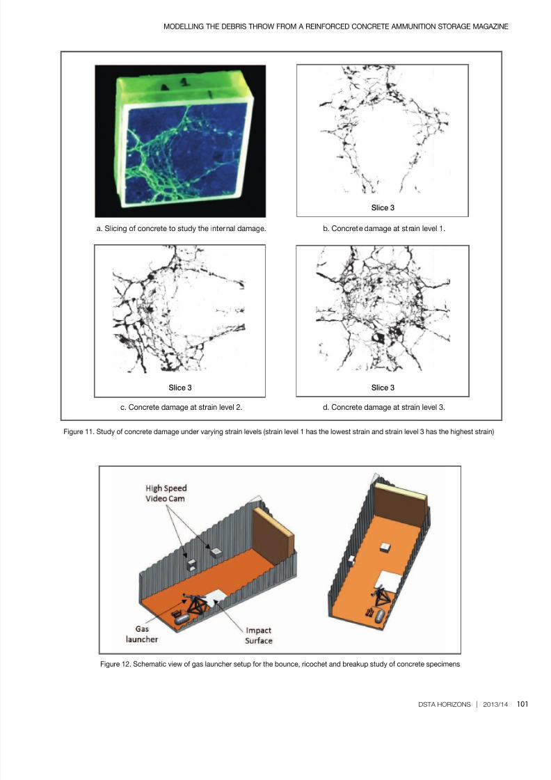
a) pre-stressing two sets of concrete specimens to a pre-
dened stress-strain state to simulate the damaged concrete
debris from a blast loading
b) using the rst set of pre-stressed concrete specimens
for slicing in order to study and quantify the damage level in
the concrete (Wong & Teoh, 2013). The lower the strain level,
the lower is the damage to the concrete specimens (see
Figure 11).
c) ring the second set of pre-stressed concrete specimens
from a specially made gas launcher to determine the breakup
characteristics (see Figure 12)
Through this study, DSTA and its collaborators hope to nd a
relationship between the concrete debris breakup upon ground
impact and its strain and damage level.
8/15/2019 Modelling the Debris Throw From a Reinforced Concrete Ammunition-storage Magazine
http://slidepdf.com/reader/full/modelling-the-debris-throw-from-a-reinforced-concrete-ammunition-storage-magazine 8/10
101
MODELLING THE DEBRIS THROW FROM A REINFORCED CONCRETE AMMUNITION STORAGE MAGAZINE
DSTA HORIZONS | 2013/14
Figure 11. Study of concrete damage under varying strain levels (strain level 1 has the lowest strain and strain level 3 has the highest strain)
Figure 12. Schematic view of gas launcher setup for the bounce, ricochet and breakup study of concrete specimens
Slice 3
Slice 3Slice 3
a. Slicing of concrete to study the internal damage. b. Concrete damage at strain level 1.
c. Concrete damage at strain level 2. d. Concrete damage at strain level 3.

8/15/2019 Modelling the Debris Throw From a Reinforced Concrete Ammunition-storage Magazine
http://slidepdf.com/reader/full/modelling-the-debris-throw-from-a-reinforced-concrete-ammunition-storage-magazine 9/10
102 DSTA HORIZONS | 2013/14
CONCLUSION
A ve-stage model outlining the debris phenomenon has been
described. Each stage has its unique challenges and dierent
sub-topics for each stage were identied and studied. This
research and development work has developed a numerical
model that is able to model the breakup of concrete ammunitionstorage magazine. It has also enhanced the understanding of
aerodynamic coecients that would aect the debris trajectory
prediction and how dierent concrete damage levels aect the
breakup of debris upon impact. These works contribute to the
development of a predictive debris throw model. As the debris
phenomenon is intrinsically complicated, future validation tests
would be required to validate the simulation results.
REFERENCES
Fan, S. C., Yu, Q., Yang, Y., Lim, H. S., & Kang, K. W. (2010,July). Study of debris throw and dispersion after breakup
of reinforced concrete structure under internal explosion.
Proceedings of the 34th Department of Defense Explosives
Safety Seminar . Portland, Oregon.
Lim, H. S., Kang, K. W., Fan, S. C., Yu, Q. J., & Yang, Y. W.
(2010, July). A review: Numerical modelling of the debris throw
of a reinforced concrete structures under internal explosions.
Proceedings of the 34th Department of Defense Explosives
Safety Seminar . Portland, Oregon.
Lu, Y., Tu, Z., Lim, H. S., & Tan, S. C. (2006, August). A
comparative numerical simulation study of concrete debris
of clamped slabs under internal blast. Proceedings of the
32nd Department of Defense Explosives Safety Seminar .
Philadelphia, Pennsylvania.
Ministry of Defence, Explosives Storage and Transport
Committee. (2008). Joint Staff Publication (JSP) 482 – MOD
explosives regulations (3rd ed.). United Kingdom: Author.
Schlüter, J. U., Sarkar, A., & Boopathy, S. R. (2013).Prediction of explosion hazards from earth covered magazine.
Singapore: Protective Technology Research Centre, Nanyang
Technological University.
Stolz, A. (2012). Dynamic soil parameters for earth covered
magazines. Freiburg, Germany: Fraunhofer Ernst-Mach-Institut.
Wong, W. Q. V., & Teoh, C. W. (2013). Quantifying damage levels
to concrete specimens. Singapore: Nanyang Technological
University.
Yu, Q. J., Yang, Y. W., Fan, S. C., Lim, H. S., & Koh, Y. H.(2008, August). A novel numerical approach for modelling
break-up of reinforced concrete structure. Proceedings of the
33rd Department of Defense Explosive Safety Seminar . Palm
Springs, California.

8/15/2019 Modelling the Debris Throw From a Reinforced Concrete Ammunition-storage Magazine
http://slidepdf.com/reader/full/modelling-the-debris-throw-from-a-reinforced-concrete-ammunition-storage-magazine 10/10
103
MODELLING THE DEBRIS THROW FROM A REINFORCED CONCRETE AMMUNITION STORAGE MAGAZINE
DSTA HORIZONS | 2013/14
BIOGRAPHY
KANG Kok Wei is a Manager (Building and
Infrastructure). He conducts and manages
research and technology projects with local
and overseas research institutes to develop
advanced protection infrastructure systems.Kok Wei is also involved in the capability
build-up of numerical modelling and has
participated in the conduct and analysis
of both local and overseas explosive trials for the past six years.
Kok Wei graduated with a Bachelor of Engineering (Civil
Engineering) degree with Honours, and further obtained a Doctor of
Philosophy (Civil Engineering) degree from the National University
of Singapore in 2005 and 2013 respectively.
KOH Yong Hong is a Programme Manager
(Building and Infrastructure). He is involvedin the project management and development
of essential storage facilities for the Ministry
of Defence and the Singapore Armed
Forces. Yong Hong has been an active
participant of the Klotz Group, an explosive
safety expert working group, since 2007,
and has assisted in the planning and analysis of explosive trials.
He is also a registered Professional Engineer in the eld of Civil
and Structure. Yong Hong graduated with a Bachelor of Science
(Civil Engineering) degree from Nanyang Technological University
in 2002. He further obtained a Master of Science (Civil Engineering)degree from the University of Florida, USA, in 2011 where he
specialises in the protection of critical infrastructures.
LIM Heng Soon is Head Technology
Development (Building and Infrastructure).
Heng Soon works with his team to nurture
and harness research into applications for
the Ministry of Defence and the Singapore
Armed Forces. Heng Soon was involved
actively in explosive safety related projects.
He was also an active participant of theKlotz Group as the point of contact for Singapore’s key delegate
to the group. He has authored numerous technical papers on
topics related to explosive safety which have been presented
in both international and local seminars like the Weapon Eects
Working Group Seminar. Heng Soon graduated with a Bachelor of
Engineering (Civil) degree from the National University of Singapore
in 1999. He further obtained a Master of Science (Civil Engineering)
degree from the Delft University of Technology, the Netherlands,
in 2005.