modeling subdivision control meshes for creating cartoon faces · modeling subdivision control...
TRANSCRIPT

Modeling Subdivision Control Meshes for Creating Cartoon Faces
Sajan Skaria∗ Ergun Akleman† Frederic I. Parke
Visualization Sciences ProgramDepartment of Architecture
Texas A&M University
Abstract
Modeling three-dimensional faces on the computer hasbeen an interesting yet challenging problem. This paperpresents a method for creating cartoon faces by using a sub-division scheme. We use set-operations for conceptual de-sign of subdivision control meshes. To ensure the quality ofthe control mesh, we have eliminated high valenced extraor-dinary vertices since smoothness of the surface decreaseswith valence. In addition, we have limited the number of ex-traordinary vertices to eliminate ripples. We have also en-sured an even structure around extraordinary vertices (Thesize of each quadrilateral in subdivided meshes are roughlysimilar). We have also developed a user-friendly interfaceto sculpt the control mesh. Using this interface we havebeen able to create a variety of cartoon faces.
1 Introduction and Motivation
Modeling three dimensional faces on the computer is avery challenging and time consuming problem. There are awide variety of ways to approach the facial modeling prob-lem. Existing function based methods for creating smoothfacial models include parametric, implicit and subdivisionsurface modeling.
One parametric surface approach is to draw a set of care-fully spaced vertical or horizontal contours of the face andthen lofting them together. The problem with this approachis that adding detail to one part of the surface will resultin the introduction of unwanted detail in other parts. Fig-ure 1 shows an example where addition of detail on the noseresults in a dense collection of iso-parametric lines on theforehead and cheek. These extra control points may pro-duce unwanted creases.∗Currently at Pixar Animation Studios.†Corresponding Author. Address: 216 Langford Center, College Sta-
tion, Texas 77843-3137. email: [email protected]. phone: +(409) 845-6599. fax: +(409) 845-4491. Supported in part by Research Council ofCollege of Architecture and Interdisciplinary Program of Texas A&M Uni-versity.
Figure 1. An example of parametric modelwith unwanted creases.
Another approach is to use parametric surface patches[15]. Using this approach the face can be modeled using agroup of independent connected patches. With careful plan-ning, a high quality model can be obtained. However, patchmodeling is time-consuming and requires a good under-standing of 3D space. A major problem with patch model-ing is maintaining boundary continuity between the patches.Figure 2 shows an example parametric patch model.
Implicit surfaces can be powerful in modeling solidshapes such as faces, since they inherently provide a sim-ple implementation of geometric operations such as unionand intersections by composition of functions [7]. Unfor-tunately, implicit methods are not computationally efficientsince computation of an implicit surface is a root findingproblem in 3D. Improvements in computational speed gen-erally require limitations on the shapes [3, 4].
Subdivision surfaces are actually polygonal surfaces thatcan approach any given parametric surface as a limit surfaceusing an iterative subdivision scheme. The power of subdi-vision schemes for modeling faces come from the fact thatthey can smooth out any 2-manifold mesh with arbitrarytopology. Subdivision control meshes are not restricted to4-sided patches like tensor product parametric surfaces.
1

Figure 2. An example of parametric patchmodel.
The goal of this research is to develop a high quality sub-division control mesh for creating cartoon faces. One prob-lem with the subdivision schemes is that smoothness of thesurface decreases with valence of extraordinary points ofcontrol mesh [35]. (Extraordinary points of are those ver-tices which have a valence (the number of edges meetingat the vertex) other than four for Catmull-Clark and Doo-Sabin schemes [8, 13].) In addition, extraordinary verticescan create surface ripples. Moreover, there may not be aneven structure around extraordinary vertices, i.e., the size ofeach quadrilateral in the subdivided mesh may be extremelydifferent. It is, therefore, essential to avoid the introduc-tion of extraordinary points wherever possible. Our controlmesh for the face is created to keep extraordinary verticesto a minimum.
The facial models from this system are not intended tobe photorealistic. This modeling tool is intended for creat-ing a variety of cartoon faces or caricatures. Detail such asnostrils, eyelids and ears must be sculpted later and are notincluded in the initial control mesh.
One of our contributions is the introduction of an effi-cient facial modeling interface for sculpting the initial con-trol mesh. This interface allows the user to manipulatethe initial control mesh by changing data in front and sideviews. This interface is both flexible and robust. Users cancreate highly exaggerated facial models and the resultingsubdivision surfaces are almost always smooth.
2 Previous Work
The first computer generated 3D faces were created byParke [27] at the University of Utah in the early 1970s. Thisfacial animation was achieved by collecting facial expres-sion polygon data from real faces using photogrammetrictechniques and interpolating between them.
Physically based facial models were first generated in
1980 by Platt [30] at the University of Pennsylvania. In1987, Waters [31] described a new approach to facial ani-mation using facial muscles. Waters et al. [32] presented amethodology to incorporate geometrically accurate polyg-onal facial representations constructed by photogrammetryof stereo facial images with generic tissue and muscle mod-els to synthesize faces capable of expressive articulation. In1993, Akimoto, et al. [1, 2] used the front and side viewsof a person to automatically modify a generic head model.Their method had two parts; extracting the features from thetwo views and automatically modifying the generic model.Lee, et al. [22, 23] presented an efficient method to generatea 3D head from image data.
Another approach to facial modeling is to allow a userto specify parameters for the facial geometry. In 1974Parke [28] created the first parametrized facial model. Pa-tel [29] offers a set of deformation parameters closely tiedto the structure of the head. Dipaola [12] provides a setof localized volumetric deformations to extend the rangeof facial types. DeCarlo et al. [9] describe a methodthat automatically generates varied geometric facial modelsbased on anthropometric statistics. Forsey uses Hierarchi-cal B-splines [16] for face design. Multiresolution methodshave also been used for the facial design and manipulation[34, 21, 19].
In this work, we use subdivision schemes to obtainsmooth facial models. The 1998 Academy Award winningshort filmGeri’s Game was one of the first movies froma major studio which successfully used subdivision surfacesfor modeling faces [11].
Subdivision schemes assume that the users provide theinitial control meshes. These initial control meshes can ei-ther be created by direct modeling or obtained by scanninga sculpted real object. A smoother version of this initialmesh without changing the original topology is obtained bysubdivision operations.
All subdivision schemes can be expressed by a set of lin-ear difference equations. More formally, each new pointis computed as a linear combination of a set of points in alocal topological region. The scheme can be written as a lin-ear systempn+1 = Apn wherepn andpn+1 are the vectorsof respectively the old points and the new points in the localtopological region andA is the transformation matrix [35].Note here, the local topological region should correspond toa simple disk (topologically). This implies that the under-lying structure must be a valid 2-manifold (or 2-manifoldwith boundary). The initial control mesh for a subdivisionscheme should not have artifacts that commonly exist incomputer graphics models such as wrongly-oriented poly-gons, intersecting or overlapping polygons, missing poly-gons, cracks, and T-junctions [5].
The existing subdivision schemes can be classified basedon three criteria [35]: (1) the type of refinement rule (e.g.

vertex insertion or corner cutting), (2) the type of gener-ated mesh (e.g. triangular or quadrilateral), (3) whetherthe scheme is approximating or interpolating. For instance,among commonly used subdivision schemes, Catmull-Clark is a vertex insertion, quadrilateral and approximat-ing scheme [8], Loop is vertex insertion, triangular and ap-proximating scheme [25] and Doo-Sabin is a corner cuttingquadrilateral and approximating scheme [13].
In this work, we use a vertex insertion, quadrilateral andapproximating (VIQA) scheme, which is a generalization ofCatmull-Clark subdivision scheme. This scheme providescontinuity control with an additional tension like parameter[33]. In a VIQA scheme the initial 2-manifold mesh canbe arbitrary. For regular meshes, VIQA can provide tensorproduct B-Spline surfaces which are widely used in model-ing.
In a VIQA subdivision scheme, the vertices with avalance other than 4 are called extraordinary vertices. (Thevalance is the number of edges meeting at the vertex.) Toobtain high-quality VIQA surface, it is necessary to avoidextraordinary vertices since they may create uneven poly-gon sizes and ripples. Use of polygons which are not 4-sided also results in extraordinary vertices as shown in Fig-ure 3. To avoid such secondary extraordinary vertices, non-quadrilateral faces should be avoided.
Figure 3. Vertex Insertion type subdivision ona mesh containing a 6-sided face, resulting inthe introduction of an extraordinary point.
3 Designing The Initial Mesh
Since the quality and topology of the smooth surface re-sulting from subdivision rules depend greatly on the initialcontrol mesh, theoretical assurance of the quality of the ini-tial control mesh is extremely important. In other words, theprocess of obtaining the initial control mesh must be robustand guarantee valid 2-manifolds.
The method adopted in this work is to use set opera-tions to design an initial control mesh for VIQA subdivi-sion. Set operations are very intuitive in designing such aninitial mesh. Any convex region on a face, such as the nose
or chin, can be approximated by performing an intersectionoperation of its side, top and front views. Once we have anapproximate shape for each convex region of the face, wecan perform a union operation of all these individual shapesto get a final model that will be used as the initial controlmesh.
However, the problem with set operations is that they canresult in non-manifold topologies, non-quadrilateral facesand lamina topology. They can even create free points andfloating edges. Moreover, many existing data structures inmesh modeling are specifically developed so that they canrepresent non-manifold surfaces resulting from set opera-tions. They do not guarantee valid 2-manifold surfaces. Be-cause of this fundamental problem, the process of obtainingthe initial control mesh can result in unwanted artifacts suchas wrongly-oriented polygons, intersecting or overlappingpolygons, missing polygons, cracks, and T-junctions.
Another problem with set operations is that they can re-sult in many extraordinary vertices and non-quadrilateralfaces. For instance, as shown in Figure 4 even in an inter-
Figure 4. Incorrect alignment of meshes re-sulting in introduction of non-quadrilaterals.
section of two simple shapes (extruded polygons), we canend up with non-quadrilateral polygons. However, with acareful alignment of the same shapes we can obtain a shapeconsisting of only quadrilaterals as shown in Figure 5 (Notethat we cannot avoid extraordinary vertices completely).
Figure 5. Correct alignment of shapes.
Because of the problems we mentioned above, we haveused set operations only in the design stage. We de-signed the initial control mesh with a great care to en-sure that the resulting mesh is a 2-manifold and that ithas minimum number of extraordinary vertices and non-quadrilateral faces.

We have identified convex regions that can be createdas an intersection of extruded polygons. We observed thata cartoon face broadly consists of six convex regions; theforehead, the cheek, the nose, the chin, the upper lip and thelower lip. The shape of each convex region can be approx-imated by an intersection of extruded side, front and topviews. After creating these convex regions separately, wecarefully placed them together and performed a union op-eration to get the initial control mesh. The union operationcreates polygons with lamina topology at the faces were theregions touch each other. These polygons are deleted fromthe control mesh to make it subdivision friendly.
3.0.1 Designing Convex Regions
As mentioned before, we divide the face into six convexregions. To create a convex region using set intersection,we use side, front and top views. We first determine whichview provides the maximum information about the shape ofthe region. In most cases this is the side view. Next weidentify whether intersecting this mesh with the top viewor the front view gives us additional information about theshape. The following subsections discuss how each regionis constructed.
Forehead: The approximate shape for the forehead is ob-tained by performing an intersection operation of the ex-truded side view and the extruded front view as shown inFigure 6. Both side and front views are 10 sided convexpolygons. The bottom-most section forms the top part of theeye socket. The section above this gives shape to the eye-brow. The next section forms the major plane of the fore-head and the back of the head while the top section givesthe curve for the top of the head.
Figure 6. Forehead: side view, front view andfinal mesh.
The front view of the forehead is created so that eachvertex lies exactly in line with an associated point on theside view. If any of these vertices do not lie in the samehorizontal plane as vertices on the side view, we can end upwith non quadrilateral polygons as shown in Figure 4.
Cheek: The cheek is also obtained by performing an in-tersection of extruded side and front views as shown in Fig-ure 7. Both side and front views are also 10 sided convexpolygons. The bottom-most section connects the lower lipto the back of the jaw. Similarly the next section connectsthe upper lip to the back of the head. The third section con-nects the base of the nose tothe back of the head. The finalsection makes up the bottom part of the eye socket.
Figure 7. Cheek: side view, front view andfinal mesh.
Nose: The nose is an intersection of the extruded sideview and extruded top view as shown in Figure 8. The sideview of the nose is made up of three quadrilaterals. Thesection in the middle defines thehookof the nose. It alsoconnects the nose to a section of the cheek. The section atthe bottom of the side view is used to control the tip of thenose. The section at the top connects the nose to the eyesockets and forehead. Because of the shape of the nose, theapproach is to use the top view for further shaping of thenose. The top view helps to taper the nose. This operationhelps shape the nose without adding unnecessary complex-ity.
Figure 8. Nose: side view, top view and finalmesh.
This nose however introduces two new vertices to theforehead when they are later attached. As shown in Fig-ure 9 this attachment creates an extraordinary point whenthe mesh is later subdivided. However this extraordinarypoint does not create a visible unevenness on the foreheadand hence we leave it untouched. While change to the topol-ogy of the forehead might remove this extraordinary point,it will also increase the complexity of the mesh.

Figure 9. Extraordinary point on forehead.
Chin: The chin is obtained by intersecting the extrudedside view and the extruded front view as shown in Fig-ure 10. Both side and front views are also 10 sided convexhexagons. The side view of the chin is made up of two sec-tions. The bottom sectionprovides the roundness of the chinwhen the control mesh is later subdivided. The top sectionattaches the chin to the bottom of the cheek.
Figure 10. Chin: side view, front view and finalmesh.
Upper Lip: The creation of the upper lip is a little morecomplicated than the previous regions. The upper lip couldbe modeled as a single block. However to actually be ableto recognize the mesh as an approximation for the upperlip, the depression in the middle of the lip is important. Toaccommodate this depression, one half of the upper lip ismodeled and then mirrored to obtain the second half.
To obtain the control mesh for the upper lip we do an in-tersection operation of the side, front and an angular view.This obtains two sloping surfaces; one sloping from themiddle of the upper lip towards the cheek and the other slop-ing from the base of the nose to the edge of the mouth.
Performing the intersection of the extruded side and frontviews gives us the slope from the base of the nose to theedge of the mouth as shown in Figure 11.
To get the slope from the middle of the upper lip towardsthe cheek, we might try intersecting this mesh with the topview. However this introduces an unwanted edge in a veryunintuitive direction as shown in Figure 12
Rather, we intersect the mesh obtained from the side andfront views, with an angular view, which is oriented at aboutforty five degrees. This slopes the lip towards the cheek asshown in Figure 13.
Figure 11. Intersection of side and front upperlip views.
Figure 12. Intersection of side, front and topupper lip views results an unwanted edge.
Figure 13. Intersection of side, front and an-gular upper lip views.

The final mesh for the upper lip is shown in Figure 14.
Figure 14. Upper lip: side view, front view,angular view and final mesh.
While the control mesh we obtained is made up ofquadrilaterals, a few new extraordinary points are intro-duced when the upper lip is combined with the rest of theface. One such extraordinary point is underneath the nose.The others are at the corner of the mouth and at the cornerof the nose. The one underneath the nose is hidden fromview in most cases.
Lower Lip: The lower lip is easier to create than the up-per lip. Performing an intersection between the extrudedside view and extruded front view gives a mesh for the lowerlip. This mesh is again made up of quadrilaterals. Figure 15shows the final control mesh for the lower lip.
Figure 15. Lower lip: side view, front view andfinal mesh.
3.0.2 The Base Mesh
Once we have the individual control meshes for each region,they are positioned as shown in Figure 16. The individualcontrol meshes are placed so that their surfaces fall exactlyon associated surfaces of the neighbouring mesh. Thus, thebottom of the forehead falls exactly on the top of the cheek.Similarly, the bottom of the cheek falls exactly on the top ofthe chin. Even a very small misalignment can result in theintroduction of extra polygons which may not be quadrilat-erals. The base mesh is then created by performing a unionoperation of all six convex regions. This, however, createspolygons with lamina topology at the faces were the regions
meet. These polygons are deleted from the control mesh tomake it subdivision friendly.
Figure 16. Positioning of regions to create fi-nal mesh.
Although the base mesh is mostly quadrilaterals, thereare a few polygons which are not 4-sided. However, theseare either well hidden or are at positions where they do notcreate major problems when the mesh is subdivided. Thebase mesh satisfies all the conditions required for successfulconversion to a subdivision surface. Figure 17 shows thefinal VIQA subdivision control mesh for the face.
This base mesh contains sixty-nine polygons. Other thanquadrilaterals, the control mesh contains one pentagon, twohexagons and one heptagon. These polygons introduce ex-traordinary points on the mesh. In addition, there exist fourvertices with a valence of six. Fortunately, these are eitherat positions where they are fairly hidden, such as under-neath the nose, or at places where they did not create muchproblems, such as the corner of the mouth.
Figure 17. The control mesh.

3.1 Developing the Interface
Set operations were used while constructing the initialcontrol mesh because it was easier to visualize each regionin two dimensions rather than in three dimensions. By us-ing this organized approach, the mesh can be reproducedmore easily than if it was constructed by laying out pointsin space. While set operations are useful during the con-struction of the initial mesh, they do not work well in aninteractive environment. There are several cases where setoperations can fail when the regions are being manipulated.Because of this, the subdivision control mesh is created asone single polygonal model whose vertices can be directlymanipulated in the interface.
One of the contributions of this work is the introductionof a user-friendly interface. In this approach users can ma-nipulate controls directly on profiles of the side and frontviews of the mesh. Since the topology of the mesh remainsthe same no matter how much the user exaggerates the re-gions on the face, the mesh is guaranteed to remain subdi-vision friendly. The conceptual design of this interface isshown in Figure 18.
Figure 18. Design for modeling interface.
4 Implementation
There were several alternatives for implementing this fa-cial modeling tool. One option was to implement it usingC++ and OpenGL. However this would require spendingmost of the time writing basic display operations unrelatedto the core idea. Another option was to use an existing mod-eling package for the basic operations. The facial modelingtool could then be written as a plug-in. Alias/Wavefront’sMaya is such a modeling and animation package. Maya hasthe advantage of having a scripting language, which sup-ports the development of plug-ins.
4.1 The Modeling Interface
The initial approach for the interface was to provide theuser with a set of sliders which would control the shapes ofthe different regions on the face. This was soon discardedbecause it was not intuitive. We realized that artists gener-ally prefer working directly on the model. So a new inter-face was developed which allows the user to directly movepoints on the generic mesh. A dialog box also provides ad-ditional functionality to the user. Figure 19 shows the de-veloped Maya interface.
Figure 19. Modeling interface.
This interface consists of two parts. The first part is a setof three windows where the user manipulates the genericmesh by dragging locators. There are two groups of loca-tors. Locators for manipulating the side view and locatorsfor manipulating the front view. Each locator in turn is par-ented to two clusters of vertices. One cluster contains rel-evant points on the generic polygonal mesh. The secondcluster contains relevant point(s) on a curve that defines theprofile of the mesh. A cluster is used just so that we cangroup a set of vertices and parent it to a locator.
The locators in the side panel are allowed motion onlyalong the z and y axes. The locators in the front panel areallowed to move only along the x axis. Another level ofcontrol is provided to the user by creating a group of largerlocators in both the side and front panels. Each of the largerlocators are connected to a small group of the original lo-cators. For example there is a large locator connected tothe two smaller locators defining the tip of the nose in theside panel. A user therefore has a higher level of control inresizing the tip of the nose by dragging this locator.
Different types of objects can be hidden in the different

panels in Maya. However, it is not possible to hide differentgroups of the same object in different panels. This causesthe locators that control the side view to be visible in thefront panel and vice versa. This might confuse the user. Theproblem is solved by scaling the locators in the side view tozero in the x direction. Similarly all the locators in the frontview are scaled to zero in the z direction so that they are notvisible in the side panel.
4.2 The Dialog Box
The second part of the interface is a helper dialog box.As shown in Figure 20 this dialog box offers several featuresto assist the modeling process.
Figure 20. The helper dialog box.
The Create Subdivision Surface button con-verts the polygonal mesh into a subdivision surface. TheMEL command that converts the polygonal mesh intoa subdivision surface takes two important parameters.maxPolyCount sets the maximum number of faces theoriginal surface can have to successfully convert it to a sub-division surface. In our modeling tool the number of faceson the base mesh always remains constant at sixty nine facesand hence this value is easily set. The second parameter ismaxEdgesPerVert , which sets the maximum number ofedges each vertex in the base mesh can have to successfullyconvert to a subdivision surface. While most of the verticeshave four edges coinciding there are a few unavoidable ex-traordinary vertices. The corner of the mouth where theupper lip, lower lip and the cheek meet has six edges com-ing together. This is the maximum number of edges comingtogether at a vertex on our base mesh. Figure 21 shows asubdivision surface created from the generic face model.
TheSmooth button allows the user to convert the polyg-onal base mesh into a smoother polygonal mesh. Mayamodifies the topology of the polygonal object by smooth-ing out vertices and their connected edges. The result is apolygonal mesh subdivided using the VIQA scheme. How-ever this object will remain a polygonal mesh and Maya’s
Figure 21. Control mesh and correspondingsubdivision surface.
subdivision operations cannot be performed on this surface.The important inputs to the MEL command that does
polygonal smoothing aredivisions andcontinuity .The flagdivisions specifies the number of times Mayaperforms the smoothing operation. Maya allows this pa-rameter to be one, two, three or four. The higher the value,the smoother the object.Continuity determines the de-gree of smoothness. This can be any value from 0.0 to 1.0.While modeling a childs face, its a good idea to increaseboth continuity and divisions . This will ensurethat the model is as smooth as possible. While modelingan adult male face, these parameters whould be kept as lowas possible. The Figure 22 shows the base mesh smoothedwith different values of continuity and divisions.
Figure 22. Smooth polygonal mesh show-ing different values for divisions andcontinuity .
The Reset Mesh button is provided so that the usercan revert back to the original control mesh if the subdivi-
sion surface or smoothed polygonal mesh is unsatisfactory.Two edit boxes are provided to allow the user to load side
and front image planes as reference while modeling.The user might unintentionally change settings or lay-
out in Maya. TheDefault Environment button willoverride changes and take the user back to the original en-vironment.
Once the user is satisfied with the model (subdivisionsurface or smoothed polygonal mesh), it may be exportedusing theExport Model button.
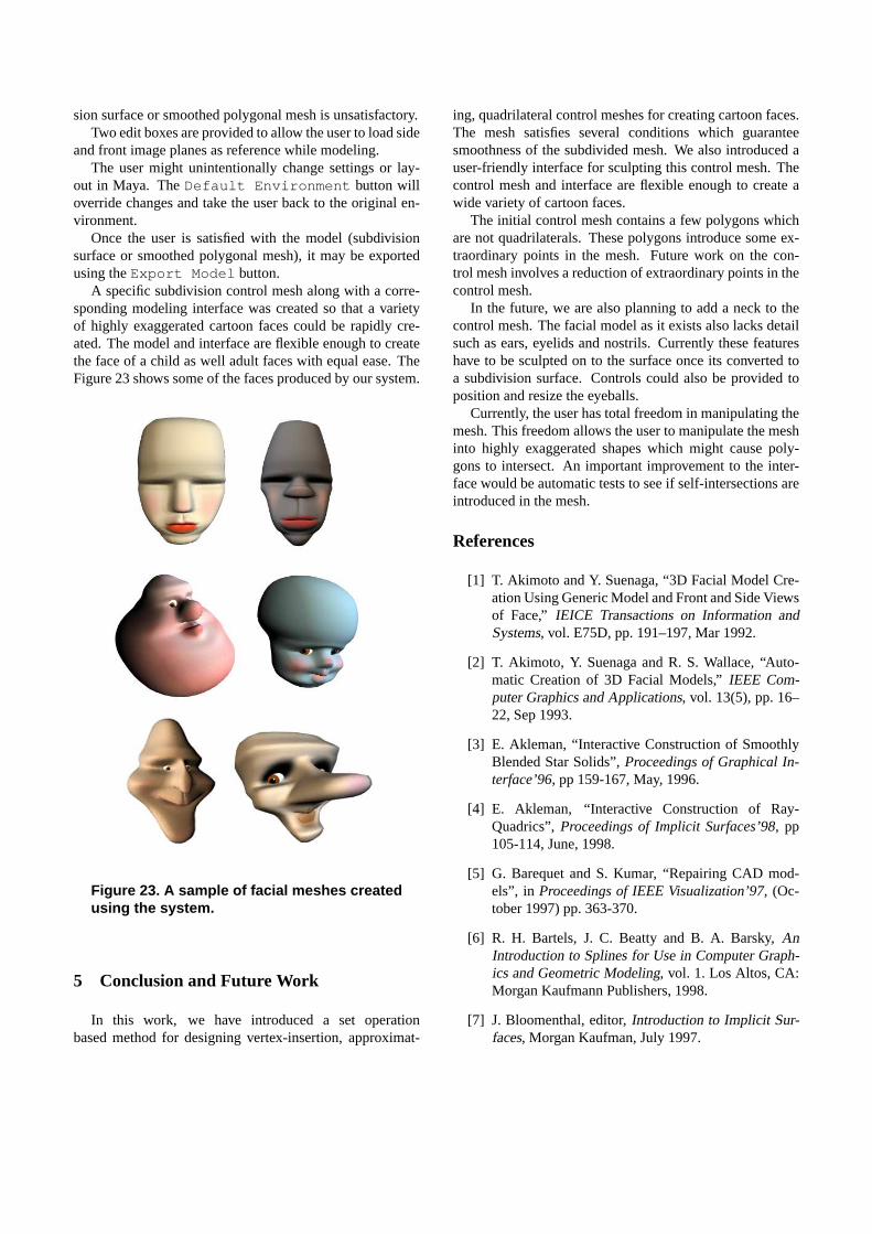
A specific subdivision control mesh along with a corre-sponding modeling interface was created so that a varietyof highly exaggerated cartoon faces could be rapidly cre-ated. The model and interface are flexible enough to createthe face of a child as well adult faces with equal ease. TheFigure 23 shows some of the faces produced by our system.
Figure 23. A sample of facial meshes createdusing the system.
5 Conclusion and Future Work
In this work, we have introduced a set operationbased method for designing vertex-insertion, approximat-
ing, quadrilateral control meshes for creating cartoon faces.The mesh satisfies several conditions which guaranteesmoothness of the subdivided mesh. We also introduced auser-friendly interface for sculpting this control mesh. Thecontrol mesh and interface are flexible enough to create awide variety of cartoon faces.
The initial control mesh contains a few polygons whichare not quadrilaterals. These polygons introduce some ex-traordinary points in the mesh. Future work on the con-trol mesh involves a reduction of extraordinary points in thecontrol mesh.
In the future, we are also planning to add a neck to thecontrol mesh. The facial model as it exists also lacks detailsuch as ears, eyelids and nostrils. Currently these featureshave to be sculpted on to the surface once its converted toa subdivision surface. Controls could also be provided toposition and resize the eyeballs.
Currently, the user has total freedom in manipulating themesh. This freedom allows the user to manipulate the meshinto highly exaggerated shapes which might cause poly-gons to intersect. An important improvement to the inter-face would be automatic tests to see if self-intersections areintroduced in the mesh.
References
[1] T. Akimoto and Y. Suenaga, “3D Facial Model Cre-ation Using Generic Model and Front and Side Viewsof Face,” IEICE Transactions on Information andSystems, vol. E75D, pp. 191–197, Mar 1992.
[2] T. Akimoto, Y. Suenaga and R. S. Wallace, “Auto-matic Creation of 3D Facial Models,”IEEE Com-puter Graphics and Applications, vol. 13(5), pp. 16–22, Sep 1993.
[3] E. Akleman, “Interactive Construction of SmoothlyBlended Star Solids”,Proceedings of Graphical In-terface’96, pp 159-167, May, 1996.
[4] E. Akleman, “Interactive Construction of Ray-Quadrics”,Proceedings of Implicit Surfaces’98, pp105-114, June, 1998.
[5] G. Barequet and S. Kumar, “Repairing CAD mod-els”, in Proceedings of IEEE Visualization’97, (Oc-tober 1997) pp. 363-370.
[6] R. H. Bartels, J. C. Beatty and B. A. Barsky,AnIntroduction to Splines for Use in Computer Graph-ics and Geometric Modeling, vol. 1. Los Altos, CA:Morgan Kaufmann Publishers, 1998.
[7] J. Bloomenthal, editor,Introduction to Implicit Sur-faces, Morgan Kaufman, July 1997.

[8] E. Catmull and J. Clark, “Recursively Generated B-Spline Surfaces on Arbitrary Topological Meshes,”Computer Aided Design, vol. 10, pp. 350–355, Sep1978.
[9] D. DeCarlo, D. Metaxas and M. Stone, “An Anthro-pometric Face Model using Variational Techniques,”Computer Graphics Proceedings, Annual Confer-ence Series, pp. 67–74, 1998.
[10] T. DeRose, “Subdivision Surfaces,”ComputerGraphics World, vol. 21(2), pp. 22–22, Feb 1998.
[11] T. DeRose, M. Kass and T. Truong, “SubdivisionSurfaces in Character Animation,”SIGGRAPH ’98Proceedings, July 1998.
[12] S. DiPaola, “Extending the Range of Facial Types,”Journal of Visualization and Computer Animation,vol. 2(4), pp. 129–131, 1991.
[13] D. Doo and M. Sabin, “Behaviour of Recursive Sub-division Surfaces Near Extraordinary Points,”Com-puter Aided Design, vol. 10, pp. 356–360, Sep 1978.
[14] M. Dooley, “Anthropometric Modeling Programs - ASurvey,”IEEE Computer Graphics and Applications,vol. 2, pp. 17–25, Nov 1982.
[15] G. Farin, “Curves and Surfaces for Computer AidedGeometric Design,” Academic Press, 1996.
[16] D. R. Forsey and R. H. Bartels, “Hierarchical B-Spline Refinement,”Proceedings SIGGRAPH ’88,pp. 189-199, 1988.
[17] T. S. Huang and L. A. Tang, “3D Face Modelingand its Applications,”International Journal of Pat-tern Recognition and Artificial Intelligence, vol. 10,pp. 491–520, Aug 1996.
[18] H. H. S. Ip and L. J. Yin, “Constructing a 3D Individ-ualized Head Model From Two Orthogonal Views,”Visual Computer, vol. 12, pp. 254–266, 1996.
[19] L. Kobbelt, S. Campagna, J. Vorsatz, H. P. Seidel,“Interactive Multi-resolution Modeling on ArbitraryMeshes,”Proceedings SIGGRAPH ’98, pp. 105-114,1998.
[20] C. Landreth, “Faces With Personality: ModelingFaces That Exude Personality When Animated,”Computer Graphics World, vol. 19(2), pp. 58–61,Feb 1996.
[21] A. W. F. Lee, W. Swelsedens, P. Schroder, L. Cowsarand D. Dobkin, “MAPS: Multiresolution AdaptiveParameterezation of Surfaces,”Proceedings SIG-GRAPH ’98, pp. 95-104, 1998.
[22] Y. Lee, D. Terzopoulos and K. Waters, “ConstructingPhysics-Based Facial Models of Individuals,”Graph-ics Interface ’93, pp. 1–8, May 1993.
[23] Y. Lee, D. Terzopoulos and K. Waters, “RealisticFace Modeling for Animation,”Proceedings SIG-GRAPH ’95, pp. 55–62, 1995.
[24] W. S. Lee and N. M. Thalmann, “Head Model-ing From Pictures and Morphing in 3D With ImageMetamorphosis Based on Triangulation,”Modellingand Motion Capture Techniques For Virtual Environ-ments, vol. 1537, pp. 254–267, 1998.
[25] C. Loop, “Smooth Subdivision Surfaces Based onTriangles,” Master’s thesis, Department of Mathe-matics, University of Utah, 1987.
[26] H. Morikawa, E. Kondo and H. Harashima, “3DFacial Modeling for Model-Based Coding,”IE-ICE Transactions on Communications, vol. E76B,pp. 626–633, Jun 1993.
[27] F. I. Parke and K. Waters,Computer Facial Anima-tion, vol. 1. Wellesley, Mass.: A. K. Peters, 1996.
[28] F. I. Parke, “Parameterized Models For Facial Ani-mation,”IEEE Computer Graphics and Applications,vol. 2(9), pp. 61–68, 1982.
[29] M. Patel and P. Willis, “FACES:The Facial Anima-tion Construction and Editing System,”Eurographics’91, 1991.
[30] S. M. Platt, “A System For Computer Simulationof the Human Face,” Master’s thesis, The MooreSchool, University of Pennsylvania, Philadelphia,1980.
[31] K. Waters, “A Muscle Model For Animating Three-Dimensional Facial Expressions,”Computer Graph-ics, vol. 21(4), pp. 17–24, Jul 1987.
[32] K. Waters and D. Terzopoulos, “The Computer Syn-thesis of Expressive Faces,”Philosophical Trans-actions of the Royal Society of London Series B-Biological Sciences, vol. 335(1273), pp. 87–93, Jan1992.
[33] Maya. Alias—Wavefront, Toronto, Canada, 1999.
[34] D. Zorin, P. Schroder and W. Sweldens, “InteractiveMultiresolution Mesh Editing,”Proceedings SIG-GRAPH ’97, pp. 259-168, 1997.
[35] D. Zorin, editor,Subdivision for Modeling and An-imation, ACM SIGGRAPH’2000 Course Notes no.23, July, 2000.