modeling and characterization of piezoelectrically ...staff.bath.ac.uk/msscrb/giddings_isaf.pdfbowen...
TRANSCRIPT

IEEE TransacTIons on UlTrasonIcs, FErroElEcTrIcs, and FrEqUEncy conTrol, vol. 58, no. 9, sEpTEmbEr 2011 1737
0885–3010/$25.00 © 2011 IEEE
Modeling and Characterization of Piezoelectrically Actuated Bistable
Compositeschristopher rhys bowen, peter F. Giddings, aki I. T. salo, and Hyunsun alicia Kim
Abstract—This paper develops and validates a finite-element model to predict both the cured shape and snap-through of asymmetric bistable laminates actuated by piezoelectric macro fiber composites attached to the laminate. To fully describe piezoelectric actuation, the three-dimensional compliance [sij], piezoelectric [dij], and relative permittivity [εij] matrices were formulated for the macro fiber actuator. The deflection of an actuated isotropic aluminum beam was then modeled and com-pared with experimental measurements to validate the data. The model was then extended to bistable laminates actuated using macro fiber composites. Model results were compared with experimental measurements of laminate profile (shape) and snap-through voltage. The modeling approach is an im-portant intermediate step toward enabling design of shape-changing structures based on bistable laminates.
I. Introduction
For aerospace applications, the use of morphing sur-faces and smart materials can reduce drag [1], pro-
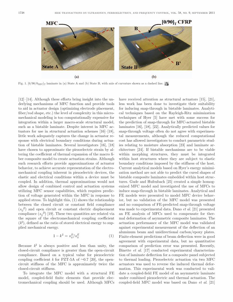
vide load alleviation, and enable aerodynamic control [2]. asymmetric bistable laminates have been proposed as a materials solution for morphing and shape chang-ing components [3], [4]. bistable composites can maintain two significantly different shapes without a continuous energy input, requiring only actuation to initiate a transi-tion between states. piezoelectric materials, such as macro fiber composites (mFcs) [3], have been used to induce snap-through bistable composites from one stable state to another. Fig. 1 shows the two stable states, state a and state b, of a bistable carbon fiber reinforced plastic (cFrp) combined with a piezoelectric mFc. The cFrp is an asymmetric [0/90]T laminate for which an anisotropy of the coefficient of thermal expansion leads to a residual stress on cooling from the cure temperature and induces a curvature and the existence two stable equilibrium states.
The cured shape and snap-through behavior of bistable laminates without integrated piezoelectric materials have been investigated with analytical [5] and finite-element (FE) techniques [6]. attempts to predict piezoelectric-in-duced snap-through of a combined cFrp-mFc composite
from one stable state to another have proven more chal-lenging because of the multi-physics nature of the prob-lem. This paper presents a homogenized coupled multi-physics model of mFc-based piezoelectric actuation and integrates it with a bistable cFrp laminate model. after an initial review of existing work to date on bistable com-posite and piezoelectric actuation in section II, the paper will develop the compliance [sT
ij], piezoelectric [dij] and relative permittivity [εT
ij] matrices of the mFc in section III. The approach is then validated by modeling a simple isotropic beam under open and closed circuit conditions in section IV. Finally, the model will be extended to in-clude an mFc attached to a bistable laminate in section V. both the cured shape and snap-through actuation of the piezoelectrically actuated cFrp-mFc combination will be modeled and compared with experimental mea-surements.
II. background
A. MFC Construction
The actuators used were from smart materials GmbH (dresden, Germany) and consist of polycrystalline piezo-electric ceramic rods. copper interdigitated electrodes are attached to the upper and lower surfaces to apply an electric field parallel to the rod length. The piezoelectric ceramic is a lead zirconate titanate (pZT) material, in this case pZT-5a because this is a soft pZT which exhibits high piezoelectric d33 and d31 coefficients, i.e., a high strain per unit electric field [7]. To maximize the strain per unit electric field, the poling direction of the pZT is aligned along the rod length using the interdigitated electrodes. This ensures that the actuation strain is generated via the d33 coefficient, which is typically twice the d31 coefficient [8], [9]. The electrode arrangement also improves damage tolerance; because the electric field is applied at regular intervals along the rod length, any damage or fracture of the rod or electrode merely reduces the functionality of a small region surrounding the defect and does not signifi-cantly reduce global actuator performance [9].
B. MFC Modeling Approaches and Bistable Actuation
Efforts to model the microscopic behavior of the con-stituent materials of the mFc are ongoing, with several workers using both FE [10], [11] and analytical techniques
manuscript received december 31, 2010; accepted march 27, 2011. We wish to acknowledge the financial support of Great Western research (GWr) and airbus.
c. r. bowen, p. F. Giddings, and H. a. Kim are with the materials research centre, department of mechanical Engineering, University of bath, bath, UK.
a. I. T. salo is with sport and Exercise science, University of bath, bath, UK.
digital object Identifier 10.1109/TUFFc.2011.2011
IEEE TransacTIons on UlTrasonIcs, FErroElEcTrIcs, and FrEqUEncy conTrol, vol. 58, no. 9, sEpTEmbEr 20111738
[12]–[14]. although these efforts bring insight into the un-derlying mechanisms of mFc function and provide tools to aid in actuator design (optimizing electrode placement, fiber/rod shape, etc.) the level of complexity in this micro-mechanical modeling is too computationally expensive for integration within a larger macro-scale structural model, such as a bistable laminate. despite interest in mFc ac-tuators for use in structural actuation schemes [16]–[18], little work adequately captures the change in actuator re-sponse with electrical boundary conditions during actua-tion of bistable laminates. several investigators [16], [18] have chosen to approximate the piezoelectric strain by al-tering the coefficient of thermal expansion of the macro fi-ber composite model to create actuation strains. although such research efforts provide approximations of actuator behavior, to achieve accurate representation of the electro-mechanical coupling inherent in piezoelectric devices, the elastic and electrical conditions within a device must be coupled. In addition, thermal approximations would not allow design of combined control and actuation systems utilizing mFc sensor capabilities, which requires predic-tion of voltage generated within the mFc in response to applied stress. To highlight this, (1) shows the relationship between the closed circuit or constant field compliance (sij
E) and open circuit or constant electric displacement compliance (sij
D) [19]. These two quantities are related via the square of the electromechanical coupling coefficient (k2), defined as the ratio of stored electrical energy to sup-plied mechanical energy.
1 2− =k s sijD ijE/ (1)
because k2 is always positive and less than unity, the closed-circuit compliance is greater than the open-circuit compliance. based on a typical value for piezoelectric coupling coefficient k for pZT-5a of ~0.7 [20], the open-circuit stiffness of the mFc is approximately twice the closed-circuit stiffness.
To integrate the mFc model with a structural FE model, coupled-field finite elements that provide elec-tromechanical coupling should be used. although mFcs
have received attention as structural actuators [15], [21], less work has been done to investigate their suitability for inducing snap-through in bistable laminates. analyti-cal techniques based on the rayleigh-ritz minimization techniques of Hyer [5] have met with some success for the prediction of snap-through for mFc-actuated bistable laminates [16], [18], [22]. analytically predicted values for snap-through voltage often do not agree with experimen-tal measurements, although the reduced computational cost has allowed investigators to conduct parametric stud-ies relating to moisture absorption [23] and laminate ar-chitecture [24]. If bistable mechanisms are to be viable within morphing structures, they must be integrated within host structures where they are subject to elastic boundary conditions imposed by the stiffness of the host. current analytical models based on Hyer’s energy minimi-zation method are not able to predict the cured shapes of bistable composite laminates embedded within host struc-tures. Gude and Hufenbach [25] created a simple homog-enized mFc model and investigated the use of mFcs to induce snap-through in bistable laminates. analytical and FE models were presented to model mFc device behav-ior, but no validation of the mFc model was presented and no comparison of FE-predicted snap-through voltage was made to experimental data. dano et al. [21] presented an FE analysis of mFcs used to compensate for ther-mal deformation of asymmetric composite laminates. The actuation performance of the mFc model was validated against experimental measurement of the deflection of an aluminum beam and unidirectional carbon/epoxy plates. Finite-element predictions of beam deflection were in good agreement with experimental data, but no quantitative comparison of prediction error was presented. recently, binette et al. [17] conducted experimental characteriza-tion of laminate deflection for a composite panel subjected to thermal loading. piezoelectric actuation via two mFc actuators was used to reverse the induced thermal defor-mation. This experimental work was conducted to vali-date a coupled-field FE model of an asymmetric laminate under combined piezoelectric and thermal actuation. The coupled-field mFc model was based on dano et al. [21]
Fig. 1. [0/90/0mFc]T laminate in (a) state a and (b) state b, with axis of curvature shown as a dashed line.

bowen et al.: modeling and characterization of piezoelectrically actuated composites 1739
and shared the same set of material properties to repre-sent the mFc. system behavior under isothermal piezo-electric actuation and combined thermal-piezo loading was predicted using the FE model developed. In the case of combined thermal and piezoelectric loading prediction, accuracy varies between 4% and 31%.
Following an attempt to model bistable composite lam-inates using the commercial ansys FE analysis software (release V5.5.2, ansys Inc., canonsburg, pa), Gude and Hufenbach [25] attempted to model the snap-through of a bistable composite laminate using 8-node layered solid elements (solId46) to represent the laminate and 8-node coupled-field brick elements (solId5) for the mFc. The [0/90]T laminate was manufactured from an unidentified pre-preg material using T300 carbon fiber reinforcement; it measured 150 × 150 × 0.5 mm. a smart materials mFc-8557p1 actuator was bonded to its upper surface. The element types used for both bistable composite and mFc volumes were linear solid elements [25]. both element types approximate the displacement field between nodes using linear interpolation. This first-order approximation to displacement introduces numerical errors in the analy-sis of highly curved structures [26]. because no details of mesh density were given in the work, it is not possible to determine if element size was reduced to minimize these er-rors. Furthermore, the solId46 element is unsuitable for modeling curved structures. When the solId46 element is deformed, as occurs in highly curved bistable laminates, the element stiffness matrix is formulated assuming the element coordinate system remains parallel to the original coordinate system of the undeformed element [26]. no pre-dicted snap-through voltage was presented and no com-parison between the FE solution and either experimental data or analytical predictions was made. The authors sim-ply state that snap-through was predicted. It should be noted that the analytical model presented by Gude et al. [25] in addition to the FE model did not agree well with experimental data contained within the work. analytical-ly predicted values for snap-through voltage deviated from those observed in experiment by 130% (1260 V predicted, 526 V observed). Gude et al. [27] very recently presented a highly novel semi-analytical, geometrically non-linear sim-ulation model using the rayleigh-ritz method with good agreement with experiments (snap-through voltage). an-sys FE analysis was also examined by the authors and it was concluded that meshing the laminate and actuator with shell elements and simulating the piezoelectric strain of the mFc by thermal expansion was more appropriate for fast solution times.
portela et al. [16] presented an analytical technique and an FE model using abaqUs/EXplIcIT (simulia, provi-dence, rI) to predict snap-through voltage for an mFc-actuated bistable laminate. The FE model approximated the behavior of the mFc by applying a different thermal load to the mFc elements than the bistable composite elements. by scaling the coefficient of thermal expansion of the mFc elements to match the strain per unit elec-tric field value of the mFc (d33), a correlation between
temperature change within the mFc elements and drive voltage was obtained. In addition, portela et al. [16] pre-dicted the effect of moisture on laminate curvature and snap-through voltage for a range of materials and actuator sizes. They suggested that for any given laminate there is an optimum size of actuator which is capable of initiat-ing snap-through without significantly impacting on the cured shape of the composite laminate. This was support-ed by the FE analyses, although the work did not contain validating experimental data. only a single experimental measurement of snap-through voltage is presented by por-tela et al. [16] with no explanation of which particular laminate was tested to achieve the observed snap-through of 390 V. Without laminate descriptions, test conditions, or experimental procedures being clarified, it was not possible to determine the extent to which the presented model agrees with the experimental data. However, the insights gained into possible effects of moisture absorption on bistable laminates and their snap-through behavior are valuable contributions to the field.
currently, no adequate FE model exists to predict the actuation behavior of mFc-actuated bistable laminates, and therefore this paper describes the formulation and validation of a coupled-field FE model to predict both snap-through voltage and cured shape of mFc-actuated bistable laminates using the commercial FE-software an-sys V11.0. We compare model predictions with detailed experimental characterization.
III. mFc model Formulation and Validation
A. Compliance Matrix [sEij] Formulation
The three-dimensional compliance matrix of the mFc was populated by converting the four linear elastic en-gineering constants measured by Williams et al. [28] in Table I into (2). This equation was derived from the stan-dard stress-strain relations for orthotropic materials pre-sented in [29]. The resulting compliance matrix is of the standard form for a transversely isotropic material with a single axis of rotational symmetry parallel with the poling direction in pZT fibers:
[ ]sijE
E E E
E E E
E E E=
− −
− −
− −
1
1
1
1
31
1
31
3
31
1 1
31
3
31
3
31
3 3
0 0 0
0 0 0
ν ν
ν ν
ν ν 00 0 0
0 0 0 0 0
0 0 0 0 0
0 0 0 0 0
1
2 1
2 1
31
3
3
31
31
G
E
E
( )
( )
+
+
ν
ν
, (2)
where E is the young’s modulus, G is the shear modulus, ν is the poisson’s ratio of the material, and the subscripts denote the orientation of each property with respect to the material coordinate system (the 3-direction is the pol-
IEEE TransacTIons on UlTrasonIcs, FErroElEcTrIcs, and FrEqUEncy conTrol, vol. 58, no. 9, sEpTEmbEr 20111740
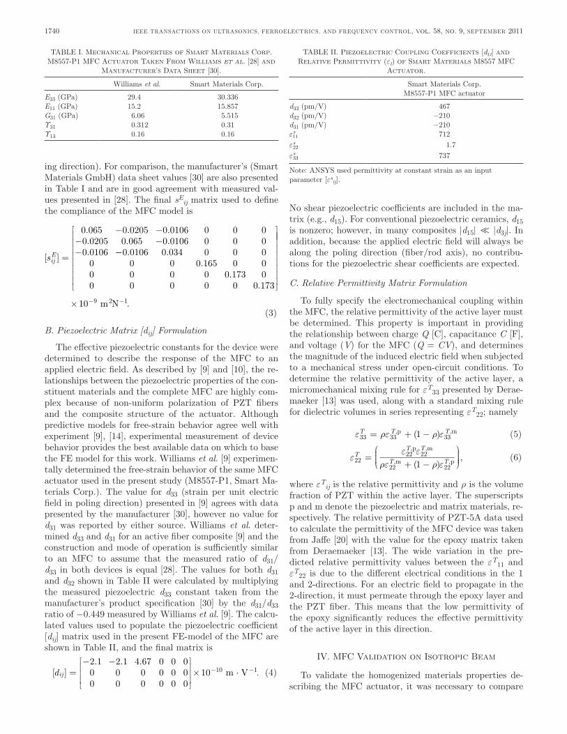
ing direction). For comparison, the manufacturer’s (smart materials GmbH) data sheet values [30] are also presented in Table I and are in good agreement with measured val-ues presented in [28]. The final sE
ij matrix used to define the compliance of the mFc model is
[ ]
. . .. . ..sijE =
− −− −−
0 065 0 0205 0 0106 0 0 00 0205 0 065 0 0106 0 0 00 0106 −−
0 0106 0 034 0 0 00 0 0 0 165 0 00 0 0 0 0 173 00 0 0 0 0 0 173
. ..
..
× − − m N10 9 2 1.
(3)
B. Piezoelectric Matrix [dij] Formulation
The effective piezoelectric constants for the device were determined to describe the response of the mFc to an applied electric field. as described by [9] and [10], the re-lationships between the piezoelectric properties of the con-stituent materials and the complete mFc are highly com-plex because of non-uniform polarization of pZT fibers and the composite structure of the actuator. although predictive models for free-strain behavior agree well with experiment [9], [14], experimental measurement of device behavior provides the best available data on which to base the FE model for this work. Williams et al. [9] experimen-tally determined the free-strain behavior of the same mFc actuator used in the present study (m8557-p1, smart ma-terials corp.). The value for d33 (strain per unit electric field in poling direction) presented in [9] agrees with data presented by the manufacturer [30], however no value for d31 was reported by either source. Williams et al. deter-mined d33 and d31 for an active fiber composite [9] and the construction and mode of operation is sufficiently similar to an mFc to assume that the measured ratio of d31/d33 in both devices is equal [28]. The values for both d31 and d32 shown in Table II were calculated by multiplying the measured piezoelectric d33 constant taken from the manufacturer’s product specification [30] by the d31/d33 ratio of −0.449 measured by Williams et al. [9]. The calcu-lated values used to populate the piezoelectric coefficient [dij] matrix used in the present FE-model of the mFc are shown in Table II, and the final matrix is
[ ]. . .
.dij =− −
× ⋅− −
2 1 2 1 4 67 0 0 00 0 0 0 0 00 0 0 0 0 0
10 10 1 m V (4)
no shear piezoelectric coefficients are included in the ma-trix (e.g., d15). For conventional piezoelectric ceramics, d15 is nonzero; however, in many composites |d15| ≪ |d3j|. In addition, because the applied electric field will always be along the poling direction (fiber/rod axis), no contribu-tions for the piezoelectric shear coefficients are expected.
C. Relative Permittivity Matrix Formulation
To fully specify the electromechanical coupling within the mFc, the relative permittivity of the active layer must be determined. This property is important in providing the relationship between charge Q [c], capacitance C [F], and voltage (V) for the mFc (Q = CV), and determines the magnitude of the induced electric field when subjected to a mechanical stress under open-circuit conditions. To determine the relative permittivity of the active layer, a micromechanical mixing rule for εT
33 presented by derae-maeker [13] was used, along with a standard mixing rule for dielectric volumes in series representing εT
22; namely
ε ρε ρ ε33 33 331T T T= + −, ,( )p m (5)
εε ε
ρε ρ ε2222 22
22 221T
T T
T T=+ −
, ,
, ,( ),
p m
m p (6)
where εTij is the relative permittivity and ρ is the volume
fraction of pZT within the active layer. The superscripts p and m denote the piezoelectric and matrix materials, re-spectively. The relative permittivity of pZT-5a data used to calculate the permittivity of the mFc device was taken from Jaffe [20] with the value for the epoxy matrix taken from deraemaeker [13]. The wide variation in the pre-dicted relative permittivity values between the εT
11 and εT
22 is due to the different electrical conditions in the 1 and 2-directions. For an electric field to propagate in the 2-direction, it must permeate through the epoxy layer and the pZT fiber. This means that the low permittivity of the epoxy significantly reduces the effective permittivity of the active layer in this direction.
IV. mFc Validation on Isotropic beam
To validate the homogenized materials properties de-scribing the mFc actuator, it was necessary to compare
TablE I. mechanical properties of smart materials corp. m8557-p1 mFc actuator Taken From Williams et al. [28] and
manufacturer’s data sheet [30].
Williams et al. smart materials corp.
E33 (Gpa) 29.4 30.336E11 (Gpa) 15.2 15.857G31 (Gpa) 6.06 5.515Υ31 0.312 0.31Υ13 0.16 0.16
TablE II. piezoelectric coupling coefficients [dij] and relative permittivity (εi) of smart materials m8557 mFc
actuator.
smart materials corp. m8557-p1 mFc actuator
d33 (pm/V) 467d32 (pm/V) −210d31 (pm/V) −210ε11s 712ε22s 1.7ε33s 737
note: ansys used permittivity at constant strain as an input parameter [εs
ij].

bowen et al.: modeling and characterization of piezoelectrically actuated composites 1741
FE model predictions of actuator deflection with experi-mental data. Two mFc actuators were bonded to a simple aluminum cantilever with one acting as an actuator and the other remaining passive to allow testing of the influ-ence of electrical boundary conditions.
A. Experimental Setup
Two mFc actuators (m-8557p1, smart materials corp.) were bonded to the front and back surfaces of an aluminum beam measuring 330 × 75 × 1.97 mm as shown in Fig. 2. The actuators and aluminum surfaces were cleaned using isopropyl alcohol and a thin coat of a two-part epoxy adhesive applied to both surfaces. The mFcs were then carefully located, while ensuring no air-bubbles were trapped during placement. With the mFcs in place, the assembly was placed under 200 n clamping force for 24 h to allow the epoxy to cure. both mFcs (labeled mFc-1 and mFc-2 in Fig. 2) were positioned so that the active area was located between z = 45 mm and z = 130 mm, with the poling direction of the pZT fibers (3-direction) parallel to the z-axis. The beam was clamped so that the 75 mm dimension (x-direction) was aligned vertically. This arrangement isolated beam deflection (Dy) from the influence of gravitational forces. a nippon las5010v laser displacement sensor (nippon automation co. ltd., Hamakita, Japan) with a resolution of 10 μm was used to measure cantilever deflection as a function of applied voltage. The active mFc (mFc-1) was driven from a signal generator attached to a pZd700 piezodriver (Trek Inc., medina, ny). closed-circuit boundary condi-tions were imposed on mFc-2 by connecting the positive and ground electrode terminals, whereas for open-circuit conditions, these terminals were insulated from one an-other. piezoelectric actuators are subject to slow creep under open loop control [31] because of domain motion. To standardize the piezoelectric creep effects [32], all mea-surements at each voltage were taken after a 60 s settling period. beam deflection at z = 120 mm as a function of mFc-1 drive voltage was measured from 0 to 400 V, taken at 80 V intervals. deflection measurements were carried out with mFc-2 under closed-circuit boundary conditions.
a datum measurement of beam position was taken before voltage application, and this value subtracted from the actuated beam position to calculate the deflection.
To measure the change in beam deflection caused by changing electric boundary conditions of mFc-2 beam deflection in response to 400 V mFc-1 drive voltage was measured at intervals of 30 mm between z = 120 mm and z = 300 mm. closed and open circuit measurements were taken sequentially at each z position. a separate datum measurement was taken for each measurement, and both mFc-1 and mFc-2 were electrically discharged between measurements.
B. FEM Model of MFC-Actuated Isotropic Beam
The aluminum cantilever was modeled using 20-node quadratic brick solId186 elements with isotropic me-chanical properties (young’s modulus 70.7 Gpa and pos-sion’s ratio 0.32). The two mFc actuators were repre-sented by 20-node quadratic brick solId226 elements. solId226 elements are coupled-field elements which solve the constitutive equations for an elastic piezoelectric solid. In addition to the improved solution accuracy of the 20-node quadratic elements in modeling highly curved struc-tures, when element types are combined within a single model, it is advisable to use 20-node elements throughout [33] to ensure that all nodes on adjacent elements are co-incident. attempting to merge nodes linked to a volume meshed using 8-node elements with 20-node elements con-nected to an adjacent volume can result in nodes losing connectivity with the model, introducing numerical er-rors and preventing model solution. once the model was appropriately meshed, the model consisted of a total of 4680 solId186 elements for the beam and 340 solId226 elements within the mFc volume. Element density was sufficient to accurately capture beam behavior, because further refinement of the mesh did not significantly affect the predicted beam deflection.
The mFc model volumes were positioned on the front and back surfaces of the cantilever as in Fig. 2 with all coincident nodes on the contact surfaces merged to ensure stress transfer between cantilever and actuator volumes. The clamped mechanical boundary condition was mod-eled by constraining all three translational degrees of free-dom (x, y, and z) for nodes lying in the range −30 mm < x < 0 mm on the y = 0 mm plane. nodes in the same range of x-coordinate on the y = 0.197 mm plane were constrained in the y-direction only. The FE model used to predict deflection of the experimental beam in response to mFc actuation is shown in Fig. 3. In creating the piezo-electric [dij] and permittivity [εij] matrices for the mFc actuator, it is assumed that electric field is constant along and aligned with the z-axis. To ensure a constant and well-aligned electric field, the voltage degree of freedom for nodes of equal z-coordinate was coupled to create planes of equal voltage at 5 mm intervals along the z-direction of the mFc volume. To model mFc behavior under closed-circuit boundary conditions (i.e., two electrodes of mFc-2
Fig. 2. Experimental setup with aluminum beam, driven actuator (mFc-1), and passive actuator (mFc-2) with dimensions shown in millimeters.

IEEE TransacTIons on UlTrasonIcs, FErroElEcTrIcs, and FrEqUEncy conTrol, vol. 58, no. 9, sEpTEmbEr 20111742
are electrically connected), the induced potential differ-ence as a result of a stress must be dissipated; however, it is inappropriate to constrain all voltage doFs within the mFc volume because it reduces solution accuracy [33]. Furthermore, simply altering the voltage constraints at the x = 35 mm and x = 120 mm faces would not suppress the induced field throughout the volume but only near the extremities. To suppress the induced field throughout the passive mFc volume (mFc-2 in Fig. 2) the piezoelectric coefficients (d33 and d31) for that volume were reduced by a factor 1 × 10⁹. This alteration of piezoelectric constants effectively modeled the suppressed induced field which characterizes closed-circuit electrical boundary conditions while maintaining solution accuracy.
C. Comparison of Model and Experimental Results
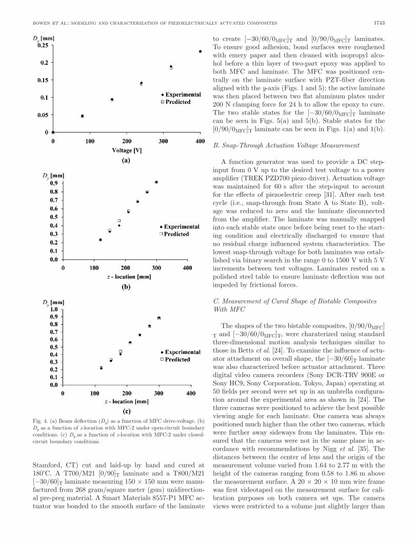
beam deflection as a function of mFc-1 drive-voltage is shown in Fig. 4(a) and clearly shows the linear trend pre-dicted by engineering beam theory and observed by other investigators [22], [34]. predicted FE values of cantilever deflection had excellent agreement with experimental val-ues to within 2%. It should be noted that for all values ex-cept the value for 160 V, the error was within measurement uncertainty of ±10 μm. Fig. 4(b) and Fig. 4(c) show beam deflection (Dy) as a function of distance from the clamped region of the cantilever with a drive voltage of 400 V ap-plied to mFc-1 and mFc-2 under open- and closed-circuit boundary conditions, respectively. FE-predictions of Dy were again accurate to within 2% compared with experi-mental values for both conditions. prediction of closed-circuit behavior showed excellent quantitative agreement with experiment, with predicted cantilever gradient (dy/dz) over the range 120 mm < z < 300 mm matching the
measured value of 3.8 μm·V−1 exactly. In addition, beam tip deflection was predicted to within 1% of the measured value of 0.905 mm. beam tip deflection decreased under open-circuit boundary conditions compared with closed-circuit values, with the predicted and observed values (0.873 mm and 0.880 mm, respectively) matching to with-in 1%. However, beam gradient under open-circuit bound-ary conditions was lower in the model by 2.6%, with FE prediction of 3.7 μm·V−1 compared with the experimental value of 3.6 μm·V−1. This difference in closed- and open-circuit conditions will not be captured by the thermal ap-proximations to piezoelectric actuation [16], [18], [22]. The small discrepancy between the measured and predicted beam deflection under open-circuit conditions indicates that the model generates a larger than expected voltage (via the V = Q/C relation) and electric field in mFc-2 because of the beam deflection. This suggests the relative permittivity used may be too low, leading to increased in-duced field and hence piezoelectric strain within the mFc-2, increasing the cantilever’s effective stiffness. neverthe-less, the excellent agreement for closed-circuit response indicates that both elastic and piezoelectric matrices are appropriately formulated. The next stage is to combine the mFc model with a bistable laminate to predict cured shape and snap-through voltage.
V. mFc-actuated bistable composite laminates
A. Bistable [0/90]T and [−30/60]T Composite Manufacture
Two cross-ply composite laminates were manufactured using carbon fiber-epoxy pre-preg material (Hexcel corp.,
Fig. 3. (a) Finite-element model used to predict beam deflection, showing coordinate system and symmetric boundary constraint, (b) mechanical constraint to model clamped-end condition of experimental setup, and (c) mesh density of both mFc volume and beam.
bowen et al.: modeling and characterization of piezoelectrically actuated composites 1743
stamford, cT) cut and laid-up by hand and cured at 180°c. a T700/m21 [0/90]T laminate and a T800/m21 [−30/60]T laminate measuring 150 × 150 mm were manu-factured from 268 gram/square meter (gsm) unidirection-al pre-preg material. a smart materials 8557-p1 mFc ac-tuator was bonded to the smooth surface of the laminate
to create [−30/60/0mFc]T and [0/90/0mFc]T laminates. To ensure good adhesion, bond surfaces were roughened with emery paper and then cleaned with isopropyl alco-hol before a thin layer of two-part epoxy was applied to both mFc and laminate. The mFc was positioned cen-trally on the laminate surface with pZT-fiber direction aligned with the y-axis (Figs. 1 and 5); the active laminate was then placed between two flat aluminum plates under 200 n clamping force for 24 h to allow the epoxy to cure. The two stable states for the [−30/60/0mFc]T laminate can be seen in Figs. 5(a) and 5(b). stable states for the [0/90/0mFc]T laminate can be seen in Figs. 1(a) and 1(b).
B. Snap-Through Actuation Voltage Measurement
a function generator was used to provide a dc step-input from 0 V up to the desired test voltage to a power amplifier (TrEK pZd700 piezo driver). actuation voltage was maintained for 60 s after the step-input to account for the effects of piezoelectric creep [31]. after each test cycle (i.e., snap-through from state a to state b), volt-age was reduced to zero and the laminate disconnected from the amplifier. The laminate was manually snapped into each stable state once before being reset to the start-ing condition and electrically discharged to ensure that no residual charge influenced system characteristics. The lowest snap-through voltage for both laminates was estab-lished via binary search in the range 0 to 1500 V with 5 V increments between test voltages. laminates rested on a polished steel table to ensure laminate deflection was not impeded by frictional forces.
C. Measurement of Cured Shape of Bistable Composites With MFC
The shapes of the two bistable composites, [0/90/0mFc]T and [−30/60/0mFc]T, were charaterized using standard three-dimensional motion analysis techniques similar to those in betts et al. [24]. To examine the influence of actu-ator attachment on overall shape, the [−30/60]T laminate was also characterized before actuator attachment. Three digital video camera recorders (sony dcr-TrV 900E or sony Hc9, sony corporation, Tokyo, Japan) operating at 50 fields per second were set up in an umbrella configura-tion around the experimental area as shown in [24]. The three cameras were positioned to achieve the best possible viewing angle for each laminate. one camera was always positioned much higher than the other two cameras, which were further away sideways from the laminates. This en-sured that the cameras were not in the same plane in ac-cordance with recommendations by nigg et al. [35]. The distances between the center of lens and the origin of the measurement volume varied from 1.64 to 2.77 m with the height of the cameras ranging from 0.58 to 1.86 m above the measurement surface. a 20 × 20 × 10 mm wire frame was first videotaped on the measurement surface for cali-bration purposes on both camera set ups. The camera views were restricted to a volume just slightly larger than
Fig. 4. (a) beam deflection (Dy) as a function of mFc drive-voltage. (b) Dy as a function of z-location with mFc-2 under open-circuit boundary conditions. (c) Dy as a function of z-location with mFc-2 under closed-circuit boundary conditions.

IEEE TransacTIons on UlTrasonIcs, FErroElEcTrIcs, and FrEqUEncy conTrol, vol. 58, no. 9, sEpTEmbEr 20111744
the calibration frame. after removing the frame, the lami-nate was positioned within this measurement volume and videotaped simultaneously with all three cameras.
To map arbitrary coordinates on the surface of the laminates to later create the shape of the laminate, mark-ers were attached on one surface of the laminate. The [−30/60]T and [−30/60/0mFc]T laminates had 145 round color labels of 8 mm diameter attached to it, as shown in Fig. 5. The size of the markers were reduced for the [0/90/0mFc]T laminate, allowing 279 markers to be put on the surface. The four corner points of each laminate were also used.
The actual mapping of the surface coordinates was car-ried out using peakmotus motion analysis system (v. 8.5, Vicon, centennial, co) after transferring the calibration and laminate video clips onto the computer. First, the eight corners of the calibration wire frame were manually digitized from each camera view (and for each camera set up). Then, the center of each surface marker and the four corners of the each laminate were manually digitized from all three camera views. The digitized area on the com-puter screen was 1440 × 1152 pixels. The digitized pixel information from each camera view was combined with the calibration information to transform these to carte-sian coordinates of the laminate surfaces using the direct linear transformation method [36]. The largest directional coordinate rms error of the different set ups between the known eight calibration coordinates and the respec-tive digitized point was 0.3 mm. The interpolated surface was then constructed from the raw coordinates using the spline-based interpolation method [37] for comparison with FE predictions.
D. Development of MFC-Actuated Bistable Composite Model
a non-linear large deflection FE analysis was conduct-ed to predict both cured shape and snap-through voltage. model convergence was controlled using the line search convergence control method to improve numerical stabil-ity [33], [38]. Formulation of this mFc-bistable composite model was far more complex than the simple isotropic alu-minum cantilever beam, because it is necessary to capture:
1) The bistable states of the asymmetrical composite and the corresponding laminate curvature as a result of cooling the asymmetrical composite from the cure temperature,
2) The influence of attaching the mFc actuator to the laminate at room temperature on the curvature of the bistable laminate–mFc combination,
3) The prediction of a snap-through event as a result of the application of a voltage to the mFc.
The [−30/60/0mFc]T laminate was modeled using 20-node quadratic solId186 layered brick elements. The laminate was modeled as three volumes shown in Fig 6. a central strip measuring 57 × 150 mm was located underneath the mFc volume (point 1 in Fig. 6) and was meshed with 1360 elements; whereas the two remaining volumes, each measuring 46.5 × 150 mm (points 2 and 3 in Fig. 6) were meshed with 816 elements each to create the mesh shown in Fig. 6(a). maximum element aspect ratio within the laminate was 9.14. all coincident nodes within the lami-nate volume were then merged to ensure stress transfer during model solution. To make use of symmetry in the [0/90/0mFc]T laminate, a symmetric boundary condition was imposed along the x = 0 mm plane. The mean ply-thicknesses for the laminates with ply angles of [θ/θ + 90]T were determined by optical microscopy and used to ap-proximate the laminates’ individual ply thicknesses. Table III shows the mean and standard deviation of ply thick-ness and total laminate thickness for a range of manufac-tured laminates with ply angles of [θ/θ + 90]T. materials properties for the laminate were determined by batch test-ing undertaken by airbus UK [39] for both T700/m21 and T800/m21 pre-preg material, and are shown in Table IV.
a volume measuring 85 × 57 × 0.3 mm was defined and ascribed the homogenized mFc materials properties (section III) to represent the active area of the smart materials mFc8557p1 actuator. The actuator volume was located centrally on the upper surface of the lami-nate with mFc-fiber orientation aligned with the y-axis as indicated in Fig. 6(b). This volume was meshed with 1200 solId226 elements with a maximum element aspect ratio of 9.33. With all volumes meshed, coincident nodes on adjacent surfaces of laminate and mFc were merged
Fig. 5. (a) cured shape of [−30/60/0mFc]T laminate in state a with global coordinate system and (b) state b showing local material coordinate system for uppermost 60° ply. circular markers are attached for coordinate mapping of the surface.

bowen et al.: modeling and characterization of piezoelectrically actuated composites 1745
along with coincident areas to ensure stress transfer be-tween the laminate and mFc volumes. because of the selection of higher-order solid elements, it is possible to accurately model bending deformation without multiple elements through the thickness [40], and hence a single-element thickness was used. With all volumes meshed and the mFc and laminate volumes merged, the laminate models were mechanically constrained from translation in all three orthogonal directions at the origin of the global coordinate system, shown in Fig. 7. additionally the node at the point (0, 0, 0.515) was constrained from in-plane translation to ensure the laminate did not rotate about either the x or y-axis (Fig. 7). because of actuator orien-tation in the experimental sample, the FE model must converge to stable deformation state b before applica-
tion of mFc drive-voltage. To force the FE solution to converge to state b, temporary displacement constraints were applied at locations of minimum state b deflection as indicated in Fig. 7(b).
E. Active Laminate Model—Model Solution
With the model mechanically constrained, the cool-down of the bistable composite laminate from the autoclave tem-perature (180°c) and attachment of the mFc actuator at room temperature was modeled in a four-step process:
1) application of a temperature change of −160K to composite elements to ensure that the laminate con-verges to state b.
Fig. 6. (a) meshed FE model of [−30/60/0mFc]T laminate showing three laminate volumes (1, 2, and 3) and centrally located mFc volume, (b) overall mesh density and detail of coincident nodes near corner of mFc volume and global coordinate system.
TablE III. mean and standard deviation (σ) of ply and Total laminate Thickness for [θ/θ+90]T laminates made From 268gsm m21/T800.
Idealized measured
Thickness (mm) Thickness (mm) σ
θ˚ ply 0.25 0.255 0.013θ +90° ply 0.25 0.233 0.018resin layer 0 0.027 0.021Total 0.5 0.515 0.045
TablE IV. Elastic properties of 268gsm-1 T800/m21 material and T700/m21.
property [unit] T700/m21 T800/m21
E1 [Gpa] 148 172E2 & E3 [Gpa] 7.8 8.9G12 & G23 [Gpa] 3.8 4.2G23* [Gpa] 0.02 0.02ν12 & ν13 0.35 0.35ν23* 0.01 0.01α1 [1 × 10⁻⁷ °c−1] −0.9 −0.9α2 & α3 [1 × 10⁻⁵ °c−1] 3 3Er [Gpa] 1.5 1.5νr 0.4 0.4αr [1 × 10⁻⁵ °c−1] 9 9density [kg·m−3] 1072 1072
*Indicates values calculated using stress-strain relations described in [29].

IEEE TransacTIons on UlTrasonIcs, FErroElEcTrIcs, and FrEqUEncy conTrol, vol. 58, no. 9, sEpTEmbEr 20111746
2) application of an offset voltage to compensate for thermal stress imposed on the mFc volume.
3) removal of temporary displacement constraints [shown in Fig. 7(b)].
4) application of mFc drive-voltage until snap-through of the structure into state a.
Fig. 8(a) shows the laminate and mFc model at the cure temperature of 180°c which is initially flat. Fig. 8(b) shows the highly curved structure at a temperature of 20°c with the temporary displacement constraints still in place. Fig. 8(b) represents stage 1 of the solution process. Fig. 8(c) shows the laminate model after application of the offset
voltage (V0) and removal of the temporary displacement constraints; this represents stages 2 and 3 of the solution process. during application of mFc drive voltage (stage 4 in the solution process), the laminate flattened as mFc drive-voltage and the resulting actuation strain increased before undergoing the sudden transition into deformation state a (snap-through).
To model the cool down from elevated curing tempera-ture of the composite laminate, a temperature difference was applied to the composite elements. The temperature constraint was applied only to composite (solId186) ele-ments, whereas the coupled-field (solId226) elements of the mFc were not subjected to the imposed temperature
Fig. 7. (a) meshed FE model, showing mechanical constraint at origin of global coordinate system and (b) temporary mechanical constraint used to force model convergence to deformation state b.
Fig. 8. (a) Finite-element prediction of cured shape for [−30/60/0mFc]T laminate at cure temperature of 180°c, (b) room temperature of 20°c, and (c) in stable deformation state b with offset voltage (V0) applied.
bowen et al.: modeling and characterization of piezoelectrically actuated composites 1747
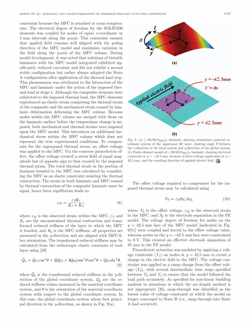
constraint because the mFc is attached at room tempera-ture. The electrical degree of freedom for the solId226 elements was coupled for nodes of equal z-coordinate at 5 mm intervals along the y-axis. This constraint ensures that applied field remains well aligned with the poling direction of the mFc model and minimizes variation in the field along the y-axis of the mFc volume. during model development, it was noted that solutions of bistable laminates with the mFc model integrated exhibited sig-nificantly reduced curvature and did not exhibit a second stable configuration but rather always adopted the state a configuration after application of the thermal load step. This phenomenon was attributed to the interaction of the mFc and laminate under the action of the imposed ther-mal load at stage 1. although the composite elements were subjected to the imposed thermal load, the mFc elements experienced an elastic strain comprising the thermal strain of the composite and the mechanical strain caused by lam-inate deformation deforming the mFc volume. because nodes within the mFc volume are merged with those on the laminate surface before the temperature change is im-posed, both mechanical and thermal strains were imposed upon the mFc model. This introduces an additional me-chanical stress within the mFc volume which does not represent the true experimental conditions. To compen-sate for the superposed thermal stress, an offset voltage was applied to the mFc. Via the converse piezoelectric ef-fect, the offset voltage created a stress field of equal mag-nitude but of opposite sign to that created by the imposed thermal strain. The total thermal strain in the portion of laminate bonded to the mFc was calculated by consider-ing the mFc as an elastic constraint resisting the thermal contraction. The strain in both laminate and mFc caused by thermal contraction of the composite laminate must be equal, hence force equilibrium leads to:
εε
MT=+K
K K1
1 2, (8)
where εm is the observed strain within the mFc, εT and K1 are the unconstrained thermal contraction and trans-formed reduced stiffness of the layer to which the mFc is bonded, and K2 is the mFc stiffness; all properties are measured in the y-direction and are aligned with mFc-fi-ber orientation. The transformed reduced stiffness may be calculated from the orthotropic elastic constants of each layer using [29]
Q Q Q Q Qy = + + +114
12 662 2
2242 2cos ( )sin cos sin ,θ θ θ θ
(9)
where Qy is the transformed reduced stiffness in the y-di-rection of the global coordinate system, Qij are the re-duced stiffness values measured in the material coordinate system, and θ is the orientation of the material coordinate system with respect to the global coordinate system. In this case, the global coordinate system whose first princi-pal direction is the y-direction, as shown in Fig. 9(a).
The offset voltage required to compensate for the im-posed thermal strain may be calculated using
V S d0 33= εM E/ , (10)
where V0 is the offset voltage, εm is the observed strain in the mFc, and SE is the electrode separation in the FE model. The voltage degree of freedom for nodes on the y = 42.5 mm face of the mFc model [indicated in Fig. 9(b)] were coupled and forced to the offset voltage value, whereas nodes on the y = −42.5 mm face were constrained to 0 V. This created an effective electrode separation of 85 mm in the FE model.
piezoelectric actuation was modeled by applying a volt-age constraint (Vc) on nodes at y = 42.5 mm to create a change in the electric field in the mFc. The voltage con-straint was applied as a ramp change from the offset volt-age (V0), with several intermediate time steps specified between V0 and Vc to ensure that the model followed the load path accurately. as specified for non-linear buckling analysis in situations in which the arc-length method is not appropriate [26], snap-through was identified as the lowest value of voltage constraint at which the model no longer converged to state b (i.e., snap-through into state a had occurred).
Fig. 9. (a) [−30/60/0mFc]T laminate, showing orientation material co-ordinate system of the uppermost 60° layer, showing angle θ between the 1-direction of the local system and y-direction of the global system. (b) Finite-element model of [−30/60/0mFc]T laminate, showing electrical constraint at y = −42.5 mm, location of drive-voltage application at y = 42.5 mm, and the resulting direction of applied electric field.

IEEE TransacTIons on UlTrasonIcs, FErroElEcTrIcs, and FrEqUEncy conTrol, vol. 58, no. 9, sEpTEmbEr 20111748
F. Laminate Shape (Model and Experimental)
The predicted shape of a [−30/60/0mFc]T active lami-nate in state b is shown in Fig. 10(a) with deviations from simple cylindrical curvature seen at points a and c. The meshed regions in Fig. 10(a) are the FE predictions and the solid-colored sections are the experimental mea-surement. overall, the agreement between the two is very good. The laminate adopts a saddle-shape after mFc ad-dition with a significantly flattened section directly under-neath the mFc (point b). This reduction in curvature un-derneath the mFc indicates that the bending stiffness of the actuator has a significant effect on the cured shape of the laminate. When comparing maximum deflections with respect to the laminate geometric center (Dmax) before and after mFc-bonding, the influence of mFc addition is clear with measured deflections of 38.2 mm for the lami-nate (without mFc) reduced to 22.5 mm after mFc ad-dition. maximum deflection for the [−30/60/0mFc]T lami-
nate after mFc addition was predicted to be 25.20 mm for state b, 12.1% higher than the measured maximum deflection of 22.48 mm.
Fig. 10(b) shows an interpolated surface plot of ex-perimental measurement of laminate deflection for the [0/90/0mFc]T laminate in state b with the FE predic-tion overlaid as a mesh. The results again show close agreement between model and experiment. maximum deflection for the [0/90/0mFc]T laminate after mFc ad-dition was predicted to be 10.73 mm for state b, 16% lower than experimentally measured maximum deflection of 12.77 mm. Variations in laminate composition and ply orientation commonly seen during hand manufacture can create variations in observed laminate deflection [24]. be-cause of the high sensitivity of predicted deflection to lam-inate composition, it is likely that small deviations from the mean mFc thickness and pZT volume fraction would also introduce errors. The combined effect of these un-known variations in laminate and mFc composition could account for the observed errors in predictions of laminate deflection. despite limitations in quantitative prediction, the model captures the cured shape and local reversals of curvature very well.
G. Snap-Through (Model and Experiment)
Finite-element prediction of snap-through voltage was achieved for both laminates, with non-linear buckling analyses predicting behavior before snap-through. For the [0/90/0mFc]T laminate, the model predicts snap-through at 645 V, whereas experimental observation showed that a drive voltage of 670 V induced snap-through. In the case of the [−30/60/0mFc]T laminate, the predicted and observed snap-through voltages were 677 V and 700 V, respectively. The predicted snap-through voltages are in excellent agreement with the measured values with errors of less than 4.5% in both cases compared with experimen-tal data. delayed snap-through was observed at voltages immediately below monotonic snap-through voltage when drive-voltage was applied for a prolonged time period. This was caused by creep of the mFc actuators [31] and could be compensated for in industrial applications by us-ing time-varying input signals [32] and closed-loop con-trol. because of the discontinuity of the voltage-deflection curve associated with snap-through, the newton-raphson solution procedure was not able to predict laminate re-sponse throughout the entire load cycle even with line search convergence control enabled.
To fully track voltage-deflection behavior of bistable lami-nates under mFc actuation, implementation of non-linear stabilization or the arc-length solution methods is necessary. However, neither non-linear stabilization nor the arc-length solution methods are currently implementable with sol-Id226 elements. Therefore, the presented model represents the most appropriate formulation within the ansys V11.0 FE software and has significantly extended modeling capa-bility and accuracy of coupled-field FE models in the predic-tion of actuation behavior of bistable composites.
Fig. 10. (a) Interpolated surface plot of 149 measured surface coordinates showing the [−30/60/0mFc]T laminate in state b with the FE-predicted surface overlaid as a mesh. (b) Interpolated surface plot based on 283 measured surface coordinates showing the [0/90/0mFc]T laminate in state b with FE-predicted surface overlaid as a mesh (laminate shown inverted for clarity of presentation).

bowen et al.: modeling and characterization of piezoelectrically actuated composites 1749
VI. conclusions
a homogenized FE model of a commercially available mFc actuator was developed and validated to allow pre-diction of actuator performance under combined electri-cal and stress fields. Three-dimensional piezoelectric and stiffness matrices for the mFc were calculated using ex-perimentally determined orthotropic constants to create a homogenized material model of the mFc actuator. This data was validated by comparing FE predictions to ex-perimental measurements of tip deflection of an isotropic beam with mFc actuators bonded to both top and bot-tom surfaces. predicted values of deflection agreed with experimental data to within 2.5% over this range. With an mFc under closed-circuit boundary conditions, both de-flection and gradient of the beam were predicted to with-in 1% of experimental measurement. Under open-circuit conditions, the developed electrical field within the mFc caused a reduction in beam gradient that remained within 1% of experimental values.
The mFc model was integrated with the model for bi-stable laminates to predict cured shape and snap-through behavior of two cross-ply bistable laminates. challenges associated with integration of coupled-field elements with the composite structure have been addressed through ap-plication of an offset voltage to compensate for undesired thermal stresses within the mFc volume. prediction of cured shape after mFc addition is in good agreement with experimental measurement, with maximum error between prediction and measured values of 12 to 16%. The change in cured shape caused by mFc addition and localized variation in curvature were predicted, and quantitative prediction of laminate deflection agrees with experiment sufficiently well to aid prototype design. snap-through voltage for both [0/90/0mFc]T and [−30/60/0mFc]T lami-nates were predicted to within 4.5% of experimental mea-surements, which is a significant improvement upon previ-ously unvalidated attempts at predicting snap-through. by including correctly formulated homogenized mFc properties and appropriate electrical constraints, the pre-sented model improves and extends the applicability of FE techniques available for mechanism design of morph-ing structures based on bistable composites.
acknowledgments
We wish to acknowledge the financial support of Great Western research (GWr) and airbus.
references
[1] s. barbarino, s. ameduri, l. lecce, and a. concilio, “Wing shape control through an sma-based device,” J. Intell. Mater. Syst. Struct., vol. 20, no. 3, pp. 283–296, 2009.
[2] a. natarajan, r. K. Kapania, and d. J. Inman, “aeroelastic opti-mization of adaptive bumps for yaw control,” J. Aircr., vol. 4, no. 1, pp. 175–185, 2004.
[3] m. r. schultz, “a concept for airfoil-like active bistable twisting structures,” J. Intell. Mater. Syst. Struct., vol. 19, no. 2, pp. 157–169, 2008.
[4] c. r. bowen, r. butler, r. Jervis, H. a. Kim, and a. I. T. salo, “morphing and shape control using asymmetrical composites,” J. Intell. Mater. Syst. Struct., vol. 18, no. 1, pp. 89–98, 2007.
[5] m. W. Hyer, “calculations of the room-temperature shapes of asym-metric laminates,” J. Compos. Mater., vol. 15, pp. 296–310, Jul. 1981.
[6] p. F. Giddings, c. r. bowen, a. I. T. salo, and H. a. Kim, “bistable composite laminates: Effects of laminate composition on cured shape and response to thermal load,” Compos. Struct., vol. 92, no. 9, pp. 2220–2225, 2010.
[7] c. r. bowen, r. stevens, l. J. nelson, a. c. dent, G. dolman, b. su, T. W. button, m. G. cain, and m. stewart, “manufacture and characterization of high activity piezoelectric fibres,” Smart Mater. Struct., vol. 15, no. 2, pp. 295–301, 2006.
[8] b. Jaffe and W. r. cook, Piezoelectric Ceramics. london, UK: aca-demic, 1971.
[9] b. r. Williams, d. J. Inman, and W. K. Wilkie, “nonlinear response of the macro fiber composite actuator to monotonically increasing excitation voltage,” J. Intell. Mater. Syst. Struct., vol. 17, no. 7, pp. 601–608, 2006.
[10] r. paradies and b. schlapfer, “Finite element modeling of piezoelec-tric elements with complex electrode configuration,” Smart Mater. Struct., vol. 18, no. 2, art. no. 025015, 2009.
[11] c. r. bowen, a. bowles, s. drake, n. Johnson, and s. mahon, “Fab-rication and finite element modelling of interdigitated electrodes,” Ferroelectrics, vol. 228, no. 1, pp. 257–269, 1999.
[12] J. m. lloyd, r. b. Williams, d. J. Inman, and W. K. Wilkie, “an analytical model of the mechanical properties of the single crys-tal macro-fiber composite actuator.” Proc. SPIE, vol. 6, no. 2, pp. 37–46, 2004.
[13] a. deraemaeker, H. nasser, a. benjeddou, and a. preumont, “mix-ing rules for the piezoelectric properties of macro fiber composites,” J. Intell. Mater. Syst. Struct., vol. 20, no. 12, pp. 1475–1482, 2009.
[14] c. r. bowen, l. J. nelson, r. stevens, m. G. cain, and m. stewart, “optimisation of interdigitated electrodes for piezoelectric actuators and active fibre composites,” J. Electroceram., vol. 16, no. 4, pp. 263–269, 2006.
[15] s. c. choi, J. s. park, and J. H. Kim, “Vibration control of pre-twisted rotating composite thin-walled beams with piezoelectric fi-ber composites,” J. Sound Vibrat., vol. 300, no. 1-2, pp. 176–196, 2007.
[16] p. portela, p. camanho, p. Weaver, and I. bond, “analysis of mor-phing, multi stable structures actuated by piezoelectric patches,” Comput. Struc., vol. 86, no. 3-5, pp. 347–356, 2008.
[17] p. binette, m.l. dano, and G. Gendron, “active shape control of composite structures under thermal loading,” Smart Mater. Struct., vol. 18, no. 2, art. no. 025007, 2009.
[18] m. r. schultz and m. W. Hyer, “snap-through of asymmetric cross-ply laminates using piezoceramic actuators,” J. Intell. Mater. Syst. Struct., vol. 14, pp. 795–814, dec. 2003.
[19] T. Ikeda, Fundamentals of Piezoelectricity. oxford, UK: oxford Uni-versity press, 1990.
[20] H. Jaffe and d. a. berlincourt, “piezoelectric transducer materials,” Proc. IEEE, vol. 53, no. 10, pp. 1372–1386, 1965.
[21] m. l. dano, m. Gakwaya, and b. Julliere, “compensation of ther-mally induced distortion in composite structures using macro-fiber composites,” J. Intell. Mater. Syst. Struct., vol. 19, no. 2, pp. 225–233, 2008.
[22] l. b. ren, “a theoretical study on shape control of arbitrary lay-up laminates using piezoelectric actuators,” Compos. Struct., vol. 83, no. 1, pp. 110–118, 2008.
[23] J. Etches, K. potter, p. Weaver, and I. bond, “Environmental ef-fects on thermally induced multistability in asymmetric composite laminates,” Compos., Part A Appl. Sci. Manuf., vol. 40, no. 8, pp. 1240–1247, 2009.
[24] d. n. betts, a. I. T. salo, c. r. bowen, and H. a. Kim, “char-acterisation and modelling of the cured shapes of arbitrary layup bistable composite laminates,” Compos. Struct., vol. 92, no. 7, pp. 1694–1700, 2010.
[25] m. Gude and W. Hufenbach, “design of novel morphing structures based on bistable composites with piezoceramic actuators,” Mech. Compos. Mater., vol. 42, no. 4, pp. 339–346, 2006.
[26] ansys Inc., “structures with geometric non-linearities. paper 3,” ansys Theory reference V11.0, 2007.
IEEE TransacTIons on UlTrasonIcs, FErroElEcTrIcs, and FrEqUEncy conTrol, vol. 58, no. 9, sEpTEmbEr 20111750
[27] m. Gude, W. Hufenbach, and c. Kirvel, “piezoelectrically driven morphing structures based on bistable unsymmetric laminates,” Compos. Struct., vol. 93, no. 2, pp. 377–382, 2011.
[28] r. b. Williams, d. J. Inman, m. r. schultz, m. W. Hyer, and W. K. Wilkie, “nonlinear tensile and shear behavior of macro fiber com-posite actuators,” J. Compos. Mater., vol. 38, no. 10, pp. 855–869, 2004.
[29] m. W. Hyer, Stress Analysis of Fibre Reinforced Composite Materi-als. boston, ma: Wcb/mcGraw-Hill, 1998.
[30] smart material corp. (2010, dec 15). macro fiber composite—mFc. [online]. available: http://www.smart-material.com/mFc-product-main.html
[31] H. Jung and d. G. Gweon, “creep characteristics of piezoelectric actuators,” Rev. Sci. Instrum., vol. 71, no. 4, pp. 1896–1900, 2000.
[32] H. Jung, J. y. shim, and d. G. Gweon, “Tracking control of piezo-electric actuators,” Nanotechnology, vol. 12, no. 1, pp. 14–20, 2001.
[33] ansys Inc., “coupled field analysis guide,” ansys user help refer-ence system V11.0, 2007.
[34] p. Giddings, c. r. bowen, H. Kim, and r. butler, “characterisa-tion of actuation properties of piezoelectric bi-stable carbon-fibre laminates,” Compos. A, vol. 39, no. 4, pp. 697–703, 2008.
[35] b. m. nigg, G. K. cole, and I. c. Wright, “optical methods,” in Biomechanics of the Musculo-Skeletal System, b. m. nigg and W. Herzog, Eds., chichester, UK: Wiley, 2007, pp. 362–391.
[36] y. I. abdel-aziz and H. m. Karara, “direct linear transformation from comparator coordinates into object space coordinates in close-range photogrammetry,” in Proc. ASP/IU Symp. Close-Range Pho-togrammetry, 1971, pp. 1–118.
[37] d. T. sandwell, “biharmonic spline interpolation of GEos-3 and sEasaT altimeter data,” Geophys. Res. Lett., vol. 14, no. 1, pp. 139–142, 1987.
[38] ansys Inc., “newton-raphson procedure. paper 15,” ansys Theo-ry reference V11.0, 2007.
[39] m. desailloud, “modulus harmonisation of Hs & Im tape composite materials,” airbus section 530, rep. no. Esac_rp0306315, 2004.
[40] ansys Inc., “structures with geometric non-linearities. paper 3,” ansys Theory reference V11.0, 2007.
Christopher Rhys Bowen has a b.sc. degree in materials science from the University of bath (1986–1990) and a d.phil. in ceramics from the University of oxford (1990–1993). post-doctoral work has been undertaken at Tecnische Univer-sität Harburg-Hamburg and the University of leeds (1994–1996). He was senior scientist at the defence Evaluation and research agency (dEra) from 1996 to 1998. He joined the University of bath as a lecturer in 1998. His research interests include dielectrics, piezoelectric materials, piezo-
electric composites, and smart systems. He enjoys playing with his daughter, rhiannon bowen.
Peter F. Giddings was born in norfolk, Eng-land in 1982. He began investigating novel multi-stable composite structures as part of an Epsrc-funded undergraduate research program whilst completing his m.Eng. degree in 2007 at the Uni-versity of bath, England. The work he started as an undergraduate formed the basis for a ph.d. investigation into the use of piezoelectrically actu-ated bistable structures for morphing structures within aerospace applications that was co-funded by the Great Western research (GWr and airbus
UK ltd.) grant which was awarded in 2010 by the department of me-chanical Engineering at the University of bath. since 2008, dr. Giddings has developed successful businesses in biomechanical assessment and coaching of endurance cyclists and technical communication for special-ist consumer publications and business-to-business media from his home in Toulouse, France.
Aki I. T. Salo was born in mikkeli, Finland, in 1964. He received an m.sc. degree in sport sci-ences from the University of Jyväskylä, Finland, in 1991 and a ph.d. degree from the University of Exeter, England, in 1999. He worked as a research assistant in the research Institute for olympic sports, Jyväskylä, Finland, from 1991 to 1994, af-ter which he moved to England. after taking a few research assistant posts in England, since 1998, he has worked as a lecturer/senior lecturer in sport biomechanics at the University of bath, England.
While analyzing athletes’ technique is dr salo’s primary work, he has developed expertise in using human motion analysis systems innova-tively to analyze the shapes and movement of bistable composites and active structures with colleagues at the department of mechanical Engi-neering in bath. His skills offer a unique capability for three-dimensional shape characterization and provide significant experimental data in com-parison to mathematical modeling of these structures.
Hyunsun Alicia Kim has b.Eng. and ph.d. de-grees (1993–2000) in aeronautical engineering from the University of sydney, australia, and car-ried out the post-doctoral research at the Univer-sity of Warwick, UK, and Virginia Tech. she joined the University of bath in 2001 and is cur-rently a senior lecturer in aerospace structures. she is an affiliate at the los alamos national laboratory. Her research interests are in the de-velopment and application of computational methods for modeling and optimization. more
specifically, they are in the fields of structural and topology optimization, optimization of actuated composites, material modeling of nonlinearity and hysteresis, bone remodeling, and surrogate modeling.