model ymc magnetic bearing centrifugal liquid chillers
TRANSCRIPT
form 160.84-EG1 (516)
modEl YmC2 maGnEtiC BEarinG CEntrifuGal liquid ChillErs
165-1000 tons 580-3520 kW
50 & 60 hzhfC-134a
&165-840 tons580-2950 kW
50hzhfC-134a
JOHNSON CONTROLS
FORM 160.84-EG1 (516)
2
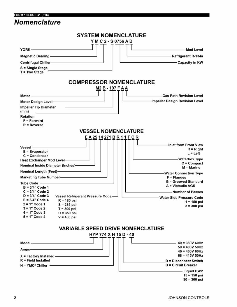
Nomenclature
VESSEL NOMENCLATURE
Inlet from Front ViewR = RightL = Left
Waterbox TypeC = CompactM = Marine
Water Side Pressure Code1 = 150 psi3 = 300 psi
Water Connection TypeF = Flanges
G = Grooved StandardA = Victaulic AGS
Number of Passes
Vessel E = Evaporator C = Condenser
Vessel Refrigerant Pressure Code R = 180 psi S = 235 psi T = 300 psi U = 350 psi V = 400 psi
Tube Code B = 3/4" Code 1 C = 3/4" Code 2 D = 3/4" Code 3 E = 3/4" Code 4 2 = 1" Code 1 3 = 1" Code 2 4 = 1" Code 3 5 = 1" Code 4
Heat Exchanger Mod LevelNominal Inside Diameter (Inches)Nominal Length (Feet)Marketing Tube Number
E A 25 14 271 B R 1 1 F C R
COMPRESSOR NOMENCLATURE
Gas Path Revision LevelImpeller Design Revision Level
MotorMotor Design LevelImpeller Tip Diameter (mm)Rotation F = Forward R = Reverse
M2 B - 197 F A A
SySTEM NOMENCLATURE
yORK
Centrifugal Chiller
Magnetic Bearing
Mod Level
S = Single StageT = Two Stage
Capacity in KW
Refrigerant R-134a
y M C 2 - S 0756 A B
Liquid DWP15 = 150 psi30 = 300 psi
40 = 380V 60Hz 50 = 400V 50Hz46 = 460V 60Hz68 = 415V 50Hz
D = Disconnect SwitchB = Circuit Breaker
X = Factory Installed R = Field Installed
VARIABLE SPEED DRIVE NOMENCLATURE
Model
H = yMC2 Chiller
Amps
HyP 774 X H 15 D - 40
FORM 160.84-EG1 (516)
JOHNSON CONTROLS 3
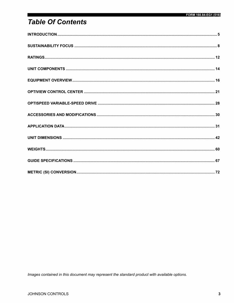
Table Of ContentsINTRODUCTION ...................................................................................................................................................... 5
SUSTAINABILITy FOCUS ...................................................................................................................................... 8
RATINGS ................................................................................................................................................................ 12
UNIT COMPONENTS ............................................................................................................................................ 14
EqUIPMENT OVERVIEW ...................................................................................................................................... 16
OPTIVIEW CONTROL CENTER ........................................................................................................................... 21
OPTISPEED VARIABLE-SPEED DRIVE .............................................................................................................. 28
ACCESSORIES AND MODIFICATIONS ............................................................................................................... 30
APPLICATION DATA ............................................................................................................................................. 31
UNIT DIMENSIONS ............................................................................................................................................... 42
WEIGHTS ............................................................................................................................................................... 60
GUIDE SPECIFICATIONS ..................................................................................................................................... 67
METRIC (SI) CONVERSION .................................................................................................................................. 72
Images contained in this document may represent the standard product with available options.

JOHNSON CONTROLS
FORM 160.84-EG1 (516)
4
This Page inTenTionally lefT Blank.
FORM 160.84-EG1 (516)
JOHNSON CONTROLS 5
the YorK® YmC² chiller offers a full package of features for total owner satisfaction. Key benefits include efficiency, sustainability, quiet operation, and reliability.
EFFICIENCy
actual chiller efficiency cannot be determined by analyzing the theoretical efficiency of any one chiller component. it requires a specific combination of heat exchanger, com-pressor, and motor performance to achieve the lowest system kW/ton. YmC² technology matches chiller system components to provide maximum chiller efficiency under actual – not just theoretical – operating conditions. the YmC² chiller lowers energy costs with up to 10% better efficiency than existing designs at both full and part-load conditions.
Johnson Controls pioneered the term “real-World Energy” to illustrate the energy-saving potential of focusing on chiller performance during off-design conditions. off-design condi-tions are not only seen at part-load, but at full-load operation as well, by taking advantage of reduced entering condenser water temperatures (ECWts). this is where chillers oper-ate 99% of the time, and where operating costs add up. YmC² chillers are the only chillers designed to operate on a continuous basis with cold ECWt and full condenser flow at all load points, taking full advantage of real-World conditions. this type of operation benefits the cooling tower as well by reducing cycling of the fan motor and ensuring good coverage of the cooling tower fill. YmC² chillers offer the most efficient real-World operation of any chiller, meaning lower operating costs and an excellent return on your chiller investment.
YorK single-stage compressors are designed to reduce energy costs. high strength alu-minum-alloy compressor impellers feature backward-curved vanes for high efficiency. dy-namically-controlled mechanical flow regulation with motor speed allows the compressor to unload smoothly from maximum to minimum load for excellent part-load performance in air conditioning applications.
the YmC² chiller's heat exchangers offer the latest technology such as falling-film, in addition to the latest technology in heat transfer surface design to give you maximum ef-ficiency, reduced refrigerant charge, and a compact design. the largest unit has only a 14’ (4.3m) heat exchanger length.
the YorK optiView™ Control Center, furnished as standard on each chiller, provides the ultimate in efficiency, monitoring, data recording, chiller protection and operating ease. the optiView Control Center is a factory-mounted, wired and tested state-of-the-art mi-croprocessor-based control system for hfC-134a centrifugal chillers.
setpoints can be changed from a remote location via 0-10VdC, 4-20ma, contact clo-sures or through serial communications. the adjustable remote reset range [up to 20°f (11.1°C)] provides flexible, efficient use of remote signal depending on reset needs. the serial data interface to the Building automation system (Bas) is through the optional fac-tory mounted E-link installed inside the Control Center.
Introduction
Off-design is not only part load, but full load operation as well, with reduced entering condenser water temperatures (ECWTs)
JOHNSON CONTROLS
FORM 160.84-EG1 (516)
6
SUSTAINABILITy
ninty-eight percent of the global-warming potential (GWP) of a centrifugal chiller is from the indirect effect – or the greenhouse gases generated in the production of electricity to run the chiller. two percent of the GWP is from the direct effect or release of the refrigerant gases into the atmosphere.
to address the direct effect, the YmC² chiller first reduces the chances for refrigerant leaks by dramatically reducing the number of connections, down 57% compared to traditional chiller designs. then we have employed falling-film evaporator technology that reduces the overall refrigerant charge by up to 30% and improves the efficiency of the evapora-tor. this can help qualify your project for up to 2 more lEEd points using the advanced refrigerant-management credit. finally, by eliminating the lubrication system, the YmC² chiller lets you avoid all the environmental issues of handling and disposing refrigerant saturated oil. add it all up and you will see why you can count on the YmC² chiller to yield a positive environmental result.
the YmC² chiller employs one the most environmentally friendly refrigerant available, hfC-134a, with no ozone depletion Potential and no phase-out date per the montreal Protocol.
utilizing hfC-134a will achieve better results than the soon-to-be phased-out hCfC-123 when using the us Green Building Council's (usGBC) template Eac4 (Enhanced refrig-erant management) to calculate the refrigerant impact of your project.
the heat exchangers utilized on the YmC² chiller introduce a proprietary falling-film evap-orator design that helps not only operate more efficiently, but also allows us to reduce our refrigerant charges up to 30% beyond conventional chiller designs.
to ensure maximum efficiency, the YmC² chiller utilizes a hermetically sealed, permanent-magnet motor. the compressor is directly driven by the motor, eliminating any losses from using gears for power transmission. active magnetic bearings are used to support the mo-tor shaft allowing this chiller series to be completely oil frEE, with no oil management system required.
OPTISOUND™ CONTROL
YmC² chillers are equipped with the YorK optisound Control as standard. optisound Control is a patented combination of centrifugal-chiller hardware and software that re-duces operational sound levels, expands the chiller operating range, and improves chiller performance. the optisound Control continuously monitors the characteristics of the compressor-discharge gas and optimizes the diffuser spacing to minimize gas-flow dis-ruptions from the impeller. it can also reduce part-load sound levels below the full-load level.
We utilize a permanent-magnet motor and active magnetic-bearing technology to elimi-nate driveline sound.
Introduction (Cont'd)
The OptiSound Control continously monitors the characteristics of the compressor discharge gas
FORM 160.84-EG1 (516)
JOHNSON CONTROLS 7
RELIABILITy
designed for the most reliable chillers we have ever made, the YmC² YorK magnetic Bearing Compressor will achieve a much better performance because it is based on a successful line of efficient YorK single-stage compressors. With fewer moving parts and straightforward design, YorK single-stage compressors have proven durability in numer-ous applications, especially applications where minimal downtime is a critical concern.
the YmC² chiller is driven by a Johnson Controls optispeed™ variable-speed drive (Vsd) to ensure optimal real-World performance especially at part-load conditions. first, the optispeed is designed with a standard, factory-packaged, active front end to ensure the % current total demand distortion (tdd) is kept below 5% and that a chiller displace-ment power factor of at least 0.97 is maintained in order to help your building comply with the guidelines of iEEE-519. second, to ensure equipment safety and longevity, this chiller is equipped with the option of either a circuit breaker or a disconnect switch. third, volt-age options of 380V and 460V (60hz), 400V and 415V (50hz) are available to serve our global customers.
YmC² chillers are designed to keep installation costs low. Where installation access is not a problem, the unit can be shipped completely packaged including the unit-mounted optispeed Vsd, requiring minimal piping and wiring to complete the installation.
the majority of chiller components on the YmC² chillers have been time tested on the tens of thousands of YK chillers operating globally. the YmC² chiller employs the most advanced drive available - an active magnetic-bearing drive - to levitate the driveshaft. the result is frictionless operation and fewer moving parts subject to breakdown, which is why we have used this magnetic drive in our mission-critical chillers since 1998.
the YmC² chiller incorporates service design principles that are consistent with our model YK Centrifugal Chillers. We made sure that this chiller, and specifically the driveline, was field serviceable by a single source supplier, who also happens to be the industry’s largest service force.
Introduction (Cont'd)
JOHNSON CONTROLS
FORM 160.84-EG1 (516)
8
Sustainability Focus
OZONE-DEPLETION POTENTIAL (ODP)
the YorK YmC² chiller employs one the most environmentally friendly refrigerants avail-able today, hfC-134a, with no ozone depletion Potential (odP) and no phase out date per the montreal Protocol.
ozone is a very small part of the atmosphere, but its presence is nevertheless vital to human well-being. most ozone resides in the upper part of the atmosphere. this region, called the stratosphere, is more than 10 kilometers (6 miles) above the Earth’s surface. there, about 90% of atmospheric ozone is contained in the “ozone layer,” which shields us from harmful ultraviolet radiation from the sun. however, it was discovered in the mid-1970s that some human-produced chemicals could destroy ozone and deplete the ozone layer. the resulting increase in ultraviolet radiation at the Earth’s surface may increase the incidences of skin cancer and eye cataracts. following the discovery of this environmental issue, researchers focused on gaining a better understanding of this threat to the ozone layer.
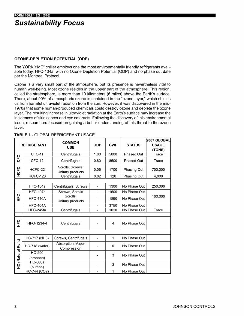
TABLE 1 - GloBal rEfriGErant usaGE
REFRIGERANT COMMON USE ODP GWP STATUS
2007 GLOBAL USAGE (TONS)
CFC
CfC-11 Centrifugals 1.00 5000 Phased out trace
CfC-12 Centrifugals 0.80 8500 Phased out trace
HC
FC hCfC-22scrolls, screws, unitary products
0.05 1700 Phasing out 700,000
hCfC-123 Centrifugals 0.02 120 Phasing out 4,000
HFC
hfC-134a Centrifugals, screws - 1300 no Phase out 250,000hfC-407c screws, scrolls - 1600 no Phase out
100,000hfC-410ascrolls,
unitary products- 1890 no Phase out
hfC-404a - 3750 no Phase outhfC-245fa Centrifugals - 1020 no Phase out trace
HFO hfo-1234yf Centrifugals - 4 no Phase out
HC
(Nat
ural
Ref
r.)
hC-717 (nh3) screws, Centrifugals - 1 no Phase out
hC-718 (water)absorption, Vapor
Compression- 0 no Phase out
hC-290 (propane)
- 3 no Phase out
hC-600a (butane)
- 3 no Phase out
hC-744 (Co2) - 1 no Phase out
FORM 160.84-EG1 (516)
JOHNSON CONTROLS 9
monitoring stations showed that ozone-depleting chemicals were steadily increasing in the atmosphere. these trends were linked to growing production and use of chemicals like chlorofluorocarbons (CfCs) for refrigeration and air conditioning, foam blowing, and industrial cleaning. measurements in the laboratory and the atmosphere characterized the chemical reactions that were involved in ozone destruction. Computer models em-ploying this information could predict how much ozone depletion was occurring and how much more could occur in the future.
observations of the ozone layer showed that depletion was indeed occurring. the most severe and most surprising ozone loss was discovered to be recurring in springtime over antarctica. the loss in this region is commonly called the “ozone hole” because the ozone depletion is so large and localized. a thinning of the ozone layer also has been observed over other regions of the globe, such as the arctic and northern middle latitudes. the work of many scientists throughout the world has provided a basis for building a broad and solid scientific understanding of the ozone depletion process. With this understanding, we know that ozone depletion is occurring and why. and, most important, we know that if ozone-depleting gases were to continue to accumulate in the atmosphere, the result would be more depletion of the ozone layer. in response to the prospect of increasing ozone depletion, the governments of the world crafted the 1987 united nations montreal Protocol as a global means to address this global issue. as a result of the broad compli-ance with the Protocol and its amendments and adjustments and, of great significance, industry’s development of “ozone friendly” substitutes for the now-controlled chemicals, the total global accumulation of ozone-depleting gases has slowed and begun to de-crease. this has reduced the risk of further ozone depletion.
THE MONTREAL PROTOCOL ADDRESSED CFC’S AND HCFC’S
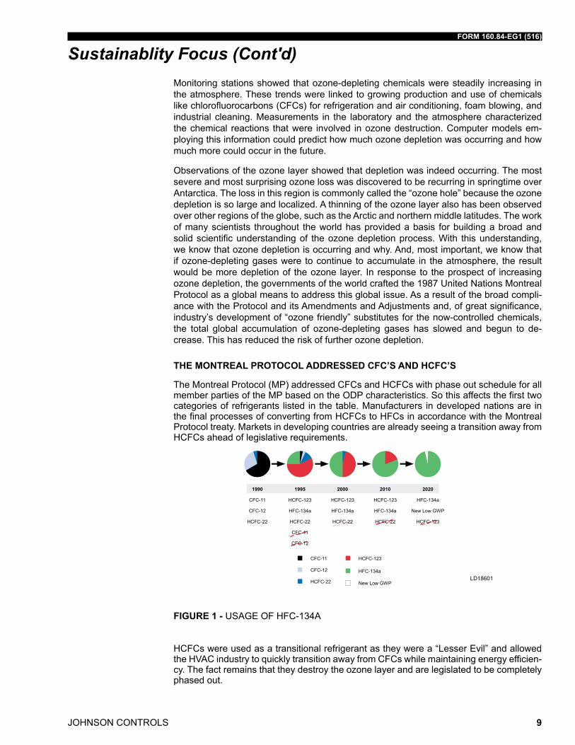
the montreal Protocol (mP) addressed CfCs and hCfCs with phase out schedule for all member parties of the mP based on the odP characteristics. so this affects the first two categories of refrigerants listed in the table. manufacturers in developed nations are in the final processes of converting from hCfCs to hfCs in accordance with the montreal Protocol treaty. markets in developing countries are already seeing a transition away from hCfCs ahead of legislative requirements.
ld18601
FIGURE 1 - usaGE of hfC-134a
hCfCs were used as a transitional refrigerant as they were a “lesser Evil” and allowed the hVaC industry to quickly transition away from CfCs while maintaining energy efficien-cy. the fact remains that they destroy the ozone layer and are legislated to be completely phased out.
Sustainablity Focus (Cont'd)
JOHNSON CONTROLS
FORM 160.84-EG1 (516)
10
Sustainablity Focus (Cont'd)the montreal Protocol does not extend to hfCs as they have no odP nor does it extend to natural refrigerants for the same reason.
the typical usage of the refrigerant, the phase-out status by the montreal Protocol and the global usage of refrigerant in tons is shown in the table on page 8.
the chart below shows the growing use of hfC-134a in centrifugal chillers from 1995 up to 2010 and the forecast until the phase-out of hCfCs.
ld18602
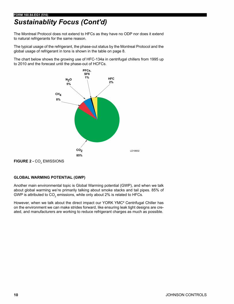
FIGURE 2 - Co2 Emissions
GLOBAL WARMING POTENTIAL (GWP)
another main environmental topic is Global Warming potential (GWP), and when we talk about global warming we’re primarily talking about smoke stacks and tail pipes. 85% of GWP is attributed to Co2 emissions, while only about 2% is related to hfCs.
however, when we talk about the direct impact our YorK YmC² Centrifugal Chiller has on the environment we can make strides forward, like ensuring leak tight designs are cre-ated, and manufacturers are working to reduce refrigerant charges as much as possible.
FORM 160.84-EG1 (516)
JOHNSON CONTROLS 11
DIRECT & INDIRECT GLOBAL WARMING POTENTIAL
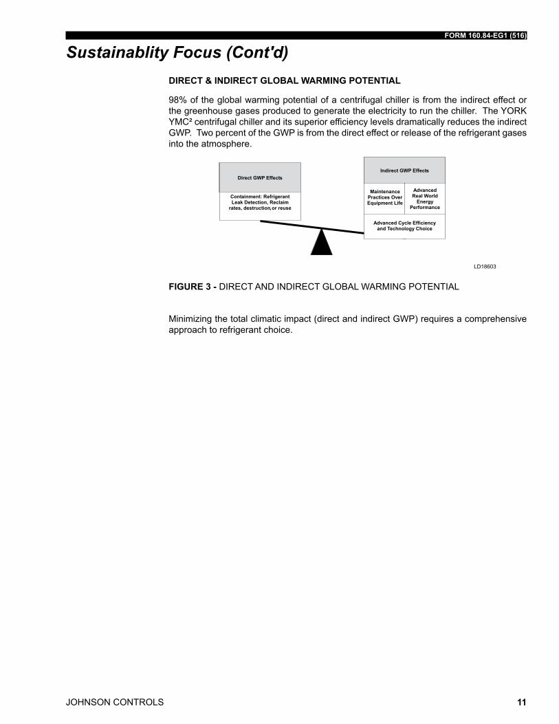
98% of the global warming potential of a centrifugal chiller is from the indirect effect or the greenhouse gases produced to generate the electricity to run the chiller. the YorK YmC² centrifugal chiller and its superior efficiency levels dramatically reduces the indirect GWP. two percent of the GWP is from the direct effect or release of the refrigerant gases into the atmosphere.
ld18603
,
FIGURE 3 - dirECt and indirECt GloBal WarminG PotEntial
minimizing the total climatic impact (direct and indirect GWP) requires a comprehensive approach to refrigerant choice.
Sustainablity Focus (Cont'd)
JOHNSON CONTROLS
FORM 160.84-EG1 (516)
12
Ratings
AHRI CERTIFICATION PROGRAM
the performance of the YmC² chiller has been certified to the air Conditioning, heating and refrigeration institute (ahri) as complying with the certification sections of the latest issue of ahri standard 550/590. under this Certification Program, chillers are regularly tested in strict compliance with this standard. this provides an independent, third-party verification of chiller performance.
COMPUTERIZED PERFORMANCE RATINGS
Each chiller is custom-matched to meet the individual building load and energy require-ments. a variety of standard heat exchangers and pass arrangements are available to provide the best possible match.
it is not practical to provide tabulated performance for each combination, as the energy requirements at both full and part-load vary significantly with each heat exchanger and pass arrangement. Computerized ratings are available through each Johnson Controls sales office. Each rating can be tailored to a specific job requirement, and is part of the ahri Certification Program.
TAKE ADVANTAGE OF COLDER COOLING TOWER WATER TEMPERATURES
the YmC² chillers have been designed to take full advantage of colder cooling tower water temperatures, which are naturally available during most operating hours. Consider-able energy savings are available by letting tower water temperature drop, rather than artificially holding it above 75°f (24°C), especially at low load, as some chillers require.
OFF-DESIGN PERFORMANCE
since the vast majority of its operating hours are spent at off-design conditions, a chiller should be chosen not only to meet the full load design, but also for its ability to perform ef-ficiently at lower loads and lower tower water temperatures. it is not uncommon for chillers with the same full load efficiency to have an operating cost difference of over 10% due to differences in off-design (part-load) efficiencies.
FORM 160.84-EG1 (516)
JOHNSON CONTROLS 13
Ratings (Cont'd)
ld18604
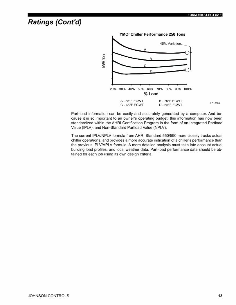
YMC² Chiller Performance 250 Tons
A - 85°F ECWTC - 65°F ECWT
B - 75°F ECWTD - 55°F ECWT
Part-load information can be easily and accurately generated by a computer. and be-cause it is so important to an owner’s operating budget, this information has now been standardized within the ahri Certification Program in the form of an integrated Partload Value (iPlV), and non-standard Partload Value (nPlV).
the current iPlV/nPlV formula from ahri standard 550/590 more closely tracks actual chiller operations, and provides a more accurate indication of a chiller's performance than the previous iPlV/aPlV formula. a more detailed analysis must take into account actual building load profiles, and local weather data. Part-load performance data should be ob-tained for each job using its own design criteria.
JOHNSON CONTROLS
FORM 160.84-EG1 (516)
14
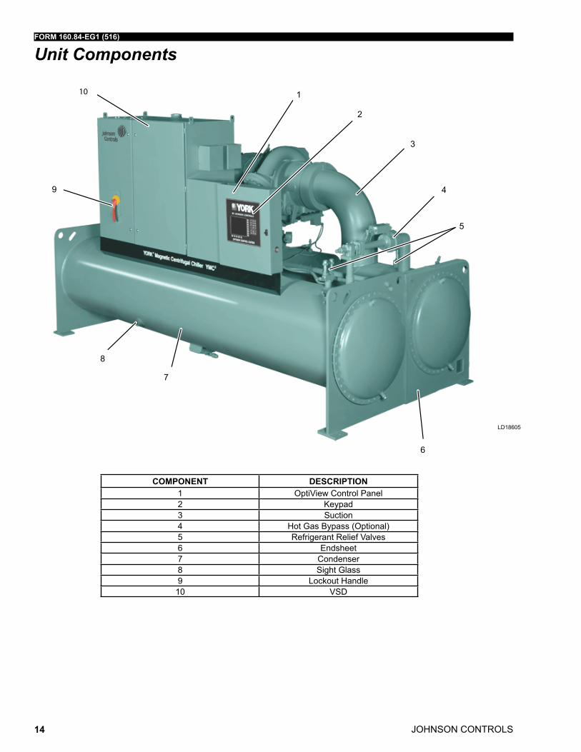
Unit Components
1
2
3
4
5
6
7
8
9
10
COMPONENT DESCRIPTION1 optiView Control Panel2 Keypad3 suction4 hot Gas Bypass (optional)5 refrigerant relief Valves6 Endsheet7 Condenser8 sight Glass9 lockout handle10 Vsd
ld18605
FORM 160.84-EG1 (516)
JOHNSON CONTROLS 15
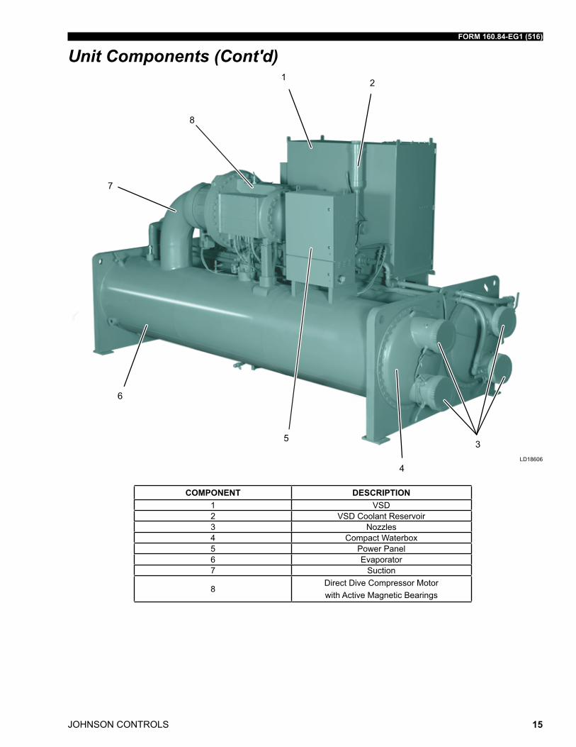
Unit Components (Cont'd)
COMPONENT DESCRIPTION1 Vsd2 Vsd Coolant reservoir3 nozzles4 Compact Waterbox5 Power Panel6 Evaporator7 suction
8direct dive Compressor motor with active magnetic Bearings
1 2
3
4
5
6
7
8
ld18606
JOHNSON CONTROLS
FORM 160.84-EG1 (516)
16
Equipment Overview
YorK YmC² Centrifugal liquid Chillers are completely factory-packaged including the evaporator, condenser, compressor, motor, Vsd, control center, and all interconnecting unit piping and wiring.
the initial charge of refrigerant is supplied for each chiller. actual shipping procedures for the chiller will depend on a number of project-specific details.
the services of a Johnson Controls factory-trained, field service representative are in-curred to supervise or perform the final leak testing, charging, the initial start-up, and concurrent operator instructions.
COMPRESSOR
the compressor is a single-stage centrifugal type directly driven by a hermetically-sealed, permanent-magnet motor. a cast-aluminum, fully-shrouded impeller is mounted directly to the motor shaft using a stretched tie-bolt. impeller seals employ a labyrinth geometry, sized to provide minimal thrust loading on the impeller throughout the operating range. the impeller is dynamically balanced and overspeed tested for smooth, vibration-free operation.
CAPACITy CONTROL
Capacity control will be achieved by the combined use of variable speed control and mechanical flow regulation to provide fully modulating control from maximum to minimum load. for normal air conditioning applications, the chiller can adjust capacity from 100% to 15% of design. for each condition the capacity control devices will be automatically adjusted to maintain a constant leaving chilled liquid tem perature at optimized efficiency, based on information fed by sensors located throughout the chiller.
all mechanical actuators are external electrical devices which automatically and precisely position components.
MOTOR
the compressor motor is a hermetically-sealed, high-speed design with a permanent magnet rotor supported by active magnetic bearings. Each magnetic bearing cartridge includes both radial and axial (thrust) bearings. the bearing controls provide a completely oil-free operating system. the motor rotor and stator are cooled by a pressure driven re-frigerant loop to maintain acceptable operating temperatures.
the active magnetic bearings are equipped with automatic vibration reduction and bal-ancing systems to ensure smooth and reliable operation. in the event of a power failure, the magnetic bearings will remain in operation throughout the compressor coast-down us-ing a reserve energy supply. mechanical bearings are included as backup to the magnetic bearings and designed for emergency touchdown situations.
The active magnetic bearings are equipped with automatic vibration redution and balancing systems
FORM 160.84-EG1 (516)
JOHNSON CONTROLS 17
Equipment Overview (Cont'd)OPTISOUND CONTROL
YmC² chillers are equipped with the YorK optisound Control as standard. the YorK optisound Control is a patented combination of centrifugal-chiller hardware and software that reduces operational sound levels, expands the chiller operating range, and improves chiller performance. the optisound Control feature continuously monitors the charac-teristics of the compressor-discharge gas and optimizes the diffuser spacing to minimize gas-flow disruptions from the impeller. this innovative technology improves operating sound levels of the chiller and can reduce part-load sound levels below the full-load level.
in addition, the optisound Control provides the benefit of an expanded operating range. it improves performance and reliability by minimizing diffuser-gas stall at off-design op-eration, particularly at conditions of very low load combined with little or no condenser-water relief. the elimination of the gas-stall condition can also result in improved chiller efficiency at off design conditions.
OptiSpeed VSD
a Vsd is factory-packaged and mounted on the YmC² chiller. it is designed to vary the compressor motor speed by controlling the frequency and voltage of the electrical power to the motor. the capacity control logic shall automatically adjust motor speed and com-pressor diffuser geometry for maximum part-load efficiency by analyzing information fed to it by sensors located throughout the chiller. see OptiView Control Center on page 21 for additional information.
HEAT EXCHANGERS
Shells
Evaporator and condenser shells are fabricated from rolled carbon steel plates with fu-sion welded seams or carbon steel pipe. Carbon steel tube sheets, drilled and reamed to accommodate the tubes, are welded to the end of each shell. intermediate tube supports are fabricated from carbon steel plates, drilled and reamed to eliminate sharp edges. the refrigerant side of each shell is designed, tested, and stamped in accordance with asmE Boiler and Pressure Vessel Code, section Viii – division i, or other pressure vessel code as appropriate.
Tubes
heat exchanger tubes are copper alloy high-efficiency, externally and internally enhanced type to provide optimum performance. utilizing the “skip-fin” tube design provides a smooth internal and external surface at each intermediate tube support. this provides extra wall thickness (up to twice as thick) and non work-hardened copper at the support location, extending the life of the heat exchangers. Each tube is roller-expanded into the tube sheets providing a leak-proof seal, and is individually replaceable.
Evaporator
the evaporator is a shell and tube, hybrid falling-film type heat exchanger. it contains a balance of flooded and falling-film technology to optimize efficiency, minimize refrigerant charge, and maintain reliable control. a specifically designed spray distributor provides uniform distribution of refrigerant over the entire shell length to yield optimum heat trans-fer. a suction baffle is located above the tube bundle to prevent liquid refrigerant carryover
JOHNSON CONTROLS
FORM 160.84-EG1 (516)
18
into the compressor. a 1-1/2" (38 mm) liquid level sight glass is conveniently located on the side of the shell to aid in determining proper refrigerant charge. the evaporator shell contains a dual refrigerant relief valve arrangement or a single-relief valve arrangement, if the chiller is supplied with the optional refrigerant isolation valves. a 1" (25.4 mm) refriger-ant charging valve is provided for service access.
Condenser
the condenser is a shell and tube type, with a discharge gas baffle to prevent direct high velocity impingement on the tubes. the baffle is also used to distribute the refrigerant gas flow properly for the most efficient heat transfer. an integral sub-cooler is located at the bottom of the condenser shell providing highly effective liquid refrigerant subcooling to provide the highest cycle efficiency. a 1-1/2" (38 mm) liquid level sight glass is conve-niently located on the side of the shell to aid in determining proper refrigerant charge. the condenser contains dual refrigerant relief valves.
Water Boxes
the removable water boxes are fabricated of steel. integral steel water baffles are located and welded within the water box to provide the required pass arrangements. stub-out water nozzle connections welded to the water boxes are suitable for ansi/aWWa C-606 couplings, welding or flanged, and are capped for protection during shipment. Plugged 3/4" (19 mm) drain and vent connections are provided in each water box.
REFRIGERANT ISOLATION VALVES
factory-installed isolation valves in the compressor discharge line and refrigerant liquid line allow isolation and storage of the refrigerant charge in the chiller condenser.
WATER FLOW SWITCHES
thermal type water flow switches are factory mounted in the chilled and condenser water nozzles, and are factory wired to the optiView control panel. these solid state flow sen-sors have a small internal heating element. they use the cooling effect of the flowing fluid to sense when an adequate flow rate has been established. the sealed sensor probe is 316 stainless steel, which is suited to very high working pressures.
REFRIGERANT FLOW CONTROL
refrigerant flow to the evaporator is controlled by the YorK variable orifice control sys-tem. liquid refrigerant level is continuously monitored to provide optimum subcooler, condenser and evaporator performance. the variable orifice electronically adjusts to all real-World operating conditions, providing the most efficient and reliable operation of refrigerant flow control.
OPTIVIEW CONTROL CENTER
the chiller is controlled by a stand-alone, microprocessor-based control center. the con-trol center provides control of chiller operation and monitoring of chiller sensors, actua-tors, relays and switches. see OptiView Control Center on page 21 for additional infor-mation.
Equipment Overview (Cont'd)
FORM 160.84-EG1 (516)
JOHNSON CONTROLS 19
Equipment Overview (Cont'd)CODES AND STANDARDS
• asmE Boiler and Pressure Vessel Code – section Vlll division 1.
• ahri standard 550/590
• c/u.l. – underwriters laboratory
• ashraE 15 – safety Code for mechanical refrigeration
• ashraE Guideline 3 – reducing Emission of halogenated refrigerants in refrig-eration and air-Conditioning Equipment and systems
• n.E.C. – national Electrical Code
• osha – occupational safety and health act
• iEEE std. 519-1992 Compliance
ISOLATION MOUNTING
the unit is provided with four vibration isolation mounts of nominal 1" operating height. the pads have a neoprene pad to contact the foundation, bonded to a steel plate. the vibration isolation pad assemblies mount under steel plates welded to the chiller tube sheets.
REFRIGERANT CONTAINMENT
the standard unit has been designed as a complete and compact factory-packaged chill-er. as such, it has minimum joints from which refrigerant can leak. the entire assembly has been thoroughly leak tested at the factory prior to shipment. the YmC² chiller includes service valves conveniently located to facilitate transfer of refrigerant to a remote refriger-ant storage/recycling system. Condenser isolation valves allow storage of the charge in the condenser.
PAINT
Exterior surfaces are protected with one coat of Caribbean blue, durable alkyd-modified, vinyl enamel, machinery paint.
SHIPMENT
Protective covering is furnished on the Control Center, Vsd, and unit-mounted controls. Water nozzles are capped with fitted plastic enclosures. Entire unit is protected with in-dustrial-grade, reinforced shrinkwrap covering. Each unit can be broken down into several form shipment configureations for ease of transportation and installation.
FORM 3 – Driveline Separate from Shells
shipped as three major assemblies:
• driveline (motor/compressor assembly)
• Evaporator/Condenser shell assembly
• Variable speed drive
JOHNSON CONTROLS
FORM 160.84-EG1 (516)
20
the unit is first factory assembled, refrigerant piped, wired and leak tested; then disman-tled for shipment. Close-coupled compressor/hermetic motor assembly removed from shells and skidded. Evaporator/condenser is not skidded.
FORM 7 – Driveline Separate from Split Shells
shipped as four major assemblies:
• driveline (motor/compressor assembly)
• Evaporator
• Condenser
• Variable speed drive
the unit is first factory assembled, refrigerant piped, wired and leak tested; then disman-tled for shipment. Close-coupled compressor/hermetic motor assembly removed from shells and skidded.
FORM 9 – Unit Separate from Variable Speed Drive (Refrigerant Shipped Separate)
shipped as two major assemblies:
• Chiller unit
• Variable speed drive
the unit is first factory assembled, refrigerant piped, wired and leak tested; then disman-tled for shipment. Evaporator/condenser is not skidded.
FORM 10 – Unit Separate from Variable Speed Drive (Unit Charged with Refrigerant)
shipped as two major assemblies:
• Chiller unit
• Variable speed drive
the unit is first factory assembled, refrigerant piped, wired and leak tested; then disman-tled for shipment. Evaporator/condenser is not skidded.
FORM 11 – Split Shells
shipped as two major assemblies:
• Condenser side assembly (Condenser/optiView/Variable speed drive)
• Evaporator side assembly (Evaporator/driveline/magnetic Bearing Controller)
the unit is first factory assembled, refrigerant piped, wired and leak tested; then disman-tled for shipment. Evaporator/condenser is not skidded.
Equipment Overview (Cont'd)
FORM 160.84-EG1 (516)
JOHNSON CONTROLS 21
OptiView Control Center
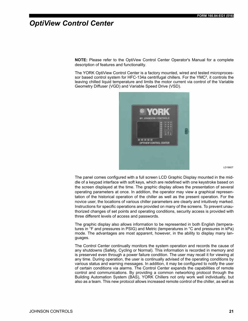
NOTE: Please refer to the optiVew Control Center operator's manual for a complete description of features and functionality.
the YorK optiView Control Center is a factory mounted, wired and tested microproces-sor based control system for hfC-134a centrifugal chillers. for the YmC², it controls the leaving chilled liquid temperature and limits the motor current via control of the Variable Geometry diffuser (VGd) and Variable speed drive (Vsd).
ld18607
the panel comes configured with a full screen lCd Graphic display mounted in the mid-dle of a keypad interface with soft keys, which are redefined with one keystroke based on the screen displayed at the time. the graphic display allows the presentation of several operating parameters at once. in addition, the operator may view a graphical represen-tation of the historical operation of the chiller as well as the present operation. for the novice user, the locations of various chiller parameters are clearly and intuitively marked. instructions for specific operations are provided on many of the screens. to prevent unau-thorized changes of set points and operating conditions, security access is provided with three different levels of access and passwords.
the graphic display also allows information to be represented in both English (tempera-tures in °f and pressures in PsiG) and metric (temperatures in °C and pressures in kPa) mode. the advantages are most apparent, however, in the ability to display many lan-guages.
the Control Center continually monitors the system operation and records the cause of any shutdowns (safety, Cycling or normal). this information is recorded in memory and is preserved even through a power failure condition. the user may recall it for viewing at any time. during operation, the user is continually advised of the operating conditions by various status and warning messages. in addition, it may be configured to notify the user of certain conditions via alarms. the Control Center expands the capabilities of remote control and communications. By providing a common networking protocol through the Building automation system (Bas), YorK Chillers not only work well individually, but also as a team. this new protocol allows increased remote control of the chiller, as well as
JOHNSON CONTROLS
FORM 160.84-EG1 (516)
22
24-hour performance monitoring via a remote site. in addition, compatibility is maintained with the present network of Bas communications. the chiller also maintains the standard digital remote capabilities as well. Both of these remote control capabilities allow for the standard Energy management system (Ems) interface:
1. remote start
2. remote stop
3. remote leaving Chilled liquid temperature setpoint adjustment (0 to 10VdC, 2 to 10VdC, 0 to 20ma or 4 to 20ma) or Pulse Width modulation
4. remote Current limit setpoint adjustment
5. (0 to 10VdC, 2 to 10VdC, 0 to 20ma or 4 to 20ma) or Pulse Width modulation
6. remote rEadY to start Contacts
7. safety shutdown Contacts
8. Cycling shutdown Contacts
the following are examples of the information displayed on some of the more important screens:
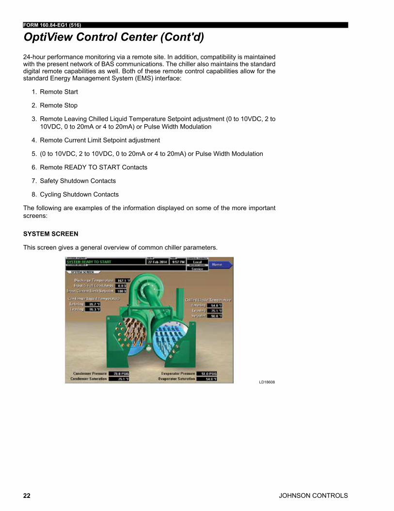
SySTEM SCREEN
this screen gives a general overview of common chiller parameters.
ld18608
OptiView Control Center (Cont'd)
FORM 160.84-EG1 (516)
JOHNSON CONTROLS 23
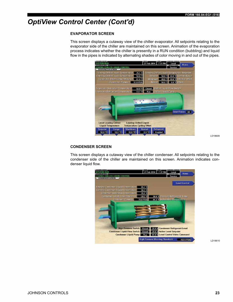
EVAPORATOR SCREEN
this screen displays a cutaway view of the chiller evaporator. all setpoints relating to the evaporator side of the chiller are maintained on this screen. animation of the evaporation process indicates whether the chiller is presently in a run condition (bubbling) and liquid flow in the pipes is indicated by alternating shades of color moving in and out of the pipes.
ld18609
CONDENSER SCREEN
this screen displays a cutaway view of the chiller condenser. all setpoints relating to the condenser side of the chiller are maintained on this screen. animation indicates con-denser liquid flow.
ld18610
OptiView Control Center (Cont'd)
JOHNSON CONTROLS
FORM 160.84-EG1 (516)
24
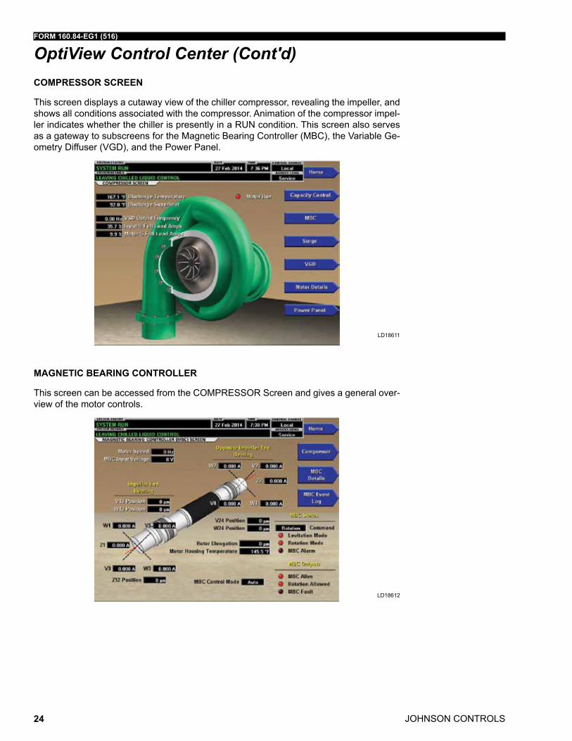
COMPRESSOR SCREEN
this screen displays a cutaway view of the chiller compressor, revealing the impeller, and shows all conditions associated with the compressor. animation of the compressor impel-ler indicates whether the chiller is presently in a run condition. this screen also serves as a gateway to subscreens for the magnetic Bearing Controller (mBC), the Variable Ge-ometry diffuser (VGd), and the Power Panel.
ld18611
MAGNETIC BEARING CONTROLLER
this screen can be accessed from the ComPrEssor screen and gives a general over-view of the motor controls.
ld18612
OptiView Control Center (Cont'd)
FORM 160.84-EG1 (516)
JOHNSON CONTROLS 25
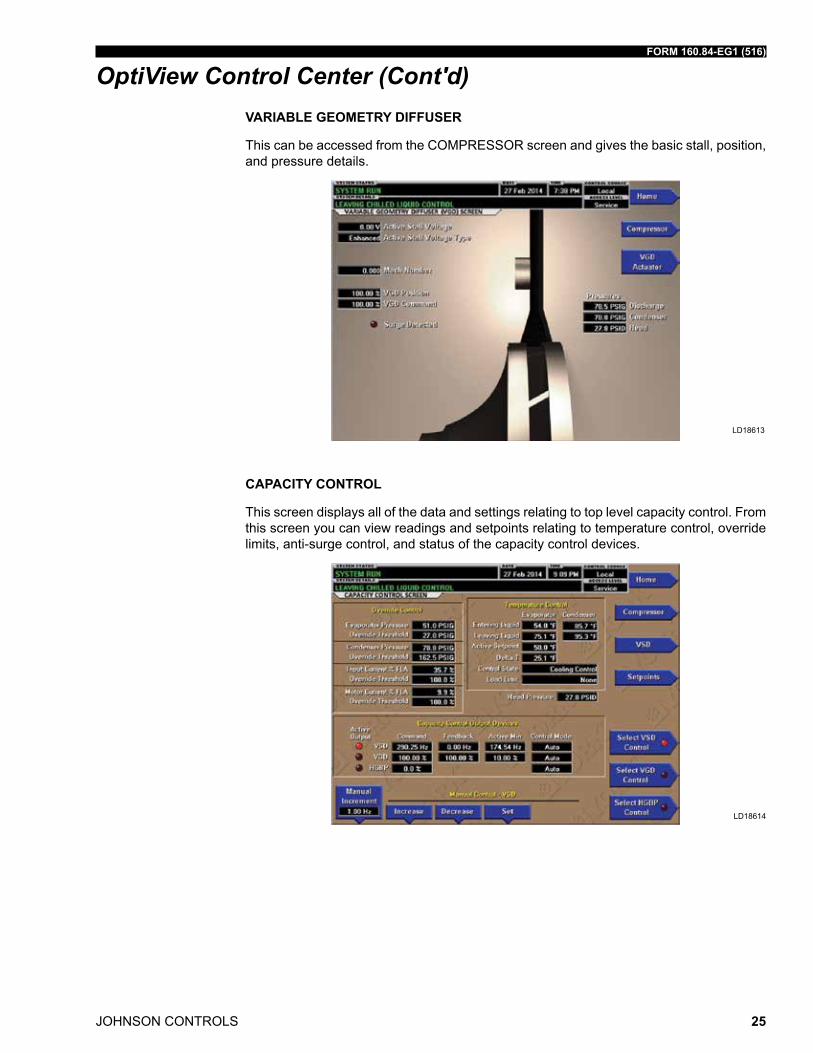
VARIABLE GEOMETRy DIFFUSER
this can be accessed from the ComPrEssor screen and gives the basic stall, position, and pressure details.
ld18613
CAPACITy CONTROL
this screen displays all of the data and settings relating to top level capacity control. from this screen you can view readings and setpoints relating to temperature control, override limits, anti-surge control, and status of the capacity control devices.
ld18614
OptiView Control Center (Cont'd)
JOHNSON CONTROLS
FORM 160.84-EG1 (516)
26
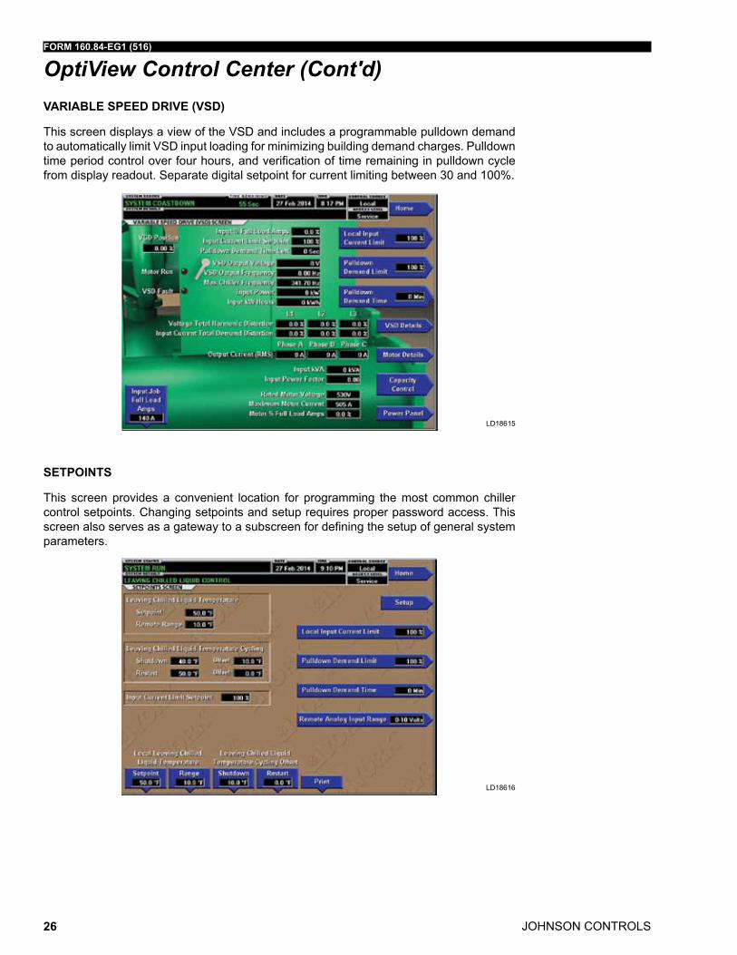
VARIABLE SPEED DRIVE (VSD)
this screen displays a view of the Vsd and includes a programmable pulldown demand to automatically limit Vsd input loading for minimizing building demand charges. Pulldown time period control over four hours, and verification of time remaining in pulldown cycle from display readout. separate digital setpoint for current limiting between 30 and 100%.
ld18615
SETPOINTS
this screen provides a convenient location for programming the most common chiller control setpoints. Changing setpoints and setup requires proper password access. this screen also serves as a gateway to a subscreen for defining the setup of general system parameters.
ld18616
OptiView Control Center (Cont'd)
FORM 160.84-EG1 (516)
JOHNSON CONTROLS 27
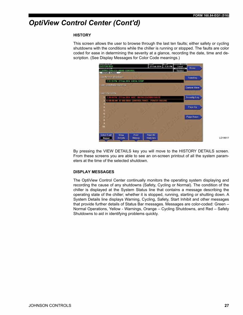
HISTORy
this screen allows the user to browse through the last ten faults; either safety or cycling shutdowns with the conditions while the chiller is running or stopped. the faults are color coded for ease in determining the severity at a glance, recording the date, time and de-scription. (see display messages for Color Code meanings.)
ld18617
By pressing the ViEW dEtails key you will move to the historY dEtails screen. from these screens you are able to see an on-screen printout of all the system param-eters at the time of the selected shutdown.
DISPLAy MESSAGES
the optiView Control Center continually monitors the operating system displaying and recording the cause of any shutdowns (safety, Cycling or normal). the condition of the chiller is displayed at the system status line that contains a message describing the operating state of the chiller; whether it is stopped, running, starting or shutting down. a system details line displays Warning, Cycling, safety, start inhibit and other messages that provide further details of status Bar messages. messages are color-coded: Green – normal operations, Yellow - Warnings, orange – Cycling shutdowns, and red – safety shutdowns to aid in identifying problems quickly.
OptiView Control Center (Cont'd)
JOHNSON CONTROLS
FORM 160.84-EG1 (516)
28
OptiSpeed Variable-Speed Drive
the new YorK optispeed Vsd is a liquid-cooled, insulated-gate, bipolar-transistor-based (iGBt), pulse-width-modulated (PWm) rectifier/inverter in a highly integrated pack-age. this package is small enough to mount directly onto the chiller. the power section of the drive is composed of four major blocks: a three-phase aC-to-dC rectifier section with an integrated input filter and precharge circuit, a dC link filter section, a three-phase dC to aC inverter section, and an output sine filter-network.
an input disconnect device connects the aC line to an input filter and then to the aC-to-dC three-phase PWm rectifier. the disconnect device can be a three-phase rotary disconnect switch (standard), or an electronic circuit breaker (optional). the inductors in the input fil-ter limit the amount of fault current into the Vsd; however, for the additional protection of the PWm rectifier’s iGBt transistors, semiconductor fuses are provided between the input disconnect device and input filter. the three-phase PWm rectifier uses iGBt transistors, mounted on a liquid-cooled heat sink and controlled at a high frequency, to convert aC line voltage into a tightly regulated dC voltage. additionally, the PWm rectifier shapes the line current into an almost-sinusoidal waveform, allowing the Vsd to produce low levels of harmonic distortion while helping the building comply with the requirements of the iEEE std 519-1992, “iEEE recommended Practices and requirements for harmonic Control in Electrical Power systems”. the PWm rectifier also contains a proprietary precharge circuit, which keeps the inrush current into the Vsd at a minimal value, well below the nominal.
the dC link filter section of the drive consists of one basic component, a bank of filter capacitors. the capaci- tors provide an energy reservoir for use by the dC to aC inverter section of the optispeed drive. the capacitors are contained in the optispeed Power Pole, as are the “bleeder” resistors, which provides a discharge path for the stored energy in the capacitors.
the dC to aC PWm inverter section of the optispeed serves to convert the dC voltage to aC voltage at the proper magnitude and frequency as commanded by the optispeed logic board. the inverter section consists of fast switching iGBt transistors mounted on a liquid cooled heat sink. the optispeed Power Pole is composed of the inverter iGBt modules (with heat sink), the rectifier iGBt modules (with heat sink), the dC link filter capacitor, the “bleeder” resistors, the laminated interconnecting buss bar, and the optispeed Gate driver board. the optispeed Gate driver board provides the turn-on and turn-off commands to the rectifier’s and inverter’s transistors. the optispeed logic board determines when the turn-on, and turn-off commands should occur. additionally, the optispeed logic board monitors the status of the optispeed Vsd system, generates all optispeed system faults (including the ground fault), and communicates with optiView control panel.
FORM 160.84-EG1 (516)
JOHNSON CONTROLS 29
OptiSpeed Variable-Speed Drive (Cont'd)the optispeed output sine filter network is composed of inductors and capacitors. the job of the output filter network is to eliminate voltage harmonics from the inverter’s output, and provide a high-quality, almost-sinusoidal voltage to the motor. this completely eliminates all issues related to premature motor insulation failures due to high voltage peaks gen-erated by the inverter, and it additionally allows the motor to run cooler, thus increasing system reliability.
other sensors and boards are used to provide safe operation of the optispeed drive. the iGBt transistor modules have thermistors mounted on them that provide information to the optispeed logic board. these sensors, as well as additional thermistors monitor-ing the internal ambient temperature, protect the optispeed from overtemperature con-ditions. a voltage sensor is used to ensure that the dC link filter capacitors are properly charged. three input and three output current transformers protect the drive and motor from over current conditions.
JOHNSON CONTROLS
FORM 160.84-EG1 (516)
30
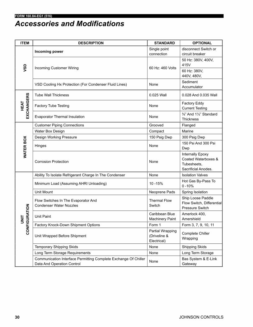
Accessories and Modifications
ITEM DESCRIPTION STANDARD OPTIONAL
VSD
Incoming power single point connection
disconnect switch or circuit breaker
incoming Customer Wiring 60 hz: 460 Volts
50 hz: 380V, 400V, 415V60 hz: 380V, 440V, 480V,
Vsd Cooling hx Protection (for Condenser fluid lines) nonesediment accumulator
HEA
T EX
CH
AN
GER
S tube Wall thickness 0.025 Wall 0.028 and 0.035 Wall
factory tube testing nonefactory Eddy Current testing
Evaporator thermal insulation none¾” and 1½” standard thickness
WAT
ER B
OX
Customer Piping Connections Grooved flangedWater Box design Compact marinedesign Working Pressure 150 Psig dwp 300 Psig dwp
hinges none150 Psi and 300 Psi dwp
Corrosion Protection none
internally Epoxy Coated Waterboxes & tubesheets, SacrificialAnodes.
UN
IT
CO
NFI
GU
RAT
ION
ability to isolate refrigerant Charge in the Condenser none isolation Valves
minimum load (assuming ahri unloading) 10 -15%hot Gas By-Pass to 0 -10%
unit mount neoprene Pads spring isolation
flow switches in the Evaporator and Condenser Water nozzles
thermal flow switch
ship loose Paddle flow switch, differential Pressure switch
unit PaintCaribbean Bluemachinery Paint
amerlock 400, amershield
factory Knock-down shipment options form 1 form 3, 7, 9, 10, 11
unit Wrapped Before shipmentPartial Wrapping (driveline & Electrical)
Complete Chiller Wrapping
temporary shipping skids none shipping skidslong term storage requirements none long term storageCommunication interface Permitting Complete Exchange of Chiller data and operation Control
noneBas system & E-linkGateway
FORM 160.84-EG1 (516)
JOHNSON CONTROLS 31
Application Data
the following discussion is a user’s guide in the application and installation of YmC² chill-ers to ensure the reliable, trouble-free life for which this equipment was designed. While this guide is directed towards normal, water-chilling applications, a Johnson Controls sales engineer can provide complete recommendations on other types of applications.
LOCATION
YmC² chillers are virtually vibration free and may generally be located at any level in a building where the construction will support the total system operating weight.
the unit site must be a floor, mounting pad or foundation which is level within 1/4" (6.4 mm) and capable of supporting the operating weight of the unit.
sufficient clearance to permit normal service and maintenance work should be provided all around and above the unit. additional space should be provided at one end of the unit to permit cleaning of evaporator and condenser tubes as required. a doorway or other properly located opening may be used.
the chiller should be installed in an indoor location where temperatures range from 40°f to 104°f (4.4°C to 40°C). the dew point temperature in the equipment room must be be-low the entering condenser water temperature to prevent condensing water vapor inside of the Vsd. applications using cooling sources other than evaporative or closed loop air exchange methods need to request a factory-supplied temperature control valve to pre-vent condensation inside the Vsd. other areas susceptible to water vapor condensate are outside of the condenser shell and condenser water boxes. Example applications include cooling condenser water using chilled water, wells, river, or other low temperature fluids.
for outdoor applications, please contact the large tonnage application team.
WATER CIRCUITS
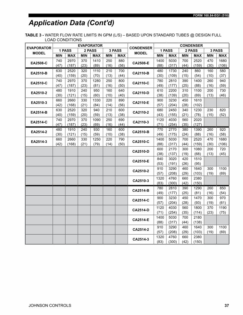
Flow Rate – for normal water chilling duty, evaporator and condenser flow rates are per-mitted at water velocity levels in the heat exchangers tubes of between 3 ft/sec (3.3 for condensers) and 12 ft/sec (0.91 m/s and 3.66 m/s). two-pass units are also limited to 45 ft h20 (134 kPa) water pressure drop. the three pass limit is 67.5 ft h20 (201 kPa). Variable flow in the condenser is not recommended, as it generally raises the energy consumption of the system by keeping the condenser pressure high in the chiller. additionally, the rate of fouling in the condenser will increase at lower water velocities associated with variable flow, raising system maintenance costs. Cooling towers typically have narrow ranges of operation with respect to flow rates, and will be more effective with full design flow. ref. table 1 for flow limits at design conditions.
there is increasing interest to use variable primary flow (VPf) systems in large chilled water plants. VPf systems can offer lower installation and operating costs in many cases, but do require more sophisticated control and flow monitoring. YmC² chillers will operate successfully in VPf systems. With a minimum allowable evaporator tube velocity of 1-1/2 fps (0.5 m/s) for standard tubes at part-load rating conditions, YmC² chillers will accom-modate the wide variation in flow required by many chilled water VPf applications.
JOHNSON CONTROLS
FORM 160.84-EG1 (516)
32
the chillers can tolerate a 50% flow rate change in one minute that is typically associ-ated with the staging on or off of an additional chiller; however a lower flow rate change is normally used for better system stability and set point control. Proper sequencing via the building automation system will make this a very smooth transition.
Temperature Ranges – for normal water chilling duty, leaving chilled water tempera-tures may be selected between 38°f (3.3°C) [36°f (2.2°C) with smart freeze enabled] and 70°f (21.1°C) to obtain temperature deltas between entering chilled and leaving chilled water temperature of 3°f up to 30°f (1.7°C and 16.7°C).
Water quality – the practical and economical application of liquid chillers requires that the quality of the water supply for the condenser and evaporator be analyzed by a water treatment specialist. Water quality may affect the performance of any chiller through cor-rosion, deposition of heat-resistant scale, sedimentation or organic growth. these will degrade chiller performance and increase operating and maintenance costs. normally, performance may be maintained by corrective water treatment and periodic cleaning of tubes. if water conditions exist which cannot be corrected by proper water treatment, it may be necessary to provide a larger allowance for fouling, and/or to specify special ma-terials of construction.
General Piping – all chilled water and condenser water piping should be designed and installed in accordance with accepted piping practice. Chilled water and condenser wa-ter pumps should be located to discharge through the chiller to assure positive pressure and flow through the unit. Piping should include offsets to provide flexibility and should be arranged to prevent drainage of water from the evaporator and condenser when the pumps are shut off. Piping should be adequately supported and braced independently of the chiller to avoid the imposition of strain on chiller components. hangers must allow for alignment of the pipe. isolators in the piping and in the hangers are highly desirable in achieving sound and vibration control.
Convenience Considerations – to facilitate the performance of routine maintenance work, some or all of the following steps may be taken by the purchaser. Evaporator and condenser water boxes are equipped with plugged vent and drain connections. if desired, vent and drain valves may be installed with or without piping to an open drain. Pressure gauges with stop-cocks and stop-valves may be installed in the inlets and outlets of the condenser and chilled water line as close as possible to the chiller. an overhead monorail or beam may be used to facilitate servicing.
Connections – the standard chiller is designed for 150 psig (10.3 barg) design working pressure in both the chilled water and condenser water circuits. the connections (water nozzles) to these circuits are furnished with grooves to ansi/aWWa C-606 standard for grooved and shouldered joints. Piping should be arranged for ease of disassembly at the unit for tube cleaning. all water piping should be thoroughly cleaned of all dirt and debris before final connections are made to the chiller.
Chilled Water – a water strainer of maximum 1/8" (3.2 mm) perforated holes must be field-installed in the chilled water inlet line as close as possible to the chiller. if located close enough to the chiller, the chilled water pump may be protected by the same strainer. the strainer is important to protect the chiller from debris or objects which could block flow through individual heat exchanger tubes. a reduction in flow through tubes could seriously impair the chiller performance or even result in tube freeze-up. a thermal-type flow switch is factory installed in the evaporator nozzle and connected to the optiView panel, which assures adequate chilled water flow during operation.
Application Data (Cont'd)
FORM 160.84-EG1 (516)
JOHNSON CONTROLS 33
Application Data (Cont'd)Condenser Water – the chiller is engineered for maximum efficiency at both design and part-load operation by taking advantage of the colder cooling tower water temperatures which naturally occur during the winter months. appreciable power savings are realized from these reduced heads.
the minimum entering condenser water temperature for other full and part-load condi-tions is provided by the following equation:
where:
ECWT = entering condensing water temperature LCHWT = leaving chilled water temperature
at initial startup, entering condensing water temperature may be as much as 30°f (16.66°C) colder than the standby chilled water temperature.
Min ECWT = LCHWT -30°F (16.66°C)
MULTIPLE UNITS
Selection – many applications require multiple units to meet the total capacity require-ments as well as to provide flexibility and some degree of protection against equipment shutdown. there are several common unit arrangements for this type of application. the YmC² chiller has been designed to be readily adapted to the requirements of these vari-ous arrangements.
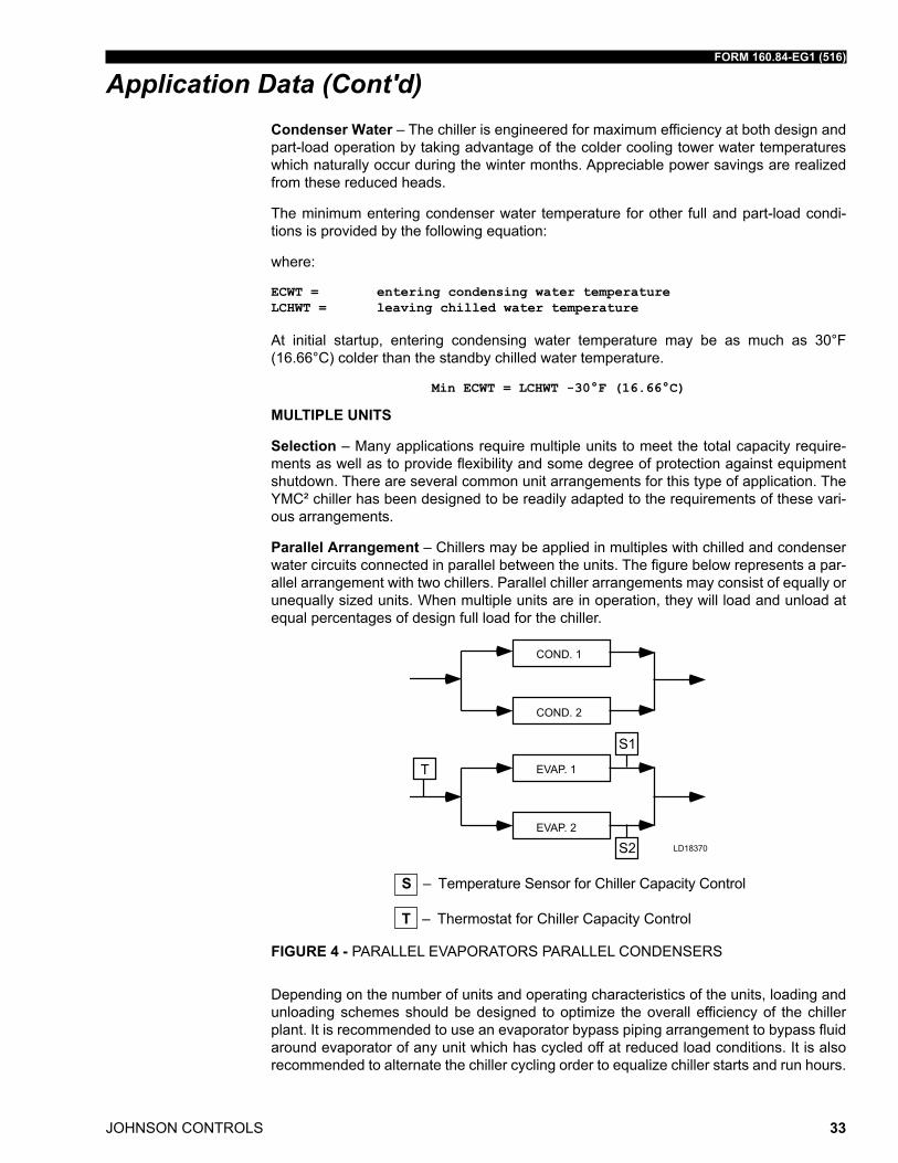
Parallel Arrangement – Chillers may be applied in multiples with chilled and condenser water circuits connected in parallel between the units. the figure below represents a par-allel arrangement with two chillers. Parallel chiller arrangements may consist of equally or unequally sized units. When multiple units are in operation, they will load and unload at equal percentages of design full load for the chiller.
COND. 1
COND. 2
EVAP. 1
EVAP. 2
LD18370
S – temperature sensor for Chiller Capacity Control
T – thermostat for Chiller Capacity Control
FIGURE 4 - ParallEl EVaPorators ParallEl CondEnsErs
depending on the number of units and operating characteristics of the units, loading and unloading schemes should be designed to optimize the overall efficiency of the chiller plant. it is recommended to use an evaporator bypass piping arrangement to bypass fluid around evaporator of any unit which has cycled off at reduced load conditions. it is also recommended to alternate the chiller cycling order to equalize chiller starts and run hours.
JOHNSON CONTROLS
FORM 160.84-EG1 (516)
34
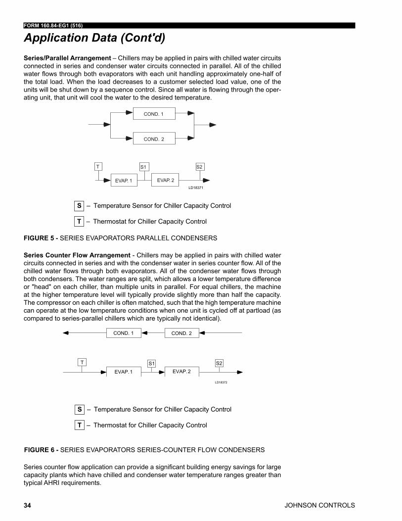
Series/Parallel Arrangement – Chillers may be applied in pairs with chilled water circuits connected in series and condenser water circuits connected in parallel. all of the chilled water flows through both evaporators with each unit handling approximately one-half of the total load. When the load decreases to a customer selected load value, one of the units will be shut down by a sequence control. since all water is flowing through the oper-ating unit, that unit will cool the water to the desired temperature.
EVAP. 1 EVAP. 2
T S1 S2
COND. 1
COND. 2
LD18371
S – temperature sensor for Chiller Capacity Control
T – thermostat for Chiller Capacity Control
FIGURE 5 - sEriEs EVaPorators ParallEl CondEnsErs
Series Counter Flow Arrangement - Chillers may be applied in pairs with chilled water circuits connected in series and with the condenser water in series counter flow. all of the chilled water flows through both evaporators. all of the condenser water flows through both condensers. the water ranges are split, which allows a lower temperature difference or "head" on each chiller, than multiple units in parallel. for equal chillers, the machine at the higher temperature level will typically provide slightly more than half the capacity. the compressor on each chiller is often matched, such that the high temperature machine can operate at the low temperature conditions when one unit is cycled off at partload (as compared to series-parallel chillers which are typically not identical).
LD18372
S – temperature sensor for Chiller Capacity Control
T – thermostat for Chiller Capacity Control
FIGURE 6 - sEriEs EVaPorators sEriEs-CountEr floW CondEnsErs
series counter flow application can provide a significant building energy savings for large capacity plants which have chilled and condenser water temperature ranges greater than typical ahri requirements.
Application Data (Cont'd)
FORM 160.84-EG1 (516)
JOHNSON CONTROLS 35
Application Data (Cont'd)REFRIGERANT RELIEF PIPING
Each chiller is equipped with dual pressure relief valves on the condenser and two dual relief valves on the evaporator, or two single relief valves on the evaporator if the optional refrigerant isolation valves are ordered. the dual relief valves on the condenser are re-dundant and allow changing of either valve while the unit is fully charged. the purpose of the relief valves is to quickly relieve excess pressure of the refrigerant charge to the atmosphere, as a safety precaution in the event of an emergency such as a fire. they are set to relieve at an internal pressure as noted on the pressure vessel data plate, and are provided in accordance with ashraE 15 safety code and asmE or applicable pressure vessel code.
sized to the requirements of applicable codes, a vent line must run from the relief device to the outside of the building. this refrigerant relief piping must include a cleanable, verti-cal leg dirt trap to catch vent-stack condensation. Vent piping must be arranged to avoid imposing a strain on the relief connection and should include one flexible connection.
SOUND AND VIBRATION CONSIDERATIONS
a YmC² chiller is not a source of objectionable sound and vibration in normal air condition-ing applications. optional neoprene isolation mounts are available with each unit to re-duce vibration transmission. optional level-adjusting spring isolator assemblies designed for 1" (25 mm) static deflection are also available for more isolation.
YmC² chiller sound pressure level ratings will be furnished on request. Control of sound and vibration transmission must be taken into account in the equipment room construction as well as in the selection and installation of the equipment.
THERMAL INSULATION
no appreciable operating economy can be achieved by thermally insulating the chiller. however, the chiller’s cold surfaces should be insulated with a vapor barrier insulation sufficient to prevent condensation. a chiller can be factory-insulated with 3/4" (19 mm) or 1-1/2" (38 mm) thick insulation, as an option. this insulation will normally prevent con-densation in environments with dry bulb temperatures of 50°f to 90°f (10°C to 32°C) and relative humidities up to 75% [3/4" (19 mm) thickness] or 90% [1-1/2" (38 mm) thickness]. the insulation is painted and the surface is flexible and reasonably resistant to wear. it is intended for a chiller installed indoors and, therefore, no protective covering of the insula-tion is usually required. if insulation is applied to the water boxes at the job site, it must be removable to permit access to the tubes for routine maintenance.
VENTILATION
the ashraE standard 15 safety Code for mechanical refrigeration requires that all machinery rooms be vented to the outdoors utilizing mechanical ventilation by one or more fans. this standard, plus national fire Protection association standard 90a, state, local and any other related codes should be reviewed for specific requirements. since the YmC² chiller motor is hermetically sealed, no additional ventilation is needed due to motor heat.
in addition, the ashraE standard 15 requires a refrigerant vapor detector to be em-ployed for all refrigerants. it is to be located in an area where refrigerant from a leak would be likely to concentrate. an alarm is to be activated and the mechanical ventilation started at a value no greater than the tlV (threshold limit Value) of the refrigerant.
JOHNSON CONTROLS
FORM 160.84-EG1 (516)
36
ELECTRICAL CONSIDERATIONS
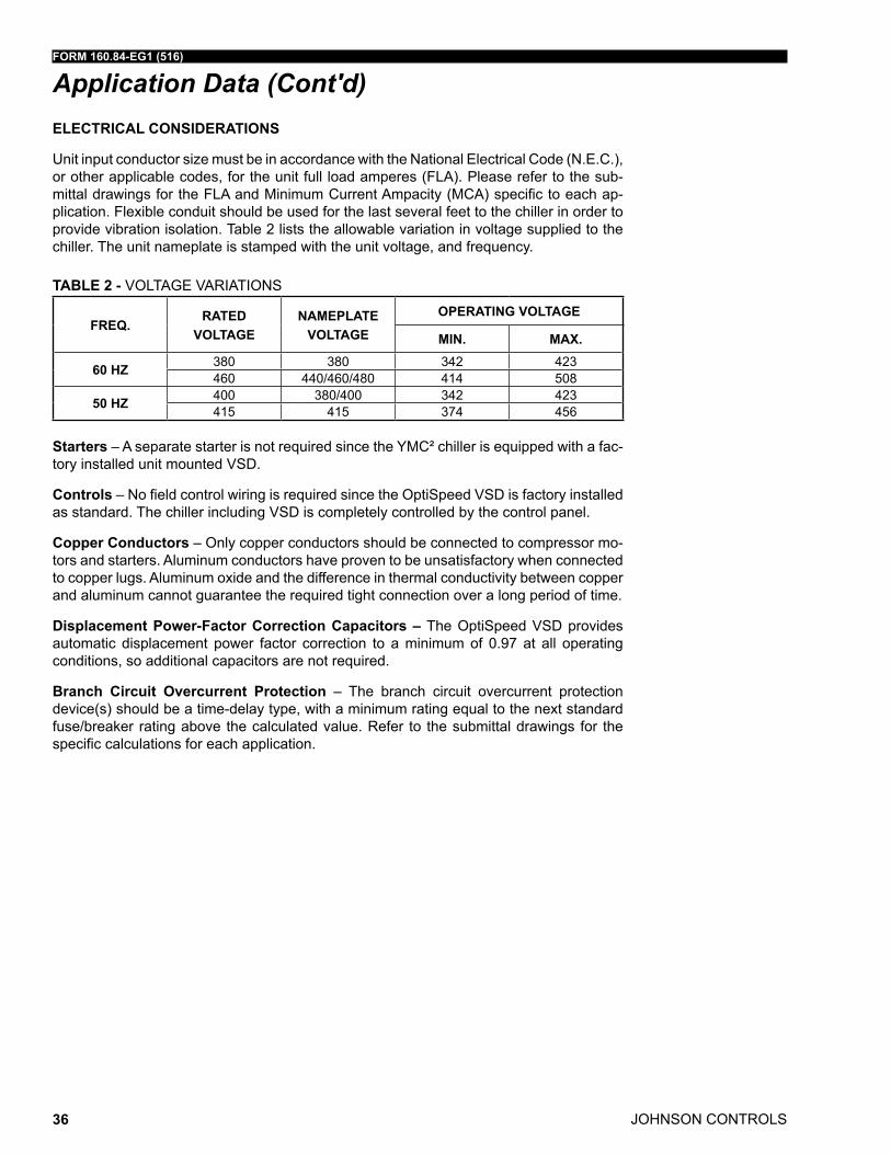
unit input conductor size must be in accordance with the national Electrical Code (n.E.C.), or other applicable codes, for the unit full load amperes (fla). Please refer to the sub-mittal drawings for the fla and minimum Current ampacity (mCa) specific to each ap-plication. flexible conduit should be used for the last several feet to the chiller in order to provide vibration isolation. table 2 lists the allowable variation in voltage supplied to the chiller. the unit nameplate is stamped with the unit voltage, and frequency.
TABLE 2 - VoltaGE Variations
FREq.RATED
VOLTAGENAMEPLATE
VOLTAGE
OPERATING VOLTAGE
MIN. MAX.
60 HZ 380 380 342 423460 440/460/480 414 508
50 HZ 400 380/400 342 423415 415 374 456
Starters – a separate starter is not required since the YmC² chiller is equipped with a fac-tory installed unit mounted Vsd.
Controls – no field control wiring is required since the optispeed Vsd is factory installed as standard. the chiller including Vsd is completely controlled by the control panel.
Copper Conductors – only copper conductors should be connected to compressor mo-tors and starters. aluminum conductors have proven to be unsatisfactory when connected to copper lugs. aluminum oxide and the difference in thermal conductivity between copper and aluminum cannot guarantee the required tight connection over a long period of time.
Displacement Power-Factor Correction Capacitors – the optispeed Vsd provides automatic displacement power factor correction to a minimum of 0.97 at all operating conditions, so additional capacitors are not required.
Branch Circuit Overcurrent Protection – the branch circuit overcurrent protection device(s) should be a time-delay type, with a minimum rating equal to the next standard fuse/breaker rating above the calculated value. refer to the submittal drawings for the specific calculations for each application.
Application Data (Cont'd)
FORM 160.84-EG1 (516)
JOHNSON CONTROLS 37
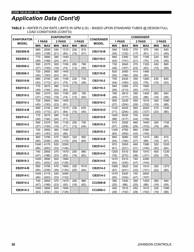
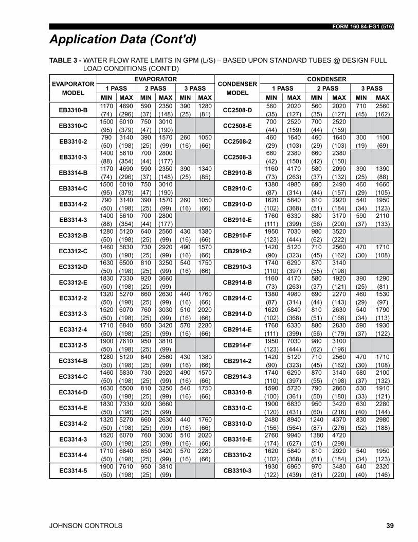
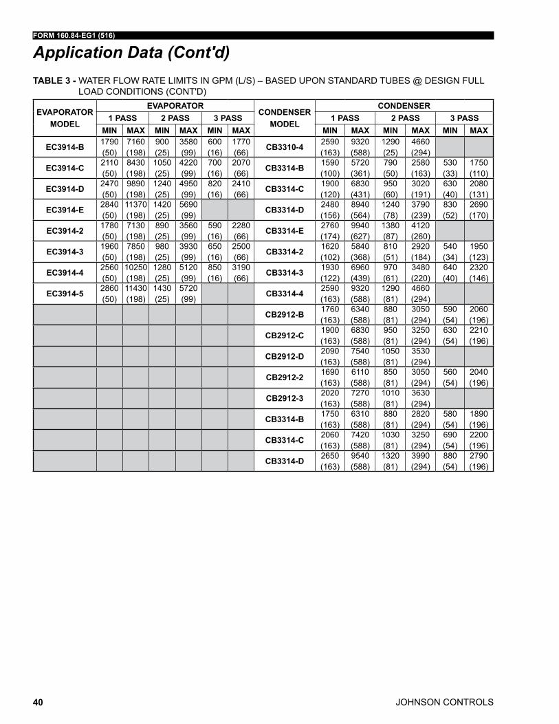
Application Data (Cont'd)TABLE 3 - WatEr floW ratE limits in GPm (l/s) – BasEd uPon standard tuBEs @ dEsiGn full
load Conditions
EVAPORATORMODEL
EVAPORATOR CONDENSER MODEL
CONDENSER1 PASS 2 PASS 3 PASS 1 PASS 2 PASS 3 PASS
MIN MAX MIN MAX MIN MAX MIN MAX MIN MAX MIN MAX
EA2508-C 740 (47)
2970 (187)
370 (23)
1410 (89)
250 (16)
880 (56)
CA2508-E 1400 (88)
5030 (317)
700 (44)
2520 (159)
470 (30)
1680 (106)
EA2510-B 630 (40)
2520 (159)
320 (20)
1110 (70)
210 (13)
700 (44)
CA2110-B 480 (30)
1730 (109)
240 (15)
860 (54)
160 (10)
580 (37)
EA2510-C 740 (47)
2970 (187)
370 (23)
1280 (81)
250 (16)
800 (50)
CA2110-C 780 (49)
2810 (177)
390 (25)
1400 (88)
260 (16)
940 (59)
EA2510-2 480 (30)
1910 (121)
240 (15)
950 (60)
160 (10)
640 (40)
CA2110-D 610 (38)
2200 (139)
310 (20)
1100 (69)
200 (13)
730 (46)
EA2510-3 660 (42)
2660 (168)
330 (21)
1330 (84)
220 (14)
890 (56)
CA2110-E 900 (57)
3230 (204)
450 (28)
1610 (102)
EA2514-B 630 (40)
2520 (159)
320 (20)
940 (59)
210 (13)
600 (38)
CA2110-2 680 (43)
2450 (155)
340 (21)
1230 (78)
230 (15)
820 (52)
EA2514-C 740 (47)
2970 (187)
370 (23)
1090 (69)
250 (16)
690 (44)
CA2110-3 1120 (71)
4030 (254)
560 (35)
2020 (127)
EA2514-2 480 (30)
1910 (121)
240 (15)
930 (59)
160 (10)
600 (38)
CA2510-B 770 (49)
2770 (175)
380 (24)
1390 (88)
260 (16)
920 (58)
EA2514-3 660 (42)
2660 (168)
330 (21)
1250 (79)
220 (14)
790 (50)
CA2510-C 1400 (88)
5030 (317)
700 (44)
2520 (159)
470 (30)
1680 (106)
CA2510-D 600 (38)
2170 (137)
300 (19)
1080 (68)
200 (13)
720 (45)
CA2510-E 840 (53)
3020 (191)
420 (26)
1510 (95)
CA2510-2 910 (57)
3290 (208)
460 (29)
1640 (103)
300 (19)
1100 (69)
CA2510-3 1320 (83)
4760 (300)
660 (42)
2380 (150)
CA2514-B 780 (49)
2810 (177)
390 (25)
1290 (81)
260 (16)
850 (54)
CA2514-C 900 (57)
3230 (204)
450 (28)
1470 (93)
300 (19)
970 (61)
CA2514-D 1120 (71)
4030 (254)
560 (35)
1800 (114)
370 (23)
1190 (75)
CA2514-E 1400 (88)
5030 (317)
700 (44)
2180 (138)
CA2514-2 910 (57)
3290 (208)
460 (29)
1640 (103)
300 (19)
1100 (69)
CA2514-3 1320 (83)
4760 (300)
660 (42)
2380 (150)
JOHNSON CONTROLS
FORM 160.84-EG1 (516)
38
EVAPORATORMODEL
EVAPORATORCONDENSER
MODEL
CONDENSER1 PASS 2 PASS 3 PASS 1 PASS 2 PASS 3 PASS
MIN MAX MIN MAX MIN MAX MIN MAX MIN MAX MIN MAX
EB2508-B 680 (43)
2500 (158)
340 (21)
1310 (83)
230 (15)
810 (51)
CB2110-B 540 (34)
1930 (122)
270 (17)
970 (61)
180 (11)
640 (40)
EB2508-C 770 (49)
2680 (169)
380 (24)
1440 (91)
CB2110-C 660 (42)
2390 (151)
330 (21)
1190 (75)
220 (14)
800 (50)
EB2508-2 590 (37)
2370 (150)
300 (19)
1180 (74)
200 (13)
790 (50)
CB2110-D 730 (46)
2640 (167)
370 (23)
1320 (83)
240 (15)
880 (56)
EB2508-3 720 (45)
2900 (183)
360 (23)
1450 (91)
CB2110-E 820 (52)
2950 (186)
410 (26)
1480 (93)
EB2510-B 680 (43)
2740 (173)
340 (21)
1190 (75)
230 (15)
730 (46)
CB2110-2 700 (44)
2530 (160)
350 (22)
1260 (79)
230 (15)
840 (53)
EB2510-C 770 (49)
3070 (194)
380 (24)
1310 (83)
CB2110-3 940 (59)
3380 (213)
470 (30)
1690 (107)
EB2510-2 590 (37)
2370 (150)
300 (19)
1180 (74)
200 (13)
790 (50)
CB2510-B 780 (49)
2810 (177)
390 (25)
1400 (88)
260 (16)
940 (59)
EB2510-3 720 (45)
2900 (183)
360 (23)
1450 (91)
CB2510-C 900 (57)
3230 (204)
450 (28)
1610 (102)
300 (19)
1080 (68)
EB2514-B 680 (43)
2740 (173)
340 (21)
1010 (64)
230 (15)
630 (40)
CB2510-D 1120 (71)
4030 (254)
560 (35)
2020 (127)
370 (23)
1340 (85)
EB2514-C 770 (49)
3070 (194)
380 (24)
1120 (71)
CB2510-E 1400 (88)
5030 (317)
700 (44)
2520 (159)
EB2514-2 590 (37)
2370 (150)
300 (19)
1130 (71)
200 (13)
700 (44)
CB2510-2 910 (57)
3290 (208)
460 (29)
1640 (103)
300 (19)
1100 (69)
EB2514-3 720 (45)
2900 (183)
360 (23)
1340 (85)
CB2510-3 1320 (83)
4760 (300)
660 (42)
2380 (150)
EB2910-B 950 (60)
3790 (239)
470 (30)
1820 (115)
320 (20)
950 (60)
CB2514-B 850 (54)
3080 (194)
430 (27)
1410 (89)
280 (18)
910 (57)
EB2910-C 1040 (66)
4170 (263)
520 (33)
2000 (126)
CB2514-C 970 (61)
3500 (221)
490 (31)
1580 (100)
320 (20)
1020 (64)
EB2910-2 740 (47)
2950 (186)
370 (23)
1470 (93)
250 (16)
980 (62)
CB2514-D 1200 (76)
4310 (272)
600 (38)
1910 (121)
400 (25)
1230 (78)
EB2910-3 1000 (63)
3990 (252)
500 (32)
1990 (126)
CB2514-E 1470 (93)
5310 (335)
740 (47)
2280 (144)
EB2914-B 950 (60)
3790 (239)
470 (30)
1900 (120)
320 (20)
1010 (64)
CB2514-2 1060 (67)
3820 (241)
530 (33)
1910 (121)
350 (22)
1270 (80)
EB2914-C 1040 (66)
4170 (263)
520 (33)
2090 (132)
CB2514-3 1470 (93)
5300 (334)
740 (47)
2650 (167)
EB2914-2 740 (47)
2950 (186)
370 (23)
1470 (93)
250 (16)
980 (62)
CC2508-B 390 (25)
1400 (88)
390 (25)
1400 (88)
260 (16)
940 (59)
EB2914-3 1000 (63)
3990 (252)
500 (32)
1990 (126)
CC2508-C 450 (28)
1610 (102)
450 (28)
1610 (102)
300 (19)
1080 (68)
Application Data (Cont'd)TABLE 3 - WatEr floW ratE limits in GPm (l/s) – BasEd uPon standard tuBEs @ dEsiGn full
load Conditions (Cont'd)
FORM 160.84-EG1 (516)
JOHNSON CONTROLS 39
EVAPORATORMODEL
EVAPORATORCONDENSER
MODEL
CONDENSER1 PASS 2 PASS 3 PASS 1 PASS 2 PASS 3 PASS
MIN MAX MIN MAX MIN MAX MIN MAX MIN MAX MIN MAX
EB3310-B 1170 (74)
4690 (296)
590 (37)
2350 (148)
390 (25)
1280 (81)
CC2508-D 560 (35)
2020 (127)
560 (35)
2020 (127)
710 (45)
2560 (162)
EB3310-C 1500 (95)
6010 (379)
750 (47)
3010 (190)
CC2508-E 700 (44)
2520 (159)
700 (44)
2520 (159)
EB3310-2 790 (50)
3140 (198)
390 (25)
1570 (99)
260 (16)
1050 (66)
CC2508-2 460 (29)
1640 (103)
460 (29)
1640 (103)
300 (19)
1100 (69)
EB3310-3 1400 (88)
5610 (354)
700 (44)
2800 (177)
CC2508-3 660 (42)
2380 (150)
660 (42)
2380 (150)
EB3314-B 1170 (74)
4690 (296)
590 (37)
2350 (148)
390 (25)
1340 (85)
CB2910-B 1160 (73)
4170 (263)
580 (37)
2090 (132)
390 (25)
1390 (88)
EB3314-C 1500 (95)
6010 (379)
750 (47)
3010 (190)
CB2910-C 1380 (87)
4980 (314)
690 (44)
2490 (157)
460 (29)
1660 (105)
EB3314-2 790 (50)
3140 (198)
390 (25)
1570 (99)
260 (16)
1050 (66)
CB2910-D 1620 (102)
5840 (368)
810 (51)
2920 (184)
540 (34)
1950 (123)
EB3314-3 1400 (88)
5610 (354)
700 (44)
2800 (177)
CB2910-E 1760 (111)
6330 (399)
880 (56)
3170 (200)
590 (37)
2110 (133)
EC3312-B 1280 (50)
5120 (198)
640 (25)
2560 (99)
430 (16)
1380 (66)
CB2910-F 1950 (123)
7030 (444)
980 (62)
3520 (222)
EC3312-C 1460 (50)
5830 (198)
730 (25)
2920 (99)
490 (16)
1570 (66)
CB2910-2 1420 (90)
5120 (323)
710 (45)
2560 (162)
470 (30)
1710 (108)
EC3312-D 1630 (50)
6500 (198)
810 (25)
3250 (99)
540 (16)
1750 (66)
CB2910-3 1740 (110)
6290 (397)
870 (55)
3140 (198)
EC3312-E 1830 (50)
7330 (198)
920 (25)
3660 (99)
CB2914-B 1160 (73)
4170 (263)
580 (37)
1920 (121)
390 (25)
1290 (81)
EC3312-2 1320 (50)
5270 (198)
660 (25)
2630 (99)
440 (16)
1760 (66)
CB2914-C 1380 (87)
4980 (314)
690 (44)
2270 (143)
460 (29)
1530 (97)
EC3312-3 1520 (50)
6070 (198)
760 (25)
3030 (99)
510 (16)
2020 (66)
CB2914-D 1620 (102)
5840 (368)
810 (51)
2630 (166)
540 (34)
1790 (113)
EC3312-4 1710 (50)
6840 (198)
850 (25)
3420 (99)
570 (16)
2280 (66)
CB2914-E 1760 (111)
6330 (399)
880 (56)
2830 (179)
590 (37)
1930 (122)
EC3312-5 1900 (50)
7610 (198)
950 (25)
3810 (99)
CB2914-F 1950 (123)
7030 (444)
980 (62)
3100 (196)
EC3314-B 1280 (50)
5120 (198)
640 (25)
2560 (99)
430 (16)
1380 (66)
CB2914-2 1420 (90)
5120 (323)
710 (45)
2560 (162)
470 (30)
1710 (108)
EC3314-C 1460 (50)
5830 (198)
730 (25)
2920 (99)
490 (16)
1570 (66)
CB2914-3 1740 (110)
6290 (397)
870 (55)
3140 (198)
580 (37)
2100 (132)
EC3314-D 1630 (50)
6500 (198)
810 (25)
3250 (99)
540 (16)
1750 (66)
CB3310-B 1590 (100)
5720 (361)
790 (50)
2860 (180)
530 (33)
1910 (121)
EC3314-E 1830 (50)
7330 (198)
920 (25)
3660 (99)
CB3310-C 1900 (120)
6830 (431)
950 (60)
3420 (216)
630 (40)
2280 (144)
EC3314-2 1320 (50)
5270 (198)
660 (25)
2630 (99)
440 (16)
1760 (66)
CB3310-D 2480 (156)
8940 (564)
1240 (87)
4370 (276)
830 (52)
2980 (188)
EC3314-3 1520 (50)
6070 (198)
760 (25)
3030 (99)
510 (16)
2020 (66)
CB3310-E 2760 (174)
9940 (627)
1380 (51)
4720 (298)
EC3314-4 1710 (50)
6840 (198)
850 (25)
3420 (99)
570 (16)
2280 (66)
CB3310-2 1620 (102)
5840 (368)
810 (61)
2920 (184)
540 (34)
1950 (123)
EC3314-5 1900 (50)
7610 (198)
950 (25)
3810 (99)
CB3310-3 1930 (122)
6960 (439)
970 (81)
3480 (220)
640 (40)
2320 (146)
Application Data (Cont'd)TABLE 3 - WatEr floW ratE limits in GPm (l/s) – BasEd uPon standard tuBEs @ dEsiGn full
load Conditions (Cont'd)
JOHNSON CONTROLS
FORM 160.84-EG1 (516)
40
EVAPORATORMODEL
EVAPORATORCONDENSER
MODEL
CONDENSER1 PASS 2 PASS 3 PASS 1 PASS 2 PASS 3 PASS
MIN MAX MIN MAX MIN MAX MIN MAX MIN MAX MIN MAX
EC3914-B 1790 (50)
7160 (198)
900 (25)
3580 (99)
600 (16)
1770 (66)
CB3310-4 2590 (163)
9320 (588)
1290 (25)
4660 (294)
EC3914-C 2110 (50)
8430 (198)
1050 (25)
4220 (99)
700 (16)
2070 (66)
CB3314-B 1590 (100)
5720 (361)
790 (50)
2580 (163)
530 (33)
1750 (110)
EC3914-D 2470 (50)
9890 (198)
1240 (25)
4950 (99)
820 (16)
2410 (66)
CB3314-C 1900 (120)
6830 (431)
950 (60)
3020 (191)
630 (40)
2080 (131)
EC3914-E 2840 (50)
11370 (198)
1420 (25)
5690 (99)
CB3314-D 2480 (156)
8940 (564)
1240 (78)
3790 (239)
830 (52)
2690 (170)
EC3914-2 1780 (50)
7130 (198)
890 (25)
3560 (99)
590 (16)
2280 (66)
CB3314-E 2760 (174)
9940 (627)
1380 (87)
4120 (260)
EC3914-3 1960 (50)
7850 (198)
980 (25)
3930 (99)
650 (16)
2500 (66)
CB3314-2 1620 (102)
5840 (368)
810 (51)
2920 (184)
540 (34)
1950 (123)
EC3914-4 2560 (50)
10250 (198)
1280 (25)
5120 (99)
850 (16)
3190 (66)
CB3314-3 1930 (122)
6960 (439)
970 (61)
3480 (220)
640 (40)
2320 (146)
EC3914-5 2860 (50)
11430 (198)
1430 (25)
5720 (99)
CB3314-4 2590 (163)
9320 (588)
1290 (81)
4660 (294)
CB2912-B 1760 (163)
6340 (588)
880 (81)
3050 (294)
590 (54)
2060 (196)
CB2912-C 1900 (163)
6830 (588)
950 (81)
3250 (294)
630 (54)
2210 (196)
CB2912-D 2090 (163)
7540 (588)
1050 (81)
3530 (294)
CB2912-2 1690 (163)
6110 (588)
850 (81)
3050 (294)
560 (54)
2040 (196)
CB2912-3 2020 (163)
7270 (588)
1010 (81)
3630 (294)
CB3314-B 1750 (163)
6310 (588)
880 (81)
2820 (294)
580 (54)
1890 (196)
CB3314-C 2060 (163)
7420 (588)
1030 (81)
3250 (294)
690 (54)
2200 (196)
CB3314-D 2650 (163)
9540 (588)
1320 (81)
3990 (294)
880 (54)
2790 (196)
Application Data (Cont'd)TABLE 3 - WatEr floW ratE limits in GPm (l/s) – BasEd uPon standard tuBEs @ dEsiGn full
load Conditions (Cont'd)
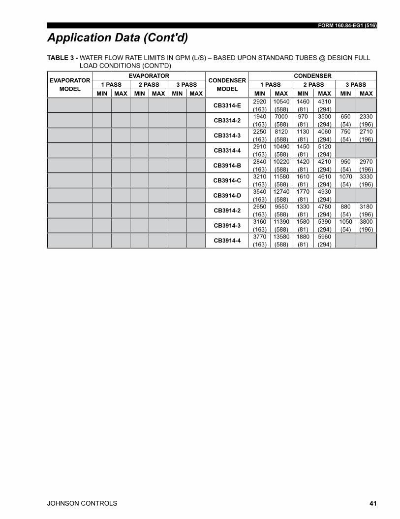
FORM 160.84-EG1 (516)
JOHNSON CONTROLS 41
Application Data (Cont'd)
EVAPORATORMODEL
EVAPORATORCONDENSER
MODEL
CONDENSER1 PASS 2 PASS 3 PASS 1 PASS 2 PASS 3 PASS
MIN MAX MIN MAX MIN MAX MIN MAX MIN MAX MIN MAX
CB3314-E 2920 (163)
10540 (588)
1460 (81)
4310 (294)
CB3314-2 1940 (163)
7000 (588)
970 (81)
3500 (294)
650 (54)
2330 (196)
CB3314-3 2250 (163)
8120 (588)
1130 (81)
4060 (294)
750 (54)
2710 (196)
CB3314-4 2910 (163)
10490 (588)
1450 (81)
5120 (294)
CB3914-B 2840 (163)
10220 (588)
1420 (81)
4210 (294)
950 (54)
2970 (196)
CB3914-C 3210 (163)
11580 (588)
1610 (81)
4610 (294)
1070 (54)
3330 (196)
CB3914-D 3540 (163)
12740 (588)
1770 (81)
4930 (294)
CB3914-2 2650 (163)
9550 (588)
1330 (81)
4780 (294)
880 (54)
3180 (196)
CB3914-3 3160 (163)
11390 (588)
1580 (81)
5390 (294)
1050 (54)
3800 (196)
CB3914-4 3770 (163)
13580 (588)
1880 (81)
5960 (294)
TABLE 3 - WatEr floW ratE limits in GPm (l/s) – BasEd uPon standard tuBEs @ dEsiGn full load Conditions (Cont'd)
JOHNSON CONTROLS
FORM 160.84-EG1 (516)
42
1. the following notes apply to the dimension drawings on pages 41 through 67.
2. Alldimensionsareapproximate.Certifieddimensionsareavailableonrequest.
3. the standard water nozzles are schedule 40 pipe size, furnished as welding stub-outswithANSI/AWWAC-606grooves,allowingtheoptionofwelding,flanges,oruse of ansi/aWWa C-606 couplings. factory-installed, class 150 (ansi B16.5, roundslip-onforgedcarbonsteelwith1/16"raisedface),waterflangednozzlesareoptional(add1/2"tonozzlelength).Companionflanges,nuts,bolts,andgasketsare not furnished.
4. one, two, and three-pass nozzle arrangements are available only in pairs shown for all shell codes. any pair of evaporator nozzles many be used in combination with any pair of condenser nozzles compact water boxes on one heat exchanger may be used with marine water Boxes on the other heat exchangers.
5. Condenser water must enter the water box through the bottom connection for prop-er operation of the sub-cooler to achieve rated performance.
6. to determine overall height, add dimension "m" for the appropriate isolator type.
7. standard 150 Psi design pressure boxes shown.
Unit Dimensions
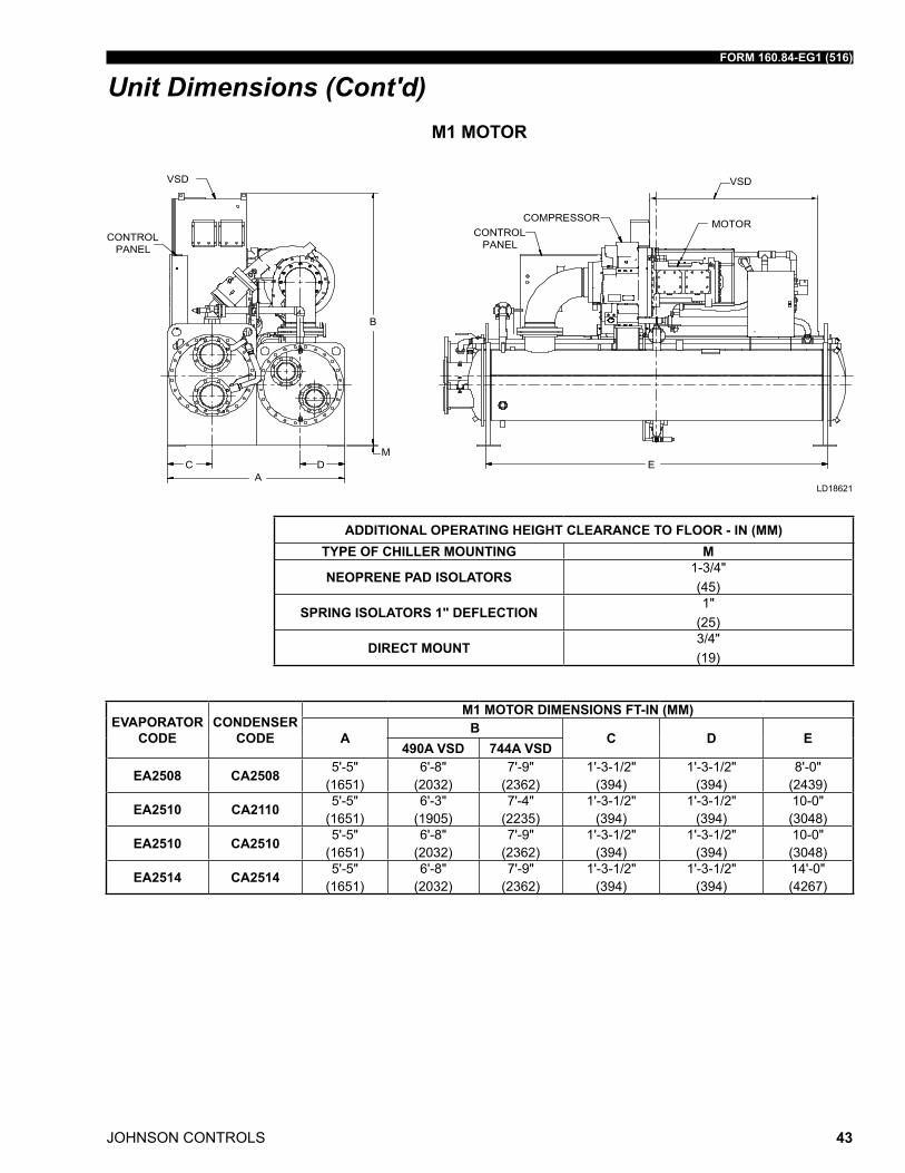
FORM 160.84-EG1 (516)
JOHNSON CONTROLS 43
EVAPORATOR CODE
CONDENSER CODE
M1 MOTOR DIMENSIONS FT-IN (MM)
AB
C D E490A VSD 744A VSD
EA2508 CA2508 5'-5" (1651)
6'-8" (2032)
7'-9" (2362)
1'-3-1/2" (394)
1'-3-1/2" (394)
8'-0" (2439)
EA2510 CA2110 5'-5" (1651)
6'-3" (1905)
7'-4" (2235)
1'-3-1/2" (394)
1'-3-1/2" (394)
10-0" (3048)
EA2510 CA2510 5'-5" (1651)
6'-8" (2032)
7'-9" (2362)
1'-3-1/2" (394)
1'-3-1/2" (394)
10-0" (3048)
EA2514 CA2514 5'-5" (1651)
6'-8" (2032)
7'-9" (2362)
1'-3-1/2" (394)
1'-3-1/2" (394)
14'-0" (4267)
Unit Dimensions (Cont'd)
ADDITIONAL OPERATING HEIGHT CLEARANCE TO FLOOR - IN (MM)TyPE OF CHILLER MOUNTING M
NEOPRENE PAD ISOLATORS1-3/4"(45)
SPRING ISOLATORS 1" DEFLECTION1"
(25)
DIRECT MOUNT3/4"(19)
M1 MOTOR
ld18621
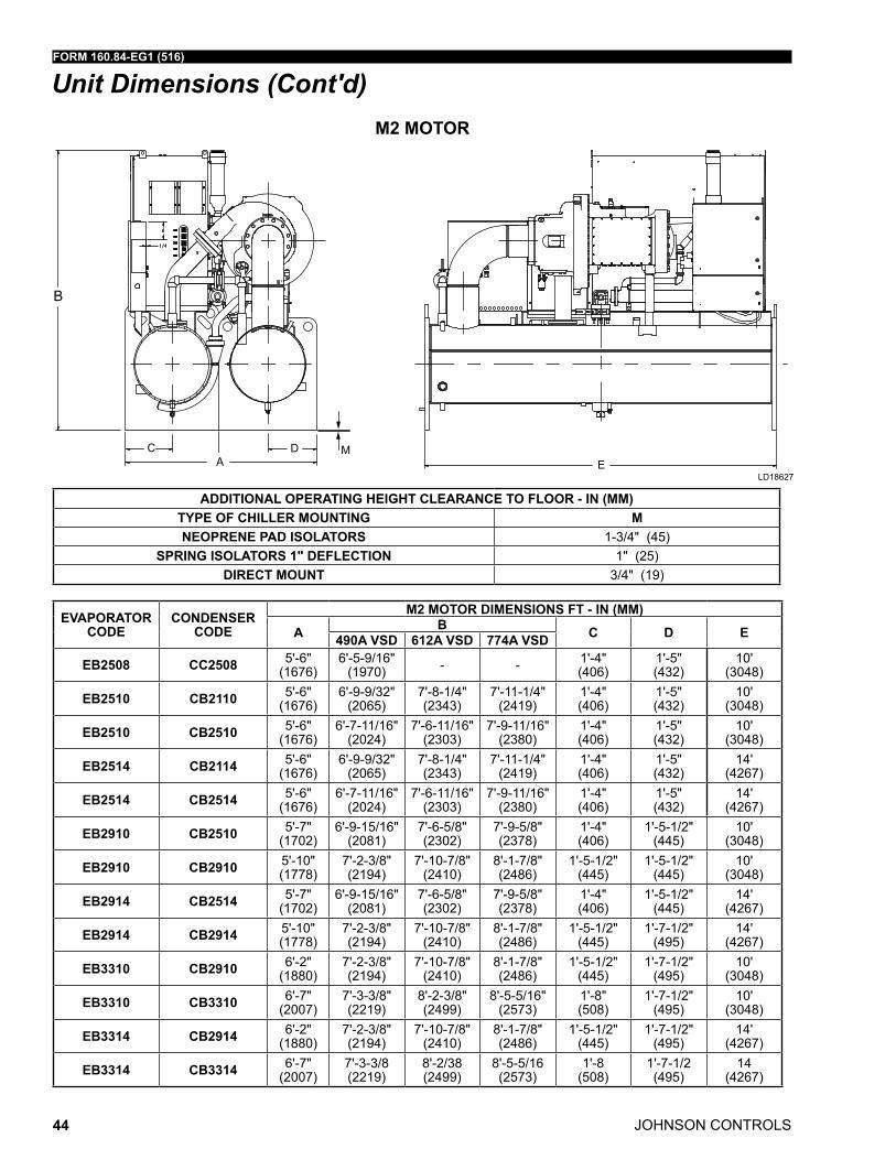
JOHNSON CONTROLS
FORM 160.84-EG1 (516)
44
Unit Dimensions (Cont'd)
B
C D MA E
EVAPORATOR CODE
CONDENSER CODE
M2 MOTOR DIMENSIONS FT - IN (MM)
A B C D E490A VSD 612A VSD 774A VSD
EB2508 CC2508 5'-6" (1676)
6'-5-9/16" (1970) - - 1'-4"
(406)1'-5" (432)
10' (3048)
EB2510 CB2110 5'-6" (1676)
6'-9-9/32" (2065)
7'-8-1/4" (2343)
7'-11-1/4" (2419)
1'-4" (406)
1'-5" (432)
10' (3048)
EB2510 CB2510 5'-6" (1676)
6'-7-11/16" (2024)
7'-6-11/16" (2303)
7'-9-11/16" (2380)
1'-4" (406)
1'-5" (432)
10' (3048)
EB2514 CB2114 5'-6" (1676)
6'-9-9/32" (2065)
7'-8-1/4" (2343)
7'-11-1/4" (2419)
1'-4" (406)
1'-5" (432)
14' (4267)
EB2514 CB2514 5'-6" (1676)
6'-7-11/16" (2024)
7'-6-11/16" (2303)
7'-9-11/16" (2380)
1'-4" (406)
1'-5" (432)
14' (4267)
EB2910 CB2510 5'-7" (1702)
6'-9-15/16" (2081)
7'-6-5/8" (2302)
7'-9-5/8" (2378)
1'-4" (406)
1'-5-1/2" (445)
10' (3048)
EB2910 CB2910 5'-10" (1778)
7'-2-3/8" (2194)
7'-10-7/8" (2410)
8'-1-7/8" (2486)
1'-5-1/2" (445)
1'-5-1/2" (445)
10' (3048)
EB2914 CB2514 5'-7" (1702)
6'-9-15/16" (2081)
7'-6-5/8" (2302)
7'-9-5/8" (2378)
1'-4" (406)
1'-5-1/2" (445)
14' (4267)
EB2914 CB2914 5'-10" (1778)
7'-2-3/8" (2194)
7'-10-7/8" (2410)
8'-1-7/8" (2486)
1'-5-1/2" (445)
1'-7-1/2" (495)
14' (4267)
EB3310 CB2910 6'-2" (1880)
7'-2-3/8" (2194)
7'-10-7/8" (2410)
8'-1-7/8" (2486)
1'-5-1/2" (445)
1'-7-1/2" (495)
10' (3048)
EB3310 CB3310 6'-7" (2007)
7'-3-3/8" (2219)
8'-2-3/8" (2499)
8'-5-5/16" (2573)
1'-8" (508)
1'-7-1/2" (495)
10' (3048)
EB3314 CB2914 6'-2" (1880)
7'-2-3/8" (2194)
7'-10-7/8" (2410)
8'-1-7/8" (2486)
1'-5-1/2" (445)
1'-7-1/2" (495)
14' (4267)
EB3314 CB3314 6'-7" (2007)
7'-3-3/8 (2219)
8'-2/38 (2499)
8'-5-5/16 (2573)
1'-8 (508)
1'-7-1/2 (495)
14 (4267)
M2 MOTOR
ADDITIONAL OPERATING HEIGHT CLEARANCE TO FLOOR - IN (MM)TyPE OF CHILLER MOUNTING MNEOPRENE PAD ISOLATORS 1-3/4" (45)
SPRING ISOLATORS 1" DEFLECTION 1" (25)DIRECT MOUNT 3/4" (19)
ld18627
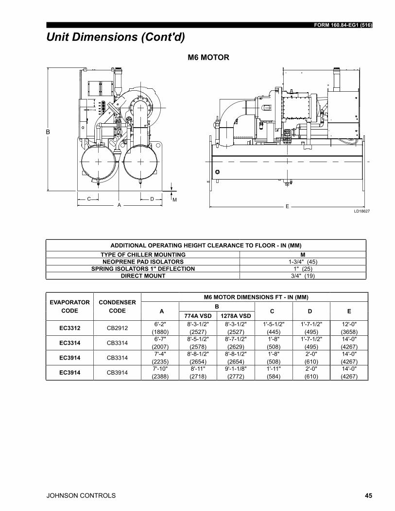
FORM 160.84-EG1 (516)
JOHNSON CONTROLS 45
Unit Dimensions (Cont'd)
B
C D MA E
M6 MOTOR
ADDITIONAL OPERATING HEIGHT CLEARANCE TO FLOOR - IN (MM)TyPE OF CHILLER MOUNTING MNEOPRENE PAD ISOLATORS 1-3/4" (45)
SPRING ISOLATORS 1" DEFLECTION 1" (25)DIRECT MOUNT 3/4" (19)
ld18627
EVAPORATORCODE
CONDENSERCODE
M6 MOTOR DIMENSIONS FT - IN (MM)
AB
C D E774A VSD 1278A VSD
EC3312 CB29126'-2"
(1880)8'-3-1/2" (2527)
8'-3-1/2" (2527)
1'-5-1/2" (445)
1'-7-1/2" (495)
12'-0" (3658)
EC3314 CB33146'-7"
(2007)8'-5-1/2" (2578)
8'-7-1/2" (2629)
1'-8" (508)
1'-7-1/2" (495)
14'-0" (4267)
EC3914 CB33147'-4"
(2235)8'-8-1/2" (2654)
8'-8-1/2" (2654)
1'-8" (508)
2'-0" (610)
14'-0" (4267)
EC3914 CB39147'-10" (2388)
8'-11" (2718)
9'-1-1/8" (2772)
1'-11" (584)
2'-0" (610)
14'-0" (4267)
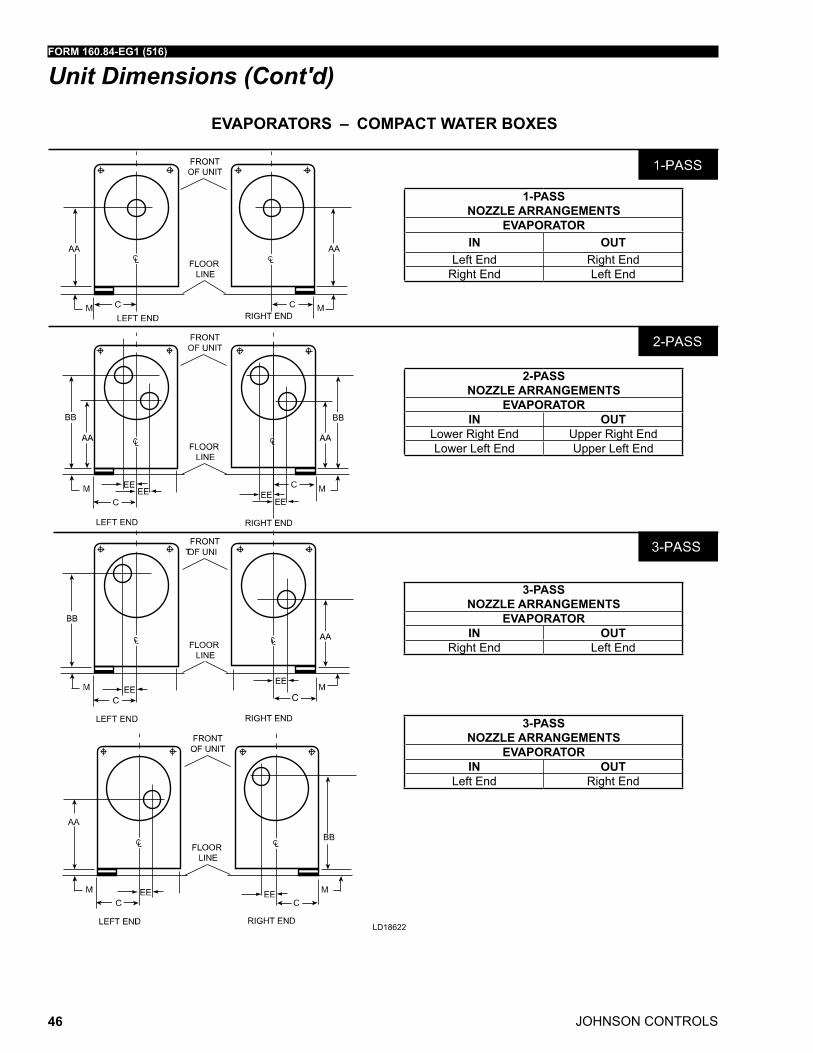
JOHNSON CONTROLS
FORM 160.84-EG1 (516)
46
LD18622
EVAPORATORS – COMPACT WATER BOXES
1-PASS NOZZLE ARRANGEMENTS
EVAPORATORIN OUT
left End right Endright End left End
2-PASS NOZZLE ARRANGEMENTS
EVAPORATORIN OUT
lower right End upper right Endlower left End upper left End
3-PASS NOZZLE ARRANGEMENTS
EVAPORATORIN OUT
right End left End
3-PASS NOZZLE ARRANGEMENTS
EVAPORATORIN OUT
left End right End
Unit Dimensions (Cont'd)
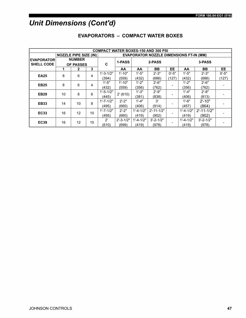
FORM 160.84-EG1 (516)
JOHNSON CONTROLS 47
COMPACT WATER BOXES-150 AND 300 PSI
EVAPORATOR SHELL CODE
NOZZLE PIPE SIZE (IN) EVAPORATOR NOZZLE DIMENSIONS FT-IN (MM)NUMBER
OF PASSES C 1-PASS 2-PASS 3-PASS
1 2 3 AA AA BB EE AA BB EE
EA25 8 6 41'-3-1/2"
(394)1'-10" (559)
1'-5" (432)
2'-3" (686)
0'-5" (127)
1'-5" (432)
2'-3" (686)
0'-5" (127)
EB25 8 6 41'-5" (432)
1'-10" (559)
1'-2" (356)
2'-6" (762)
-1'-2" (356)
2'-6" (762)
-
EB29 10 8 61'-5-1/2"
(445)2' (610)
1'-3" (381)
2'-9" (838)
-1'-4" (406)
2'-8" (813)
-
EB33 14 10 81'-7-1/2"
(495)2'-2" (660)
1'-4" (406)
3' (914)
-1'-6" (457)
2'-10" (864) -
EC33 16 12 101'-7-1/2"
(495)2'-2" (660)
1'-4-1/2" (419)
2'-11-1/2" (902)
-1'-4-1/2"
(419)2'-11-1/2"
(902) -
EC39 16 12 102'
(610)2'-3-1/2"
(699)1'-4-1/2"
(419)3'-2-1/2"
(978)-
1'-4-1/2" (419)
3'-2-1/2" (978)
-
Unit Dimensions (Cont'd)EVAPORATORS – COMPACT WATER BOXES
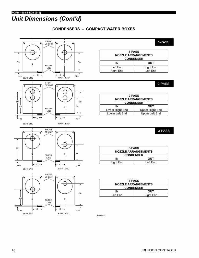
JOHNSON CONTROLS
FORM 160.84-EG1 (516)
48
CONDENSERS – COMPACT WATER BOXES
Unit Dimensions (Cont'd)
ld18623
1-PASS NOZZLE ARRANGEMENTS
CONDENSERIN OUT
left End right Endright End left End
2-PASS NOZZLE ARRANGEMENTS
CONDENSERIN OUT
lower right End upper right Endlower left End upper left End
3-PASS NOZZLE ARRANGEMENTS
CONDENSERIN OUT
right End left End
3-PASS NOZZLE ARRANGEMENTS
CONDENSERIN OUT
left End right End
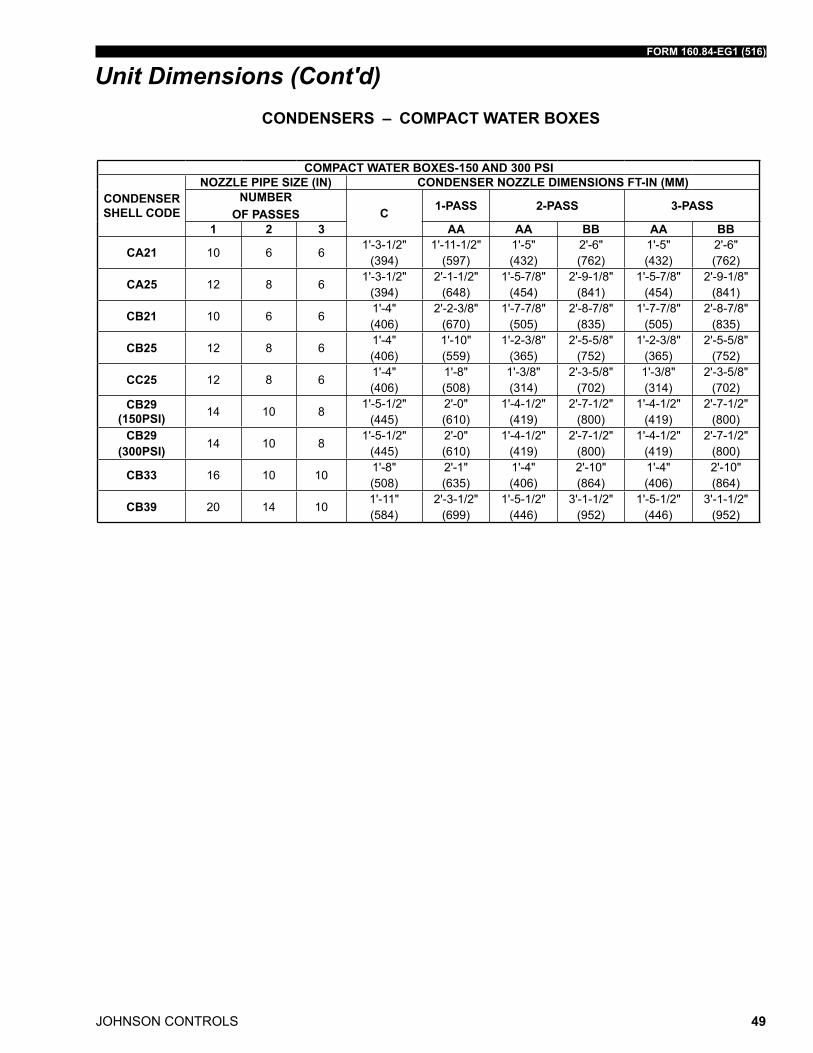
FORM 160.84-EG1 (516)
JOHNSON CONTROLS 49
COMPACT WATER BOXES-150 AND 300 PSI
CONDENSER SHELL CODE
NOZZLE PIPE SIZE (IN) CONDENSER NOZZLE DIMENSIONS FT-IN (MM)NUMBER
OF PASSES C 1-PASS 2-PASS 3-PASS
1 2 3 AA AA BB AA BB
CA21 10 6 61'-3-1/2"
(394)1'-11-1/2"
(597)1'-5" (432)
2'-6" (762)
1'-5" (432)
2'-6" (762)
CA25 12 8 61'-3-1/2"
(394)2'-1-1/2"
(648)1'-5-7/8"
(454)2'-9-1/8"
(841)1'-5-7/8"
(454)2'-9-1/8"
(841)
CB21 10 6 61'-4" (406)
2'-2-3/8" (670)
1'-7-7/8" (505)
2'-8-7/8" (835)
1'-7-7/8" (505)
2'-8-7/8" (835)
CB25 12 8 61'-4" (406)
1'-10" (559)
1'-2-3/8" (365)
2'-5-5/8" (752)
1'-2-3/8" (365)
2'-5-5/8" (752)
CC25 12 8 61'-4" (406)
1'-8" (508)
1'-3/8" (314)
2'-3-5/8" (702)
1'-3/8" (314)
2'-3-5/8" (702)
CB29 (150PSI) 14 10 8
1'-5-1/2" (445)
2'-0" (610)
1'-4-1/2" (419)
2'-7-1/2" (800)
1'-4-1/2" (419)
2'-7-1/2" (800)
CB29 (300PSI) 14 10 8
1'-5-1/2" (445)
2'-0" (610)
1'-4-1/2" (419)
2'-7-1/2" (800)
1'-4-1/2" (419)
2'-7-1/2" (800)
CB33 16 10 101'-8" (508)
2'-1" (635)
1'-4" (406)
2'-10" (864)
1'-4" (406)
2'-10" (864)
CB39 20 14 101'-11" (584)
2'-3-1/2" (699)
1'-5-1/2" (446)
3'-1-1/2" (952)
1'-5-1/2" (446)
3'-1-1/2" (952)
CONDENSERS – COMPACT WATER BOXES
Unit Dimensions (Cont'd)
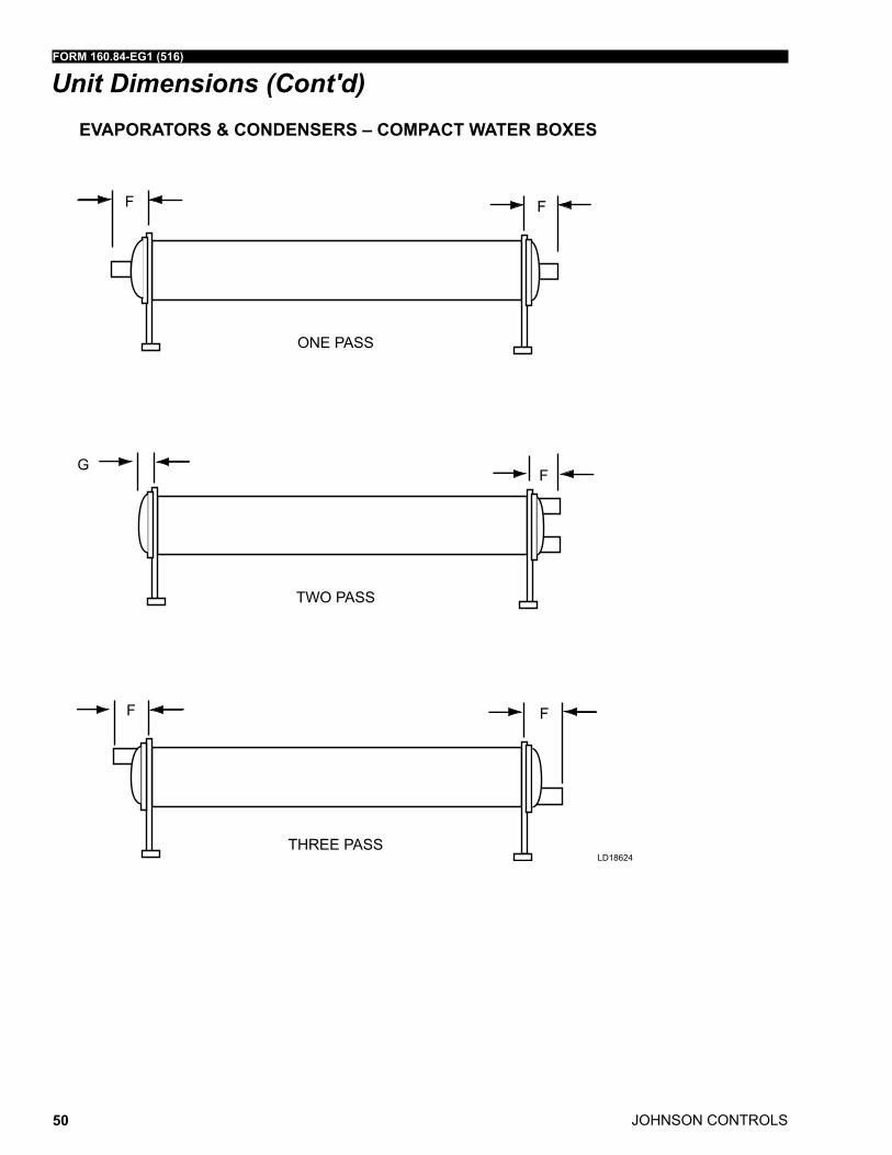
JOHNSON CONTROLS
FORM 160.84-EG1 (516)
50
Unit Dimensions (Cont'd)
F F
F F
FG
ONE PASS
TWO PASS
THREE PASS
EVAPORATORS & CONDENSERS – COMPACT WATER BOXES
ld18624
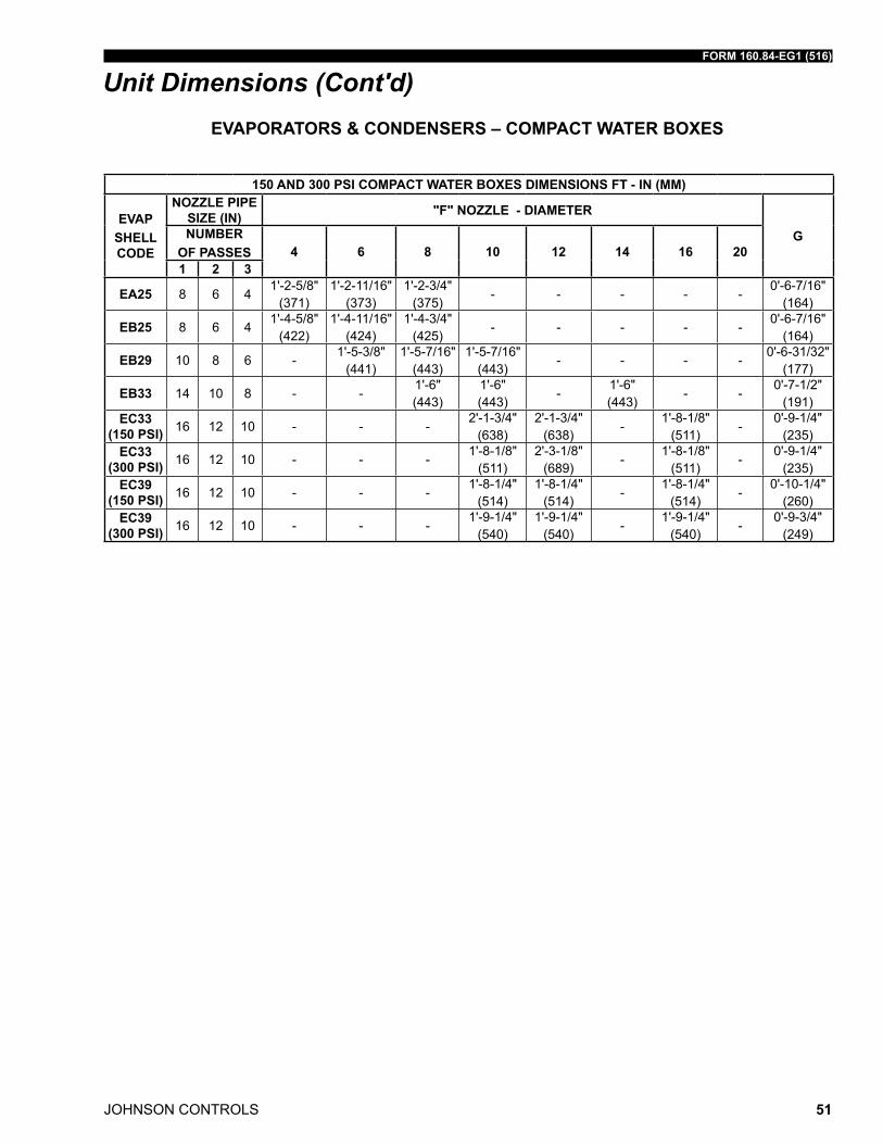
FORM 160.84-EG1 (516)
JOHNSON CONTROLS 51
Unit Dimensions (Cont'd)
150 AND 300 PSI COMPACT WATER BOXES DIMENSIONS FT - IN (MM)
EVAPSHELL CODE
NOZZLE PIPE SIZE (IN) "F" NOZZLE - DIAMETER
GNUMBER OF PASSES 4 6 8 10 12 14 16 201 2 3
EA25 8 6 41'-2-5/8"
(371)1'-2-11/16"
(373)1'-2-3/4"
(375)- - - - -
0'-6-7/16" (164)
EB25 8 6 41'-4-5/8"
(422)1'-4-11/16"
(424)1'-4-3/4"
(425)- - - - -
0'-6-7/16" (164)
EB29 10 8 6 -1'-5-3/8"
(441)1'-5-7/16"
(443)1'-5-7/16"
(443)- - - -
0'-6-31/32" (177)
EB33 14 10 8 - -1'-6" (443)
1'-6" (443)
-1'-6" (443)
- -0'-7-1/2"
(191)EC33
(150 PSI) 16 12 10 - - -2'-1-3/4"
(638)2'-1-3/4"
(638)-
1'-8-1/8" (511)
-0'-9-1/4"
(235)EC33
(300 PSI) 16 12 10 - - -1'-8-1/8"
(511)2'-3-1/8"
(689)-
1'-8-1/8" (511)
-0'-9-1/4"
(235)EC39
(150 PSI) 16 12 10 - - -1'-8-1/4"
(514)1'-8-1/4"
(514)-
1'-8-1/4" (514)
-0'-10-1/4"
(260)EC39
(300 PSI) 16 12 10 - - -1'-9-1/4"
(540)1'-9-1/4"
(540)-
1'-9-1/4" (540)
-0'-9-3/4"
(249)
EVAPORATORS & CONDENSERS – COMPACT WATER BOXES
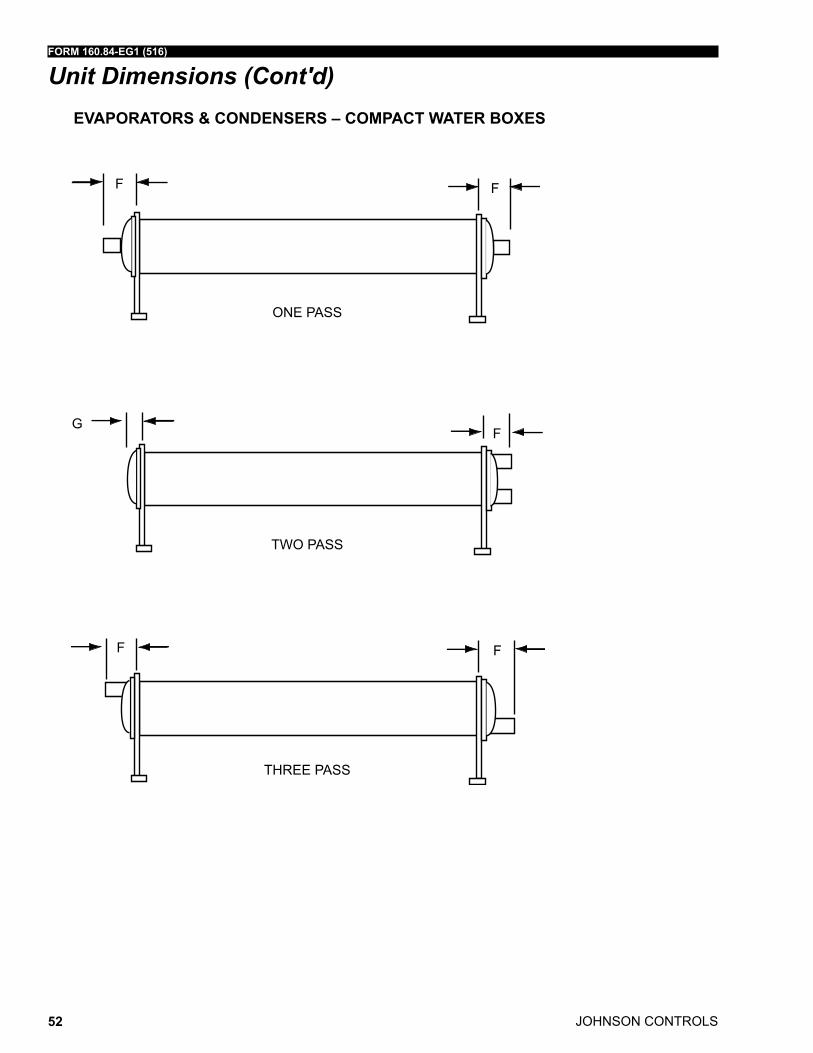
JOHNSON CONTROLS
FORM 160.84-EG1 (516)
52
Unit Dimensions (Cont'd)
F F
F F
FG
ONE PASS
TWO PASS
THREE PASS
EVAPORATORS & CONDENSERS – COMPACT WATER BOXES
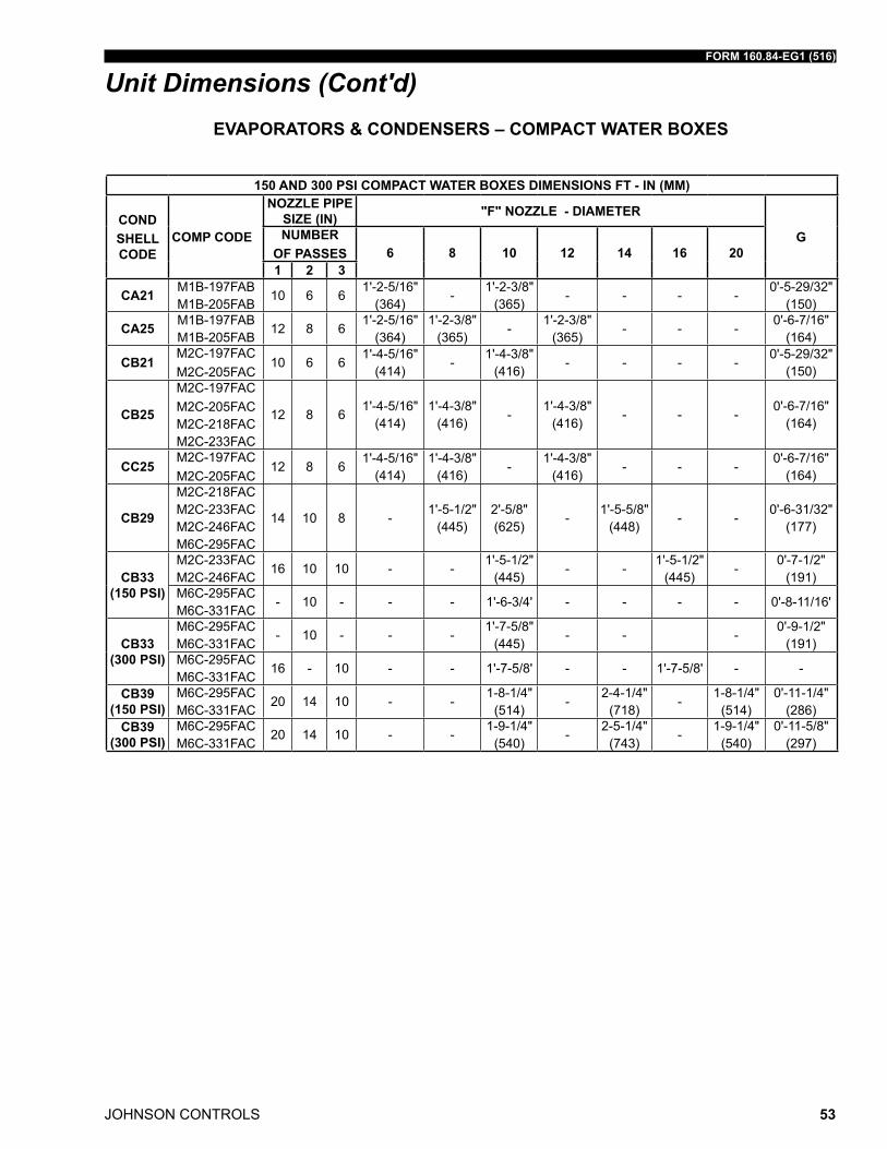
FORM 160.84-EG1 (516)
JOHNSON CONTROLS 53
Unit Dimensions (Cont'd)
150 AND 300 PSI COMPACT WATER BOXES DIMENSIONS FT - IN (MM)
CONDSHELL CODE
COMP CODE
NOZZLE PIPE SIZE (IN) "F" NOZZLE - DIAMETER
GNUMBER OF PASSES 6 8 10 12 14 16 201 2 3
CA21 m1B-197faB m1B-205faB
10 6 61'-2-5/16"
(364)-
1'-2-3/8" (365)
- - - -0'-5-29/32"
(150)
CA25 m1B-197faB m1B-205faB
12 8 61'-2-5/16"
(364)1'-2-3/8"
(365)-
1'-2-3/8" (365)
- - -0'-6-7/16"
(164)
CB21m2C-197faCm2C-205faC
10 6 61'-4-5/16"
(414)-
1'-4-3/8" (416)
- - - -0'-5-29/32"
(150)
CB25
m2C-197faCm2C-205faC m2C-218faC m2C-233faC
12 8 61'-4-5/16"
(414)1'-4-3/8"
(416)-
1'-4-3/8" (416)
- - -0'-6-7/16"
(164)
CC25m2C-197faCm2C-205faC
12 8 61'-4-5/16"
(414)1'-4-3/8"
(416)-
1'-4-3/8" (416)
- - -0'-6-7/16"
(164)
CB29
m2C-218faC m2C-233faC m2C-246faC m6C-295faC
14 10 8 -1'-5-1/2"
(445)2'-5/8" (625)
-1'-5-5/8"
(448)- -
0'-6-31/32" (177)
CB33 (150 PSI)
m2C-233faC m2C-246faC
16 10 10 - -1'-5-1/2"
(445)- -
1'-5-1/2" (445)
-0'-7-1/2"
(191)m6C-295faC m6C-331faC
- 10 - - - 1'-6-3/4' - - - - 0'-8-11/16'
CB33 (300 PSI)
m6C-295faC m6C-331faC
- 10 - - -1'-7-5/8"
(445)- - -
0'-9-1/2" (191)
m6C-295faC m6C-331faC
16 - 10 - - 1'-7-5/8' - - 1'-7-5/8' - -
CB39 (150 PSI)
m6C-295faC m6C-331faC
20 14 10 - -1-8-1/4"
(514)-
2-4-1/4" (718)
-1-8-1/4"
(514)0'-11-1/4"
(286)CB39
(300 PSI)m6C-295faC m6C-331faC
20 14 10 - -1-9-1/4"
(540)-
2-5-1/4" (743)
-1-9-1/4"
(540)0'-11-5/8"
(297)
EVAPORATORS & CONDENSERS – COMPACT WATER BOXES
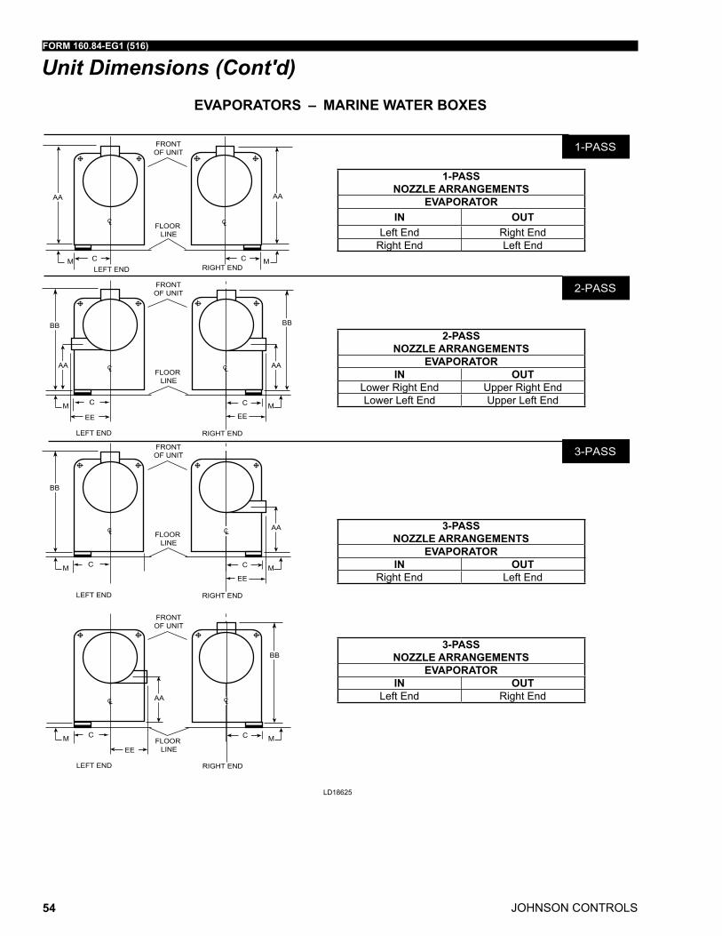
JOHNSON CONTROLS
FORM 160.84-EG1 (516)
54
Unit Dimensions (Cont'd)EVAPORATORS – MARINE WATER BOXES
ld18625
1-PASS NOZZLE ARRANGEMENTS
EVAPORATORIN OUT
left End right Endright End left End
2-PASS NOZZLE ARRANGEMENTS
EVAPORATORIN OUT
lower right End upper right Endlower left End upper left End
3-PASS NOZZLE ARRANGEMENTS
EVAPORATORIN OUT
right End left End
3-PASS NOZZLE ARRANGEMENTS
EVAPORATORIN OUT
left End right End
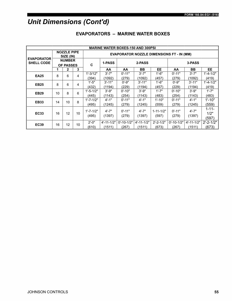
FORM 160.84-EG1 (516)
JOHNSON CONTROLS 55
Unit Dimensions (Cont'd)
MARINE WATER BOXES-150 AND 300PSI
EVAPORATOR SHELL CODE
NOZZLE PIPE SIZE (IN) EVAPORATOR NOZZLE DIMENSIONS FT - IN (MM)
NUMBER OF PASSES C 1-PASS 2-PASS 3-PASS
1 2 3 AA AA BB EE AA BB EE
EA25 8 6 41'-3/12" (394)
3'-7" (1092)
0'-11" (279)
3'-7" (1092)
1'-6" (457)
0'-11" (279)
3'-7" (1092)
1'-4-1/2" (419)
EB25 8 6 41'-5" (432)
3'-11" (1194)
0'-9" (229)
3'-11" (1194)
1'-6" (457)
0'-9" (229)
3'-11" (1194)
1'-4-1/2" (419)
EB29 10 8 61'-5-1/2"
(445)3'-9"
(1143)0'-10" (254)
3'-9" (1143)
1'-7" (483)
0'-10" (254)
3'-9" (1143)
1'-7" (483)
EB33 14 10 81'-7-1/2"
(495)4'-1"
(1245)0'-11" (279)
4'-1" (1245)
1'-10" (559)
0'-11" (279)
4'-1" (1245)
1'-10" (559)
EC33 16 12 101'-7-1/2"
(495)4'-7"
(1397)0'-11" (279)
4'-7" (1397)
1-11-1/2" (597)
0'-11" (279)
4'-7" (1397)
1-11-1/2"
(597)
EC39 16 12 102'-0" (610)
4'-11-1/2" (1511)
0'-10-1/2" (267)
4'-11-1/2" (1511)
2'-2-1/2" (673)
0'-10-1/2" (267)
4'-11-1/2" (1511)
2'-2-1/2" (673)
EVAPORATORS – MARINE WATER BOXES
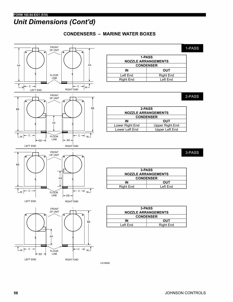
JOHNSON CONTROLS
FORM 160.84-EG1 (516)
56
Unit Dimensions (Cont'd)CONDENSERS – MARINE WATER BOXES
ld18626
1-PASS NOZZLE ARRANGEMENTS
CONDENSERIN OUT
left End right Endright End left End
2-PASS NOZZLE ARRANGEMENTS
CONDENSERIN OUT
lower right End upper right Endlower left End upper left End
3-PASS NOZZLE ARRANGEMENTS
CONDENSERIN OUT
right End left End
3-PASS NOZZLE ARRANGEMENTS
CONDENSERIN OUT
left End right End
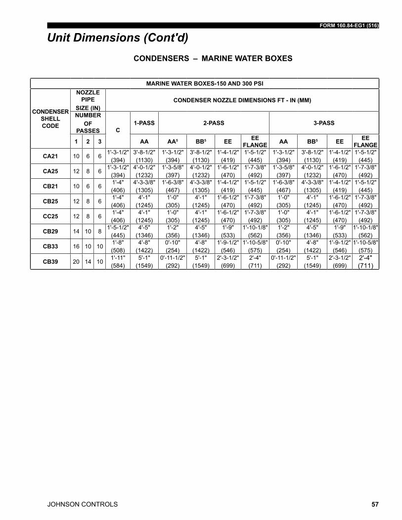
FORM 160.84-EG1 (516)
JOHNSON CONTROLS 57
Unit Dimensions (Cont'd)
MARINE WATER BOXES-150 AND 300 PSI
CONDENSER SHELL CODE
NOZZLE PIPE
SIZE (IN)CONDENSER NOZZLE DIMENSIONS FT - IN (MM)
NUMBER OF
PASSES C1-PASS 2-PASS 3-PASS
1 2 3 AA AA5 BB5 EE EE FLANGE AA BB5 EE EE
FLANGE
CA21 10 6 61'-3-1/2"
(394)3'-8-1/2" (1130)
1'-3-1/2" (394)
3'-8-1/2" (1130)
1'-4-1/2" (419)
1'-5-1/2" (445)
1'-3-1/2" (394)
3'-8-1/2" (1130)
1'-4-1/2" (419)
1'-5-1/2" (445)
CA25 12 8 61'-3-1/2"
(394)4'-0-1/2" (1232)
1'-3-5/8" (397)
4'-0-1/2" (1232)
1'-6-1/2" (470)
1'-7-3/8" (492)
1'-3-5/8" (397)
4'-0-1/2" (1232)
1'-6-1/2" (470)
1'-7-3/8" (492)
CB21 10 6 61'-4" (406)
4'-3-3/8" (1305)
1'-6-3/8" (467)
4'-3-3/8" (1305)
1'-4-1/2" (419)
1'-5-1/2" (445)
1'-6-3/8" (467)
4'-3-3/8" (1305)
1'-4-1/2" (419)
1'-5-1/2" (445)
CB25 12 8 61'-4" (406)
4'-1" (1245)
1'-0" (305)
4'-1" (1245)
1'-6-1/2" (470)
1'-7-3/8" (492)
1'-0" (305)
4'-1" (1245)
1'-6-1/2" (470)
1'-7-3/8" (492)
CC25 12 8 61'-4" (406)
4'-1" (1245)
1'-0" (305)
4'-1" (1245)
1'-6-1/2" (470)
1'-7-3/8" (492)
1'-0" (305)
4'-1" (1245)
1'-6-1/2" (470)
1'-7-3/8" (492)
CB29 14 10 81'-5-1/2"
(445)4'-5"
(1346)1'-2" (356)
4'-5" (1346)
1'-9" (533)
1'-10-1/8" (562)
1'-2" (356)
4'-5" (1346)
1'-9" (533)
1'-10-1/8" (562)
CB33 16 10 101'-8" (508)
4'-8" (1422)
0'-10" (254)
4'-8" (1422)
1'-9-1/2" (546)
1'-10-5/8" (575)
0'-10" (254)
4'-8" (1422)
1'-9-1/2" (546)
1'-10-5/8" (575)
CB39 20 14 101'-11" (584)
5'-1" (1549)
0'-11-1/2" (292)
5'-1" (1549)
2'-3-1/2" (699)
2'-4" (711)
0'-11-1/2" (292)
5'-1" (1549)
2'-3-1/2" (699)
2'-4" (711)
CONDENSERS – MARINE WATER BOXES
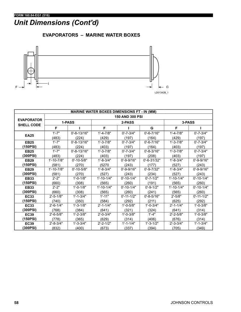
JOHNSON CONTROLS
FORM 160.84-EG1 (516)
58
Unit Dimensions (Cont'd)EVAPORATORS – MARINE WATER BOXES
MARINE WATER BOXES DIMENSIONS FT - IN (MM)
EVAPORATOR SHELL CODE
150 AND 300 PSI1-PASS 2-PASS 3-PASS
F I F I G F I
EA25 1'-7" (483)
0'-8-13/16" (224)
1'-4-7/8" (429)
0'-7-3/4" (197)
0'-6-7/16" (164)
1'-4-7/8" (429)
0'-7-3/4" (197)
EB25 (150PSI)
1'-7" (483)
0'-8-13/16" (224)
1'-3-7/8" (403)
0'-7-3/4" (197)
0'-6-7/16" (164)
1'-3-7/8" (403)
0'-7-3/4" (197)
EB25 (300PSI)
1'-7" (483)
0'-8-13/16" (224)
1'-3-7/8" (403)
0'-7-3/4" (197)
0'-8-3/16" (208)
1'-3-7/8" (403)
0'-7-3/4" (197)
EB29 (150PSI)
1'-10-7/8" (581)
0'-10-5/8" (270)
1'-8-3/4" (5270
0'-9-9/16" (243)
0'-6-31/32" (177)
1'-8-3/4" (527)
0'-9-9/16" (243)
EB29 (300PSI)
1'-10-7/8" (581)
0'-10-5/8" (270)
1'-8-3/4" (527)
0'-9-9/16" (243)
0'-9-7/32" (234)
1'-8-3/4" (527)
0'-9-9/16" (243)
EB33 (150PSI)
2'-2" (660)
1'-0-1/8" (308)
1'-10-1/4" (565)
0'-10-1/4" (260)
0'-7-1/2" (191)
1'-10-1/4" (565)
0'-10-1/4" (260)
EB33 (300PSI)
2'-2" (660)
1'-0-1/8" (308)
1'-10-1/4" (565)
0'-10-1/4" (260)
0'-9-1/2" (241)
1'-10-1/4" (565)
0'-10-1/4" (260)
EC33 (150PSI)
2'-5-1/8" (740)
1'-1-3/4" (350)
1'-11" (584)
0'-11-1/2" (292)
0'-8-5/16" (211)
2'-5/8" (625)
0'-11-1/2" (292)
EC33 (300PSI)
2'-6-1/4" (768)
1'-3-1/8" (384)
2'-1-1/4" (641)
1'-0-5/8" (321)
1'-0-3/4" (324)
2'-1-1/4" (641)
1'-0-3/8" (314)
EC39 (150PSI)
2'-6-5/8" (778)
1'-2-3/8" (365)
2'-0-3/4" (629)
1'-0-3/8" (314)
1'-4" (406)
2'-2-5/8" (676)
1'-0-3/8" (314)
EC39 (300PSI)
2'-8-3/4" (832)
1'-3-3/4" (400)
2'-2-1/2" (673)
1'-1-1/4" (337)
1'-3-1/2" (394)
2'-3-3/4" (705)
1'-1-3/4" (349)
Fld01342B_1
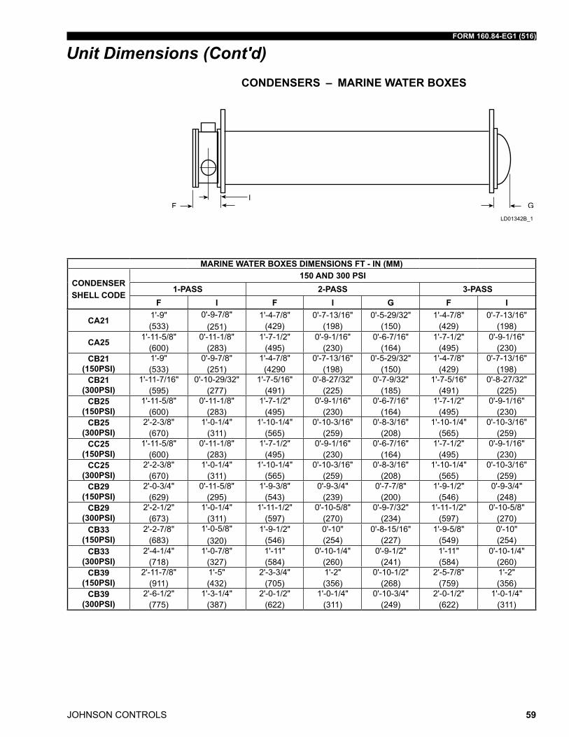
FORM 160.84-EG1 (516)
JOHNSON CONTROLS 59
Unit Dimensions (Cont'd)CONDENSERS – MARINE WATER BOXES
MARINE WATER BOXES DIMENSIONS FT - IN (MM)
CONDENSER SHELL CODE
150 AND 300 PSI1-PASS 2-PASS 3-PASS
F I F I G F I
CA21 1'-9" (533)
0'-9-7/8" (251)
1'-4-7/8" (429)
0'-7-13/16" (198)
0'-5-29/32" (150)
1'-4-7/8" (429)
0'-7-13/16" (198)
CA25 1'-11-5/8" (600)
0'-11-1/8" (283)
1'-7-1/2" (495)
0'-9-1/16" (230)
0'-6-7/16" (164)
1'-7-1/2" (495)
0'-9-1/16" (230)
CB21 (150PSI)
1'-9" (533)
0'-9-7/8" (251)
1'-4-7/8" (4290
0'-7-13/16" (198)
0'-5-29/32" (150)
1'-4-7/8" (429)
0'-7-13/16" (198)
CB21 (300PSI)
1'-11-7/16" (595)
0'-10-29/32" (277)
1'-7-5/16" (491)
0'-8-27/32" (225)
0'-7-9/32" (185)
1'-7-5/16" (491)
0'-8-27/32" (225)
CB25 (150PSI)
1'-11-5/8" (600)
0'-11-1/8" (283)
1'-7-1/2" (495)
0'-9-1/16" (230)
0'-6-7/16" (164)
1'-7-1/2" (495)
0'-9-1/16" (230)
CB25 (300PSI)
2'-2-3/8" (670)
1'-0-1/4" (311)
1'-10-1/4" (565)
0'-10-3/16" (259)
0'-8-3/16" (208)
1'-10-1/4" (565)
0'-10-3/16" (259)
CC25 (150PSI)
1'-11-5/8" (600)
0'-11-1/8" (283)
1'-7-1/2" (495)
0'-9-1/16" (230)
0'-6-7/16" (164)
1'-7-1/2" (495)
0'-9-1/16" (230)
CC25 (300PSI)
2'-2-3/8" (670)
1'-0-1/4" (311)
1'-10-1/4" (565)
0'-10-3/16" (259)
0'-8-3/16" (208)
1'-10-1/4" (565)
0'-10-3/16" (259)
CB29 (150PSI)
2'-0-3/4" (629)
0'-11-5/8" (295)
1'-9-3/8" (543)
0'-9-3/4" (239)
0'-7-7/8" (200)
1'-9-1/2" (546)
0'-9-3/4" (248)
CB29 (300PSI)
2'-2-1/2" (673)
1'-0-1/4" (311)
1'-11-1/2" (597)
0'-10-5/8" (270)
0'-9-7/32" (234)
1'-11-1/2" (597)
0'-10-5/8" (270)
CB33 (150PSI)
2'-2-7/8" (683)
1'-0-5/8"(320)
1'-9-1/2" (546)
0'-10" (254)
0'-8-15/16" (227)
1'-9-5/8" (549)
0'-10" (254)
CB33 (300PSI)
2'-4-1/4" (718)
1'-0-7/8" (327)
1'-11" (584)
0'-10-1/4" (260)
0'-9-1/2" (241)
1'-11" (584)
0'-10-1/4" (260)
CB39 (150PSI)
2'-11-7/8" (911)
1'-5" (432)
2'-3-3/4" (705)
1'-2" (356)
0'-10-1/2" (268)
2'-5-7/8" (759)
1'-2" (356)
CB39 (300PSI)
2'-6-1/2" (775)
1'-3-1/4" (387)
2'-0-1/2" (622)
1'-0-1/4" (311)
0'-10-3/4" (249)
2'-0-1/2" (622)
1'-0-1/4" (311)
Fld01342B_1
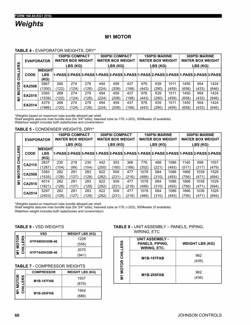
JOHNSON CONTROLS
FORM 160.84-EG1 (516)
60
WeightsM1 MOTOR
TABLE 4 - EVaPorator WEiGhts, drY*
M1
MO
TOR
CH
ILLE
RS EVAPORATOR
150PSI COMPACT WATER BOX WEIGHT
LBS (KG)
300PSI COMPACT WATER BOX WEIGHT
LBS (KG)
150PSI MARINE WATER BOX WEIGHT
LBS (KG)
300PSI MARINE WATER BOX WEIGHT
LBS (KG)
CODEWEIGHT
LBS (KG)
1-PASS 2-PASS 3-PASS 1-PASS 2-PASS 3-PASS 1-PASS 2-PASS 3-PASS 1-PASS 2-PASS 3-PASS
EA2508 2867 (1300)
268 (122)
274 (124)
278 (126)
494 (224)
459 (208)
437 (198)
976 (443)
639 (290)
1011 (459)
1450 (658)
954 (433)
1424 (646)
EA2510 3393 (1539)
268 (122)
274 (124)
278 (126)
494 (224)
459 (208)
437 (198)
976 (443)
639 (290)
1011 (459)
1450 (658)
954 (433)
1424 (646)
EA2514 4379 (1986)
268 (122)
274 (124)
278 (126)
494 (224)
459 (208)
437 (198)
976 (443)
639 (290)
1011 (459)
1450 (658)
954 (433)
1424 (646)
*Weights based on maximum tube bundle allowed per shell.shell weights assume max bundle size (for 3/4" tube), heaviest tube (e-179; c-203), 300#water (if available)Waterbox weight includes both waterboxes and covers/return
TABLE 5 - CondEnsEr WEiGhts, drY*
M1
MO
TOR
CH
ILLE
RS
EVAPORATOR150PSI COMPACT
WATER BOX WEIGHT LBS (KG)
300PSI COMPACT WATER BOX WEIGHT
LBS (KG)
150PSI MARINE WATER BOX WEIGHT
LBS (KG)
300PSI MARINE WATER BOX WEIGHT
LBS (KG)
CODEWEIGHT
LBS (KG)
1-PASS 2-PASS 3-PASS 1-PASS 2-PASS 3-PASS 1-PASS 2-PASS 3-PASS 1-PASS 2-PASS 3-PASS
CA2110 2837 (1287)
230 (104)
219 (99)
230 (104)
442 (200)
353 (160)
366 (166)
776 (352)
488 (221)
1086 (493)
1140 (517)
699 (317)
1057 (479)
CA2508 3383 (1535)
282 (128)
281 (127)
283 (128)
622 (282)
509 (231)
477 (216)
1078 (489)
684 (310)
1086 (493)
1666 (756)
1039 (471)
1529 (694)
CA2510 4014 (1821)
282 (128)
281 (127)
283 (128)
622 (282)
509 (231)
477 (216)
1078 (489)
684 (310)
1086 (493)
1666 (756)
1039 (471)
1529 (694)
CA2514 5297 (2403)
282 (128)
281 (127)
283 (128)
622 (282)
509 (231)
477 (216)
1078 (489)
684 (310)
1086 (493)
1666 (756)
1039 (471)
1529 (694)
*Weights based on maximum tube bundle allowed per shell.shell weights assume max bundle size (for 3/4" tube), heaviest tube (e-179; c-203), 300#water (if available)Waterbox weight includes both waterboxes and covers/return
TABLE 6 - Vsd WEiGhts
M1
MO
TOR
CH
ILLE
RS
VSD WEIGHT LBS (KG)
HyP490XH30B-461226 (556)
HyP744XH30B-462075 (941)
TABLE 7 - ComPrEssor WEiGhts
M1
MO
TOR
CH
ILLE
RS
COMPRESSOR WEIGHT LBS (KG)
M1B-197FAB1937 (879)
M1B-205FAB1954 (886)
TABLE 8 - unit assEmBlY – PanEls, PiPinG, WirinG, EtC
M1
MO
TOR
CH
ILLE
RS
UNIT ASSEMBLy - PANELS, PIPING,
WIRING, ETC.WEIGHT LBS (KG)
M1B-197FAB962
(436)
M1B-205FAB962
(436)
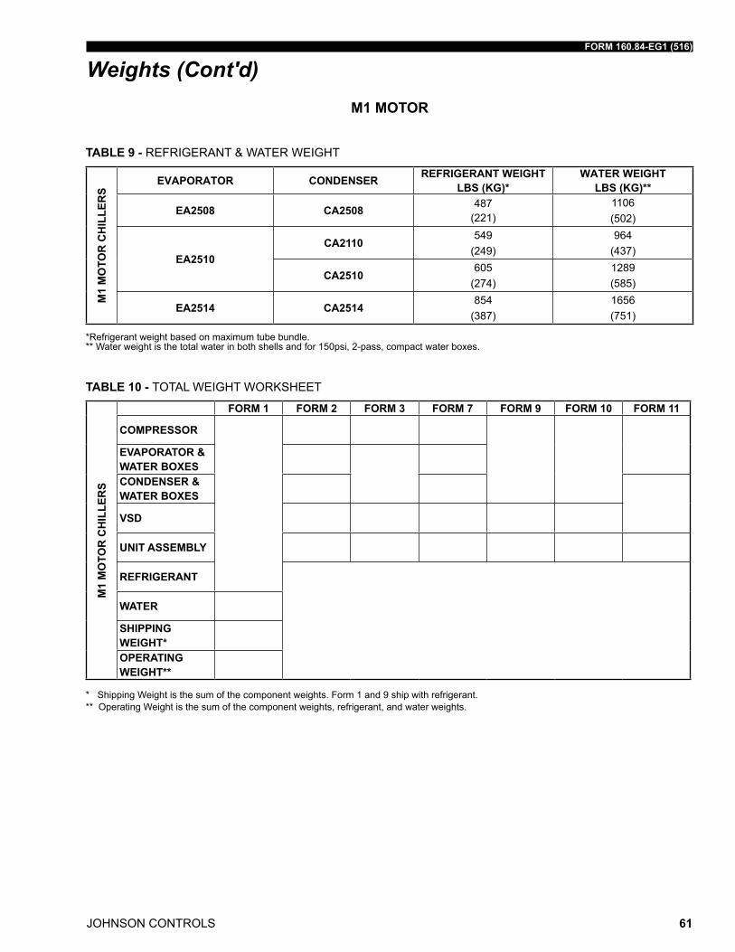
FORM 160.84-EG1 (516)
JOHNSON CONTROLS 61
M1 MOTOR
TABLE 9 - rEfriGErant & WatEr WEiGht
M1
MO
TOR
CH
ILLE
RS
EVAPORATOR CONDENSER REFRIGERANT WEIGHT LBS (KG)*
WATER WEIGHT LBS (KG)**
EA2508 CA2508 487 (221)
1106 (502)
EA2510CA2110
549 (249)
964 (437)
CA2510605
(274)1289 (585)
EA2514 CA2514854
(387)1656 (751)
*refrigerant weight based on maximum tube bundle.** Water weight is the total water in both shells and for 150psi, 2-pass, compact water boxes.
TABLE 10 - total WEiGht WorKshEEt
M1
MO
TOR
CH
ILLE
RS
FORM 1 FORM 2 FORM 3 FORM 7 FORM 9 FORM 10 FORM 11
COMPRESSOR
EVAPORATOR & WATER BOXES
CONDENSER & WATER BOXES
VSD
UNIT ASSEMBLy
REFRIGERANT
WATER
SHIPPING WEIGHT*OPERATING WEIGHT**
* shipping Weight is the sum of the component weights. form 1 and 9 ship with refrigerant. ** operating Weight is the sum of the component weights, refrigerant, and water weights.
Weights (Cont'd)
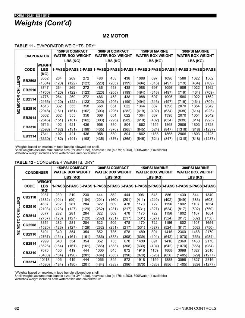
JOHNSON CONTROLS
FORM 160.84-EG1 (516)
62
Weights (Cont'd)
TABLE 11 - EVaPorator WEiGhts, drY*
M2
MO
TOR
CH
ILLE
RS
EVAPORATOR150PSI COMPACT
WATER BOX WEIGHT LBS (KG)
300PSI COMPACT WATER BOX WEIGHT
LBS (KG)
150PSI MARINE WATER BOX WEIGHT
LBS (KG)
300PSI MARINE WATER BOX WEIGHT
LBS (KG)
CODEWEIGHT
LBS (KG)
1-PASS 2-PASS 3-PASS 1-PASS 2-PASS 3-PASS 1-PASS 2-PASS 3-PASS 1-PASS 2-PASS 3-PASS
EB2508 3052 (1384)
264 (120)
269 (122)
272 (123)
486 (220)
453 (205)
438 (199)
1088 (494)
697 (316)
1096 (497)
1586 (719)
1022 (464)
1562 (709)
EB2510 3747 (1700)
264 (120)
269 (122)
272 (123)
486 (220)
453 (205)
438 (199)
1088 (494)
697 (316)
1096 (497)
1586 (719)
1022 (464)
1562 (709)
EB2514 4776 (2166)
264 (120)
269 (122)
272 (123)
486 (220)
453 (205)
438 (199)
1088 (494)
697 (316)
1096 (497)
1586 (719)
1022 (464)
1562 (709)
EB2910 4516 (2048)
332 (151)
355 (161)
358 (162)
668 (303)
651 (295)
622 (282)
1364 (619)
887 (402)
1398 (634)
2070 (939)
1354 (614)
2042 (926)
EB2914 5832 (2645)
332 (151)
355 (161)
358 (162)
668 (303)
651 (295)
622 (282)
1364 (619)
887 (402)
1398 (634)
2070 (939)
1354 (614)
2042 (926)
EB3310 5716 (2593)
402 (182)
421 (191)
436 (198)
958 (435)
830 (376)
804 (365)
1862 (845)
1155 (524)
1868 (847)
2906 (1318)
1803 (818)
2728 (1237)
EB3314 7341 (3330)
402 (182)
421 (191)
436 (198)
958 (435)
830 (376)
804 (365)
1862 (845)
1155 (524)
1868 (847)
2906 (1318)
1803 (818)
2728 (1237)
*Weights based on maximum tube bundle allowed per shell.shell weights assume max bundle size (for 3/4" tube), heaviest tube (e-179; c-203), 300#water (if available)Waterbox weight includes both waterboxes and covers/return
M2 MOTOR
TABLE 12 - CondEnsEr WEiGhts, drY*
M2
MO
TOR
CH
ILLE
RS
CONDENSER150PSI COMPACT
WATER BOX WEIGHT LBS (KG)
300PSI COMPACT WATER BOX WEIGHT
LBS (KG)
150PSI MARINE WATER BOX WEIGHT
LBS (KG)
300PSI MARINE WATER BOX WEIGHT
LBS (KG)
CODEWEIGHT
LBS (KG)
1-PASS 2-PASS 3-PASS 1-PASS 2-PASS 3-PASS 1-PASS 2-PASS 3-PASS 1-PASS 2-PASS 3-PASS
CB2110 2937 (1332)
230 (104)
219 (99)
230 (104)
444 (201)
352 (160)
444 (201)
906 (411)
548 (249)
886 (402)
1430 (649)
844 (383)
1340 (608)
CB2510 4637 (2103)
282 (128)
281 (127)
284 (129)
622 (282)
509 (231)
478 (217)
1170 (531)
722 (327)
1156 (524)
1802 (817)
1107 (502)
1654 (750)
CB2514 6077 (2757)
282 (128)
281 (127)
284 (129)
622 (282)
509 (231)
478 (217)
1170 (531)
722 (327)
1156 (524)
1802 (817)
1107 (502)
1654 (750)
CC2508 3351 (1520)
282 (128)
281 (127)
284 (129)
622 (282)
509 (231)
478 (217)
1170 (531)
722 (327)
1156 (524)
1802 (817)
1107 (502)
1654 (750)
CB2910 6101 (2767)
340 (154)
354 (161)
354 (161)
852 (386)
735 (333)
678 (308)
1480 (639)
891 (404)
1416 (642)
2360 (1070)
1468 (666)
2170 (984)
CB2914 7999 (3628)
340 (154)
354 (161)
354 (161)
852 (386)
735 (333)
678 (308)
1480 (639)
891 (404)
1416 (642)
2360 (1070)
1468 (666)
2170 (984)
CB3310 7673 (3480)
406 (184)
419 (190)
444 (201)
1066 (484)
845 (383)
872 (396)
1918 (870)
1159 (526)
1888 (856)
3098 (1405)
1827 (829)
2816 (1277)
CB3314 10118 (4590)
406 (184)
419 (190)
444 (201)
1066 (484)
845 (383)
872 (396)
1918 (870)
1159 (526)
1888 (856)
3098 (1405)
1827 (829)
2816 (1277)
*Weights based on maximum tube bundle allowed per shell.shell weights assume max bundle size (for 3/4" tube), heaviest tube (e-179; c-203), 300#water (if available)Waterbox weight includes both waterboxes and covers/return
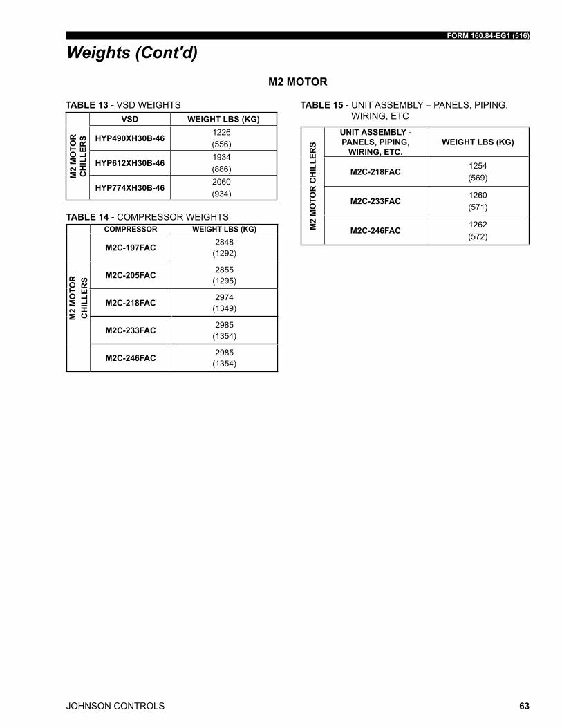
FORM 160.84-EG1 (516)
JOHNSON CONTROLS 63
Weights (Cont'd)
TABLE 13 - Vsd WEiGhts
M2
MO
TOR
C
HIL
LER
S
VSD WEIGHT LBS (KG)
HyP490XH30B-461226 (556)
HyP612XH30B-461934(886)
HyP774XH30B-462060 (934)
TABLE 14 - ComPrEssor WEiGhts
M2
MO
TOR
C
HIL
LER
S
COMPRESSOR WEIGHT LBS (KG)
M2C-197FAC 2848 (1292)
M2C-205FAC 2855 (1295)
M2C-218FAC 2974 (1349)
M2C-233FAC 2985 (1354)
M2C-246FAC 2985 (1354)
TABLE 15 - unit assEmBlY – PanEls, PiPinG, WirinG, EtC
M2
MO
TOR
CH
ILLE
RS
UNIT ASSEMBLy - PANELS, PIPING,
WIRING, ETC.WEIGHT LBS (KG)
M2C-218FAC1254(569)
M2C-233FAC1260(571)
M2C-246FAC1262(572)
M2 MOTOR
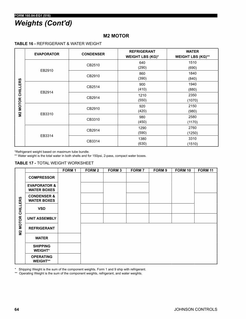
JOHNSON CONTROLS
FORM 160.84-EG1 (516)
64
Weights (Cont'd)
TABLE 16 - rEfriGErant & WatEr WEiGht
M2
MO
TOR
CH
ILLE
RS
EVAPORATOR CONDENSERREFRIGERANT
WEIGHT LBS (KG)*WATER
WEIGHT LBS (KG)**
EB2910CB2510
640 (290)
1510(690)
CB2910860
(390)1840(840)
EB2914CB2514
900 (410)
1940(880)
CB29141210 (550)
2350(1070)
EB3310CB2910
920 (420)
2150(980)
CB3310980
(450)2580
(1170)
EB3314CB2914
1290 (590)
2760(1250)
CB33141380 (630)
3310(1510)
*refrigerant weight based on maximum tube bundle.** Water weight is the total water in both shells and for 150psi, 2-pass, compact water boxes.
TABLE 17 - total WEiGht WorKshEEt
M2
MO
TOR
CH
ILLE
RS
FORM 1 FORM 2 FORM 3 FORM 7 FORM 9 FORM 10 FORM 11
COMPRESSOR
EVAPORATOR & WATER BOXES
CONDENSER & WATER BOXES
VSD
UNIT ASSEMBLy
REFRIGERANT
WATER
SHIPPING WEIGHT*
OPERATING WEIGHT**
* shipping Weight is the sum of the component weights. form 1 and 9 ship with refrigerant. ** operating Weight is the sum of the component weights, refrigerant, and water weights.
M2 MOTOR
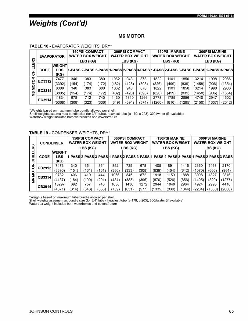
FORM 160.84-EG1 (516)
JOHNSON CONTROLS 65
Weights (Cont'd)
TABLE 18 - EVaPorator WEiGhts, drY*
M6
MO
TOR
CH
ILLE
RS EVAPORATOR
150PSI COMPACT WATER BOX WEIGHT
LBS (KG)
300PSI COMPACT WATER BOX WEIGHT
LBS (KG)
150PSI MARINE WATER BOX WEIGHT
LBS (KG)
300PSI MARINE WATER BOX WEIGHT
LBS (KG)
CODEWEIGHT
LBS (KG)
1-PASS 2-PASS 3-PASS 1-PASS 2-PASS 3-PASS 1-PASS 2-PASS 3-PASS 1-PASS 2-PASS 3-PASS
EC3312 7477 (3392)
340 (154)
383 (174)
380 (172)
1062 (482)
943 (428)
878 (398)
1822 (826)
1101 (499)
1850 (839)
3214 (1458)
1998 (906)
2986 (1354)
EC3314 8389 (3805)
340 (154)
383 (174)
380 (172)
1062 (482)
943 (428)
878 (398)
1822 (826)
1101 (499)
1850 (839)
3214 (1458)
1998 (906)
2986 (1354)
EC3914 11834 (5368)
678 (308)
712 (323)
740 (336)
1430 (649)
1310 (594)
1266 (574)
2778 (1260)
1785 (810)
2856 (1295)
4740 (2150)
2947 (1337)
4502 (2042)
*Weights based on maximum tube bundle allowed per shell.shell weights assume max bundle size (for 3/4" tube), heaviest tube (e-179; c-203), 300#water (if available)Waterbox weight includes both waterboxes and covers/return
M6 MOTOR
TABLE 19 - CondEnsEr WEiGhts, drY*
M6
MO
TOR
CH
ILLE
RS CONDENSER
150PSI COMPACT WATER BOX WEIGHT
LBS (KG)
300PSI COMPACT WATER BOX WEIGHT
LBS (KG)
150PSI MARINE WATER BOX WEIGHT
LBS (KG)
300PSI MARINE WATER BOX WEIGHT
LBS (KG)
CODEWEIGHT
LBS (KG)
1-PASS 2-PASS 3-PASS 1-PASS 2-PASS 3-PASS 1-PASS 2-PASS 3-PASS 1-PASS 2-PASS 3-PASS
CB2912 7473 (3390)
340 (154)
354 (161)
354 (161)
852 (386)
735 (333)
678 (308)
1408 (639)
891 (404)
1416 (642)
2360 (1070)
1468 (666)
2170 (984)
CB3314 9782 (4437)
406 (184)
419 (190)
444 (201)
1066 (484)
845 (383)
872 (396)
1918 (870)
1159 (526)
1888 (856)
3098 (1405)
1827 (829)
2816 (1277)
CB3914 10297 (4671)
692 (314)
757 (343)
740 (336)
1630 (739)
1436 (651)
1272 (577)
2944 (1335)
1849 (839)
2964 (1344)
4924 (2234)
2998 (1360)
4410 (2000)
*Weights based on maximum tube bundle allowed per shell.shell weights assume max bundle size (for 3/4" tube), heaviest tube (e-179; c-203), 300#water (if available)Waterbox weight includes both waterboxes and covers/return
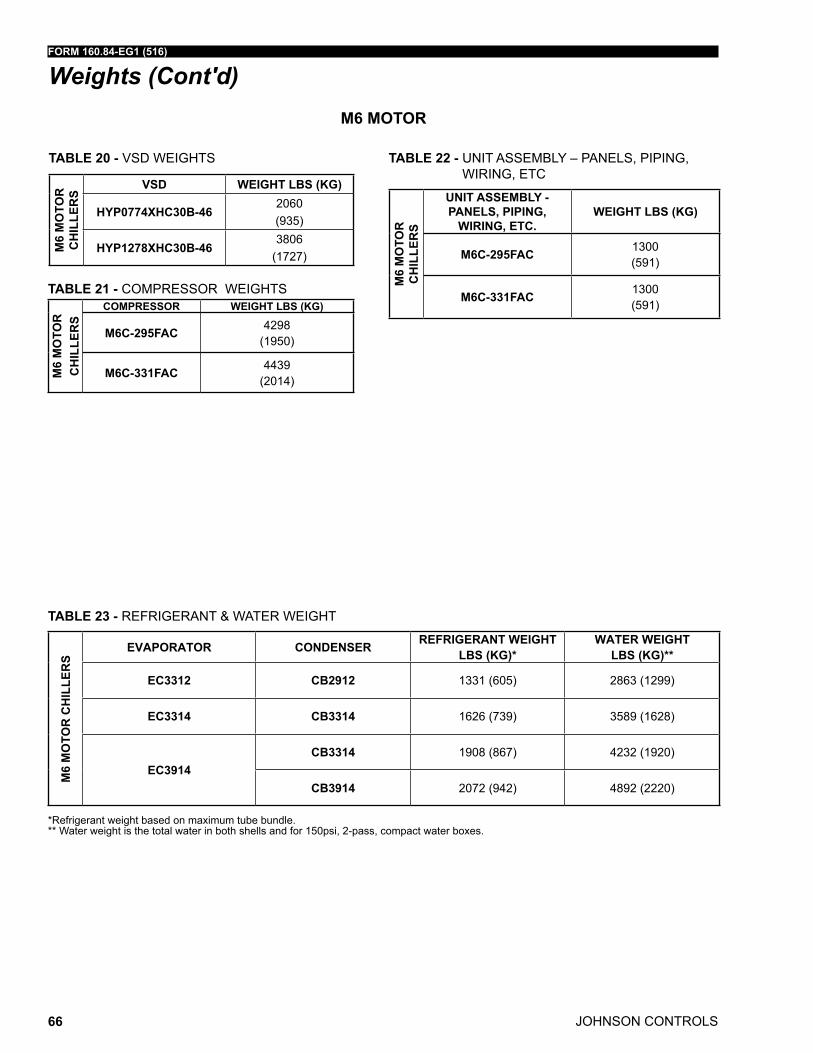
JOHNSON CONTROLS
FORM 160.84-EG1 (516)
66
M6 MOTOR
Weights (Cont'd)
TABLE 20 - Vsd WEiGhts
M6
MO
TOR
C
HIL
LER
S
VSD WEIGHT LBS (KG)
HyP0774XHC30B-462060(935)
HyP1278XHC30B-463806
(1727)
TABLE 21 - ComPrEssor WEiGhts
M6
MO
TOR
C
HIL
LER
S
COMPRESSOR WEIGHT LBS (KG)
M6C-295FAC 4298 (1950)
M6C-331FAC 4439 (2014)
TABLE 22 - unit assEmBlY – PanEls, PiPinG, WirinG, EtC
M6
MO
TOR
C
HIL
LER
S
UNIT ASSEMBLy - PANELS, PIPING,
WIRING, ETC.WEIGHT LBS (KG)
M6C-295FAC 1300 (591)
M6C-331FAC 1300 (591)
TABLE 23 - rEfriGErant & WatEr WEiGht
M6
MO
TOR
CH
ILLE
RS
EVAPORATOR CONDENSER REFRIGERANT WEIGHT LBS (KG)*
WATER WEIGHT LBS (KG)**
EC3312 CB2912 1331 (605) 2863 (1299)
EC3314 CB3314 1626 (739) 3589 (1628)
EC3914CB3314 1908 (867) 4232 (1920)
CB3914 2072 (942) 4892 (2220)
*refrigerant weight based on maximum tube bundle.** Water weight is the total water in both shells and for 150psi, 2-pass, compact water boxes.
FORM 160.84-EG1 (516)
JOHNSON CONTROLS 67
Guide Specifications
GENERAL
furnish YorK YmC² unit(s) as indicated on the drawings.
Each unit shall produce a capacity of ____ tons, cooling ____ gpm of _____ from ____ to ____ °f when supplied with ____ gpm of condenser water at ____°f. Power input shall not exceed ____ kW with an iPlV of ____. the cooler shall be selected for _____ fouling factor and a maximum liquid pressure drop of ____ ft. Water side shall be designed for ____ psig working pressure. the condenser shall be selected for _____ fouling factor and maximum liquid pressure drop of ___ ft. Water side shall be designed for ____ psig working pressure. Power shall be supplied to the unit at ____ volts - 3 phase - ___ hz. the chiller shall use hfC-134a.
or
Each unit shall produce a capacity of ____ kW, cooling ____ l/s of _____ from ____ to ____ °C when supplied with ____ l/s of condenser water at ____°C. Power input shall not exceed ____ KW with an iPlV of ____. the cooler shall be selected for _____ m2 C/W fouling factor and a maximum liquid pressure drop of ____ kPa. Water side shall be de-signed for ____ barg working pressure. the condenser shall be selected for _____ foul-ing factor and maximum liquid pressure drop of ___ kPa. Water side shall be designed for ____ barg working pressure. Power shall be supplied to the unit at ____ volts - 3 phase - ___ hz. the chiller shall use hfC-134a.
Each unit shall be completely factory packaged including evaporator, unit mounted op-tispeed Vsd, condenser, sub-cooler, compressor, hermetic motor, optiView Control Cen-ter, and all interconnecting unit piping and wiring. the chiller shall be painted prior to shipment.
Performance shall be certified in accordance with ahri standard 550/590. only chillers that are listed in the ahri Certification Program for Centrifugal and rotary screw Water Chillers are acceptable.
the initial charge of refrigerant shall be supplied, factory charged in the chiller or shipped in containers and cylinders for field installation.
COMPRESSOR
the compressor shall be a single-stage centrifugal type powered by a high speed, direct-drive electric motor. a cast aluminum, fully shrouded impeller shall be mounted directly to the motor shaft. the impeller shall be designed for balanced thrust, dynamically balanced and overspeed tested for smooth, vibration free operation. Compressor castings shall be designed for 235 psig (16 barg) working pressure and hydrostatically pressure tested at 355 psig (24.4 barg) for hfC-134a units.
Capacity control shall be achieved by the combined use of variable speed control and mechanical flow regulation to provide fully modulating control from maximum to minimum load. the unit shall be capable of operating with lower temperature cooling tower water during part-load operation in accordance with ahri standard 550/590. all capacity con-trol devices shall be automatically controlled to maintain a constant leaving chilled water temperature.
JOHNSON CONTROLS
FORM 160.84-EG1 (516)
68
Guide Specifications (Cont'd)MOTOR
the compressor motor shall be a hermetic, oil free, permanent magnet type directly cou-pled to the compressor. the motor will be bolted to a cast iron adapter plate mounted on the compressor to provide factory alignment of the shaft. the motor shaft shall be supported on active magnetic radial and thrust bearings. magnetic bearing control shall be equipped with auto vibration reduction and balancing systems. during a power failure event, the magnetic bearings shall remain active throughout the compressor coast down. rolling element bearings shall be provided as a backup to the magnetic bearings de-signed for emergency touch down situations. motor stator and rotor shall be equipped with a pressure driven refrigerant cooling loop to maintain acceptable operating temperatures.
VARIABLE-SPEED DRIVE (VSD)
a Vsd shall be factory installed on the chiller. it will vary the compressor motor speed by controlling the frequency and voltage of the electrical power to the motor. the capacity control logic shall automatically adjust motor speed for maximum part-load efficiency by analyzing information fed to it by sensors located throughout the chiller.
drive shall be PWm type utilizing iGBt’s with a displacement power factor of 0.97 or bet-ter at all loads and speeds.
the Vsd shall be unit mounted in a nEma -1 enclosure with all power and control wiring between the drive and chiller factory installed. field power wiring shall be a single point connection and electrical lugs for incoming power wiring will be provided. the entire chiller package shall be ul listed.
the Vsd shall be cooled using condenser water and all cooling connections shall be fac-tory installed.
the following features will be provided:
• door interlocked rotary disconnect switch or circuit breaker capable of being pad-locked.
• Ground fault protection.
• over-voltage and under-voltage protection.
• 3-phase sensing motor over current protection.
• 3-phase sensing input over current protection.
• single phase protection.
• insensitive to phase rotation.
• over temperature protection.
• iEEE standard 519-1992 compliance.
• digital readout at the chiller unit control panel of output frequency, output voltage, 3-phase input current, 3-phase output current, input kVa, Kilowatts and Kilowatt-hours, input voltage thd, input current tdd, self-diagnostic service parameters. separate meters for this information will not be acceptable.
FORM 160.84-EG1 (516)
JOHNSON CONTROLS 69
Guide Specifications (Cont'd)• KW Meter - the unit’s input power consumption will be measured and displayed
digitally via the unit’s control panel. the KW meter accuracy is typically +/- 3% of reading. KW meter scale is 0 - 788 KW.
• KWh Meter – the unit’s cumulative input power consumption is measured and dis-played digitally via the unit’s control panel. the KWh meter is resettable and its ac-curacy is typically +/- 3% of reading. KWh meter scale is 0 – 999,999 kWh.
• Ammeter – simultaneous three-phase true rms digital readout via the unit control panel. six current transformers provide isolated sensing. the ammeter accuracy is typically +/- 3% of reading. ammeter scale is 0 - 545 a rms.
• Voltmeter – simultaneous three-phase true rms digital readout of input voltage and motor voltage via the unit control panel. the voltmeter accuracy is typically +/- 3% of reading. Voltmeter scale is 0 – 670 VaC.
• Elapsed Time Meter – digital readout of the unit’s elapsed running time (0 – 876,600 hours, resetable) is displayed via the unit control panel.
EVAPORATOR
Evaporator shall be a shell and tube, hybrid falling-film type designed for 235 psig (16 barg) working pressure on the refrigerant side. shell shall be fabricated from rolled carbon steel plate with fusion welded seams; have carbon steel tube sheets, drilled and reamed to accommodate the tubes; and intermediate tube supports spaced no more than four feet apart. the refrigerant side shall be designed, tested and stamped in accordance with asmE Boiler and Pressure Vessel Code, section Viii-division 1.
tubes shall be high-efficiency, internally and externally enhanced type having plain cop-per lands at all intermediate tube supports to provide maximum tube wall thickness at the support area. Each tube shall be roller expanded into the tube sheets providing a leak proof seal, and be individually replaceable. Water velocity through the tubes shall not exceed 12 fps. a liquid level sight glass will be located on the side of the shell to aid in determining proper refrigerant charge. a suction baffle eliminator will be located above the tube bundle to prevent liquid refrigerant carryover to the compressor. the evaporator shall have a refrigerant relief device sized to meet the requirements of ashraE 15 safety Code for mechanical refrigeration.
Water boxes shall be removable to permit tube cleaning and replacement. stubout water nozzle connections having ansi/aWWa C-606 grooves shall be provided. Waterboxes shall be designed for 150 psi (10.3 bar) design working pressure and tested at 225 psig (15.5 bar). Vent and drain connections with plugs will be provided on each water box. low flow protection shall be provided by a thermal-type flow sensor, factory mounted in the water nozzle connection and wired to the chiller optiView Control Center.
CONDENSER
Condenser shall be of the shell and tube type, designed for 235 psig (16 barg) working pressure on the refrigerant side. shell shall be fabricated from rolled carbon steel plate with fusion welded seams; have carbon steel tube sheets, drilled and reamed to accom-modate the tubes; and intermediate tube supports spaced no more than four feet apart. the refrigerant side shall be designed, tested and stamped in accordance with asmE Boiler and Pressure Vessel Code, section Viii-division 1. tubes shall be high-efficiency,
JOHNSON CONTROLS
FORM 160.84-EG1 (516)
70
Guide Specifications (Cont'd)internally and externally enhanced type having plain copper lands at all intermediate tube supports to provide maximum tube wall thickness at the support area. Each tube shall be roller expanded into the tube sheets providing a leak proof seal, and be individually replaceable. Water velocity through the tubes shall not exceed 12 fps.
Water boxes shall be removable to permit tube cleaning and replacement. stubout water connections having ansi/aWWa C-606 grooves will be provided. Waterboxes shall be designed for 150 psi (10.3 bar) design working pressure and tested at 225 psig (15.5 bar). Vent and drain connections with plugs will be provided on each water box.
REFRIGERANT ISOLATION VALVES
factory-installed isolation valves in the compressor discharge line and refrigerant liquid line shall be provided. these valves shall allow isolation and storage of the refrigerant charge in the chiller condenser during servicing, eliminating time-consuming transfers to remote storage vessels. Both valves shall be positive shutoff, assuring integrity of the storage system.
REFRIGERANT FLOW CONTROL
refrigerant flow to the evaporator shall be controlled by a variable orifice. the variable orifice control shall automatically adjust to maintain proper refrigerant level in the con-denser and evaporator. this shall be controlled by monitoring refrigerant liquid level in the condenser, assuring optimal subcooler performance.
OPTIVIEW CONTROL CENTER
the chiller shall be controlled by a standalone microprocessor based control center. the chiller optiView Control Center shall provide control of chiller operation and monitoring of chiller sensors, actuators, relays and switches.
the control panel shall include a 10.4 in. diagonal color liquid crystal display (lCd) sur-rounded by “soft“ keys which are redefined based on the screen displayed at that time. this shall be mounted in the middle of a keypad interface and installed in a locked enclo-sure. the screen shall detail all operations and parameters, using a graphical representa-tion of the chiller and its major components. Panel verbiage shall be available in English as standard and in other languages as an option with English always available. data shall be displayed in either English or metric units. smart freeze Point Protection shall run the chiller at 36.0°f (2.2°C) leaving chilled water temperature, and not have nuisance trips on low water temperature. the sophisticated program and sensor shall monitor the chiller water temperature to prevent freeze up. When needed hot Gas Bypass is available as an option. the panel shall display countdown timer messages so the operator knows when functions are starting and stopping. Every programmable point shall have a pop-up screen with the allowable ranges, so that the chiller can not be programmed to operate outside of its design limits.

FORM 160.84-EG1 (516)
JOHNSON CONTROLS 71
STARTUP AND OPERATOR TRAINING
the services of a factory trained, field service representative will be provided to supervise the final leak testing, charging and the initial startup and conduct concurrent operator instruction.
FACTORy INSULATION
factory-applied, anti-sweat insulation shall be attached to the cooler shell, flow chamber, tube sheets, suction connection, and (as necessary) to the auxiliary tubing. the insulation shall be a flexible, closed-cell plastic type, ¾ inch thick, applied with pressure-sensitive adhesive and vapor-proof cement. the insulation will normally prevent sweating in envi-ronments with relative humidity up to 75% and dry bulb temperatures ranging from 50 to 90 °f.
ISOLATION MOUNTING
included with the unit are four vibration isolation mounts, consisting of 1" thick neoprene isolation pads, for field mounting. the pads are to be mounted under the steel mounting pads on the tube sheets. the unit is suitable for ground floor installation.
SHIPMENT FORM #1
the unit shall be completely assembled, with all main, auxiliary, and control piping in-stalled, controls wired, leak tests completed, air run tests completed, and refrigerant charge in place. other miscellaneous materials shall be packed separately.
Guide Specifications (Cont'd)
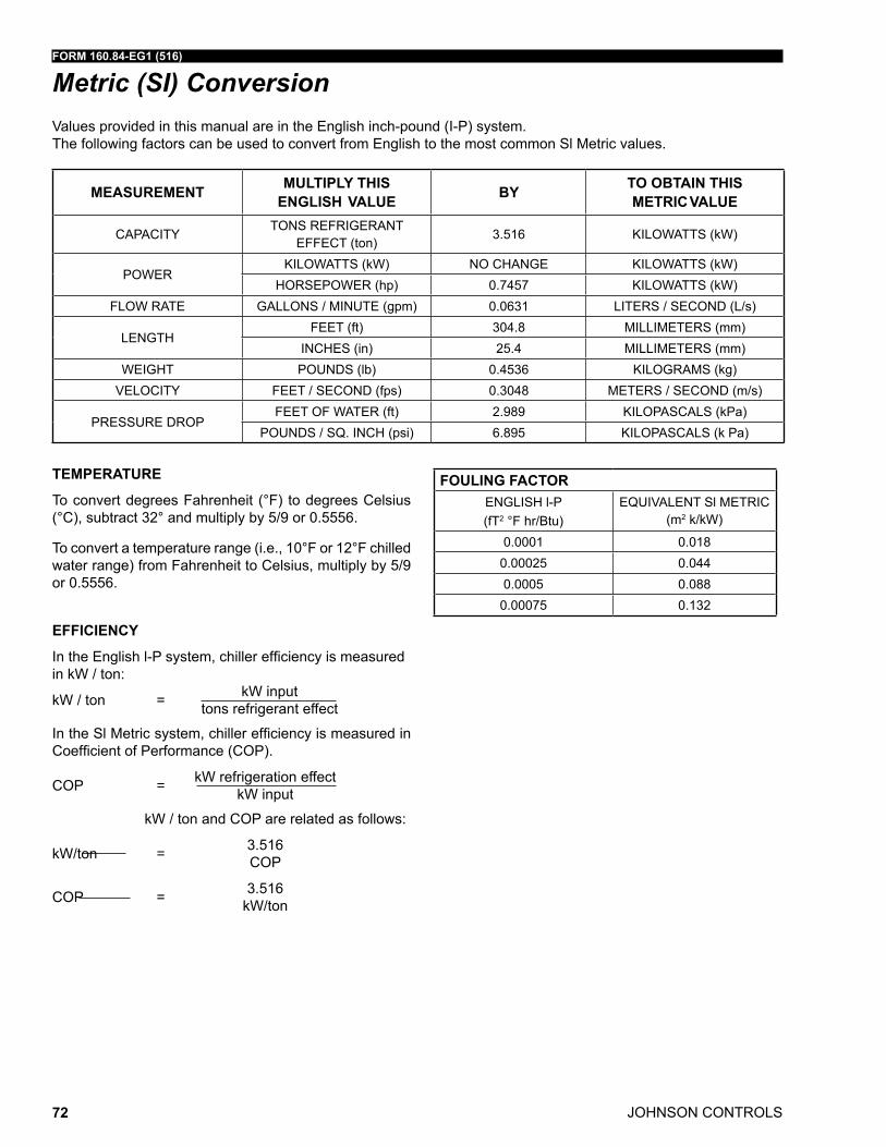
JOHNSON CONTROLS
FORM 160.84-EG1 (516)
72
Values provided in this manual are in the English inch-pound (i-P) system. the following factors can be used to convert from English to the most common sl metric values.
TEMPERATURE
to convert degrees fahrenheit (°f) to degrees Celsius (°C), subtract 32° and multiply by 5/9 or 0.5556.
to convert a temperature range (i.e., 10°f or 12°f chilled water range) from fahrenheit to Celsius, multiply by 5/9 or 0.5556.
EFFICIENCy
IntheEnglishl-Psystem,chillerefficiencyismeasuredin kW / ton:
kW / ton = kW input tons refrigerant effect
IntheSlMetricsystem,chillerefficiencyismeasuredinCoefficientofPerformance(COP).
CoP = kW refrigeration effect kW input
kW / ton and CoP are related as follows:
kW/ton = 3.516 CoP
CoP = 3.516 kW/ton
Metric (SI) Conversion
MEASUREMENT MULTIPLy THISENGLISH VALUE By TO OBTAIN THIS
METRIC VALUE
CaPaCitYtons rEfriGErant
EffECt (ton)3.516 KiloWatts (kW)
PoWErKiloWatts (kW) no ChanGE KiloWatts (kW)
horsEPoWEr (hp) 0.7457 KiloWatts (kW)floW ratE Gallons / minutE (gpm) 0.0631 litErs / sECond (l/s)
lEnGthfEEt (ft) 304.8 millimEtErs (mm)
inChEs (in) 25.4 millimEtErs (mm)WEiGht Pounds (lb) 0.4536 KiloGrams (kg)
VEloCitY fEEt / sECond (fps) 0.3048 mEtErs / sECond (m/s)
PrEssurE droPfEEt of WatEr (ft) 2.989 KiloPasCals (kPa)
Pounds / sq. inCh (psi) 6.895 KiloPasCals (k Pa)
FOULING FACTOREnGlish l-P(ft2 °f hr/Btu)
EquiValEnt sl mEtriC (m2 k/kW)
0.0001 0.0180.00025 0.0440.0005 0.088
0.00075 0.132
FORM 160.84-EG1 (516)
JOHNSON CONTROLS 73
Notes

Printed on recycled paperform 160.84-EG1 (516) supersedes: 160.84-EG1 (715) © 2016 Johnson Controls, inc. P.o. Box 423, milwaukee, Wi 53201 Printed in usawww.johnsoncontrols.comissued on 5/24/2016