model test coverage measurements in an industry setting · model test coverage measurements in an...
TRANSCRIPT

Model Test CoverageMeasurements in an Industry
Setting
Xiaowei Ma
July 8, 2013Master’s Thesis in Computer Science, 30 credits
Supervisor: Eduard Paul EnoiuExaminer: Daniel Sundmark
Malardalen UniversitySchool of Innovation, Design and Engineering
721 23 VasterasSweden


Abstract
Test coverage (e.g., statement, branch or condition-type coverage like MC/DC) is typicallymeasured with respect to source code when performing unit testing. However, in the case ofmodel-driven development, particularly in cases where state-based or similar models out ofwhich code is automatically generated constitute the de facto means of implementation, it isvaluable to be able to measure test coverage on this more abstract level of implementation.Recent results from model-driven development in the aviation industry have shown thatthere is not always a 100% compliance between the coverage attained by the same test suitewhen measuring at the model level, as compared to when measuring at the code generatedfrom the aforementioned model. In some cases (such as statement coverage), the reasons forthis are obvious. However, considering logic-based coverage criteria, such as MC/DC, thereasons are less intuitive, even to the point that they may suggest that some test suites thatyield 100% coverage on model-level are not fully adequate when considering the behavior ofthe generated code.
We propose a MSc Thesis with a threefold objective: (1) to facilitate the measurementof coverage on the model level, (2) to investigate the difference in coverage when measuredat the model- and the code levels, and (3) to see if any mechanism can be added on themodel-level to ensure adequate testing even with respect to code-level coverage.


Acknowledgements
This thesis could not have been done without the great support of my examiner DanielSundmark and my supervisor Eduard Paul Enoiu. Thank you for your patience, knowledge,experience, and willingness to help me.
I am very thankful to Robert, David, Dimitris,Rasul and many more for the great timewe have spent together during my stay in Vasteras.
Last but not least, I would like to thank my wife and my parents for their enduringsupport.
Vasteras, June 2013

ii

Contents
1 Introduction 1
1.1 Problem Description . . . . . . . . . . . . . . . . . . . . . . . . . . . . . . . . 1
1.2 Model Driven Development Overview . . . . . . . . . . . . . . . . . . . . . . 2
2 Background 5
2.1 Logic-based Coverage Criteria PC, CC and CACC . . . . . . . . . . . . . . . 5
2.2 Related Work . . . . . . . . . . . . . . . . . . . . . . . . . . . . . . . . . . . 9
3 MDD With Rational Rose RealTime 11
3.1 Rational Rose RealTime Overview . . . . . . . . . . . . . . . . . . . . . . . . 11
3.2 Logic Coverage of State Diagrams . . . . . . . . . . . . . . . . . . . . . . . . 14
3.3 RoseRT Transformation Rules for Transitions . . . . . . . . . . . . . . . . . . 16
4 Experimental design 23
4.1 Experiment Object . . . . . . . . . . . . . . . . . . . . . . . . . . . . . . . . 23
4.2 Procedure and Tools . . . . . . . . . . . . . . . . . . . . . . . . . . . . . . . . 24
5 Experimental Results and Analysis 27
5.1 Data Analysis . . . . . . . . . . . . . . . . . . . . . . . . . . . . . . . . . . . . 27
5.2 Source of Gap in Test Artifacts . . . . . . . . . . . . . . . . . . . . . . . . . . 30
5.3 Test Coverage Comparison Between Model and Code Level . . . . . . . . . . 32
6 Conclusion And Future Work 39
iii

iv CONTENTS

List of Figures
3.1 RoseRT Views and Software Development Lifecycle . . . . . . . . . . . . . . 12
3.2 Trigger and Guard Condition . . . . . . . . . . . . . . . . . . . . . . . . . . . 13
3.3 Action Code Attached to Transition . . . . . . . . . . . . . . . . . . . . . . . 13
3.4 RoseRT state diagram for a simple booking system . . . . . . . . . . . . . . . 15
3.5 Example of direct transition . . . . . . . . . . . . . . . . . . . . . . . . . . . . 16
3.6 Example transition specification . . . . . . . . . . . . . . . . . . . . . . . . . . 17
3.7 Code Implementation for Transition chain32 allocateCrntiCfm. . . . . . . . . 18
3.8 Code Implementation for Function chain32 allocateCrntiCfm. . . . . . . . . . 18
3.9 Transformation of Direct Transition. . . . . . . . . . . . . . . . . . . . . . . . 19
3.10 Example of indirect transition . . . . . . . . . . . . . . . . . . . . . . . . . . . 19
3.11 Code Implementation for Trigger of Transition watSpConfCfm. . . . . . . . . 20
3.12 Code Implementation for Chains of Choice Points. . . . . . . . . . . . . . . . 21
3.13 Transformation of Indirect Transition . . . . . . . . . . . . . . . . . . . . . . 21
4.1 Schematic view of the experimental setup . . . . . . . . . . . . . . . . . . . . 25
5.1 RoseRT Initial Point Example . . . . . . . . . . . . . . . . . . . . . . . . . . . 30
5.2 Code Implementation for Example Initial Point. . . . . . . . . . . . . . . . . . 30
5.3 Code Implementation for Shared Port. . . . . . . . . . . . . . . . . . . . . . . 31
5.4 Predicate Coverage Comparison in S1 . . . . . . . . . . . . . . . . . . . . . . 34
5.5 Predicate Coverage Comparison in S6 . . . . . . . . . . . . . . . . . . . . . . 35
5.6 Predicate Coverage Comparison in All Subsystems . . . . . . . . . . . . . . . 36
v

vi LIST OF FIGURES

List of Tables
2.1 Truth table for predicate p . . . . . . . . . . . . . . . . . . . . . . . . . . . . 8
2.2 Choices for CACC TR . . . . . . . . . . . . . . . . . . . . . . . . . . . . . . . 8
3.1 Predicates from simple booking system diagram . . . . . . . . . . . . . . . . . 15
4.1 Summary of experimental subject . . . . . . . . . . . . . . . . . . . . . . . . . 24
5.1 Number of test artifacts in RoseRT model vs C++ implementation. . . . . . 28
5.2 Composition of Predicates . . . . . . . . . . . . . . . . . . . . . . . . . . . . . 28
5.3 Impact on test requirements for logic-based criteria. . . . . . . . . . . . . . . 29
5.4 Predicate Coverage Comparison in S1 . . . . . . . . . . . . . . . . . . . . . . 33
vii

viii LIST OF TABLES

Chapter 1
Introduction
Software testing is becoming increasingly important for software development, as the resultof constantly pursuing higher quality of software products. Accordingly, various testingtechniques are introduced to software industry. As the increasing attention of Model-DrivenDevelopment (MDD), there are more and more discussions about how the testing processand techniques can be adapted to an MDD environment. Straeten et al. [1] summarized aseries of presentations held on MoDELS’08 conference and raised some challenges for MDD.As stated by them, in the context of MDD, it imposes a number of additional challenges,one of which is how to verify, validate, debug, and test the models and the code generatedfrom those models. Compared to testing the models, techniques of testing the generatedcode may be more commonly known. However, as the development of model-based testingapproaches and tools, there are more testing techniques that target design models as testingartifacts (e.g. [2]). Hence, how to test models and code become less of a problem, instead,more attentions have been paid to the correlation between mode level and code level testin terms of coverage level. The next section will describe the problem and our objectives,followed by an overview of Model-Driven Development.
1.1 Problem Description
There are regulations [19] specifying that test for safety critical software in avionics must bedesigned based on specifications, besides, structural test like Modified Condition DecisionCoverage (MCDC) [20] needs to achieve 100% coverage on code level. Thus, if full structuralcode coverage is not met, additional tests must be designed based on the specifications onmodel level, but not directly based on the code implementation. Whereas tests on modellevel designed for the specifications normally tend to be centered on functional testing, thiscan not guarantee that the additional tests will fill the gap of structural coverage on codelevel. Consequently, much more efforts will be paid to redesign additional tests from modellevel in order to meet the code level coverage requirement until it reaches 100%. In anMDD context, one solution is to have structural test taken into account on model level aswell, since the code is generated from the model there is possibility that the structure ofthe code is consistent with the structure of the model. Whereas the consistency needs tobe verified, and it can be reflected to the correlation between test coverage on model andcode level. If the structural coverage on model level is totally in accordance with code level,then the structural test on model that achieves 100% coverage will have good chance toachieve 100% coverage on code level. On the contrary, if there is no strong correlation of
1

2 Chapter 1. Introduction
structural coverage between the two levels, it still requires to iterate the process of designfrom model level and aim for code level. Thus, whether the solution works depends on ifthere are structural test coverage gaps between the two levels.
Model transformation is known as a key role in an MDD environment. One of thegoals that model transformation intends to achieve is generating lower-level models, andeventually code, from higher-level models [8]. Whereas, one question is how to preservethe structure of the models and ensure they are consistent throughout the transformationprocess. As the concern raised by Kirner [9] , when using model-based testing in an MDDenvironment, there is the question of whether the structural code coverage achieved at theoriginal program representation is also fulfilled at the transformed program representation.It is the code generator, also known as model compiler, that responsible for the transforma-tion. The way it transforms is so flexible that the only constraint is the transformed programcomputes the same results as the original program specification. Thus, after model-to-codetransformation, the structure of the generated code could be differed from the original model,depending on the techniques used by the model compiler and the programming language ofthe target source code. The differed structure could further result in structural test coveragegap between model and code level, as structural test for the model and the code will targetdiagrams and generated code respectively as testing artifacts.
The main objectives of this thesis encompasses:
– 1. Investigate the impact of model-to-code transformation on the test artifacts on bothmodel and code level. In an MDD context after the model-to-code transformation ifthe structure of the code are differed from the structure of model, the number of testartifacts could change accordingly.
– 2. Based on the logic-based coverage criteria, measure the test coverage for model andcode level respectively.
– 3. Locate the source that causes the test coverage gap between model and code level.
1.2 Model Driven Development Overview
In the early phase of a software project, high-level requirements will be defined and handedover to development team. With the old traditional development techniques, there mostpossibly are two options for the development team to proceed. One is to take time to definesolutions in the beginning without yielding software artifacts. The other is to go directly tofocus on code implementation for the requirements without structuring the overall solution.Either option could pose risks to the project, for example the former may increase thetime to market, the later may increase difficulties in future maintenance. Model-DrivenDevelopment (MDD) approach is another option which focuses on the use of models oneach level of the software development process. In an MDD context, models can be usedto represent different aspects of a system at all levels, such as requirements and designspecifications and so forth.
Model-Driven Architecture (MDA) [4, 10] is a typical model-driven software developmentapproach which was launched by the Object Management Group (OMG) in 2001. A commonMDA paradigm starts with defining a platform independent model (PIM), which is followedby manually or automatically translating it to one or more platform-specific models (PSM),and ends with a code generation from PSMs. PIM is used to define formal high-levelspecifications of the structure and functions of a system, and it abstracts away technicaldetails, while PSM is used to specify the realization of the functionality defined in the

1.2. Model Driven Development Overview 3
PIM on a target platform that can run PSM. Both PIM and PSM are typically expressedin Unified Modeling Language (UML) [11], which is one of the core standards in MDA.Extensions to UML such as Executable UML [7] could also be used for translation of PIMinto PSMs.
The translation from PIM to PSMs as well as the code generation from PSM couldbe time-consuming, error-prone and of poor efficiency if they are all done by hand. Asstated by Czarnecki et al [12] ”The MDA approach promises a number of benefits includingimproved portability due to separating the application knowledge from the mapping to aspecific implementation technology, increased productivity due to automating the mapping,improved quality due to reuse of well proven patterns and best practices in the mapping, andimproved maintainability due to better separation of concerns and better consistency andtraceability between models and code.” In order to achieve these benefits, it is imperative tohave an automatable way of ensuring the models are consistent throughout the translation,and model transformation does the job. Therefore, model transformation is believed toplay a key role in Model-Driven Development. Model transformation encompasses not onlymodel-to-model transformation but also code generation from PSM. As summarized byCzarnecki et al [13], code generation falls into the category of model-to-text transformationapproach.
One goal of MDA approach intend to achieve is to make the high-level models executableand testable, so that faults can be discovered and eliminated at early phase, given thatdesign and requirement faults found at implementation phase will be expensive to correct.However, the way of testing in MDA may be different from in the traditional developmentapproach. In MDA, the use of UML models introduces varieties of UML diagrams such asstate machine diagrams, use-case diagrams, sequence diagrams, etc. All these diagrams aretangible software artifacts from which the test cases can be derived. Thus in MDA, as thechange of the way software systems are built, the software artifacts under test, as well asthe way they are tested will also be changed. However, there are possibilities that the samecoverage criteria used on source code can also be applied to software artifacts on modellevel. Take structural test for example, in a traditional development approach it tends tofocus on coverage analysis for code implementation based on related coverage criteria, suchas logic-based coverage criteria. To some extent, the structure of the executable models inMDA can also be examined by logic-based coverage criteria.There are more details aboutlogic-based coverage in Section 2.1.
A test process which is modeled with MDA approach is called Model-Based Testing(MBT). It also aims to test the system at early phase of the development process, thusMBT techniques are recommended to be used in MDA, though the testing object of MBTcan be independent of MDA. MBT provides techniques for the automatic generation oftest cases using models extracted from software artifacts [14]. It is believed that the MBTapproaches are in line with MDA in terms of favor models over code. One benefit of usingMBT techniques in MDA is that since there are already existing software artifacts after theuse of models at each level, efforts of extracting test models from software artifacts in MBTcan be saved. Mussa et al. [15] summarized 15 model-based testing approaches, however,the adoption of MBT by software industry remains low and signs of the anticipated researchbreakthrough are weak [16].

4 Chapter 1. Introduction

Chapter 2
Background
Since the main purpose of our study is to investigate the correlation between test coverageon model and code level, it is necessary to select proper coverage criteria that are applicableto test artifacts on both model and code level, which in our case are state diagrams andC++ code. For example, data flow criteria can be used to measure the test coverage forC++ code, however they are not so applicable to state diagrams.Thus it will be difficult tocompare the model coverage to code coverage with data flow criteria. Given that logic-basedcoverage criteria are commonly used for structural test for source code, and it also appliesto test for state diagrams, they are suitable to be used to measures the test coverage gapbetween model and code level. In this chapter an overview of the used logic-based coveragecriteria in our study will be presented, followed by an introduction of related work performedby other’s previous study.
2.1 Logic-based Coverage Criteria PC, CC and CACC
Ammann and Offutt in their book Introduction to Software Testing [3] state that, almost alltesting techniques could be characterized into a small number of abstract models: graphs,logical expressions, input domain characterizations, and syntactic descriptions. For eachof the four models, there are related coverage criteria that can be used by testers as basisto select a set of test cases. Thus, test data generation could be simplified into two steps.First abstract the target software artifact into one of the four models, and then designtest input based on related coverage criteria that are applicable to the abstracted model.The use of logic-based criteria, among the four kinds of models, may be more of commonsense and essential knowledge for most of the software developers, especially in avionicsindustry. One reason is that logical expression can easily be derived from almost all kindsof software artifacts, such as source code, modeling diagrams, and function specificationsand so on. Another reason for their growing use in practice is that some of the logic-based coverage criteria are incorporated in standards. For instance, Modified ConditionDecision Coverage (MCDC) [20] is required by the US Federal Aviation Administration(FAA) for certification of safety critical software in commercial aircraft. In this sectionwe mainly introduce three commonly used logic-based coverage criteria, namely PredicateCoverage(PC), Clause Coverage(CC) and Correlated Active Clause Coverage(CACC), aswell as their use in practice with examples.
Among the existing logic-based coverage criteria, there are many actually means thesame but with different terminology. Also, some versions of the coverage criteria, (e.g.,
5

6 Chapter 2. Background
MCDC) have some ambiguities. This often brings confusions to practitioners. In orderto eliminate the ambiguities and conflicting terminologies, Ammann et al. [21] abstractedrelated criteria with more precise definitions of various possibilities and formalized logicalexpressions in a common mathematical way. The criteria presented in this section are basedon their work.
A predicate is an expression that evaluates to a boolean value, and is the element withtopmost structure in a logical expression. A predicate consists of one or more clauses.A clause is a predicate that does not contain any logical operators and can be one of thefollowing: a Boolean variable, non-Boolean variables that are compared with the comparatoroperators, or a call to a Boolean function. . For simplicity, we call a predicate that consistsof only one clause a single-clause predicate, a predicate that consists of more than one clausea multiple-clause predicate. A single-clause predicate itself is also a clause, and the clausesin a multiple-clause predicate are joined by logical operators. For example, p = (a < b ∧C) ∨ f(x) is a multiple-clause predicate that consists of three clauses: a relation expressiona < b, a Boolean variable C and a Boolean function call f(x), and it contains two logicaloperators. The most common logical operators in source code are negation (¬), and (∧)and or (∨). Other logical operators, implication (→), exclusive or (⊕) and equivalence (↔),are more common in specifications. Ammann et al. defined coverage criteria in terms oftest requirement, thus we need to know the definition of test requirements before relatedcoverage criteria are presented.
Definition 2.1.1. Test Requirement: A test requirement is a specific element of a softwareartifact that a test case must satisfy or cover. [3]
Clauses and predicates are used to introduce a variety of coverage criteria. Let P be aset of predicates and C be the set of clauses in the predicates in P. For each predicate p ∈P, let Cp be the set of clauses in p, that is, Cp = {c|c ∈ p}. C is the union of the clauses ineach predicate in P, that is, C = p ∈ P Cp.
Definition 2.1.2. Predicate Coverage (PC): For each p ∈ P, TR contains two requirements:p evaluates to true, and p evaluates to false. [21]
Predicate Coverage is equivalent to the edge coverage criterion which is used when agraph-based model can be abstracted from the software artifacts under test. In some litera-tures, it is also referred to as Decision Coverage [22]. For the example predicate given above,p = (a < b ∧ C) ∨ f(x), two test cases that can satisfy full predicate coverage are (a = 1, b= 2, C = true, f(x) = false) and (a = 3, b = 2, C = true, f(x) = false). Though predicatecoverage is satisfied by these two test cases, the clause C and f(x) are not exercised. Thus,one insufficient factor of predicate coverage is that not all the individual clauses will alwaysbe covered. To overcome this insufficiency clause level coverage needs to be taken care of.
Definition 2.1.3. Clause Coverage (CC): For each c ∈ C , TR contains two requirements:c evaluates to true, and c evaluates to false. [21]
In some literatures Clause Coverage is also referred to as Condition Coverage [22]. Ac-cording to the definition, in order to satisfy clause coverage for the same predicate p = (a< b ∧ C)∨ f(x), each of the clauses a < b, C, and f(x) needs to be evaluated to trueand false respectively. Thus, two test cases (a = 1, b = 2, C = true, f(x) = false) and(a = 3, b = 2, C = false, f(x) = true) will be sufficient to satisfy CC. As presented, thetwo test cases that satisfy predicate coverage can not guarantee clause coverage. Likewise,the two test cases that satisfy clause coverage can not guarantee predicate coverage either.Thus, clause coverage does not subsume predicate coverage, and predicate coverage does

2.1. Logic-based Coverage Criteria PC, CC and CACC 7
not subsume clause coverage. This brings inconvenience to testers, especially when testsare designed aiming for clause coverage, the effect on predicate coverage is also desired. Inorder to achieve this, coverage on a deeper level like Active Clause Coverage is introduced.
Definition 2.1.4. Active Clause Coverage (ACC): For each p ∈ P and each major clauseci ∈ Cp , choose minor clauses cj , j 6= i so that ci determines p. TR has two requirementsfor each ci : ci evaluates to true and ci evaluates to false. [21]
ACC is fundamentally the same as MCDC, while MCDC may have some ambiguitiesin terms of how it is interpreted. An identifier to distinguish the different interpretationsfrom each other is whether the minor clauses cj need to have the same values when themajor clause ci cause p true as when ci cause p false. To more precisely match ACCto MDCD, Ammann et al.[21] introduced three flavors of ACC, General Active ClauseCoverage,(GACC) Correlated Active Clause Coverage (CACC) and Restricted Active ClauseCoverage (RACC). GACC allows the minor clauses to have different values, and it does notsubsume Predicate Coverage. The version of MCDC commonly called ”masking MCDC”[23] is equivalent to CACC. The original definition of MCDC [20], sometimes also referred toas ”unique cause MCDC”, corresponds to RACC. Since CACC is relevant to our experiment,an example of CACC will be presented.
Definition 2.1.5. Correlated Active Clause Coverage (CACC): For each p ∈ P and eachmajor clause ci ∈ Cp, choose minor clauses cj , j 6= i so that ci determines p (ci is active).TR has two requirements for each ci: ci evaluates to true and ci evaluates to false. Thevalues chosen for the minor clauses cj must cause p to be true for one value of the majorclause ci and false for the other, that is, it is required that p(Ci = true) 6= p(Ci = false) .[21]
Consider the predicate p = ((a ∨ b) ∧ c) ∨ d, which consists of four clauses, a, b, c, andd. According to the definition of CACC, each of the clauses needs to be the major clauseonce and be evaluated to true and false respectively to cause the predicate shift betweentrue and false. This result in eight test requirements to achieve CACC, however some ofthem may overlap with each other. To show the specific test requirements, we present thefull truth table for the example predicatep = ((a ∨ b) ∧ c) ∨ d in Table 2.1. The truthvalues for each of the clauses as well as the whole predicate are listed. The columns Aa, Ab,Ac, Ad stand for if clause a, b, c and d is active. For example in entry 1, clause c determinesthe predicate, if c changes the value of the predicate will be changed accordingly, thus Ac
is active and set to T.First, in order to make clause a the major clause and the change of a will also cause
the change of the predicate, row 4 and 15 must be selected, since a is only active in thesetwo rows. With the same reason for clause b, row 7 and 15 must be selected. At thispoint the rows {4, 7, 15} are selected in order to cover clause a and b. In order to getclause c also covered, we simply need to select one entry from rows{12, 13, 14} to make ccause the predicate to be false, since row {4, 7} already can make c cause the predicate totrue. Hence, this result in three choices for minimal sets of rows,{4, 7, 15, 12}, {4, 7, 15, 13}or {4, 7, 15, 14} to cover clause a, b and c. The final step is to cover d, which only needsto select one entry from rows {2, 5, 8, 9, 10} to combine with any choice from {4, 7, 15, 12},{4, 7, 15, 13} or {4, 7, 15, 14}. Finally there are 15 choices for minimal set of rows to satisfyCACC for the example predicate, as shown in Table 2.2.
Ammann et al. stated that for a predicate with N independent clauses, it is sufficientto achieve ACC coverage with the maximum number of test requirements N+1, ratherthan 2N [21]. In a way, this is verified in our example predicate which consists of four

8 Chapter 2. Background
Table 2.1: Truth table for predicate p
Table 2.2: Choices for CACC TR

2.2. Related Work 9
independent clauses. For all the choices from Table 2.2, they all have 5 rows, which equalsto 4 + 1. As for Predicate Coverage, since it only requires the predicate to be evaluated totrue and false, in our case it can be achieved by the combination of any entry from rows{0, 1, 2, 3, 4, 5, 6, 7, 8, 9, 10} and any entry from rows {11, 12, 13, 14, 15}. Thus, only two testrequirements are sufficient to satisfy PC for a given predicate, regardless of how many theclauses it consists of. For Clause Coverage, each of the clauses needs to be evaluated to trueand false. However, the above mentioned overlap always happens. As shown in Table 2.1,any choice from the set of rows {0, 11}, {1, 10}, {2, 15} , {3, 14}, {4, 8}, {5, 7} , {6, 13} or{9, 12} can satisfy CC for the example predicate. Thus, two requirements are sufficient toachieve CC for a given predicate, also regardless of how many clauses it consists of.
It needs to be clarified that deeper level logic coverage criteria such as ACC and MCDCplay an important role only when the predicates consists of more than one clause. If apredicate only has one clause, all of the logic coverage criteria collapse into the same criteriaas Predicate Coverage and Clause Coverage.
2.2 Related Work
Baresel et al. [25] presented an empirical study that demonstrated the availability of struc-tural coverage criteria for models and investigated the correlation between structural modeland code coverage criteria. The study used a code generator called TargetLink [26] to trans-form Simulink / Stateflow [27, 28] models into C programming language code. With theuse of model coverage analysis tool, Model Coverage Tool [29], the authors first attainedthe test coverage on model level based on an initial test suite, and then with the aid of thetest system TESSY [30], test coverage for the same suite on code level was attained as well.After comparison, the authors found that a strong correlation between decision coverage onmodel level and branch coverage on code level. The strong correlation was further verifiedby the experiment result that as the additional test data were designed to improve the testcoverage on code level, not only the updated suite yielded higher test coverage on modellevel, but also the respective decision coverage and branch coverage on the two levels are veryclose. The strong correlation was present in all the three subsystems of their experiment.
Rajan et al. [31] also used Simulink models to perform a empirical study that investigatedthe effect of code and model structures on MCDC test adequacy criteria. The authors believethat MCDC is sensitive to the structure of the code implementation or models under test,thus they measured the test coverage on two different versions of implementations, namelynon-inline and inline implementations. In a non-inline implementation, additional variablesare introduced to factor complex Boolean expressions into simpler expressions which consistof at most one logical operator. The authors first measured the MCDC coverage on a non-inline implementation based on a test suite, and then used the test suite to measure theMCDC coverage again on an inline implementation, an average of 29.5% decrease in thecoverage were discovered. It was stated that the decrease was mainly caused by the factthat MC/DC measurement on non-inline implementation does not take the effect of masking[24] into account while measurement on inline implementation does. The authors believethat there is a serious need for coverage criteria that takes masking into account regardlessof the implementation structure, or as an alternative, a canonical way of structuring codeso that condition masking is revealed when measuring coverage in terms of related coveragecriteria.
Rajan et al. [31] studied the effect of different implementations on MCDC, while Erikssonet al. [5] presented an empirical study that investigated the effect of model transformationon the test artifacts, as well as the impact on the number of test requirements when trans-
10 Chapter 2. Background
forming a platform independent design model to code. Their study used six applicationsof aviation system software developed in xtUML[7] models, which were further transformedinto C++ code by model compiler. The number of test artifacts (predicates and clauses)was counted before and after the model-to-coed transformation. Based on the number ofpredicates and clauses, the number of test requirements for various logic-based criteria wascalculated for each application. Their results showed that as the increase in the number oftest artifacts, the test requirements for logic-based coverage criteria such as CACC will beincreased accordingly.

Chapter 3
MDD With Rational RoseRealTime
In our study, an MDD environment is provided by our industrial partner who uses RationalRose RealTime to develop their systems. In the following of this chapter, an overview ofRational Rose RealTime will be presented, followed by introductions of how to derive logicalexpressions from RoseRT state diagrams and further apply logic-based coverage criteriato the diagrams. As mentioned in Section 1.1, after model-to-code transformation, thestructure of the code may be differed from the original model, RoseRT also supports codegeneration from models to code. Thus, at the end of this chapter there will be introductionsto transformation rules that translate transitions in a RoseRT diagram into C++ code.
3.1 Rational Rose RealTime Overview
Rational Rose RealTime is an MDD tool that is developed specifically to design com-plex, event-driven, and concurrent systems, based on Real-time object-oriented modeling(ROOM) methodology [17]. It can be used to create models of the software system basedon the UML constructs which can efficiently generate the implementation code, compile,and run and debug the application. Around 90% of the implementation code can be di-rectly generated from RoseRT models, and the rest of 10% needs to be manually writtenand attached to the models by developers. In Addition to UML construct, RoseRT alsoprovides constructs that are based on UML modeling elements and are specialized for cre-ating executable real-time models. Currently RoseRT supports the development of softwaresystems in C, C++, and JAVA.
A typical RoseRT development paradigm consists of four steps. Each step is taken un-der a view that can be aligned with a software lifecycle phase, shown in Figure 3.1. Thediagrams created under each view are the artifacts of the corresponding development phase.Use-Case View describes system (subsystem, class, or interface) functionality without speci-fying how the system internally performs its tasks. Logical View represents the architecturalprocesses as the model moves from analysis, through design, and into development. It de-scribes how system functionality is provided within the system. Static structure describedby class diagrams and dynamic behavior described by state, sequence, collaboration andactivity diagrams etc. mainly make up the logical view. Component View describes theimplementation modules and their dependencies, containing component and package dia-
11
12 Chapter 3. MDD With Rational Rose RealTime
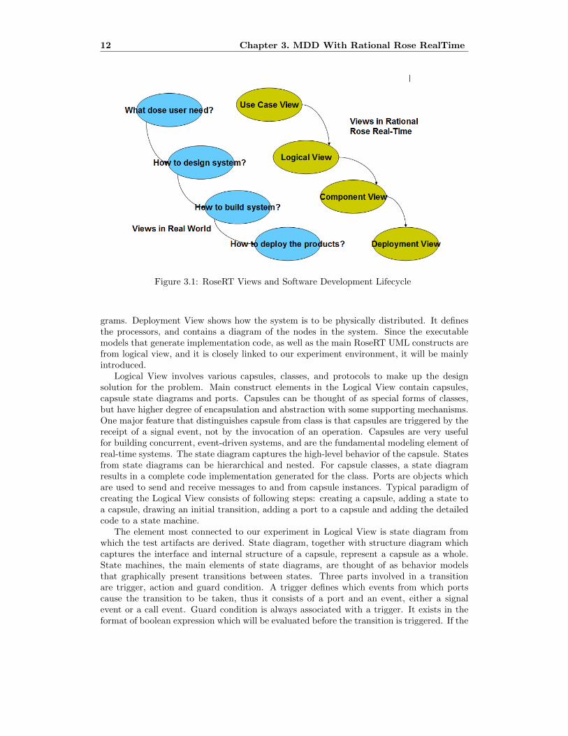
Figure 3.1: RoseRT Views and Software Development Lifecycle
grams. Deployment View shows how the system is to be physically distributed. It definesthe processors, and contains a diagram of the nodes in the system. Since the executablemodels that generate implementation code, as well as the main RoseRT UML constructs arefrom logical view, and it is closely linked to our experiment environment, it will be mainlyintroduced.
Logical View involves various capsules, classes, and protocols to make up the designsolution for the problem. Main construct elements in the Logical View contain capsules,capsule state diagrams and ports. Capsules can be thought of as special forms of classes,but have higher degree of encapsulation and abstraction with some supporting mechanisms.One major feature that distinguishes capsule from class is that capsules are triggered by thereceipt of a signal event, not by the invocation of an operation. Capsules are very usefulfor building concurrent, event-driven systems, and are the fundamental modeling element ofreal-time systems. The state diagram captures the high-level behavior of the capsule. Statesfrom state diagrams can be hierarchical and nested. For capsule classes, a state diagramresults in a complete code implementation generated for the class. Ports are objects whichare used to send and receive messages to and from capsule instances. Typical paradigm ofcreating the Logical View consists of following steps: creating a capsule, adding a state toa capsule, drawing an initial transition, adding a port to a capsule and adding the detailedcode to a state machine.
The element most connected to our experiment in Logical View is state diagram fromwhich the test artifacts are derived. State diagram, together with structure diagram whichcaptures the interface and internal structure of a capsule, represent a capsule as a whole.State machines, the main elements of state diagrams, are thought of as behavior modelsthat graphically present transitions between states. Three parts involved in a transitionare trigger, action and guard condition. A trigger defines which events from which portscause the transition to be taken, thus it consists of a port and an event, either a signalevent or a call event. Guard condition is always associated with a trigger. It exists in theformat of boolean expression which will be evaluated before the transition is triggered. If the

3.1. Rational Rose RealTime Overview 13
Figure 3.2: Trigger and Guard Condition
Figure 3.3: Action Code Attached to Transition

14 Chapter 3. MDD With Rational Rose RealTime
expression evaluates to True, then this trigger will cause the transition to be fired, otherwisethe transition is not fired. The default value of a guard condition is true. As the exampleshown in Figure 3.2, a signal event and a port make up the trigger. A guard conditionevaluated to true are combined with the trigger, meaning trigger will be fired by the receiptof signal ”go” on port ”commandP”. Actions are the behaviors that are performed before atransition enters into next state. Typically in an action, a set of variables or attributes arecomputed written in a programming language. Actions can be attached to a transition anda state, either as an entry action or an exit action. As the example shown in Figure 3.3,an action with example code is attached to the transition. The code will be executed afterthe trigger is fired. A step further, after the action code is performed, the transition willcomplete by entering into state S2 from State S1. Note that in this example there are noactions attached to state. Most of the information about RoseRT presented above is basedon [18].
3.2 Logic Coverage of State Diagrams
The most common way to apply logic coverage criteria to state-based diagram is to considerthe trigger of a transition as a predicate, then derive the logical expressions from the trigger.Consider the example RoseRT model state diagram in Figure 3.4, which models the behaviorof a simple booking system. There are four states in the diagram, idle, findResource,waitingList and running. As mentioned in Section 3.1, a transition in RoseRT state diagramconsists of three parts, namely event message, port and guard condition. The event messageused is this example is signal event and the guard condition is true for all transitions, whichmeans the transitions will be triggered when the specified signals are received on the port.Thus, the logical expressions derived from the triggers all consist of at least two clauses, aport and a signal.
As presented in Table 3.1, in all there are nine transitions in the diagram, the initialtransition is not included in the table. In RoseRT model, the initial transition is triggeredwhen the object is constructed. For simplicity, one public port is designed to be shared byall the signals, which explains why all the predicates have the same port in the table. Itneeds to be clear that if a guard is false, then the predicate will be negative. Take transition6 for example, if the guard is false, the predicate should be ¬ (port ∧ quitList). Thepredicates of transition 1,2,3,4 and 5 consist of not only a port and a signal but also otherconditions, that is because after these transitions are triggered they also go through choicepoints. A choice point allows a single transition to be split into two outgoing transitionsegments, each of which can terminate on a different state, depending on the truth valueof the condition. Therefore going through one choice point will add one more clause to thepredicate. Transition 4 and 5 go through two choice points, thus their predicates consist oftwo more clauses based on the signal and port, namely totally 4 clauses. One thing needs tobe clarified is that all the clauses of the eight predicates are joined by the logical operator ∧”AND” , since by semantical translation, all the clauses of a predicate need to be satisfied,if any of the clauses is not satisfied the transition will not be taken.
After the predicates are derived, logic-based coverage criteria such as PC, CC and CACCcan be applied. To satisfy PC and CC for the 8 predicates, 16 test requirements are sufficientsince it needs only two test requirements for each predicate. As summarized in Section 2.1,for a predicate with N independent clauses, it is sufficient to achieve CACC coverage withthe maximum number of test requirements N+1. Therefore, to satisfy CACC, transition 1,2 and 3 need 4 TRs for each, transition 4 and 5 need 5 TRs and transition 6, 7 and 8 need3 TRs. All the logical operators in the predicates are ∧ ”AND”, this makes it easy to select

3.2. Logic Coverage of State Diagrams 15
Figure 3.4: RoseRT state diagram for a simple booking system
Table 3.1: Predicates from simple booking system diagram

16 Chapter 3. MDD With Rational Rose RealTime
Figure 3.5: Example of direct transition
test input to satisfy the three mentioned criteria, particularly for CACC, since any clauseof the predicates can be active when the rest of the clauses are evaluated to true. It needsto be clear that in order to generate final executable test script there are a few more thingsneed to be taken care of. One is how to design the prefix of the test, since sometimes itrequires to enter into a specific state before the transition can be tested. For example, inorder to test transition 3, 4 and 5, it needs to be triggered from state findResource, whilestate findResource can either be reached from state idle or waitingList. Thus, extra worklike design of the prefix of the test data is needed.
3.3 RoseRT Transformation Rules for Transitions
From all the state diagrams we traversed, there are mainly two kinds of transitions thatcould be seen from RoseRT model. The first type is a direct transition that comprises onlyone step of action, like the example transition shown in figure 3.5, circled in green line. Thiskind of transition is triggered between two states that are located on the same level of themultiple layered state diagrams. The example transition starts from state waitCmti to statewaitAddUe. They are on the same level, and both are the sub-states of another state fromupper layer.
The specification of the example transition is shown in below Figure 3.6. As describedin the transition specification, on model level, the predicate for this transition in naturelanguage is that signal allocateCrntiCfm is received on port rnhIfCellControlP, which couldbe interpreted as the predicate comprises two clauses, namely port rnhIfCellControlP andsignal allocateCrntiCfm. And this rule applies to all the direct transitions since all thetriggers share the same pattern, that is, a given signal sent on a specified port. In any case,a port name and a message signal name make up the trigger for a transition. Though in

3.3. RoseRT Transformation Rules for Transitions 17
Figure 3.6: Example transition specification
real implementation, a signal is unique, which makes the combination of a port and a signalalso unique, regardless of the signal is sent on which port. In this sense, the trigger of thetransition could also be treated as a predicate that comprises only one clause, namely, thecombination of the signal and the port. However, in theory a signal is not necessarily uniqueto all ports. Therefore, the signal and port are still thought of as two separate clauses thatconstitute a predicate for a trigger.
After the model-to-code transformation, this example transition is interpreted as codefragment shown in Figure 3.7 which is extracted from the corresponding C++ file. The trig-ger is represented by a nested switch statement. The outer switch statement is used to repre-sent the port, and the internal switch statement is used to represent the signal. Each case ofone switch statement is thought of as a predicate. As seen in the commented part of the code,port 3 stands for rnhIfCellControlP , and RnhIfCellControlP::Base::rti allocateCrntiCfmmeans signal allocateCrntiCfm is received. Attention needs to be paid that under the switchstatement of port 3 (rnhIfCellControlP), there is another case for signal rti allocateCrntiRej,which does not add any predicate to the example transition, because this is another triggerfor another transition, and it merely shares the same port as the example transition. Therewill be more details with respect to the impact on the number of predicates and clausescaused by shared port in Chapter 5.
Once the trigger of the example transition is satisfied, the function chain32 allocateCrntiCfmis called. As shown in below code fragment, Figure 3.8, function chain32 allocateCrntiCfmmakes the transition started and further calls transition32 allocateCrntiCfm which is a man-ually added function. After that the transition is finished by entering into a new state. Notethat state waitCmti corresponds to state 5 in the code, and state waitAddUe correspondsto state 6. When the function chain32 allocateCrntiCfm is called, there are no statementssuch as if, switch, while or other statements that introduce extra predicates. According tothe definition of clause, it is obvious that the predicate that comprises two clauses for thetrigger in the state diagram is translated into two predicates, with each containing only oneclause in the C++ code.
For simplicity, assume that on the model level the predicate for the direct transition is “if

18 Chapter 3. MDD With Rational Rose RealTime
1 // {{{RME state ’:TOP:running:NewCell:waitCrnti’2 switch( portIndex )3 {4 case 0:5 switch( signalIndex )6 {7 case 1:8 return;9 default:
10 break;11 }12 break;13 case 3: //{{{RME classifier port ’rnhIfCellControlP’14 switch( signalIndex )15 {16 case RnhIfCellControlP::Base::rti_allocateCrntiCfm:17 chain32_allocateCrntiCfm();18 return;19 case RnhIfCellControlP::Base::rti_allocateCrntiRej:20 chain41_allocateCrntiRej();21 return;22 default:23 break;24 }25 break;26 // }}}RME27 default:28 break;29 }30 break;31 // }}}RME
Figure 3.7: Code Implementation for Transition chain32 allocateCrntiCfm.
1 INLINE_CHAINS void UehCellUpdateC_Actor::chain32_allocateCrntiCfm( void )2 {3 rtgChainBegin( 5, "allocateCrntiCfm" );4 exitState( rtg_parent_state );5 rtgTransitionBegin();6 transition32_allocateCrntiCfm((constRnhIfCellAllocateRntiCfmD*) \n7 msg->data,(RnhIfCellControlP::Base*)msg->sap());8 rtgTransitionEnd();9 enterState( 6 );
10 }11
Figure 3.8: Code Implementation for Function chain32 allocateCrntiCfm.

3.3. RoseRT Transformation Rules for Transitions 19
1 if A2 if B3 ...
Figure 3.9: Transformation of Direct Transition.
Figure 3.10: Example of indirect transition
A &&B”, what the transformation rule does is translating “if A &&B” into code fragmentshown in Figure 3.9.
Different from the first type of transition, the second one, indirect transition, containsat least two steps of transition chains and normally goes through at least one choice point.As the example shown in Figure 3.10, a transition from state watSpConfCfm to waitSpc ismarked in green lines. Along with the green line, there are in all four steps of sub-transition.The first step is designed to trigger the whole transition path, and it shares the same patternas the direct transition, namely a signal is sent on a port. After the trigger is satisfied, theexample transition goes through three choice points. Each of the rest of the three steps isa verdict result from a choice point. The example transition will be achieved only on thecondition that every step is satisfied. To be more specifically, the condition is: the trigger isfulfilled, and the verdict result of choice point SPFlagok2 is true, and the verdict result ofchoice point isUeRrcBarred is true, and the verdict result of choice point SpContBagBuildOkis true. Hence, the predicate for the example transition can be expressed by “signal ∧ port∧ SPFlagok2 =true ∧ sUeRrcBarred=true ∧ SpContBagBuildOk=true”, consisting of fiveclauses. From the perspective of the composition of a predicate, it is evident that eachchoice point will introduce one more clause to an indirect transition.
This example transition is expressed in code fragment shown in Figure 3.11 which isextracted from the corresponding C++ file after the model-to-cede transformation. Thefirst step of the transition path, namely the trigger, is represented with a nested switchstatement. Same as the way direct transition is interpreted, the outer switch statement

20 Chapter 3. MDD With Rational Rose RealTime
1 // {{{RME state ’:TOP:running:NewCell:waitSpConfCfm’2 switch( portIndex )3 {4 case 0:5 switch( signalIndex )6 {7 case 1:8 return;9 default:
10 break;11 }12 break;13 case 8:14 // {{{RME classifier ’Logical View’ port ’dcsIfControlP’15 switch( signalIndex )16 {17 case DcsIfControlP::Base::rti_spConfigCfm:18 chain34_spConfCfm();19 return;20 case DcsIfControlP::Base::rti_spConfigRej:21 chain44_spConfRej();22 return;23 default:24 break;25 }26 break;27 // }}}RME
Figure 3.11: Code Implementation for Trigger of Transition watSpConfCfm.
is used to represent the port, and the internal switch statement is used to represent thesignal. Each case of one switch statement is thought of as a predicate. Thus, the triggerstill introduces two clauses to the predicate of the transition. As shown in the commentedpart, the two clauses are port 8 (dcsIfControlP) and signal spConfigCfm.
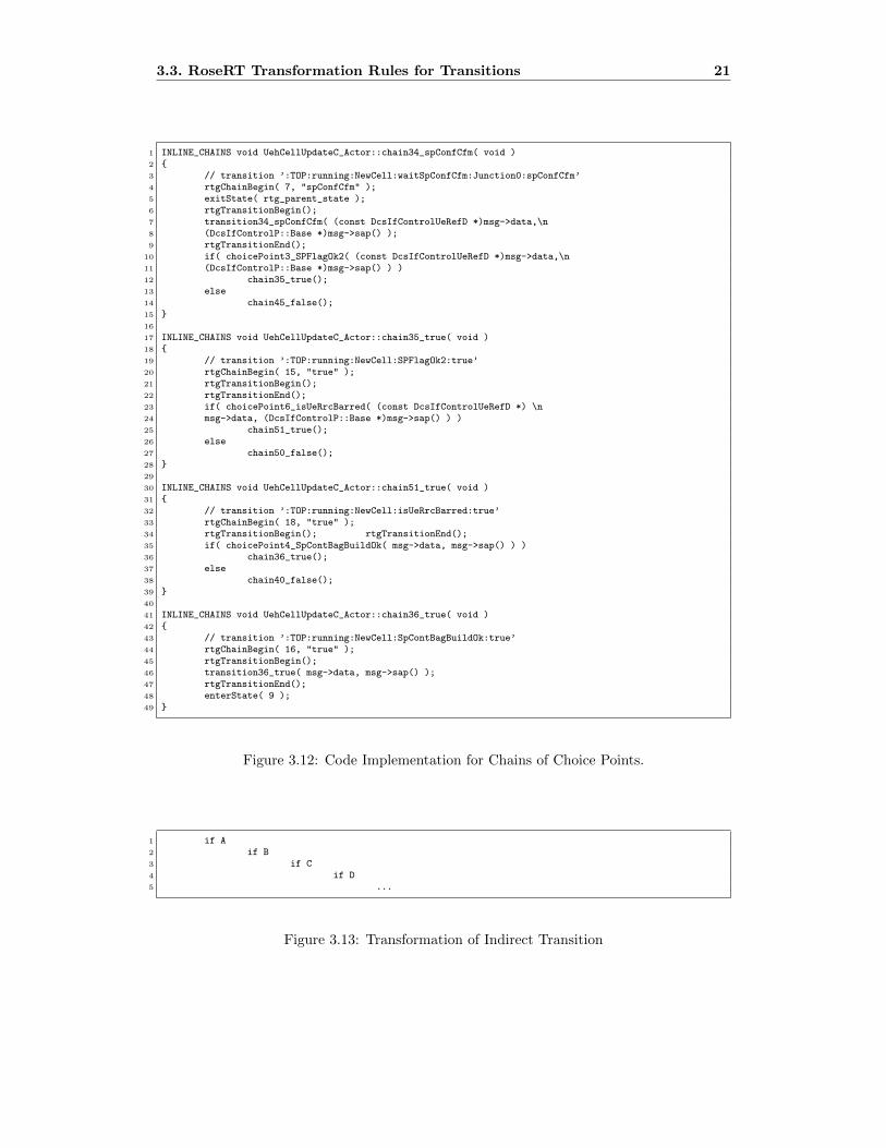
Once the trigger is the fulfilled the function chain34 spConfCfm will be called. Fromcode fragment, Figure 3.12 , it can be seen that function chain34 spConfCfm will makea verdict for choice point SPFlagOk2 by a if statement, the example transition path willgo through the case of true and further call function chain 35true. Similarly, chain 35truewill make a verdict for the second choice point, isUeRrcBarred, by another if statement.Again, the case of true will be taken to go along the example transition path, and thenchain51 true will be called. Chain51 true again will make a verdict for the third choicepoint, SpContBagBuildOk, also by a new if statement. The case of true once again will betaken and chain36 true will be called and no extra if statement will be used for choice pointat this time. Finally, the transition will be finished by entering into state 9, namely waitSpc.
The whole process of an indirect transition is translated into nested if statements. Eachchoice point corresponds to one if statement, and itself then will be wrapped up in an upperlayer if statement. Each layer of if statement consists of only two cases, namely either tobe evaluated to true or false. From the perspective of predicate and clause, this means thatafter the model-to-code transformation, unlike the model level, there will be no predicatethat consists of more than one clause on code level. In other word, each single clause thatconstitutes a predicate on model level will be transformed into a predicate that consists ofonly single clause on code level. For example, if the predicate for a transition on modellevel is “if A&&B&&C&&D”, then it will be transformed into the code fragment shown inFigure 3.13.
Attention needs to be paid that there might be more than one transition path betweentwo states. For example in Figure 3.10, between state watSpConfCfm and state waitSpc,
3.3. RoseRT Transformation Rules for Transitions 21
1 INLINE_CHAINS void UehCellUpdateC_Actor::chain34_spConfCfm( void )2 {3 // transition ’:TOP:running:NewCell:waitSpConfCfm:Junction0:spConfCfm’4 rtgChainBegin( 7, "spConfCfm" );5 exitState( rtg_parent_state );6 rtgTransitionBegin();7 transition34_spConfCfm( (const DcsIfControlUeRefD *)msg->data,\n8 (DcsIfControlP::Base *)msg->sap() );9 rtgTransitionEnd();
10 if( choicePoint3_SPFlagOk2( (const DcsIfControlUeRefD *)msg->data,\n11 (DcsIfControlP::Base *)msg->sap() ) )12 chain35_true();13 else14 chain45_false();15 }16
17 INLINE_CHAINS void UehCellUpdateC_Actor::chain35_true( void )18 {19 // transition ’:TOP:running:NewCell:SPFlagOk2:true’20 rtgChainBegin( 15, "true" );21 rtgTransitionBegin();22 rtgTransitionEnd();23 if( choicePoint6_isUeRrcBarred( (const DcsIfControlUeRefD *) \n24 msg->data, (DcsIfControlP::Base *)msg->sap() ) )25 chain51_true();26 else27 chain50_false();28 }29
30 INLINE_CHAINS void UehCellUpdateC_Actor::chain51_true( void )31 {32 // transition ’:TOP:running:NewCell:isUeRrcBarred:true’33 rtgChainBegin( 18, "true" );34 rtgTransitionBegin(); rtgTransitionEnd();35 if( choicePoint4_SpContBagBuildOk( msg->data, msg->sap() ) )36 chain36_true();37 else38 chain40_false();39 }40
41 INLINE_CHAINS void UehCellUpdateC_Actor::chain36_true( void )42 {43 // transition ’:TOP:running:NewCell:SpContBagBuildOk:true’44 rtgChainBegin( 16, "true" );45 rtgTransitionBegin();46 transition36_true( msg->data, msg->sap() );47 rtgTransitionEnd();48 enterState( 9 );49 }
Figure 3.12: Code Implementation for Chains of Choice Points.
1 if A2 if B3 if C4 if D5 ...
Figure 3.13: Transformation of Indirect Transition

22 Chapter 3. MDD With Rational Rose RealTime
in addition to the example transition path marked in green line, another transition path isSPFlagok2=false ∧ SpContBagBuildOk=true. Though the two paths share the same trigger,the predicates of them are different. One predicate is “signal ∧ port ∧ SPFlagok2=true∧ isUeRrcBarred=true ∧ SpContBagBuildOk=true”, and the other is “signal ∧ port ∧SPFlagok2=false ∧ SpContBagBuildOk=true”. These two paths are considered as twodifferent transitions though they share the same start point and end point. Therefore, themeaning of transition in our study is not limited to state change. More precisely, it coversevery possible transition path between two states.

Chapter 4
Experimental design
The main target of our study is to investigate the correlation between code level test cov-erage and model level test coverage under an MDD environment. Firstly, an independentreplication of the experiment done by Eriksson et al. [5] has been performed in order toinvestigate how the number of test artifacts is affected by the model-to-code transformation.As stated by Eriksson et al., in their case, the transformation from model to code resultsin introducing more test artifacts (predicates and clauses) on code level. It is pointed outthat their results are limited to the specific models and tools used in their experiment. Ourexperiment has been performed using RoseRT models and corresponding generated C++files. Secondly, related logic coverage criteria have been applied to those test artifacts thatare derived from state diagrams on model level, and then we calculated the model leveltest coverage based on the total test requirements and actual tested artifacts, and finallycompared it with the code level test coverage that are obtained in a similar way.
4.1 Experiment Object
The subject used in our experiment is a radio network system software provided by ourindustrial partner. In all there are six subsystems which are developed with IBM RationalRose RealTime. Table 4.1 shows a summary of the six subsystems. As mentioned in Section3.1, capsules are the fundamental modeling element of real-time systems. A capsule can bethought of as a special form of class, with higher degree of encapsulation and abstractionthan class. The states in a capsule can be hierarchical and nested. The number of thestates in Table 4.1 includes all the states from every layer of the hierarchical state diagrams,meaning each sub-state is also thought of as an independent state. In our experiment allthe test artifacts (predicates and clauses) on model level are derived from these hierarchicalstate diagrams. The transition column from Table 4.1 shows the total number of transitionpaths between any two states in a subsystem, including all initial transitions. The numberof the transitions in a subsystem is ranged from 1116 of subsystem S1 to 39831 of S6, whichhappens to reflect the actual complexity of the subsystems. From the perspective of systemdesign, S6 and S3 are the most complex subsystems and the rest of the subsystems arerelatively less complex. The diversity of the complexity serves our experiment purpose wellsince we also want to observe if the same result will be present in all subsystems that havedifferent sizes.
23

24 Chapter 4. Experimental design
Table 4.1: Summary of experimental subject
4.2 Procedure and Tools
We started our experiment by trying to record the number of predicates and clauses that arederived from the state diagrams of the RoseRT models, by using graphical analysis tools.However, related tools for RoseRT models are very rare, and developing such tools will beextremely time consuming and also beyond the scope of our study. Another option is todevelop a tool that opens RoseRT model files in a textual format and parse all the transitionobjects of the models, and then to count the predicates and clauses that constitutes thetransition. After putting some efforts on parsing the models as text, it is found that thetransition informations in the file are not adequate enough to track an indirect transitionthat comprises many steps of sub-transitions, particularly when a transition starts from anested sub-state and goes through its upper layer state and finally enters into another statethat is also from its upper layer.
As explained in Section 3.3, the transformation from model to code conforms to somepre-defined patterns which are contained in the model transformation tool. These rulescan be determined deterministically which makes it suitable to track and recognize thetransitions on the model level in the C++ file. Therefore, it is possible to parse the C++file and record all the transition paths for both model and code level. Hence, in order toobtain the number of transitions on model level we actually parsed all the transition pathsin the C++ code and used the model transformation rules as a reference to our model leveltracing. Thus a tool called RoseRT Predicate Parser (RPP) that parses the C++ files wasdeveloped using Python programming language. The main function of the tool is to countall the predicates and clauses for code level and keep track of all possible transition pathsbetween two states for model level. It also records each step of a given transition path, andcounts the choice points on the path which can be used as basis to calculate the number ofpredicates and clauses for model level.
As shown in Figure 4.1, with the tool RPP, the entire procedure of our experiment canbe simplified into below three steps.
– Step 1. Run the tool RPP, the records of all the transition paths as well as their portand signal can be obtained from the C++ code, based on which the tool will generatethe output for code level by counting the predicates and clauses.
– Step 2. After the records of the transition paths are obtained, RPP can providestatistics about the steps of each transition, which will be used as one of the twoinputs to calculate the number of predicate and clauses on mode level. The otherinput is the transformation rules extracted from the model compiler.

4.2. Procedure and Tools 25
Figure 4.1: Schematic view of the experimental setup
– Step 3. Based on the result of Step2 and transformation rules explained in Section3.3, the final output for model level can be obtained by basic calculations.
It needs to be clarified that, different from the definition of a transition in RoseRT modelcompiler where each single step of a path is considered as a transition, we consider every pos-sible path between two states that does not go through another state as a transition. Thus,the tool used in our experiment, RoseRT Predicate Parser, searches all possible transitionpaths between two states, and records each step of the possible paths.

26 Chapter 4. Experimental design

Chapter 5
Experimental Results andAnalysis
As previously mentioned in Chapter 4, our experiment is a replication of the one performedby Eriksson et al. [5]. Similarly, the number of test artifacts (predicates and clauses), werecounted before and after the transformation of RoseRT models to C++ code. Based onthe number of predicates P and clauses C obtained from our experiment, the number oftest requirements was further calculated for each subsystem in terms of three logic-basedcriteria, namely Predicate Coverage criteria, Clause Coverage criteria and Correlated ActiveClause Coverage criteria. Compared to previous study [5], we share the same result in termsof the increase in the number of predicates, as well as the increase in test requirements foraforementioned logic-based criteria. However, there is no significant increase in the numberof clauses after the model-to-code transformation. Meanwhile, the source that causes theincrease in the number of predicates is different. Therefore, the focus of our data analysis willbe the source that causes the increase in the number of predicates and the reason why there isno increase in the number of clauses. Moreover, though there are increased test requirementson code level, a same test suite is possible to have the same test coverage between model andcode level. This is because that though the total test requirements are increased, the sametest suite also has a good chance of covering more test requirements. Hence, additional tothe analysis of test requirements, another assignment will be investigating if the model leveltest coverage is in accordance with code level test coverage with a given test suite.
5.1 Data Analysis
As summarized in Table 5.1, in each subsystem, there is enormous increase in the numberof predicates after the model-to-code transformation. However, this is not the case for thenumber of clauses. Only in subsystem S2, S4 and S5, there is a very slight increase in thenumber of clauses. In the rest of the subsystems, the number of the clauses is decreasing.In the two most complex subsystems S3 and S6, the decrease is especially obvious. FromTable 5.1 it can be seen that the number of clauses and predicates are the same on codelevel, which is caused by the transformation rules explained in Section 3.3, again that is,after transformation, in C++ implementation every predicate consists of only one singleclause, which makes the clause itself is a predicate. In short, predicate and clause means thesame after the model-to-code transformation in our experiment. Note that column “Code
27

28 Chapter 5. Experimental Results and Analysis
Table 5.1: Number of test artifacts in RoseRT model vs C++ implementation.
Table 5.2: Composition of Predicates
Level Infeasible clauses” from Table 5.1 stands for those clauses that cannot be satisfied oncode level. All these clauses are located in unreachable code of C++ implementation, andthere is no way to trigger these clauses from the perspective of test design. The numberof infeasible clauses is already included in Column “code level predicates” and “code levelclauses”. About these infeasible clauses we provide more explanations in Section 5.2.
Table 5.2 shows the composition of the predicates on both model and code level. Eachcell contains two numbers, of which the first is the number of test artifacts in the RoseRTmodel, and the second is the number of test artifacts in the C++ implementation. Thenumber of the test artifacts on code level is not the same as in Table 5.1, because theinfeasible predicates and clauses are excluded. It can be seen that on model level, there is nopredicates that consists of only one single clause. All predicates on model level consist of atleast two clauses, because it requires at least a signal and a port to trigger a transition. Whileonly in subsystem S3 and S6, there are predicates that consist of more than four clauses onmodel level. This is because there are more state diagrams in S3 and S6 containing moretransitions that go through more choice points. Again, there is no predicate that consistsof more than two clauses on code level since all predicates consist of single clause, whichmakes the logic-based test on code level very cheap and easy.
Table 5.3 shows the impact on the number of test requirements for related logic-basedcoverage criteria. As explained in Section 2.1, if the number of predicates P and clauses C are

5.1. Data Analysis 29
Table 5.3: Impact on test requirements for logic-based criteria.
already known, the number of test requirements for each subsystem for various logic-basedcriteria can be obtained by some basic calculations. As presented in Table 5.3, the maximumnumber of test requirements for PC (Predicate Coverage) and CC (Clause Coverage) is 2*P,and the minimum number of test requirements for CACC (correlated active clause coverage)is P+ C. As explained in Section 2.1, for a predicate with N independent clauses, it issufficient to achieve CACC coverage with the maximum number of test requirements N+1.Therefore, P+ C can be calculated by below equation:
TRCACC = P × (N + 1) = P × N + P = C + P (5.1)
Note that the results in Table 5.3 are also calculated based on the number of predicatesthat excludes the infeasible test artifacts. The number of test requirements for the threelogic-based coverage criteria is increased in every subsystem. The increase for PC and CCare evident more than the increase for CACC. Though the number of clauses on code levelis decreased compared to model level, the test requirements are dependent on the numberof predicates, but not the number of clauses. Because the maximum of test requirementsfor PC and CC is 2*P, and P is increased after the model-to-code transformation in eachsubsystem. Thus, the increase in the number of test requirements, regardless of the de-crease in the number of clauses, is foreseeable. However, the rate of increase is not evenamong the subsystems. Subsystem S3 and S6 evidently present much lower rate of increasecompared to the rest of the subsystems. This can also be observed from Table 5.1, in therest of the subsystems, the number of predicates is almost double after the model-to-codetransformation, while in S3 and S6, the rate of increase is merely around 55%. As for thetest requirements for CACC, subsystem S3 and S6 present apparent lower increase than therest of the subsystems. This is greatly caused by the fact that the number of clauses inS3 and S6 are more drastically decreased compared to the rest of the subsystems, since theminimum number for CACC is P+ C.

30 Chapter 5. Experimental Results and Analysis
Figure 5.1: RoseRT Initial Point Example
1 // {{{RME state ’:TOP:baseIdle’2 switch( portIndex )3 {4 case 0:5 switch( signalIndex )6 {7 case 1:8 return;9 default:
10 break;11 }12 break;
Figure 5.2: Code Implementation for Example Initial Point.
5.2 Source of Gap in Test Artifacts
As presented in Section 5.1, the results from our experiment show an increase in the numberof predicates for all subsystems, which in turn causes the increase in test requirements. Ananalysis of the RoseRT model-to-code transformation rule and the generated C++ codeshows that there are two sources that contribute to the increase. One is the above mentionedtransformation rule itself that introduces more predicates by nested switch statements andnested if statements. This will break down a predicates that consists of several clauses intoseveral single-clause predicates.
The other source is that there will always be extra infeasible code added for the initialpoint of every sub-layer state diagram which is only one layer of a multi-layered statediagram. For each layer of a multi-layered state diagram, no matter the current layer statediagram has an initial transition or not, there will always be a case added in a switchstatement for the initial point, which will introduce extra predicates on code level. Figure5.1 and 5.2 show the RoseRT state diagram for a initial point and its code implementationrespectively. It can be seen that there is no initial transition but only an initial point.
5.2. Source of Gap in Test Artifacts 31
1 case 12:2 // {{{RME classifier ’Logical View:’ port ’uehRanapProcP’3 switch( signalIndex )4 {5 case UehRanapProcP::Conjugate::rti_UehRanapCommonId:6 chain4_ranapDeallocate();7 return;8 case UehRanapProcP::Conjugate::rti_UehRanapLocationReportingControl:9 chain4_ranapDeallocate();
10 return;11 case UehRanapProcP::Conjugate::rti_UehRanapRelocationCommand:12 chain4_ranapDeallocate();13 return;14 case UehRanapProcP::Conjugate::rti_UehRanapRelocationPreparationFailure:15 chain4_ranapDeallocate();16 return;17 case UehRanapProcP::Conjugate::rti_UehRanapRelocationCancelAcknowledge:18 chain4_ranapDeallocate();19 return;20 case UehRanapProcP::Conjugate::rti_UehRanapDirectTransfer:21 chain4_ranapDeallocate();22 return;23 case UehRanapProcP::Conjugate::rti_UehRanapErrorIndication:24 chain4_ranapDeallocate();25 return;26 case UehRanapProcP::Conjugate::rti_UehRanapDisconnectInd:27 chain21_uehRanapDisconnectInd();28 return;29 default:30 break;31 }
Figure 5.3: Code Implementation for Shared Port.
However, after the model-to-code transformation the infeasible code is added anyway. Fromtest design perspective, this kind of initial points are infeasible on model level since thereis no transition and cannot be triggered by any test data. As above presented in Table 5.1,the column “Code Level Infeasible Clauses” lists the count of this kind of unreachable codefor each subsystem. On average, the infeasible test artifacts account for nearly 10% of thetotal test artifacts on code level.
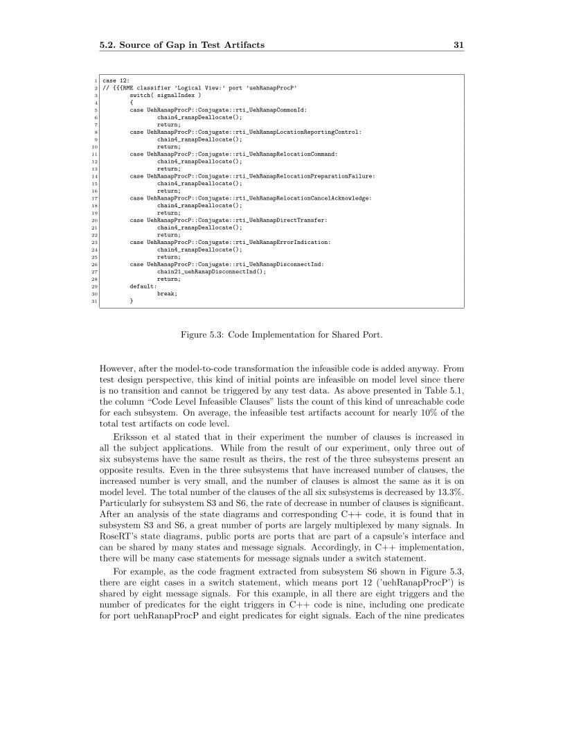
Eriksson et al stated that in their experiment the number of clauses is increased inall the subject applications. While from the result of our experiment, only three out ofsix subsystems have the same result as theirs, the rest of the three subsystems present anopposite results. Even in the three subsystems that have increased number of clauses, theincreased number is very small, and the number of clauses is almost the same as it is onmodel level. The total number of the clauses of the all six subsystems is decreased by 13.3%.Particularly for subsystem S3 and S6, the rate of decrease in number of clauses is significant.After an analysis of the state diagrams and corresponding C++ code, it is found that insubsystem S3 and S6, a great number of ports are largely multiplexed by many signals. InRoseRT’s state diagrams, public ports are ports that are part of a capsule’s interface andcan be shared by many states and message signals. Accordingly, in C++ implementation,there will be many case statements for message signals under a switch statement.
For example, as the code fragment extracted from subsystem S6 shown in Figure 5.3,there are eight cases in a switch statement, which means port 12 (’uehRanapProcP’) isshared by eight message signals. For this example, in all there are eight triggers and thenumber of predicates for the eight triggers in C++ code is nine, including one predicatefor port uehRanapProcP and eight predicates for eight signals. Each of the nine predicates

32 Chapter 5. Experimental Results and Analysis
consists of only one single clause, which makes the number of clauses also nine. However,in the corresponding RoseRT state diagram, the number of predicates for the eight triggersis eight, since the combination of port and signal make up a trigger. Each of the eightpredicates consists of two clauses, which are the combination of port uehRanapProcP andone of the signals. The same port will be combined with eight signals on model level foreight times, which makes the number of clauses sixteen. To make a comparison, there areeight predicates and sixteen clauses before transformation, nine predicates and nine clausesafter transformation. Therefore, it is obvious that the more a port is shared by signals,the more the number of clauses will be decreased on code level, and the less the number ofpredicates will be increased on code level. This is why subsystem S3 and S6 increase theleast in number of predicates and decrease the most in the number of clauses.
5.3 Test Coverage Comparison Between Model and CodeLevel
It is already known that the number of test requirements is increased due to the newintroduced predicates on code level. However, the real test coverage gap between modeland code level remains unknown due to that with a given test suite, though the totaltest requirements are increased, the actually covered test requirements are also increased.Hence, it is necessary to investigate the real test coverage gap by a given test suite. Whereasthe limitation of test environment and lack of tools that can evaluate the real test coverage,especially for RoseRT model, become the obstacles for us to compare the model test coveragewith code test coverage. However, it is possible to create a virtual test suite with specifiedtest data and to investigate how the virtual test suite covers the test artifacts on model andcode level respectively. Then a rough test coverage level can be obtained by calculationsbased on the definition of test coverage on both model and code level. Ammann et al. [3]have provided the definition of test coverage level as blow.
Definition 5.3.1. Coverage Level : Given a set of test requirements TR and a test set T,the coverage level is simply the ratio of the number of test requirements satisfied by T tothe size of TR. [3]
Here in our study, coverage level is referred to as test coverage. According to the defini-tion, the test coverage can be expressed as below equation.
CoverageLevel =Tested (T, S)
Total Existing (S)(5.2)
Test coverage for this virtual test suite will be calculated based on the equation. Takesubsystem S1 for example, assume there is a test suite to be executed, in which there are439 different transition paths are covered by the included test cases. In order to test the439 transition paths, 439 triggers must be satisfied, meaning there are 439 predicates onmodel level evaluated to true. Then have the 439 signals all send on wrong ports, whichwill evaluate the 439 predicates to false. Thus, the test suite would have 878 (439*2) testrequirements tested from the perspective of predicate coverage. Meanwhile, the total numberof test requirements for S1 is 1756(878*2), also shown in Table 5.3. By applying the testedand total test requirements to the equation of test coverage, the predicate coverage on modellevel would be obtained, namely 50% (878/1756). Have the same test suite execute on thecode level, the predicate coverage can be obtained similarly. However, since the actuallycovered predicates in C++ code cannot be exactly accurate, there will be a best and a worst

5.3. Test Coverage Comparison Between Model and Code Level 33
Table 5.4: Predicate Coverage Comparison in S1
case for predicate coverage on code level. Based on the transformation rules, the maximumand minimum number of the predicates that are covered by the same 439 transition paths oncode level can be calculated. As mentioned before, a signal and a port make up the triggerfor a transition, and a port can be shared by multiple signals. The transformation ruledecides the fact that the more a port is shared by signals, the less predicates will be in C++code. Thus, the worst case is that all the 439 signals share the same port, which makes theminimum number of predicates covered on code level 440 (439+1). On the other hand, thebest case is that each of the 439 signals has an exclusive port, meaning there will be 439 ports.Thus, the maximum number of the predicates covered on code level is 878 (439+439). Havingthe covered predicates evaluated to true and false respectively, the minimum and maximumnumber of tested test requirements will be doubled, namely 880(440*2) and 1756(878*2).Meanwhile, on code level, the total number of test requirements for predicate coverage is3070(1535*2), also shown in Table 5.3. Thus, the predicate converge on code level is rangedfrom 28.66% (880/3070) to 57.20% (1756/3070).
In the same way, predicate coverage for test suites with different number of transitionpaths can be calculated on both model and code level. Table 5.4 shows a predicate coveragecomparison between model and code level in subsystem S1, with different number of coveredtransition paths as input. As shown in above example, if the number of tested transitionpaths are provided, the test cases can be designed by evaluating the predicates to true andfalse respectively. The equation can be further expressed as below.
CoverageLevel =Tested TR
Total Existing TR=
TesedPredicate × 2
Total Predicate × 2(5.3)
Thus, in our study the test coverage actually equals to the ratio of tested predicates to thetotal number of predicates. For simplicity, the number of test requirements will be replacedaccordingly.
Note that column Minimum Shared Port means the minimum number of ports thatshared by all signals under a given number of tested transition paths. It is not accurate toalways assume that all ports share one same port since there are constrains on the minimumnumber of ports. For example, when the number of tested paths is greater than 238 it isimpractical to have only one port. If there were only one port shared by 239 signals,the number of the rest of the predicates on model level would be 638 (878-239-1). Thus,according to the transformation rule, for the rest of the 638 predicates, at most they will betransformed to 1292((638-16)*2+16*3) predicates. However, the number of the rest of the
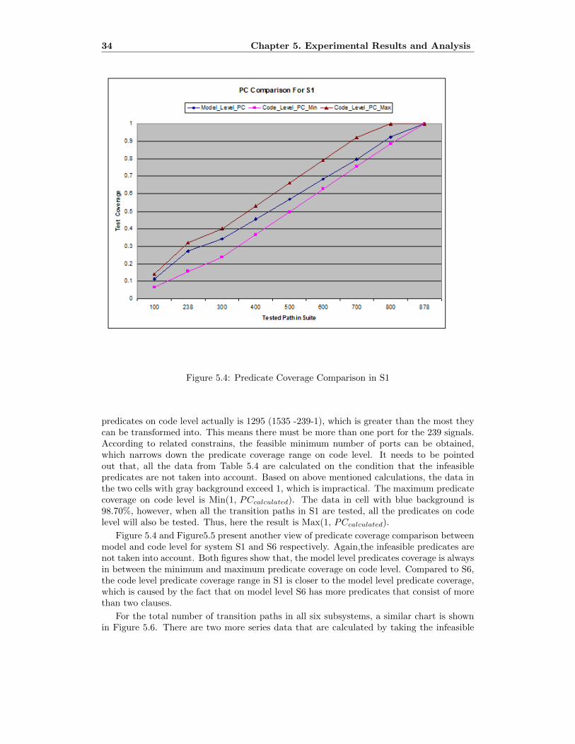
34 Chapter 5. Experimental Results and Analysis
Figure 5.4: Predicate Coverage Comparison in S1
predicates on code level actually is 1295 (1535 -239-1), which is greater than the most theycan be transformed into. This means there must be more than one port for the 239 signals.According to related constrains, the feasible minimum number of ports can be obtained,which narrows down the predicate coverage range on code level. It needs to be pointedout that, all the data from Table 5.4 are calculated on the condition that the infeasiblepredicates are not taken into account. Based on above mentioned calculations, the data inthe two cells with gray background exceed 1, which is impractical. The maximum predicatecoverage on code level is Min(1, PCcalculated). The data in cell with blue background is98.70%, however, when all the transition paths in S1 are tested, all the predicates on codelevel will also be tested. Thus, here the result is Max(1, PCcalculated).
Figure 5.4 and Figure5.5 present another view of predicate coverage comparison betweenmodel and code level for system S1 and S6 respectively. Again,the infeasible predicates arenot taken into account. Both figures show that, the model level predicates coverage is alwaysin between the minimum and maximum predicate coverage on code level. Compared to S6,the code level predicate coverage range in S1 is closer to the model level predicate coverage,which is caused by the fact that on model level S6 has more predicates that consist of morethan two clauses.
For the total number of transition paths in all six subsystems, a similar chart is shownin Figure 5.6. There are two more series data that are calculated by taking the infeasible

5.3. Test Coverage Comparison Between Model and Code Level 35
Figure 5.5: Predicate Coverage Comparison in S6

36 Chapter 5. Experimental Results and Analysis
Figure 5.6: Predicate Coverage Comparison in All Subsystems

5.3. Test Coverage Comparison Between Model and Code Level 37
predicates into account. It is evident that with the infeasible predicates included, the rangeof predicate coverage on code level is biased downward. This is caused by the fact that thetotal number of predicates on code level is increased and the number of tested predicatesremains the same. Furthermore, the maximum predicate coverage is 90.54% (54319/59994),not 100%, since the infeasible predicates will never be covered. Similar to Figure 5.4 and5.5, the model level predicate coverage is still in between the range of code level predicatecoverage.

38 Chapter 5. Experimental Results and Analysis

Chapter 6
Conclusion And Future Work
Based on the MDD environment provided by our industrial partner, this study presents theimpact of the model-to-code transformation on the number of test artifacts. The number ofpredicates P and clauses C were counted before and after the RoseRT model transformationto C++ code. P and C were then used as the basis to calculate the test requirements forthe three logic-based coverage criteria, PC, CC and CACC. Finally a comparison betweenmodel coverage and code coverage were presented based on the virtual test suite that specifythe number of covered transition paths.
Same as the experiment performed by Eriksson et al [5], our experiment found an increasein the number of predicates which causes the increase in the number of test requirementsfor PC, CC and CACC. However, the source that causes the increase are different in ourexperiment. Kirner [9] summarized four possible factors that may contribute to the deviationof structural code coverage at the model and code level:
– (i) The modeling language may use a different implementation style (e.g., data flowinstead of control flow).
– (ii) The modeling language may use components of high abstraction (hiding detailsof complex implementation), which complicate the identification of a structural code-coverage metric’s scopes within the model.
– (iii) Code generation may be parameterizable (i.e., model semantics and implementa-tion depends on the code generation settings).
– (iv) Many modeling environments are under continuous development. Thus, the se-mantics of language constructs may change over time. Further, modeling languagesare rarely standardized, often each tool provider has its own modeling language.
In the experiment of Eriksson et al [5], they studied the effect of abstraction (ii) andparameterized code generation (iii ). Their analysis indicates that the increase in their caseis mainly caused by the fact that the used models contain conditions that are not expressedexplicitly as predicates. In a follow-up empirical study, Eriksson et al [6]presented thatthe test artifacts gap can be greatly narrowed down by introducing some model-to-modeltransformation rules which aims to make the implicit predicates explicit for xtUML modelbefore the model-to-code transformation. After the model-to-model transformation thenumber of test artifacts will be very close to the number after model-to-code transformation.
39

40 Chapter 6. Conclusion And Future Work
However, the effect of implicit predicates was not present in our RoseRT models. Inour experiment, the increase of number of test artifacts is mainly caused by the transfor-mation rules that translate RoseRT models into C++ code. The source that caused theincrease in our case is related to the category code generation (iii ) raised by Kirner [9].Whereas parameterizable code generation is not accurate enough to represent the source ofincrease in our case, thus we suggest transformation rules be added to complement Kirner’sclassification.
Based on the condition that model structural coverage is close to code structural cov-erage, Baresel et al [9] suggested an adaptation of traditional test strategy to model-basedtesting as below:
– 1. Specification-based tests are carried out at model level in order to check whetherthe requirements have been modeled correctly.
– 2. The model coverage reached by the specification-based tests is measured.
– 3. Additional white-box-tests are manually defined or automatically generated in orderto cover the yet uncovered model elements. These tests are executed and evaluated.
– 4. The program code generated from the model is tested with the tests defined in step1 in order to check whether the requirements have been implemented correctly.
If requirements on high code coverage exist, the model-based effective test strategyproceeds as follows:
– 5. The code coverage reached by the specification-based tests is measured.
– 6. Additional white-box-tests are manually defined or automatically generated inorder to cover the as yet uncovered program elements. These tests are executed andevaluated.
Similar to the results presented by Baresel [9], strong correlation between model predicatecoverage and code predicate coverage is also present in our study. Thus the recommendedtest strategy can also be applied to the development environment used in our experiment.
Before the experiments, we assumed the test coverage on model diverged from code level,and we came up with the idea of adding some mechanisms on model level to ensure adequatetesting. However, the results of the experiments are so much better than we expected thatwe believe that there is no need to investigate the mechanisms to be added on model level.Another positive result is that after model-to-code transformation all predicates on codelevel are single-clause predicate, which makes the logic-based testing very easy and cheap.This also is the reason why we only present PC results, since CC and CACC are basicallythe same as PC when there is only one clause in the predicates.
We believe there are several options for future study. Since our experiments are limitedto the MDD tool RoseRT, and RoseRT translates the code from the models in a relativelyfixed and intuitive way, we are not sure if our results will be applied to other model transformtechniques. Hence one future step is to extend the study to other MDD environments andtransform techniques. For RoseRT development software, to make the testing on modellevel more efficient and effective, a future study could be developing a tool based on ourRPP (RoseRT Predicate Parser) for twofold use: design and generation of model test datato achieve 100% model test coverage, and evaluation of model test coverage for a existingmodel test suite.

Bibliography
[1] Ragnhild Van Der Straeten, Tom Mens, and Stefan Van Baelen, ”Challenges in Model-Driven Software Engineering”
[2] P. Baker and C. Jervis, ”Early UML model testing using TTCN-3 and the UML test-ing profile”, In Testing: Academic and Industrial Conference Practice and ResearchTechniques, TAIC PART-Mutation 2007, pp. 47-54, 2007.
[3] Paul Ammann and Jeff Offutt. Introduction to Software Testing, 2008
[4] Object Management Group, MDA Guide, Version 1.0.1, OMG Document omg/2003-06-01 (2003).
[5] Anders Eriksson, Birgitta Lindstrom, Sten F. Andler, Jeff Offutt. Model TransformationImpact on Test Artifacts: An Empirical Study
[6] Anders Eriksson, Birgitta Lindstrom, Sten F. Andler, Jeff Offutt .Transformation Rulesfor Platform Independent Testing: An Empirical Study
[7] S. J. Mellor and M. J. Balcer. Executable UML: A Foundation for Model Driven Archi-tecture. Boston: Addison Wesley, ISBN 0-201-74804-5,
[8] A. Kleppe, J. Warmer, and W. Bast, MDA Explained, The Model Driven Architecture:Practice and Promise, Addison- Wesley, Boston, MA (2003).
[9] Raimund Kirner. ”Towards PreservingModel Coverage and Structural Code Coverage”.EURASIP Journal on Embedded SystemsVolume 2009, Article ID 127945
[10] D. S. Frankel, Model Driven Architecture: Applying MDA to Enterprise Computing,Wiley Press, Hoboken, NJ (2003).
[11] Object Management Group, The Unified Modeling Language 1.5, OMG Document:formal/03-03-01
[12] Krzysztof Czarnecki and Simon Helsen. ”Classification of Model Transformation Ap-proaches”. OOPSLA’03 Workshop on Generative Techniques in the Context of Model-Driven Architecture.
[13] Krzysztof Czarnecki and Simon Helsen.”Feature-based survey of model transformationapproaches”
[14] Dalal, S.R., et al. Model-based testing in practice. in International Conference on Soft-ware Engineering. 1999: IEEE.
41

42 BIBLIOGRAPHY
[15] Mohamed Mussa, Samir Ouchani, Waseem Al Sammane, Abdelwahab Hamou-Lhadj.”A Survey of Model-Driven Testing Techniques” ,2009 Ninth International Conferenceon Quality Software.
[16] Bertolino, A. Software testing research: Achievements, challenges, dreams. in Workshopon the Future of Software Engineering.2007: IEEE.
[17] H. Gomaa. Designing concurrent, distributed, and real-time applications with uml. InICSE ’01: Proceedings of the 23rd International Conference on Software Engineering,pages 737-738, Washington, DC, USA, 2001.IEEE Computer Society.
[18] Rational Modeling Language Guide. Rational Rose RealTime Help, VERSION:2003.06.00.
[19] RTCA. RTCA Inc. DO-178B: Software Considerations In Airborne Systems and Equip-ment Certification. Requirements and Technical Concepts for Aviation.1992.
[20] J. J. Chilenski and S. P. Miller. Applicability of modified condition/decision coverageto software testing. Software Engineering Journal, 9(5):193-200,sep 1994.
[21] P. Ammann, J. Offutt, and H. Huang. Coverage criteria for logical expression. In Pro-ceedings of the 14th International Symposium on Software Reliability Engineering, pages99-107. IEEE Computer Society Press, November 2003.
[22] G. Myers. The Art of Software Testing. John Wiley and Sons, New York NY, 1979.
[23] John Chilenski and L. A. Richey. Definition for a masking form of modifiedconditiondecision coverage (MCDC). Technical report, Boeing, Seattle WA, 1997.http://www.boeing.com/nosearch/mcdc/.
[24] J. J. Chilenski. An investigation of three forms of the modified condition decision cov-erage (MCDC) criterion. Technical report, Office of Aviation Research, 2001.
[25] Andre Baresel, Mirko Conrad, Sadegh Sadeghipour and Joachim Wegener. The Inter-play between Model Coverage and Code Coverage. European Community under the 5thFramework Programme (GROWTH).
[26] TargetLink Production Code Generation Guide, dSpace Inc., www.dspaceinc.com ,2001.
[27] Using Simulink (Version 4.1). The MathWorks Inc., Natick (US), 2000.
[28] Stateflow User’s Guide (Version 4). The MathWorks Inc., Natick (US), 2000.
[29] Model Coverage Tool, The MathWorks Inc., www.mathworks.com/products/slperftools/,2001.
[30] Pitschinetz, R.: Das Testsystem TESSY Version 2.5 (in German). Technical ReportFT3/S-1999-001. DaimlerChrysler AG,Berlin, 1999.
[31] A. Rajan, M. W. Whalen, and M. P. Heimdahl. The Effect of Program and ModelStructure on MC/DC Test Adequacy Coverage. In ICSE ’08, pages 161-170, New York,NY, USA, 2008. ACM.