model rs60ac air compressor operators, maintenance … · operators, maintenance and parts manual...
TRANSCRIPT

MODEL RS60ACAIR COMPRESSOR
OPERATORS, MAINTENANCEAND PARTS MANUAL
P/N: 30417305/21/2007 DCL


2
OPERATORS, MAINTENANCE, AND PARTS MANUALAUTO CRANE MODEL RS60AC
TABLE OF CONTENTS
Operation & Maintenance Section
Specifications ...................................................................................................................... 3
Safety ............................................................................................................................ 4 - 8
Compressor Terminology .................................................................................................... 9
Description of Components ....................................................................................... 10 - 13
Inspection, Lubrication, and Maintenance ................................................................. 14 - 21
Troubleshooting ......................................................................................................... 22 - 24
Compressor Operation .............................................................................................. 25 - 26
Parts and Illustration Section .................................................................................... 27 - 35
Recommended Spare Parts ............................................................................................... 36
Service Questionnaire ........................................................................................................ 37
Instructional Procedures For Installation ................................................................... 38 - 41


3
SPECIFICATIONS
GISP051@YREVILED MFC 54 06
rosserpmoCotdeepStupnI MPRMPG
0051@01
ISP0742
1591@31
ISP0742
rosserpmoC-yticapaCdiulF)ciluardyhton(
metsySsnollaG0.1pmuSrosserpmoC57.
metsySrosserpmoC-stnenopmoC )snoisnemiDllarevO(wolebees
)yrd(thgieW .sbl003
SPECIFICATIONS SUBJECT TO CHANGE WITHOUT PRIOR NOTICE
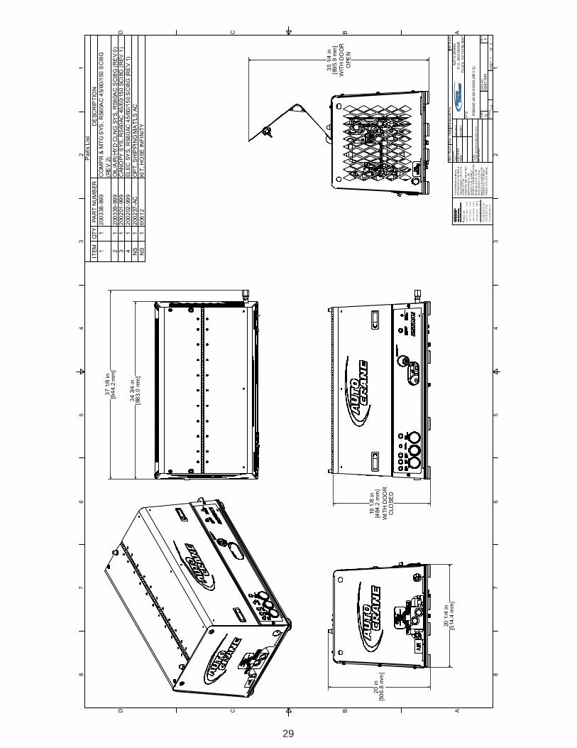
34 3/4 in[883.0 mm]
37 1/8 in[944.2 mm]
19 1/8 in[484.2 mm]
WITH DOORCLOSED
20 1/4 in[514.4 mm]
20 in[506.8 mm]

4
WARNING
AIR COMPRESSOR SAFETY PRECAUTIONS
Safety is basically common sense. While there are standard safety rules, each situation has its ownpeculiarities that cannot always be covered by rules. Therefore with your experience and commonsense, you are in a position to ensure your safety. Lack of attention to safety can result in:accidents, personal injury, reduction of efficiency and worst of all - Loss of Life. Watch for safetyhazards. Correct them promptly. Use the following safety precautions as a general guide to safeoperation:
Do not attempt to remove any compressor parts without first relieving the entire system ofpressure.
Do not attempt to service any part while machine is operating.
DANGER
Do not operate the compressor at pressure(s) or speed in excess of its rating as indicated in“Compressor Specifications”.
Periodically check all safety devices for proper operation.
Do not play with compressed air. Pressurized air can cause serious injury to personnel.
Exercise cleanliness during maintenance and when making repairs by covering parts and exposedopenings.
SAFETY
ALL UNITS ARE SHIPPED WITH A DETAILED OPERATORS AND PARTSMANUAL. THIS MANUAL CONTAINS VITAL INFORMATION FOR THE SAFEUSE AND EFFICIENT OPERATION OF THIS UNIT. CAREFULLY READTHE OPERATORS MANUAL BEFORE STARTING THE UNIT. FAILURE TOADHERE TO THE INSTRUCTIONS COULD RESULT IN SERIOUS BODILYINJURY OR PROPERTY DAMAGE.
CHECK THE COMPRESSOR SUMP OIL LEVEL ONLY WHEN THE COMPRESSORIS NOT OPERATING AND SYSTEM IS COMPLETELY RELIEVED OF PRESSURE.OPEN SERVICE VALVE TO ENSURE RELIEF OF SYSTEM AIR PRESSURE WHENPERFORMING MAINTENANCE ON COMPRESSOR AIR/OIL SYSTEM. FAILURETO COMPLY WITH THIS WARNING MAY CAUSE DAMAGE TO PROPERTYAND SERIOUS BODILY HARM.

5
SAFETY
Do not install a shut-off valve between the compressor and compressor oil sump.
DANGER
Do not disconnect or bypass safety circuit system.
Do not install safety devices other than authorized AUTO CRANE replacement devices.
Close all openings and replace all covers and guards before operating compressor unit.
Tools, rags, or loose parts must not be left on the compressor or drive parts.
Do not use flammable solvents for cleaning parts. This can cause the unit to ignite during operation.
Keep combustibles out of and away from the Compressor/Inlet and any associated enclosures.
The owner, lessor, or operator of the Compressor are hereby notified and forewarned that anyfailure to observe these safety precautions may result in damage or injury.
AUTO CRANE expressly disclaims responsibility or liability for any injury or damage caused byfailure to observe these specified precautions or by failure to exercise that ordinary caution anddue care required when operating or handling the Compressor, even though not expressly specifiedabove.
DO NOT USE AUTO CRANE COMPRESSOR SYSTEMS TO PROVIDE BREATHINGAIR. SUCH USAGE, WHETHER SUPPLIED IMMEDIATELY FROM THECOMPRESSOR SOURCE, OR SUPPLIED TO BREATHING TANKS FORSUBSEQUENT USE, CAN CAUSE SERIOUS BODILY INJURY.
AUTO CRANE DISCLAIMS ANY AND ALL LIABILITIES FOR DAMAGE FOR LOSSDUE TO PERSONAL INJURIES, INCLUDING DEATH, AND/OR PROPERTYDAMAGE INCLUDING CONSEQUENTIAL DAMAGES ARISING OUT OF ANYAUTO CRANE COMPRESSORS USED TO SUPPLY BREATHING AIR.

6
SAFETY
A compliment of warning decals is supplied with each unit. These decals must be affixed to thecomressor package in the locations noted in this manual. If for any reason a safety decal isremoved it is the owners responsibility to make sure it is replaced.

7

8
304174

9
COMPRESSOR TERMINOLOGY
AIR/OIL COALESCER - Performs second stage separation of oil from compressed air feedingair tools. Sometimes referred to as the separator element.
CFM - Refers to the volume of compressed air being produced, expressed as cubic feet of air perminute.
COMPRESSOR LUBRICANT - DEXTRON III ATF.
GPM - Refers to the amount of gallons per minute of hydraulic fluid flowing through the pump.
OIL SUMP - The first stage of oil separation from compressed air. Also serves as reservoir areafor compressor lubricant and sometimes referred to as the receiver tank.
PSI - Refers to the operating pressure the system is set up at, expressed as pounds per squareinch.
SAFETY VALVE - A valve located on the oil sump which opens in case of excessive pressure.Sometimes referred to as the pop-off or pressure relief valve.

10
DESCRIPTION OF COMPONENTS
COMPRESSOR ASSEMBLY
The AUTO CRANE hydraulic drive compressor assembly is a positive displacement, oil flooded,rotary screw type unit employing one stage of compression to achieve the desired pressure.Components include a housing (stator), two screws (rotors), bearings, and bearing supports.Power from the hydraulic motor shaft is transferred to the male rotor through a drive coupling.The female rotor is driven by the male rotor. There are five lobes on the male rotor while thefemale rotor has six roots.
PRINCIPLES OF OPERATION
In operation, two helical grooved rotors mesh to compress air. Inlet air is trapped as the malelobes roll down the female grooves, pushing trapped air along, compressing it until it reaches thedischarge port in the end of the stator and delivers smooth-flowing, pulse-free air to the receiver.
During the compression cycle, oil is injected into the compressor and serves these purposes:
1. Lubricates the rotating parts and bearings.2. Serves as a cooling agent for the compressed air.3. Seals the running clearances.
LUBRICATION SYSTEM
Oil from the compressor at discharge pressure, is directed into it’s integral housing, through thethermal valve and filter, and then out of the integral housing to the oil cooling system, and then backto the side of the compressor stator, where it is injected into the compressor. At the same time oilis directed internally to the bearings and shaft seal of the compressor.
OIL SUMP
Compressed, oil-laden air enters the sump from the compressor. As the oil-laden air enters thesump, most of the oil is separated from the air as it passes through a series of baffles and de-fusionplates. The oil accumulates at the bottom of the sump for recirculation. However, some smalldroplets of oil remain suspended in the air and are passed on to the Coalescer.

11
DESCRIPTION OF COMPONENTS
SAFETY VALVE
The pop safety valve is set at 200 PSI and is located at the top of the air/oil sump. This valve actsas a backup to protect the system from excessive pressure that might result from a malfunction.
AIR/OIL COALESCER
The coalescer is self-contained within a spin-on housing. When air is demanded at the service line,it passes through the coalescer which efficiently provides the final stage of oil separation.
OIL RETURN LINE
The oil that is removed by the coalescer accumulates and is returned through an internal oil returnline leading to the compressor.
MINIMUM PRESSURE VALVE
The minimum pressure valve is located at the outlet of the coalescer head and serves to maintain aminimum discharge pressure of 75 PSIG in operation, which is required to assure adequatecompressor lubrication pressure.
OIL FILTER
The compressor oil filter is a removable and cleanable screen built into the side of the compressorhousing. Screen replacement may be necessary after several cleanings.
COMPRESSOR OIL AND HYDRAULIC OIL COOLING SYSTEMS
The compressor cooling system consists of a combination hydraulic cooler and compressor coolermounted on the common frame. Compressor oil temperature is controlled by a thermal valvelocated down stream of the oil filter. The thermal valve maintains the compressor oil temperatureat 185ºF. Cool air is drawn through the vented end panel and across the combo cooler. The air isheated by the coolers and the hot air exits out the back vented panel . Allow for adequateclearance (12”) for the air to exit. Also, the package location should not be subjected to aboveambient air temperatures.

12
DESCRIPTION OF COMPONENTS
INSTRUMENTATION
The AUTO CRANE hydraulic drive compressor unit incorporates a gauge panel that monitorstemperature, pressure and hours of operation.
HOURMETER
The hourmeter records the total number of operating hours. It serves as a guide in following therecommended inspection and maintenance schedule. The hourmeter will only run when there is pressurein the system.
COMPRESSOR DISCHARGE AIR/OIL TEMPERATURE SWICHGAUGE
This swichgauge indicates compressor air discharge temperature. The swichgauge ensures safetyshutdown in case of excessive operating temperatures, preventing compressor damage, by stoppinghydraulic flow to the compressor motor.
ELECTRICAL AND SAFETY SYSTEM
The AUTO CRANE compressor’s standard electrical system consists of:-Gauge panel with a temperature swichgauge, hourmeter and discharge pressure swichgauge.-Compressor and hydraulic oil cooler fan assembly and relay.-Compressor after cooler/oil cooler fan assembly with relay.-N.O. hourmeter pressure switch.-N.C. blowdown pressure switch.-12VDC N.O. hydraulic solenoid and relay.-Switch relay for customer equipment interface during compressor operation.

13
DESCRIPTION OF COMPONENTS
AUTOMATIC BLOW DOWN VALVE
There is one blow down valve in the compressor system. It is located at the intake valve and willautomatically bleed the sump to zero pressure when the compressor is disengaged. Blow downtime interval takes between 45 and 60 seconds.
CONTROL SYSTEM
The prime component of the compressor control system is the compressor inlet valve. The controlsystem is designed to match air supply to air demand and to prevent excessive discharge pressurewhen compressor is at idle. Control of air delivery is accomplished by the inlet valve regulationand modulation as directed by the discharge pressure regulator.
NORMALY OPEN REGULATOR SOLENOID
A closed Furnas air pressure switch will energize the normaly open regulator solenoid, thus closingit. When the normaly open regulator solenoid is closed, air pressure will rise. When it is open airpressure falls only in the compressor sump.
Note: See page 28 for description of Furnas switch.
NOTE: Most air tools operating pressure range is between 90 and 125 psi. Operatingabove the tools recommended pressures will decrease the life of the tool. Higheroperating pressure can also over torque nut and bolts fatiguing the fastener and matingparts. Strictly adhere to tool operating pressures and torque standards set forth by thetool manufacturer and the specifications of the equipment that work is being performedon.
INLET VALVE
The compressor inlet valve is a piston operated disc valve that regulates the inlet opening to controlcapacity and serving as a check valve at shutdown.

14
INSPECTION, LUBRICATION, AND MAINTENANCE
This section contains instructions for performing the inspection, lubrication, and maintenanceprocedures required to maintain the compressor in proper operating condition. The importance ofperforming the maintenance described herein cannot be over emphasized.
The periodic maintenance procedures to be performed on the equipment covered by this manualare listed below. It should be understood that the intervals between inspections specified aremaximum interval. More frequent inspections should be made if the unit is operating in a dustyenvironment, in high ambient temperature, or in other unusual conditions. A planned program ofperiodic inspection and maintenance will help avoided premature failure and costly repairs. Dailyvisual inspections should become a routine.
The LUBRICATION AND MAINTENANCE CHART lists serviceable items on this compressorpackage. The items are listed according to their frequency of maintenance, followed by thoseitems which need only “As Required” maintenance.
The maintenance time intervals are expressed in hours. The hourmeter shows thetotal number of hours your compressor has run. Use the hourmeter readings for determining yourmaintenance schedules. Perform the maintenance at multiple intervals of the hours shown. Forexample, when the hourmeter shows “100” on the dial, all items listed under “EVERY 10 HOURS”should be serviced for the tenth time, and all items under “EVERY 50 HOURS” should beserviced for the second time, and so on.
DANGER
COMPRESSOR MUST BE SHUT DOWN AND COMPLETELY RELIEVED OFPRESSURE PRIOR TO CHECKING FLUID LEVELS. OPEN SERVICE VALVE TOENSURE RELIEF OF SYSTEM AIR PRESSURE. FAILURE TO COMPLY WITH THISWARNING MAY CAUSE DAMAGE TO PROPERTY AND SERIOUS BODILY HARM.

15
LUBRICATION AND MAINTENANCE CHART
NOTE: Compressor oil and filter is to be changed after the first 50 hours of operation. After this,normal intervals are to be followed.
LAVRETNI NOITCA
YLLACIDOIREPGNIRUD
NOITAREPO
egnahcynaetoN.gnidaereguagllaevresbO.1ehtenimreteddnagnidaerlamronehtmorf
:ETON(.edamsriaperyrassecenevaH.esuacnehwgnidaereguaglausuehtsi"LAMRON"
yadotyadanosnoitidnocralimistagnitarepo).noitarepo
YLIAD
.levelliorosserpmocehtkcehC.1rotacidniporderusserP.retlifriakcehC.2
.gnitareposirosserpmocelihw.skaelriadnaliorofkcehC.3
.sehctiwstiucricytefaskcehC.4
SRUOH52YREVEYLHTNOMRO .liorosserpmocmorfretawniarD.1
005YREVE6ROSRUOH
SHTNOM
neercsecalperdnaliorosserpmocegnahC.1.egakaelroflaestfahsrosserpmockcehC.2
.spmalcdnasgnittif,gnipipretlifriakcehC.3.stroppusrosserpmockcehC.4
retrohS(.tnemeleretlifriawenllatsnI.5ytsudrednuyrassecenebyamlavretni
).snoitidnoc.evlavytefaspmuskcehC.6
0001YREVE1ROSRUOH
RAEY.tnemelegnicselaocegnahC.1
ROYLLACIDOIREPDERIUQERSA
.tnemeleretlifrianaelcdnatcepsnI.1recselaocno-nipsecalperdnatcepsnI.2
.yrassecenfitnemele.snifrelooclionaelcdnatcepsnI.3

16
LUBRICANT RECOMMENDATIONS
WARNING
The following are general characteristics for a rotary screw lubricant. Due to the impossibility ofestablishing limits on all physical and chemical properties of lubricants which can affect theirperformance in the compressor over a broad range of environmental influences, the responsibilityfor recommending and consistently furnishing a suitable heavy duty lubricant must rest with theindividual supplier if they choose not to use the recommended AUTO CRANE rotary screwlubricant. The lubricant supplier’s recommendation must, therefore, be based upon not only thefollowing general characteristics, but also upon his own knowledge of the suitability of therecommended lubricant in helical screw type air compressors operating in the particularenvironment involved.
CAUTION
IT IS IMPORTANT THAT THE COMPRESSOR OIL BE OF A RECOMMENDEDTYPE AND THAT THIS OIL AS WELL AS THE AIR FILTER, OIL FILTER, ANDCOALESCER ELEMENTS BE INSPECTED AND REPLACED AS STATED IN THISMANUAL.
THE COMBINATION OF A COALESCER ELEMENT LOADED WITH DIRT ANDOXIDIZED OIL PRODUCTS TOGETHER WITH INCREASED AIR VELOCITY AS ARESULT OF THIS CLOGGED CONDITION MAY PRODUCE A CRITICAL POINTWHILE THE MACHINE IS IN OPERATION WHERE IGNITION CAN TAKE PLACEAND COULD CAUSE A FIRE IN THE OIL SUMP.
FAILURE TO COMPLY WITH THIS WARNING MAY CAUSE DAMAGE TOPROPERTY AND SERIOUS BODILY HARM.
MIXING DIFFERENT TYPES OR BRANDS OF LUBRICANTS IS NOTRECOMMENDED DUE TO THE POSSIBILITY OF A DILUTION OF THEADDITIVES OR A REACTION BETWEEN ADDITIVES OF DIFFERENT TYPES.

17
LUBRICANT RECOMMENDATIONS
LUBRICANT CHARACTERISTICS
1. Flash point 400°F minimum.2. Pour point -40°F.3. Contains rust and corrosion inhibitors.4. Contains foam suppressors.5. Contains oxidation stabilizer.
NOTE
NOTE
DUE TO ENVIRONMENTAL FACTORS THE USEFUL LIFE OF ALL “EXTENDEDLIFE” LUBRICANTS MAY BE SHORTER THAN QUOTED BY THE LUBRICANTSUPPLIER. AUTO CRANE ENCOURAGES THE USER TO CLOSELY MONITORTHE LUBRICANT CONDITION AND TO PARTICIPATE IN AN OIL ANALYSISPROGRAM WITH THE SUPPLIER.
NO LUBRICANT, HOWEVER GOOD AND/OR EXPENSIVE, CAN REPLACEPROPER MAINTENANCE AND ATTENTION. SELECT AND USE IT WISELY.

18
MAINTENANCE
If some of the maintenance intervals in the schedule outlined in this manual seem to be rather short,it should be considered that one hour’s operation of a compressor is equal to about 40 road mileson an engine. Thus, eight hours operation is equal to 320 road miles, 250 hours is equal to 10,000road miles, etc.
COMPRESSOR OIL SUMP FILL, LEVEL, AND DRAIN
Before adding or changing compressor oil make sure that the compressor is completely relieved ofpressure. Oil is added at the fill cap on the side of the compressor body. A drain valve/hoseassembly is provided at the bottom of the compressor body. The proper oil level, when unit is shutdown and has had time to settle between the top and the midpoint of the upper oil sightglass. Thetruck must be level when checking the oil. DO NOT OVERFILL. The oil sump capacity is givenin “Compressor Specifications”.
DANGER
AIR INTAKE FILTER
The air intake filter is a heavy-duty dry type high efficiency filter designed to protect thecompressor from dust and foreign objects. Optional two-stage available.
Optional filter is equipped with an evacuator cup for continuous dust ejection while operating andwhen stopped.
Frequency of maintenance of the filter depends on dust conditions at the operating site. The filterelement must be serviced when clogged (maximum pressure drop for proper operation is 15”of water). The filter is equipped with a pressure drop indicator, and the element should bechanged based on it’s reading first and then by the maintenance intervals outlined.
DO NOT ATTEMPT TO DRAIN CONDENSATE, REMOVE THE OIL LEVEL FILLPLUG, OR BREAK ANY CONNECTION IN THE AIR OR OIL SYSTEM WITHOUTSHUTTING OFF COMPRESSOR AND MANUALLY RELIEVING PRESSURE FROMTHE SUMP. FAILURE TO COMPLY WITH THIS WARNING MAY CAUSE DAMAGETO PROPERTY AND SERIOUS BODILY HARM.

19
MAINTENANCE
AIR/OIL COALESCER
The air/oil coalescer employs an element permanently housed within a spin-on canister. This is asingle piece unit that requires replacement when it fails to remove the oil from the discharge air, orpressure drop across it exceeds 15 PSI. Dirty oil clogs the element and increases the pressuredrop across it.
To replace element proceed as follows:
1. Shutdown compressor and wait for complete blow down (zero pressure).2. Turn element counterclockwise for removal (viewing element from bottom).3. Apply a film of fluid directly to seal on the new element.4. Rotate element clockwise by hand until element contacts seal (viewing element from
bottom).5. Rotate element approximately one more turn clockwise with band wrench near the top
of element.6. Run system and check for leaks.
WARNING
COALERSCER OIL RETURN
This originates at the bottom of the air/oil coalescer and flows through a special recoverypipe and venturi nozzle. If the coalerscer starts to fill with oil there is a good chance theventuri or pipe has been plugged. Consult factory for cleaning instructions.
DO NOT SUBSTITUTE ELEMENT. USE ONLY A GENUINE AUTO CRANEREPLACEMENT ELEMENT. THIS ELEMENT IS RATED AT 200 PSI WORKINGPRESSURE. USE OF ANY OTHER ELEMENT MAY BE HAZARDOUS AND COULDIMPAIR THE PERFORMANCE AND RELIABILITY OF THE COMPRESSOR,POSSIBLY VOIDING THE WARRANTY AND/OR RESULTING IN DAMAGE TOPROPERTY AND SERIOUS BODILY HARM.
20
MAINTENANCE
OIL FILTER
The compressor oil filter is a throwaway type cartridge. It is designed with a built-in bypass so thatif there is a large restriction, due to cold oil or clogged element, the compressor will still belubricated.
To replace filter proceed as follows:1. Make sure system pressure is relieved.2. Unscrew with 14mm allen wrench.3. Remove oil filter from housing.4. Replace the oil filter screen element.5. Reinsert oil filter screen into housing and tighten with 14mm allen wrench.6. Add oil (total system takes one gallon), re-tighten filler cap.7. Check for leaks in operation.
WARNING
HYDRAULIC OIL COOLER AND COMPRESSOR OIL COOLER COMBINATION
The interior of the oil cooler should be cleaned when the pressure drop across it at full flowexceeds 25 PSI. The following procedure has been recommended by the vendor who supplies thecooler:
1. Remove cooler.2. Circulate a suitable solvent to dissolve and remove varnish and sludge.3. Flush generously with compressor lubricant (compressor oil cooler section only, use
hydraulic oil to flush the hydraulic cooler portion on the combo cooler).4. Once the coolers are reinstalled, fill the compressor and hydraulic systems with the
proper fluids to their appropriate levels.
DO NOT SUBSTITUTE ELEMENT. USE ONLY A GENUINE AUTO CRANEREPLACEMENT ELEMENT. USE OF ANY OTHER ELEMENT MAY BEHAZARDOUS AND COULD IMPAIR THE PERFORMANCE AND RELIABILITYOF THE COMPRESSOR, POSSIBLY VOIDING THE WARRANTY AND/ORRESULTING IN DAMAGE TO PROPERTY AND SERIOUS BODILY HARM.

21
MAINTENANCE
SHAFT SEAL
SHAFT SEAL INSTALLATION INSTRUCTIONS:
1. Remove hydraulic motor, drive coupling and adapter housing from face of compressor.
2. Remove coupling hub from compressor shaft.
3. Remove 4 screws from shaft seal cover and press seal out.
4. Pull seal wear sleeve off shaft with puller.
5. Clean shaft surface removing all burrs from shaft where the wear sleeve gets installed.
6. Press new wear sleeve on to shaft. Oil heating new wear sleeve to 212°F approximatelyaids in the installation of this ring.
7. Press new seal into housing with seal assembly tool, until contact with snapring.
8. Temporarily install new seal installation cone over shaft to protect seal during reinstallation.
9. Reinstall cover.
10. Reverse steps 2 then 1.

22
TROUBLESHOOTING
This section contains instructions for troubleshooting the equipment following a malfunction.
The troubleshooting procedures to be performed on the equipment are listed below. Eachsymptom of trouble for a component or system is followed by a list of probable causes of thetrouble and suggested procedures to be followed to identify the cause.
In general, the procedures listed should be performed in the order in which they are listed, althoughthe order may be varied if the need is indicated by conditions under which the trouble occurred. Inany event, the procedures which can be performed in the least amount of time and with the leastamount of removal or disassembly of parts, should be performed first.
UNPLANNED SHUTDOWNWhen the operation of the machine has been interrupted by an unexplained shutdown, check thefollowing:
1. Check the fuel level and truck dash gauges and indications for possible engineproblems.
2. Check the compressor discharge temperature/switchgauge. If the latching relay circuitis tripped the 12VDC solenoid will loose power and divert hydraulic oil back to thereservoir. The compressor blowdown pressure switch and the temperature switchgaugewill not allow power to the hydraulic solenoid until the air has blown down and thetemperature has dropped into it’s normal operating range and the push button has beenre-set. Take compressor in for service once a high temperature shutdown hasoccurred. Failure to do so will void your warranty.
3. Check that the compressor oil is at proper level.4. Check oil cooler for dirt, slush, ice on the fins, or any other obstructions to the cooling
air flow.5. Make a thorough external check for any cause of shutdown such as broken hose,
broken oil lines, loose or broken wire, etc.

23
TROUBLESHOOTING
IMPROPER DISCHARGE PRESSURE
1. If discharge pressure is too low, check the following:
A. Too much air demand. (Air tools require more air than what the compressor canproduce, air tools are free wheeling without resistance.)
B. Service valve wide open to atmosphere.C. Leaks in service line.D. Restricted compressor inlet air filter.E. Faulty control system operation (i.e.N.0. regulated air solenoid is allowing air through
all the time.)F. Furnas Switch is not closing at 115 psi.G. Low compressor oil level.
2. If discharge pressure is too high, safety valve blows, or system shuts down on high pressure,check the following:
A. Faulty discharge pressure swichgauge.B. Coalescer plugged up.C. Faulty safety valve.D. N.O. regulated air solenoid is not opening.E. Furnas switch is not opening at 150 psi.
3. Sump relief valve activates:
A. Inlet valve leaking or open.
B. Faulty relief valve.
C. Faulty Furnes switch, or N.O. regulated air solenoid, or pressure switchgauge.
SUMP PRESSURE DOES NOT BLOW DOWN
If after the compressor is shutdown, pressure does not automatically blow down, check for:
1. Automatic blow down valve may be inoperative.2. Blockage in air line from side of inlet valve to blow down valve pilot port 1.3. Blow down valve orifice is clogged.
OIL CONSUMPTION
Abnormal oil consumption or oil in service line, check for the following:
1. Over filling of oil sump.2. Leaking oil lines or oil cooler.3. Plugged oil return line: check nozzle beneath the sightglass.4. Defective coalescer element.5. Compressor shaft seal leakage.

24
TROUBLESHOOTING
COALESCER PLUGGING
If the coalescer element has to be replaced frequently because it is plugging up, it is an indicationthat foreign material may be entering the compressor inlet or the compressor oil is breaking down.
Compressor oil can break down prematurely for a number or reasons.(1) Extreme operating temperature, (2) negligence in draining condensate from oil sump, (3) usingthe improper type of oil, (4) dirty oil, (5) oil return nozzle plugged.
The complete air inlet system should be checked for leaks.
HIGH COMPRESSOR DISCHARGE TEMPERATURE
1. Check compressor oil level. Add oil if required (see Section for oil specifications).2. Check thermal valve operation.3. Clean outside of oil cooler.4. Clean oil system (cooler) internally.5. Check fan relay harness.

25
COMPRESSOR OPERATION
Before starting the compressor, read this section thoroughly. Familiarize yourself with the controls andindicators, their purpose, location, and use.
ROLORTNOCROTACIDNI ESOPRUP
ERUTAREPMETEGUAGHCIWS
diulf/riaehtfoerutarepmetehtsrotinoMlamronehT.rosserpmocehtgnivaelerutxim012ot571yletamixorppaebdluohsgnidaer
ehtnehwyalerotlangissdneS.Fseergedseerged042sehcaerrosserpmoc
tuhslliwrosserpmocehtdnaerutarepmet.nwod
ERUSSERPEGUAGHCTWS
.knatpmusehtedisnierusserpehtsrotinoMehtISP561sehcaererusserpehtnehW
nwodtuhslliwrosserpmoc
RETEMRUOH lautcafosruohdetalumuccarotacidnI.noitareporosserpmoc
LEVELDIULFSESSALGTHGIS
reporP.pmusehtnileveldiulfsetacidnIfopotdnatniopdimneewtebebdluohslevel
nehwlevelsihtkcehC.ssalgthgisreppuehtehtdnadegagnesidsirosserpmoceht
.dnuorglevelnodekrapsielcihev
FEILERERUSSERPEVLAV
fierehpsomtaehtoterusserppmusstneV571sdeecxepmusehtedisnierusserpeht
.ISP
TELNIROSSERPMOCEVLAVLORTNOC
niekatniriafotnuomaehtsetalugeRdesserpmocfotnuomaehthtiwecnadrocca
rosserpmocnidiulfsetalosI.desugniebria.nwodtuhsnotinu
HCTIWSSANRUFedivorpotpmusmorferusserpriasesneS
riadetaluger.O.Nehtfolortnoccitamotua.dionelos
RIADETALUGER.O.NDIONELOS
rofevlavekatnioterusserpriasdneS.noitaugercitamotua
EVLAVNWODWOLB erehpsomtaehtoterusserppmusehtstneV.nwodtuhsta
ERUSSERPMUMINIMEVLAV
dnapmusecnalabotwolfriastcitseRfomuminimaserussA.erusserpriaecivres
.noitacirbulrosserpmocniatniamotISP56
26
COMPRESSOR OPERATION
OPERATING CONDITIONS
The following conditions should exist for maximum performance of the compressor. The truckshould be as close to level as possible when operating. The compressor will operate on a 15degree sideward and lengthwise tilt without any adverse problems. Operation in ambient tempera-tures above 100°F (38°C) may experience high temperature shutdown.
NOTE
NOTE
IF THE COMPRESSOR IS BEING USED TO POWER SANDBLASTING EQUIP-MENT, OR AN AIR STORAGE TANK, USE A CHECK VALVE DIRECTLY AFTERTHE MINIMUM PRESSURE VALVE TO PREVENT BACKFLOW INTO THE SUMP.THIS CHECK VALVE SHOULD HAVE A MAXIMUM PRESSURE DROP RATINGOF 2 PSIG (13.78kPa) OPERATING AND A CAPACITY RATING EQUAL TO THECOMPRESSOR.
A COMPRESSOR SERVICE VALVE SHOULD BE LOCATED TO THE HOSE REELINLET OR THE CUSTOMERS AIR CONNECTION PORT WHEN A HOSE REEL ISNOT USED. TYPICAL PLUMBING FROM THE MACHINES AIR OUTLET PORTIN THE FOLLOWING ORDER:
1. MOISTURE TRAP/GAUGE/OILER COMBINATION (WHEN USED).2. AIR TANK (WHEN USED).3. HOSE REEL (WHEN USED).
27
PARTS AND
ILLUSTRATION
SECTION

28
TROP NOITPIRCSED
A TROPTOLIPOTYLNONWODTUHSTA,YLPPUSLANGISRIA.RIAPMUSSTSUAHXE.EVLAVNWODWOLBNO'P'
B
.O.NMORFLANGISERUSSERPRIADETALUGERTELTUOSIERUSSERPRIA.EVLAVDIONELOSROTALUGERMAERTSNWODNEHWYLNOENILSIHTNITNESERP
RIA.EROMROISP051SEHCAERRIAECIVRES.EVLAVTELNIEHTSESOLCTROPSIHTMORFERUSSERP
EHTENILSIHTNIERUSSERPRIAONSIEREHTNEHW.NEPOSIEVLAVTELNI
1B
DIONELOSROTALUGER.O.N"B"MORFLANGISRIAGNITALUGEREVLAVTELNIROSSERPMOCOTEVLAV
NEPOMORFGNINEPORIASETALUDOMLANGISRIA.TROP.RIAROFDNAMEDONSIEREHTNEHWDESOLCOT
C.KNATPMUSMORFDEEFERUSSERPRIAYRDMETSYS
DIONELOSROTALUGER.O.NEHTHTOBSDEEFENILSIHT.EVLAVNWODWOLBEHTNOTROP'I'EHTDNAEVLAV
P .EVLAVNWODWOLBNO'P'TROPTOLIP
I .EVLAVNWODWOLBEHTNOTROP'I'
CONTROL HOSE PORT CALL OUTS
FURNAS SWITCH DESCRIPTION
The Furnas switch is a N.C. electrical switch set to open at 150 PSI and set to close at 115 PSI.The Furnas switch controls the N.O. regulator solenoid. If service air pressure is under 150 PSI,the Furnas switch will not trip keeping the N.O. inlet valve open and the compressor making air. Ifthe service valve is closed or the tool using the air is off, service line pressure will rise over 150PSI, this will trip the Furnas switch to open. The regulator solenoid will open and send air pres-sure to the inlet valve to close With the inlet valve closed, the compressor will stop making air. Ifthe tool is turned on or the service valve is opened, the service line pressure will drop. When thepressure falls to 115 PSI The Furnas switch will close energizing the N.O. regulator solenoidclosing off the air supply to the inlet valve, this will allow the inlet valve to open and the compres-sor will start making air to meet the demand.
29
1 1
2 2
3 3
4 4
5 5
6 6
7 7
8 8
AA
BB
CC
DD
SIZ
ED
WG
NO
RE
V
SC
ALE
SH
EE
TO
F
DR
AW
N
PA
TH
TIT
LE
CH
EC
KE
D
MA
TE
RIA
L
TH
IS D
RA
WIN
G A
ND
AL
L
INF
OR
MA
TIO
N T
HE
RE
IN IS
TH
E P
RO
PE
RT
Y O
F A
UT
O-
CR
AN
E, I
S C
ON
-
FID
EN
TIA
L A
ND
MU
ST
NO
T
BE
MA
DE
PU
BL
IC O
R
CO
PIE
D. I
T I
S L
OA
NE
DS
UB
JEC
T T
O R
ET
UR
N U
PO
N
DE
MA
ND
, IS
NO
T T
O B
E
US
ED
DIR
EC
TL
Y O
R I
N-
DIR
EC
TL
Y I
N A
NY
WA
Y D
E-
TR
IME
NT
IAL
TO
TH
E I
N-
TE
RE
ST
OF
AU
TO
CR
AN
E.
DO
NO
T S
CAL
E
TO
LER
AN
CES
UNL
ESS
NO
TED
MA
CHIN
ED
S
UR
FAC
ES
NO
MIN
AL
DIM
.
0.00
0 TO
1.0
00
�
.01
0
1.00
1 TO
5.0
00
�
.01
5
5.0
01 T
O 1
0.00
0 �
.02
0
10.0
01 &
OV
ER
���
��
���
���������
����
���
���������
�����
�/��
���
����
���
������
������
������
���
AU
TO
CR
AN
E
P.O
. B
OX
58
06
97
TU
LSA
, O
K 7
41
58-0
69
7
G:\
INV
EN
TO
R5
3\
Re
v. N
um
.R
ev.
Da
teE
N N
um
.R
elea
sed
Fo
r
RS
60
AC
45
-60
SC
I8G
(R
EV
5)
200
67
-99
9
1
2
5D
DC
L3/5
/200
7
ND
D3/5
/200
7
G:/
INV
EN
TO
R1
0/
1=
4
Pa
rts L
ist
ITE
MQ
TY
PA
RT
NU
MB
ER
DE
SC
RIP
TIO
N
11
200
338
-99
9C
OM
PR
& M
TG
SY
S,
RS
60A
C 4
5/6
0/1
50
SC
I8G
(RE
V 2
)
21
200
339
-99
9O
IL/A
IR/H
YD
CL
NG
SY
S,
RS
60A
C S
CI8
G (
RE
V 0
)3
12
00
201
-99
9C
AN
OP
Y S
YS
, R
S60
AC
45
/60/1
50
SC
I8G
(R
EV
1)
41
200
202
-99
9E
LE
C S
YS
, R
S6
0A
C 4
5/6
0/1
50 S
CI8
G (
RE
V 1
)
NS
12
00
237
-AC
OP
T, S
HIP
PIN
G M
AT
'LS
AC
NS
16
06
12
KIT
, H
OS
E IN
FIN
ITY
34 3
/4 in
[88
3.0
mm
]
37 1
/8 in
[94
4.2
mm
]
19
1/8
in
[484
.2 m
m]
WIT
H D
OO
RC
LO
SE
D
20
1/4
in
[514
.4 m
m]
20 i
n[5
06
.8 m
m]
35 1
/4 in
[89
5.9
mm
]
WIT
H D
OO
R
OP
EN

30
DE
TA
IL
AS
CA
LE
1 / 2
1 1
2 2
3 3
4 4
5 5
6 6
7 7
8 8
AA
BB
CC
DD
SIZ
ED
WG
NO
RE
V
SC
ALE
SH
EE
TO
F
DR
AW
N
PA
TH
TIT
LE
CH
EC
KE
D
MA
TE
RIA
L
TH
IS D
RA
WIN
G A
ND
AL
L
INF
OR
MA
TIO
N T
HE
RE
IN IS
TH
E P
RO
PE
RT
Y O
F A
UT
O-
CR
AN
E, I
S C
ON
-
FID
EN
TIA
L A
ND
MU
ST
NO
T
BE
MA
DE
PU
BL
IC O
R
CO
PIE
D. I
T I
S L
OA
NE
DS
UB
JEC
T T
O R
ET
UR
N U
PO
N
DE
MA
ND
, IS
NO
T T
O B
E
US
ED
DIR
EC
TL
Y O
R I
N-
DIR
EC
TL
Y I
N A
NY
WA
Y D
E-
TR
IME
NT
IAL
TO
TH
E I
N-
TE
RE
ST
OF
AU
TO
CR
AN
E.
DO
NO
T S
CAL
E
TO
LER
AN
CES
UNL
ESS
NO
TED
MA
CHIN
ED
S
UR
FAC
ES
NO
MIN
AL
DIM
.
0.00
0 TO
1.0
00
�
.01
0
1.00
1 TO
5.0
00
�
.01
5
5.0
01 T
O 1
0.00
0 �
.02
0
10.0
01 &
OV
ER
���
��
���
���������
����
���
���������
�����
�/��
���
����
���
������
������
������
���
AU
TO
CR
AN
E
P.O
. B
OX
58
06
97
TU
LSA
, O
K 7
41
58-0
69
7
G:\
INV
EN
TO
R5
3\
Re
v. N
um
.R
ev.
Da
teE
N N
um
.R
elea
sed
Fo
r
RS
60
AC
45
-60
SC
I8G
(R
EV
5)
200
67
-99
9
2
2
5D
DC
L3/5
/200
7
ND
D3/5
/200
7
10K
-20K
TO
P B
ILL
1 =
4
A
PO
RT
'B
'
PO
RT
'B
1'
INLE
T V
AL
VE
FU
RN
AS
PR
ES
SU
RE
SW
ITC
H
PO
RT
'B'
PO
RT
'C
'
PO
RT
'A'
N.O
. R
EG
ULA
TO
RS
OLE
NO
ID V
ALV
E
PO
RT
'C
'
'I' S
TA
MP
ON
VA
LV
E
PO
RT
'A
'
'P' S
TA
MP
ON
VA
LV
E

31
DE
TA
IL
AS
CA
LE
1 /
2
DE
TA
IL
BS
CA
LE
1 /
2
1 1
2 2
3 3
4 4
5 5
6 6
7 7
8 8
AA
BB
CC
DD
SIZ
ED
WG
NO
RE
V
SC
ALE
SH
EE
TO
F
DR
AW
N
PA
TH
TIT
LE
CH
EC
KE
D
MA
TE
RIA
L
TH
IS D
RA
WIN
G A
ND
AL
L
INF
OR
MA
TIO
N T
HE
RE
IN IS
TH
E P
RO
PE
RT
Y O
F B
OS
SIN
DU
ST
RIE
S,
INC
., IS
CO
N-
FID
EN
TIA
L A
ND
MU
ST
NO
T
BE
MA
DE
PU
BL
IC O
R
CO
PIE
D. I
T I
S L
OA
NE
DS
UB
JEC
T T
O R
ET
UR
N U
PO
N
DE
MA
ND
, IS
NO
T T
O B
E
US
ED
DIR
EC
TL
Y O
R I
N-
DIR
EC
TL
Y I
N A
NY
WA
Y D
E-
TR
IME
NT
IAL
TO
TH
E I
N-
TE
RE
ST
OF
BO
SS
IN
DU
S-
TR
IES
, IN
C.
DO
NO
T S
CAL
E
TO
LER
AN
CES
UNL
ESS
NO
TED
MA
CHIN
ED
S
UR
FAC
ES
NO
MIN
AL
DIM
.
0.00
0 TO
1.0
00
�
.01
0
1.00
1 TO
5.0
00
�
.01
5
5.0
01 T
O 1
0.00
0 �
.02
0
10.0
01 &
OV
ER
���
��
���
���������
����
���
���������
�����
�/��
���
����
���
������
������
������
���
G:\
INV
EN
TO
R5
3\
Re
v. N
um
.R
ev.
Da
teE
N N
um
.R
elea
sed
Fo
r
CO
MP
R &
MT
G S
YS
, R
S6
0AC
45
/60
/15
0 S
CI8
G
(RE
V 1
)
200
33
8-9
99
1
1
1D
CR
H1/3
0/2
007
100
K-
200
K
1=
4
AU
TO
CR
AN
E
P.O
. B
OX
58
06
97
TU
LSA
, O
K 7
41
58-0
69
7
AU
TO
CR
AN
E
P.O
. B
OX
58
06
97
TU
LSA
, O
K 7
41
58-0
69
7
Pa
rts L
ist
ITE
MQ
TY
PA
RT
NU
MB
ER
DE
SC
RIP
TIO
N
11
30
172
2-3
69
AIR
EN
D, S
CI8
3.6
9:1
RA
TIO
IN
TE
GR
AT
ED
21
30
239
1B
AS
E,
FR
AM
E I
NF
INIT
Y (
RE
V 5
)
31
97
051
2-1
06
CO
NN
EC
TO
R, 3
/4 M
JIC
X -
12
MS
AE
44
93
890
8-1
80
WA
SH
ER
, F
LA
T 8
MM
51
30
255
1A
DA
PT
ER
, S
CI8
G I
NL
ET
VA
LV
E/T
MA
R W
RE
G
64
92
930
8-4
50
BO
LT
, S
OC
HD
8M
M X
45
MM
GR
10
.9
71
30
245
3
GA
SK
ET
, IN
LE
T V
AL
VE
SC
I8G
/TM
AR
82
97
060
8-0
50
EL
BO
W,
HY
D 1
/2 M
BS
PP
X 1
/2 M
JIC
94
92
931
0-2
50
BO
LT
, S
OC
HD
10M
M X
25M
M G
R 1
0.9
10
893
881
0-2
20
WA
SH
ER
, L
OC
10
MM
11
12
93
891
0-2
00
WA
SH
ER
, F
LA
T 1
0M
M
12
130
230
9A
DA
PT
ER
, H
YD
MO
TO
R T
O C
OM
PR
SC
I8G
R28
(R
EV
1)
13
130
210
1H
UB
, C
OU
PL
ING
25M
MX
8X
7 K
YW
YR
28
-02
ST
L
14
130
245
5
HU
B, C
OU
PL
ING
3/4
RO
UN
D W
3/1
6 K
YW
Y R
28
-03
S
TL
15
130
210
3
SP
IDE
R,
CO
UP
LIN
G R
28-0
2 9
8S
HR
RE
D1
61
30
166
5M
OT
OR
, 1.5
8 C
IR S
AE
"A
" 3
/4 R
OU
ND
SID
E P
OR
T
17
292
980
6-1
50
BO
LT
, H
EX
GR
8 3
/8-1
6 X
1 1
/2
18
292
550
6-1
98
NU
T,
NY
LO
C G
R8
3/8
-16
19
198
080
4-0
12
TE
E,
MB
2-
1/4
TU
BE
SW
VL
X 1
/8 M
NP
T
20
230
142
1S
WIT
CH
, P
RE
SS
UR
E N
.C.
21
296
070
2-0
12
EL
BO
W,
HY
D 1
/8 F
NP
T X
MN
PT
ST
RE
ET
22
130
235
9
FL
OA
T,
OIL
LE
VE
L N
C
23
198
070
4-0
12
EL
BO
W,
1/4
TU
BE
SW
VL X
1/8
MN
PT
24
398
060
4-0
12
CO
NN
EC
TO
R, T
UB
E 1
/4 P
AR
X 1
/8 N
PT
25
298
070
4-0
25
EL
BO
W,
1/4
TU
BE
SW
VL X
1/4
MN
PT
26
130
242
8
IND
ICA
TO
R,
AIR
FLT
R S
RV
15H
2O
27
130
239
8
BR
AC
KE
T,
OIL
LE
VE
L S
WIT
CH
IN
FIN
ITY
(R
EV
1)
28
292
970
5-1
00
BO
LT
, W
HIZ
LO
CK
GR
5 5
/16
-18
X 1
29
493
820
6-0
71
WA
SH
ER
, F
LA
T G
R8
3/8
30
492
921
0-3
00
BO
LT
, H
EX
10M
M X
30M
M G
R 1
0.9
31
296
040
2-0
12
NIP
PLE
, H
YD
HE
X 1
/8
32
130
182
7V
AL
VE
, B
LO
WD
OW
N 1
/4 N
.C. 5
55
02
33
198
070
4-0
25
ME
LB
OW
, 1/4
TU
BE
SW
VL X
1/4
MN
PT
W/H
OLE
34
130
193
9
SO
LE
NO
ID,
N.O
. A
IR
35
130
090
4
SW
ITC
H,
PR
ES
SU
RE
FU
RN
AS
36
196
190
2-0
12
TE
E,
MB
1/8
F X
1/8
F X
1/8
M
38
196
080
2-0
12
EL
BO
W,
PIP
E 4
5° S
TR
EE
T 1
/8
39
196
160
4-0
12
NIP
PLE
, H
YD
HE
X R
ED
1/4
X 1
/84
02
30
263
4F
ITT
ING
, B
AR
B 1
/2 N
PT
X 1
/2 H
OS
E
41
130
263
2
EL
BO
W,
1/2
NP
T S
W X
1/2
NP
T 9
0°
42
230
003
3-0
75
CL
AM
P, A
IR I
NLE
T H
OS
E 3
/4 W
OR
M G
EA
R
43
130
263
3V
AL
VE
, M
INI B
AL
L 1
/2 N
PT
44
130
263
1
AD
AP
TE
R,
1/2
BS
PP
X 1
/2 N
PT
45
196
190
4-0
25
TE
E,
MB
1/4
F X
1/4
F X
1/4
M
46
190
760
0-0
05
BU
SH
ING
, R
ED
1/4
X 1
/8 G
AL
47
297
080
2-0
12
AD
AP
TE
R,
1/8
MB
SP
P X
1/8
FN
PT
49
330
196
0-0
25
-01
2T
UB
E,
PA
RA
FLE
X
1/4
OD
X .
04
0 W
AL
L X
12 L
ON
G5
01
30
196
0-0
25
-03
5T
UB
E,
PA
RA
FLE
X
1/4
OD
X .
04
0 W
AL
L X
35 L
ON
G
51
130
196
0-0
25
-00
7T
UB
E,
PA
RA
FLE
X
1/4
OD
X .
04
0 W
AL
L X
7"
LO
NG
52
296
150
5-1
40
NU
T,
TIN
NE
RM
AN
5/1
6-1
8
53
6 in
30
263
6H
OS
E, 1
/2 O
IL D
RA
IN
54
197
040
8-0
88
EL
BO
W,
HY
D 1
/2 M
JIC
X -
10
MS
AE
55
190
603
0-0
20
CA
P,
PIP
E H
EX
1/2
ZIN
C
56
130
197
7O
RIF
ICE
, B
LO
WD
OW
N 1
/4 P
LU
G W
/5/6
4 H
OL
E
Part
s L
ist
ITE
MQ
TY
PA
RT
NU
MB
ER
DE
SC
RIP
TIO
N
57
13
056
24
PLU
G, P
IPE
1/8
BS
PP
HE
X D
RIV
E
58
19
605
08
-05
0E
LB
OW
, H
YD
1/2
MN
PT
X 1
/2 M
NP
T
Pa
rts L
ist
ITE
MQ
TY
PA
RT
NU
MB
ER
DE
SC
RIP
TIO
N
59
19
64
808
-05
0T
EE
, P
IPE
1/2
F X
1/2
M X
1/2
F
60
13
03
815
VA
LV
E,
CH
EC
K 1
/2
61
19
60
208
-05
0E
LB
OW
, 1
/2 J
IC X
1/2
MN
PT
62
19
61
608
-02
5N
IPP
LE
, H
YD
HE
X R
ED
1/2
X 1
/4
A
B
NO
TE
:-IT
EM
ES
49
, 5
0 &
51
AR
E N
OT
SH
OW
N.
6
4 5 21
1
13
15
14
12
11
9
3
2
29
28
2227
41
43
40
42
40
44
23
45
46
20
38
32
56
47
24
19
36
24
34
31
47
8
27
52
22
52
53
54
8
55
25
24
35
62
59
61
60
58
31
21
26
25
39
20
10
42
16
7 33
11 1
1
10
30
17
18
57
57
32
DE
TA
IL A
SC
ALE
1 / 4
1 1
2 2
3 3
4 4
5 5
6 6
7 7
8 8
AA
BB
CC
DD
SIZ
ED
WG
NO
RE
V
SC
ALE
SH
EE
TO
F
DR
AW
N
PA
TH
TIT
LE
CH
EC
KE
D
MA
TE
RIA
L
TH
IS D
RA
WIN
G A
ND
AL
LIN
FO
RM
AT
ION
TH
ER
EIN
IS
TH
E P
RO
PE
RT
Y O
F A
UT
O-
CR
AN
E, IS
CO
N-
FID
EN
TIA
L A
ND
MU
ST
NO
T
BE
MA
DE
PU
BLIC
OR
CO
PIE
D. IT
IS
LO
AN
ED
SU
BJE
CT
TO
RE
TU
RN
UP
ON
DE
MA
ND
, IS
NO
T T
O B
E
US
ED
DIR
EC
TLY
OR
IN
-D
IRE
CT
LY
IN
AN
YW
AY
DE
-
TR
IME
NT
IAL T
O T
HE
IN
-T
ER
ES
T O
F A
UT
O C
RA
NE
.
DO
NO
T S
CA
LE
TO
LE
RA
NC
ES
UN
LE
SS
NO
TE
D
MA
CH
INE
D S
UR
FA
CE
S
NO
MIN
AL
DIM
.
0.0
00 T
O 1
.00
0
�
.01
0
1.0
01 T
O 5
.00
0
�
.01
5
5.0
01 T
O 1
0.0
00
�
.02
0
10.0
01 &
OV
ER
�
����
��������
�����������
�����������
����
/��
�����
���
�������
�
���������������
AU
TO
CR
AN
E
P.O
. B
OX
58
0697
T
ULS
A,
OK
74
15
8-0
69
7
G:\IN
VE
NT
OR
53\
Re
v.
Num
.R
ev.
Date
EN
Num
.R
ele
ase
d F
or
CA
NO
PY
SY
S,
RS
60
AC
45
-60
-15
0 S
CI8
G (
RE
V
2)
20
02
01
-99
9
1
1
2D
JP
C1
2/2
2/2
006
10
0-2
00
K
AS
NO
TE
D
1=
6
A
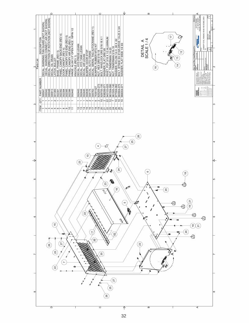
Part
s L
ist
ITE
MQ
TY
PA
RT
NU
MB
ER
DE
SC
RIP
TIO
N
11
300
04
1D
EC
AL,
WA
RN
ING
FA
N G
UA
RD
(N
OT
SH
OW
N)
21
300
04
2 D
EC
AL
, W
AR
NIN
G C
ON
NE
CT
AIR
(N
OT
SH
OW
N)
31
300
04
8D
EC
AL,
DIR
EC
TIO
N O
F R
OT
AT
ION
(N
OT
SH
OW
N)
41
300
91
3D
EC
AL,
OIL
DR
AIN
52
301
38
3L
AT
CH
, B
UL
LE
T
61
302
39
1B
AS
E, F
RA
ME
(R
EV
5)
71
302
39
2P
AN
EL,
CA
NO
PY
BA
CK
-EN
D (
RE
V 4
)
81
302
39
4D
OO
R,
CA
NO
PY
(R
EV
4)
91
302
39
5
PA
NE
L,
CA
NO
PY
HY
D E
ND
(R
EV
6)
10
13
02
39
6P
AN
EL,
CA
NO
PY
AIR
EN
D (
RE
V 3
)11
13
02
44
2H
ING
E,
AL
UM
3.0
" O
PE
N F
AC
E .1
8P
IN 1
/2
KN
UC
KL
E (
RE
V 1
)
12
13
02
44
3D
EC
AL,
HY
D P
RE
SS
LE
XA
N
13
13
02
44
4D
EC
AL,
HY
D T
AN
K L
EX
AN
14
13
02
44
5D
EC
AL,
AIR
LE
XA
N
15
23
02
63
9B
UM
PE
R, D
OO
R S
TO
P16
23
04
17
5D
EC
AL,
AU
TO
CR
AN
E
17
13
05
76
3D
EC
AL,
SE
RIA
L T
AG
AU
TO
CR
AN
E (
RE
V 1
)
18
67
63
91
52
7B
UM
PE
R, R
UB
BE
R M
TG
KIT
19
29
25
20
5-2
73
NU
T,
HE
X G
R5
5/1
6-1
8
20
10
929
70
5-1
00
BO
LT
, W
HIZ
LO
CK
GR
5 5
/16
-18
X 1
21
29
38
20
6-0
71
WA
SH
ER
, F
LA
T G
R8
3/8
22
22
943
10
3-0
25
RIV
ET
, P
OP
3/1
6 X
1/2
AL
UM
INU
M
23
12
961
50
4-0
90
NU
T,
TIN
NE
RM
AN
1/4
-20
24
79
61
50
5-1
40
NU
T,
TIN
NE
RM
AN
5/1
6-1
825
10
977
00
4-0
62
WA
SH
ER
, N
YLO
N 1
/4 X
.0
6 X
.6
2
26
10
983
90
4-0
75
BO
LT
, B
TN
HD
SS
ST
AR
-DR
IVE
1/4
-20
X 3
/4
27
10
984
00
4-0
71
WA
SH
ER
, F
LA
T W
IDE
1/4
SS
23
10
23
5
16
22
11
15
27
25
26
27
25
26
20
20
7
22
22
23
6
20
18
20
19
21
19
21
17
12
13
16
24
4
27
25
26
14

33
1 1
2 2
3 3
4 4
5 5
6 6
7 7
8 8
AA
BB
CC
DD
SIZ
ED
WG
NO
RE
V
SC
ALE
SH
EE
TO
F
DR
AW
N
PA
TH
TIT
LE
CH
EC
KE
D
MA
TE
RIA
L
TH
IS D
RA
WIN
G A
ND
AL
LIN
FO
RM
AT
ION
TH
ER
EIN
IS
TH
E P
RO
PE
RT
Y O
F A
UT
O-
CR
AN
E, IS
CO
N-
FID
EN
TIA
L A
ND
MU
ST
NO
T
BE
MA
DE
PU
BLIC
OR
CO
PIE
D. IT
IS
LO
AN
ED
SU
BJE
CT
TO
RE
TU
RN
UP
ON
DE
MA
ND
, IS
NO
T T
O B
E
US
ED
DIR
EC
TLY
OR
IN
-D
IRE
CT
LY
IN
AN
YW
AY
DE
-
TR
IME
NT
IAL T
O T
HE
IN
-T
ER
ES
T O
F A
UT
O C
RA
NE
.
DO
NO
T S
CA
LE
TO
LE
RA
NC
ES
UN
LE
SS
NO
TE
D
MA
CH
INE
D S
UR
FA
CE
S
NO
MIN
AL
DIM
.
0.0
00 T
O 1
.00
0
�
.01
0
1.0
01 T
O 5
.00
0
�
.01
5
5.0
01 T
O 1
0.0
00
�
.02
0
10.0
01 &
OV
ER
�
����
��������
�����������
�����������
����
/��
�����
���
�������
�
���������������
AU
TO
CR
AN
E
P.O
. B
OX
58
0697
T
ULS
A,
OK
74
15
8-0
69
7
G:\IN
VE
NT
OR
53\
Re
v.
Num
.R
ev.
Date
EN
Num
.R
ele
ase
d F
or
EL
EC
SY
S,
RS
60
AC
45
-60
-15
0 S
CI8
G (
RE
V 1
)
20
02
02
-99
9
1
1
1D
JP
C1
/6/2
00
7
10
0-2
00
K S
UB
1 =
4
Part
s L
ist
ITE
MQ
TY
PA
RT
NU
MB
ER
DE
SC
RIP
TIO
N
11
300
07
4G
AU
GE
, H
OU
RM
ET
ER
21
300
07
5S
WIT
CH
GA
UG
E, P
RE
SS
UR
E
31
300
07
6-0
04
SW
ITC
HG
AU
GE
, T
MP
4 ft
- 2
50
44
300
21
1R
ELA
Y,
PO
WE
R5
13
00
90
9-0
25
BR
EA
KE
R,
25
AM
P C
IRC
UIT
61
301
42
2S
WIT
CH
, P
RE
SS
NO
20
PS
I W
(R
EV
1)
71
301
72
2-3
69
AIR
EN
D,
SC
I8 3
.69
:1 R
AT
IO I
NT
EG
RA
TE
D
81
302
39
1B
AS
E, F
RA
ME
IN
FIN
ITY
(R
EV
5)
91
302
39
3
PA
NE
L,
GA
UG
E &
LIG
HT
S (
RE
V 4
)
10
13
02
44
9
LIG
HT
, IN
DIC
AT
ING
GR
EE
N11
23
02
45
0
LIG
HT
, IN
DIC
AT
ING
RE
D
12
13
02
48
6
BR
EA
KE
R,
PA
NE
L M
TG
RE
SE
T
13
13
02
59
1S
WIT
CH
, S
HU
TD
OW
N 1
17
LF
WIT
HO
UT
FU
SE
14
23
02
59
2
SW
ITC
H,
N O
MO
ME
NT
AR
Y S
PS
T
15
13
02
60
8B
RA
CK
ET
, R
EL
AY
MT
G (
RE
V 5
)
16
13
02
67
8
BR
AC
KE
T,
RE
LA
Y H
OL
DE
R (
RE
V 2
)17
13
02
78
0
TIM
ER
, R
ELA
Y 1
2V
30 S
EC
N.C
.
18
13
04
17
4D
EC
AL,
AU
TO
CR
AN
E G
AU
GE
PA
NE
L
19
29
24
20
0-1
30
NU
T,
MA
CH
#6-3
2
20
59
24
30
1-1
56
NU
T,
NY
LO
C G
R5
#8
-32
21
29
25
80
1-1
30
NU
T,
HE
X G
R5
#1
0-3
2 Z
INC
22
29
29
10
2-0
50
BO
LT
, H
EX
GR
5 #
6-3
2 X
1/2
23
39
29
70
5-1
00
BO
LT
, W
HIZ
LO
CK
GR
5 5
/16
-18
X 1
24
59
31
20
1-0
50
SC
RE
W, M
AC
H F
L H
D #
8-3
2 X
1/2
25
19
60
60
2-0
12
TE
E,
HY
D F
X F
X F
1/8
30
0P
SI
26
39
61
50
5-1
40
NU
T,
TIN
NE
RM
AN
5/1
6-1
8
27
19
80
70
4-0
12
ELB
OW
, 1/4
TU
BE
SW
VL X
1/8
MN
PT
12
14
11
1
3
2
27
25
6
23
26 14
13
9
18
21
24
5
15
22
16
20
4
17
24

34
1 1
2 2
3 3
4 4
5 5
6 6
7 7
8 8
AA
BB
CC
DD
SIZ
ED
WG
NO
RE
V
SC
ALE
SH
EE
TO
F
DR
AW
N
PA
TH
TIT
LE
CH
EC
KE
D
MA
TE
RIA
L
TH
IS D
RA
WIN
G A
ND
ALL
INF
OR
MA
TIO
N T
HE
RE
IN IS
TH
E P
RO
PE
RT
Y O
F B
OS
SIN
DU
ST
RIE
S, I
NC
., IS
CO
N-
FID
EN
TIA
L A
ND
MU
ST
NO
TB
EM
AD
E P
UB
LIC
OR
CO
PIE
D. I
T IS
LO
AN
ED
SU
BJE
CT
TO
RE
TU
RN
UP
ON
DE
MA
ND
, IS
NO
T T
O B
EU
SE
D D
IRE
CT
LY O
R IN
-D
IRE
CT
LY IN
AN
YW
AY
DE
-T
RIM
EN
TIA
L T
O T
HE
IN-
TE
RE
ST
OF
BO
SS
IND
US
-T
RIE
S, I
NC
.
DO
NO
T S
CA
LE
TO
LER
AN
CE
SU
NL
ES
S N
OT
ED
MA
CH
INE
D S
UR
FA
CE
S N
OM
INA
L D
IM.
0.00
0 TO
1.0
00
`
.010
1.00
1 TO
5.0
00
`
.015
5.0
01 T
O 1
0.00
0 `
.020
10.0
01 &
OV
ER
`.025
U UUUN NNNM MMMA AAAC CCCH HHHI IIIN NNNE EEED DDD S SSSU UUUR RRRF FFFA AAAC CCCE EEES SSS
FRACTIONAL `1
/16
DECIMAL `.03
ANGULAR `1~
G:\I
NV
EN
TO
R5
3\
Rev
. Num
.R
ev. D
ate
EN
Num
.R
ele
ased
For
OIL
/AIR
/HY
D C
LNG
SY
S, R
S60
AC
SC
I8G
(R
EV
0)
2003
39-9
99
1 1
0D
CR
H1/
30/2
007
100K
-200
K
1=4
AU
TO
CR
AN
EP
.O. B
OX
580
697
TU
LSA
, OK
741
58-0
697
Par
ts L
ist
ITE
MQ
TY
PA
RT
NU
MB
ER
DE
SC
RIP
TIO
N1
197
0508
-106
CO
NN
EC
TO
R, 1
/2 M
JIC
X -
12 M
SA
E2
197
0512
-106
CO
NN
EC
TO
R, 3
/4 M
JIC
X -
12 M
SA
E3
130
2570
CO
OLE
R, C
OM
PR
/HY
D/A
IR 3
0 X
16
41
3020
87B
ULB
WE
LL, 5
/8 U
NF
X 1
/2 N
PT
51
3023
97
BO
X, C
LR S
HR
OU
D IN
FIN
ITY
(R
EV
2)
611
9297
05-1
00B
OLT
, WH
IZLO
CK
GR
5 5/
16-1
8 X
17
498
3904
-075
BO
LT, B
TN
HD
SS
ST
AR
-DR
IVE
1/4
-20
X 3
/48
493
8004
-062
WA
SH
ER
, LO
C G
R5
1/4
94
9615
04-0
90N
UT
, TIN
NE
RM
AN
1/4
-20
101
3026
23F
AN
AS
SY
, 302
622
W/W
EA
TH
ER
PA
CK
CO
NN
EC
TO
R11
296
0108
-075
CO
NN
EC
TO
R, 1
/2 M
JIC
X 3
/4 M
NP
T12
196
0208
-050
ELB
OW
, 1/2
JIC
X 1
/2 M
NP
T13
198
4112
-050
E
LBO
W, H
YD
3/4
MN
PT
X 1
/2 M
NP
T14
190
7215
-020
CO
UP
LIN
G, P
IPE
1/2
GA
L 15
0 P
SI
151
8005
6-13
-12
KIT
, HY
D V
ALV
E B
LOC
K 1
3GP
M F
LOW
CO
NT
RO
L16
230
0444
-015
T
AP
E, 1
/16
X 1
/2 X
15
IN C
LOS
ED
CE
LLO
172
3004
44-0
06T
AP
E, 1
/16
X 1
/2 X
6 IN
CLO
SE
D C
ELL
O18
1496
1505
-140
NU
T, T
INN
ER
MA
N 5
/16-
1819
190
2615
-020
E
LBO
W, P
IPE
SID
E O
UT
1/2
GA
L 15
0PS
I20
196
1612
-050
NIP
PLE
, HY
D H
EX
RE
D 3
/4 X
1/2
214
9386
04-0
71W
AS
HE
R, F
LAT
GR
5 1/
422
292
4304
-145
NU
T, N
YLO
C G
R5
1/4-
2023
292
9104
-325
BO
LT, H
EX
GR
5 1/
4-20
X 3
1/4
241
9601
12-0
75C
ON
NE
CT
OR
, 3/4
MJI
C X
3/4
MN
PT
251
9602
12-0
75E
LBO
W, 3
/4 J
IC X
3/4
MN
PT
261
3011
42V
ALV
E, C
HE
CK
3/4
271
9841
09-0
75E
LBO
W, H
YD
3/4
MN
PT
X 3
/4 M
NP
T
18
3
18
6
5
20
17
4
12 11
26
257
10
8
7
13
2
121
23
15
21
2214
24
11
9
16
6
27
19

35
DE
TA
IL A
SC
ALE
1 /
2
DE
TA
IL B
SC
ALE
1 /
2
1 1
2 2
3 3
4 4
5 5
6 6
7 7
8 8
AA
BB
CC
DD
SIZ
ED
WG
NO
RE
V
SC
ALE
SH
EE
TO
F
DR
AW
N
PA
TH
TIT
LE
CH
EC
KE
D
MA
TE
RIA
L
TH
IS D
RA
WIN
G A
ND
ALL
INF
OR
MA
TIO
N T
HE
RE
IN IS
TH
E P
RO
PE
RT
Y O
F B
OS
SIN
DU
ST
RIE
S, I
NC
., IS
CO
N-
FID
EN
TIA
L A
ND
MU
ST
NO
TB
EM
AD
E P
UB
LIC
OR
CO
PIE
D. I
T IS
LO
AN
ED
SU
BJE
CT
TO
RE
TU
RN
UP
ON
DE
MA
ND
, IS
NO
T T
O B
EU
SE
D D
IRE
CT
LY O
R IN
-D
IRE
CT
LY IN
AN
YW
AY
DE
-T
RIM
EN
TIA
L T
O T
HE
IN-
TE
RE
ST
OF
BO
SS
IND
US
-T
RIE
S, I
NC
.
DO
NO
T S
CA
LE
TO
LER
AN
CE
SU
NL
ES
S N
OT
ED
MA
CH
INE
D S
UR
FA
CE
S N
OM
INA
L D
IM.
0.00
0 TO
1.0
00
`
.010
1.00
1 TO
5.0
00
`
.015
5.0
01 T
O 1
0.00
0 `
.020
10.0
01 &
OV
ER
`.025
U UUUN NNNM MMMA AAAC CCCH HHHI IIIN NNNE EEED DDD S SSSU UUUR RRRF FFFA AAAC CCCE EEES SSS
FRACTIONAL `1
/16
DECIMAL `.03
ANGULAR `1~
G:\I
NV
EN
TO
R5
3\
Rev
. Num
.R
ev. D
ate
EN
Num
.R
ele
ased
For
CO
MP
R &
MT
G S
YS
, R
S60
AC
45/
60/1
50 S
CI8
G
(RE
V 2
)
2003
38-9
99
1 1
2D
CR
H1/
30/2
007
100K
-200
K
1=4
AU
TO
CR
AN
EP
.O. B
OX
580
697
TU
LSA
, OK
741
58-0
697
AU
TO
CR
AN
EP
.O. B
OX
580
697
TU
LSA
, OK
741
58-0
697
Par
ts L
ist
ITE
MQ
TY
PA
RT
NU
MB
ER
DE
SC
RIP
TIO
N1
130
1722
-369
AIR
EN
D, S
CI8
3.6
9:1
RA
TIO
INT
EG
RA
TE
D2
130
2391
BA
SE
, FR
AM
E IN
FIN
ITY
(R
EV
5)
31
9705
12-1
06C
ON
NE
CT
OR
, 3/4
MJI
C X
-12
MS
AE
44
9389
08-1
80W
AS
HE
R, F
LAT
8M
M5
130
2551
AD
AP
TE
R, S
CI8
G IN
LET
VA
LVE
/TM
AR
WR
EG
64
9293
08-4
50B
OLT
, SO
C H
D 8
MM
X 4
5MM
GR
10.
97
130
2453
G
AS
KE
T, I
NLE
T V
ALV
E S
CI8
G/T
MA
R8
297
0608
-050
ELB
OW
, HY
D 1
/2 M
BS
PP
X 1
/2 M
JIC
94
9293
10-2
50B
OLT
, SO
C H
D 1
0MM
X 2
5MM
GR
10.
910
893
8810
-220
WA
SH
ER
, LO
C 1
0MM
1112
9389
10-2
00W
AS
HE
R, F
LAT
10M
M12
130
2309
AD
AP
TE
R, H
YD
MO
TO
R T
O C
OM
PR
SC
I8G
R28
(R
EV
1)
131
7555
00-0
11H
UB
, CO
UP
LIN
G 2
5MM
X8X
7 K
YW
YR
28-0
2ST
L14
175
5500
-012
HU
B, C
OU
PLI
NG
3/4
RO
UN
D W
3/1
6 K
YW
Y R
28-0
3S
TL
151
7555
00-0
07S
PID
ER
, CO
UP
LIN
G R
28-0
2 98
SH
R R
ED
161
7555
00-0
10M
OT
OR
, 1.5
8 C
IR S
AE
"A
" 3/
4 R
OU
ND
SID
E P
OR
T17
292
9806
-150
BO
LT, H
EX
GR
8 3/
8-16
X 1
1/2
182
9255
06-1
98N
UT
, NY
LOC
GR
8 3/
8-16
191
9808
04-0
12T
EE
, MB
2-
1/4
TU
BE
SW
VL
X 1
/8 M
NP
T20
230
1421
SW
ITC
H, P
RE
SS
UR
E N
.C.
212
9607
02-0
12E
LBO
W, H
YD
1/8
FN
PT
X M
NP
T S
TR
EE
T22
130
2359
F
LOA
T, O
IL L
EV
EL
NC
231
9807
04-0
12E
LBO
W, 1
/4 T
UB
E S
WV
L X
1/8
MN
PT
243
9806
04-0
12C
ON
NE
CT
OR
, TU
BE
1/4
PA
R X
1/8
NP
T25
298
0704
-025
ELB
OW
, 1/4
TU
BE
SW
VL
X 1
/4 M
NP
T26
130
2428
IN
DIC
AT
OR
, AIR
FLT
R S
RV
15H
2O27
130
2398
B
RA
CK
ET
, OIL
LE
VE
L S
WIT
CH
INF
INIT
Y (
RE
V 1
)28
292
9705
-125
BO
LT, W
HIZ
LOC
K G
R5
5/16
-18
X 1
1/4
296
3017
13
SP
AC
ER
, .44
X .5
(R
EV
2)
304
9292
10-4
00B
OLT
, HE
X 1
0MM
X 4
0MM
GR
10.
931
296
0402
-012
NIP
PLE
, HY
D H
EX
1/8
321
3018
27V
ALV
E, B
LOW
DO
WN
1/4
N.C
. 555
0233
198
0704
-025
ME
LBO
W, 1
/4 T
UB
E S
WV
L X
1/4
MN
PT
W/H
OLE
341
3019
39
SO
LEN
OID
, N.O
. AIR
351
3009
04
SW
ITC
H, P
RE
SS
UR
E F
UR
NA
S36
196
1902
-012
TE
E, M
B 1
/8 F
X 1
/8 F
X 1
/8 M
371
9608
02-0
12E
LBO
W, P
IPE
45°
ST
RE
ET
1/8
381
9616
04-0
12N
IPP
LE, H
YD
HE
X R
ED
1/4
X 1
/839
230
2634
FIT
TIN
G, B
AR
B 1
/2 N
PT
X 1
/2 H
OS
E40
130
2632
E
LBO
W, 1
/2 N
PT
SW
X 1
/2 N
PT
90°
412
3000
33-0
75C
LAM
P, A
IR IN
LET
HO
SE
3/4
WO
RM
GE
AR
421
3026
33V
ALV
E, M
INI B
ALL
1/2
NP
T43
130
2631
A
DA
PT
ER
, 1/2
BS
PP
X 1
/2 N
PT
441
9619
04-0
25T
EE
, MB
1/4
F X
1/4
F X
1/4
M45
190
7600
-005
BU
SH
ING
, RE
D 1
/4 X
1/8
GA
L46
297
0802
-012
AD
AP
TE
R, 1
/8 M
BS
PP
X 1
/8 F
NP
T47
330
1960
-025
-012
TU
BE
, PA
RA
FLE
X 1
/4 O
D X
.040
WA
LL X
12
LON
G48
130
1960
-025
-035
TU
BE
, PA
RA
FLE
X 1
/4 O
D X
.040
WA
LL X
35
LON
G49
130
1960
-025
-007
TU
BE
, PA
RA
FLE
X 1
/4 O
D X
.040
WA
LL X
7"
LON
G50
296
1505
-140
NU
T, T
INN
ER
MA
N 5
/16-
1851
6 in
3026
36H
OS
E, 1
/2 O
IL D
RA
IN52
197
0408
-088
ELB
OW
, HY
D 1
/2 M
JIC
X -
10 M
SA
E53
190
6030
-020
CA
P, P
IPE
HE
X 1
/2 Z
INC
541
3019
77O
RIF
ICE
, BLO
WD
OW
N 1
/4 P
LUG
W/5
/64
HO
LE55
130
5624
PLU
G, P
IPE
1/8
BS
PP
HE
X D
RIV
E56
196
0508
-050
ELB
OW
, HY
D 1
/2 M
NP
T X
1/2
MN
PT
Par
ts L
ist
ITE
MQ
TY
PA
RT
NU
MB
ER
DE
SC
RIP
TIO
N57
196
4808
-050
TE
E, P
IPE
1/2
F X
1/2
M X
1/2
F58
130
3815
VA
LVE
, CH
EC
K 1
/2
Par
ts L
ist
ITE
MQ
TY
PA
RT
NU
MB
ER
DE
SC
RIP
TIO
N59
196
0208
-050
ELB
OW
, 1/2
JIC
X 1
/2 M
NP
T60
196
1608
-025
NIP
PLE
, HY
D H
EX
RE
D 1
/2 X
1/4
NS
1 G
AL
3002
14LU
BE
, CO
MP
R F
LUID
AT
F
A
B
NO
TE
:-IT
EM
ES
49,
50
& 5
1 A
RE
NO
T S
HO
WN
.
6
4 5 21
1
1315
1412
11
9
3
2
222740
42
39
41
39
43
23
44
45
20
37
3254
46
2419
36
24
34
31
46
8
27
50 22
50
51
52
8
53
25
24
3560
57
59 58
56
3121
26
25 38
20
10
41
16
7 33
11
11
10
1718
55
55
30
29
29
28

36
RECOMMENDED SPARE PARTS LIST
REBMUNTRAP NOITPIRCSED YTQ
100-005557 8ICSRETLIFLIO,TNEMELE 1
200-005557 8/7ICSRETLIFRIA,TNEMELE 1
300-005557 8ICSNO-NIPS,RECSELAOC 1
400-005557 RIAPERROTALUGER,TIK 1
500-005557 G8ICSRIAPERLAESTFAHS,TIK 1
600-005557 8/7ICSTELNI,EVLAV 1
700-005557 GNILPUOC,REDIPS 1
800-005557 RIAPERLAESTFAHSROTOMDYH,TIK 1
900-005557 8ICSLAMREHT,EVLAV 1
010-005557 OR4/3"A"EASRIC85.1,ROTOM 1
110-005557 82RYWYK7X8XMM52GNILPUOC,BUH 1
210-005557 61/3WDNUOR4/3GNILPUOC,BUH 1

37
DATE: _______________
1. Information given by: 2. Information received by: 3. Has anyone helped you: Yes No
4. Distributor: 5. End-User: 6. Phone Number: 7. Make and Model for PTO: 8. AUTO CRANE Serial #: 9. Make and Model of Engine:10. Engine:11. Transmission:
12. Nature of Problem:
13. Engine RPM:14. Compressor RPM:15. Action Taken:
ADDITIONAL COMMENTS:
SERVICE QUESTIONNAIRE

38
Instructional Procedures for the Installation of AUTOCRANE INFINITY Geared Rotary Screw Air
Compressor
This air compressor should be installed only by those who have been trained and delegated to doso and who have read and understand both the operators’ manual and the installation manual.Failure to follow the instructions, procedures, and safety precautions in this manual may result inaccidents and injuries.
Install, use, and operate this air compressor only in full compliance with all pertinent O.S.H.A.requirements and all pertinent Federal, State, and Local codes or requirements and with AUTOCRANE instructions.
Do not modify this compressor except with written factory approval.
1. MOUNTING COMPRESSORWhen mounting the compressor care should be taken to ensure that its location does not impedethe operation of other components on the vehicle. For example, if your vehicle is equipped with acrane, you must make sure the compressor will not interfere with the swing of the crane. Inaddition, the compressor should be installed in an area that permits cool ambient air to enter theair filter and the hot air from the cooler to exhaust without recirculating into the air filter. One lastconsideration in the mounting should be the routing of hoses and electrical wires. The framemounting holes are shown below and the unit should be secured to the vehicle with 3/8 inch grade8 bolts, washers should be used on the mounting surface. Hardware supplyed with unit, may notwork in all applications.
+12V POWER (16 GA. YELLOW)
SPEED CONTROL OUT (16 GA. ORANGE)
GROUND (14 GA. BLACK)
+12V POWER (14GA. RED)
17.7511.42
6.42 22.6632.25
9.59
7/16" DIA.
6-PLACES
TRUCK MOUNTING SURFACE

39
INSTRUCTIONAL PROCEDURES
2. INSTALLING THE WIRING & CONNECTING THE HYDRAULIC HOSES
This unit is shipped from the factory with all necessary internal wiring installed. The only remain-ing wiring necessary is the wiring needed to interface your vehicle/power source with the AUTOCRANE compressor. (Please refer to drawing 701030 on page 31) The unit is shipped with 4loose wires, they need to be connected as follows:
1. Connect red wire to switched 12 vdc power. (or 24 VDC if you have this option)2. The yellow wire should be spliced into the 12 vdc switched feed
for the on/off switchper the end-users location.(or 24 VDC if you have this option)3. Connect black wire to ground.4. The orange wire is used to activate an electronic
speed control circuit if required. Please contact the factory with engine specific information for further assistance.CONNECTING THE HOSES
The hydraulic hoses to the compressor should be connected directly to the hydraulic controlblock. The pressure “P” input line should be made from a good quality high pressure (min. 3000PSI) hydraulic hose 1/2” or 3/4” i.d. The return line to tank “T” can be made from a mediumpressure (min. 1000 PSI) hydraulic hose 3/4” i.d. Care should be taken to see that the hoses arenot installed with kinks or bends that inhibit flow of the hydraulic oil. Lack of flow could result indamage to the motor and compressor. Lastly check to make sure hoses are not in contact withsharp objects or edges that may fray, chafe or cut them over time. Secure all hoses with tie downstraps or clamps.

40
INSTRUCTIONAL PROCEDURES3. PRE-START-UP INSPECTION CHECKS
This inspection should be done prior to removing truck from bay. Final testing of the system,including checking for leaks, is to be done outside.ALL TRUCKS SHOULD BE ROAD TESTED PRIOR TO STARTING INSTALLATION TO ISOLATE ANY
PREVIOUS TRUCK PROBLEMS.I. Check sales order to verify that all compressor related items originally ordered have been
installed or are ready to ship with the truck. This would include any special filters, oils,hoses, options, etc.
II. Vacuum all areas that have metal or plastic shavings. Wipe all fingerprints off unit andvehicle.
III. Apply decals to proper location. Make sure that the area is cleaned prior to applyingdecals. All decals should have a professional appearance upon application.
IV. Check all assemblies, clamps, fittings, drivelines, angles, nuts, and bolts to ensure theyare properly tied and secured to the vehicle. This is a very critical area of inspection. Thevehicle should not be moved until this inspection has been completed.
V. Record all serial numbers for this installation.A. Vehicle V.I.N.B. Hydraulic Pump DataC. Air-End Serial NumberD. AUTO CRANE INDUSTRIES Serial NumberE. Receiver Tank Serial NumberF. Note any special applications relating to specific installations.
VI. Check all fluid levels (position the unit on a level surface so that proper amount of fluidscan be added).
A. Fuel to provide for three hours of operation.B. Transmission fluid and PTO box.C. Compressor. Check the compressor oil sump level (see lubricant section of the operator and parts section for type of lubricant to use). 1. Add oil if needed. 2. Additional oil may need to be added after test. 3. Top off oil level to half the sightglass when finished with the test.
D. Any other applicable fluids.
4. INITIAL START-UP AND TEST
A. Start power source and allow for warm-up.B. Read the operation section in the operator and parts manual carefully before proceeding onto
the initial start-up.
41
INSTRUCTIONAL PROCEDURESC. Engage hydraulic system. A direction of rotation arrow is attached to the compressor pack-
age above the hydraulic coupling. The coupling/hub must be rotating in the direction thearrow is pointing. If for any reason this arrow has been removed the correct compressorrotation is clockwise when looking directly at the compressor shaft. Check the direction ofrotation by quickly engaging and then disengaging the compressor.
CAUTIONDO NOT RUN THE COMPRESSOR IN A REVERSE ROTATION FOR PERIODS LONGER
THAN 5 SECONDS. CONTINUED OPERATION IN THIS MANNER WILL RESULT INEXTENSIVE COMPRESSOR UNIT DAMAGE.
The safety shutdown switch should be wired in series with the solenoid that opens the flow ofthe hydraulic oil to the compressor drive motor. In cases of high temperature and/or pressure,the closing of the valve will stop the compressor operation.
Safety circuit testing for RS60AC
Safety circuit testing can be done in the following manner. Start the truck. Engage the com-pressor. Take a screwdriver and touch the 1/16” allen head screw on the face of the tempera-ture gauge and simultaneously touch the outside ring on the face of the gauge. This should shutoff the power to the solenoid of the hydraulics. Push the button in on the shutdown switch toreset. Repeat the test with the pressure gauge if solenoid does not stop flow to compressor,check wiring.