model pury-m200-300ynw-a (-bs) pury-em200-300ynw-a (-bs) · for detail, refer to the section in the...
TRANSCRIPT

PURY-M200-300YNW-A (-BS)PURY-EM200-300YNW-A (-BS)
MODEL
AIR CONDITIONING SYSTEMS

MEES17K104
GENERAL LINE-UP GENERAL LINE-UP
I.GENERAL LINE-UP
Heat Recovery R2-Series
Heat Recovery High efficiency R2-Series
PURY-M300YNW-A(-BS)PURY-M250YNW-A(-BS)PURY-M200YNW-A(-BS)
8, 10, 12HP
PURY-EM300YNW-A(-BS)PURY-EM250YNW-A(-BS)PURY-EM200YNW-A(-BS)
8, 10, 12HP
body1.fm 1 ページ 2018年4月10日 火曜日 午前10時7分

PURY-M-YNW-A, PURY-EM-YNW-A
MEES17K104 1
CONTENTS R2-Series
I.R2-Series
1. SPECIFICATIONS.................................................................................................................................... 2
2. EXTERNAL DIMENSIONS ....................................................................................................................... 8
3. CENTER OF GRAVITY ............................................................................................................................ 12
4. ELECTRICAL WIRING DIAGRAMS ......................................................................................................... 13
5. SOUND LEVELS ...................................................................................................................................... 14
5-1. Sound levels in cooling mode .......................................................................................................... 145-2. Sound levels in heating mode.......................................................................................................... 16
6. VIBRATION LEVEL .................................................................................................................................. 18
7. OPERATION TEMPERATURE RANGE................................................................................................... 19
8. CAPACITY TABLES ................................................................................................................................. 20
8-1. Correction by temperature ............................................................................................................... 208-2. Correction by total indoor................................................................................................................. 288-3. Correction by piping length .............................................................................................................. 308-4. Correction at frost and defrost ......................................................................................................... 318-5. Correction by antifreeze solution concentration............................................................................... 32
9. ELECTRICAL WORK................................................................................................................................ 33
9-1. Power supply for Outdoor unit ......................................................................................................... 339-2. Power cable specifications .............................................................................................................. 349-3. Power supply examples................................................................................................................... 35
10.M-NET CONTROL ................................................................................................................................... 36
10-1.Address setting................................................................................................................................ 36
11.PIPING DESIGN ...................................................................................................................................... 37
11-1.R32 Piping material ......................................................................................................................... 3711-2.Piping Design .................................................................................................................................. 3811-3.Refrigerant charging calculation ...................................................................................................... 4711-4.Water piping .................................................................................................................................... 48
0000004760.BOOK 1 ページ 2018年4月26日 木曜日 午後4時31分

MEES17K104
PU
RY
-M-Y
NW
-A, E
M-Y
NW
-A
2
1. SPECIFICATIONS R2-Series
I.R2-Series1. SPECIFICATIONS
Model PURY-M200YNW-A (-BS)
Power source 3-phase 4-wire 380-400-415 V 50/60 Hz
Cooling capacity *1 kW 22.4
(Nominal) kcal/h 20,000
BTU/h 76,400
Power input kW 6.85
Current input A 11.5-10.9-10.5
EER kW/kW 3.27
Temp. range of Indoor W.B. 15.0~24.0°C (59~75°F)
cooling *3 Outdoor D.B. -5.0~52.0°C (23~126°F)
Heating capacity *2 kW 25.0
(Nominal) kcal/h 21,500
BTU/h 85,300
Power input kW 6.94
Current input A 11.7-11.1-10.7
COP kW/kW 3.60
Temp. range of Indoor D.B. 15.0~27.0°C (59~81°F)
heating *3 Outdoor W.B. -20.0~15.5°C (-4~60°F)
Indoor unit Total capacity 50~150% of outdoor unit capacity
connectable Model/Quantity WP10~WP125/1~30
Sound pressure level (measured in anechoic room) *4 dB <A> 59.0/59.0
Sound power level (measured in anechoic room) *4 dB <A> 76.0/78.0
Refrigerant High pressure mm (in.) 15.88 (5/8) Brazed
piping diameter Low pressure mm (in.) 19.05 (3/4) Brazed
FAN Type x Quantity Propeller fan x 1
Air flow rate m3/min 170
L/s 2,833
cfm 6,003
Control, Driving mechanism Inverter-control, Direct-driven by motor
Motor output kW 0.92 x 1
*5 External static press. 0 Pa (0 mmH2O)
Compressor Type Inverter scroll hermetic compressor
Manufacture AC&R Works, MITSUBISHI ELECTRIC CORPORATION
Starting method Inverter
Motor output kW 6.0
Case heater kW - (- V)
Lubricant MEL46EH
External finish Pre-coated galvanized steel sheets (+powder coating for -BS type)
<MUNSELL 5Y 8/1 or similar>
External dimension H x W x D mm 1,858 (1,798 without legs) x 920 x 740
in. 73-3/16 (70-13/16 without legs) x 36-1/4 x 29-3/16
Protection devices High pressure protection High pressure sensor, High pressure switch at 4.15 MPa (601 psi)
Inverter circuit (COMP./FAN) Over-heat protection, Over-current protection
Compressor -
Fan motor -
Refrigerant Type x original charge R32 x 5.2 kg (12 lbs)
Control HBC controller
Net weight kg (lbs) 231 (510)
Heat exchanger Salt-resistant cross fin & copper tube
HIC circuit (HIC: Heat Inter-Changer) -
Defrosting method Auto-defrost mode (Reversed refrigerant cycle, Hot gas)
Drawing External WKL94L647
Wiring WKE94G951
Standard attachment Document Installation Manual
Accessory -
Optional parts
Main HBC controller: CMB-WM108,1016V-AA
Sub HBC controller: CMB-WM108,1016V-AB
Remarks Details on foundation work, duct work, insulation work, electrical wiring, power source switch, and other items shall be referred to the Installation Manual.Due to continuing improvement, above specifications may be subject to change without notice.
Notes: Unit converter
1.Nominal cooling conditions (subject to JIS B8615-2) Indoor: 27°CD.B./19°CW.B. (81°FD.B./66°FW.B.), Outdoor: 35°CD.B. (95°FD.B.) Pipe length: 7.5 m (24-9/16 ft.), Level difference: 0 m (0 ft.)2.Nominal heating conditions (subject to JIS B8615-2) Indoor: 20°CD.B. (68°FD.B.), Outdoor: 7°CD.B./6°CW.B. (45°FD.B./43°FW.B.) Pipe length: 7.5 m (24-9/16 ft.), Level difference: 0 m (0 ft.) 3.-5°CD.B. (23°FD.B.)/-6°CW.B. (21°FW.B.) to 21°CD.B. (70°FD.B.)/15.5°CW.B. (60°FW.B.) with cooling/heating mixed operation. 4.Cooling mode/Heating mode 5.External static pressure option is available (30 Pa, 60 Pa, 80 Pa/3.1 mmH2O, 6.1 mmH2O, 8.2 mmH2O). Consult your dealer about the specification when setting External static pressure option. 6.R32 is flammable, and certain restrictions apply to the installation of units. When installing new units, moving the existing units, or changing the layout of the room, ensure that installation restrictions are observed. For detail, refer to the section in the Databook on installation restrictions.
BTU/h =kW x 3,412
cfm =m3/min x 35.31
lbs =kg/0.4536
*Above specification data is subject to rounding variation.
0000004760.BOOK 2 ページ 2018年4月26日 木曜日 午後4時31分

MEES17K104
PU
RY
-M-Y
NW
-A, E
M-Y
NW
-A
3
1. SPECIFICATIONS R2-Series
Model PURY-M250YNW-A (-BS)
Power source 3-phase 4-wire 380-400-415 V 50/60 Hz
Cooling capacity *1 kW 28.0
(Nominal) kcal/h 25,000
BTU/h 95,500
Power input kW 9.92
Current input A 16.7-15.9-15.3
EER kW/kW 2.82
Temp. range of Indoor W.B. 15.0~24.0°C (59~75°F)
cooling *3 Outdoor D.B. -5.0~52.0°C (23~126°F)
Heating capacity *2 kW 31.5
(Nominal) kcal/h 27,100
BTU/h 107,500
Power input kW 10.06
Current input A 16.9-16.1-15.5
COP kW/kW 3.13
Temp. range of Indoor D.B. 15.0~27.0°C (59~81°F)
heating *3 Outdoor W.B. -20.0~15.5°C (-4~60°F)
Indoor unit Total capacity 50~150% of outdoor unit capacity
connectable Model/Quantity WP10~WP125/1~37
Sound pressure level (measured in anechoic room) *4 dB <A> 60.5/61.0
Sound power level (measured in anechoic room) *4 dB <A> 78.5/80.0
Refrigerant High pressure mm (in.) 15.88 (5/8) Brazed
piping diameter Low pressure mm (in.) 19.05 (3/4) Brazed
FAN Type x Quantity Propeller fan x 1
Air flow rate m3/min 185
L/s 3,083
cfm 6,532
Control, Driving mechanism Inverter-control, Direct-driven by motor
Motor output kW 0.92 x 1
*5 External static press. 0 Pa (0 mmH2O)
Compressor Type Inverter scroll hermetic compressor
Manufacture AC&R Works, MITSUBISHI ELECTRIC CORPORATION
Starting method Inverter
Motor output kW 7.5
Case heater kW - (- V)
Lubricant MEL46EH
External finish Pre-coated galvanized steel sheets (+powder coating for -BS type)
<MUNSELL 5Y 8/1 or similar>
External dimension H x W x D mm 1,858 (1,798 without legs) x 920 x 740
in. 73-3/16 (70-13/16 without legs) x 36-1/4 x 29-3/16
Protection devices High pressure protection High pressure sensor, High pressure switch at 4.15 MPa (601 psi)
Inverter circuit (COMP./FAN) Over-heat protection, Over-current protection
Compressor -
Fan motor -
Refrigerant Type x original charge R32 x 5.2 kg (12 lbs)
Control HBC controller
Net weight kg (lbs) 231 (510)
Heat exchanger Salt-resistant cross fin & copper tube
HIC circuit (HIC: Heat Inter-Changer) -
Defrosting method Auto-defrost mode (Reversed refrigerant cycle, Hot gas)
Drawing External WKL94L647
Wiring WKE94G951
Standard attachment Document Installation Manual
Accessory -
Optional parts
Main HBC controller: CMB-WM108,1016V-AA
Sub HBC controller: CMB-WM108,1016V-AB
Remarks Details on foundation work, duct work, insulation work, electrical wiring, power source switch, and other items shall be referred to the Installation Manual.Due to continuing improvement, above specifications may be subject to change without notice.
Notes: Unit converter
1.Nominal cooling conditions (subject to JIS B8615-2) Indoor: 27°CD.B./19°CW.B. (81°FD.B./66°FW.B.), Outdoor: 35°CD.B. (95°FD.B.) Pipe length: 7.5 m (24-9/16 ft.), Level difference: 0 m (0 ft.)2.Nominal heating conditions (subject to JIS B8615-2) Indoor: 20°CD.B. (68°FD.B.), Outdoor: 7°CD.B./6°CW.B. (45°FD.B./43°FW.B.) Pipe length: 7.5 m (24-9/16 ft.), Level difference: 0 m (0 ft.) 3.-5°CD.B. (23°FD.B.)/-6°CW.B. (21°FW.B.) to 21°CD.B. (70°FD.B.)/15.5°CW.B. (60°FW.B.) with cooling/heating mixed operation. 4.Cooling mode/Heating mode 5.External static pressure option is available (30 Pa, 60 Pa, 80 Pa/3.1 mmH2O, 6.1 mmH2O, 8.2 mmH2O). Consult your dealer about the specification when setting External static pressure option. 6.R32 is flammable, and certain restrictions apply to the installation of units. When installing new units, moving the existing units, or changing the layout of the room, ensure that installation restrictions are observed. For detail, refer to the section in the Databook on installation restrictions.
BTU/h =kW x 3,412
cfm =m3/min x 35.31
lbs =kg/0.4536
*Above specification data is subject to rounding variation.
0000004760.BOOK 3 ページ 2018年4月26日 木曜日 午後4時31分

MEES17K104
PU
RY
-M-Y
NW
-A, E
M-Y
NW
-A
4
1. SPECIFICATIONS R2-Series
Model PURY-M300YNW-A (-BS)
Number of HBC controller Single HBC Double HBC
Power source 3-phase 4-wire 380-400-415 V 50/60 Hz
Cooling capacity *1 kW 33.5
(Nominal) kcal/h 30,000
BTU/h 114,300
Power input kW 13.08 11.09
Current input A 22.0-20.9-20.2 18.7-17.7-17.1
EER kW/kW 2.56 3.02
Temp. range of Indoor W.B. 15.0~24.0°C (59~75°F)
cooling *3 Outdoor D.B. -5.0~52.0°C (23~126°F)
Heating capacity *2 kW 37.5
(Nominal) kcal/h 32,300
BTU/h 128,000
Power input kW 12.45 11.68
Current input A 21.0-19.9-19.2 19.7-18.7-18.0
COP kW/kW 3.01 3.21
Temp. range of Indoor D.B. 15.0~27.0°C (59~81°F)
heating *3 Outdoor W.B. -20.0~15.5°C (-4~60°F)
Indoor unit Total capacity 50~150% of outdoor unit capacity
connectable Model/Quantity WP10~WP125/2~45
Sound pressure level (measured in anechoic room) *4 dB <A> 61.0/67.0
Sound power level (measured in anechoic room) *4 dB <A> 80.0/86.5
Refrigerant High pressure mm (in.) 15.88 (5/8) Brazed
piping diameter Low pressure mm (in.) 19.05 (3/4) Brazed
FAN Type x Quantity Propeller fan x 1
Air flow rate m3/min 240
L/s 4,000
cfm 8,474
Control, Driving mechanism Inverter-control, Direct-driven by motor
Motor output kW 0.92 x 1
*5 External static press. 0 Pa (0 mmH2O)
Compressor Type Inverter scroll hermetic compressor
Manufacture AC&R Works, MITSUBISHI ELECTRIC CORPORATION
Starting method Inverter
Motor output kW 8.5
Case heater kW - (- V)
Lubricant MEL46EH
External finish Pre-coated galvanized steel sheets (+powder coating for -BS type)
<MUNSELL 5Y 8/1 or similar>
External dimension H x W x D mm 1,858 (1,798 without legs) x 920 x 740
in. 73-3/16 (70-13/16 without legs) x 36-1/4 x 29-3/16
Protection devices High pressure protection High pressure sensor, High pressure switch at 4.15 MPa (601 psi)
Inverter circuit (COMP./FAN) Over-heat protection, Over-current protection
Compressor -
Fan motor -
Refrigerant Type x original charge R32 x 5.2 kg (12 lbs)
Control HBC controller
Net weight kg (lbs) 231 (510)
Heat exchanger Salt-resistant cross fin & copper tube
HIC circuit (HIC: Heat Inter-Changer) -
Defrosting method Auto-defrost mode (Reversed refrigerant cycle, Hot gas)
Drawing External WKL94L647
Wiring WKE94G951
Standard attachment Document Installation Manual
Accessory -
Optional parts Main HBC controller: CMB-WM108,1016V-AA
Sub HBC controller: CMB-WM108,1016V-AB
Remarks Details on foundation work, duct work, insulation work, electrical wiring, power source switch, and other items shall be referred to the Installation Manual.Due to continuing improvement, above specifications may be subject to change without notice.
Notes: Unit converter
1.Nominal cooling conditions (subject to JIS B8615-2) Indoor: 27°CD.B./19°CW.B. (81°FD.B./66°FW.B.), Outdoor: 35°CD.B. (95°FD.B.) Pipe length: 7.5 m (24-9/16 ft.), Level difference: 0 m (0 ft.)2.Nominal heating conditions (subject to JIS B8615-2) Indoor: 20°CD.B. (68°FD.B.), Outdoor: 7°CD.B./6°CW.B. (45°FD.B./43°FW.B.) Pipe length: 7.5 m (24-9/16 ft.), Level difference: 0 m (0 ft.) 3.-5°CD.B. (23°FD.B.)/-6°CW.B. (21°FW.B.) to 21°CD.B. (70°FD.B.)/15.5°CW.B. (60°FW.B.) with cooling/heating mixed operation. 4.Cooling mode/Heating mode 5.External static pressure option is available (30 Pa, 60 Pa, 80 Pa/3.1 mmH2O, 6.1 mmH2O, 8.2 mmH2O). Consult your dealer about the specification when setting External static pressure option. 6.R32 is flammable, and certain restrictions apply to the installation of units. When installing new units, moving the existing units, or changing the layout of the room, ensure that installation restrictions are observed. For detail, refer to the section in the Databook on installation restrictions.
BTU/h =kW x 3,412
cfm =m3/min x 35.31
lbs =kg/0.4536
*Above specification data is subject to rounding variation.
0000004760.BOOK 4 ページ 2018年4月26日 木曜日 午後4時31分

MEES17K104
PU
RY
-M-Y
NW
-A, E
M-Y
NW
-A
5
1. SPECIFICATIONS R2-Series
Model PURY-EM200YNW-A (-BS)
Power source 3-phase 4-wire 380-400-415 V 50/60 Hz
Cooling capacity *1 kW 22.4
(Nominal) kcal/h 20,000
BTU/h 76,400
Power input kW 6.15
Current input A 10.3-9.8-9.5
EER kW/kW 3.64
Temp. range of Indoor W.B. 15.0~24.0°C (59~75°F)
cooling *3 Outdoor D.B. -5.0~52.0°C (23~126°F)
Heating capacity *2 kW 25.0
(Nominal) kcal/h 21,500
BTU/h 85,300
Power input kW 6.77
Current input A 11.4-10.8-10.4
COP kW/kW 3.69
Temp. range of Indoor D.B. 15.0~27.0°C (59~81°F)
heating *3 Outdoor W.B. -20.0~15.5°C (-4~60°F)
Indoor unit Total capacity 50~150% of outdoor unit capacity
connectable Model/Quantity WP10~WP125/1~30
Sound pressure level (measured in anechoic room) *4 dB <A> 59.0/59.0
Sound power level (measured in anechoic room) *4 dB <A> 76.0/78.0
Refrigerant High pressure mm (in.) 15.88 (5/8) Brazed
piping diameter Low pressure mm (in.) 19.05 (3/4) Brazed
FAN Type x Quantity Propeller fan x 1
Air flow rate m3/min 170
L/s 2,833
cfm 6,003
Control, Driving mechanism Inverter-control, Direct-driven by motor
Motor output kW 0.92 x 1
*5 External static press. 0 Pa (0 mmH2O)
Compressor Type Inverter scroll hermetic compressor
Manufacture AC&R Works, MITSUBISHI ELECTRIC CORPORATION
Starting method Inverter
Motor output kW 6.0
Case heater kW - (- V)
Lubricant MEL46EH
External finish Pre-coated galvanized steel sheets (+powder coating for -BS type)
<MUNSELL 5Y 8/1 or similar>
External dimension H x W x D mm 1,858 (1,798 without legs) x 920 x 740
in. 73-3/16 (70-13/16 without legs) x 36-1/4 x 29-3/16
Protection devices High pressure protection High pressure sensor, High pressure switch at 4.15 MPa (601 psi)
Inverter circuit (COMP./FAN) Over-heat protection, Over-current protection
Compressor -
Fan motor -
Refrigerant Type x original charge R32 x 5.2 kg (12 lbs)
Control HBC controller
Net weight kg (lbs) 237 (523)
Heat exchanger Salt-resistant cross fin & aluminium tube
HIC circuit (HIC: Heat Inter-Changer) -
Defrosting method Auto-defrost mode (Reversed refrigerant cycle, Hot gas)
Drawing External WKL94L648
Wiring WKE94G951
Standard attachment Document Installation Manual
Accessory -
Optional parts
Main HBC controller: CMB-WM108,1016V-AA
Sub HBC controller: CMB-WM108,1016V-AB
Remarks Details on foundation work, duct work, insulation work, electrical wiring, power source switch, and other items shall be referred to the Installation Manual.Due to continuing improvement, above specifications may be subject to change without notice.
Notes: Unit converter
1.Nominal cooling conditions (subject to JIS B8615-2) Indoor: 27°CD.B./19°CW.B. (81°FD.B./66°FW.B.), Outdoor: 35°CD.B. (95°FD.B.) Pipe length: 7.5 m (24-9/16 ft.), Level difference: 0 m (0 ft.)2.Nominal heating conditions (subject to JIS B8615-2) Indoor: 20°CD.B. (68°FD.B.), Outdoor: 7°CD.B./6°CW.B. (45°FD.B./43°FW.B.) Pipe length: 7.5 m (24-9/16 ft.), Level difference: 0 m (0 ft.) 3.-5°CD.B. (23°FD.B.)/-6°CW.B. (21°FW.B.) to 21°CD.B. (70°FD.B.)/15.5°CW.B. (60°FW.B.) with cooling/heating mixed operation. 4.Cooling mode/Heating mode 5.External static pressure option is available (30 Pa, 60 Pa, 80 Pa/3.1 mmH2O, 6.1 mmH2O, 8.2 mmH2O). Consult your dealer about the specification when setting External static pressure option. 6.R32 is flammable, and certain restrictions apply to the installation of units. When installing new units, moving the existing units, or changing the layout of the room, ensure that installation restrictions are observed. For detail, refer to the section in the Databook on installation restrictions.
BTU/h =kW x 3,412
cfm =m3/min x 35.31
lbs =kg/0.4536
*Above specification data is subject to rounding variation.
0000004760.BOOK 5 ページ 2018年4月26日 木曜日 午後4時31分

MEES17K104
PU
RY
-M-Y
NW
-A, E
M-Y
NW
-A
6
1. SPECIFICATIONS R2-Series
Model PURY-EM250YNW-A (-BS)
Power source 3-phase 4-wire 380-400-415 V 50/60 Hz
Cooling capacity *1 kW 28.0
(Nominal) kcal/h 25,000
BTU/h 95,500
Power input kW 8.77
Current input A 14.8-14.0-13.5
EER kW/kW 3.19
Temp. range of Indoor W.B. 15.0~24.0°C (59~75°F)
cooling *3 Outdoor D.B. -5.0~52.0°C (23~126°F)
Heating capacity *2 kW 31.5
(Nominal) kcal/h 27,100
BTU/h 107,500
Power input kW 9.84
Current input A 16.6-15.7-15.2
COP kW/kW 3.20
Temp. range of Indoor D.B. 15.0~27.0°C (59~81°F)
heating *3 Outdoor W.B. -20.0~15.5°C (-4~60°F)
Indoor unit Total capacity 50~150% of outdoor unit capacity
connectable Model/Quantity WP10~WP125/1~37
Sound pressure level (measured in anechoic room) *4 dB <A> 60.5/61.0
Sound power level (measured in anechoic room) *4 dB <A> 78.5/80.0
Refrigerant High pressure mm (in.) 15.88 (5/8) Brazed
piping diameter Low pressure mm (in.) 19.05 (3/4) Brazed
FAN Type x Quantity Propeller fan x 1
Air flow rate m3/min 185
L/s 3,083
cfm 6,532
Control, Driving mechanism Inverter-control, Direct-driven by motor
Motor output kW 0.92 x 1
*5 External static press. 0 Pa (0 mmH2O)
Compressor Type Inverter scroll hermetic compressor
Manufacture AC&R Works, MITSUBISHI ELECTRIC CORPORATION
Starting method Inverter
Motor output kW 7.5
Case heater kW - (- V)
Lubricant MEL46EH
External finish Pre-coated galvanized steel sheets (+powder coating for -BS type)
<MUNSELL 5Y 8/1 or similar>
External dimension H x W x D mm 1,858 (1,798 without legs) x 920 x 740
in. 73-3/16 (70-13/16 without legs) x 36-1/4 x 29-3/16
Protection devices High pressure protection High pressure sensor, High pressure switch at 4.15 MPa (601 psi)
Inverter circuit (COMP./FAN) Over-heat protection, Over-current protection
Compressor -
Fan motor -
Refrigerant Type x original charge R32 x 5.2 kg (12 lbs)
Control HBC controller
Net weight kg (lbs) 237 (523)
Heat exchanger Salt-resistant cross fin & aluminium tube
HIC circuit (HIC: Heat Inter-Changer) -
Defrosting method Auto-defrost mode (Reversed refrigerant cycle, Hot gas)
Drawing External WKL94L648
Wiring WKE94G951
Standard attachment Document Installation Manual
Accessory -
Optional parts
Main HBC controller: CMB-WM108,1016V-AA
Sub HBC controller: CMB-WM108,1016V-AB
Remarks Details on foundation work, duct work, insulation work, electrical wiring, power source switch, and other items shall be referred to the Installation Manual.Due to continuing improvement, above specifications may be subject to change without notice.
Notes: Unit converter
1.Nominal cooling conditions (subject to JIS B8615-2) Indoor: 27°CD.B./19°CW.B. (81°FD.B./66°FW.B.), Outdoor: 35°CD.B. (95°FD.B.) Pipe length: 7.5 m (24-9/16 ft.), Level difference: 0 m (0 ft.)2.Nominal heating conditions (subject to JIS B8615-2) Indoor: 20°CD.B. (68°FD.B.), Outdoor: 7°CD.B./6°CW.B. (45°FD.B./43°FW.B.) Pipe length: 7.5 m (24-9/16 ft.), Level difference: 0 m (0 ft.) 3.-5°CD.B. (23°FD.B.)/-6°CW.B. (21°FW.B.) to 21°CD.B. (70°FD.B.)/15.5°CW.B. (60°FW.B.) with cooling/heating mixed operation. 4.Cooling mode/Heating mode 5.External static pressure option is available (30 Pa, 60 Pa, 80 Pa/3.1 mmH2O, 6.1 mmH2O, 8.2 mmH2O). Consult your dealer about the specification when setting External static pressure option. 6.R32 is flammable, and certain restrictions apply to the installation of units. When installing new units, moving the existing units, or changing the layout of the room, ensure that installation restrictions are observed. For detail, refer to the section in the Databook on installation restrictions.
BTU/h =kW x 3,412
cfm =m3/min x 35.31
lbs =kg/0.4536
*Above specification data is subject to rounding variation.
0000004760.BOOK 6 ページ 2018年4月26日 木曜日 午後4時31分

MEES17K104
PU
RY
-M-Y
NW
-A, E
M-Y
NW
-A
7
1. SPECIFICATIONS R2-Series
Model PURY-EM300YNW-A (-BS)
Number of HBC controller Single HBC Double HBC
Power source 3-phase 4-wire 380-400-415 V 50/60 Hz
Cooling capacity *1 kW 33.5
(Nominal) kcal/h 30,000
BTU/h 114,300
Power input kW 11.79 10.02
Current input A 19.9-18.9-18.2 16.9-16.0-15.4
EER kW/kW 2.84 3.34
Temp. range of Indoor W.B. 15.0~24.0°C (59~75°F)
cooling *3 Outdoor D.B. -5.0~52.0°C (23~126°F)
Heating capacity *2 kW 37.5
(Nominal) kcal/h 32,300
BTU/h 128,000
Power input kW 11.46 10.90
Current input A 19.3-18.3-17.7 18.4-17.4-16.8
COP kW/kW 3.27 3.44
Temp. range of Indoor D.B. 15.0~27.0°C (59~81°F)
heating *3 Outdoor W.B. -20.0~15.5°C (-4~60°F)
Indoor unit Total capacity 50~150% of outdoor unit capacity
connectable Model/Quantity WP10~WP125/2~45
Sound pressure level (measured in anechoic room) *4 dB <A> 61.0/67.0
Sound power level (measured in anechoic room) *4 dB <A> 80.0/86.5
Refrigerant High pressure mm (in.) 15.88 (5/8) Brazed
piping diameter Low pressure mm (in.) 19.05 (3/4) Brazed
FAN Type x Quantity Propeller fan x 1
Air flow rate m3/min 240
L/s 4,000
cfm 8,474
Control, Driving mechanism Inverter-control, Direct-driven by motor
Motor output kW 0.92 x 1
*5 External static press. 0 Pa (0 mmH2O)
Compressor Type Inverter scroll hermetic compressor
Manufacture AC&R Works, MITSUBISHI ELECTRIC CORPORATION
Starting method Inverter
Motor output kW 8.5
Case heater kW - (- V)
Lubricant MEL46EH
External finish Pre-coated galvanized steel sheets (+powder coating for -BS type)
<MUNSELL 5Y 8/1 or similar>
External dimension H x W x D mm 1,858 (1,798 without legs) x 920 x 740
in. 73-3/16 (70-13/16 without legs) x 36-1/4 x 29-3/16
Protection devices High pressure protection High pressure sensor, High pressure switch at 4.15 MPa (601 psi)
Inverter circuit (COMP./FAN) Over-heat protection, Over-current protection
Compressor -
Fan motor -
Refrigerant Type x original charge R32 x 5.2 kg (12 lbs)
Control HBC controller
Net weight kg (lbs) 237 (523)
Heat exchanger Salt-resistant cross fin & aluminium tube
HIC circuit (HIC: Heat Inter-Changer) -
Defrosting method Auto-defrost mode (Reversed refrigerant cycle, Hot gas)
Drawing External WKL94L648
Wiring WKE94G951
Standard attachment Document Installation Manual
Accessory -
Optional parts Main HBC controller: CMB-WM108,1016V-AA
Sub HBC controller: CMB-WM108,1016V-AB
Remarks Details on foundation work, duct work, insulation work, electrical wiring, power source switch, and other items shall be referred to the Installation Manual.Due to continuing improvement, above specifications may be subject to change without notice.
Notes: Unit converter
1.Nominal cooling conditions (subject to JIS B8615-2) Indoor: 27°CD.B./19°CW.B. (81°FD.B./66°FW.B.), Outdoor: 35°CD.B. (95°FD.B.) Pipe length: 7.5 m (24-9/16 ft.), Level difference: 0 m (0 ft.)2.Nominal heating conditions (subject to JIS B8615-2) Indoor: 20°CD.B. (68°FD.B.), Outdoor: 7°CD.B./6°CW.B. (45°FD.B./43°FW.B.) Pipe length: 7.5 m (24-9/16 ft.), Level difference: 0 m (0 ft.) 3.-5°CD.B. (23°FD.B.)/-6°CW.B. (21°FW.B.) to 21°CD.B. (70°FD.B.)/15.5°CW.B. (60°FW.B.) with cooling/heating mixed operation. 4.Cooling mode/Heating mode 5.External static pressure option is available (30 Pa, 60 Pa, 80 Pa/3.1 mmH2O, 6.1 mmH2O, 8.2 mmH2O). Consult your dealer about the specification when setting External static pressure option. 6.R32 is flammable, and certain restrictions apply to the installation of units. When installing new units, moving the existing units, or changing the layout of the room, ensure that installation restrictions are observed. For detail, refer to the section in the Databook on installation restrictions.
BTU/h =kW x 3,412
cfm =m3/min x 35.31
lbs =kg/0.4536
*Above specification data is subject to rounding variation.
0000004760.BOOK 7 ページ 2018年4月26日 木曜日 午後4時31分

MEES17K104
PU
RY
-M-Y
NW
-A, E
M-Y
NW
-A
8
2. EXTERNAL DIMENSIONS R2-Series
2. EXTERNAL DIMENSIONS
Ser
vice
pane
l
Con
trol b
ox
13
47
Inta
keai
r
Fron
t vie
w
Inta
keai
rIn
take
air
Disc
harg
e ai
r
Rea
r vie
w
2
5
68
(Mounting pitch)
Bot
tom
vie
w(M
ount
ing
pitc
h)
2×5-
ø4.6
Hol
e(M
ake
hole
at t
he p
last
ic fa
n gu
ard
for s
now
hoo
d at
tach
men
t)<S
now
hoo
d at
tach
men
t hol
e>
Top
view
Slin
g ho
le
Deta
chab
le le
g(fr
ont a
nd b
ack,
2 p
oint
s)No
te 2
*
2×2-
14×3
1 O
val h
ole
2×2-
14×2
0 O
val h
ole(
with
out d
etac
habl
e le
g)
Inta
keai
r
Refri
gera
nt
serv
ice va
lve<H
igh p
ress
ure>
Refri
gera
nt
serv
ice va
lve<L
ow p
ress
ure>
(INV
Box
)C
ontro
l box
(MA
IN B
ox)
For t
rans
miss
ion ca
bles
For w
ires
For p
ipes
NO
.U
sage
Spe
cific
atio
ns
Fron
t thro
ugh h
oleBo
ttom
throu
gh ho
leFr
ont th
roug
h hole
Fron
t thro
ugh h
ole
Botto
m thr
ough
hole
Botto
m thr
ough
hole
Fron
t thro
ugh h
ole
148
X 84
Kno
ckou
t hol
e
ø65
or ø
40 K
nock
out h
ole
ø52
or ø
27 K
nock
out h
ole
ø65
Knoc
kout
hol
e ø5
2 Kn
ocko
ut h
ole
ø34
Knoc
kout
hol
e
150
X 94
Kno
ckou
t hol
e
Con
nect
ing
pipe
spe
cific
atio
ns
ø34
Knoc
kout
hol
e
Not
e 1.
Ple
ase
refe
r to
next
pag
e fo
r inf
orm
atio
n re
gard
ing
nece
ssar
y
s
paci
ng a
roun
d th
e un
it an
d fo
unda
tion
wor
k.
2.T
he d
etac
habl
e le
g ca
n be
rem
oved
at s
ite.
3
.At b
razi
ng o
f pip
es, w
rap
the
refri
gera
nt s
ervi
ce v
alve
with
wet
clo
th a
nd k
eep
the
tem
pera
ture
of r
efrig
eran
t
s
ervi
ce v
alve
und
er 1
20°C
.
*1 C
onne
ct th
e re
frige
rant
pip
e to
the
serv
ice
valv
e
ac
cord
ing
to th
e In
stal
latio
n M
anua
l.
Botto
m thr
ough
hole
Mod
elD
iam
eter
Ref
riger
ant p
ipe
Ser
vice
val
ve
M25
0ø2
2.2
ø15.8
8 Braz
ed *1
ø2
8.58
M20
0Hi
gh p
ress
ure
Low
pres
sure
M30
0
High
pre
ssur
eLo
w pr
essu
re
ø19.0
5 Braz
ed *1
132
207
256
148
125
90
110125
14953031798 (60)
1858
5656
2054
592
110185
681(678~684) 29.5
(740)
8076
080
166
181
152
172
216
160
243
150
128
9479181
29.5
84 71
35
920
19.5
19.5
881
740
150
600=150×4 70
5420
116 (60)
1 2 43 5 6 7 8
Left
side
vie
w
Unit: mmPURY-M200, 250, 300YNW-A(-BS)
0000004760.BOOK 8 ページ 2018年4月26日 木曜日 午後4時31分

MEES17K104
PU
RY
-M-Y
NW
-A, E
M-Y
NW
-A
9
2. EXTERNAL DIMENSIONS R2-Series
Fron
tFr
ont
<Top
vie
w>
*
<Uni
t:mm
>
*
*
*
<Top
vie
w>
**
**
M10
anc
hor b
olt
<fie
ld s
uppl
y re
quire
d>
Fixi
ng p
late
<fie
ld s
uppl
y re
quire
d>
<To be left open>
Fron
t
Wal
l <H
>
<To
be le
ft op
en>
*
Front
<Uni
t:mm
>
*
*
* *
** *
Fixi
ng p
late
<fie
ld s
uppl
y re
quire
d>
M10
anc
hor b
olt
<fie
ld s
uppl
y re
quire
d>
Wal
l <H
>
<To be left open>
<To be left open>
<To be left open>
Fron
t
Wal
l <H
>
Wal
l <H
>
Wall <H>
Wall <H>
Front
Front
<To
be le
ft op
en>
Wal
l <H
>
Fron
t
Wal
l <H
>
<To be left open>
<To be left open>
Front
Front
Front
Wal
l <H
>W
all <
H>
Fron
t
<To be left open>
<To
be le
ft op
en> Det
acha
ble
leg
Fig.
A (w
ithou
t det
acha
ble
legs
)
Fig.
B (w
ith d
etac
habl
e le
gs)
Fig.
C (w
ithou
t det
acha
ble
legs
)Fi
g.D
(with
det
acha
ble
legs
)De
tach
able
leg
* *
*
<Wal
l hei
ght l
imit>
Fro
nt :
Up
to th
e un
it he
ight
Bac
k : U
p to
the
unit
heig
ht
S
ide
: U
p to
the
uni
t hei
ght
<Sid
e vi
ew>
Front
1. R
equir
ed sp
ace
arou
nd th
e un
it
●In
case
of s
ingl
e in
stal
latio
n Se
cure
eno
ugh
spac
e ar
ound
the
unit a
s sho
wn in
the
figur
e be
low.
▪ With
a s
pace
of a
t lea
st
Whe
n th
e he
ight o
f the
wall
s on
the
front
, bac
k or o
n th
e sid
es<H
>
2. F
ound
ation
wor
kTa
ke in
to co
nside
ratio
n th
e su
rface
stre
ngth
, wat
er d
raina
ge ro
ute,
pip
ing ro
ute,
and
wirin
g ro
ute
when
pre
parin
g th
e ins
talla
tion
site.
<N
ote
that
the
drain
wat
er co
mes
out
of t
he u
nit d
uring
ope
ratio
n.>
Build
the
foun
datio
n in
such
way
that
the
corn
er o
f the
insta
llatio
n leg
is
secu
rely
supp
orte
d as
show
n in
the
right
figur
e.(F
ig.A,
B)
Whe
n us
ing a
rubb
er is
olatin
g cu
shion
, plea
se e
nsur
e it i
s lar
ge e
noug
h
to co
ver t
he e
ntire
widt
h of
eac
h of
the
unit's
legs
.Th
e pr
otru
sion
lengt
h of
the
anch
or b
olt m
ust n
ot e
xcee
d 30
mm
.(Fig.
A,B)
Use
four
fixing
plat
es a
s sho
wn in
the
right
figur
e <f
ield
supp
ly re
quire
d>
when
usin
g po
st-ins
talle
d an
chor
bolt
s.(Fi
g.C,
D)To
pre
vent
small
anim
als a
nd w
ater
and
snow
from
ent
ering
the
unit a
nd d
amag
ing its
par
ts,
close
the
gap
arou
nd th
e ed
ges o
f thr
ough
hole
s for
pipe
s and
wire
s with
fill
er p
lates
<fie
ld su
pply
requ
ired>
.W
hen
the
pipes
or c
ables
are
rout
ed a
t the
bot
tom
of t
he u
nit,
m
ake
sure
that
the
thro
ugh
hole
at th
e ba
se o
f the
unit
doe
s not
get
bloc
ked
wi
th th
e ins
talla
tion
base
.Re
fer t
o th
e In
stalla
tion
Man
ual w
hen
insta
lling
units
on
an in
stalla
tion
base
.
●In
case
of c
olle
ctiv
e in
stal
latio
n W
hen
mult
iple
units
are
insta
lled
adjac
ent t
o ea
ch o
ther
, sec
ure
enou
gh sp
ace
to a
llow
fo
r air
circu
lation
and
walk
way b
etwe
en g
roup
s of u
nits a
s sho
wn in
the
figur
es b
elow.
At le
ast t
wo si
des m
ust b
e lef
t ope
n.
As w
ith th
e sin
gle in
stalla
tion,
add
the
heigh
t tha
t exc
eeds
the
heigh
t lim
it<h>
to
the
figur
es th
at a
re m
arke
d wi
th a
n as
teris
k.
If th
ere
is a
wall a
t bot
h th
e fro
nt a
nd th
e re
ar o
f the
unit
, insta
ll up
to si
x unit
s
cons
ecut
ively
in th
e sid
e dir
ectio
n an
d pr
ovide
a sp
ace
of 1
000m
m o
r mor
e as
inlet
spac
e/
pass
age
spac
e fo
r eac
h six
unit
s.
300m
m to
the
wal
l on
the
back
of t
he u
nit
▪ With
a s
pace
of a
t lea
st
100m
m to
the
wal
l on
the
back
of t
he u
nit
exc
eeds
the
wall h
eight
limit a
s def
ined
below
add
the
heigh
t tha
t exc
eeds
the
heigh
t lim
it <h>
to th
e fig
ures
that
are
mar
ked
with
an
aste
risk.
15 m
in.
50 m
in.
50 m
in.
100 min. 450 min.
300 min.
100
min
.30
min
.45
0 m
in.
450
min
.45
0 m
in.1
00 m
in.
450 min.100 min.
450 min.
1000
min
.
900 min.300 min.
900 min.300 min. 300 min.
15 min.
450
min
.45
0 m
in.
450 min.300 min.
15 m
in.
30mm max. 30mm max.
Unit heighth
H
Unit heighth
H
1 2 43
21 1 2 3 4 5 6 7
0000004760.BOOK 9 ページ 2018年4月26日 木曜日 午後4時31分

MEES17K104
PU
RY
-M-Y
NW
-A, E
M-Y
NW
-A
10
2. EXTERNAL DIMENSIONS R2-Series
Ser
vice
pane
l
Con
trol b
ox
13
47
Inta
keai
r
Fron
t vie
w
Inta
keai
rIn
take
air
Disc
harg
e ai
r
Rea
r vie
w
2
5
68
(Mounting pitch)
Bot
tom
vie
w(M
ount
ing
pitc
h)
2×5-
ø4.6
Hol
e(M
ake
hole
at t
he p
last
ic fa
n gu
ard
for s
now
hoo
d at
tach
men
t)<S
now
hoo
d at
tach
men
t hol
e>
Top
view
Slin
g ho
le
Deta
chab
le le
g(fr
ont a
nd b
ack,
2 p
oint
s)No
te 2
*
2×2-
14×3
1 O
val h
ole
2×2-
14×2
0 O
val h
ole(
with
out d
etac
habl
e le
g)
Inta
keai
r
Refri
gera
nt
serv
ice va
lve<H
igh p
ress
ure>
Refri
gera
nt
serv
ice va
lve<L
ow p
ress
ure>
(INV
Box
)C
ontro
l box
(MA
IN B
ox)
For t
rans
miss
ion ca
bles
For w
ires
For p
ipes
NO
.U
sage
Spe
cific
atio
ns
Fron
t thro
ugh h
oleBo
ttom
throu
gh ho
leFr
ont th
roug
h hole
Fron
t thro
ugh h
ole
Botto
m thr
ough
hole
Botto
m thr
ough
hole
Fron
t thro
ugh h
ole
148
X 84
Kno
ckou
t hol
e
ø65
or ø
40 K
nock
out h
ole
ø52
or ø
27 K
nock
out h
ole
ø65
Knoc
kout
hol
e ø5
2 Kn
ocko
ut h
ole
ø34
Knoc
kout
hol
e
150
X 94
Kno
ckou
t hol
e
Con
nect
ing
pipe
spe
cific
atio
ns
ø34
Knoc
kout
hol
e
Not
e 1.
Ple
ase
refe
r to
next
pag
e fo
r inf
orm
atio
n re
gard
ing
nece
ssar
y
s
paci
ng a
roun
d th
e un
it an
d fo
unda
tion
wor
k.
2.T
he d
etac
habl
e le
g ca
n be
rem
oved
at s
ite.
3
.At b
razi
ng o
f pip
es, w
rap
the
refri
gera
nt s
ervi
ce v
alve
with
wet
clo
th a
nd k
eep
the
tem
pera
ture
of r
efrig
eran
t
s
ervi
ce v
alve
und
er 1
20°C
.
*1 C
onne
ct th
e re
frige
rant
pip
e to
the
serv
ice
valv
e
ac
cord
ing
to th
e In
stal
latio
n M
anua
l.
Botto
m thr
ough
hole
Mod
elD
iam
eter
Ref
riger
ant p
ipe
Ser
vice
val
ve
EM
250
ø22.
2ø1
5.88 B
razed
*1
ø28.
58E
M20
0Hi
gh p
ress
ure
Low
pres
sure
EM
300
High
pre
ssur
eLo
w pr
essu
re
ø19.0
5 Braz
ed *1
132
207
256
148
125
90
110125
14953031798 (60)
1858
5656
2054
592
110185
681(678~684) 29.5
(740)
8076
080
166
181
152
172
216
160
243
150
128
9479181
29.5
84 71
35
920
19.5
19.5
881
740
150
600=150×4 70
5420
116 (60)
1 2 43 5 6 7 8
Left
side
vie
w
Unit: mmPURY-EM200, 250, 300YNW-A(-BS)
0000004760.BOOK 10 ページ 2018年4月26日 木曜日 午後4時31分

MEES17K104
PU
RY
-M-Y
NW
-A, E
M-Y
NW
-A
11
2. EXTERNAL DIMENSIONS R2-Series
Fron
tFr
ont
<Top
vie
w>
*
<Uni
t:mm
>
*
*
*
<Top
vie
w>
**
**
M10
anc
hor b
olt
<fie
ld s
uppl
y re
quire
d>
Fixi
ng p
late
<fie
ld s
uppl
y re
quire
d>
<To be left open>
Fron
t
Wal
l <H
>
<To
be le
ft op
en>
*
Front
<Uni
t:mm
>
*
*
* *
** *
Fixi
ng p
late
<fie
ld s
uppl
y re
quire
d>
M10
anc
hor b
olt
<fie
ld s
uppl
y re
quire
d>
Wal
l <H
>
<To be left open>
<To be left open>
<To be left open>
Fron
t
Wal
l <H
>
Wal
l <H
>
Wall <H>
Wall <H>
Front
Front
<To
be le
ft op
en>
Wal
l <H
>
Fron
t
Wal
l <H
>
<To be left open>
<To be left open>
Front
Front
Front
Wal
l <H
>W
all <
H>
Fron
t
<To be left open>
<To
be le
ft op
en> Det
acha
ble
leg
Fig.
A (w
ithou
t det
acha
ble
legs
)
Fig.
B (w
ith d
etac
habl
e le
gs)
Fig.
C (w
ithou
t det
acha
ble
legs
)Fi
g.D
(with
det
acha
ble
legs
)De
tach
able
leg
* *
*
<Wal
l hei
ght l
imit>
Fro
nt :
Up
to th
e un
it he
ight
Bac
k : U
p to
the
unit
heig
ht
S
ide
: U
p to
the
uni
t hei
ght
<Sid
e vi
ew>
Front
1. R
equir
ed sp
ace
arou
nd th
e un
it
●In
case
of s
ingl
e in
stal
latio
n Se
cure
eno
ugh
spac
e ar
ound
the
unit a
s sho
wn in
the
figur
e be
low.
▪ With
a s
pace
of a
t lea
st
Whe
n th
e he
ight o
f the
wall
s on
the
front
, bac
k or o
n th
e sid
es<H
>
2. F
ound
ation
wor
kTa
ke in
to co
nside
ratio
n th
e su
rface
stre
ngth
, wat
er d
raina
ge ro
ute,
pip
ing ro
ute,
and
wirin
g ro
ute
when
pre
parin
g th
e ins
talla
tion
site.
<N
ote
that
the
drain
wat
er co
mes
out
of t
he u
nit d
uring
ope
ratio
n.>
Build
the
foun
datio
n in
such
way
that
the
corn
er o
f the
insta
llatio
n leg
is
secu
rely
supp
orte
d as
show
n in
the
right
figur
e.(F
ig.A,
B)
Whe
n us
ing a
rubb
er is
olatin
g cu
shion
, plea
se e
nsur
e it i
s lar
ge e
noug
h
to co
ver t
he e
ntire
widt
h of
eac
h of
the
unit's
legs
.Th
e pr
otru
sion
lengt
h of
the
anch
or b
olt m
ust n
ot e
xcee
d 30
mm
.(Fig.
A,B)
Use
four
fixing
plat
es a
s sho
wn in
the
right
figur
e <f
ield
supp
ly re
quire
d>
when
usin
g po
st-ins
talle
d an
chor
bolt
s.(Fi
g.C,
D)To
pre
vent
small
anim
als a
nd w
ater
and
snow
from
ent
ering
the
unit a
nd d
amag
ing its
par
ts,
close
the
gap
arou
nd th
e ed
ges o
f thr
ough
hole
s for
pipe
s and
wire
s with
fill
er p
lates
<fie
ld su
pply
requ
ired>
.W
hen
the
pipes
or c
ables
are
rout
ed a
t the
bot
tom
of t
he u
nit,
m
ake
sure
that
the
thro
ugh
hole
at th
e ba
se o
f the
unit
doe
s not
get
bloc
ked
wi
th th
e ins
talla
tion
base
.Re
fer t
o th
e In
stalla
tion
Man
ual w
hen
insta
lling
units
on
an in
stalla
tion
base
.
●In
case
of c
olle
ctiv
e in
stal
latio
n W
hen
mult
iple
units
are
insta
lled
adjac
ent t
o ea
ch o
ther
, sec
ure
enou
gh sp
ace
to a
llow
fo
r air
circu
lation
and
walk
way b
etwe
en g
roup
s of u
nits a
s sho
wn in
the
figur
es b
elow.
At le
ast t
wo si
des m
ust b
e lef
t ope
n.
As w
ith th
e sin
gle in
stalla
tion,
add
the
heigh
t tha
t exc
eeds
the
heigh
t lim
it<h>
to
the
figur
es th
at a
re m
arke
d wi
th a
n as
teris
k.
If th
ere
is a
wall a
t bot
h th
e fro
nt a
nd th
e re
ar o
f the
unit
, insta
ll up
to si
x unit
s
cons
ecut
ively
in th
e sid
e dir
ectio
n an
d pr
ovide
a sp
ace
of 1
000m
m o
r mor
e as
inlet
spac
e/
pass
age
spac
e fo
r eac
h six
unit
s.
300m
m to
the
wal
l on
the
back
of t
he u
nit
▪ With
a s
pace
of a
t lea
st
100m
m to
the
wal
l on
the
back
of t
he u
nit
exc
eeds
the
wall h
eight
limit a
s def
ined
below
add
the
heigh
t tha
t exc
eeds
the
heigh
t lim
it <h>
to th
e fig
ures
that
are
mar
ked
with
an
aste
risk.
15 m
in.
50 m
in.
50 m
in.
100 min. 450 min.
300 min.
100
min
.30
min
.45
0 m
in.
450
min
.45
0 m
in.1
00 m
in.
450 min.100 min.
450 min.
1000
min
.
900 min.300 min.
900 min.300 min. 300 min.
15 min.
450
min
.45
0 m
in.
450 min.300 min.
15 m
in.
30mm max. 30mm max.
Unit heighth
H
Unit heighth
H
1 2 43
21 1 2 3 4 5 6 7
0000004760.BOOK 11 ページ 2018年4月26日 木曜日 午後4時31分

MEES17K104
PU
RY
-M-Y
NW
-A, E
M-Y
NW
-A
12
3. CENTER OF GRAVITY R2-Series
3. CENTER OF GRAVITY
PURY-M200, 250, 300YNW-A (-BS)
Model X Y ZUnit: mm
357 338 664PURY-M200YNW-A(-BS)
357 338 664357 338 664
PURY-M250YNW-A(-BS)PURY-M300YNW-A(-BS)
PURY-EM200, 250, 300YNW-A (-BS)
60
Y
681
740
1555
Z
1858
760 80
920
X
Model X Y ZUnit: mm
355 339 678PURY-EM200YNW-A(-BS)
355 339 678355 339 678
PURY-EM250YNW-A(-BS)PURY-EM300YNW-A(-BS)
60
Y
681
740
1555
Z
1858
760 80
920
X
0000004760.BOOK 12 ページ 2018年4月26日 木曜日 午後4時31分

MEES17K104
PU
RY
-M-Y
NW
-A, E
M-Y
NW
-A
13
4. ELECTRICAL WIRING DIAGRAMS R2-Series
4. ELECTRICAL WIRING DIAGRAMS
RS
H01
/02/
03Fo
r cur
rent
det
ectio
n
Cen
tral c
ontro
l tra
nsm
issi
on c
able
Indo
or/O
utdo
or tr
ansm
issi
on c
able
LC
hoke
coi
l (fo
r hig
h fre
quen
cy n
oise
redu
ctio
n)
For i
nrus
h cu
rren
t pre
vent
ion
Res
isto
rR
1,5
For o
peni
ng/c
losi
ng th
e di
scha
rge
suct
ion
bypa
ssS
V2
Pip
e te
mpe
ratu
re
SV
1a
LEV
2a,b
,d
21S
4aSym
bol
<Sym
bol e
xpla
natio
n>
63H
1
63H
S1
63LS
C70
0,C
701,
21S
4b
DC
L
Pre
ssur
e co
ntro
l,Ref
riger
ant f
low
rate
con
trol
Sol
enoi
dva
lve
For o
peni
ng/c
losi
ng th
e by
pass
circ
uit u
nder
the
O/S
Hea
t exc
hang
er c
apac
ity c
ontro
l4-
way
val
veE
xpla
natio
n
Pre
ssur
ese
nsor
Coo
ling/
Hea
ting
switc
hing
Pre
ssur
esw
itch
Hig
h pr
essu
re p
rote
ctio
n fo
r the
outd
oor u
nit
Dis
char
ge p
ress
ure
Low
pre
ssur
e
Cap
acito
r(in
verte
r mai
n ci
rcui
t)
Line
arex
pans
ion
valv
e
DC
reac
tor
TH5
TH4
TH3
TB7
TB3
TB1
Ther
mis
tor
Dis
char
ge p
ipe
tem
pera
ture
AC
C in
let p
ipe
tem
pera
ture
Pow
er s
uppl
yTe
rmin
albl
ock
*1.S
ingl
e-do
tted
lines
indi
cate
wiri
ng n
ot s
uppl
ied
with
the
unit.
*2.D
ot-d
ash
lines
indi
cate
the
cont
rol b
ox b
ound
arie
s.*3
.Ref
er to
the
Dat
a bo
ok fo
r con
nect
ing
inpu
t/out
put
si
gnal
con
nect
ors.
*4.D
aisy
-cha
in te
rmin
als
(TB
3) o
n th
e ou
tdoo
r uni
ts in
the
sa
me
refri
gera
nt s
yste
m to
geth
er.
*5.F
asto
n te
rmin
als
have
a lo
ckin
g fu
nctio
n.
Mak
e su
re th
e te
rmin
als
are
secu
rely
lock
ed in
pla
ce
afte
r ins
ertio
n. P
ress
the
tab
on th
e te
rmin
als
to
rem
oved
them
.*6
.Con
trol b
ox h
ouse
s hi
gh-v
olta
ge p
arts
.
Bef
ore
insp
ectin
g th
e in
side
of t
he M
AIN
BO
X o
r IN
V B
OX
,
turn
off
the
pow
er,k
eep
the
unit
off f
or a
t lea
st 1
0
min
utes
, and
con
firm
that
the
volta
ge o
f the
con
nect
or
RY
PN
on
INV
BO
X h
as d
ropp
ed to
DC
20V
or l
ess.
INV
Boar
d
IPM TH
HS
SC
-U
SC
-VS
C-W
41C
NC
T2
yello
w
SC
-P1
SC
-P1L
DC
L
FT-P
2
FT-P
1
X90
1X
902
R1,
R5
2 1
gree
n
+ +
C70
5,R
705,
C70
6R
706
C70
0,R
700,
C70
1R
701
1
CN
FAN
1
4
NR
001 S
C-L
1SC
-L2
SC
-L3
SC
-PL
CN
-N
red
IPM
CN
DC
Pre
d
CN
INV
31
CN
DC
Nbl
ack
FAN
Boar
d
F001
DC
400
V10
ATR
SH
01/0
2/03
14
CN
80
SW
001
LED
4:C
PU
in o
pera
tion
LED
1:N
orm
al o
pera
tion(
Lit)
/ Err
or(B
link)
21C
N81
gree
n
Noise
Filte
r
Noi
se fi
lter
L3N
L2L1
L
L3N
L2L1
Sur
ge a
bsor
ber
CN
2
Pow
er fa
ilure
Det
ectio
n ci
rcui
tN
oise
filte
r
1 21 2
147 1 2
CN
3bl
ack
2 1 6 3 1
Cont
rol B
oard
31
2
12
3
31
2
12
3
CN
202
CN
201
red
63LS
63H
S1
12
CN
PO
Wye
llow
13C
N3K
yello
w
13C
N3S
red
*3
13C
N3D
13C
N3N
blue
41C
N41 23
41C
N40 23
TP1
TP2
TB3
TB7
M1
M2
M1
M2
S
Indo
or/O
utdo
ortra
nsm
issi
onca
ble
Cen
tral c
ontro
ltra
nsm
issi
onca
ble
*4
LED
2LE
D10
1
LED
102
LED
103
CN
AC
3 1
SW
U2
LED
301
SW
6S
W4
Com
pres
sor O
N/O
FF o
utpu
tE
rror
det
ectio
n ou
tput
DC
12V
CN
51
1's
digi
t10
'sdi
git
SW
5
*3 SW
U1
SW
P3
LED
301
Dis
play
setti
ng/
Func
tion
setti
ng
SW
7
SW
101
CN
4Abl
ack2
31
4
CN
4bl
ack2
31
4
CN
PS
red2
14
CN
604
blue2
1
CN
603
blue21
3
CN
60045
21
PS
Boa
rd
13
CN
INV
yello
w
21
CN
FAN
1ye
llow
12
CN
DC
45
12
CN
101
4
blue
CN
304
2 1
blue
CN
303
2 1
4321C
N20
2
CN
100
red
13 D
B2
IPM
pow
ersu
pply
circ
uit
M-N
ET
pow
ersu
pply
circ
uit
CP
U p
ower
supp
ly c
ircui
t
32
CN
110
blac
k
21
2
22
2
ON OFF
US
B T
YP
EA
CN
US
B
X07
X09
5 51 1
CN
506
red
21S
4b
Pow
er fa
ilure
dete
ctio
n ci
rcui
t
CN
507
blac
k
6
SV
2
X05
X06
35 16
CN
505
SV
1a
21S
4a
6
F001
AC
250V
3.15
A T
CN
-P
blue
CN
19V
CN
RY
UV
W
MS 3~
SW
001
LED
4:C
PU
in o
pera
tion
LED
1:N
orm
al o
pera
tion(
Lit)
/ Err
or(B
link)
LED
900:
Rel
ay p
ower
sup
ply
L3N
L1L2
TB1
L1L2
L3N
Pow
er S
ourc
e3N
~50
/60H
z38
0/40
0/41
5V
AC
CT1
AC
CT2
TB7
Pow
er s
elec
ting
conn
ecto
r
LED
4 *7
DB
1
12
CN
INT 4
red
P
63H
1 RY
63H
21C
NFG
blue
TH5
CN
211
gree
n134
TH3
TH7
CN
212
red
1234
Z25
3C
NTY
P5gr
een
1
CN
TYP4
12Z2
4
TH15
TH4
CN
192
gree
n1234
LEV
2a
M
12346
CN
LVB
red
LEV
9
M
12346
CN
LVA
5
LEV
2b
M
12346
CN
LVC
blue
M
12346
CN
LVD
yello
w
CN
PW2
31
4
2 1
13
RY
PS
1
23
U
1R
YP
N
P
N
CN
RYA
red2
1
LED
3 *7
UV W
MS
3~741 8
Mot
or(C
ompr
esso
r)
Fan
mot
or(H
eat e
xcha
nger
)
*7.C
ontro
l boa
rd L
ED
dis
play
.
1 2 4RY
PS
2
*5*5
*5
1 2 1 4
CN
2 2 3
Coo
ling/
Hea
ting
switc
hing
C70
5,C
706
ACCT
1,AC
CT2
Cur
rent
sen
sor(
AC
)
LEV
9H
eat e
xcha
nger
for i
nver
ter
RY
FAN
1
CN
5gr
een
3 1
CN
1 3 1
F4 AC
250
V6.
3A T
Func
tion
setti
ng
5
X80
0
X90
1,X
902
LED
2N
orm
al o
pera
tion(
Lit)/
Err
or(B
link)
In o
pera
tion(
Lit)/
In s
top(
Unl
it)LE
D3
SW
6-10
is O
FF a
ndS
W4-
1~10
are
OFF
Func
tion
setti
ng b
y S
W4
enab
le(L
it)/d
isab
le(U
nlit)
SW
6-10
is O
N
LED
4U
SB
con
nect
ion
With
(Lit)
/With
out(U
nlit)
LED
101
Nor
mal
ope
ratio
n(Li
t)/IC
Err
or(U
nlit)
LED
102
Nor
mal
ope
ratio
n(Li
t)/E
rror
(Blin
k) fo
r cen
tral c
ontro
l tra
nsm
issi
onLE
D10
3N
orm
al o
pera
tion(
Lit)/
Err
or(B
link)
for i
ndoo
r/out
door
tran
smis
sion
<INV
BO
X>
<MAI
N BO
X>
*6
THH
S
1 3 4 5
Z22
3C
NTY
P2bl
ack
1
Z2
U
7
F1~F
3A
C 2
50V
6.3A
T
Z22,
Z24,
Z25
X90
1,X
902
Func
tion
setti
ng c
onne
ctor
Mag
netic
rela
y(in
verte
r mai
n ci
rcui
t)
5
12
CN
FG5
blue Z1
U
Com
pres
sor s
hell
botto
m te
mpe
ratu
reO
A te
mpe
ratu
reTH
15TH
7
IPM
tem
pera
ture
THH
S
M
12346
CN
LVE
gree
n
LEV
4
LEV
2d
LEV
4C
ompr
esso
r dis
char
ge te
mpe
ratu
re c
ontro
l
ON1 10
ON1 10
ON1 10
ON1 10
ON1 10
ON1 4
ON 12
5
-+
-+
t° t° t°t° t°
PURY-(E)M200, 250, 300YNW-A(-BS)
0000004760.BOOK 13 ページ 2018年4月26日 木曜日 午後4時31分
MEES17K104
PU
RY
-M-Y
NW
-A, E
M-Y
NW
-A
14
5. SOUND LEVELS R2-Series
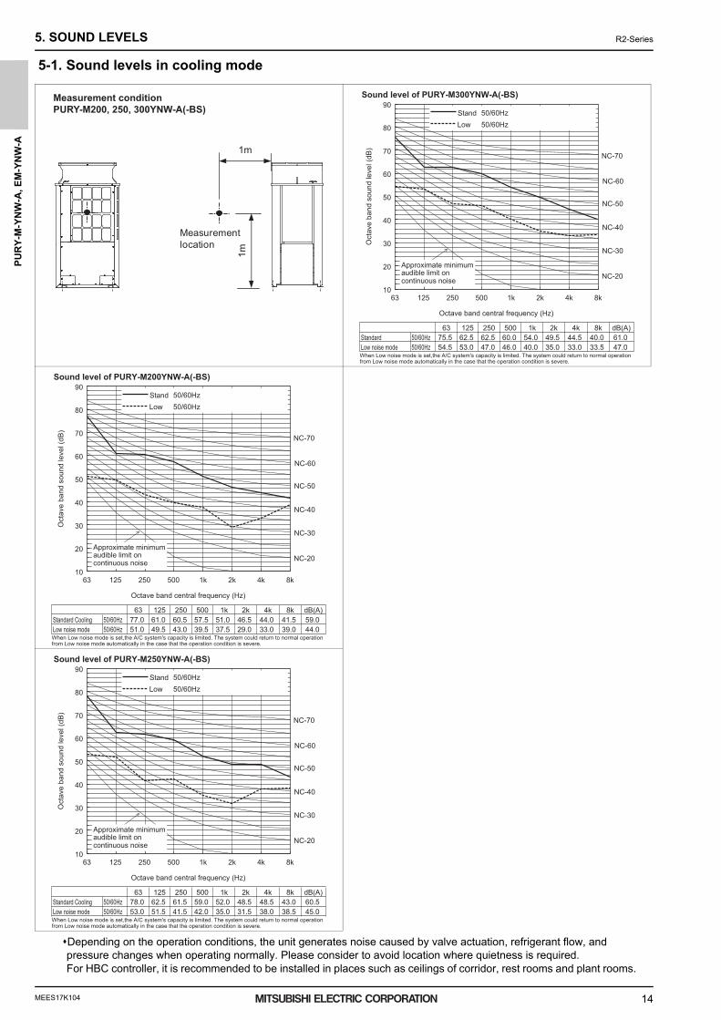
5. SOUND LEVELS5-1. Sound levels in cooling mode
Depending on the operation conditions, the unit generates noise caused by valve actuation, refrigerant flow, and pressure changes when operating normally. Please consider to avoid location where quietness is required.For HBC controller, it is recommended to be installed in places such as ceilings of corridor, rest rooms and plant rooms.
Measurementlocation
1m
1m
Measurement conditionPURY-M200, 250, 300YNW-A(-BS)
63 125 250 500 1k 2k 4k 8k dB(A)Standard 50/60Hz 75.5 62.5 62.5 60.0 54.0 49.5 44.5 40.0 61.0Low noise mode 50/60Hz 54.5 53.0 47.0 46.0 40.0 35.0 33.0 33.5 47.0When Low noise mode is set,the A/C system's capacity is limited. The system could return to normal operationfrom Low noise mode automatically in the case that the operation condition is severe.
10
20
30
40
50
60
70
80
90
63 125 250 500 1k 2k 4k 8k
NC-40
NC-30
NC-20
NC-60
NC-50
NC-70
Octave band central frequency (Hz)
Oct
ave
band
sou
nd le
vel (
dB)
Approximate minimumaudible limit oncontinuous noise
Stand 50/60HzLow 50/60Hz
Sound level of PURY-M300YNW-A(-BS)
63 125 250 500 1k 2k 4k 8k dB(A)Standard Cooling 50/60Hz 77.0 61.0 60.5 57.5 51.0 46.5 44.0 41.5 59.0Low noise mode 50/60Hz 51.0 49.5 43.0 39.5 37.5 29.0 33.0 39.0 44.0When Low noise mode is set,the A/C system's capacity is limited. The system could return to normal operationfrom Low noise mode automatically in the case that the operation condition is severe.
10
20
30
40
50
60
70
80
90
63 125 250 500 1k 2k 4k 8k
NC-40
NC-30
NC-20
NC-60
NC-50
NC-70
Octave band central frequency (Hz)
Oct
ave
band
sou
nd le
vel (
dB)
Approximate minimumaudible limit oncontinuous noise
Stand 50/60HzLow 50/60Hz
Sound level of PURY-M200YNW-A(-BS)
63 125 250 500 1k 2k 4k 8k dB(A)Standard Cooling 50/60Hz 78.0 62.5 61.5 59.0 52.0 48.5 48.5 43.0 60.5Low noise mode 50/60Hz 53.0 51.5 41.5 42.0 35.0 31.5 38.0 38.5 45.0When Low noise mode is set,the A/C system's capacity is limited. The system could return to normal operationfrom Low noise mode automatically in the case that the operation condition is severe.
10
20
30
40
50
60
70
80
90
63 125 250 500 1k 2k 4k 8k
NC-40
NC-30
NC-20
NC-60
NC-50
NC-70
Octave band central frequency (Hz)
Oct
ave
band
sou
nd le
vel (
dB)
Approximate minimumaudible limit oncontinuous noise
Stand 50/60HzLow 50/60Hz
Sound level of PURY-M250YNW-A(-BS)
0000004760.BOOK 14 ページ 2018年4月26日 木曜日 午後4時31分

MEES17K104
PU
RY
-M-Y
NW
-A, E
M-Y
NW
-A
15
5. SOUND LEVELS R2-Series
Depending on the operation conditions, the unit generates noise caused by valve actuation, refrigerant flow, and pressure changes when operating normally. Please consider to avoid location where quietness is required.For HBC controller, it is recommended to be installed in places such as ceilings of corridor, rest rooms and plant rooms.
Measurementlocation
1m
1m
Measurement conditionPURY-EM200, 250, 300YNW-A(-BS)
63 125 250 500 1k 2k 4k 8k dB(A)Standard Cooling 50/60Hz 75.5 62.5 62.5 60.0 54.0 49.5 44.5 40.0 61.0Low noise mode 50/60Hz 54.5 53.0 47.0 46.0 40.0 35.0 33.0 33.5 47.0When Low noise mode is set,the A/C system's capacity is limited. The system could return to normal operationfrom Low noise mode automatically in the case that the operation condition is severe.
10
20
30
40
50
60
70
80
90
63 125 250 500 1k 2k 4k 8k
NC-40
NC-30
NC-20
NC-60
NC-50
NC-70
Octave band central frequency (Hz)
Oct
ave
band
sou
nd le
vel (
dB)
Approximate minimumaudible limit oncontinuous noise
Stand 50/60HzLow 50/60Hz
Sound level of PURY-EM300YNW-A(-BS)
63 125 250 500 1k 2k 4k 8k dB(A)Standard 50/60Hz 77.0 61.0 60.5 57.5 51.0 46.5 44.0 41.5 59.0Low noise mode 50/60Hz 51.0 49.5 43.0 39.5 37.5 29.0 33.0 39.0 44.0When Low noise mode is set,the A/C system's capacity is limited. The system could return to normal operationfrom Low noise mode automatically in the case that the operation condition is severe.
10
20
30
40
50
60
70
80
90
63 125 250 500 1k 2k 4k 8k
NC-40
NC-30
NC-20
NC-60
NC-50
NC-70
Octave band central frequency (Hz)
Oct
ave
band
sou
nd le
vel (
dB)
Approximate minimumaudible limit oncontinuous noise
Stand 50/60HzLow 50/60Hz
Sound level of PURY-EM200YNW-A(-BS)
63 125 250 500 1k 2k 4k 8k dB(A)Standard 50/60Hz 78.0 62.5 61.5 59.0 52.0 48.5 48.5 43.0 60.5Low noise mode 50/60Hz 53.0 51.5 41.5 42.0 35.0 31.5 38.0 38.5 45.0When Low noise mode is set,the A/C system's capacity is limited. The system could return to normal operationfrom Low noise mode automatically in the case that the operation condition is severe.
10
20
30
40
50
60
70
80
90
63 125 250 500 1k 2k 4k 8k
NC-40
NC-30
NC-20
NC-60
NC-50
NC-70
Octave band central frequency (Hz)
Oct
ave
band
sou
nd le
vel (
dB)
Approximate minimumaudible limit oncontinuous noise
Stand 50/60HzLow 50/60Hz
Sound level of PURY-EM250YNW-A(-BS)
0000004760.BOOK 15 ページ 2018年4月26日 木曜日 午後4時31分

MEES17K104
PU
RY
-M-Y
NW
-A, E
M-Y
NW
-A
16
5. SOUND LEVELS R2-Series
5-2. Sound levels in heating mode
Depending on the operation conditions, the unit generates noise caused by valve actuation, refrigerant flow, and pressure changes when operating normally. Please consider to avoid location where quietness is required.For HBC controller, it is recommended to be installed in places such as ceilings of corridor, rest rooms and plant rooms.
Measurementlocation
1m
1m
Measurement conditionPURY-M200, 250, 300YNW-A(-BS)
63 125 250 500 1k 2k 4k 8k dB(A)Standard Heating 50/60Hz 74.5 70.0 68.5 65.5 60.5 56.5 52.0 48.0 67.0Low noise mode 50/60Hz 60.5 58.0 50.0 47.5 43.0 39.5 38.5 41.5 50.5When Low noise mode is set,the A/C system's capacity is limited. The system could return to normal operationfrom Low noise mode automatically in the case that the operation condition is severe.
10
20
30
40
50
60
70
80
90
63 125 250 500 1k 2k 4k 8k
NC-40
NC-30
NC-20
NC-60
NC-50
NC-70
Octave band central frequency (Hz)
Oct
ave
band
sou
nd le
vel (
dB)
Approximate minimumaudible limit oncontinuous noise
Stand 50/60HzLow 50/60Hz
Sound level of PURY-M300YNW-A(-BS)
63 125 250 500 1k 2k 4k 8k dB(A)Standard Heating 50/60Hz 69.0 61.0 60.5 58.0 52.0 47.5 48.0 42.5 59.0Low noise mode 50/60Hz 43.0 49.0 42.0 40.0 36.0 33.5 37.0 35.5 44.0When Low noise mode is set,the A/C system's capacity is limited. The system could return to normal operationfrom Low noise mode automatically in the case that the operation condition is severe.
10
20
30
40
50
60
70
80
90
63 125 250 500 1k 2k 4k 8k
NC-40
NC-30
NC-20
NC-60
NC-50
NC-70
Octave band central frequency (Hz)
Oct
ave
band
sou
nd le
vel (
dB)
Approximate minimumaudible limit oncontinuous noise
Stand 50/60HzLow 50/60Hz
Sound level of PURY-M200YNW-A(-BS)
63 125 250 500 1k 2k 4k 8k dB(A)Standard Heating 50/60Hz 69.0 62.5 62.0 60.0 54.0 49.5 50.5 44.0 61.0Low noise mode 50/60Hz 47.5 51.5 46.0 44.5 40.5 37.0 41.0 37.5 48.0When Low noise mode is set,the A/C system's capacity is limited. The system could return to normal operationfrom Low noise mode automatically in the case that the operation condition is severe.
10
20
30
40
50
60
70
80
90
63 125 250 500 1k 2k 4k 8k
NC-40
NC-30
NC-20
NC-60
NC-50
NC-70
Octave band central frequency (Hz)
Oct
ave
band
sou
nd le
vel (
dB)
Approximate minimumaudible limit oncontinuous noise
Stand 50/60HzLow 50/60Hz
Sound level of PURY-M250YNW-A(-BS)
0000004760.BOOK 16 ページ 2018年4月26日 木曜日 午後4時31分

MEES17K104
PU
RY
-M-Y
NW
-A, E
M-Y
NW
-A
17
5. SOUND LEVELS R2-Series
Depending on the operation conditions, the unit generates noise caused by valve actuation, refrigerant flow, and pressure changes when operating normally. Please consider to avoid location where quietness is required.For HBC controller, it is recommended to be installed in places such as ceilings of corridor, rest rooms and plant rooms.
Measurementlocation
1m
1m
Measurement conditionPURY-EM200, 250, 300YNW-A(-BS)
63 125 250 500 1k 2k 4k 8k dB(A)Standard Heating 50/60Hz 74.5 70.0 68.5 65.5 60.5 56.5 52.0 48.0 67.0Low noise mode 50/60Hz 60.5 58.0 50.0 47.5 43.0 39.5 38.5 41.5 50.5When Low noise mode is set,the A/C system's capacity is limited. The system could return to normal operationfrom Low noise mode automatically in the case that the operation condition is severe.
10
20
30
40
50
60
70
80
90
63 125 250 500 1k 2k 4k 8k
NC-40
NC-30
NC-20
NC-60
NC-50
NC-70
Octave band central frequency (Hz)
Oct
ave
band
sou
nd le
vel (
dB)
Approximate minimumaudible limit oncontinuous noise
Stand 50/60HzLow 50/60Hz
Sound level of PURY-EM300YNW-A(-BS)
63 125 250 500 1k 2k 4k 8k dB(A)Standard Heating 50/60Hz 69.0 61.0 60.5 58.0 52.0 47.5 48.0 42.5 59.0Low noise mode 50/60Hz 43.0 49.0 42.0 40.0 36.0 33.5 37.0 35.5 44.0When Low noise mode is set,the A/C system's capacity is limited. The system could return to normal operationfrom Low noise mode automatically in the case that the operation condition is severe.
10
20
30
40
50
60
70
80
90
63 125 250 500 1k 2k 4k 8k
NC-40
NC-30
NC-20
NC-60
NC-50
NC-70
Octave band central frequency (Hz)
Oct
ave
band
sou
nd le
vel (
dB)
Approximate minimumaudible limit oncontinuous noise
Stand 50/60HzLow 50/60Hz
Sound level of PURY-EM200YNW-A(-BS)
63 125 250 500 1k 2k 4k 8k dB(A)Standard Heating 50/60Hz 69.0 62.5 62.0 60.0 54.0 49.5 50.5 44.0 61.0Low noise mode 50/60Hz 47.5 51.5 46.0 44.5 40.5 37.0 41.0 37.5 48.0When Low noise mode is set,the A/C system's capacity is limited. The system could return to normal operationfrom Low noise mode automatically in the case that the operation condition is severe.
10
20
30
40
50
60
70
80
90
63 125 250 500 1k 2k 4k 8k
NC-40
NC-30
NC-20
NC-60
NC-50
NC-70
Octave band central frequency (Hz)
Oct
ave
band
sou
nd le
vel (
dB)
Approximate minimumaudible limit oncontinuous noise
Stand 50/60HzLow 50/60Hz
Sound level of PURY-EM250YNW-A(-BS)
0000004760.BOOK 17 ページ 2018年4月26日 木曜日 午後4時31分

MEES17K104
PU
RY
-M-Y
NW
-A, E
M-Y
NW
-A
18
6. VIBRATION LEVEL R2-Series
6. VIBRATION LEVEL[PURY-M200-300YNW, PURY-EM200-300YNW]
* Vibration level varies depending on the conditions of actual installation site.
20cm10cm
Concrete
Service panel side
Measurement point
Measurement condition
Measurement frequency: 1 Hz-80 Hz
Measurement point: Ground surface 20 cm away from the unit leg
Installation condition: Direct installation on the concrete floor
Power source: 3-phase 4-wire 380-400-415 V 50/60 Hz
Operation condition: JIS condition (cooling, heating)
Measurement device: Vibration level meter for vibration pollution VM-1220C (JIS-compliant product)
Vibration level
Model Vibration level (dB)
PURY-M200YNW-A (-BS) 45
PURY-M250YNW-A (-BS) 46
PURY-M300YNW-A (-BS) 47
PURY-EM200YNW-A (-BS) 45
PURY-EM250YNW-A (-BS) 46
PURY-EM300YNW-A (-BS) 47
0000004760.BOOK 18 ページ 2018年4月26日 木曜日 午後4時31分

MEES17K104
PU
RY
-M-Y
NW
-A, E
M-Y
NW
-A
19
7. OPERATION TEMPERATURE RANGE R2-Series
7. OPERATION TEMPERATURE RANGE
Outdoor temperature
15 to 24 CWB (59 to 75 FWB)
15 to 27 CDB (59 to 81 FDB)
Indoor temperature
Cooling Heating
-11 to 15.5 CWB (12.2 to 60 FWB)
-10 to 21 CDB (14 to 70 FDB)
Combination of cooling/heating operation (Cooling main or Heating main)
40
25
20
15
10
0
35
30
5
-20 -15 -10 -5 0 5 10 15 20 25 30 35 40 45 50
Indo
or te
mpe
ratu
re
Outdoor temperature
Range for continuous operation
Continuous operation not recommended
Continuous operation not recommended
Cooling only
Heating only
Indo
or te
mpe
ratu
re
30
25
20
15
5
0-20 -15 -10 -5 0 5 10 15 20 25 30 35 40 45 60-4 5 14 23 32 41 50 59 68 77 86 95 104 113 140
50122
Outdoor temperature
86
77
68
59
41
32
1050
104
95
86
77
59
50
41
32
68
Range for continuous operation
Continuous operation not recommended
-4 5 14 23 32 41 50 59 68 77 86 95 104 113 122
0000004760.BOOK 19 ページ 2018年4月26日 木曜日 午後4時31分

MEES17K104
PU
RY
-M-Y
NW
-A, E
M-Y
NW
-A
20
8. CAPACITY TABLES R2-Series
8. CAPACITY TABLES8-1. Correction by temperatureHYBRID CITY MULTI could have varied capacity at different designing temperature. Using the nominal cooling/heating capacity value and the ratio below, the capacity can be observed at various temperature.
M200YNW-A22.4
76,4006.85
M250YNW-A28.0
95,5009.92
PURY-
EM200YNW-A22.4
76,4006.15
EM250YNW-A28.0
95,5008.77
PURY-
Indoor unit temperature correctionNominalCoolingCapacityInput
kWBTU/hkW
NominalCoolingCapacityInput
kWBTU/hkW
Indoor Temperature [°CW.B.]
Rat
io o
f coo
ling
capa
city
To be used to correct indoor unit capacity only
15 16 17 18 19 20 21 22 23 240.8
0.9
1.0
1.1
1.2
Outdoor unit temperature correctionTo be used to correct outdoor unit onlyOutdoor unit capacity is NOT affected by the indoor temperature.Outdoor unit power input is affected by the indoor and outdoor temperatures. Please consult the sales office for details.
1.1
0.9
0.8
0.7
0.6
0.5
0.4
0.3
1.0
1.2
Rat
io o
f coo
ling
capa
city
°CD.B.°FD.B.
0.8
0.9
1.0
1.2
1.1
1.3
0.7
0.6
0.5
0.0
0.3
0.2
0.1
0.4
Rat
io o
f pow
er in
put
-523
032
541
1050
1559
2068
2577
3086
3595
40104
45113
50122
-523
032
541
1050
1559
2068
2577
3086
3595
40104
45113
50122
°CD.B.°FD.B.
Indoor Temperature
Outdoor Temperature
Outdoor Temperature
24°CW.B.75°FW.B.
22°CW.B.72°FW.B.
20°CW.B.68°FW.B.
18°CW.B.64°FW.B.
19°CW.B.66°FW.B.
16°CW.B.61°FW.B.
15°CW.B.59°FW.B.
0000004760.BOOK 20 ページ 2018年4月26日 木曜日 午後4時31分

MEES17K104
PU
RY
-M-Y
NW
-A, E
M-Y
NW
-A
21
8. CAPACITY TABLES R2-Series
M200YNW-A25.0
85,3006.94
M250YNW-A31.5
107,50010.06
PURY- Indoor unit temperature correctionNominalHeatingCapacityInput
kWBTU/hkW
To be used to correct indoor unit capacity only
Indoor Temperature [°CD.B.]
Rat
io o
f hea
ting
capa
city
15 16 17 18 19 20 21 22 23 272625240.6
0.7
0.8
0.9
1.0
1.1
1.1
0.9
0.8
0.7
0.6
0.5
1.0
1.2
Rat
io o
f hea
ting
capa
city
0.9
1.0
1.1
1.3
1.2
1.4
0.8
0.7
0.6
0.4
0.5
Rat
io o
f pow
er in
put
-20-4
-155
-1014
-523
032
541
1050
1559
°CW.B.°FW.B.
Indoor Temperature
Outdoor Temperature
-20-4
-155
-1014
-523
032
541
1050
1559
°CW.B.°FW.B.
Outdoor Temperature
27°CD.B.81°FD.B.
25°CD.B.77°FD.B.
20°CD.B.68°FD.B.
15°CD.B.59°FD.B.
EM200YNW-A25.0
85,3006.77
EM250YNW-A31.5
107,5009.84
PURY-NominalHeatingCapacityInput
kWBTU/hkW
Outdoor unit temperature correctionTo be used to correct outdoor unit onlyOutdoor unit capacity is NOT affected by the indoor temperature.Outdoor unit power input is affected by the indoor and outdoor temperatures. Please consult the sales office for details.
0000004760.BOOK 21 ページ 2018年4月26日 木曜日 午後4時31分

MEES17K104
PU
RY
-M-Y
NW
-A, E
M-Y
NW
-A
22
8. CAPACITY TABLES R2-Series
M300YNW-A33.5
114,30011.09
PURY-
EM300YNW-A33.5
114,30010.02
Indoor unit temperature correction
1.1
0.9
0.8
0.7
0.6
0.5
0.4
0.3
1.0
1.2
Rat
io o
f coo
ling
capa
city
°CD.B.°FD.B.
0.8
0.9
1.0
1.2
1.1
1.3
0.7
0.6
0.5
0.0
0.3
0.2
0.1
0.4
Rat
io o
f pow
er in
put
-523
032
541
1050
1559
2068
2577
3086
3595
40104
45113
50122
-523
032
541
1050
1559
2068
2577
3086
3595
40104
45113
50122
°CD.B.°FD.B.
Indoor Temperature
Outdoor Temperature
Outdoor Temperature
24°CW.B.75°FW.B.
22°CW.B.72°FW.B.
20°CW.B.68°FW.B.
Indoor Temperature [°CW.B.]
Rat
io o
f coo
ling
capa
city
To be used to correct indoor unit capacity only
15 16 17 18 19 20 21 22 23 240.8
0.9
1.0
1.1
1.2
18°CW.B.64°FW.B.
19°CW.B.66°FW.B.
16°CW.B.61°FW.B.
15°CW.B.59°FW.B.
Outdoor unit temperature correctionTo be used to correct outdoor unit onlyOutdoor unit capacity is NOT affected by the indoor temperature.Outdoor unit power input is affected by the indoor and outdoor temperatures. Please consult the sales office for details.
PURY-
NominalCoolingCapacityInput
kWBTU/hkW
NominalCoolingCapacityInput
kWBTU/hkW
0000004760.BOOK 22 ページ 2018年4月26日 木曜日 午後4時31分

MEES17K104
PU
RY
-M-Y
NW
-A, E
M-Y
NW
-A
23
8. CAPACITY TABLES R2-Series
Indoor unit temperature correctionTo be used to correct indoor unit capacity only
Indoor Temperature [°CD.B.]
Rat
io o
f hea
ting
capa
city
15 16 17 18 19 20 21 22 23 272625240.6
0.7
0.8
0.9
1.0
1.1
1.1
0.9
0.8
0.7
0.6
0.5
1.0
1.2
Rat
io o
f hea
ting
capa
city
0.9
1.0
1.1
1.3
1.2
1.4
0.8
0.7
0.6
0.4
0.5
Rat
io o
f pow
er in
put
-20-4
-155
-1014
-523
032
541
1050
1559
°CW.B.°FW.B.
Indoor Temperature
Outdoor Temperature
-20-4
-155
-1014
-523
032
541
1050
1559
°CW.B.°FW.B.
Outdoor Temperature
27°CD.B.81°FD.B.
25°CD.B.77°FD.B.
20°CD.B.68°FD.B.
15°CD.B.59°FD.B.
M300YNW-A37.5
128,00011.68
PURY-NominalHeatingCapacityInput
kWBTU/hkW
EM300YNW-A37.5
128,00010.90
PURY-NominalHeatingCapacityInput
kWBTU/hkW
Outdoor unit temperature correctionTo be used to correct outdoor unit onlyOutdoor unit capacity is NOT affected by the indoor temperature.Outdoor unit power input is affected by the indoor and outdoor temperatures. Please consult the sales office for details.
0000004760.BOOK 23 ページ 2018年4月26日 木曜日 午後4時31分

MEES17K104
PU
RY
-M-Y
NW
-A, E
M-Y
NW
-A
24
8. CAPACITY TABLES R2-Series
Correction by temperature (COP Priority Mode)HYBRID CITY MULTI could have various capacities at different designing temperatures. Using the nominal cooling/heating capacity values and the ratios below, the capacity can be found for various temperatures.To select COP priority mode, SW4 (935) must be set to ON.
M200YNW-A22.4
76,4006.85
M250YNW-A28.0
95,5009.92
PURY-
EM200YNW-A22.4
76,4006.15
EM250YNW-A28.0
95,5008.77
PURY-
Indoor unit temperature correctionNominalCoolingCapacityInput
kWBTU/hkW
NominalCoolingCapacityInput
kWBTU/hkW
Indoor Temperature [°CW.B.]R
atio
of c
oolin
g ca
paci
ty
To be used to correct indoor unit capacity only
15 16 17 18 19 20 21 22 23 240.8
0.9
1.0
1.1
1.2
Outdoor unit temperature correctionTo be used to correct outdoor unit onlyOutdoor unit capacity is NOT affected by the indoor temperature.Outdoor unit power input is affected by the indoor and outdoor temperatures. Please consult the sales office for details.
1.1
0.9
0.8
0.7
0.6
0.5
0.4
0.3
1.0
1.2
Rat
io o
f coo
ling
capa
city
°CD.B.°FD.B.
0.8
0.9
1.0
1.2
1.1
1.3
0.7
0.6
0.5
0.0
0.3
0.2
0.1
0.4
Rat
io o
f pow
er in
put
-523
032
541
1050
1559
2068
2577
3086
3595
40104
45113
50122
-523
032
541
1050
1559
2068
2577
3086
3595
40104
45113
50122
°CD.B.°FD.B.
Indoor Temperature
Outdoor Temperature
Outdoor Temperature
24°CW.B.75°FW.B.
22°CW.B.72°FW.B.
20°CW.B.68°FW.B.
18°CW.B.64°FW.B.
19°CW.B.66°FW.B.
16°CW.B.61°FW.B.
15°CW.B.59°FW.B.
0000004760.BOOK 24 ページ 2018年4月26日 木曜日 午後4時31分
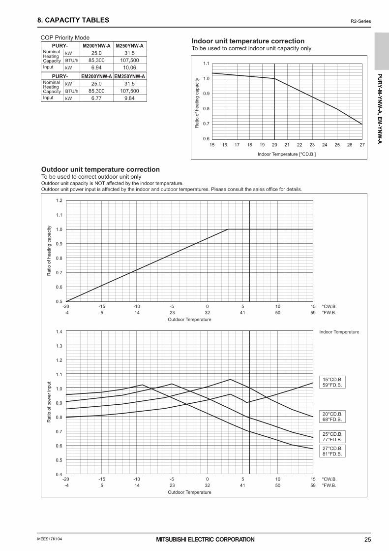
MEES17K104
PU
RY
-M-Y
NW
-A, E
M-Y
NW
-A
25
8. CAPACITY TABLES R2-Series
M200YNW-A25.0
85,3006.94
M250YNW-A31.5
107,50010.06
PURY-Indoor unit temperature correction
NominalHeatingCapacityInput
kWBTU/hkW
To be used to correct indoor unit capacity only
1.1
0.9
0.8
0.7
0.6
0.5
1.0
1.2
Rat
io o
f hea
ting
capa
city
0.9
1.0
1.1
1.3
1.2
1.4
0.8
0.7
0.6
0.4
0.5
Rat
io o
f pow
er in
put
-20-4
-155
-1014
-523
032
541
1050
1559
°CW.B.°FW.B.
Indoor Temperature
Outdoor Temperature
-20-4
-155
-1014
-523
032
541
1050
1559
°CW.B.°FW.B.
Outdoor Temperature
27°CD.B.81°FD.B.
25°CD.B.77°FD.B.
20°CD.B.68°FD.B.
15°CD.B.59°FD.B.
EM200YNW-A25.0
85,3006.77
EM250YNW-A31.5
107,5009.84
PURY-NominalHeatingCapacityInput
kWBTU/hkW
Outdoor unit temperature correctionTo be used to correct outdoor unit onlyOutdoor unit capacity is NOT affected by the indoor temperature.Outdoor unit power input is affected by the indoor and outdoor temperatures. Please consult the sales office for details.
COP Priority Mode
Indoor Temperature [°CD.B.]
Rat
io o
f hea
ting
capa
city
15 16 17 18 19 20 21 22 23 272625240.6
0.7
0.8
0.9
1.0
1.1
0000004760.BOOK 25 ページ 2018年4月26日 木曜日 午後4時31分

MEES17K104
PU
RY
-M-Y
NW
-A, E
M-Y
NW
-A
26
8. CAPACITY TABLES R2-Series
M300YNW-A33.5
114,30013.08
PURY-
EM300YNW-A33.5
114,30011.79
Indoor unit temperature correction
1.1
0.9
0.8
0.7
0.6
0.5
0.4
0.3
1.0
1.2
Rat
io o
f coo
ling
capa
city
°CD.B.°FD.B.
0.8
0.9
1.0
1.2
1.1
1.3
0.7
0.6
0.5
0.0
0.3
0.2
0.1
0.4
Rat
io o
f pow
er in
put
-523
032
541
1050
1559
2068
2577
3086
3595
40104
45113
50122
-523
032
541
1050
1559
2068
2577
3086
3595
40104
45113
50122
°CD.B.°FD.B.
Indoor Temperature
Outdoor Temperature
Outdoor Temperature
24°CW.B.75°FW.B.
22°CW.B.72°FW.B.
20°CW.B.68°FW.B.
Indoor Temperature [°CW.B.]
Rat
io o
f coo
ling
capa
city
To be used to correct indoor unit capacity only
15 16 17 18 19 20 21 22 23 240.8
0.9
1.0
1.1
1.2
18°CW.B.64°FW.B.
19°CW.B.66°FW.B.
16°CW.B.61°FW.B.
15°CW.B.59°FW.B.
Outdoor unit temperature correctionTo be used to correct outdoor unit onlyOutdoor unit capacity is NOT affected by the indoor temperature.Outdoor unit power input is affected by the indoor and outdoor temperatures. Please consult the sales office for details.
PURY-
NominalCoolingCapacityInput
kWBTU/hkW
NominalCoolingCapacityInput
kWBTU/hkW
0000004760.BOOK 26 ページ 2018年4月26日 木曜日 午後4時31分

MEES17K104
PU
RY
-M-Y
NW
-A, E
M-Y
NW
-A
27
8. CAPACITY TABLES R2-Series
Indoor unit temperature correctionTo be used to correct indoor unit capacity only
1.1
0.9
0.8
0.7
0.6
0.5
1.0
1.2
Rat
io o
f hea
ting
capa
city
0.9
1.0
1.1
1.3
1.2
1.4
0.8
0.7
0.6
0.4
0.5
Rat
io o
f pow
er in
put
-20-4
-155
-1014
-523
032
541
1050
1559
°CW.B.°FW.B.
Indoor Temperature
Outdoor Temperature
-20-4
-155
-1014
-523
032
541
1050
1559
°CW.B.°FW.B.
Outdoor Temperature
27°CD.B.81°FD.B.
25°CD.B.77°FD.B.
20°CD.B.68°FD.B.
15°CD.B.59°FD.B.
M300YNW-A37.5
128,00011.68
PURY-NominalHeatingCapacityInput
kWBTU/hkW
EM300YNW-A37.5
128,00010.90
PURY-NominalHeatingCapacityInput
kWBTU/hkW
Outdoor unit temperature correctionTo be used to correct outdoor unit onlyOutdoor unit capacity is NOT affected by the indoor temperature.Outdoor unit power input is affected by the indoor and outdoor temperatures. Please consult the sales office for details.
COP Priority Mode
Indoor Temperature [°CD.B.]
Rat
io o
f hea
ting
capa
city
15 16 17 18 19 20 21 22 23 272625240.6
0.7
0.8
0.9
1.0
1.1
0000004760.BOOK 27 ページ 2018年4月26日 木曜日 午後4時31分

MEES17K104
PU
RY
-M-Y
NW
-A, E
M-Y
NW
-A
28
8. CAPACITY TABLES R2-Series
8-2. Correction by total indoorHYBRID CITY MULTI system has different capacities and inputs when many combinations of indoor units with different total ca-pacities are connected. Using following tables, the maximum capacity can be found to ensure the system is installed with enough capacity for a particular application.
Total capacity of indoor units
Rat
io o
f cap
acity
Rat
io o
f pow
er in
put
Total capacity of indoor units
Rat
io o
f cap
acity
Rat
io o
f pow
er in
put
PURY-(E)M250YNW-A
PURY-(E)M200YNW-A
CoolingHeating
50 100 200 300150 250 350
0.2
1.2
1.0
0.8
0.6
0.4
1.0
0.8
0.6
0.4
0.2
1.2
CoolingHeating
100 150 250 350200 300 400
0.2
1.2
1.0
0.8
0.6
0.4
1.0
0.8
0.6
0.4
0.2
1.2
NominalCoolingCapacityInput
kWBTU/hkW
PURY-M250YNW-A28.0
95,5009.92
NominalHeatingCapacityInput
kWBTU/hkW
PURY-M250YNW-A31.5
107,50010.06
NominalCoolingCapacityInput
kWBTU/hkW
PURY-M200YNW-A22.4
76,4006.85
NominalHeatingCapacityInput
kWBTU/hkW
PURY-M200YNW-A25.0
85,3006.94
NominalCoolingCapacityInput
kWBTU/hkW
PURY-EM250YNW-A28.0
95,5008.77
NominalHeatingCapacityInput
kWBTU/hkW
PURY-EM250YNW-A31.5
107,5009.84
NominalCoolingCapacityInput
kWBTU/hkW
PURY-EM200YNW-A22.4
76,4006.15
NominalHeatingCapacityInput
kWBTU/hkW
PURY-EM200YNW-A25.0
85,3006.77
0000004760.BOOK 28 ページ 2018年4月26日 木曜日 午後4時31分

MEES17K104
PU
RY
-M-Y
NW
-A, E
M-Y
NW
-A
29
8. CAPACITY TABLES R2-Series
Total capacity of indoor units100 200 300 400 500
Rat
io o
f cap
acity
Rat
io o
f pow
er in
put
0.2
1.2
1.0
0.8
0.6
0.4
1.0
0.8
0.6
0.4
0.2
1.2
PURY-(E)M300YNW-A
CoolingHeating
NominalCoolingCapacityInput
kWBTU/hkW
PURY-M300YNW-A33.5
114,30011.09
NominalHeatingCapacityInput
kWBTU/hkW
PURY-M300YNW-A37.5
128,00011.68
NominalCoolingCapacityInput
kWBTU/hkW
PURY-EM300YNW-A33.5
114,30010.02
NominalHeatingCapacityInput
kWBTU/hkW
PURY-EM300YNW-A37.5
128,00010.90
0000004760.BOOK 29 ページ 2018年4月26日 木曜日 午後4時31分

MEES17K104
PU
RY
-M-Y
NW
-A, E
M-Y
NW
-A
30
8. CAPACITY TABLES R2-Series
8-3. Correction by piping lengthA decrease in cooling/heating capacity will occur due to piping length increase. Using the following correction factors according to the equivalent length of the piping shown at 8-3-1 and 8-3-2 the capacity can be calculated. 8-3-3 shows how to obtain the equiv-alent length of piping. Refrigerant piping and water piping have separate correction factors.
8-3-1. Cooling capacity correction
HBC to outdoor unit refrigerant piping equivalent length (m)
1
0.90
0.80
0.95
0.85
0.75
0.65
0.70
Coo
ling
capa
city
cor
rect
ion
fact
or
PURY-(E)M200YNW-A(-BS) Total capacity of indoor unit100
150
200300
0 20 40 60 80 100 120 140 160 180
PURY-(E)M200YNW-A(-BS)
Water piping equivalent length to farthest indoor unit (m)
Coo
ling
capa
city
cor
rect
ion
fact
or
1
0.98
0.96
0.99
0.97
0.95
0.93
0.92
0.91
0.94
0 10 20 30 40 50 60 70
HBC to outdoor unit refrigerant piping equivalent length (m)
1
0.90
0.80
0.95
0.85
0.75
0.65
0.70
Coo
ling
capa
city
cor
rect
ion
fact
or
PURY-(E)M250YNW-A(-BS) Total capacity of indoor unit125
188
250375
0 20 40 60 80 100 120 140 160 180
PURY-(E)M250YNW-A(-BS)
Water piping equivalent length to farthest indoor unit (m)
Coo
ling
capa
city
cor
rect
ion
fact
or
1
0.98
0.96
0.99
0.97
0.95
0.93
0.92
0.91
0.94
0 10 20 30 40 50 60 70
HBC to outdoor unit refrigerant piping equivalent length (m)
1
0.90
0.80
0.95
0.85
0.75
0.65
0.70
Co
olin
g c
ap
aci
ty c
orr
ect
ion
fa
cto
r
PURY-(E)M300YNW-A(-BS) Total capacity of indoor unit150
225
300
4500 20 40 60 80 100 120 140 160 180
PURY-(E)M300YNW-A(-BS)
Water piping equivalent length to farthest indoor unit (m)
Coo
ling
capa
city
cor
rect
ion
fact
or
1
0.98
0.96
0.99
0.97
0.95
0.93
0.92
0.91
0.94
0 10 20 30 40 50 60 70
0000004760.BOOK 30 ページ 2018年4月26日 木曜日 午後4時31分

MEES17K104
PU
RY
-M-Y
NW
-A, E
M-Y
NW
-A
31
8. CAPACITY TABLES R2-Series
8-3-2. Heating capacity correction
8-3-3. How to obtain the equivalent piping lengthRefrigerant pipe1. PURY-(E)M200, 250, 300YNW(-BS)
Equivalent length = (Actual piping length to the farthest indoor unit) + (0.35 × number of bends in the piping) [m]
Water pipeEquivalent length = (Actual piping length to the farthest indoor unit) + (0.55 × number of bends in the piping) [m]
8-4. Correction at frost and defrostDue to frost at the outdoor heat exchanger and the automatic defrost operation, the heating capacity of the outdoor unit can be calculated by multiplying the correction factor shown in the table below.
Table of correction factor at frost and defrost
0.800 20 40 60 80 100 120 140 160
Hea
ting
capa
city
cor
rect
ion
fact
or
0.90
1.00
HBC to outdoor unit refrigerant piping equivalent length (m)
PURY-(E)M200YNW-A(-BS) PURY-(E)M200YNW-A(-BS)
Water piping equivalent length to farthest indoor unit (m)
Hea
ting
capa
city
cor
rect
ion
fact
or
1
0.98
0.96
0.99
0.97
0.95
0.93
0.92
0.91
0.94
0 10 20 30 40 50 60 70
0.800 20 40 60 80 100 120 140 160
Hea
ting
capa
city
cor
rect
ion
fact
or
0.90
1.00
HBC to outdoor unit refrigerant piping equivalent length (m)
PURY-(E)M250, 300YNW-A(-BS) PURY-(E)M250, 300YNW-A(-BS)
Water piping equivalent length to farthest indoor unit (m)
Hea
ting
capa
city
cor
rect
ion
fact
or
1
0.98
0.96
0.99
0.97
0.95
0.93
0.92
0.91
0.94
0 10 20 30 40 50 60 70
Outdoor inlet air temp. °CWB 6 4 2 1 0 -2 -4 -6 -8 -10 -20
Outdoor inlet air temp. °FWB 43 39 36 34 32 28 25 21 18 14 -4
PURY-(E)M200YNW-A(-BS) 1.00 0.95 0.84 0.83 0.83 0.87 0.90 0.95 0.95 0.95 0.95
PURY-(E)M250YNW-A(-BS) 1.00 0.95 0.84 0.83 0.83 0.87 0.90 0.95 0.95 0.95 0.95
PURY-(E)M300YNW-A(-BS) 1.00 0.93 0.82 0.80 0.82 0.86 0.90 0.90 0.95 0.95 0.95
0000004760.BOOK 31 ページ 2018年4月26日 木曜日 午後4時31分

MEES17K104
PU
RY
-M-Y
NW
-A, E
M-Y
NW
-A
32
8. CAPACITY TABLES R2-Series
8-5. Correction by antifreeze solution concentrationIn HYBRID CITY MULTI system, antifreeze solution should be used to prevent the system from freezing. Refer to the following graphs for the capacity correction by antifreeze solution. Refer to 8-5-1 for antifreeze solution concentration, 8-5-2 and 8-5-3 for capacity correction by antifreeze solution concentration.
8-5-1. Antifreeze solution concentrationUse propylene glycol solution for antifreeze.Refer to the following graph to estimate the antifreeze solution concentration required for freeze protection.DipSW setting (SW5-4 and 5-5) is required in HBC unit depending on the antifreeze solution concentration.Refer the table A for the setting.
8-5-2. Capacity correction by antifreeze solution concentration (cooling)
8-5-3. Capacity correction by antifreeze solution concentration (heating)
0 10 20 30 40 50 60 70
Free
zing
Tem
pera
ture
[ °C
]
0
-5
-10
-15
-20
-25
-30
Antifreeze solution concentration [wt%]
Table ABrine concentration [%] 0 to 29% 30 to 49% 50 to 59% 60 to 70%
OFF OFF ON ONOFF ON OFF ONOFF OFF 1 1OFF 1 OFF 1
DipSW5-4DipSW5-5
7seg LEDLD2LD3
0 10 20 30 40 50
Rat
io o
f coo
ling
capa
city
10.99
0.98
0.970.96
0.95
0.94
0.93
0.92
0.91
0.9
Antifreeze solution concentration [wt%]0 10 20 30 40 50
Rat
io o
f coo
ling
inpu
t
10.99
0.98
0.970.96
0.95
0.94
0.93
0.92
0.91
0.9
Antifreeze solution concentration [wt%]
0 10 20 30 40 50
Rat
io o
f hea
ting
capa
city
10.99
0.98
0.970.96
0.95
0.94
0.93
0.92
0.91
0.9
Antifreeze solution concentration [wt%]0 10 20 30 40 50
Rat
io o
f hea
ting
inpu
t
1.21.18
1.16
1.141.12
1.1
1.08
1.06
1.04
1.02
1
Antifreeze solution concentration [wt%]
0000004760.BOOK 32 ページ 2018年4月26日 木曜日 午後4時31分

MEES17K104
PU
RY
-M-Y
NW
-A, E
M-Y
NW
-A
33
9. ELECTRICAL WORK R2-Series
9. ELECTRICAL WORK9-1. Power supply for Outdoor unit
9-1-1. Electrical characteristics of the outdoor unit in cooling mode
Symbols: MCA: Max Circuit Amps
RLA: Rated Load Amps SC: Starting Current
PURY-M-YNW-A Unit CombinationUnits
Power supply
Compressor FAN RLA(A)(50/60Hz)
Hz VoltsVoltage range
MCA(A)Output(kW)
SC(A) Output(kW) Cooling Heating
PURY-M200YNW-A(-BS) -50/60
380400415
Max:456VMin:342V
16.1 6.0 8 0.92 11.5/10.9/10.5 11.7/11.1/10.7
PURY-M250YNW-A(-BS) - 20.4 7.5 8 0.92 16.7/15.9/15.3 16.9/16.1/15.5
PURY-M300YNW-A(-BS) - 25.1 8.5 8 0.92 18.7/17.7/17.1 19.7/18.7/18.0
PURY-EM-YNW-A Unit CombinationUnits
Power supply
Compressor FAN RLA(A)(50/60Hz)
Hz VoltsVoltage range
MCA(A)Output
(kW)SC(A) Output(kW) Cooling Heating
PURY-EM200YNW-A(-BS) -50/60
380400415
Max:456VMin:342V
16.1 6.0 8 0.92 10.3/9.8/9.5 11.4/10.8/10.4
PURY-EM250YNW-A(-BS) - 19.8 7.5 8 0.92 14.8/14.0/13.5 16.6/15.7/15.2
PURY-EM300YNW-A(-BS) - 23.4 8.5 8 0.92 16.9/16.0/15.4 18.4/17.4/16.8
0000004760.BOOK 33 ページ 2018年4月26日 木曜日 午後4時31分

MEES17K104
PU
RY
-M-Y
NW
-A, E
M-Y
NW
-A
34
9. ELECTRICAL WORK R2-Series
9-2. Power cable specifications
Thickness of wire for main power supply, capacities of the switch and system impedance
ModelMinimum wire thickness (mm2)
Ground-fault interrupter *1Local switch (A) Breaker for wiring (A)
(Non-fuse breaker)Max. Permissive
System ImpedanceMain cable Branch Ground Capacity Fuse
Outdoor unit PURY-(E)M200YNW-A 4.0 - 4.0 30A 100mA 0.1sec. or less 25 25 30 *2
PURY-(E)M250YNW-A 4.0 - 4.0 30A 100mA 0.1sec. or less 32 32 30 *2
PURY-(E)M300YNW-A 4.0 - 4.0 30A 100mA 0.1sec. or less 32 32 30 *2
Total operating current ofthe indoor unit
F0 = 20A or less *3 1.5 1.5 1.5 Current sensitivity *4 16 16 20 (apply to IEC61000-3-3)
F0 = 30A or less *3 2.5 2.5 2.5 Current sensitivity *4 25 25 30 (apply to IEC61000-3-3)
F0 = 40A or less *3 4.0 4.0 4.0 Current sensitivity *4 32 32 40 (apply to IEC61000-3-3)
*1 The Ground-fault interrupter should support Inverter circuit. The Ground-fault interrupter should combine using of local switch or wiring breaker.
*2 Meet technical requirements of IEC61000-3-3
*3 Please take the larger of F1 or F2 as the value for F0.
F1 = Total operating maximum current of the indoor units × 1.2
F2 = {V1 × (Quantity of Type1)/C} + {V1 × (Quantity of Type2)/C} + {V1 × (Quantity of Type3)/C} + {V1 × (Quantity of Type4)/C}
Indoor unit V1 V2
Type1 PEFY-VMS, PFFY-VLRMM 18.6 2.4
Type2 PEFY-VMA 38 1.6
Type3 PLFY-VBM 19.8 2.4
Type4 PLFY-VFM 17.1 2.4
C: Multiple of tripping current at tripping time 0.01s
Please pick up "C" from the tripping characteristic of the breaker.
<Example of "F2" calculation>
*Condition PEFY-VMS × 4 + PEFY-VMA × 1, C = 8 (refer to right sample chart)
F2 = 18.6 × 4/8 + 38 × 1/8
= 14.05
→16 A breaker (Tripping current = 8 × 16 A at 0.01s)
*4 Current sensitivity is calculated using the following formula.
G1 = (V2 × Quantity of Type1) + (V2 × Quantity of Type2) + (V2 × Quantity of Type3) + (V2 × Quantity of Type4)
G1 Current sensitivity Wire thickness V3
30 or less 30 mA 0.1sec or less 1.5 mm2 48
100 or less 100 mA 0.1sec or less 2.5 mm2 56
4.0 mm2 66
1. Use dedicated power supplies for the outdoor unit and indoor unit. Ensure OC and OS are wired individually.2. Bear in mind ambient conditions (ambient temperature, direct sunlight, rain water, etc.) when proceeding with the wiring and connections.3. The wire size is the minimum value for metal conduit wiring. If the voltage drops, use a wire that is one rank thicker in diameter. Make sure the power-supply voltage does not drop more
than 10%. Make sure that the voltage imbalance between the phases is 2% or less.
4. Specific wiring requirements should adhere to the wiring regulations of the region.5. Power supply cords of parts of appliances for outdoor use shall not be lighter than polychloroprene sheathed flexible cord (design 60245 IEC57). For example, use wiring such as YZW.6. A switch with at least 3 mm contact separation in each pole shall be provided when the Air Conditioner is installed.
20
C
108643210.01
0.1
1
10
60
600
6000
SAMPLE
Trip
ping
Tim
e [s
]
Rated Tripping current (x)Sample chart
Be sure to use specified wires for connections and ensure no external force is imparted to terminal connections. If connections are not fixed firmly, heating or fire may result.
Be sure to use the appropriate type of overcurrent protection switch. Note that generated overcurrent may include some amount of direct current.
The breakers for current leakage should support Inverter circuit. (e.g. Mitsubishi Electric's NV-S-Series or equivalent). If no earth leakage breaker is installed, it may cause an electric shock.
Breakers for current leakage should combine using of switch.
Do not use anything other than a breaker with the correct capacity. Using a breaker of too large capacity may cause malfunction or fire.
If a large electric current flows due to malfunction or faulty wiring, earth-leakage breakers on the unit side and on the upstream side of the power supply system may both operate.Depending on the importance of the system, separate the power supply system or take protective coordination of breakers.
This device is intended for the connection to a power supply system with a maximum permissible system impedance shown in the above table at the interface point (power service box) of the user's supply.
The user must ensure that this device is connected only to a power supply system which fulfils the requirement above.If necessary, the user can ask the public power supply company for the system impedance at the interface point.
This equipment complies with IEC 61000-3-12 provided that the short-circuit power Ssc is greater than or equal to Ssc (*2) at the interface point between the user's supply and the public system. It is the responsibility of the installer or user of the equipment to ensure, by consultation with the distribution network operator if necessary, that the equipment is connected only to a supply with a short-circuit power Ssc greater than or equal to Ssc (*2).
Ssc(*2)
Model Ssc(MVA)
PURY-M200YNW-A 1.25
PURY-M250YNW-A 1.38
PURY-M300YNW-A 1.76
PURY-EM200YNW-A 1.25
PURY-EM250YNW-A 1.32
PURY-EM300YNW-A 1.58
0000004760.BOOK 34 ページ 2018年4月26日 木曜日 午後4時31分

MEES17K104
PU
RY
-M-Y
NW
-A, E
M-Y
NW
-A
35
9. ELECTRICAL WORK R2-Series
9-3. Power supply examples
The local standards and/or regulations is applicable at a higher priority. PURY-(E)M200, 250, 300YNW-A
Note4
Note3
To *1 or *2
*1
*2
Note7
Connector CN41 CN40
Power supply3-phase 4-wire380-400-415V 50/60HzNote10, 12
Power supply1-phase220-240V 50/60HzNote10 Power supply
1-phase 220-240V 50/60Hz
Central control transmission cable>=1.25mm2
Shield cable(CVVS, CPEVS MVVS)
Indoor-outdoor transmission cable>=1.25mm2
Shield cable
Indoor-outdoor transmission cable>=1.25mm2
Shield cable
(Using MA remote controller)Connecting TB5 terminal.
HBC controller
(Using ME remote controller)Connecting TB5 terminal.
<In the case a system controller is connected.>
TB7(S)
TB1(L1,L2,L3)
TB3(M1,M2)
TB5(M1,M2)
TB2(L,N)S
TB15(1,2)
TB5(M1,M2)
TB2(L,N)S
TB15(1,2)
TB5(M1,M2)
TB2(L,N)S
S S
E
TB15(1,2)
TB5(M1,M2)
TB2(L,N)TB1
(R,S)TB2 TB3
S
TB15(1,2)
TB7 (M1,M2)
Power supply1-phase 220-240V 50/60Hz
SC
TransmissionboosterNote8Note9
MA R/C MA R/C MA R/C
ME R/C ME R/C ME R/C
MA R/C cable0.3-1.25mm2
<=200mNote5
ME R/C cable0.3~1.25mm2
<=10mNote5
OU
IU (Shield)
TB02(M1,M2) TB01
S L,N(Shield)
HBC controllerTB02
(M1,M2)S
(Shield)
(Shield) (Shield)
(Shield)(Shield) (Shield)
Note4
To other OU
Note6Note7
Note6Note7
Note7Power supply1-phase220-240V 50/60HzNote10 TB5
(M1,M2)TB2(L,N)S
TB15(1,2)
TB5(M1,M2)
TB2(L,N)S
TB15(1,2)
TB5(M1,M2)
TB2(L,N)S
S S
E
TB15(1,2)
TB5(M1,M2)
TB2(L,N)TB1
(R,S)TB2 TB3
S
TB15(1,2)
TransmissionboosterNote8Note9
IU (Shield)
(Shield) (Shield)
(Shield)(Shield) (Shield)
Note11
Pull box
Pull box
TB01L,N
*4 If a large electric current flows due to malfunction or faulty wiring, earth-leakage breakers on the unit side and on the centralized controller sidemay both operate.Depending on the importance of the system, separate the power supply system or take protective coordination of breakers.
Local switch Minimum Wire thickness
Earth wirePower wire<mm2> <mm2>
Wiring breaker *4(NFB)<A>
OCP*3, *4<A>
BKC<A>
Ground-fault interrupter*1, *2, *4
Model Symbol
*1 The Ground-fault interrupter should support Inverter circuit. (e.g. Mitsubishi Electric's NV-S-Series or equivalent).*2 Ground-fault interrupter should combine using of local switch or wiring breaker.*3 It shows data for B-type fuse of the breaker for current leakage.
GFILWBKCOCPWBNFBOUIUSCMA R/CME R/C
Ground-fault interrupterLocal switchBreaker capacityOver-current protectorWiring breakerNon-fuse breakerOutdoor unitIndoor unitSystem controllerMA remote controllerME remote controller
PURY-(E)M200YNW-A 30A 100mA 0.1sec. or less 25 25 30 4 4PURY-(E)M250YNW-A 30A 100mA 0.1sec. or less 32 32 30 4 4PURY-(E)M300YNW-A 30A 100mA 0.1sec. or less 32 32 30 4 4
GFILWWB
GFI
* Power supply specifications vary with the model of connected indoor units or HBC controller
LWWB
GFILWWB
GFILWWB
GFILWWB
* Power supply specifications vary with the model of connected indoor units or HBC controller
Note: 1 The transmission cable is not-polarity double-wire. 2 Symbol means a screw terminal for wiring. 3 The shield wire of transmission cable should be connected to the grounding terminal at
Outdoor unit. All shield wire of M-Net transmission cable among Indoor units should be connected to the S terminal at Indoor unit or all shield wire should be connected together. The broken line at the scheme means shield wire.
4 When the Outdoor unit connected with system controller, power-supply to TB7 of the outdoor unit(s) is needed. The connector change from CN41 to CN40 at one of the outdoor units will enable the outdoor unit to supply power to TB7, or an extra power supplying unit PAC-SC51KUA should be used. The transmission cable (above 1.25mm2, shielded, CVVS/CPEVS/MVVS) among Outdoor units and system controllers is called central control transmission cable. The shield wire of the central control transmission cable must be grounded at the Outdoor unit whose CN41 is changed to CN40. When the power supplying unit PAC-SC51KUA is used, connect the shielded cable to the ground terminal on the PAC-SC51KUA.
5 MA R/C transmission cable (0.3-1.25mm2) must be less than 200m in length, while ME R/C transmission cable (0.3-1.25mm2) must be less than 10m in length. But transmission cable to the ME R/C can be extend using a M-NET cable (>=1.25mm2) when the length is counted in the M-Net length.
6 MA remote controller and ME remote controller should not be grouped together.When a PAR-CT01MA or PAR-3X MA-Series (X indicates 1, 2…) is connected to a group, no other MA remote controllers can be connected to the same group.
7 If using 1 or 2 (main/sub) MA remote controller to control more than 1 Indoor unit, use MA transmission cable to connect all the TB15 terminals of the Indoor units. It is called "Grouping". If using 1 or 2 (main/sub) ME remote controller control more than 1 indoor unit, set address to Indoor unit and ME remote controller. For the method, refer to 10-1. "Address setting".
8 Indoor board consumes power from TB3.9 If Transmission booster is needed, be sure to connect the shield wires to the both sides
to the booster. 10 The critical current for choosing power source equipment is approximate 1.4 times of total rated current of the Outdoor unit(s) or Indoor unit(s).
11 When System controller (SC) is connected to the system, turn the SW5-1 on.12 The phases of electricity power must be confirmed to be right used. Phase-reverse, or phase-missing could break the controllers.
0000004760.BOOK 35 ページ 2018年4月26日 木曜日 午後4時31分

MEES17K104
PU
RY
-M-Y
NW
-A, E
M-Y
NW
-A
36
10. M-NET CONTROL R2-Series
10. M-NET CONTROL10-1. Address setting
10-1-1. Rule of setting address
Unit
Indoor unit
ME Remote controller(Main)
ME Remote controller(Sub)
Address setting
01 ~ 50
52 ~ 99, 100
101 ~ 150
151 ~ 199, 200
NoteExample
The smallest address of indoor unit in the group + 100
The place of "100" is fixed to "1"
ON/OFF remote controller
AE-200E/AE-50EAG-150AEW-50EAT-50B
201 ~ 250
000, 201 ~ 250
Loca
l rem
ote
cont
rolle
rS
yste
m c
ontro
ller
The address of main remote controller + 50
The address automatically becomes "200" if it is set as "00"
10 1
0 1 2 3 4 5 6 7
8
9 0 1 2 3 4 5 6 7
8
9
10 1
10 1
0 1 2 3 4 5 6 7
8
9 0 1 2 3 4 5 6 7
8
9
0 1 2 3 4 5 6 7
8
9 0 1 2 3 4 5 6 7
8
9
10 1
0 1 2 3 4 5 6 7
8
90 1 2 3 4 5 6 7
8
9 0 1 2 3 4 5 6 7
8
9
10 1100
10 1100
LMAP04-E 201 ~ 250
1
1
Fixed
Fixed
2Fixed
Outdoor unit
HBC controller
51 ~ 99, 100
The smallest address of indoor unit in same refrigerant system + 50Assign sequential address numbers to the outdoor units in one refrigerant circuit system. OC, OS1 and OS2 are automatically detected. (Note 2) Please reset one of them to an address between 51
and 99 when two addresses overlap. The address automatically becomes "100" if it is set
as "01~ 50"
Use the most recent address within the same group of indoor units.
0 1 2 3 4 5 6 7
8
9 0 1 2 3 4 5 6 7
8
9
0 1 2 3 4 5 6 7
8
9 0 1 2 3 4 5 6 7
8
9
10 1
(Note1)
0,2 0~5 0~9
PAC-YG50ECA 000, 201 ~ 250
10 1100
0,2 0~5 0~9
BAC-HD150 000, 201 ~ 250
10 1100
0,2 0~5 0~9
The smallest group No. to be managed is changeable.
Settings are made on the initial screen of AG-150A.
AT-50B cannot be set to "000".
Settings are made with setting tool of BM ADAPTER.
The smallest group No. to be managed + 200
PI,
AI,
DID
O
PAC-YG60MCA 01 ~ 50
PAC-YG63MCA 01 ~ 50
PAC-YG66DCA 01 ~ 50
Lossnay, OA processing unit 01 ~ 50
PAC-IF01AHC 201 ~ 250 2Fixed
0 1 2 3 4 5 6 7
8
9 0 1 2 3 4 5 6 7
8
9
10 1
0 1 2 3 4 5 6 7
8
9 0 1 2 3 4 5 6 7
8
9
10 1
0 1 2 3 4 5 6 7
8
9 0 1 2 3 4 5 6 7
8
9
10 1
0 1 2 3 4 5 6 7
8
9 0 1 2 3 4 5 6 7
8
9
10 1
0 1 2 3 4 5 6 7
8
9 0 1 2 3 4 5 6 7
8
9
10 1
After setting the addresses of all the indoor units,assign an arbitrary address.
10 1
0 1 2 3 4 5 6 7
8
9 0 1 2 3 4 5 6 7
8
9
The address of the smallest address of indoor unit connected to the HBC controller +50 Please reset one of them to an address between 51
and 99 when two addresses overlap. The address automatically becomes "100" if it is set
as "01~ 50"
Note1: To set the address to "100", set it to "50"Note2: Outdoor units OC, OS1 and OS2 in one refrigerant circuit system are automatically detected. OC, OS1 and OS2 are ranked in descending order of capacity. If units are the same capacity, they are ranked in ascending order of their address.
0000004760.BOOK 36 ページ 2018年4月26日 木曜日 午後4時31分

MEES17K104
PU
RY
-M-Y
NW
-A, E
M-Y
NW
-A
37
11. PIPING DESIGN R2-Series
11. PIPING DESIGN11-1. R32 Piping material
Refrigerant pipe for HYBRID CITY MULTI shall be made of phosphorus deoxidized copper, and has two types. A. Type-O: Soft copper pipe (annealed copper pipe), can be easily bent with human's hand. B. Type-1/2H pipe: Hard copper pipe (Straight pipe), being stronger than Type-O pipe of the same radical thickness. The maximum operation pressure of R32 air conditioner is 4.30 MPa [623psi]. The refrigerant piping should ensure the safety under the maximum operation pressure. MITSUBISHI ELECTRIC recommends pipe size as Table 1, or You shall follow the local industrial standard. Pipes of radical thickness 0.7mm or less shall not be used.
* For pipe sized ø19.05 (3/4") for R32 air conditioner, choice of pipe type is up to you. * The figures in the radial thickness column are based on the Japanese standards and provided only as a reference. Use pipes that meet the local standards.
Size (mm) Size (inch) Radial thickness (mm) Pipe typeø6.35 ø1/4" 0.8 Type-Oø9.52 ø3/8" 0.8 Type-Oø12.7 ø1/2" 0.8 Type-O
ø15.88 ø5/8" 1.0 Type-Oø19.05 ø3/4" 1.2 Type-Oø19.05 ø3/4" 1.0 Type-1/2H or Hø22.2 ø7/8" 1.0 Type-1/2H or Hø25.4 ø1" 1.0 Type-1/2H or H
ø28.58 ø1-1/8" 1.0 Type-1/2H or Hø31.75 ø1-1/4" 1.1 Type-1/2H or Hø34.93 ø1-3/8" 1.2 Type-1/2H or Hø41.28 ø1-5/8" 1.4
Radial thickness (mil)[32][32][32][40][48][40][40][40][40][44][48][56] Type-1/2H or H
Table 1. Copper pipe size and radial thickness for R32 HYBRID CITY MULTI.
Flare
Due to the relative higher operation pressure of R32 compared to R22, the flare connection should follow dimensions mentioned below so as to achieve enough the air-tightness.
Flare pipe Pipe size A (For R32) Flare nut Pipe size (mm[in.]) (mm[in.]) B (For R32)
ø6.35 [1/4"]ø9.52 [3/8"]
ø12.70 [1/2"]ø15.88 [5/8"]ø19.05 [3/4"] 24.0
16.619.7
9.113.2
ø6.35 [1/4"]ø9.52 [3/8"]
ø12.70 [1/2"]ø15.88 [5/8"]ø19.05 [3/4"] 36.0
17.022.026.029.0
A
B
0000004760.BOOK 37 ページ 2018年4月26日 木曜日 午後4時31分

MEES17K104
PU
RY
-M-Y
NW
-A, E
M-Y
NW
-A
38
11. PIPING DESIGN R2-Series
11-2. Piping Design
11-2-1. Restrictions on pipe length
OU: Outdoor unit, IU: Indoor unit
(~(E)M300)
h1
h2
g
f HBC controller (Sub HBC)
H H'
h1
A
OU
edcIU
IU
IU IU
HBC controller (Main HBC)
Max. 3 sets for 1 port.Total capacity < = WP80
(WP10-WP80) (WP100, WP125) Junction pipe (field supply)
Branch joint (field supply)
b'
IU
a b
IU
CMB-WM108V-AA + CMB-WM108V-AB (CMB-WM1016V-AA) (CMB-WM1016V-AB)
(WP100, WP125 models)
HBC controller
Fig. 11-2-1A
(Unit: m)Item
Between outdoor unit andHBC controller (refrigerant pipework) A
Piping portion
Water pipework between indoor unitsand HBC controller f + g
H 50 or less
110 or less
Allowable value
60 or less
40 or less
Between HBC and outdoor units
Outdoor unit above HBC
Outdoor unit below HBC H'
Between indoor units and HBC controllerh2h1
Between indoor units
Pipe
Len
gths
Diffe
rence
of el
evati
on
15(10) or less*1 15(10) or less*1
*1. Values in ( ) are applied when indoor total capacity exceeds 130% of outdoor unit capacity
Junction pipe(field supply)
Increaser(20A-to-32A)(field supply)
OU: Outdoor unit, IU: Indoor unit
((E)M300)
h1h3
h2
g
f HBC controller (Sub HBC)
H H'
h1
A1A2
A3
(A)
(B)
(C)
OU
edcIU
IU
IU IU
HBC controller (Main HBC)
HBC controller (Main HBC)
Max. 3 sets for 1 port.Total capacity < = WP80
(WP10-WP80) (WP100, WP125)
Junction pipe (field supply)
(A), (B) Main-HBC controller Total indoor units capacity: WP375 or less(C) Sub-HBC controller Total indoor units capacity (B)+(C): WP375 or less
Branch joint (field supply)
b'
IU
a b
B
IU
IU
CMB-WM108V-AA + CMB-WM108V-AB (CMB-WM1016V-AA) (CMB-WM1016V-AB)
(Unit: m)Item
Between outdoor unit andHBC controller (refrigerant pipework) A1 + A2 + A3
Piping portion
Water pipework between indoor unitsand HBC controller f + g
H 50 or less
110 or less
Allowable value
60 or less
40 or less
40 or less
Between HBC and outdoor units
Outdoor unit above HBC
Outdoor unit below HBC H'
Between indoor units and HBC controller
h3
h1
B
Between HBC controllers
Between HBC controllersPipe
Len
gths
Diffe
rence
of el
evati
on
15(10) or less*1 h2Between indoor units 15(10) or less*1
15(10) or less*1
*1. Values in ( ) are applied when indoor total capacity exceeds 130% of outdoor unit capacity
0000004760.BOOK 38 ページ 2018年4月26日 木曜日 午後4時31分

MEES17K104
PU
RY
-M-Y
NW
-A, E
M-Y
NW
-A
39
11. PIPING DESIGN R2-Series
Note: 1To connect multiple indoor units to a portMaximum total capacity of connected indoor units: WP80 or belowMaximum number of connectable indoor units: 3 unitsBranch joints are field-supplied.
All the indoor units that are connected to the same port must be in the same group and Thermo-ON/OFF operation simultaneously. For all the indoor units in the group, the room temperature needs to be monitored via the connected remote controller.When connecting a WP71 through 125 model of indoor unit to an HBC controller, the pipes connecting the unit to
the same set of HBC controller ports cannot be branched out to connect additional units.When connecting multiple indoor units including a WP63 unit to the same set of HBC ports, use a size 32A pipe in
the section indicated as "b’ and c" and connect the WP63 unit to the pipe indicated as "c" in the figure.To the branch joint to which a WP63 is connected, either a WP10 or a WP15 unit is connectable.
Note: 2Connecting WP100 or 125 indoor units to an HBC controllerWhen connecting WP100 or 125 indoor units to an HBC controller, connect each unit to two sets of two ports on the
HBC controller, using two Junction pipes (Y-joints). (See Fig. 11-2-1A.)Connect an increaser (20A-to-32A) to the merged side of each junction pipe. (See Fig. 11-2-1A.)When connecting junction pipes to HBC ports, the branched sides of the junction pipes cannot be connected to
combinations of ports "4 and 5," "8 and 9," or "12 and 13." (See Fig. 11-2-1B.)When connecting a WP100 or a 125 model of indoor unit to an HBC controller, the pipes connecting the unit to the
same set of HBC controller ports cannot be branched out to connect additional units.
Note: 3Maximum connectable capacity of indoor units to HBCHBC has two pumps. Each pump can accommodate the capacity of indoor units equivalent to P175.
Make sure that the total capacity of the indoor units connected to "ports 1 through 4 and 9 through 12" or "5 through 8 and 13 through 16" will not exceed P175. (See Fig. 11-2-1B.)
Fig. 11-2-1B
Pump 1 circuit Pump 2 circuit Pump 1 circuit Pump 2 circuit
1 2 3 4 5 6 7 8 9 10 11 12 13 14 15 16
0000004760.BOOK 39 ページ 2018年4月26日 木曜日 午後4時31分

MEES17K104
PU
RY
-M-Y
NW
-A, E
M-Y
NW
-A
40
11. PIPING DESIGN R2-Series
1. Refrigerant and water pipe size(1) Refrigerant pipe between outdoor unit and HBC controller (Part A, A1, A2, and A3)
(2) Water pipe between HBC controller and indoor units (Sections a, b, c, d, e, and g)
*The diameter of HBC ports is 20A.20A-to-32A increasers are required to connect the models of indoor units between WP63 and WP125 to HBC controller ports.
(3) Water pipe between HBC controller and Sub-HBC
(4) Refrigerant pipe between HBC controller and HBC controller
2. Connecting the HBC controller(1) Size of the pipe that fits the standard HBC controller ports
Use of one HBC controller
Use of two HBC controllers
HBC CONTROLLER
Unit model Model name High pressure side Low pressure side
PURY-(E)M200(HBC CONTROLLER)CMB-WM108V-AACMB-WM1016V-AA
ø19.05 (Brazing)
ø19.05 (Brazing)
ø19.05 (Brazing)
PURY-(E)M250
PURY-(E)M300
ø15.88 (Brazing)
ø15.88 (Brazing)
ø15.88 (Brazing)Out
door
uni
t sid
e
Unit model Model name High pressure sideBetween outdoor unit and twining pipe Between twining pipe and HBC
Low pressure side
(HBC CONTROLLER)CMB-WM108V-AACMB-WM1016V-AA
ø19.05 (Brazing)PURY-(E)M300
High pressure side
ø15.88 (Brazing) for each HBC
Low pressure side
ø19.05 (Brazing) for each HBCø15.88 (Brazing)
HBC CONTROLLER
Outd
oor u
nit si
de
Indoor unit Inlet pipe size Outlet pipe size
WP10 - WP50 20A 20A
WP63 - WP125 32A 32A
Inlet pipe size Outlet pipe size
Cold-water side 20A 20A
Hot-water side 20A 20A
Unit: mm [inch]
ø15.88 [5/8" ] (Brazed connection)
(E) (E) (E) (E) (E) (E) (E)(E)(G)
(A)
(B)
(F)
*1
(C) (D)
(A) To outdoor unit(B) End connection (brazing)(C) Main-HBC controller(D) Sub-HBC controller(E) Indoor unit(F) Twinning pipe (field supply)(G) Up to three units for 1 branch hole; total capacity: below 80 (but same in cooling/heating mode)
0000004760.BOOK 40 ページ 2018年4月26日 木曜日 午後4時31分

MEES17K104
PU
RY
-M-Y
NW
-A, E
M-Y
NW
-A
41
11. PIPING DESIGN R2-Series
Note: 1To connect multiple indoor units to a portMaximum total capacity of connected indoor units: WP80 or belowMaximum number of connectable indoor units: 3 unitsBranch joints are field-supplied.
All the indoor units that are connected to the same port must be in the same group and Thermo-ON/OFF operation simultaneously. For all the indoor units in the group, the room temperature needs to be monitored via the connected remote controller.When connecting a WP71 through 125 model of indoor unit to an HBC controller, the pipes connecting the unit to
the same set of HBC controller ports cannot be branched out to connect additional units.When connecting multiple indoor units including a WP63 unit to the same set of HBC ports, use a size 32A pipe in
the section indicated as "b’ and c" and connect the WP63 unit to the pipe indicated as "c" in the figure.(See page 38.)
Note: 2Connecting WP100 or 125 indoor units to an HBC controllerWhen connecting WP100 or 125 indoor units to an HBC controller, connect each unit to two sets of two ports on the
HBC controller, using two Junction pipes (Y-joints). (See Fig. 11-2-1A.)Connect an increaser (20A-to-32A) to the merged side of each junction pipe. (See Fig. 11-2-1A.)When connecting junction pipes to HBC ports, the branched sides of the junction pipes cannot be connected to
combinations of ports "4 and 5," "8 and 9," or "12 and 13." (See Fig. 11-2-1B.)When connecting a WP100 or a 125 model of indoor unit to an HBC controller, the pipes connecting the unit to the
same set of HBC controller ports cannot be branched out to connect additional units.
Note: 3Maximum connectable capacity of indoor units to HBCHBC has two pumps. Each pump can accommodate the capacity of indoor units equivalent to P175.
Make sure that the total capacity of the indoor units connected to "ports 1 through 4 and 9 through 12" or "5 through 8 and 13 through 16" will not exceed P175. (See Fig. 11-2-1B.)
0000004760.BOOK 41 ページ 2018年4月26日 木曜日 午後4時31分

MEES17K104
PU
RY
-M-Y
NW
-A, E
M-Y
NW
-A
42
11. PIPING DESIGN R2-Series
11-2-2. Drain piping work
Be sure to provide drain piping with heat insulation in order to prevent excess condensation. Without drain piping, water may leak from the unit causing damage to your property.
1. Drain piping work• Ensure that the drain piping is sloped downward (sloped gradient of more than 1/100) toward the discharge side. If it is impossible to take any downward pitch, use an optionally available drain pump to obtain a downward pitch of more than 1/100.• Ensure that any horizontal drain piping sections that are longer than 20 m are supported with metal brackets to prevent it from bending, warping, or vibrating.• Connect the supplied drain hose to the discharge port on the unit. Use hardvinyl chloride pipes VP-25 (ø32) for drain piping (2). Tighten the supplied drain hose onto the discharge port using the supplied hose band. (For this, do not use any adhesive because the drain hose will need to be removed for servicing at a later date.)• Do not use any odor trap around the discharge port.
2. Discharge testAfter completing drain piping work, open the HBC controller panel, and test drain discharge using a small amount of water. Also, check to see that there is no water leakage from the connections.
3. Insulating drain pipesProvide sufficient insulation to the drain pipes just as for refrigerant pipes.
• As shown in 3, install a collecting pipe about 10 cm below the drain ports and give it a downward pitch of more than 1/100. This collecting pipe should be of VP-30.• Set the end of drain piping in a place without any risk of odor generation.• Do not put the end of the drain piping into any drain where ionic gases are generated.• Drain piping may be installed in any direction. However, please be sure to observe the above instructions.
1
3
2
25cm
Downward gradient of more than 1/100
Insulating material
Supporting bracket
1.5 – 2m
VP-25
Drain discharge port
HBC controller
Please ensure this length is at least 10cm.
Indoor unitIndoor unit
Collecting pipe
Cable tie (accessory)
Hose band (accessory)
Drain hose (200 mm long, accessory)
VP-30
0000004760.BOOK 42 ページ 2018年4月26日 木曜日 午後4時31分

MEES17K104
PU
RY
-M-Y
NW
-A, E
M-Y
NW
-A
43
11. PIPING DESIGN R2-Series
11-2-3. Connecting water pipe work
Please observe the following precautions during installation.
11-2-3-1 Important notes on water pipework installation
Example of heat source unit installation (using left piping)
• The design pressure of the HBC water system is 0.6MPa.• Use water pipe-work with a design pressure of at least 1.0MPa.• When performing a water leak check, please do not allow the water pressure to go above 0.3MPa.• Please connect the water pipework of each indoor unit to the correct port on the HBC. Failure to do so will result in incorrect
running.• Please list the indoor units on the naming plate in the HBC unit with addresses and end connection numbers.• If the number of indoor units are less than the number of ports on the HBC, the unused ports must be capped. Without a cap,
water will leak.• Use the reverse-return method to insure proper pipe resistance to each unit.• Provide some joints and valves around inlet/outlet of each unit for easy maintenance, checkup, and replacement.• Install a suitable air vent on the water pipe. After flowing water through the pipe, vent any excess air.• Secure the pipes with metal fittings, positioning them in locations to protect pipes against breakage and bending.• Do not confuse the water intake and outlet piping. (Error code 5102 will appear on the remote controller if a test run is
performed with the pipe-work installed incorrectly (inlet connected to outlet and vice versa).)• This unit doesn’t include a heater to prevent freezing within the pipe work. If the system is stopped for an extended period
during low ambient conditions, drain the water out.• The unused knockout holes should be closed and the refrigerant pipes, water pipes, power source and transmission wires
access holes should be filled with putty.• Install water pipe so that the water flow rate will be maintained.• Wrap sealing tape as follows.
1. Wrap the joint with sealing tape following the direction of the threads (clockwise), do not wrap the tape over the edge.2. Overlap the sealing tape by two-thirds to three-fourths of its width on each turn. Press the tape with your fingers so that it
is tight against each thread.3. Do not wrap the 1.5th through 2nd farthest threads away from the pipe end.
• Hold the pipe on the unit side in place with a spanner when installing the pipes or strainer. Tighten screws to a torque of 40 N·m.• If there is a risk of freezing, take precautions to prevent this happening.• When connecting the HBC unit water piping and on site water piping, apply liquid sealing material for water piping over the
sealing tape before connection.• Please use copper or plastic pipes for the water circuit. Do not use steel or stainless steel pipework. Furthermore, when using
copper pipe-work, use a non-oxidative brazing method. Oxidation of the pipe-work will reduce the pump life.
HBC controller sample installation (*1)
*1. Connect the pipes to the water pipes according to the local regulations.
• The HBC system must be serviced at least once a year.
To expansion vessel (field supply)
Water inlet
Shutoff valve (field supply)
Refrigerant pipes
Pressure reducing valve (field supply)
Strainer (field supply)
Pressure gauge (field supply)
Check valve (field supply)
Drain pipe
0000004760.BOOK 43 ページ 2018年4月26日 木曜日 午後4時31分

MEES17K104
PU
RY
-M-Y
NW
-A, E
M-Y
NW
-A
44
11. PIPING DESIGN R2-Series
• Insulation materials for the pipes to be added on site must meet the following specifications:
• This specification is based on copper for water piping. When using plastic pipework, choose a thickness based on the plastic pipe performance.
• Installation of pipes in a high-temperature high-humidity environment, such as the top floor of a building, may require the use of insulation materials thicker than the ones specified in the chart above.
• When certain specifications presented by the client must be met, ensure that they also meet the specifications on the chart above.
11-2-3-2 Water pipe insulation
1. Connect the water pipes of each indoor unit to the same (correct) end connection numbers as indicated on the indoor unit connection section of each HBC controller. If connected to wrong end connection numbers, there will be no normal operation.
2. List indoor unit model names in the name plate on the HBC controller control box (for identification purposes), and HBC controller end connection numbers and address numbers in the name plate on the indoor unit side.Seal unused end connections using cover caps (field supply, dezincification resistant brass (DZR) or bronze only). Not replacing the rubber end caps will lead to water leakage.
3. Be sure to add insulation work to water piping by covering water pipework separately with enough thickness heat-resistant polyethylene, so that no gap is observed in the joint between indoor unit and insulating material, and insulating materials themselves. When insulation work is insufficient, there is a possibility of condensation, etc. Pay special attention to insulation work in the ceiling plenum.
Locally procured insulating material for pipes
Bind here using band or tape.
HBC controller-indoor unit
20 mm or more
Insulating material (field supply)
Lap margin: more than 40 mm
Do not leave any opening.
Unit side insulating material
• Install an expansion tank to accommodate expanded water.
• The maximum water temperature is 60°C. • The minimum water temperature is 5°C. • The circuit protection valve set pressure is 370-490kPa. • The circulation pump head pressure is 0.24MPa.
• The water containment volume of the HBC, the indoor units, and pipe work.
4. Expansion vessel
(Unit: L)Unit model Water volume
CMB-WM108V-AA
PEFY-WP20VMA-E
PEFY-WP15VMS1-EPEFY-WP20VMS1-EPEFY-WP25VMS1-EPEFY-WP32VMS1-EPEFY-WP40VMS1-EPEFY-WP50VMS1-E
0.7
0.7
101359
1.7
0.9
1.0
1.0
1.8
2.0
PEFY-WP25VMA-EPEFY-WP32VMA-EPEFY-WP40VMA-E
3.0
2.6
1.5
PEFY-WP125VMA-E
CMB-WM1016V-AACMB-WM108V-ABCMB-WM1016V-ABPEFY-WP10VMS1-E 0.4
PEFY-WP100VMA-EPEFY-WP80VMA-EPEFY-WP71VMA-EPEFY-WP63VMA-EPEFY-WP50VMA-E
PLFY-WP32VBM-EPLFY-WP40VBM-EPLFY-WP50VBM-EPLFY-WP10VFM-E 0.5PLFY-WP15VFM-EPLFY-WP20VFM-EPLFY-WP25VFM-E 0.9PLFY-WP32VFM-E
(Unit: L)Unit model Water volume
PFFY-WP20VLRMM-E 0.9
1.3PFFY-WP25VLRMM-EPFFY-WP32VLRMM-EPFFY-WP40VLRMM-E 1.5PFFY-WP50VLRMM-E
Expansion vessel selection criteria:
0000004760.BOOK 44 ページ 2018年4月26日 木曜日 午後4時31分

MEES17K104
PU
RY
-M-Y
NW
-A, E
M-Y
NW
-A
45
11. PIPING DESIGN R2-Series
Note: 1To connect multiple indoor units to a portMaximum total capacity of connected indoor units: WP80 or belowMaximum number of connectable indoor units: 3 unitsBranch joints are field-supplied.
All the indoor units that are connected to the same port must be in the same group and Thermo-ON/OFF operation simultaneously. For all the indoor units in the group, the room temperature needs to be monitored via the connected remote controller.When connecting a WP71 through 125 model of indoor unit to an HBC controller, the pipes connecting the unit to
the same set of HBC controller ports cannot be branched out to connect additional units.When connecting multiple indoor units including a WP63 unit to the same set of HBC ports, use a size 32A pipe in
the section indicated as "b’ and c" and connect the WP63 unit to the pipe indicated as "c" in the figure.(See page 38.)
Note: 2Connecting WP100 or 125 indoor units to an HBC controllerWhen connecting WP100 or 125 indoor units to an HBC controller, connect each unit to two sets of two ports on the
HBC controller, using two Junction pipes (Y-joints). (See Fig. 11-2-1A.)Connect an increaser (20A-to-32A) to the merged side of each junction pipe. (See Fig. 11-2-1A.)When connecting junction pipes to HBC ports, the branched sides of the junction pipes cannot be connected to
combinations of ports "4 and 5," "8 and 9," or "12 and 13." (See Fig. 11-2-1B.)When connecting a WP100 or a 125 model of indoor unit to an HBC controller, the pipes connecting the unit to the
same set of HBC controller ports cannot be branched out to connect additional units.
Note: 3Maximum connectable capacity of indoor units to HBCHBC has two pumps. Each pump can accommodate the capacity of indoor units equivalent to P175.
Make sure that the total capacity of the indoor units connected to "ports 1 through 4 and 9 through 12" or "5 through 8 and 13 through 16" will not exceed P175. (See Fig. 11-2-1B.)
5. Leakproof the water pipework, valves and drain pipework. Leakproof all the way to, and include pipe ends so that condensation cannot enter the insulated pipework.
6. Apply caulking around the ends of the insulation to prevent condensation getting between the pipework and insulation.7. Add a drain valve so that the unit and pipework can be drained.8. Ensure there are no gaps in the pipework insulation. Insulate the pipework right up to the unit.9. Ensure that the gradient of the drain pan pipework is such that discharge can only flow out.
10. HBC water pipe connection sizes and pipe sizes.
Connection size Pipe sizeWater inlet Water outlet
Rc 1-1/4screw
Rc 1-1/4screw I.D. 35 mm I.D. 35 mm
Indoor unit Rc 3/4screw(WP10-WP50)
Indoor unit(WP63-WP125)
Rc 3/4screw I.D. 20 mm I.D. 20 mm
Up to three units for 1 branch hole; total capacity: below 80 (but in same mode, cooling/heating)
Indoor unit
Indoor unit
Indoor unit
Auto air vent valve (Highest point on the water pipe for each branch) (field supply)
Shutoff valve (field supply)
Indoor unit
Indoor unit
Twinning pipe (field supply)
*1
Pressure control valve (field supply)
Indoor unit
Water pipework
Water out Water return
To outdoor/heat source unit End connection (brazing)
Main-HBC controller Sub-HBC controller
0000004760.BOOK 45 ページ 2018年4月26日 木曜日 午後4時31分

MEES17K104
PU
RY
-M-Y
NW
-A, E
M-Y
NW
-A
46
11. PIPING DESIGN R2-Series
11. Please refer to the figure below when connecting the water supply.
12. Use formula 0.1 ≤ 0.01 + 0.01 × A ≤ 0.16 for the supply pressure range to be used. (A: Head pressure (m) between the HBC and the highest indoor unit) If the supply pressure is greater than 0.16 MPa, use a pressure reducing valve to keep the pressure within the range. If the head pressure is unknown, set it to 0.16 MPa.13. Install a shut off valve and strainer in a place that is easy to operate and makes maintenance work easy.14. Apply insulation to the indoor unit pipework, strainer, shut off valve, and pressure reducing valve.15. Please do not use a corrosion inhibitor in the water system.16. When installing the HBC unit in an environment which may drop below 0°C, please add antifreeze (Propylene Glycol only) to
the circulating water. For the brine selection, refer to 8-5. "Correction by antifreeze solution concentration".
11-2-3-3 Water treatment and quality controlTo preserve water quality, use the closed type of water circuit. When the circulating water quality is poor, the water heat exchanger can develop scale, leading to a reduction in heat-exchange power and possible corrosion. Pay careful attention to water processing and water quality control when installing the water circulation system.• Removing of foreign objects or impurities within the pipes.
During installation, make sure that foreign objects, such as welding fragments, sealant particles, or rust, do not enter the pipes.• Water Quality Processing
Depending on the quality of the cold-temperature water used in the airconditioner, the copper piping of the heat exchanger may corrode. Regular water quality processing is recommended. If a water supply tank is installed, keep air contact to a minimum, and keep the level of dissolved oxygen in the water no higher than 1mg/ℓ.
Waterpipe
Pressure gauge (field supply) Check valve
(field supply)
Shutoff valve(field supply) Strainer
(field supply)Pressure reducing valve (field supply)
HBC controller
0000004760.BOOK 46 ページ 2018年4月26日 木曜日 午後4時31分

MEES17K104
PU
RY
-M-Y
NW
-A, E
M-Y
NW
-A
47
11. PIPING DESIGN R2-Series
11-3. Refrigerant charging calculation
<Amount of refrigerant to be added>The amount of refrigerant that is shown in the table below is factory-charged to the outdoor units.The amount necessary for extended pipe (field piping) is not included and must be added on site.
Round up the calculation result to the nearest 0.1kg. (Example: 18.04kg to 18.1kg)
× 2
Outdoor unit model Amount of pre-charged refrigerant in the outdoor unit (kg)
M200YNW
M250YNW
M300YNW
5.2
5.2
5.2
■ Calculation formulaThe amount of refrigerant to be added depends on the size and the length of field piping. (unit in m[ft])1) When the distance between HBC and outdoor unit is longer than 10m:
Amount of added refrigerant (kg) = (0.09 × L1) + α12) When the distance between HBC and outdoor unit is 10m or shorter:
Amount of added refrigerant (kg) = (0.11 × L1) + α1
L1: Length of ø15.88 [5/8"] high pressure pipe (m) α1: Refer to the table below.
Use of one HBC controllerOutdoor unit index Diameter of high-pressure pipe
(E)M200(E)M250(E)M300
ø15.88ø15.88ø15.88
Amount for the HBC controllerα1 (kg) α1 (kg)
2.8
Outdoor unit model Amount of pre-charged refrigerant in the outdoor unit (kg)
EM200YNW
EM250YNW
EM300YNW
5.2
5.2
5.2
Use of two HBC controllersOutdoor unit index Diameter of high-pressure pipe
(E)M300 ø15.88
Amount for the HBC controller
2.8
Example■ Sample calculation
A
Outdoor unit (~(E)M300)
HBC controller Indoor unit
Indoor unit Indoor unit Indoor unit
AB
CD
Outdoor unit ((E)M300)
HBC controller
HBC controller
Indoor unit
Indoor unit
Indoor unit Indoor unit
The above calculation result of the amount of refrigerant to be charged must become below the value in the table below.■ Limitation of the amount of refrigerant to be charged
Indoor 1: 50 A: ø15.88 42 m2: 503: 504: 40
Outdoor M250
The total length of each liquid line is as follows:ø15.88: A = 42 m, α1 = 2.8Therefore,<Calculation example>Additional refrigerant charge
= 42 × 0.09 + 2.8= 6.58 kg
* All pipe work except A is water pipe work.
Indoor 1: 50 A:ø15.88 18 m 2: 50 B:ø15.88 5 m 3: 50 C:ø15.88 10 m 4: 50 D:ø15.88 8 mOutdoor M300
The total length of each liquid line is as follows:ø15.88: A = 18 m, ø15.88: B + C + D = 23m, α1 = 2.8 × 2Therefore,<Calculation example>Additional refrigerant charge
= 18 × 0.09 + (5 + 10 + 8) × 0.09 + 2.8 × 2= 9.29 kg
* All pipe work except A, B, C, D is water pipe work.
= 6.6 kg
= 9.3 kg
M200 M250 M300 EM200 EM250 EM300
5.2 5.2 5.2 5.2 5.2 5.2
12.7 12.7 12.7 12.7 12.7 12.7
17.9 17.9 17.9 17.9 17.9 17.9
Total index of the outdoor unitsYNW YNW YNW YNW YNW YNW
Maximum refrigerant charge
Factory charged kg
Charged on site kg
Total for system kg
0000004760.BOOK 47 ページ 2018年4月26日 木曜日 午後4時31分

MEES17K104
PU
RY
-M-Y
NW
-A, E
M-Y
NW
-A
48
11. PIPING DESIGN R2-Series
11-4. Water piping
11-4-1. Precautions for water piping
Consider the following when installing a water piping system.1. Design pressure of the water piping
Use a water pipe that is strong enough to withstand the design pressure (1.0 MPa).2. Water pipe type
Use of plastic pipe is recommended.When using copper pipes, be sure to braze the pipes under a nitrogen purge. (Oxidation during may shorten the life of the pump.)
3. Expansion vesselInstall an expansion vessel to accommodate expanded water.
4. Drain pipingInstall the drain pipe with a downward inclination of between 1/100 and 1/200. To prevent drain water from freez-ing in winter, install the drain pipe as steep an angle as practically possible and minimize the straight line. For cold climate installation, take an appropriate measure (e.g., drain heater) to prevent the drain water from freezing.
5. InsulationCover the water pipe with insulating materials with the specified thickness or more to prevent thermal loss or con-densation from collecting.
6. Air vent valveInstall air vent valves to the highest places where air can accumulate.
7. Maintenance valveIt is recommended to install valves on the inlet/outlet for each HBC controller branch for maintenance.
8. Water pressure gaugeInstall a water pressure gauge to check the charged pressure.
0000004760.BOOK 48 ページ 2018年4月26日 木曜日 午後4時31分

MEES17K104
PU
RY
-M-Y
NW
-A, E
M-Y
NW
-A
49
11. PIPING DESIGN R2-Series
11-4-2. Notes on corrosion
1. Water qualityIt is important to check the water quality beforehand. See table below (Circulating water/Makeup Water Quality Standards).
2. Debris in the waterSand, pebbles, suspended solids, and corrosion products in water can damage the metal pipe and heat exchang-er on the HBC controller and may cause corrosion. When installing, prevent debris from entering the water. If there is debris in the water, perform debris removal operation after test run by cleaning the strainers inside the HBC controller. (Refer to other sections for how to perform a test run.)
3. Connecting pipes made of different materialsConnecting pipes used for HBC controller and indoor unit are copper alloy pipes. If steel pipes are connected to the pipes, the contact surface will corrode. Do not use steel pipes to avoid corrosion.
4. Residual airResidual air in the pipe results in water pump malfunction, noise, or water pipe corrosion in the water circuit. En-sure air is purged before use. (Refer to other sections for how to perform air vent operation.)
pH (25°C[77°F])Electric conductivity
Chloride ionSulfate ionAcid consumption (pH4.8)
Total hardnessCalcium hardnessIonic silicaIronCopper
Sulfide ion
Ammonium ionResidual chlorineFree carbon dioxideRyzner stability index
Standard items
Reference items
Items
Lower mid-rangetemperature water system
7.0 ~ 8.030 or less
[300 or less]50 or less50 or less
50 or less
70 or less50 or less30 or less1.0 or less1.0 or lessnot to bedetected0.3 or less
0.25 or less0.4 or less
–
7.0 ~ 8.030 or less
[300 or less]50 or less50 or less
50 or less
70 or less50 or less30 or less0.3 or less0.1 or lessnot to bedetected0.1 or less0.3 or less4.0 or less
–
Tendency
Recirculatingwater
[68<T<140°F][20<T<60°C]
Make-upwater
Corrosive Scale-forming
Reference : Guideline of Water Quality for Refrigeration and Air Conditioning Equipment. (JRA GL02E-1994)
(mg Cl-/ )(mg SO4 2-/ )
(mg CaCO3/ )
(mg CaCO3/ )(mg CaCO3/ )
(mg SiO2/ )(mg Fe/ )(mg Cu/ )
(mg S2-/ )
(mg NH 4+/ )(mg Cl/ )
(mg CO2/ )
(mS/m) (25°C[77°F])(μS/cm) (25°C[77°F])
0000004760.BOOK 49 ページ 2018年4月26日 木曜日 午後4時31分

50MEES17K104
R2-Series
0000004760.BOOK 50 ページ 2018年4月26日 木曜日 午後4時31分

MEES17K105 1
CONTENTS INSTALLATION INFORMATION
I.INSTALLATION INFORMATION
1. Installation information .............................................................................................................................. 2
1-1. General precautions ........................................................................................................................ 21-2. Precautions for Indoor unit and HBC controller ............................................................................... 41-3. Precautions for Outdoor unit ............................................................................................................ 51-4. Precautions for Control-related items .............................................................................................. 6
0000004809.BOOK 1 ページ 2018年5月31日 木曜日 午後3時19分

MEES17K105
INS
TA
LL
AT
ION
INF
OR
MA
TIO
N
2
1. Installation information INSTALLATION INFORMATION
I.INSTALLATION INFORMATION1. Installation information
* Refer to the enclosed Installation Manual for details on installation. Arrange to have an expert install the system correctly.
1-1. General precautions
1-1-1. UsageThe air-conditioning system described in this Data Book is designed for human comfort.This product is not designed for preservation of food, animals, plants, precision equipment, or art objects. To prevent quality loss, do not use the product for purposes other than what it is designed for.To reduce the risk of water leakage and electric shock, do not use the product for air-conditioning vehicles or vessels.
1-1-2. Installation environmentDo not install any unit other than the dedicated unit in a place where the voltage changes a lot, large amounts of mineral oil (e.g., cutting oil) are present, cooking oil may splash, or a large quantity of steam can be generated such as a kitchen.Do not install the unit in acidic or alkaline environment.Installation should not be performed in the locations exposed to chlorine or other corrosive gases. Avoid near a sewer.To reduce the risk of fire, do not install the unit in a place where flammable gas may be leaked or inflammable material is present.This air conditioning unit has a built-in microcomputer. Take the noise effects into consideration when deciding the installation position. Especially in a place where antenna or electronic device are installed, it is recommended that the air conditioning unit be installed away from them.Install the unit on a solid foundation according to the local safety measures against typhoons, wind gusts, and earth-quakes to prevent the unit from being damaged, toppling over, and falling.
1-1-3. Backup systemIn a place where air conditioner's malfunctions may exert crucial influence, it is recommended to have two or more systems of single outdoor unit with multiple indoor units.
1-1-4. Unit characteristicsHeat pump efficiency of outdoor unit depends on outdoor temperature. In the heating mode, performance drops as the outside air temperature drops. In cold climates, performance can be poor. Warm air would continue to be trapped near the ceiling and the floor level would continue to stay cold. In this case, heat pumps require a supplemental heating system or air circulator. Before purchasing them, consult your local distributor for selecting the unit and system.When the outdoor temperature is low and the humidity is high, the heat exchanger on the outdoor unit side tends to collect frost, which reduces its heating performance. To remove the frost, Auto-defrost function will be activated and the heating mode will temporarily stop for 3-10 minutes. Heating mode will automatically resume upon completion of defrost process.Air conditioner with a heat pump requires time to warm up the whole room after the heating operation begins, because the system circulates warm air in order to warm up the whole room.The sound levels were obtained in an anechoic room. The sound levels during actual operation are usually higher than the simulated values due to ambient noise and echoes. Refer to the section on "SOUND LEVELS" for the measurement location.Depending on the operation conditions, the unit generates noise caused by valve actuation, refrigerant flow, and pressure changes even when operating normally. Please consider to avoid location where quietness is required. For BC/HBC controller, it is recommended to unit to be installed in places such as ceilings of corridor, restrooms and plant rooms.The total capacity of the connected indoor units can be greater than the capacity of the outdoor unit. However, when the connected indoor units operate simultaneously, each unit's capacity may become smaller than the rated capacity. When the unit is started up for the first time within 12 hours after power on or after power failure, it performs initial startup operation (capacity control operation) to prevent damage to the compressor. The initial startup operation requires 90 minutes maximum to complete, depending on the operation load.
1-1-5. Relevant equipmentUse an earth leakage breaker (ELB) with medium sensitivity, and an activation speed of 0.1 second or less.Consult your local distributor or a qualified technician when installing an earth leakage breaker.If the unit is inverter type, select an earth leakage breaker for handling high harmonic waves and surges.Leakage current is generated not only through the air conditioning unit but also through the power wires. Therefore, the leakage current of the main power supply is greater than the total leakage current of each unit. Take into consideration the capacity of the earth leakage breaker or leakage alarm when installing one at the main power supply. To measure the leakage current simply on site, use a measurement tool equipped with a filter, and clamp all the four power wires together. The leakage current measured on the ground wire may not accurate because the leakage current from other systems may be included to the measurement value.Do not install a phase advancing capacitor on the unit connected to the same power system with an inverter type unit and its equipment.If a large current flows due to the product malfunctions or faulty wiring, both the earth leakage breaker on the product side and the upstream overcurrent breaker may trip almost at the same time. Separate the power system or coordinate all the breakers depending on the system's priority level.
0000004809.BOOK 2 ページ 2018年5月31日 木曜日 午後3時19分
MEES17K105
INS
TA
LL
AT
ION
INF
OR
MA
TIO
N
3
1. Installation information INSTALLATION INFORMATION
1-1-6. Unit installationYour local distributor or a qualified technician must read the Installation Manual that is provided with each unit carefully before performing installation work.Consult your local distributor or a qualified technician when installing the unit. Improper installation by an unqualified person may result in water leakage, electric shock, or fire.Ensure there is enough space around each unit.
1-1-7. Optional accessories Only use accessories recommended by Mitsubishi Electric. Consult your local distributor or a qualified technician when installing them. Improper installation by an unqualified person may result in water leakage, electric leakage, system breakdown, or fire.Some optional accessories may not be compatible with the air conditioning unit to be used or may not suitable for the installation conditions. Check the compatibility when considering any accessories.Note that some optional accessories may affect the air conditioner's external form, appearance, weight, operating sound, and other characteristics.
1-1-8. Operation/MaintenanceRead the Instruction Book that is provided with each unit carefully prior to use.Maintenance or cleaning of each unit may be risky and require expertise. Read the Instruction Book to ensure safety. Consult your local distributor or a qualified technician when special expertise is required such as when the indoor unit needs to be cleaned.
0000004809.BOOK 3 ページ 2018年5月31日 木曜日 午後3時19分

MEES17K105
INS
TA
LL
AT
ION
INF
OR
MA
TIO
N
4
1. Installation information INSTALLATION INFORMATION
1-2. Precautions for Indoor unit and HBC controller
1-2-1. Operating environmentIf the refrigerant leaks, the oxygen level may drop to harmful levels. If the air conditioner is installed in a small room, measures must be taken to prevent the refrigerant concentration from exceeding the safety limit even if the refrigerant should leak.If the units operate in the cooling mode at the humidity above 80%, condensation may collect and drip from the indoor units.
1-2-2. Unit characteristicsThe return air temperature display on the remote controller may differ from the ones on the other thermometers.The clock on the remote controller may be displayed with a time lag of approximately one minute every month.The temperature using a built-in temperature sensor on the remote controller may differ from the actual room tempera-ture due to the effect of the wall temperature.Use a built-in thermostat on the remote controller or a separately-sold thermostat when indoor units installed on or in the ceiling operate the automatic cooling/heating switchover.The room temperature may rise drastically due to Thermo OFF in the places where the air conditioning load is large such as computer rooms.Be sure to use a regular filter. If an irregular filter is installed, the unit may not operate properly, and the operation noise may increase.The room temperature may rise over the preset temperature in the environment where the heating air conditioning load is small.
1-2-3. Unit installationThe insulation for low pressure pipe between the HBC controller and outdoor unit shall be at least 20 mm thick. If the unit is installed on the top floor or in a high-temperature, high-humidity environment, thicker insulation may be necessary.Do not have any branching points on the downstream of the refrigerant pipe header.When a field-supplied external thermistor is installed or when a device for the demand control is used, abnormal stop of the unit or damage of the electromagnetic contactor may occur. Consult your local distributor for details.
0000004809.BOOK 4 ページ 2018年5月31日 木曜日 午後3時19分

MEES17K105
INS
TA
LL
AT
ION
INF
OR
MA
TIO
N
5
1. Installation information INSTALLATION INFORMATION
1-3. Precautions for Outdoor unit
1-3-1. Installation environmentOutdoor unit with salt-resistant specification is recommended to use in a place where it is subject to salt air.Even when the unit with salt-resistant specification is used, it is not completely protected against corrosion. Be sure to follow the directions or precautions described in Instructions Book and Installation Manual for installation and maintenance. The salt-resistant specification is referred to the guidelines published by JRAIA (JRA9002).Install the unit in a place where the flow of discharge air is not obstructed. If not, the short-cycling of discharge air may occur.Provide proper drainage around the unit base, because the condensation may collect and drip from the outdoor units. Provide water-proof protection to the floor when installing the units on the rooftop.In a region where snowfall is expected, install the unit so that the outlet faces away from the direction of the wind, and install a snow guard to protect the unit from snow. Install the unit on a base approximately 50 cm higher than the expected snowfall. Close the openings for pipes and wiring, because the ingress of water and small animals may cause equipment damage. If SUS snow guard is used, refer to the Installation Manual that comes with the snow guard and take caution for the installation to avoid the risk of corrosion.When the unit is expected to operate continuously for a long period of time at outside air temperatures of below 0ºC, take appropriate measures, such as the use of a unit base heater, to prevent icing on the unit base.Install the snow guard so that the outlet/inlet faces away from the direction of the wind.When the snow accumulates approximately 50 cm or more on the snow guard, remove the snow from the guard. Install a roof that is strong enough to withstand snow loads in a place where snow accumulates.Provide proper protection around the outdoor units in places such as schools to avoid the risk of injury.Salt-resistant unit is resistant to salt corrosion, but not salt-proof. Please note the following when installing and maintaining outdoor units in marine atmosphere.1. Install the salt-resistant unit out of direct exposure to sea breeze, and minimize the exposure to salt water mist.2. Avoid installing a sun shade over the outdoor unit, so that rain will wash away salt deposits off the unit.3. Install the unit horizontally to ensure proper water drainage from the base of the unit. Accumulation of water in the base
of the outdoor unit will significantly accelerate corrosion.4. Periodically wash salt deposits off the unit, especially when the unit is installed in a coastal area.5. Repair all noticeable scratches after installation and during maintenance.6. Periodically check the unit, and apply anti-rust agent and replace corroded parts as necessary.
1-3-2. Unit characteristicsWhen the Thermo ON and OFF is frequently repeated on the indoor unit, the operation status of outdoor units maybecome unstable.
1-3-3. Relevant equipmentProvide grounding in accordance with the local regulations.
0000004809.BOOK 5 ページ 2018年5月31日 木曜日 午後3時19分

MEES17K105
INS
TA
LL
AT
ION
INF
OR
MA
TIO
N
6
1. Installation information INSTALLATION INFORMATION
1-4. Precautions for Control-related items
1-4-1. Product specificationTo introduce the MELANS system, a consultation with us is required in advance. Especially to introduce the electricity charge apportioning function or energy-save function, further detailed consultation is required. Consult your local distributor for details.Billing calculation for AE-200E/AE-50E/EW-50E/AG-150A/EB-50GU-J/TG-2000A, or the billing calculation unit is unique and based on our original method. (Backup operation is included.) It is not based on the metering method, and do not use it for official business purposes. It is not the method that the amount of electric power consumption (input) by air conditioner is calculated. Note that the electric power consumption by air conditioner is apportioned by using the ratio corresponding to the operation status (output) for each air conditioner (indoor unit) in this method.In the apportioned billing function for AE-200E/AE-50E/EW-50E/AG-150A and EB-50GU-J, use separate watthour me-ters for A-control units, K-control units, and packaged air conditioner for City Multi air conditioners. It is recommended to use an individual watthour meter for the large-capacity indoor unit (with two or more addresses).When using the peak cut function on the AE-200E/AE-50E/EW-50E/AG-150A or EB-50GU-J, note that the control is performed once every minute and it takes time to obtain the effect of the control. Take appropriate measures such as lowering the criterion value. Power consumption may exceed the limits if AE-200E/AE-50E/EW-50E/AG-150A or EB-50GU-J malfunctions or stops. Provide a back-up remedy as necessary.The controllers cannot operate while the indoor unit is OFF. (No error) Turn ON the power to the indoor unit when operating the controllers.When using the interlocked control function on the AE-200E/AE-50E/EW-50E/AG-150A/EB-50GU-J/PAC-YG66DCA or PAC-YG63MCA, do not use it for the control for the fire prevention or security. (This function should never be used in the way that would put people's lives at risk.) Provide any methods or circuit that allow ON/OFF operation using an external switch in case of failure.
1-4-2. Installation environmentThe surge protection for the transmission line may be required in areas where lightning strikes frequently occur.A receiver for a wireless remote controller may not work properly due to the effect of general lighting. Leave a space of at least 1 m between the general lighting and receiver.When the Auto-elevating panel is used and the operation is made by using a wired remote controller, install the wired remote controller to the place where all air conditioners controlled (at least the bottom part of them) can be seen from the wired remote controller. If not, the descending panel may cause damage or injury, and be sure to use a wireless remote controller designed for use with elevating panel (sold separately).Install the wired remote controller (switch box) to the place where the following conditions are met. Where installation surface is flatWhere the remote controller can detect an accurate room temperatureThe temperature sensors that detect a room temperature are installed both on the remote controller and indoor unit.When a room temperature is detected using the sensor on the remote controller, the main remote controller is usedto detect a room temperature. In this case, follow the instructions below. Install the controller in a place where it is not subject to the heat source.
(If the remote controller faces direct sunlight or supply air flow direction, the remote controller cannot detect an ac-curate room temperature.) Install the controller in a place where an average room temperature can be detected. Install the controller in a place where no other wires are present around the temperature sensor.
(If other wires are present, the remote controller cannot detect an accurate room temperature.) To prevent unauthorized access, always use a security device such as a VPN router when connecting AE-200E/AE-50E/EW-50E/AG-150A/EB-50GU-J or TG-2000A to the Internet.
0000004809.BOOK 6 ページ 2018年5月31日 木曜日 午後3時19分

MEES17K106 1
CONTENTS SAFETY HANDLING FOR R32
I.SAFETY HANDLING FOR R32
1. Caution for refrigerant leakage ................................................................................................................. 2
1-1. Refrigerant property......................................................................................................................... 21-2. Confirm the Critical concentration and take countermeasure.......................................................... 2
2. Installation restrictions .............................................................................................................................. 3
2-1. Outdoor units ................................................................................................................................... 32-2. HBC controllers................................................................................................................................ 3
0000004810.BOOK 1 ページ 2018年6月7日 木曜日 午後3時57分

MEES17K106
SA
FE
TY
HA
ND
LIN
G F
OR
R32
2
1. Caution for refrigerant leakage SAFETY HANDLING FOR R32
I.SAFETY HANDLING FOR R321. Caution for refrigerant leakageThe installer and/or air conditioning system specialist shall secure safety against refrigerant leakage according to local regulations or standards.The following standard may be applicable if no local regulation or standard is available.
1-1. Refrigerant property
1-2. Confirm the Critical concentration and take countermeasure
The maximum refrigerant leakage concentration (Rmax) is defined as the result of the possible maximum refrigerantweight (Wmax) leaked into a room divided by its room capacity (V). The refrigerant of Outdoor unit here includes its originalcharge and additional charge at the site.The additional charge is calculated according to the refrigerant charging calculation of each kind of Outdoor unit, and shallnot be over charged at the site. Procedure 1-2-1~3 tells how to confirm maximum refrigerant leakage concentration(Rmax) and how to take countermeasures against a possible leakage.
1-2-1. Find the possible maximum leakage (Wmax) in the room. If a room has HBC(s) from more than 1 Outdoor unit, addup the refrigerant of the Outdoor units.
1-2-2. Divide (Wmax) by (V) to get the maximum refrigerant leakage concentration (Rmax).1-2-3. Find if there is any room in which the maximum refrigerant leakage concentration (Rmax) is over 0.063kg/m3.
If no, then the HYBRID CITY MULTI is safe against refrigerant leakage.If yes, following countermeasure is recommended to do at site.Countermeasure 1: Smaller total charge (making Wmax smaller)
e.g.Avoid connecting more than 1 Outdoor unit to one room.e.g.Using smaller model size but more Outdoor units.e.g.Shorten the refrigerant piping as much as possible.
Note 1. In principle, MITSUBISHI ELECTRIC requires proper piping design, installation and air-tight testing after installation to avoid leakage happening.In the area should earthquake happen, anti-vibration measures should be fully considered.The piping should consider the extension due to the temperature variation.
R32 refrigerant has lower flammability (A2L refrigerant: ISO817, 2014). The R32 is heavier than the indoor air in density. Leakage of the refrigerant in a room has possibility to lead to a hypoxia situation and fire. Therefore, the critical concentration specified below shall not be exceeded even if the leakage happens.
Critical concentrationCritical concentration hereby is the refrigerant concentration in which no human body would be hurt if immediate measures can be takenwhen refrigerant leakage happens.
Critical concentration of R32: 0.063kg/m3
(The weight of refrigeration gas per 1 m3 air conditioning space.);* The Critical concentration is subject to ISO5149 (2014), EN378-1 (2016).
For the HYBRID CITY MULTI system, the concentration of refrigerant leaked should not have a chance to exceed the critical concentration in any situation.
0000004810.BOOK 2 ページ 2018年6月7日 木曜日 午後3時57分

MEES17K106
SA
FE
TY
HA
ND
LIN
G F
OR
R3
2
3
2. Installation restrictions SAFETY HANDLING FOR R32
2. Installation restrictions
Observe the following restrictions that apply to the installation of units.2-1. Outdoor units
2-2. HBC controllers
R32 is heavier than air—as well as other refrigerants—so tends to accumulate at the base (in the vicinity of the floor). If R32 accumulates around the base, it may reach a flammable concentration in case the room is small. To avoid ignition, maintain a safe work environment by ensuring appropriate ventilation. If the refrigerant leaks in a room or an area that has insufficient ventilation, refrain from using flames until the work environment is improved by ensuring appropriate ventilation.
Do not install the outdoor unit in a semibasement, basement, or machinery room, where the refrigerant remains in the room when it leaks out.
Install the outdoor unit in a space where at least one side is open.
(Example: semibasement, basement) (Example: space with a louver)* Space with a louver is not counted as opened side.
Figure 1 Good
NG
Good Good
NG
There must be at least 1.8 meters from the floor to an HBC controller (indicated as H in Figure 2).
Figure 2 Restriction of height from the HBC controller
Ceiling
Height from theHBC controller (H) ≥ 1.8 m
Ceiling spaceHBC Controller HBC Controller
Fire
wal
l
Fire
wal
l
Room A Room B Room C
Refrigerant pipeWater pipe
Do not place an ignition source in a space where an HBC controller is installed or adjacent spaces not shielded by firewalls. Examples: Lighters, combustion heaters, combustion boilers, and combustion cookers
Figure 3 shows the minimum floor areas required for given amounts of refrigerant in various refrigerant systems. Make sure the installation conditions meet the requirements shown in the figure (system refrigerant amount / minimum floor area ≤ 0.11).
50100150200250300350400450500
Min
imum
floo
r are
a [m
2 ]
Installation "Good"
Installation "NG"
System refrigerant amount [kg]
00 5 10 15 20 25 30 35 40
Figure 3 Minimum floor area requirement (height from floor to HBC controller = 1.8 m)
All of the above-mentioned restrictions apply not only to new installations but also to relocations and layout changes.
0000004810.BOOK 3 ページ 2018年6月7日 木曜日 午後3時57分

MEES17K106
SA
FE
TY
HA
ND
LIN
G F
OR
R32
4
2. Installation restrictions SAFETY HANDLING FOR R32
Installation examples
1) When an HBC controller is installed in the ceiling space
When an HBC controller is installed in the ceiling space above Room D and the ceiling is made of highly breathable material
2) When an HBC controller is installed in a machine room or a riser
When installing an HBC controller in a ceiling space, make sure the relationship between the total floor areas of the rooms that share the ceiling space and the total refrigerant amount in the system falls within the range. (refer to Figure 3)
If the ceiling space is divided into separate areas by firewalls, calculate the refrigerant concentration based on the floor area of the room under the relevant enclosed ceiling area, and make sure the calculation results satisfy the installation restrictions (refer to Figure 3).
The ceiling material should not be made of highly breathable materials (e.g., mesh ceiling).** Highly breathable material indicates ceiling made of mesh which the unit is visible through the ceiling.
Do not place ignition sources in the ceiling space where an HBC controller is installed.
Figure 4
Ceiling spaceHBC Controller
Fire
wal
l
Fire
wal
l
Room A Room BCeiling
The total floor areas of the rooms that share the ceiling space must be equal to or larger than the minimum floor area that meets the requirements shown in Figure 3.
Do not place ignition sources in the ceiling space.
There must be at least 1.8 meters from the floor to an HBC controller.
Refrigerant pipeWater pipe
Space where ignition sources must not be placed
Total floor area used for the calculation of the minimum floor area requirements
When the ceiling is made of highly breathable material, observe the following installation instructions.
Calculate the minimum floor area that meets the requirements shown in Figure 3 based only on the floor area of Room D.
Do not place ignition sources in the ceiling space and Room D.
Ceiling spaceHBC Controller
Fire
wal
l
Fire
wal
l
Room C Room D
Meshceiling
Do not place ignition sources in the ceiling space and Room D.
There must be at least 1.8 meters from the floor to an HBC controller.
Calculate the minimum floor area that meets the requirements shown in Figure 3 based only on the floor area of Room D.
Figure 5
When installing an HBC controller in a machine room or a riser, minimum floor area requirements shown in Figure 3 (system refrigerant amount/minimum floor area ≤ 0.11) must be observed, and the HBC controller must be installed at a height of 1.8 meters or higher.
Do not place ignition sources where an HBC controller is placed.
Figure 6
HBC Controller
Fire
wal
l
Fire
wal
l
Room E
HBC Controller
Room E
Do not place ignition sources in Room E.
The total floor area of a space where an HBC controller is installed must be equal to or larger than the minimum floor area that meets the requirements shown in Figure 3.
There must be at least 1.8 meters from the floor to an HBC controller.
Refrigerant pipeWater pipe
Space where ignition sources must not be placed
Total floor area used for the calculation of the minimum floor area requirements
0000004810.BOOK 4 ページ 2018年6月7日 木曜日 午後3時57分

MEES17K104New publication effective Apr. 2018
Specifications subject to change without notice
WarningDo not use refrigerant other than the type indicated in the manuals provided with the unit and on the nameplate.- Doing so may cause the unit or pipes to burst, or result in explosion or fire during use, repair, or at the time of disposal of the unit.- It may also be in violation of applicable laws.- MITSUBISHI ELECTRIC CORPORATION cannot be held responsible for malfunctions or accidents resulting from the use of the wrong
type of refrigerant.Our air conditioning equipment and heat pumps contain a fluorinated greenhouse gas, R32.
■
■