model no. webe1996.0 user’s manuald3f8w3yx9w99q2.cloudfront.net/.../66833_user_manual.pdfuser’s...
TRANSCRIPT
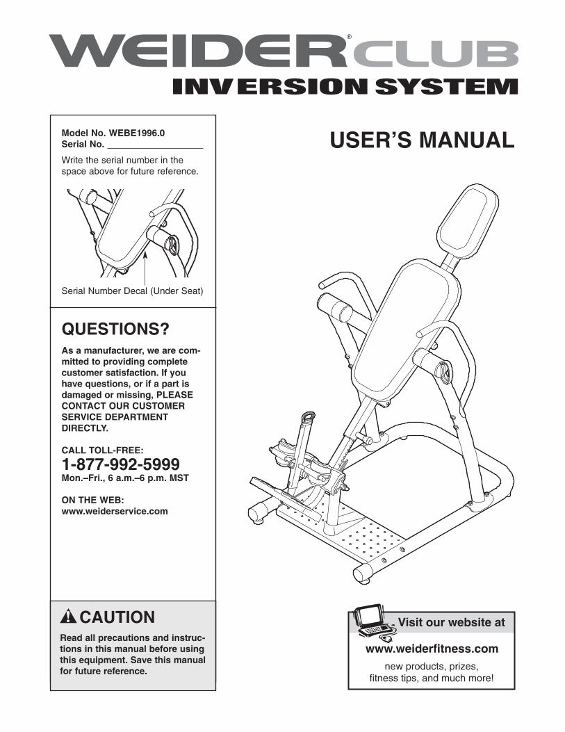
Model No. WEBE1996.0Serial No.
Write the serial number in thespace above for future reference.
Visit our website at
www.proform.comnew products, prizes,
fitness tips, and much more!
Visit our website at
www.healthrider.comnew products, prizes,
fitness tips, and much more!
Visit our website at
www.nordictrack.comnew products, prizes,
fitness tips, and much more!
Visit our website at
www.weiderfitness.comnew products, prizes,
fitness tips, and much more!
CAUTIONRead all precautions and instruc-tions in this manual before usingthis equipment. Save this manualfor future reference.
Serial Number Decal (Under Seat)
QUESTIONS?As a manufacturer, we are com-mitted to providing completecustomer satisfaction. If youhave questions, or if a part isdamaged or missing, PLEASECONTACT OUR CUSTOMERSERVICE DEPARTMENTDIRECTLY.
CALL TOLL-FREE:
1-877-992-5999Mon.–Fri., 6 a.m.–6 p.m. MST
ON THE WEB:www.weiderservice.com
USER’S MANUAL

2
IMPORTANT PRECAUTIONS . . . . . . . . . . . . . . . . . . . . . . . . . . . . . . . . . . . . . . . . . . . . . . . . . . . . . . . . . . . . . . . . 3BEFORE YOU BEGIN . . . . . . . . . . . . . . . . . . . . . . . . . . . . . . . . . . . . . . . . . . . . . . . . . . . . . . . . . . . . . . . . . . . . . . 4PART IDENTIFICATION CHART . . . . . . . . . . . . . . . . . . . . . . . . . . . . . . . . . . . . . . . . . . . . . . . . . . . . . . . . . . . . . .5ASSEMBLY . . . . . . . . . . . . . . . . . . . . . . . . . . . . . . . . . . . . . . . . . . . . . . . . . . . . . . . . . . . . . . . . . . . . . . . . . . . . . . 6ADJUSTMENT . . . . . . . . . . . . . . . . . . . . . . . . . . . . . . . . . . . . . . . . . . . . . . . . . . . . . . . . . . . . . . . . . . . . . . . . . . . 13ROTATING ON THE INVERSION TABLE . . . . . . . . . . . . . . . . . . . . . . . . . . . . . . . . . . . . . . . . . . . . . . . . . . . . . . 15DEVELOPING A PROGRAM . . . . . . . . . . . . . . . . . . . . . . . . . . . . . . . . . . . . . . . . . . . . . . . . . . . . . . . . . . . . . . . .16PART LIST . . . . . . . . . . . . . . . . . . . . . . . . . . . . . . . . . . . . . . . . . . . . . . . . . . . . . . . . . . . . . . . . . . . . . . . . . . . . . .18EXPLODED DRAWING . . . . . . . . . . . . . . . . . . . . . . . . . . . . . . . . . . . . . . . . . . . . . . . . . . . . . . . . . . . . . . . . . . . .19ORDERING REPLACEMENT PARTS . . . . . . . . . . . . . . . . . . . . . . . . . . . . . . . . . . . . . . . . . . . . . . . . . .Back CoverLIMITED WARRANTY . . . . . . . . . . . . . . . . . . . . . . . . . . . . . . . . . . . . . . . . . . . . . . . . . . . . . . . . . . . . . . Back Cover
TABLE OF CONTENTS
WEIDER is a registered trademark of ICON IP, Inc.

3
1. Read all instructions in this manual beforeusing the inversion table. Use the inversiontable only as described in this manual.
2. It is the responsibility of the owner to ensurethat all users of the inversion table are ade-quately informed of all precautions.
3. The inversion table is intended for home useonly. Do not use the inversion table in anycommercial, rental, or institutional setting.
4. Keep the inversion table indoors, away frommoisture and dust. Do not put the inversiontable in a garage or covered patio, or nearwater.
5. Use the inversion table only on a level sur-face. Cover the floor beneath the inversiontable to protect the floor.
6. Make sure that all parts are properly tight-ened each time the inversion table is used.Replace any worn parts immediately.
7. Keep children under 12 and pets away fromthe inversion table at all times.
8. The inversion table is designed to support amaximum user weight of 300 lbs. (136 kg).Do not use weights with the inversion table.
9. Always wear athletic shoes with laces to helpsecure your feet in the inversion table, andfor foot protection while exercising.
10. The inversion table should be used only bypersons 6 ft. 6 in. (198 cm) tall or less.
11. Keep hands and feet away from movingparts.
12. Always make sure that the ankle lock issecured snugly against your ankles and that
the short knob is fully tightened before youuse the inversion table.
13. Perform all activities on the inversion table ina slow, controlled manner. Aggressive exer-cise can cause the inversion table to tip over.
14. Always exercise with a partner. Your partnershould be ready to return the backrest to theupright position if you cannot complete therotation.
15. If you feel pain or dizziness while exercising,stop immediately and begin cooling down.
16. Following is a list of factors and conditionsthat may make inverting inadvisable (this listis not exhaustive; it is intended only for refer-ence). If one or more factors or conditionsapply to you, consult your physician beforeusing the inversion table.
• Pregnancy• Hiatal hernia or ventral hernia• Glaucoma, retinal detachment, or conjunc-
tivitis• High blood pressure, hypertension, or
recent stroke or transient ischemic attack• Heart or circulatory disorders for which
you are being treated• Middle ear infection and extreme obesity• Spinal injury, cerebral sclerosis, or acutely
swollen joints• Bone weakness (osteoporosis), recent
unhealed fractures, medullary pins, or sur-gically implanted orthopedic supports
• The use of anticoagulants, including highdoses of aspirin
17. The decal shown on page 4 has been placedon the inversion table. If the decal is missingor illegible, call the toll-free telephone num-ber on the front cover of this manual andorder a free replacement decal. Apply thedecal in the location shown.
WARNING: Before beginning this or any exercise program, consult your physician. Thisis especially important for persons over the age of 35 or persons with pre-existing health problems.Read all instructions before using. ICON assumes no responsibility for personal injury or propertydamage sustained by or through the use of this product.
WARNING: To reduce the risk of serious injury, read the following important precautionsbefore using the inversion table.
IMPORTANT PRECAUTIONS
4
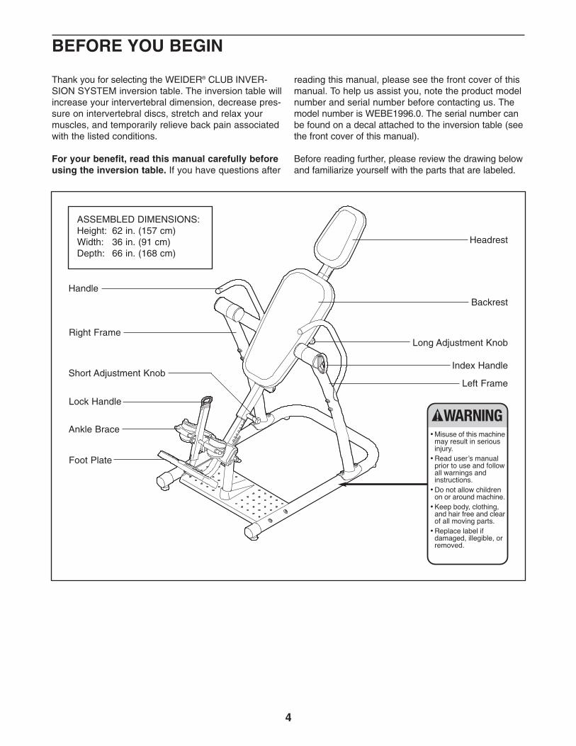
Handle
Left Frame
Long Adjustment Knob
Backrest
Headrest
Foot Plate
Ankle Brace
Lock Handle
Index HandleShort Adjustment Knob
Right Frame
ASSEMBLED DIMENSIONS: Height: 62 in. (157 cm)Width: 36 in. (91 cm)Depth: 66 in. (168 cm)
BEFORE YOU BEGIN
Thank you for selecting the WEIDER® CLUB INVER-SION SYSTEM inversion table. The inversion table willincrease your intervertebral dimension, decrease pres-sure on intervertebral discs, stretch and relax yourmuscles, and temporarily relieve back pain associatedwith the listed conditions.
For your benefit, read this manual carefully beforeusing the inversion table. If you have questions after
reading this manual, please see the front cover of thismanual. To help us assist you, note the product modelnumber and serial number before contacting us. Themodel number is WEBE1996.0. The serial number canbe found on a decal attached to the inversion table (seethe front cover of this manual).
Before reading further, please review the drawing belowand familiarize yourself with the parts that are labeled.
5
M10 NylonLocknut (65)
M8 NylonLocknut (72)
M6 Washer (62)
M4 x 15mmScrew (58)
M10 x 85mm Button Bolt (51)
M10 x 95mm Button Bolt (73)
M6 x 18mmButton Screw (55)
M6 x 55mm Button Screw (56)
M
M4 x 25mmScrew (60)
M4 x 30mmScrew (63)
M4 x 20mmScrew (71)
M10 Curved Washer (50)
M10 Washer (68)
M10 x 35mmButton Bolt (53)
M10 x 16mmButton Screw (54)
M10 x 75mm Button Bolt (57)
M10 x 80mm Button Bolt (52)
M10 x 53mm Button Bolt (49)
M8 x 16mmButton Bolt (61)
M5 x 25mmScrew (59)M10 Large Washer (64)
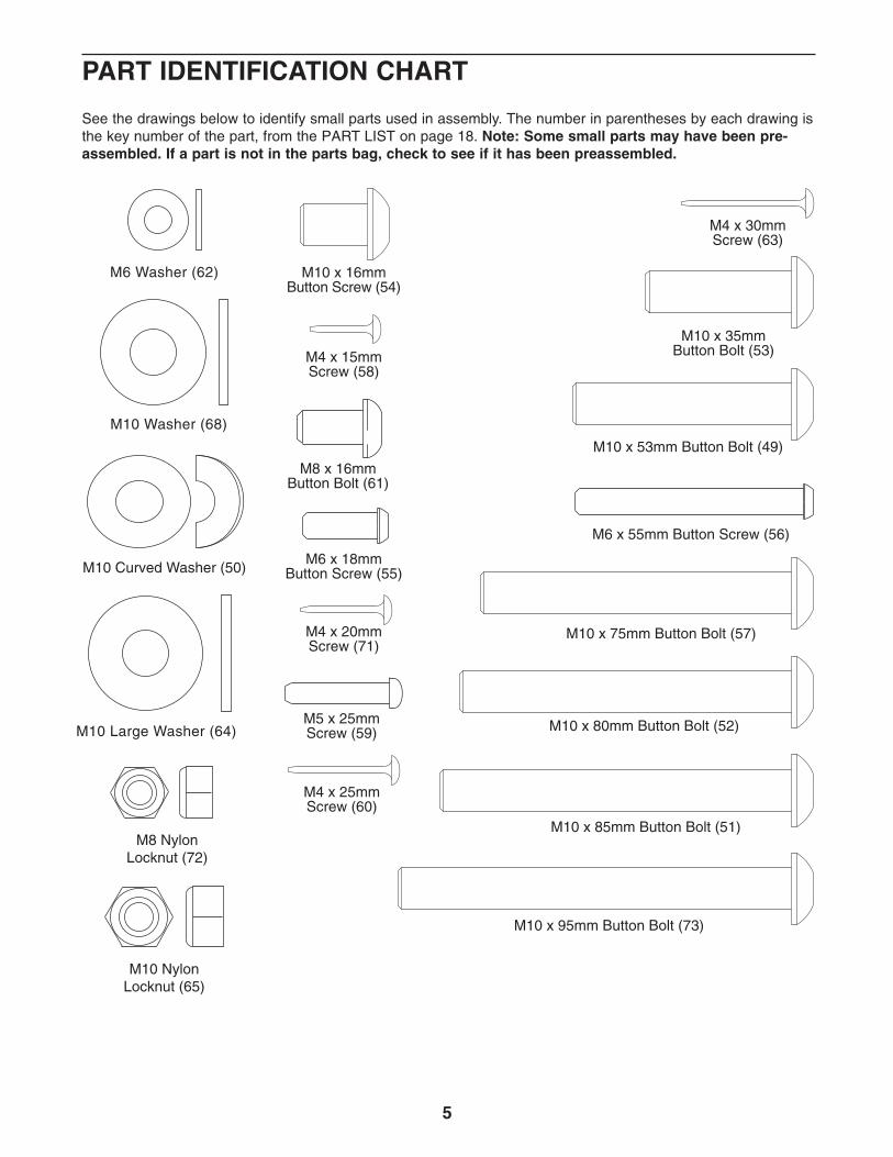
PART IDENTIFICATION CHART
See the drawings below to identify small parts used in assembly. The number in parentheses by each drawing isthe key number of the part, from the PART LIST on page 18. Note: Some small parts may have been pre-assembled. If a part is not in the parts bag, check to see if it has been preassembled.
6
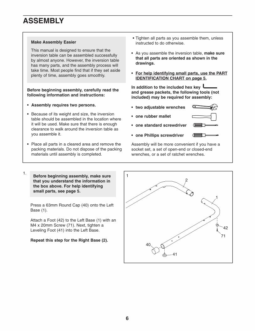
1.
Press a 63mm Round Cap (40) onto the LeftBase (1).
Attach a Foot (42) to the Left Base (1) with anM4 x 20mm Screw (71). Next, tighten aLeveling Foot (41) into the Left Base.
Repeat this step for the Right Base (2).
1Before beginning assembly, make surethat you understand the information inthe box above. For help identifyingsmall parts, see page 5.
1
71
42
2
41
40
Before beginning assembly, carefully read thefollowing information and instructions:
• Assembly requires two persons.
• Because of its weight and size, the inversiontable should be assembled in the location whereit will be used. Make sure that there is enoughclearance to walk around the inversion table asyou assemble it.
• Place all parts in a cleared area and remove thepacking materials. Do not dispose of the packingmaterials until assembly is completed.
• Tighten all parts as you assemble them, unlessinstructed to do otherwise.
• As you assemble the inversion table, make surethat all parts are oriented as shown in thedrawings.
• For help identifying small parts, use the PARTIDENTIFICATION CHART on page 5.
In addition to the included hex keyand grease packets, the following tools (notincluded) may be required for assembly:
• two adjustable wrenches
• one rubber mallet
• one standard screwdriver
• one Phillips screwdriver
Assembly will be more convenient if you have asocket set, a set of open-end or closed-endwrenches, or a set of ratchet wrenches.
Make Assembly Easier
This manual is designed to ensure that theinversion table can be assembled successfullyby almost anyone. However, the inversion tablehas many parts, and the assembly process willtake time. Most people find that if they set asideplenty of time, assembly goes smoothly.
ASSEMBLY
7
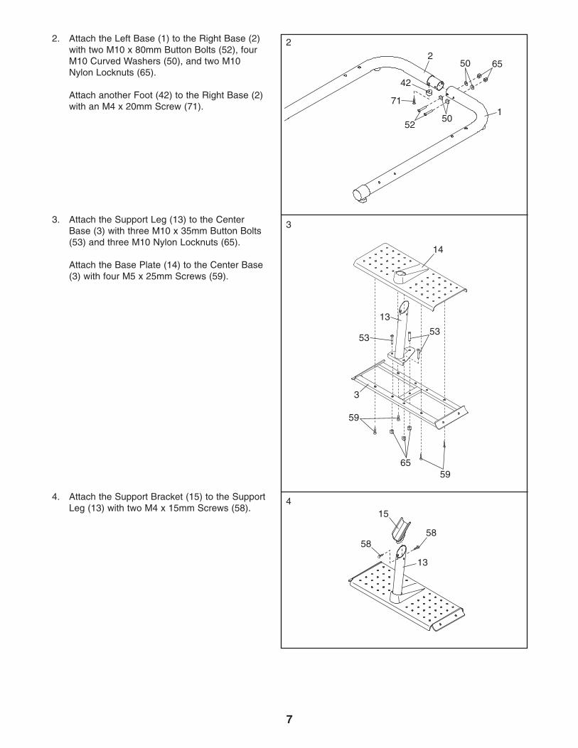
2. Attach the Left Base (1) to the Right Base (2)with two M10 x 80mm Button Bolts (52), fourM10 Curved Washers (50), and two M10Nylon Locknuts (65).
Attach another Foot (42) to the Right Base (2)with an M4 x 20mm Screw (71).
3. Attach the Support Leg (13) to the CenterBase (3) with three M10 x 35mm Button Bolts(53) and three M10 Nylon Locknuts (65).
Attach the Base Plate (14) to the Center Base(3) with four M5 x 25mm Screws (59).
4. Attach the Support Bracket (15) to the SupportLeg (13) with two M4 x 15mm Screws (58).
22
152
50
50 65
71
42
13
59
5965
53
3
53
14
3
13
5858
415
8
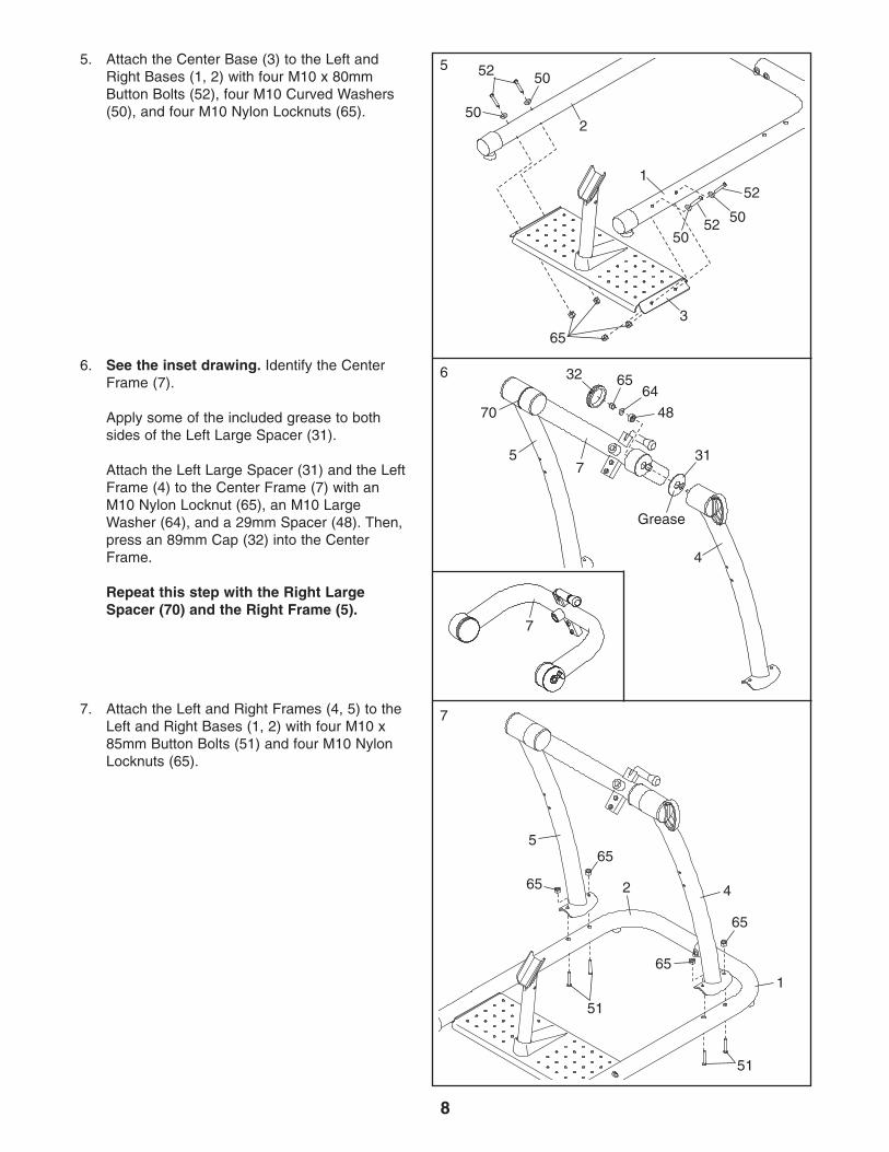
5. Attach the Center Base (3) to the Left andRight Bases (1, 2) with four M10 x 80mmButton Bolts (52), four M10 Curved Washers(50), and four M10 Nylon Locknuts (65).
6. See the inset drawing. Identify the CenterFrame (7).
Apply some of the included grease to bothsides of the Left Large Spacer (31).
Attach the Left Large Spacer (31) and the LeftFrame (4) to the Center Frame (7) with anM10 Nylon Locknut (65), an M10 LargeWasher (64), and a 29mm Spacer (48). Then,press an 89mm Cap (32) into the CenterFrame.
Repeat this step with the Right LargeSpacer (70) and the Right Frame (5).
7. Attach the Left and Right Frames (4, 5) to theLeft and Right Bases (1, 2) with four M10 x85mm Button Bolts (51) and four M10 NylonLocknuts (65).
5 52 50
50
3
65
5050
52
52
2
1
7
65
51
51
1
2
65
65
65
4
5
32 6564
48
4
731
Grease
70
5
6
7
9
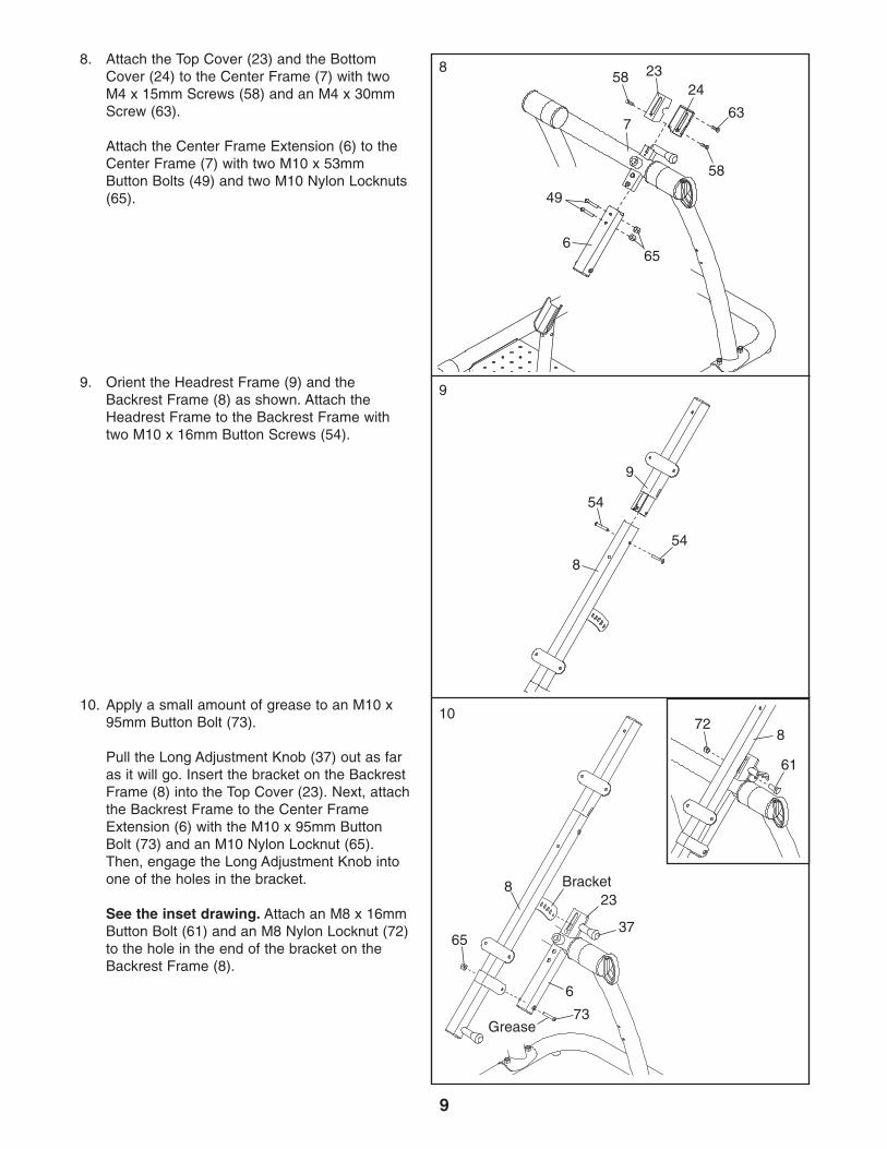
8. Attach the Top Cover (23) and the BottomCover (24) to the Center Frame (7) with twoM4 x 15mm Screws (58) and an M4 x 30mmScrew (63).
Attach the Center Frame Extension (6) to theCenter Frame (7) with two M10 x 53mmButton Bolts (49) and two M10 Nylon Locknuts(65).
8
7
58
58
63
2324
6
49
65
9. Orient the Headrest Frame (9) and theBackrest Frame (8) as shown. Attach theHeadrest Frame to the Backrest Frame withtwo M10 x 16mm Button Screws (54).
9
9
8
54
54
10. Apply a small amount of grease to an M10 x95mm Button Bolt (73).
Pull the Long Adjustment Knob (37) out as faras it will go. Insert the bracket on the BackrestFrame (8) into the Top Cover (23). Next, attachthe Backrest Frame to the Center FrameExtension (6) with the M10 x 95mm ButtonBolt (73) and an M10 Nylon Locknut (65).Then, engage the Long Adjustment Knob intoone of the holes in the bracket.
See the inset drawing. Attach an M8 x 16mmButton Bolt (61) and an M8 Nylon Locknut (72)to the hole in the end of the bracket on theBackrest Frame (8).
10
6
23Bracket
65
73Grease
8
37
61
872
10
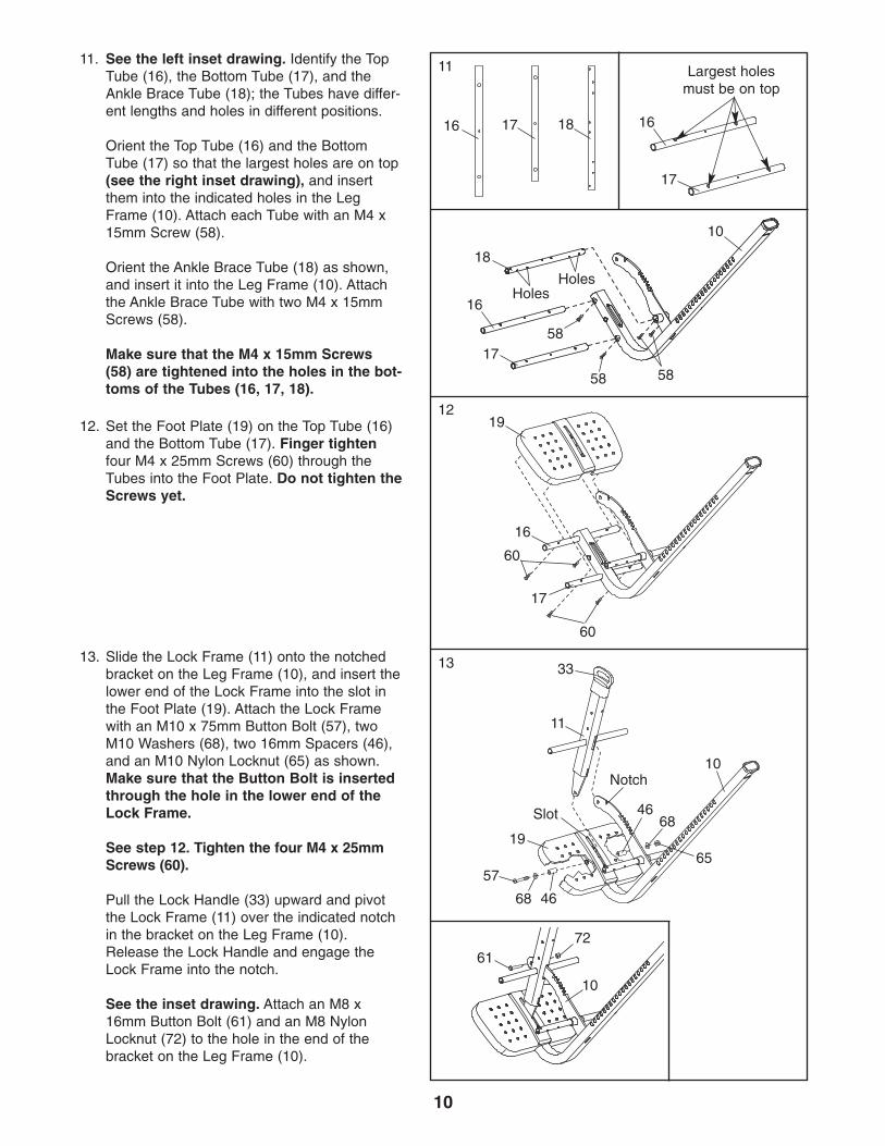
11. See the left inset drawing. Identify the TopTube (16), the Bottom Tube (17), and theAnkle Brace Tube (18); the Tubes have differ-ent lengths and holes in different positions.
Orient the Top Tube (16) and the BottomTube (17) so that the largest holes are on top(see the right inset drawing), and insertthem into the indicated holes in the LegFrame (10). Attach each Tube with an M4 x15mm Screw (58).
Orient the Ankle Brace Tube (18) as shown,and insert it into the Leg Frame (10). Attachthe Ankle Brace Tube with two M4 x 15mmScrews (58).
Make sure that the M4 x 15mm Screws(58) are tightened into the holes in the bot-toms of the Tubes (16, 17, 18).
12. Set the Foot Plate (19) on the Top Tube (16)and the Bottom Tube (17). Finger tightenfour M4 x 25mm Screws (60) through theTubes into the Foot Plate. Do not tighten theScrews yet.
13. Slide the Lock Frame (11) onto the notchedbracket on the Leg Frame (10), and insert thelower end of the Lock Frame into the slot inthe Foot Plate (19). Attach the Lock Framewith an M10 x 75mm Button Bolt (57), twoM10 Washers (68), two 16mm Spacers (46),and an M10 Nylon Locknut (65) as shown.Make sure that the Button Bolt is insertedthrough the hole in the lower end of theLock Frame.
See step 12. Tighten the four M4 x 25mmScrews (60).
Pull the Lock Handle (33) upward and pivotthe Lock Frame (11) over the indicated notchin the bracket on the Leg Frame (10).Release the Lock Handle and engage theLock Frame into the notch.
See the inset drawing. Attach an M8 x16mm Button Bolt (61) and an M8 NylonLocknut (72) to the hole in the end of thebracket on the Leg Frame (10).
17
16
5858
10
12
60
16
17
19
60
13
Notch
33
11
10
19
57
46
11
16 17
61
10
72
18
18
Holes
58
Slot
68
68
65
46
Holes
Largest holesmust be on top
17
16
11
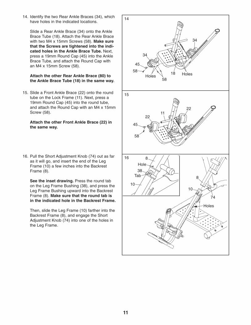
14. Identify the two Rear Ankle Braces (34), whichhave holes in the indicated locations.
Slide a Rear Ankle Brace (34) onto the AnkleBrace Tube (18). Attach the Rear Ankle Bracewith two M4 x 15mm Screws (58). Make surethat the Screws are tightened into the indi-cated holes in the Ankle Brace Tube. Next,press a 19mm Round Cap (45) into the AnkleBrace Tube, and attach the Round Cap withan M4 x 15mm Screw (58).
Attach the other Rear Ankle Brace (80) tothe Ankle Brace Tube (18) in the same way.
15. Slide a Front Ankle Brace (22) onto the roundtube on the Lock Frame (11). Next, press a19mm Round Cap (45) into the round tube,and attach the Round Cap with an M4 x 15mmScrew (58).
Attach the other Front Ankle Brace (22) inthe same way.
34
18 HolesHoles
34
58
58
45
15
58
22
2211
45
14
16. Pull the Short Adjustment Knob (74) out as faras it will go, and insert the end of the LegFrame (10) a few inches into the BackrestFrame (8).
See the inset drawing. Press the round tabon the Leg Frame Bushing (38), and press theLeg Frame Bushing upward into the BackrestFrame (8). Make sure that the round tab isin the indicated hole in the Backrest Frame.
Then, slide the Leg Frame (10) farther into theBackrest Frame (8), and engage the ShortAdjustment Knob (74) into one of the holes inthe Leg Frame.
8
10
74
Holes
16
10
38
8
Hole
Tab
12
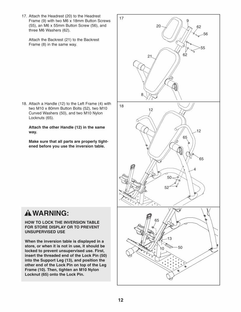
17. Attach the Headrest (20) to the HeadrestFrame (9) with two M6 x 18mm Button Screws(55), an M6 x 55mm Button Screw (56), andthree M6 Washers (62).
Attach the Backrest (21) to the BackrestFrame (8) in the same way.
17
20
21
8
62
62
18. Attach a Handle (12) to the Left Frame (4) withtwo M10 x 80mm Button Bolts (52), two M10Curved Washers (50), and two M10 NylonLocknuts (65).
Attach the other Handle (12) in the sameway.
Make sure that all parts are properly tight-ened before you use the inversion table.
18
65
50
52
12
12
65
4
56
55
9
50
13
65
10
WARNING:HOW TO LOCK THE INVERSION TABLEFOR STORE DISPLAY OR TO PREVENTUNSUPERVISED USE
When the inversion table is displayed in astore, or when it is not in use, it should belocked to prevent unsupervised use. First,insert the threaded end of the Lock Pin (50)into the Support Leg (13), and position theother end of the Lock Pin on top of the LegFrame (10). Then, tighten an M10 NylonLocknut (65) onto the Lock Pin.
13
This section explains how to adjust the inversion table. See DEVELOPING A PROGRAM on page 16 for impor-tant information about how to get the most benefit from the inversion table.
Make sure that all parts are properly tightened each time you use the inversion table. Replace any worn partsimmediately. The inversion table can be cleaned with a damp cloth and a mild, non-abrasive detergent. Do not usesolvents to clean the inversion table.
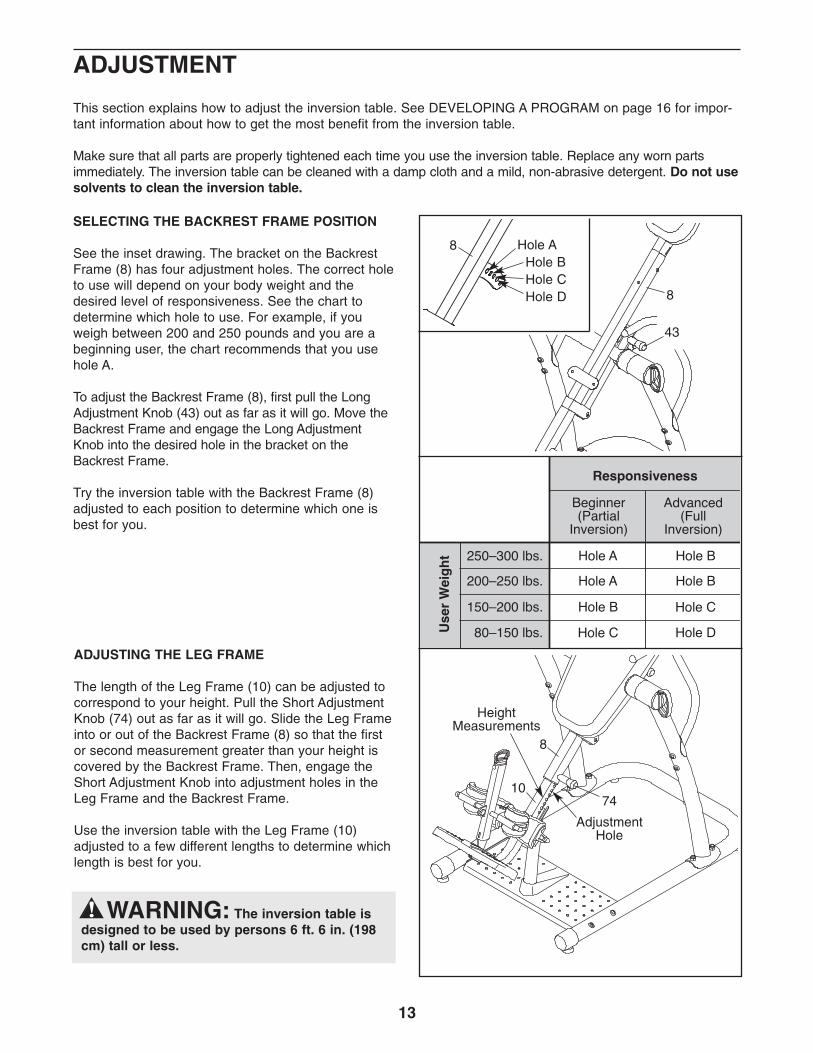
SELECTING THE BACKREST FRAME POSITION
See the inset drawing. The bracket on the BackrestFrame (8) has four adjustment holes. The correct holeto use will depend on your body weight and thedesired level of responsiveness. See the chart todetermine which hole to use. For example, if youweigh between 200 and 250 pounds and you are abeginning user, the chart recommends that you usehole A.
To adjust the Backrest Frame (8), first pull the LongAdjustment Knob (43) out as far as it will go. Move theBackrest Frame and engage the Long AdjustmentKnob into the desired hole in the bracket on theBackrest Frame.
Try the inversion table with the Backrest Frame (8)adjusted to each position to determine which one isbest for you.
8
43
Hole AHole B Hole CHole D 8
ADJUSTMENT
ADJUSTING THE LEG FRAME
The length of the Leg Frame (10) can be adjusted tocorrespond to your height. Pull the Short AdjustmentKnob (74) out as far as it will go. Slide the Leg Frameinto or out of the Backrest Frame (8) so that the firstor second measurement greater than your height iscovered by the Backrest Frame. Then, engage theShort Adjustment Knob into adjustment holes in theLeg Frame and the Backrest Frame.
Use the inversion table with the Leg Frame (10)adjusted to a few different lengths to determine whichlength is best for you.
WARNING: The inversion table isdesigned to be used by persons 6 ft. 6 in. (198cm) tall or less.
7410
8
AdjustmentHole
HeightMeasurements
14
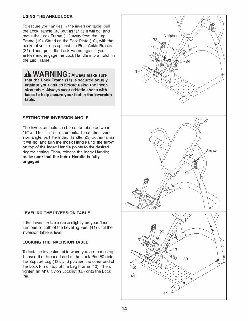
LEVELING THE INVERSION TABLE
If the inversion table rocks slightly on your floor,turn one or both of the Leveling Feet (41) until theinversion table is level.
LOCKING THE INVERSION TABLE
To lock the inversion table when you are not usingit, insert the threaded end of the Lock Pin (50) intothe Support Leg (13), and position the other end ofthe Lock Pin on top of the Leg Frame (10). Then,tighten an M10 Nylon Locknut (65) onto the LockPin.
SETTING THE INVERSION ANGLE
The inversion table can be set to rotate between15° and 90°, in 15° increments. To set the inver-sion angle, pull the Index Handle (25) out as far asit will go, and turn the Index Handle until the arrowon top of the Index Handle points to the desireddegree setting. Then, release the Index Handle;make sure that the Index Handle is fullyengaged.
11
33
19
25
Arrow
10
34
41
50
13
65
41
USING THE ANKLE LOCK
To secure your ankles in the inversion table, pullthe Lock Handle (33) out as far as it will go, andmove the Lock Frame (11) away from the LegFrame (10). Stand on the Foot Plate (19), with thebacks of your legs against the Rear Ankle Braces(34). Then, push the Lock Frame against yourankles and engage the Lock Handle into a notch inthe Leg Frame.
WARNING: Always make surethat the Lock Frame (11) is secured snuglyagainst your ankles before using the inver-sion table. Always wear athletic shoes withlaces to help secure your feet in the inversiontable.
Notches
10
15
This section explains how to rotate back on the inversion table, and then return to the starting position. Beforeusing the inversion table, see the ADJUSTMENT section starting on page 13 to correctly set up theinversion table. It may be helpful to have a second person ready to assist you as you learn to use the inversiontable.
ROTATING ON THE INVERSION TABLE
ROTATING BACK ON THE INVERSION TABLE
To rotate back on the inversion table, slowly lift yourarms over your head until you reach the desired posi-tion. The speed at which you lift your arms will deter-mine how quickly the inversion table will rotate. Restyour arms in a comfortable position that does notcause the inversion table to rotate. Note: The inversiontable will rotate only to the degree setting set by theindex handle.
ROTATING UP ON THE INVERSION TABLE
To return to the starting position, move your handstoward your waist until you rotate to a horizontal posi-tion. Rest in a horizontal position for 30 to 60 secondsbefore rotating to the starting position. This will allowyour body to readjust. Return to the starting positionslowly. Dizziness after using the inversion table is anindication that you have returned to the starting positiontoo quickly.
To rotate up from the fully inverted position, pull your-self up using the handles.
Do not sit up to return to the starting position.
16
BENEFITING FROM USING THE INVERSION TABLE
If you feel nauseated while using the inversion table,return to the starting position. Note that it may take afew weeks of use for your inner ear to become accus-tom to being inverted.
Do not use the inversion table right after you haveeaten.
Moving while using the inversion table may make it amore comfortable experience, and may help joints andmuscles stretch and relax. Always move in a slow, con-trolled manner.
The greater the angle at which the inversion table isused, the shorter the time that you should rotate backbefore rotating up. Increase the amount of inverted timeand the angle of use gradually.
Always pay attention to how your body feels as you usethe inversion table. Increase the level of intensity onlyas it is comfortable for you. When you feel like you havehad enough, return to the starting position.
BEGINNER PROGRAM
The following are suggestions for persons who are juststarting to use the inversion table.
Set the index handle to allow the backrest frame torotate to 15° or less for the first one or two weeks. Thiswill allow your body time to adjust to the change ingravitational pull.
Use the inversion table for one or two minutes at atime, two or three times a day.
Stay inverted only for as long as it is comfortable. Thismay be only a few seconds at first.
INTERMEDIATE PROGRAM
The following are suggestions for persons who havebecome comfortable using the inversion table asdescribed under the BEGINNER PROGRAM.
Increase the angle to which the inversion table canrotate, as it is comfortable. Adjust the index handle toallow the inversion table to rotate to up to 60°, a fewdegrees at a time.
Start to do gentle stretching while using the inversiontable.
Gradually increase the amount of time that you usethe inversion table to ten minutes or more, two orthree times a day. Routines can be varied from rotat-ing back for one or two minutes and then up for 30seconds, to rotating back and up for equal amounts oftime.
FULL INVERSION PROGRAM
The following are suggestions for persons who havebecome comfortable using the inversion table asdescribed under the INTERMEDIATE PROGRAM anddesire to rotate to greater angles. Note that all thebenefits of inversion can be gained by rotating to 60°.Do not attempt to do sit-ups.
Increase the angle to which the inversion table canrotate, as it is comfortable. Adjust the index handle toallow the inversion table to rotate until it comes in con-tact with the center frame.
Adjust the backrest frame so that the long adjustmentknob is in the top hole (see SELECTING THE BACK-REST FRAME POSITION on page 13). If you weigh220 lbs. (100 kg) or more, adjust the long adjustmentknob to the center hole in the backrest frame. Rotateback and up as described on page 15.
This section contains information and suggestions about using the inversion table. Make sure that all parts areproperly tightened each time you use the inversion table. Replace any worn parts immediately. See the ADJUST-MENT section starting on page 13 to identify parts referred to in this section.
DEVELOPING A PROGRAM

17
NOTES

18
Key No. Qty. Description Key No. Qty. Description
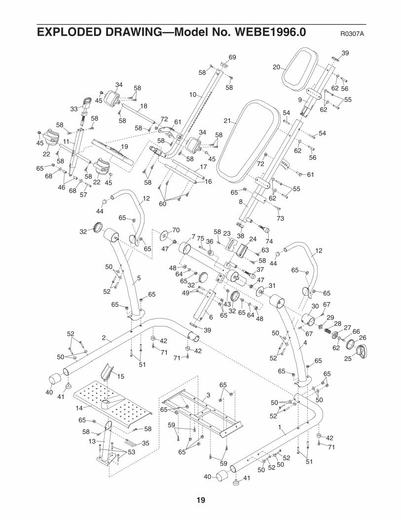
PART LIST—Model No. WEBE1996.0 R0307A
Note: “#” indicates a non-illustrated part. Specifications are subject to change without notice. See the back coverof this manual for information about ordering replacement parts.
1 1 Left Base2 1 Right Base3 1 Center Base4 1 Left Frame5 1 Right Frame6 1 Center Frame Extension7 1 Center Frame8 1 Backrest Frame9 1 Headrest Frame10 1 Leg Frame11 1 Lock Frame12 2 Handle13 1 Support Leg14 1 Base15 1 Support Bracket16 1 Top Tube17 1 Bottom Tube18 1 Ankle Brace Tube19 1 Foot Plate20 1 Headrest21 1 Backrest22 2 Front Ankle Brace23 1 Top Cover24 1 Bottom Cover25 1 Index Handle26 1 Index Ring27 1 Cup Washer28 1 Small Spring29 1 Cup Bushing30 1 Index Cup31 1 Left Large Spacer32 3 89mm Cap33 1 Ankle Lock Assembly34 2 Rear Ankle Brace35 1 Lock Pin36 1 Bumper37 1 Long Adjustment Knob38 1 Leg Frame Bushing39 2 42mm x 70mm Cap
40 2 63mm Round Cap41 2 Leveling Foot42 3 Foot43 1 M6 Nut44 2 32mm Round Cap45 4 19mm Round Cap46 2 16mm Spacer47 2 Pivot Bushing48 2 29mm Spacer49 2 M10 x 53mm Button Bolt50 12 M10 Curved Washer51 4 M10 x 85mm Button Bolt52 10 M10 x 80mm Button Bolt53 3 M10 x 35mm Button Bolt54 2 M10 x 16mm Button Screw55 4 M6 x 18mm Button Screw56 2 M6 x 55mm Button Screw57 1 M10 x 75mm Button Bolt58 20 M4 x 15mm Screw59 4 M5 x 25mm Screw60 4 M4 x 25mm Screw61 2 M8 x 16mm Button Bolt62 7 M6 Washer63 1 M4 x 30mm Screw64 2 M10 Large Washer65 24 M10 Nylon Locknut66 1 M6 x 15mm Screw67 2 M5 x 15mm Screw68 2 M10 Washer69 1 30mm x 60mm Cap70 1 Right Large Spacer71 3 M4 x 20mm Screw72 2 M8 Nylon Locknut73 1 M10 x 95mm Button Bolt74 1 Short Adjustment Knob75 1 M6 x 60mm Button Bolt# - User’s Manual# - Hex Key# - Grease Packet
EXPLODED DRAWING—Model No. WEBE1996.0 R0307A
1
2
3
4
5
6
7
8
910
11
12
12
13
14
15
16
17
18
19
20
21
34
34
22
22
2324
25
26
2728
29
30
31
32
32
7032
33
6939
38
40
40
41
41
42
42
42
74
3744
44
46
45
45
45
45
47
48
48
47
39
36
65
65
52
52
52
52
52
52
65
73
55
56
55
56
54
57
5858
58
5875
58
49
71
71
59
59
60
61
58
50 50
5050
50
50
50
62
62
65
6551
65
65
65
65
65
6572
65
6565
65
53
5458
58
58
6172
58
5868
68
51
65
65
65
67
67 66
64
64
43
58
58
63
58
62
62
62
58
58
58
35
71
19

Part No. 248912 R0307A Printed in China © 2007 ICON IP, Inc.
To order replacement parts, please see the front cover of this manual. To help us assist you, be prepared toprovide the following information when contacting us:
• the MODEL NUMBER of the product (WEBE1996.0)
• the NAME of the product (WEIDER CLUB INVERSION SYSTEM inversion table)
• the SERIAL NUMBER of the product (see the front cover of this manual)
• the KEY NUMBER and DESCRIPTION of the part(s) (see the PART LIST and the EXPLODED DRAWING onpages 18 and 19)
ORDERING REPLACEMENT PARTS
LIMITED WARRANTY
ICON Health & Fitness, Inc. (ICON) warrants this product to be free from defects in workmanship and mate-rial, under normal use and service conditions, for a period of ninety (90) days from the date of purchase. Thiswarranty extends only to the original purchaser. ICON's obligation under this warranty is limited to replacingor repairing, at ICON's option, the product through one of its authorized service centers. All repairs for whichwarranty claims are made must be pre-authorized by ICON. If the product is shipped to a service center,freight charges to and from the service center will be the customer’s responsibility. For in-home service, thecustomer will be responsible for a minimal trip charge. This warranty does not extend to any product or dam-age to a product caused by or attributable to freight damage, abuse, misuse, improper or abnormal usage orrepairs not provided by an ICON authorized service center; products used for commercial or rental purposes;or products used as store display models. No other warranty beyond that specifically set forth above is author-ized by ICON.
ICON is not responsible or liable for indirect, special or consequential damages arising out of or in connectionwith the use or performance of the product or damages with respect to any economic loss, loss of property,loss of revenues or profits, loss of enjoyment or use, costs of removal or installation or other consequentialdamages of whatsoever nature. Some states do not allow the exclusion or limitation of incidental or conse-quential damages. Accordingly, the above limitation may not apply to you.
The warranty extended hereunder is in lieu of any and all other warranties and any implied warranties of mer-chantability or fitness for a particular purpose is limited in its scope and duration to the terms set forth herein.Some states do not allow limitations on how long an implied warranty lasts. Accordingly, the above limitationmay not apply to you.
This warranty gives you specific legal rights. You may also have other rights which vary from state to state.
ICON HEALTH & FITNESS, INC., 1500 S. 1000 W., LOGAN, UT 84321-9813