model based tracking for augmented reality on …...model based tracking for augmented reality on...
TRANSCRIPT

Model Based Tracking for Augmented Realityon Mobile Devices
Michael LowneyDepartment of Electrical Engineering
Stanford UniversityStanford, CA 94305, USA
Email: [email protected]
Abhilash Sunder RajDepartment of Electrical Engineering
Stanford UniversityStanford, CA 94305, USAEmail: [email protected]
Abstract—In this paper we describe our methods for imple-menting real-time edge based tracking on an Android tablet.We implement a basic tracking algorithm, chosen for both itssimplicity and speed. . The performance of our system wasevaluated and its advantages and flaws have been pointed out.Suggestions for further improvement are made.
I. INTRODUCTION
In recent years, there has been a lot of interest in the fieldof Augmented Reality. With companies coming out withwearable AR headsets and AR mobile applications, thereis a pressing need for the development of real-time, highquality AR interfaces. Such interfaces would ideally involveachieving a seamless blend between the real world and the2D or 3D virtual objects projected onto it. This is a verychallenging technical problem which requires the rendering ofthe virtual objects to be both geometrically (correct placementof the objects, accurate scaling, detection of occlusions, etc.)and photometrically (shadowing, mutual reflections, adaptingto scene illumination, etc.) consistent.
The issue of correctly positioning virtual objects in the realworld scene can be solved by tracking the 3D environmentwith respect to the camera. Therefore, real-time camera poseestimation and tracking is a key part of augmented realityapplications. Broadly, all optical tracking methods can beclassified into two categories: marker-based tracking andmarker-less tracking. Marker-based tracking relies on artificialpatterns placed in the scene to estimate the camera pose.This category of methods has been well researched. Whilethese methods are fast and pretty robust, placing specializedmarkers in a natural scene is not ideal, especially for creatinga seamless blend between the real and virtual worlds. Assuch, most of the recent research in this area has been focusedon developing efficient marker-less tracking methods. Thisclass of methods makes use of natural features in the sceneto estimate the camera pose. On the downside, marker-lessAR is much more complicated and computationally expensive.
In this paper, we adopt a subset of marker-less tracking,namely a model-based tracking approach for solving theproblem. Model-based techniques make use of a known 3Dobject in the scene for estimating the pose of the camera.
Fig. 1. Taxonomy of model-based tracking methods for Augmented Reality
Unlike marker-based tracking, this class of tracking methodsdoes not rely on artificial patterns but rather on natural objectsfound in the scene. By tracking a simple cube placed in thescene, we show that model based tracking can be implementedin real-time on an Android based mobile device.
II. RELATED WORK
Model-based tracking can be classified into two categories:recursive tracking and tracking by detection (Fig.1). Inrecursive tracking, the previous camera pose is used as anestimate to calculate the current camera pose [2][4][5][7]. Dueto their recursive nature, they are not very computationallyexpensive and require relatively low processing power.Tracking by detection, on the other hand, can calculate thepose without any prior state knowledge [3][6], but thesemethods are usually computationally expensive and requirehigh processing power.
Recursive tracking techniques can be further classified intothree categories based on the type of feature used for tracking:edge-based methods, which tries to match a wire-frame 3Dmodel of the object with the edges of the real-world object[2]; optical flow based tracking, which uses the temporalinformation extracted from the relative movement of theobject’s projection in the image plane [4]; and texture-basedmethods, which uses the texture of the object for tracking

[5][7].
Tracking by detection is further classified into twocategories: edge-based methods, where the pose is calculatedby matching the current frame with 2D views of the object,previously obtained from various positions and orientations[3]; and texture-based methods, which uses keypoint (likeSIFT and SURF features) detection to calculate the camerapose in every frame [6].
In [1], the authors implement, evaluate and compare mul-tiple model-based tracking methods. The algorithm testingin all the above papers has been done on computers. Sinceour goal was to implement a real-time tracking system onan Android mobile device (which has limited computationalcapability), we decided to use an algorithm requiring relativelylow processing power. The algorithm implemented in thispaper is the Point Sampling algorithm, a recursive edge-basedtracking method.
III. METHODS
The full pipeline of the recursive edge-based tracking algo-rithm we implemented is shown in Fig. 2. Each stage of thealgorithm is explained below.
A. Camera Calibration
The first step of the implementation is camera calibration.Accurate camera calibration is essential since the algorithmlater uses the camera matrix in order to project the 3D modelof the object onto the 2D image plane. We calibrated ourcamera using the Camera Calibration Toolbox for MATLAB.The toolbox estimates the following camera parameters:
• The focal lengths of the camera in the x and y directions(denoted by fx and fy respectively).
• The position of the camera center in the image plane(given by cx and cy)
• The lens distortion (characterized by four variablesk,k2, k3 and k4.
Using these parameters, the 3 × 3 camera matrix, K can beconstructed as follows:
K =
fx 0 cx0 fy cy0 0 1
(1)
It is important to note that images taken with the Androidtablet’s camera app are different from the images that aredisplayed using the OpenCV Camera View. We believe this isdue to the fact that the camera app already knows the cameramatrix and applies some pre-processing to the raw imagecollected. It is for this reason that we collected the calibrationimages by taking screenshots of the OpenCV Camera View inorder to estimate the camera matrix.
B. Initial Pose Estimation
An initial pose of the object is required to start the trackingalgorithm. The 3D wire-frame model of the object is rotatedand translated into a pose that the user can easily view theobject from. The 3D model is then projected onto the imageplane using the following equation
pi = K[R|T ]Pi (2)
Where Pi is a 3D point (represented in homogeneous coordi-nates), K is the 3× 3 camera matrix, R is the 3× 3 rotationmatrix of the camera, T is the 3× 1 translation vector of thecamera, and pi is the projection of the 3D point onto the imageplane (in homogeneous coordinates). The outline of the objectis then drawn on the screen using the line() function inOpenCV. The user can align the outline with the actual objectand tap the screen to begin the tracking algorithm.
C. Visible Edge Detection
Once the pose is determined, the system must determinewhich edges of the object are visible, and which edges areoccluded. First, the model is rotated and translated accordingto the last known pose. Next, the normal vector for eachsurface is found. A dot product is taken between each normalvector and the vector from the camera to the surface inquestion. The sign of this dot product will be negative if theface is visible, and positive if the face is occluded. The visibleedges are chosen from the known visible faces. This methodworks well for our simple cube model, but more elaboratemethods are needed for complex shapes.
D. Control Points Sampling
With the visible edges of our model known, we must nextsample control points along these edges. Control points arepoints of interest on the model that will be compared to theincoming image from the camera. The sampling rate alongeach visible edge in the 3D model is proportional to theEuclidean distance of the projection of that edge in the imageplane. This ensures that the easily observable edges of ourmodel have more importance in our final pose estimation.The control points are sampled on the 3D model and labeledaccording to which edge they were sampled from.
E. Edge Map
The gradient information of the image is needed to estimatecorrespondences. In order to extract an edge map from thelatest image frame, we first blur the image with a Gaussianfilter to remove noise and to reduce the detection of falseedges in the scene. A 7x7 Gaussian kernel was applied witha standard deviation of 20. Once the image is blurred, Cannyedge detection is used to extract the edges from the image.Canny edge detection was chosen for its accuracy for detectingour object’s edges and its relatively fast computation time.

Fig. 2. Algorithm Pipeline
F. Correspondence Matching
In order to estimate the change in pose between successiveframes, we must find the correspondences between the 2Dpoints in the most recent frame to the 3D control points. First,the 3D control points are projected onto the image plane usingequation 2. Next we will determine what direction we mustsearch in to find a correspondence for each of the projectedcontrol points. Corresponding pairs are found by searching inthe direction orthogonal to the edge that each control pointlies on. The search directions are calculated based on theprojection of the model onto the image plane. To determine ifa point in the image is a correspondence, we will examine itsgradient information in the image extracted from Section III-E.A corresponding point is the closest pixel in the orthogonaldirection with a value of 1 in the edge map. If there is nocorresponding point within a fixed search distance then thecontrol point is removed and no longer used. In our applicationwe used a search distance of 25 pixels. Increasing the searchdistance allows for greater movement between frames, but hasthe potential to find false edges when the true edge is notdetected in the edge map.
G. Pose Estimation
Now that we have a set of correspondences between 3Dpoints on the model to 2D points in the current image frame,we can update our estimate of the rotation and translationof the 3D model. This is done by finding the rotation andtranslation that minimizes distance between the projected 3D
Fig. 3. Accurate tracking of cube
control points and their 2D correspondences as defined by thefollowing equation
[R|T ] = argmin[R|T ]
n∑i=0
d(pi,K[R|T ]Pi)2 (3)
where Pi is a point on the 3D model, pi is the estimated 2Dcorrespondence, and d is the Euclidean distance. The objectivefunction is minimized using OpenCV’s solvePnP() func-tion, which leverages the Levenberg-Marquardt algorithm tooptimize this non-linear equation.
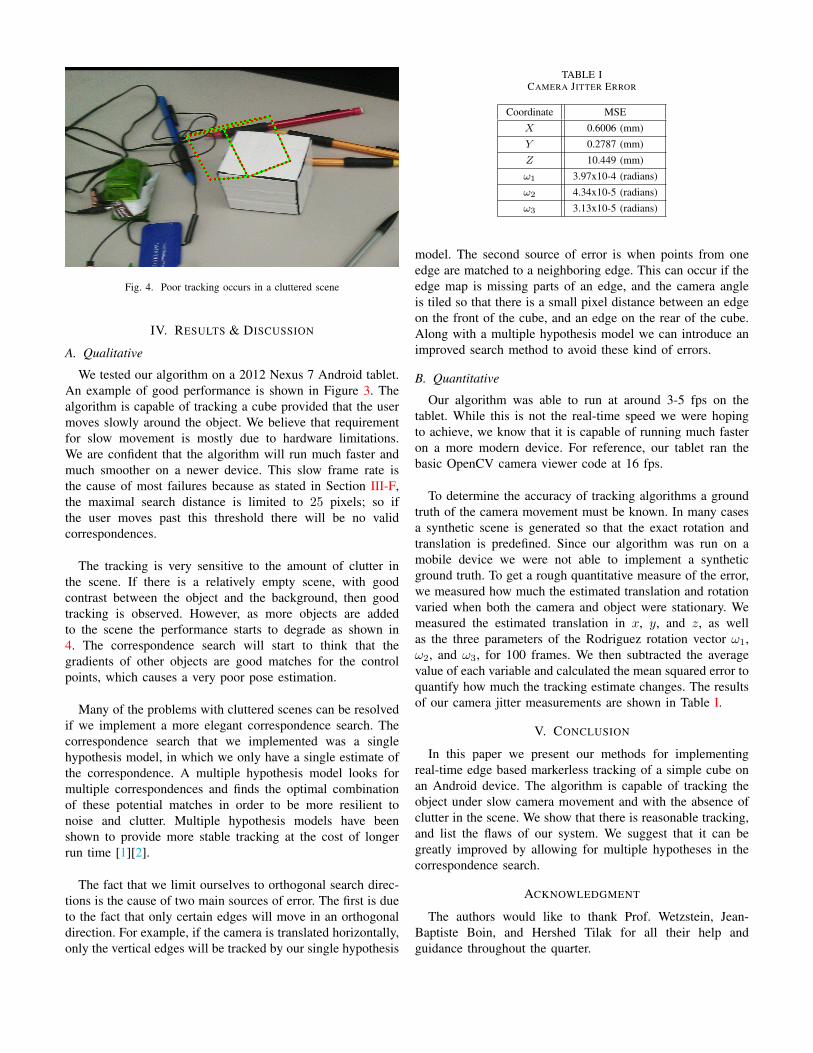
Fig. 4. Poor tracking occurs in a cluttered scene
IV. RESULTS & DISCUSSION
A. Qualitative
We tested our algorithm on a 2012 Nexus 7 Android tablet.An example of good performance is shown in Figure 3. Thealgorithm is capable of tracking a cube provided that the usermoves slowly around the object. We believe that requirementfor slow movement is mostly due to hardware limitations.We are confident that the algorithm will run much faster andmuch smoother on a newer device. This slow frame rate isthe cause of most failures because as stated in Section III-F,the maximal search distance is limited to 25 pixels; so ifthe user moves past this threshold there will be no validcorrespondences.
The tracking is very sensitive to the amount of clutter inthe scene. If there is a relatively empty scene, with goodcontrast between the object and the background, then goodtracking is observed. However, as more objects are addedto the scene the performance starts to degrade as shown in4. The correspondence search will start to think that thegradients of other objects are good matches for the controlpoints, which causes a very poor pose estimation.
Many of the problems with cluttered scenes can be resolvedif we implement a more elegant correspondence search. Thecorrespondence search that we implemented was a singlehypothesis model, in which we only have a single estimate ofthe correspondence. A multiple hypothesis model looks formultiple correspondences and finds the optimal combinationof these potential matches in order to be more resilient tonoise and clutter. Multiple hypothesis models have beenshown to provide more stable tracking at the cost of longerrun time [1][2].
The fact that we limit ourselves to orthogonal search direc-tions is the cause of two main sources of error. The first is dueto the fact that only certain edges will move in an orthogonaldirection. For example, if the camera is translated horizontally,only the vertical edges will be tracked by our single hypothesis
TABLE ICAMERA JITTER ERROR
Coordinate MSE
X 0.6006 (mm)
Y 0.2787 (mm)
Z 10.449 (mm)
ω1 3.97x10⁻⁴ (radians)
ω2 4.34x10⁻⁵ (radians)
ω3 3.13x10⁻⁵ (radians)
model. The second source of error is when points from oneedge are matched to a neighboring edge. This can occur if theedge map is missing parts of an edge, and the camera angleis tiled so that there is a small pixel distance between an edgeon the front of the cube, and an edge on the rear of the cube.Along with a multiple hypothesis model we can introduce animproved search method to avoid these kind of errors.
B. Quantitative
Our algorithm was able to run at around 3-5 fps on thetablet. While this is not the real-time speed we were hopingto achieve, we know that it is capable of running much fasteron a more modern device. For reference, our tablet ran thebasic OpenCV camera viewer code at 16 fps.
To determine the accuracy of tracking algorithms a groundtruth of the camera movement must be known. In many casesa synthetic scene is generated so that the exact rotation andtranslation is predefined. Since our algorithm was run on amobile device we were not able to implement a syntheticground truth. To get a rough quantitative measure of the error,we measured how much the estimated translation and rotationvaried when both the camera and object were stationary. Wemeasured the estimated translation in x, y, and z, as wellas the three parameters of the Rodriguez rotation vector ω1,ω2, and ω3, for 100 frames. We then subtracted the averagevalue of each variable and calculated the mean squared error toquantify how much the tracking estimate changes. The resultsof our camera jitter measurements are shown in Table I.
V. CONCLUSION
In this paper we present our methods for implementingreal-time edge based markerless tracking of a simple cube onan Android device. The algorithm is capable of tracking theobject under slow camera movement and with the absence ofclutter in the scene. We show that there is reasonable tracking,and list the flaws of our system. We suggest that it can begreatly improved by allowing for multiple hypotheses in thecorrespondence search.
ACKNOWLEDGMENT
The authors would like to thank Prof. Wetzstein, Jean-Baptiste Boin, and Hershed Tilak for all their help andguidance throughout the quarter.

REFERENCES
[1] Lima, J. Paulo, et al. ”Model based markerless 3D tracking applied toaugmented reality.” Journal on 3D Interactive Systems 1 (2010).
[2] Wuest, Harald, Florent Vial, and D. Strieker. ”Adaptive line trackingwith multiple hypotheses for augmented reality.” Fourth IEEE and ACMInternational Symposium on Mixed and Augmented Reality (ISMAR’05).IEEE, 2005.
[3] Wiedemann, Christian, Markus Ulrich, and Carsten Steger. ”Recognitionand tracking of 3d objects.” Joint Pattern Recognition Symposium.Springer Berlin Heidelberg, 2008.
[4] Basu, Sumit, Irfan Essa, and Alex Pentland. ”Motion regularization formodel-based head tracking.” Pattern Recognition, 1996., Proceedings ofthe 13th International Conference on. Vol. 3. IEEE, 1996.
[5] Vacchetti, Luca, Vincent Lepetit, and Pascal Fua. ”Stable real-time 3dtracking using online and offline information.” IEEE transactions onpattern analysis and machine intelligence 26.10 (2004): 1385-1391.
[6] Skrypnyk, Iryna, and David G. Lowe. ”Scene modelling, recognition andtracking with invariant image features.” Mixed and Augmented Reality,2004. ISMAR 2004. Third IEEE and ACM International Symposium on.IEEE, 2004.
[7] Jurie, Frdric, and Michel Dhome. ”A simple and efficient templatematching algorithm.” Computer Vision, 2001. ICCV 2001. Proceedings.Eighth IEEE International Conference on. Vol. 2. IEEE, 2001.
APPENDIX
The work for this project was distributed equally. Bothauthors were involved in all aspects of developing AndroidApp. A working demo of the Android App can be found at:https://youtu.be/-Ffzi-qL5Co.