model-based testing of ford’s lane keeping system
TRANSCRIPT

ConCept of the assistanCe system
The concept of Ford’s lane keeping system includes two variants: The driver can select a warning function and a lane keeping function in case the vehicle leaves its current lane, known as lane keeping alert, ❶, and lane keeping aid, ❷, respectively. Both functions make use of a camera serving as a sensor for identifying the traffic lane and the lane markings. Identifying the ve hicle’s own lane while continuously calculating the refer
ence steering angle as well as keeping the vehicle safely in its lane need to be assured by appropriate tests.
The lane keeping alert system is outlined in ①. The lane keeping alert function takes action by vibrating the steering wheel as an alert when the driver leaves his marked traffic lane.
The lane keeping aid system, ②, reacts earlier, exerting a superimposed steering torque. This must be “soft” and overrideable by the driver. The steering feeling and behaviour of this action are some
Dipl.-ing. Dirk guniais Group Leader and responsible for
the development of camera-based driver assistance systems at Ford-
Werke GmbH in Cologne (Germany).
Dipl.-ing. (fh) Jürgen sChülingis serving the customer Ford at
Berner & Mattner Systemtechnik GmbH in Cologne (Germany).
autHorS
figure © [M] Gregor Kervina / dreamstime.com
❶ Lane keeping alert in the assistance system
❷ Lane keeping aid in the assistance system
inDustry MeaSurInG and teStInG
28

Model-based TesTing of ford’s lane Keeping sysTeMdriver assistance systems improve road safety significantly, but the amount of applied quality assurance
requirements is immense and test results can necessitate modifications right up to the end. However,
late changes may cause increase in cost and delays in the project. Ford’s lane keeping system serves to
exemplify how model-based development – combined with a consistent test strategy – can help to exclude
error sources and reduce expensive prototype testing.
what akin to a manoeuvre used to drive the vehicle out of a rut.
The camera detects the vehicle’s position in the lane to enable the system to alert or intervene appropriately. Based on this position, the camera determines whether the vehicle is in a warning or intervention zone. There are some conditions that will always suppress the assistant as long as present, for instance, if a turn indicator is activated or the vehicle’s speed suggests that it is travelling in a city area. The assistant’s steering actions must on no account irritate, meaning that the control unit should not generate an uncontrollable torque even if the power steering system fails.
test series in every phase
Ford’s lane keeping system was developed in a modelbased fashion. Among other things, this method facilitates splitting the developments work up between the OEM and the tier1 supplier. The lane keeping system (LKS) comprises three functional blocks developed by Ford, ❸: The “LKS Controller” determines whether an intervention should take place and then calculates all signals needed for the steering system and the instrument cluster. On the side of the steering system, Ford developed the “LKS steer torque manager” for the lane keeping system. This functional unit
determines whether an alert or an intervention by the steering system can be carried out, and if the latter is the case, which steering torque levels should be used. Finally, the “LKS signal conditioner” enables to customise and use the other two functional blocks for multiple vehicle platforms and a range of different electrical architectures.
moDel-in-the-loop tests
In every development phase, errors can creep in that will only be identified by testing. The later this happens, the more expensive it will be to correct the error. If one approaches the development using models, it is possible to verify in an early phase whether the underlying behaviour
❸ distribution of the development processes in the Ford company for the lane keeping system (LKS) – with Ford-typical denotations
11I2011 Volume 113 29
assumptions, algorithms, and procedures apply and the system will behave as ex pected. Virtual integration of control unit functionality and environment models enables to analyse distributed functions in an early stage of the development process and eliminate design errors rapidly and costeffectively.
Using realistic environment simulations, the Messina test platform from Berner & Mattner allows to conduct systemised tests of control unit functionality developed in a modelbased way. In this way, the platform provides developers and testers with a powerful framework including modelbased simulation, vir
tual integration, and automated test series.
The functional models of Ford’s lane keeping system were integrated into the platform Messina in the sense of a ModelintheLoop (MiL). The functional model simulation was performed using the Tesis’ Dyna4 suite. This environment simulation was also integrated into the platform. It simulated the hostvehicle and the traffic lane geometry. A range of different test scenarios were generated by varying appropriate parameters, enabling the environment model to provide the lane keeping system functional model with signal se quences. The lane keeping system models were simulated and tested realistically in real time using the platform. These MiL tests allow complex timing and signal sequence analyses, which can later be reused in HardwareintheLoop (HiL) component tests.
training on virtual roaDs
The camera control unit was subjected to an extensive HiL test. First, scenarios were identified in order to formulate test parameters with a potential influence on the system. These are, for instance: : road parameters: road curvature, number
of traffic lanes, lane width, roadside, uphill or downhill road slope
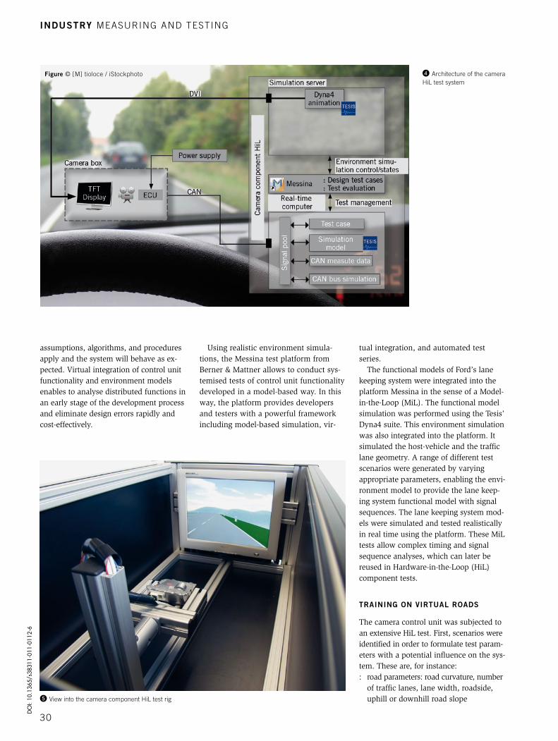
❹ architecture of the camera HiL test system
❺ View into the camera component HiL test rig
figure © [M] tioloce / iStockphoto
inDustry MeaSurInG and teStInG
30
DO
I: 10
.136
5/s3
8311
-011
-011
2-6

: lane marking parameters: lane marking availability, lane marking quality/contrast, lane marking type, lane marking colour, lane marking width, irritations (cross walks, tar strips, road junctions, etc.)
: hostvehicle parameters: driving manoeuvres, vehicle’s pitch angle, vehicle’s roll angle, vehicle speed
: ambient parameters: daytime/nighttime, rapid light transitions (tunnels, bridges, etc.), shadows on the lane (bridges, buildings, etc.).
The development team at Ford made use of the classification tree editor, CTE XL by Berner & Mattner, to generate meaningful test scenarios from the multitude of possible parameter value combinations, to optimise test coverage, and exclude duplicates. An advantage of this editor was that the test scenarios generated while using it were able to generate test cases directly in Messina. These were then automatically tested in sequence in the camera component HiL. This included the camera with its control unit containing the image pro cessing algorithms needed for implementing the lane keeping system. ❹ shows the camera HiL test system’s architecture.
The control unit was connected via CAN bus to the HiL realtime computer, which simulated the remaining vehicle bus for the control unit. During test operations, the Messina HiL system recorded the control unit’s output via the CAN communication, ensuring the availability of the information recorded and analysed by the camera control unit at all times.
The camera – shielded from external influences by a box – was placed in front of a TFT display, which played the synthesised scenarios to it. The simulation PC was the third component apart from the MessinaHiL system and the camera en closure along with the TFT display. It also served for operating the camera test rig, ❺, and exchanging data such as test case scenario parameters with the HiL test system.
Two kinds of tests were conducted: On the one hand, a qualitative test determined whether the lane keeping system was basically functional. This involved provoking reactions of the lane keeping system by means of the vehicle manoeuvres deposited in the test cases. Depending on whether it reacted with the expected out
put result or not, the test case was deemed to be passed or failed, respectively.
The quantitative test, as shown in 6, on the other hand, compared the reactions stimulated using the camera with those triggered in the MiL setup using the respective parameters. This enabled to draw on the respective functional model’s output as a reference for the test analysis to evaluate the control unit’s output.
ConClusion
Evidently, a simulation can only partly replace final driving tests, which assess the camera’s behaviour in incoming light or fog conditions, for instance. The aim was to create scenarios reproducible at any time. This enables to send each software version through all test scenarios. The ability to test models, software, and hardware again and again largely automatically and concurrently with the development helps resolve emerging issues at an early stage. And then, a documented optimisation evolution track is available at every stage of the development.
Moreover, the modelbased procedure and Messina’s MiLHiL consistency allow to generate reference data – without much effort for the quantitative test approach. Ford and Berner & Mattner have delivered a text book example with the described
use case, answering a significant part of the necessary test questions in early development stages.
referenCes[1] Gunia, d.; Plaumert, r.; tatschke, t.: der Spurhalteassistent von Ford – vom Konzept bis zur Verifikation. Lecture, aachener Kolloquium Fahrzeug- und Motorentechnik, aachen 2010[2] dittel, t.; aryus, H.-J.: How to “Survive” a Safety Case according to ISo 26262. In: Proceed-ings of the 29th International Conference on Com-puter Safety, reliability, and Security (Safecomp 2010), Vienna, austria, September 14-17, 2010, Series: Lecture notes in Computer Science, Springer-Verlag, Heidelberg, 2010
❻ Quantitative test setup
11I2011 Volume 113 31