lane departure warning system confirmation test … · lane departure warning system . confirmation...
TRANSCRIPT
LANE DEPARTURE WARNING SYSTEM CONFIRMATION TEST
And
Lane Keeping Support
Performance Documentation
February 2013 Office of Vehicle Safety
Office of Crash Avoidance Standards 1200 New Jersey Avenue, SE
Washington, DC 20590
2
LANE DEPATURE WARNING SYSTEM CONFIRMATION TEST AND
Lane Keeping Support Performance Documentation
TABLE OF CONTENTS
1.0 PURPOSE AND APPLICATION ........................................................................... 3
2.0 GENERAL REQUIREMENTS .............................................................................. 3
3.0 SECURITY ........................................................................................................... 3
4.0 GOOD HOUSEKEEPING ..................................................................................... 5
5.0 TEST SCHEDULING AND MONITORING ........................................................... 5
6.0 TEST DATA DISPOSITION ................................................................................. 5
7.0 VEHICLES AND EQUIPMENT AQUISITION ....................................................... 8
8.0 INSTRUMENTATION AND CALIBRATION.………………………………………...6 9.0 PHOTOGRAPHIC DOCUMENTATION ............................................................. 12
10.0 DEFINITIONS .................................................................................................... 14
11.0 PRETEST AND FACILITY REQUIREMENTS .................................................... 14
12.0 TEST EXECUTION AND TEST REQUIREMENTS ............................................ 22
13.0 POST TEST REQUIREMENTS ......................................................................... 29
14.0 REPORTS .......................................................................................................... 30
15.0 DATA SHEETS .................................................................................................. 36
16.0 REFERENCES ................................................................................................... 39
3
1.0 PURPOSE AND APPLICATION This laboratory test procedure provides the specifications for confirming the existence of Lane Departure Warning (LDW) hardware on light vehicles with gross vehicle weight ratings (GVWR) of up to 10,000. Current LDW technology relies on sensors to recognize a lane delimiting edge line. As such, the test procedures described in the document rely on painted or taped lines being present on the test course to emulate those found on public roadways. Although it is impossible to predict what technologies could be used by future LDW systems (e.g., magnetic markers, RADAR reflective striping, ultra violet paint, infrared, etc.), it is believed that minor modifications to these procedures, when deemed appropriate, could be used to accommodate the evaluation of alternative or more advanced LDW systems. In addition to being equipped with LDW systems to passively alert the driver of impeding lane departures, some vehicles are equipped with technology designed to actively mitigate lane departures. In this document, these systems are referred to as Lane Keeping Support (LKS) systems. The requirements of this indicant test procedure must be strictly adhered to. The Contractor's in-house test procedure must have NHTSA approval prior to conducting the first test of a particular fiscal year program. The Contractor's test procedure cannot deviate in any way from the NHTSA procedure without the prior approval of the NHTSA COTR. 2.0 GENERAL REQUIREMENTS The LDW tests described in this document are to be conducted at one constant test speed 45 mph (72 km/h), two different departure directions, to the left and right, and with three different styles of roadway markings, continuous white lines, discontinuous yellow lines, and discontinuous raised pavement markers. Each test condition shall be repeated until five (5) valid tests per condition are produced. If more than five (5) valid tests are performed, the Pass/Fail criteria for LDW shall be determined using the first five (5) valid tests performed. LDW performance is evaluated by considering the proximity of the vehicle with respect to the edge of a lane line at the time of the LDW alert. This document also includes language specifying how LKS tests may be performed to supplement the LDW performance evaluations. These supplemental tests are performed for informative purposes only, intended to expand NHTSA’s knowledge of how such systems operate. Conduct of the supplemental LKS tests will not confound a vehicle’s LDW assessment, nor will the data output from the LKS tests affect the vehicles NCAP LDW evaluation. 3.0 SECURITY

4
The Contractor shall provide appropriate security measures to protect test vehicles and equipment during the entire test program, and shall be responsible for all equipment removed from test vehicles before and after the test. Vehicle equipment thefts or act of vandalism must be reported to NHTSA authorities immediately. Under no circumstances shall any vehicle components be removed during a visitor inspection unless authorized by Office of Crash Avoidance Standards (OCAS) engineers. All data developed from the test program shall be protected. NO INDIVIDUALS other than the Contractor's personnel directly involved in the test program shall be allowed to witness a test, inspect, or photograph any test vehicle unless authorization is granted by a representative from the OCAS. It is the Contractor's responsibility to secure the test site area during a test. Rules for Contractors
A. No vehicle manufacturer's representative(s), or anyone other than the Contractor's personnel working on the contracts and NHTSA personnel, shall be allowed to inspect NHTSA vehicles or witness vehicle preparations and/or testing without prior permission of the OCAS. Such permission can never be assumed.
B. All communications with vehicle manufacturers shall be referred to the OCAS,
and at no time shall the Contractor release test data without the permission of the OCAS.
C. Unless otherwise specified, the vehicle manufacturer's representatives shall only be authorized to visit the Contractor's test facility on the day that the test is scheduled, and the representatives must be escorted by NHTSA and/or Contractor personnel.
D. Test vehicle inspection by the vehicle manufacturer's representative(s) shall be limited to 30 minutes prior to the start of vehicle test. Post-test inspection shall be limited to 1 hour after Contractor personnel have completed their test tasks.
E. Photographs and videos of the test vehicle, associated test equipment and test
event shall be allowed. However, test personnel shall not be included in any photographic coverage, and videotaping of vehicle preparation must be approved by OCAS. The Contractor's personnel shall not respond to any questions from the manufacturer's representatives regarding this test program. All questions shall be referred to the COTR, an OCAS representative present at the test site, or to OCAS.
F. The Contractor shall permit public access to and inspection of the test vehicles
and related data during the times specified by the NHTSA COTR. NHTSA shall advise interested parties that such access and inspection shall be limited to a specified day, and specified hours and require prior approval from the OCAS.

5
The Contractor shall refer all visit requests from vehicle manufacturer's representatives and consumers to the OCAS. This service shall be included as an incidental part of the test program and will not result in any additional cost to NHTSA. The Contractor shall make his own arrangements with interested parties for expenses incurred beyond providing access and inspection services. All inquiries by manufacturers concerning the test program (vehicle, procedures, data, etc.) shall be directed to OCAS representatives.
4.0 GOOD HOUSEKEEPING The Contractor will maintain the entire test area, vehicle pre-test preparation facility, instrumentation building, and equipment configuration and performance verification test laboratory in a clean, organized and painted condition. All test instrumentation must be setup in an orderly manner consistent with good engineering practices.
5.0 TEST SCHEDULING AND MONITORING The Contractor shall commence testing within four (4) weeks after receipt of the first test vehicle. Subsequent tests will be conducted, if requested, at a minimum of one (1) vehicle test per week. The NHTSA COTR will make adjustments to the test schedule in cases of unusual circumstances such as inclement weather or difficulty experienced by the Agency in the procurement of a particular vehicle make and model. All testing shall be coordinated to allow monitoring by the COTR.
6.0 TEST DATA DISPOSITION The Contractor shall make all test data available within two hours after the test event if so requested by Agency personnel. Under no circumstances shall this preliminary data be furnished to non-Agency personnel. The Contractor shall analyze the preliminary test results as directed by the COTR. 6.1 Computer Data and Final Hard-Copy
The Contractor shall deliver to OCAS the final data, presented on a CD or DVD, digital printouts, and plots within one (1) week after the LDW test.
6.2 Test Report 6.2.1 Test report shall include all of the items shown in the Sample Test Report. The
Contractor shall submit eleven (11) CD’s and one (1) paper copy of the test report to the following address:
U. S. Department of Transportation National Highway Traffic Safety Administration Office of Crash Avoidance Standards (NVS-120) 1200 New Jersey Avenue, SE, Room W43-478 Washington, DC 20590

6
6.2.2 Report Submission
All final test reports shall be submitted to the above listed NHTSA office within four (4) weeks from the date of the LDW test.
6.2.3 Text/Data Sheet CD
The Contractor shall submit one (1) CD or DVD of the text and data sheet portion only of the test report in Microsoft Word format within four (4) weeks from the date of the vehicle test. The full test report including photographs and data traces on a disk may be a future requirement.
6.3 Test Video
OCAS shall receive one (1) copy of the color videos or movies from each camera described in Section 9 and for each test described in S12, and the copies shall be mailed directly to the OCAS within four (4) weeks of the vehicle test. The master print for each of the LDW and the LKS test videos shall be retained by the Contractor, but will be made available to the OCAS upon request.
6.4 Data Loss 6.4.1 Conditions for Retest
The test vehicle is instrumented in order to obtain data needed. The data from tests, specifically from those channels providing lateral velocity and steering wheel angle are absolutely essential to the test program. An invalid test is one which does not conform precisely to all requirements/specifications of the laboratory test procedure and Statement of Work applicable to the test.
The contracting officer of NHTSA is the only NHTSA official authorized to notify the Contractor that a retest is required.
No test report is required for any test which is determined to be invalid unless NHTSA specifically decides to require the Contractor to submit such report. Invalidated test reports will not be publicly released.
7
_____________________________________________________________________
RETEST CONDITIONS
Failure of the Contractor to obtain the above data and to maintain acceptable limits of test parameters in the manner outlined in this test procedure shall require a retest at the expense of the Contractor and will include the cost of the vehicle replacement and retest at the Contractor's expense. The provisions of this paragraph apply to, but are not limited to, the Contractor maintaining proper speed tolerance, and test data acquisition, reduction, and processing. The Contractor shall also be responsible for obtaining usable data from all primary channels. Failure to produce such data shall also be at the expense of the Contractor and shall include vehicle replacement and retest unless the Office of Crash Avoidance Standards determines that the data loss occurred through conditions beyond reasonable and foreseeable control of the Contractor. Should it become necessary for the Contractor to procure another test vehicle, it must have identical equipment and options as the original vehicle. The retested vehicle shall be retained without fee by the testing facility until its disposal is authorized by the COTR. _____________________________________________________________________ 6.4.2 Conditions for Partial Payment
The Contractor shall exercise reasonable and foreseeable control to insure that no data is lost or rendered useless. If some non-critical data (such as camera failure) and critical data (vehicle position data) are not obtained and the test is accepted by the Agency, the Agency will not pay for the missing or lost data.
6.5 Data Retention by Contractor
The Contractor shall retain at no extra cost to the agency, reproducible copies of all data tapes (analog and digital), videos, and still photograph negatives or electronic files.
6.6 Data Availability to the Public
The Contractor shall provide interested parties with copies of test report, test CD’s, test data tapes, test films, and test still photographs, at a reasonable cost to the purchaser, but only after the Office of Crash Avoidance Standards representative has advised the Contractor that the results of that particular test have been released to the public by the Agency.
6.7 Indicant Failure Notification
Any indication of a “test failure” shall be communicated by telephone to COTR

8
within 24 hours of the test. NOTE: In the event of a failure, a post-test calibration check of some critically sensitive test equipment and instrumentation may be required for verification of accuracy. The necessity for the calibration shall be at the COTR's discretion and shall be performed without additional cost to the OCAS.
7.0 VEHICLES AND EQUIPMENT AQUISITION 7.1 Acceptance of Test Vehicles
The Contractor has the responsibility of accepting leased or NHTSA-provided test vehicles from either new car dealers or vehicle transporters. In both instances, the Contractor acts in the Agency’s behalf when signing an acceptance of test vehicles. The Contractor must check to verify the following:
A. All options listed on the “window sticker” are present on the test vehicle.
B. Wheels and tires are the same as listed.
C. There are no dents or other interior or exterior flaws.
D. The vehicle has been properly prepared and is in running condition.
E. The spare tire, jack, lug wrench, and tool kit (if applicable) are located in the vehicle cargo area.
The Contractor shall check for damage that may have occurred during transit or prior use. The COTR is to be notified of any damage prior to preparation of the vehicle for testing.
7.2 Notification of COTR The COTR must be notified within 24 hours after a vehicle has been delivered. 7.3 Government Furnished Equipment (GFE) No government furnished equipment will be available or provided to conduct the LDW tests. 8.0 INSTRUMENTATION AND CALIBRATION 8.1 Test Equipment
A. Portable tire pressure gage with an operating pressure of at least 700kPa (100 psi), graduated increments of 1.0 kPa (0.1 psi) and an accuracy of at least + 2.0% of the applied pressure.

9
B. Global Positioning System (GPS), comprised of a base station and rover, with post-processing software. Hardware and software solution shall provide position data (latitude and longitude) with at least 0.4 in (1.0 cm) of static accuracy (Novatel ProPak-V3 and Waypoint GrafNav or equivalent), and update at a rate of at least 10 Hz.
C. Data acquisition system to record the LDW alert status (on or off), time, GPS
data, and a yaw rate sensor. GPS data shall be collected with a sample rate of at least 20 Hz. Since the CAN broadcast rate is a vehicle-dependent (e.g., subject to update rate, bus traffic, prioritization, etc.), specifying a sample rate to collect CAN data is not possible. Rather, CAN data shall be sampled as it is transmitted by the vehicle.
D. Signal conditioning shall consist of amplification, anti-alias filtering (optional
on alert channels), and digitizing. Amplifier gains are to be selected to maximize the signal-to-noise ratio of the digitized data. A power spectrum density (PSD) analysis of analog alert channels should be performed prior to data capture in order to determine the dominant frequency for these channels.
E. Filter Design
i. Digital data obtained from a GPS/Inertial Measurement Units (IMU) that has already had anti-alias filtering applied does not need any further filtering assuming the data is in real time (updates of 10 milliseconds and a latency of 3.5 milliseconds)
ii. Anti-alias filtering should be performed on analog data obtained from a GPS/IMU and designed using the following minimum specifications:
a. The minimum sampling rate should be 400 Hz and a multiple of 200 Hz
i. If the channel is an alert channel, then the minimum sampling rate of alert channels should be four (4) times the frequency determined in the PSD
b. Passband should be set between zero (0) and five (5) Hz c. Signal error as a result from passband ripples should be less
than 1%. d. Stopband frequencies should be attenuated to less than 1%.
iii. Anti-alias filtering does not need to be performed on alert channels. If anti-aliasing is performed on alert channels, follow the minimum specifications listed above. The absolute value of alert channels is not the desired variable; instead the time of onset (the TTC) is of interest.
a. If anti-alias filtering is not performed: i. The minimum sampling rate of alert channels should be
four (4) times the frequency determined in the PSD
10
ii. Data shall be filtered using a phase-less, narrowband filter to distinguish the actual signal from background noise
1. Passband frequency should be set to minimize the delay of the signal to reach maximum value in 0.1 seconds, but should be narrow enough to eliminate noise of non-alert frequencies.
iv. All digital and analog data should then be down sampled to 100 Hz (this will synchronize all of the data channels). The data should then be filtered to eliminate mid-range frequencies that were not eradicated by anti-alias filtering. The filter should have the following specifications:
a. A 6th order Butterworth filter performed in both forward and reverse directions
b. 5 Hz passband frequency (can be achieved by selecting a 10 Hz corner frequency)
8.2 Calibration
Before the Contractor initiates the test program, a test instrumentation calibration system must be implemented and maintained in accordance with established calibration practices. Guidelines for setting up and maintaining such calibration systems are described in MIL-C-45662A, “Calibration System Requirements.” The calibration system shall be set up and maintained as follows: A. Standards for calibrating the measuring and test equipment will be stored
and used under appropriate environmental conditions to assure their accuracy and stability.
B. All measuring instruments and standards shall be calibrated by the
Contractor, or a commercial facility, against a higher order standard at periodic intervals not exceeding twelve (12) months. Records, showing the calibration traceability to the National Institute of Standards and Technology (NIST), shall be maintained for all measuring and test equipment. The calibration frequency can be increased if deemed necessary by NHTSA.
C. All measuring and test equipment and measuring standards will be labeled
with the following information:
1. Date of calibration 2. Date of next scheduled calibration 3. Name of the organization and the technician who calibrated the
equipment D. A written calibration procedure shall be provided by the Contractor which

11
includes as a minimum the following information for all measurement and test equipment:
1. Type of equipment, manufacturer model number, etc. 2. Measurement range 3. Accuracy 4. Calibration interval 5. Type of standard used to calibrate the equipment (calibration
traceability of the standard must be evident) 6. The actual procedures and forms used to perform the calibrations.
E. Records of calibration for all test instrumentation shall be kept by the
Contractor in a manner that assures the maintenance of established calibration schedules. All such records shall be readily available for inspection when requested by the COTR and shall be included in the final test report. The calibration system will need the acceptance of the COTR before testing commences.
F. Test equipment shall receive a pre- and post-test zero and calibration check.
This check shall be recorded by the test technician(s) and submitted with the final report.
NOTE: In the event of a failure to meet the standard's minimum performance requirements additional calibration checks of some critically sensitive test equipment and instrumentation may be required for verification of accuracy. The necessity for the calibration will be at the COTR's discretion and will be performed without additional cost the OCAS.
8.3 Test Vehicle Measurement and Preparation
A. The vehicle tires shall be inflated to the recommended cold inflation pressure as specified on the vehicle placard or optional tire inflation pressure label.
B. All non-consumable fluids must be at 100 percent capacity. Fuel must be
maintained at least 75 percent capacity during the testing. C. The vehicle shall be loaded with one driver and all required equipment during
the testing. Where possible, the equipment shall be placed on the passenger side of the vehicle. The vehicle weight should be measured and recorded with the driver and all required equipment included.
D. Vehicle dimensional measurements shall be taken. For purposes of this test procedure, vehicle dimensions shall be represented by a two dimensional polygon defined by the lateral and longitudinal dimensions relative to the centroid of the vehicle using the standard SAE coordinate system. The

12
corners of the polygon are defined by the lateral and longitudinal locations where the plane of the outside edge of each tire makes contact with the road. This plane is defined by running a perpendicular line from the outer most edge of the tire to the ground. Use of a highly accurate measurement arm (FARO or equivalent) is recommended for making the vehicle dimension measurements.
E. The vehicle’s wheelbase and the lateral and longitudinal locations where the
plane of the outside edge of each tire makes contact with the road shall be measured and recorded. This plane is defined by running a perpendicular line from the outer most edge of the tire to the ground.
F. The lateral, longitudinal, and vertical position of the GPS antenna shall be
measured and recorded. 9.0 PHOTOGRAPHIC DOCUMENTATION Each shall be documented on a color video camera. Sun or light glare must be minimized so that views of the test are visible for visual analysis. 9.1 Cameras Required
CAMERA 1: Real-time video inside of the SV.
CAMERA 2: Real-time video camera to one side of the most significant even area of the test. CAMERA 3: A still camera to document the vehicle. CAMERA 4: If applicable1, real-time video clearly documenting the LDW driver-
vehicle interface (DVI) during at least one test sequence (e.g., left departures approaching / driving over a solid white line).
CAMERA 5: If applicable, real-time video clearly documenting the driver-vehicle
interface (DVI) during at least one supplemental LKS test sequence. 9.2 Informational Placards
Vehicle identification placards shall be positioned so that at least one placard will be visible in the field-of-view for at least one video camera. The following information is to be shown:
A. Vehicle's NHTSA Number
1 If the DVI is only based on a haptic alert/intervention, documenting the DVI with video is not required.

13
B. The words “OCAS LANE DEPARTURE WARNING CONFIRMATION TEST”
C. Test date
D. Name of contract laboratory E. Vehicle year, make, and model
9.3 Test Film Title and Ending
Test video shall include the following title frames: A. “The following Lane Departure Warning test was conducted under contract with the National Highway Traffic Safety Administration by (name and location of test laboratory)” B. LANE DEPARTURE WARNING CONFIRMATION TEST
TEST VEHICLE MODEL YEAR, MAKE AND MODEL NHTSA No. CXXXXX DATE OF TEST EVENT CONTRACT NO.: DTNH22-9X-X-XXXXX
C. The ending frame shall state “THE END”
9.4 Film Editing
The film shall be edited in the following sequence:
A. Title
B. Pretest Coverage
C. Real Time Pan Coverage
D. Post test Coverage
E. “The End” Any vehicle failures shall be completely documented.
9.5 Still Photographs
The following still photographs (8 x 10 inch or 81/2 x 11 inch color prints properly

14
focused for clear images) are required for the test:
A. Pretest left side view of test vehicle
B. Pretest right front three-quarter view of test vehicle
C. Photograph of equipment installed in vehicle
D. Photograph of certification label
E. Photograph of tire placard
F. Photograph of the vehicle in a test mode
G. Photograph of any LDW driver-vehicle interface (DVI), if applicable
H. Photograph of any LKS driver-vehicle interface (DVI), if applicable
10.0 DEFINITIONS A lane departure warning (LDW) system is a driver assistance system that alerts the driver when their vehicle is about to drift beyond a delineated edge line of their current travel lane. A lane keeping support (LKS) system is a driver assistance system that actively affects the heading of the driver’s vehicle when it is about to drift beyond a delineated edge line of their current travel lane. 11.0 PRETEST AND FACILITY REQUIREMENTS 11.1 Detailed Test and Quality Control Procedures Required
Prior to conducting any test, Contractors are required to submit a detailed in-house test procedure to the COTR which includes:
A. A step-by-step description of the methodology to be used that follows the
necessary protocols outlined in this document.
B. A written Quality Control (QC) Procedure which shall include calibrations, the data review process, report review, and the people assigned to perform QC on each task.
C. A complete listing of test equipment which shall include instrument accuracy
and calibration dates.
D. Detailed check off lists to be used during the test and during data review. These lists shall include all test procedure requirements. Each separate check off sheet shall identify the lab, test date, vehicle and test technicians.

15
These check sheets shall be used to document that all requirements and procedures have been complied with for each test. The check sheets should be kept on file.
There shall be no contradiction between the laboratory test procedure and the Contractor's in-house test procedure. The procedures shall cover all aspects of testing from vehicle receipt to submission of the final report. Written approval of the procedures must be obtained from the COTR before initiating the test program so that all parties are in agreement.
11.2 Road Test Surface
Tests are conducted on a dry, uniform, solid-paved surface. Surfaces with irregularities, such as dips and large cracks, are unsuitable, as they may confound test results. The test surface shall have high contrast line markings defining a single roadway lane edge.
11.2.1 Line Markings
The LDW tests described in this document require use of three (3) different types of lane markings. All lines shall meet USDOT specifications as required by the Manual on Uniform Traffic Control Devices (MUTCD) and be considered in “very good condition” [1]. Under conduct of each test, only one edge line should be seen by the LDW system (i.e., on either the driver’s or passenger’s side of the vehicle). Although all LDW tests require use of test courses based on a single lane line, the supplemental LKS tests described in this test procedure may be performed with lanes delineated with lines on both sides of the lane. Measured from inside edge to inside edge, these lines shall be spaced 12 to 14 ft (3.7 to 4.3 m) apart.
11.2.1.1 Lane Marker Width
The width of the edge line marker shall be 10 to 15 cm (4 to 6 in). This is considered to be a normal width for longitudinal pavement markings under Section 3A.05 of the MUTCD [1].
11.2.1.2 Line Marking Color and Reflectivity
Lane marker color and reflectivity shall meet all applicable standards. These standards include those from the International Commission of Illumination (CIE) for color and the American Society for Testing and Materials (ASTM) on lane marker reflectance. Methods for determining lane marker characteristics are discussed in the RDCWS FOT by NIST [2].

16
11.2.2 Line Styles
The tests described in this document require the use of three lane line configurations: continuous solid white, discontinuous dashed yellow, and discontinuous raised pavement markers. This section describes these line types.
11.2.2.1 Continuous White Line A continuous white line is defined as a white line that runs for the entire length of the test course. 11.2.2.2 Dashed Yellow Line
As stated in the MUTCD, and as shown in Figure 1, a discontinuous dashed yellow line is defined as by a series of 10 ft (3 m) broken (dashed) yellow line segments, spaced 30 ft (9 m) apart [1] .
11.2.2.3 Raised Pavement Marker Line
California Standard Plans indicates raised pavement markers are commonly used in lieu of painted strips for marking roads in California. Other states, mainly in the southern part of the United States, rely on them as well. These markers may be white or yellow, depending on the specific application, following the same basic colors of their analogous white and yellow painted lines. Following the California 2006 Standard Plans, three types of raised pavement markings are used to form roadway lines. It is believed that these types of roadway markings are the hardest for an LDW sensor system to process. Type A and Type AY are non-reflective circular domes that are approximately 4 in (10 cm) in diameter and approximately 0.7 in (1.8 cm) high. Type C and D are square markings that are retro reflective in two directions measuring approximately 4 x 4 x 0.5 in (10 x 10 x 5 cm), and Type G and H that are the same as C and D only retro reflective in a single direction.
For the tests described in this document, raised pavement markers shall be
10 ft 30 ft
Figure 1. MUTCD discontinuous dashed line specifications.

17
setup following California Standard Plan A20A, Detail 4 as shown in Figure 2. Note that in this figure, the squares are Type D yellow reflectors and the circles are yellow Type AY discs.
11.2.3 Pavement Friction
All maneuvers are to be performed on a dry, high-friction road test surface with a peak friction coefficient (PFC) of 0.9 when measured using an ASTM E1136 standard reference test tire, in accordance with ASTM Method E 1337–90, at a speed of 40 mph (64.4 km/h), without water delivery.
11.3 Ambient Conditions 11.3.1 Ambient Temperature The ambient temperature shall be between 32° F (0° C) and 100° F (38° C). 11.3.2 Wind Speed The maximum wind speed shall be no greater than 22 mph (35 km/h) 11.3.3 Inclement Weather
Tests should not be performed during periods of inclement weather. This includes, but is not limited to, rain, snow, hail, fog, smoke, or ash.
11.3.4 Visibility
Unless specified otherwise, the tests shall be conducted during daylight hours with good atmospheric visibility defined as an absence of fog and the ability to see clearly for more than 3 miles (5000 meters). Tests shall not be conducted with the vehicle oriented into the sun during very low sun angle conditions, where the sun is oriented 15 degrees or less from horizontal, and potential camera “washout” or system inoperability could result.
Figure 2. California Standard Plan A20A, Detail 4.

18
Unless stated otherwise, all tests shall be conducted such that there are no overhead signs, bridges, or other significant structures over, or near, the testing site. Each trial shall be conducted with no vehicles, obstructions, or stationary objects within one lane width of either side the vehicle path.
11.4 Calibration Data
It is strongly recommended that calibration data be collected prior to tests of each configuration to assist in resolving uncertain test data.
A. The distance measured by the speed sensor along a straight line
between the end points of a surveyed linear roadway standard of 1000 ft (300 m) or more, observed and recorded manually from the speed sensor display.
B. Five to fifteen seconds of data from all instrument channels is required as the test vehicle is driven in a straight line on a level, uniform, solid-paved road surface at 60 mph (97 km/h).
11.5 Vehicle Gear Selection
All tests shall be performed with automatic transmissions in ‘‘Drive’’ or with manual transmissions in the highest gear capable of sustaining the desired test speed. Manual transmission clutches are to remain engaged during all maneuvers.
11.6 Instrumentation Required
Each test vehicle is to be equipped with instrumentation and a data acquisition system. Equipment location and weight specifications are presented in Table 1.
Table 1 – Test Equipment Location and Weight
Equipment Description Typical Location Nominal Weight
Data Acquisition System Rear passenger side seat 58 lbs (26 kg)
GPS
Antenna mounted to the roof at the vehicle’s longitudinal center of gravity with minimal lateral offset. GPS acquisition and ancillary equipment are typically installed in the vehicle’s
27 lbs (12 kg)
11.6.1 Data Collection
Data sampling rate specifications can be found in S8.1.D. Data collection shall
19
be automatically initiated approximately three seconds before the start of the test maneuver (e.g., via use of an optical beam pickup sensor that transmits a signal when the vehicle is driven over a retro-reflective marker).
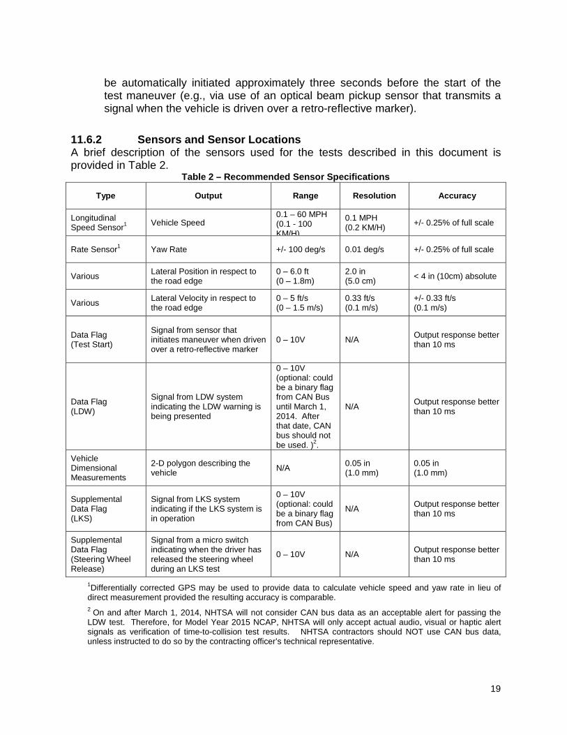
11.6.2 Sensors and Sensor Locations A brief description of the sensors used for the tests described in this document is provided in Table 2.
Table 2 – Recommended Sensor Specifications
Type Output Range Resolution Accuracy
Longitudinal Speed Sensor1 Vehicle Speed
0.1 – 60 MPH (0.1 - 100 KM/H)
0.1 MPH (0.2 KM/H) +/- 0.25% of full scale
Rate Sensor1 Yaw Rate +/- 100 deg/s 0.01 deg/s +/- 0.25% of full scale
Various Lateral Position in respect to the road edge
0 – 6.0 ft (0 – 1.8m)
2.0 in (5.0 cm) < 4 in (10cm) absolute
Various Lateral Velocity in respect to the road edge
0 – 5 ft/s (0 – 1.5 m/s)
0.33 ft/s (0.1 m/s)
+/- 0.33 ft/s (0.1 m/s)
Data Flag (Test Start)
Signal from sensor that initiates maneuver when driven over a retro-reflective marker
0 – 10V N/A Output response better than 10 ms
Data Flag (LDW)
Signal from LDW system indicating the LDW warning is being presented
0 – 10V (optional: could be a binary flag from CAN Bus until March 1, 2014. After that date, CAN bus should not be used. )2.
N/A Output response better than 10 ms
Vehicle Dimensional Measurements
2-D polygon describing the vehicle N/A 0.05 in
(1.0 mm) 0.05 in (1.0 mm)
Supplemental Data Flag (LKS)
Signal from LKS system indicating if the LKS system is in operation
0 – 10V (optional: could be a binary flag from CAN Bus)
N/A Output response better than 10 ms
Supplemental Data Flag (Steering Wheel Release)
Signal from a micro switch indicating when the driver has released the steering wheel during an LKS test
0 – 10V N/A Output response better than 10 ms
1Differentially corrected GPS may be used to provide data to calculate vehicle speed and yaw rate in lieu of direct measurement provided the resulting accuracy is comparable. 2 On and after March 1, 2014, NHTSA will not consider CAN bus data as an acceptable alert for passing the LDW test. Therefore, for Model Year 2015 NCAP, NHTSA will only accept actual audio, visual or haptic alert signals as verification of time-to-collision test results. NHTSA contractors should NOT use CAN bus data, unless instructed to do so by the contracting officer’s technical representative.
20
The microphone should be placed in close proximity to the source of the sound. A unidirectional accelerometer may be used to capture tactile alerts in the steering wheel and/or driver’s seat. A Light sensor should be able to capture changes in LDW icon alert if possible and rapid onset of a LDW icon. Location of the light sensor is vehicle dependent. All visual, audible, and haptic sensors should meet the range, resolution, and accuracy specifications stated above the LDW data flag. 11.6.2.1 Vehicle Speed
Vehicle speed shall be measured. Use of contact or non-contact based speed sensors is acceptable. Alternatively, GPS based sensors that have an update rate ≥ 100 Hz are acceptable. Sensor outputs are to be transmitted not only to the data acquisition system, but also to a dashboard display unit. This allows the driver to accurately monitor vehicle speed.
11.6.2.2 Yaw Rate
Yaw rate shall be measured. Corrected GPS may be used to provide data to calculate yaw rate in lieu of direct measurement, provided the resulting accuracy is comparable.
11.6.2.3 Lateral Position
Lateral position can be measured by several different sensors and/or measurement techniques provided they meet the range, resolution, and accuracy specifications provided in Table 2. The measurement should provide data indicating the lateral distance from the vehicle to the road edge line.2 Lateral distance is calculated by comparing the vehicles position (offset from the antenna position and the two dimensional polygon of the vehicle) to the road edge lines that have been surveyed.
Note: Others methods such as video based photometric measurements and inertial measurement system data that are supplemented with GPS may be acceptable [3], provided the Contractor can demonstrate the resulting measurements are at least as accurate as those produced via differentially corrected GPS data.
11.6.2.4 Lateral Velocity
Lateral velocity with respect to the road edge can be calculated using high precision, high update rate (10 Hz or greater), post-processed differential corrected GPS data. Using a static survey of a lane line, data from the vehicle is
2 Currently, NHTSA is using post-processed, differentially corrected global position system (GPS) data to objectively measure vehicle position relative to the lane line.
21
compared to the survey. Lateral distance and angle in regards to the lane line are calculated and then used to compute a lateral velocity using trigonometry [4].
Vlat = Vfwd * Sine Θ where: Vlat = Lateral velocity perpendicular to the vehicle in reference to the road edge. Vfwd = Forward velocity of the vehicle. Θ = Angle between the vehicle heading and the road edge.
Note: Others methods such as video based photometric measurements and inertial measurement system data that are supplemented with GPS may be acceptable [3], provided the Contractor can demonstrate the resulting measurements are at least as accurate as those produced via differentially corrected GPS data.
11.6.2.5 Test Start Data Flag
The Test Start Flag is a data channel that indicates the status of a signal used to initiate data collection. Use of an optical beam pickup sensor mounted on the center front of the vehicle be used to transmit this signal is recommended. In this application, the sensor provides a voltage output (open collector) with five (5) ms response time after crossing a retro-reflective line placed on the test surface.
11.6.2.6 LDW Activation Data Flag
The LDW system shall provide a warning to the driver by presenting an auditory alert, a visual alert, haptic vibration, haptic vehicle cue (for example, braking vibration , steering vibration, or seat vibration), or any combination thereof. (Steering torque or brake torque from a Lane Keeping Support system should not by itself be deemed a haptic signal, if a more definitive signal exists.) This output should be recorded and used as the measure of when the system warns. The output may be recorded from the vehicle communication network, or bus, directly from a discrete signal, and/or any other method that allows for a clear indication of when the warning was issued in relation to the other vehicle data being collected. At the direction of the COTR, use of a vehicle’s communication network or bus shall be performed in accordance with the vehicle manufacturer-provided specifications. Note that CAN data may be used for comparison, but will not be used for the Pass/Fail criteria. Prior to testing, the contractor should decide if the audible, visual, or haptic signal should be used for the Pass/Fail criteria.
22
As an option, a video channel(s) may be recorded with a time synchronized audio track detailing when an audible or visual alert was issued in respect to the video image. The National Institute of Standards and Technology (NIST) has successfully demonstrated such a system for assessing the system performance used in the Road Departure Collision Warning System (RDCWS) Field Operational Test (FOT) [3].
11.6.2.7 Data Flags For Supplemental LKS Evaluations 11.6.2.7.1 LKS Activation Data Flag
LKS interventions may rely on different hardware than that used by a vehicle’s LDW system, and may be initiated at a different time than the LDW alerts. For this reason, an additional data flag indicating when an LKS intervention occurs is necessary during conduction of the supplemental LKS tests. The output may be recorded from the CAN bus, directly from a discrete signal, and/or any other method that allows for a clear indication of when the warning was issued in relation to the other vehicle data being collected. At the direction of the COTR, use of a vehicle’s CAN bus shall be performed in accordance with the vehicle manufacturer-provided specifications.
11.6.2.7.2 Steering Wheel Release Data Flag
During conduct of the supplemental LKS tests, the driver is instructed to remove their hands from the steering wheel after the heading angle used to approach the lane line has been established. NHTSA has successfully used a micro switch configured to open when the driver has released the steering wheel for this purpose. When the driver returns their hands to the steering wheel at the conclusion of the test, the switch closes. Requiring the driver to remove their hands from the steering wheel before an LKS intervention objectively evaluates the ability for heading changes attributed to the system.
11.7 Alternate Mode of Operation
If the LDW system is operating in a failure mode (e.g., the system is not operational due to environmental, mechanical, or software-related reasons), the system shall suppress LDW alerts and notify the driver of the failure condition. An appropriate alert signal must be produced by the LDW system while the inside edge of the SV (represented as a two-dimensional polygon) is between -1.0 – 2.5 ft (-0.3 – 0.75 m) where a positive number represents a SV whose inside edge has not passed over the delimiting edge..
12.0 TEST EXECUTION AND TEST REQUIREMENTS If the Lane Departure Warning system provides a warning-time adjustment for
the driver, at least one setting must meet the criterion of the test procedure.

23
12.1 Static Instrumentation Calibration
A zero calibration should be performed for the GPS system in the SV and in the POV to align the lateral and longitudinal zero for the two GPS systems prior to testing. Align the centerline of the front-most location of the SV with the centerline of the rear-most location of the POV. An acceptable tolerance is ± 2.0 in (± 5 cm) of the actual zero. The GPS must be re-zeroed or recalibrated for any value outside of the acceptable tolerance. Records of the calibration must be provided with the test report.
12.1.2 LDW System Initialization
Before LDW system performance can be properly assessed, some vehicles require a brief period of initialization. During this time, diagnostics to verify functionality and sensor calibrations performed. If system initialization is required by a particular LDW system, the Office of Vehicle Safety Compliance (OVSC) will obtain the appropriate procedure from the respective vehicle manufacturer, and provide it to the Contractor. The Contractor shall perform any OVSC-provided initialization schedule prior to performing the tests specified below.
12.2 Test Maneuver Overview
To begin a test trial, the vehicle shall be driven in a straight line on a white-line-marked test track at a constant speed of 45 mph (72 km/h) for up to 200 feet if possible. As the test course entrance gates are approached, the driver shall manually steer the vehicle such that its heading is a straight line through the center of the gates (see Section 12.3 for the test course layout). The driver is not permitted to strike any cones used to define the test start gate. During the initialization and test phases, test drivers must refrain from using turn signals and from applying any sudden acceleration, sudden steering or sudden braking Use of cruise control is permitted as long as the vehicle speed requirements specified in S12.4.1 are satisfied. . Vehicles with non-adaptive cruise control shall not be permitted during the following tests. Non-adaptive cruise control could compound results. Any use of the turn signals, sudden acceleration, sudden steering or sudden braking will invalidate the test trial. In addition to cone strikes, vehicle speed and yaw rate data shall be used to identify bad trial data. Trials where speed and/or yaw rate was outside of the performance specification are invalid.
12.2.1 Land Departure Warning (LDW) Test Maneuver
24
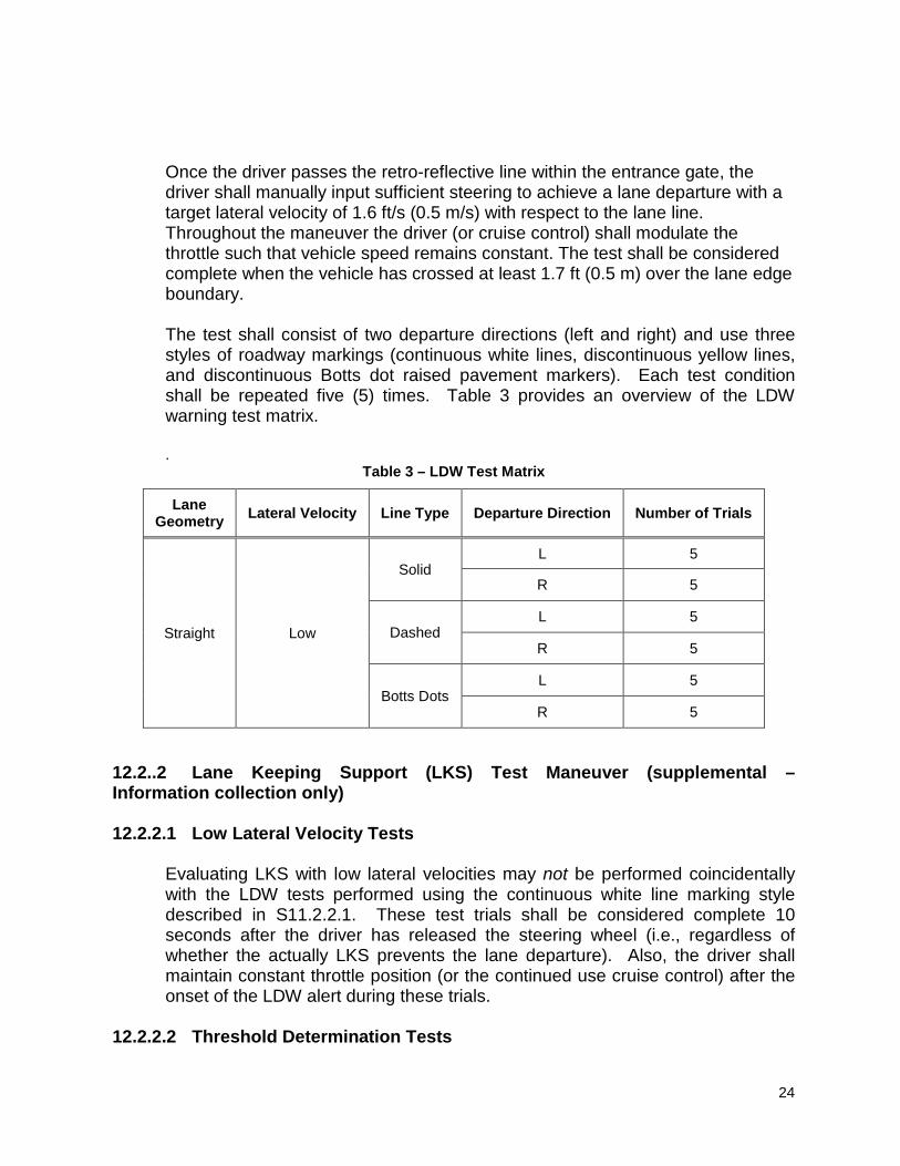
Once the driver passes the retro-reflective line within the entrance gate, the driver shall manually input sufficient steering to achieve a lane departure with a target lateral velocity of 1.6 ft/s (0.5 m/s) with respect to the lane line. Throughout the maneuver the driver (or cruise control) shall modulate the throttle such that vehicle speed remains constant. The test shall be considered complete when the vehicle has crossed at least 1.7 ft (0.5 m) over the lane edge boundary. The test shall consist of two departure directions (left and right) and use three styles of roadway markings (continuous white lines, discontinuous yellow lines, and discontinuous Botts dot raised pavement markers). Each test condition shall be repeated five (5) times. Table 3 provides an overview of the LDW warning test matrix. .
Table 3 – LDW Test Matrix
Lane Geometry Lateral Velocity Line Type Departure Direction Number of Trials
Straight Low
Solid L 5
R 5
Dashed L 5
R 5
Botts Dots L 5
R 5
12.2..2 Lane Keeping Support (LKS) Test Maneuver (supplemental – Information collection only) 12.2.2.1 Low Lateral Velocity Tests
Evaluating LKS with low lateral velocities may not be performed coincidentally with the LDW tests performed using the continuous white line marking style described in S11.2.2.1. These test trials shall be considered complete 10 seconds after the driver has released the steering wheel (i.e., regardless of whether the actually LKS prevents the lane departure). Also, the driver shall maintain constant throttle position (or the continued use cruise control) after the onset of the LDW alert during these trials.
12.2.2.2 Threshold Determination Tests

25
The second series of LKS tests are intended to quantify the systems’ ability to prevent lane departures. With one exception, the input conditions of these tests are identical to those used in S12.1.1, differing only in the magnitude of the lateral velocities used during the series. Using a series of ten (10) tests per direction of steer, the lateral velocities used during this test series are iteratively increased by 1.6 - 2.0 ft/s (0.5 - 0.6 m/s) to a magnitude where the LKS can no longer prevent a lane departure from occurring. In agreement with the throttle inputs specified in S12.2 , the driver shall maintain constant throttle position (or the continued use cruise control) after the onset of the LDW alert during these trials. In review, once the driver passes the retro-reflective line within the entrance gate, the driver shall manually input sufficient steering to achieve a lane departure with a target lateral velocity of 1.6 ft/s (0.5 m/s) with respect to the lane line. Throughout the maneuver the driver (or cruise control) shall modulate the throttle such that vehicle speed remains constant. The test shall be considered complete when the vehicle has crossed at least 1.7 ft (0.5 m) over the lane edge boundary. In subsequent tests, the target lateral velocity would be iteratively increased by 1.6 – 2 ft/s (0.5 – 0.6 m/s) Table 4 provides an overview of the LKS test matrix.
Table 4 – Supplemental LKS Test Matrix
Lane Geometry Lateral Velocity Line Type Departure Direction Number of Trials
Straight Low Solid L 5
R 5
Straight Iteratively Increased Solid
L 10
R 10
12.3 Straight Lane Departure Test Course
The straight lane departure test course shall be set up at a location that allows the test vehicle to easily reach the 45 mph (72 km/h) target speed, provides approximately 300 m (1000 ft) of area after the test starting point, and provides > 15 ft (5 m) of lateral runoff to ensure the vehicle may safely depart the lane. The test course shall have a start line constructed from retro-reflective tape, 15 in (38 cm) deep, and wide enough so that the vehicle will pass over it when the center of the vehicle is near the center of the lane. The start gate is defined by four non-reflective, low-contrast color and low-

26
contrast construction pylons that are spaced 8 in (20 cm) further than the width of the vehicle divided by two (2). The pylons should be spaced 20 ft (6 m) apart longitudinally from the starting point. The pylons should be placed so that the center of the start gate is 6 ft (1.8 m) from the center of the lane line to be departed. The location of each pylon should be marked, and the position checked between each run. If one or more of the pylons is struck, the pylon must be placed back in the correct position, and the test should be rerun. Figure 3 illustrates the test scenario for a left departure from a continuous white line. This test course configuration shall be replicated for the trials using dashed yellow lines and continuous raised pavement markers (i.e., in lieu of the solid white line). The vehicle shall be driven on the right side of the lane line to evaluate left-side lane departure warning performance, and on the left side of the lane line for the right-side lane departure tests. Note: To assist the driver in establishing the correct lane position before reaching the start gate, an additional pylon-delimited gate may be placed 246 ft (75 m) before the test start point, positioned so that the center of the gate is 6 ft (1.8 m) from the center of the lane line to be departed. These pylons should also be non-reflective, low-contrast color and low-contrast construction.
12.4 Test Validity Conditions 12.4.1 Vehicle Speed
All LDW tests shall be conducted at 45 mph (72 km/h). Test speed shall be monitored and a test will be considered valid if the test speed remains within 45 ± 1.2 mph (72 ± 2 km/h).. The speed must remain within this window from the start of the test until any part of the vehicle, as defined by the two dimensional geometry described in Section 8.3.f has crossed a lane line by 1.7 ft (0.5 m) or more.
12.4.2 Lateral Velocity 12.4.2.1 During LDW Evaluation
All LDW tests shall be conducted under a low lateral velocity condition. In the context of this test procedure, low lateral velocity is defined as a lane departure with a lateral velocity, measured with respect to the lane line, of 0.3 to 2.0 ft/s (0.1 to 0.6 m/s) with a target later velocity of 1.6 ft/s (0.5 m/s). To assist the test driver in being able to efficiently establish the target lateral velocity, pylons may be positioned in the manner shown in Figure 4. Note: Striking the pylons used to assist the driver with establishing the target lateral velocity with test vehicle does not deem a test non-valid.

27
12.4.2.2 During LKS Evaluation 12.4.2.2.1 Low Lateral Velocity LKS Evaluation
The lateral velocities used when approaching the lane line during the low lateral velocity LKS tests are identical to those described in the S12.3.2.1 LDW specification.
12.42.2.2 LKS Threshold Determination Evaluation
The lateral velocities used when approaching the lane line during the LKS threshold determination tests, measured with respect to the lane line, nominally range from 2.0 ft/s (0.6 m/s) to a magnitude where the LKS can no longer prevent a lane departure from occurring.
12.4.3 Yaw Rate 12.4.3.1 During LDW Evaluation
At no time during the lane departure maneuver, from the time the vehicle passes through the final course entrance gate to the instant the vehicle has crossed a lane line by 1.7 ft (0.5 m), shall the vehicle’s yaw rate exceed 1.0 deg/sec.
12.4.3.2 During LKS Evaluation
12.4.3.2.1 Low Lateral Velocity LKS Evaluation
The yaw rate restrictions for LKS tests performed with low lateral velocities are
Figure 4. Recommended pylon spacing to facilitate valid lateral velicities

28
identical to those described in the S12.3.3.1 LDW specification. 12.4.3.2.2 LKS Threshold Determination Evaluation
The yaw rates needed to quickly establish the inherently higher lateral velocities used in LKS threshold determination tests should be as low as possible. Use of excessively high yaw rates may confound the driver’s ability to realize the LKS functionality this test procedure seeks to evaluate. Steering inputs resulting in high yaw rates may cause LKS interventions to be suppressed if the systems interprets the driver’s inputs as a deliberate lane change maneuver attempt.
125 LDW Pass or Fail Criteria
The test outputs from each trial shall be used to produce a pass or fail measure. The measure will be based on whether the LDW issues an appropriate alert during the maneuver. In the context of this test procedure, a lane departure is said to occur when any part of the two dimensional polygon used to represent the test vehicle3 breaches the inboard4 lane line edge. In the case of tests performed in this procedure, the outside front corner of the polygon will cross the line edge first. In other words, if the vehicle departs its lane to the left, the left front corner of the polygon would first breach the lane line edge. For an individual trial to successfully pass the test,
1. Test speed and yaw rate validity conditions must be satisfied. 2. The lateral velocity of the vehicle at the time of the LDW alert must be
between 0.3 to 2.0 ft/s(0.1 to 0.6 m/s). 3. The LDW alert must not occur when the lateral position of the vehicle is
greater than +2.5 ft (+0.75 m) from the lane line edge. Vehicles in-lane are given positive values.
4. The LDW alert must occur before the lane departure exceeds – 1.0 ft (-0.3 m).
In summary, a valid trial is considered a failure if distance between the inside edge of the polygon to the lane line at the time of the LDW warning is outside -1.0 – 2.5 ft (-0.3 – 0.75 m),where a negative number represents post-line position, or if no warning is issued. To be awarded an overall passing grade, the LDW system must satisfy the pass criteria for 3 of 5 individual trials for each combination of departure direction and lane line type (60 percent), and pass 20 of the 30 trials overall (66 percent). If
3 The two-dimensional polygon is defined by the axles in the X-direction (fore-aft), the outer edge of the tire in the y-direction (lateral), and the ground in the z-direction (vertical). 4 The inboard side of the line is defined as that which is closest to the vehicle before the departure occurs.

29
more than 5 trials are deemed valid, the Pass/Fail criteria must be met for 3 of the first 5 valid trials.
12.6 LKS Performance Assessment (for information collection only)
This test procedure does not contain LKS performance requirements. As previously described in S2.0, the data output from conducting the LKS tests described in this test procedure are intended to supplement the LDW test results, and will be used for informative purposes only. To document LKS system performance, the Contractor shall:
1. Report how many LKS tests performed with lateral velocities between 0.3 ft/s to 2.0 ft/s (0.1 to 0.6 m/s) were able to prevent a lane departure. For the tests where a departure was prevented, the lateral distance from the corner of the vehicle closest to the lane line shall be reported.
2. Report the lateral velocities used to determine the LKS performance threshold and whether a lane departure was prevented during each test trial. The LKS performance threshold is defined as the largest lateral velocity in which a lane departure is prevented. For the tests where a departure was prevented, the lateral distance from the corner of the vehicle closest to the lane line shall be reported.
3. If the LKS tests are performed using a lane delineated with two lines, report the occurrence of any secondary lane departures. A secondary lane departure results from an LKS-induced heading correction away from the initial lane departure (i.e., if a test was performed with an initial departure to the right, a secondary departure will occur when the vehicle crosses a lane line to the vehicle’s left.
13.0 POST TEST REQUIREMENTS 13.1 Vehicle Data and Test Documentation
The Contractor shall collect all data necessary to complete the final test report data sheets and provide details of any problem areas.
13.2 Post Test Vehicle Inspection. The Contractor shall inspect the test vehicle after all testing is completed. Any vehicle modifications or damage shall be restored to the as-delivered condition or the vehicle shall be declared “totaled” and shall be disposed of as a totally destroyed vehicle. Disposition of the vehicle shall be determined by the Government. Any damage incurred to the vehicle during the actual tests, except

30
damage caused by negligence of the Contractor, shall be the responsibility of the Government.
14.0 REPORTS 14.1 Monthly Status Reports
The Contractor shall submit a monthly Test Status Report and a Vehicle or Equipment Status Report to the COTR (both reports shown in this section). The Vehicle Status Report shall be submitted until all vehicles or items of equipment are disposed of.
14.2 Test Anomalies
In the event of an apparent test failure, a post-test calibration check of critically sensitive test equipment and instrumentation may be required for verification of accuracy. The necessity for the calibration shall be at the COTR's discretion and shall be performed without additional costs to the OCAS.
14.3 Final Test Report 14.3.1 Copies
The Contractor shall provide the OCAS with one (1) CD per test. Two items shall be included on each CD: (1) a JPG of the vehicle in its test mode, taken with a resolution of at least 800 x 600 pixels, and (2) test video footage. In addition to the CD, the Contractor shall provide the OCAS with one paper copy of each Final Test Report. The above documentation shall be submitted to the COTR according to the schedule indicated in Section 6.
Contractors are required to submit one color copy of each Final Test Report in draft form. DO NOT stamp preliminary or draft on this report. The COTR will review the draft report and notify the laboratory of any corrections that are required. If we agree to make changes to the test report, mail the appropriate (the changed) pages to us. We will insert the new pages into the preliminary test report. At the end, we will accept the preliminary test report with the inserted pages as the final test report.
14.3.2 Requirements
The Final Test Report, associated documentation (including photographs) is relied upon as the chronicle of the test. The Final Test Report will be released to the public domain after review and acceptance by the COTR. For these
31
reasons, each final report must be a complete document capable of standing by itself.
The Contractor should use detailed descriptions of all test events. Any events that are not directly associated with the test program, but are of technical interest should also be included. The Contractor should include as much detail as possible in the report. Instructions for the preparation of the first three pages of the final test report are provided below for the purpose of standardization.
14.3.3 First Three Pages
Front Cover - - A heavy paperback cover (or transparency) shall be provided for the protection of the final report. The information required on the cover is as follows: (A) Final Report Number such as OCAS-ABC-0X-001
where - - OCAS is the Office of Crash Avoidance Standards ABC are the initials for the laboratory 0X is the Fiscal Year of the test program 001 is the Group Number (00 1 for the 1st test, 002 for the 2nd test, 003for the 3rd test, etc.)
(B) Final Report Title And Subtitle such as
Lane Departure Warning Confirmation Test (and Lane Keeping Support Test, if applicable) **************************************** World Motors Corporation 200X XYZ 4-door sedan NHTSA No. CX0401
(C) Contractor's Name and Address such as
XYZ TESTING LABORATORIES, INC. 4335 West Dearborn Street Detroit, Michigan 48090
NOTE: DOT SYMBOL WILL BE PLACED BETWEEN ITEMS (C) AND (D)
(D) Date of Final Report completion
(E) The words “FINAL REPORT” (F) The sponsoring agency's name and address as follows
U. S. DEPARTMENT OF TRANSPORTATION National Highway Traffic Safety Administration Office of Crash Avoidance Standards Mail Code: NVS-120 1200 New Jersey Avenue SE, Room W43-478 Washington, DC 20590
32
First Page After Front Cover - - A disclaimer statement and an acceptance signature block for the COTR shall be provided as follows:
This publication is distributed by the U.S. Department of Transportation, National Highway Traffic Safety Administration, in the interest of information exchange. The opinions, findings and conclusions expressed in this publication are those of the author(s) and not necessarily those of the Department of Transportation or the National Highway Traffic Safety Administration. The United States Government assumes no liability for its contents or use thereof. If trade or manufacturers' names or products are mentioned, it is only because they are considered essential to the object of the publication and should not be construed as an endorsement. The United States Government does not endorse products or manufacturers.
Prepared By: _____________________________________
Approved By: _____________________________________
Approval Date: _____________________________________
Second Page After Front Cover - - A completed Technical Report Documentation Page (Form DOT F1700.7) shall be completed for those items that are applicable with the other spaces left blank. Sample data for the applicable block numbers of the title page follows.
Block No. 1 - - REPORT NUMBER
OCAS-ABC-0X-001
Block No. 2 - - GOVERNMENT ACCESSION NUMBER
Leave blank
Block No. 3 - - RECIPIENT'S CATALOG NUMBER
Leave blank
Block No. 4 - - TITLE AND SUBTITLE
Final Report of OCAS Testing of a 200X World XYZ Deluxe 4-door sedan NHTSA No. CX0401
Block No. 5 - - REPORT DATE
March 1, 200X
Block No. 6 - - PERFORMING ORGANIZATION CODE

33
ABC Block No. 7 - - AUTHOR(S)
John Smith, Project Manager Bill Doe, Project Engineer
Block No. 8 - - PERFORMING ORGANIZATION REPORT NUMBER
ABC-DOT-XXX-001
Block No. 9 - - PERFORMING ORGANIZATION NAME AND ADDRESS
ABC Laboratories 405 Main Street Detroit, Ml 48070
Block No. 10 - - WORK UNIT NUMBER
Leave blank
Block No. 11 - - CONTRACTOR GRANT NUMBER
DTNH22-0X-D-1 2345
Block No. 12 - - SPONSORING AGENCY NAME AND ADDRESS
U. S. DEPARTMENT OF TRANSPORTATION National Highway Traffic Safety Administration Office of Crash Avoidance Standards Mail Code: NVS-120 1200 New Jersey Avenue SE, Room W43-478 Washington, DC 20590
Block No. 13 - - TYPE OF REPORT AND PERIOD COVERED
Final Test Report XXX to XXX, 200X
Block No. 14 - - SPONSORING AGENCY CODE
NVS-120
Block No. 15 - - SUPPLEMENTARY NOTES
Leave blank
Block No. 16 - - ABSTRACT
These tests were conducted on the subject 20XX World XYZ 4-door sedan in accordance with the specifications of the Office of Crash Avoidance Standards Test Procedure No. TP-OCAS-XX for the determination of vehicle lane departure warning performance.
Block No. 17 - - KEY WORDS

34
Lane Departure Warning test
Block No. 18 - - DISTRIBUTION STATEMENT
Copies of this report are available from the following:
NHTSA Technical Reference Division National Highway Traffic Safety Administration 1200 New Jersey Avenue SE Washington, DC 20590
Block No. 19 - - SECURITY CLASSIFICATION OF REPORT
Unclassified
Block No. 20 - - SECURITY CLASSIFICATION OF PAGE
Unclassified
Block No. 21 - - NO. OF PAGES
Add appropriate number
Block No. 22 - - PRICE
Leave blank 14.3.4 Table of Contents ...................................................................................................... PAGE NO.
Sample Test Report Table of Contents: A. Section 1 — Purpose and Summary of the Test B. Section 2 — Vehicle Information/Data Sheets C. Section 3 — Photographs D. Section 4 — Vehicle data traces. E. Section 5 — Test Equipment and Instrumentation Calibration
14.3.5 Sample Test Report Information
PURPOSE AND SUMMARY OF TEST
PURPOSE
This test is part of the a test program sponsored by the National Highway Traffic Safety Administration
(NHTSA) under Contract No.___________. The purpose of this test was to obtain vehicle crash
avoidance performance data for lane departure warning.

35
SUMMARY
DATA SHEET NO. DESCRIPTION
1. Test Summary
2. General Test and Vehicle Parameter Data
3. Post test Data
4. Test Vehicle Information
5. Vehicle Measurements
36
15.0 DATA SHEETS
DATA SHEET NO. 1
TEST SUMMARY
Vehicle NHTSA No.:
Test Date: Time: Temperature: oC
Vehicle Make/Model/Body Style:
Vehicle Test Weight: kg Lane Departure Warning Confirmed
Lane Departure Warning setting (Provided by the Manufacturer to the COTR) ____________

37
DATA SHEET NO. 2
GENERAL TEST AND VEHICLE PARAMETER DATA TEST VEHICLE INFORMATION:
Year/Make/Model/Body Style:
NHTSA No.: ; VIN: ; Color:
Engine Data: Cylinders; CID; Liters; cc
Transmission Data: speeds; Manual; Automatic; Overdrive
Final Drive: Rear Wheel Drive; Front Wheel Drive; Four Wheel Drive
Date Received: ; Odometer Reading Km or mi
LDW Type:
DATA FROM VEHICLE'S CERTIFICATION LABEL: Vehicle Manufactured by:
Date of Manufacture
GVWR: kg; GAWR: kg FRONT; kg REAR DATA FROM TIRE OR TIRE PLACARD: Tire Pressure with Maximum Capacity Vehicle Load: kpa FRONT
kpa REAR
Load Index & Speed Symbol:
Recommended Tire Size:
Recommended Cold Tire Pressure*: kpa FRONT; kpa REAR
Tire Grades: ___________ Treadwear; Temperature; ______________ Traction
Size of Tires on Test Vehicle: ; Manufacturer: *Tire pressure used for test
FUEL SYSTEM DATA : Fuel System Capacity From Owner's Manual = liters Test Volume Range (75 % to 100% of Usable Capacity) = Gage Reading

38
DATA SHEET NO. 3
PHOTOGRAPHS

39
16.0 REFERENCES
1. Federal Highway Administration. Manual on Uniform Traffic Control Devices. http://mutcd.fhwa.dot.gov/index.htm.
2. Szabo, S., Norcross, R., Recommendations for Objective Test Procedures for Road
Departure Crash Warning Systems. NISTIR 7288, February 2006. 3. Szabo, S., Norcross, R., An Independent Measurement System for Performance
Evaluation of Road Departure Crash Warning Systems. NISTIR 7287. January 2006.
4. Burgett, A., Ranganathan, R., Srinivasan, G., Development Of Objective Tests For
Evaluation Lane-Keeping/Road Departure Driver Assistance Systems, Proceedings from ESV 2007. Paper Number 07-0155.