model 755a* - incremental shaft encoderencoder.com/literature/datasheet-755a-shaft.pdfmodel 755a* -...
TRANSCRIPT
1-800-366-5412 • www.encoder.com • [email protected] Rev. 04/10/18
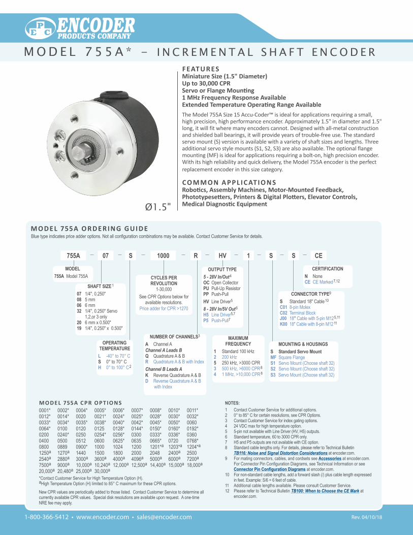
F eat u r esMiniature size (1.5" Diameter)up to 30,000 CPr Servo or Flange Mounting1 MHz Frequency response availableExtended Temperature Operating Range AvailableThe Model 755A Size 15 Accu-Coder™ is ideal for applications requiring a small, high precision, high performance encoder. Approximately 1.5" in diameter and 1.5" long, it will fit where many encoders cannot. Designed with all-metal construction and shielded ball bearings, it will provide years of trouble-free use. The standard servo mount (S) version is available with a variety of shaft sizes and lengths. Three additional servo style mounts (S1, S2, S3) are also available. The optional flange mounting (MF) is ideal for applications requiring a bolt-on, high precision encoder. With its high reliability and quick delivery, the Model 755A encoder is the perfect replacement encoder in this size category.
Co M M o n a P P l i C at i o n sRobotics, Assembly Machines, Motor-Mounted Feedback, Phototypesetters, Printers & Digital Plotters, Elevator Controls, Medical Diagnostic Equipment
M o D e l 755a o r D e r i n g g u i D eBlue type indicates price adder options. Not all configuration combinations may be available. Contact Customer Service for details.
NOTES:1 Contact Customer Service for additional options.2 0° to 85° C for certain resolutions, see CPR Options.3 Contact Customer Service for index gating options.4 24 VDC max for high temperature option.5 5-pin not available with Line Driver (HV, H5) outputs.6 Standard temperature, 60 to 3000 CPR only.7 H5 and P5 outputs are not available with CE option.8 Standard cable lengths only. For details, please refer to Technical Bulletin
TB116: Noise and Signal Distortion Considerations at encoder.com.9 For mating connectors, cables, and cordsets see Accessories at encoder.com.
For Connector Pin Configuration Diagrams, see Technical Information or see Connector Pin Configuration Diagrams at encoder.com.
10 For non-standard cable lengths, add a forward slash (/) plus cable length expressed in feet. Example: S/6 = 6 feet of cable.
11 Additional cable lengths available. Please consult Customer Service.12 Please refer to Technical Bulletin TB100: When to Choose the CE Mark at
encoder.com.
M o D e l 755a C P r o P t i o n s0001* 0002* 0004* 0005* 0006* 0007* 0008* 0010* 0011* 0012* 0014* 0020 0021* 0024* 0025* 0028* 0030* 0032* 0033* 0034* 0035* 0038* 0040* 0042* 0045* 0050* 0060 0064* 0100 0120 0125 0128* 0144* 0150* 0160* 0192* 0200 0240* 0250 0254* 0256* 0300 0333* 0336* 0360 0400 0500 0512 0600 0625* 0635 0665* 0720 0768* 0800 0889 0900* 1000 1024 1200 1201*a 1203*a 1204*a 1250a 1270a 1440 1500 1800 2000 2048 2400a 2500 2540a 2880a 3000a 3600a 4000a 4096a 5000a 6000a 7200a 7500a 9000a 10,000a 10,240a 12,000a 12,500a 14,400a 15,000a 18,000a 20,000a 20,480a 25,000a 30,000a
*Contact Customer Service for High Temperature Option (H).aHigh Temperature Option (H) limited to 85° C maximum for these CPR options.
New CPR values are periodically added to those listed. Contact Customer Service to determine all currently available CPR values. Special disk resolutions are available upon request. A one-time NRE fee may apply.
CE1HVR1000 SS07 S
CYCLES PER REVOLUTION
1-30,000See CPR Options below for
available resolutions.Price adder for CPR >1270
MODEL755A Model 755A
MAXIMUMFREQUENCY
1 Standard 100 kHz2 200 kHz5 250 kHz, >3000 CPR3 500 kHz, >6000 CPR8
4 1 MHz, >10,000 CPR8
MOUNTING & HOUSINGSS Standard Servo MountMF Square FlangeS1 Servo Mount (Choose shaft 32)S2 Servo Mount (Choose shaft 32)S3 Servo Mount (Choose shaft 32)
CERTIFICATIONN NoneCE CE Marked7,12
CONNECTOR TYPE9
S Standard 18" Cable10
C01 8-pin MolexC02 Terminal Blockj00 18" Cable with 5-pin M125,11
K00 18" Cable with 8-pin M1211
OPERATINGTEMPERATURE
L -40° to 70° CS 0° to 70° C H 0° to 100° C2
SHAFT SIZE1
07 1/4", 0.250"08 5 mm06 6 mm32 1/4", 0.250" Servo 1,2,or 3 only20 6 mm x 0.500"19 1/4", 0.250" x 0.500"
NUMBER OF CHANNELS3
A Channel AChannel A Leads BQ Quadrature A & BR Quadrature A & B with Index Channel B Leads AK Reverse Quadrature A & BD Reverse Quadrature A & B
with Index
OUTPUT TYPE 5 - 28V In/Out4
OC Open CollectorPU Pull-Up ResistorPP Push-PullHV Line Driver58 - 28V In/5V Out6
H5 Line Driver5,7
P5 Push-Pull7
755A
Ø1.5"
M o d e l 7 5 5 A * - i n c r e M e n t A l s h A f t e n c o d e r
1-800-366-5412 • www.encoder.com • [email protected]
Function
Gland Cable†
Wire Color
Term. Block
8-pin Molex
5-pin M12**
8-pinM12**
Com Black 7 2 3 7+VDC White 8 1 1 2
A Brown 1 8 4 1A' Yellow 2 7 -- 3B Red 3 4 2 4B' Green 4 3 -- 5Z Orange 6 6 5 6Z' Blue 5 5 -- 8
Shield Bare* -- -- -- --*CE Option: Cable shield (bare wire) is connected to internal case.
†Standard cable is 24 AWG conductors with foil and braid shield.**CE Option: Use cable cordset with shield connected to M12 connector coupling nut.
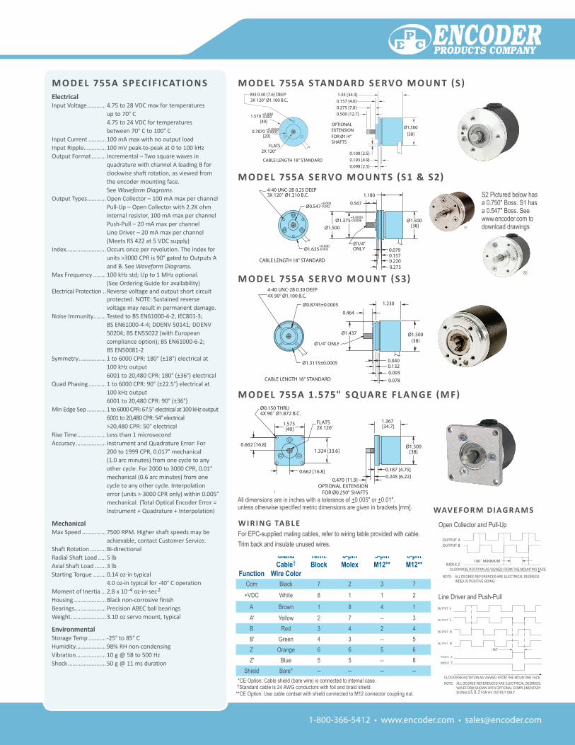
M o D e l 755a s P eC i F i C at i o n selectricalInput Voltage ............4.75 to 28 VDC max for temperatures
up to 70° C 4.75 to 24 VDC for temperatures between 70° C to 100° C
Input Current ...........100 mA max with no output loadInput Ripple ..............100 mV peak-to-peak at 0 to 100 kHzOutput Format ......... Incremental – Two square waves in
quadrature with channel A leading B for clockwise shaft rotation, as viewed from the encoder mounting face. See Waveform Diagrams.
Output Types............Open Collector – 100 mA max per channel Pull-Up – Open Collector with 2.2K ohm internal resistor, 100 mA max per channel Push-Pull – 20 mA max per channel Line Driver – 20 mA max per channel (Meets RS 422 at 5 VDC supply)
Index .........................Occurs once per revolution. The index for units >3000 CPR is 90° gated to Outputs A and B. See Waveform Diagrams.
Max Frequency ........100 kHz std; Up to 1 MHz optional. (See Ordering Guide for availability)
Electrical Protection ..Reverse voltage and output short circuit protected. NOTE: Sustained reverse voltage may result in permanent damage.
Noise Immunity........Tested to BS EN61000-4-2; IEC801-3; BS EN61000-4-4; DDENV 50141; DDENV 50204; BS EN55022 (with European compliance option); BS EN61000-6-2; BS EN50081-2
Symmetry .................1 to 6000 CPR: 180° (±18°) electrical at 100 kHz output 6001 to 20,480 CPR: 180° (±36°) electrical
Quad Phasing ...........1 to 6000 CPR: 90° (±22.5°) electrical at 100 kHz output 6001 to 20,480 CPR: 90° (±36°)
Min Edge Sep ............1 to 6000 CPR: 67.5° electrical at 100 kHz output 6001 to 20,480 CPR: 54° electrical >20,480 CPR: 50° electrical
Rise Time .................. Less than 1 microsecondAccuracy ................... Instrument and Quadrature Error: For
200 to 1999 CPR, 0.017° mechanical (1.0 arc minutes) from one cycle to any other cycle. For 2000 to 3000 CPR, 0.01° mechanical (0.6 arc minutes) from one cycle to any other cycle. Interpolation error (units > 3000 CPR only) within 0.005° mechanical. (Total Optical Encoder Error = Instrument + Quadrature + Interpolation)
Mechanical Max Speed ...............7500 RPM. Higher shaft speeds may be
achievable, contact Customer Service.Shaft Rotation ..........Bi-directionalRadial Shaft Load .....5 lbAxial Shaft Load .......3 lbStarting Torque ........0.14 oz-in typical
4.0 oz-in typical for -40° C operationMoment of Inertia ...2.8 x 10-4 oz-in-sec2
Housing ....................Black non-corrosive finishBearings....................Precision ABEC ball bearingsWeight ......................3.10 oz servo mount, typical
environmental Storage Temp ........... -25° to 85° CHumidity...................98% RH non-condensingVibration...................10 g @ 58 to 500 HzShock ........................50 g @ 11 ms duration
M O D E l 755A 1.575" S q uA R E F l A n g E (M F)
M O D E l 755A S E RvO M O u n T (S3)
All dimensions are in inches with a tolerance of +0.005" or +0.01".unless otherwise specified metric dimensions are given in brackets [mm].
S1
M O D E l 755A S E RvO M O u n T S (S1 & S2)
M O D E l 755A STA n DA R D S E RvO M O u n T (S)
S2
S2 Pictured below has a 0.750" Boss. S1 has a 0.547" Boss. See www.encoder.com to download drawings
Line Driver and Push-Pull
Wav e Fo r M D i ag r a M s
Open Collector and Pull-Up
NOTE: ALL DEGREE REFERENCES ARE ELECTRICAL DEGREES. INDEX IS POSITIVE GOING.
11B NONE
C ECO #01006
REVISIONSLTR DESCRIPTION DATE
OFSHEET
DATE NAME AND TITLE
DWG NUMBER
DWG SIZE SCALE
EP
INITIAL
QC
CK
DR
DECIMAL
-
DECIMAL
+-
ANGULAR
+
TOLERANCE
ENG.1°-+MFGPART NUMBER
NEXT ASSEMBLY
ISSUE DATE
PREV ASSEMBLY
C ENCODER PRODUCTS COMPANY
REV.
55A-ser F
GDB 5/25/00.005
.01
MODEL 755A SERVO MOUNT (S)
D ECO #01185
THIRD ANGLE PROJECTION
B ECO #00646
CABLE LENGTH 18" STANDARD
E ECO #01965 GMA 04/07/04
0.193 [4.9]
OPTIONALEXTENSION
FOR Ø1/4"SHAFTS
0.500 [12.7]
FLATS 2X 120° 0.100 [2.5]
1.35 [34.3]
0.098 [2.5]
0.275 [7.0]
0.157 [4.0]
Ø1.500
[38]
M3 0.30 [7.6] DEEP 3X 120° Ø1.100 B.C.
55A-ser
�0.7870 +0.0000-0.0005
[20]
�1.570 +0.000-0.002
[40]
F ECO #06367 JP 05/16/12
B ECO #01185
C ECO #01965 GMA 04/06/04
A ECO #00833
C
GDB
B NONE
55A-SM1 C
MODEL 755A SERVO MOUNT (S1)
EP
THIRD ANGLE PROJECTION
11 OFSHEET
NAME AND TITLE
DWG NUMBER
DWG SIZE SCALE
DECIMAL
DECIMAL
-
ANGULAR
+
TOLERANCE
.1°+PART NUMBER
NEXT ASSEMBLY
ISSUE DATE
PREV ASSEMBLY
ENCODER PRODUCTS COMPANY
REV.
.005
.01 QC
CK
DR-
+
PRJ ENG-
MFG
DATEINITIAL
REVISIONSLTR DESCRIPTION DATE
NOTE: ALL DEGREE REFERENCES ARE ELECTRICAL DEGREES. WAVEFORM SHOWN WITH OPTIONAL COMPLEMENTARY SIGNALS A, B, Z FOR HV OUTPUT ONLY.
W i r i n g ta b l eFor EPC-supplied mating cables, refer to wiring table provided with cable.Trim back and insulate unused wires.
CLOCKWISE ROTATION AS VIEWED FROM THE MOUNTING FACE
CLOCKWISE ROTATION AS VIEWED FROM THE MOUNTING FACE