model 464 electronic pump control unit user guide - solinst
TRANSCRIPT

Model 464 Mk3 Electronic Pump Control Unit User Guide
January 10, 2017 #109652 Rev. B

Model 464 Electronic Control Unit User Guide - Contents
1.0 Introduction 11.1 Operating Principles 1
1.2 Model 464 Electronic Control Unit Specifications 1
1.3 Control Panel 2
1.4 LCD Display 2
2.0 Control Unit Operation 32.1 Start Up 3
2.1.1 Main Menu 3
2.2 LCD Contrast 4
2.3 About 4
2.4 Preset Flow Rates 4
2.5 User Flow Rates 5
2.5.1 Saved Settings 5
Edit Settings 6
Delete Settings 6
2.5.2 Create Setting 7
2.6 Automatic Drive/Vent Cycles 7
2.7 Manual Drive/Vent Cycles 8
2.8 Battery Replacement 8
3.0 Pumping Instructions 93.1 Preparation 9
3.2 Pumping Set Up 9
3.3 Pump Optimization 10
Bladder Pumps 10
Double Valve Pumps 10
4.0 Accessories 11
5.0 Maintenance 12
6.0 Storage 13

Model 464 Electronic Pump Control Unit User Guide
Page 1
1.0 Introduction
1.1 Operating Principles
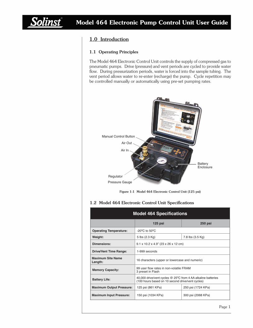
The Model 464 Electronic Control Unit controls the supply of compressed gas to pneumatic pumps. Drive (pressure) and vent periods are cycled to provide water flow. During pressurization periods, water is forced into the sample tubing. The vent period allows water to re-enter (recharge) the pump. Cycle repetition may be controlled manually or automatically using pre-set pumping rates.
1.2 Model 464 Electronic Control Unit Specifications
Figure 1-1 Model 464 Electronic Control Unit (125 psi)
Manual Control Button
Battery Enclosure
RegulatorPressure Gauge
Air Out
Air In
Model 464 Specifications
125 psi 250 psi
Operating Temperature: -20ºC to 50ºC
Weight: 5 lbs (2.3 Kg) 7.8 lbs (3.5 Kg)
Dimensions: 9.1 x 10.2 x 4.9” (23 x 26 x 12 cm)
Drive/Vent Time Range: 1-999 seconds
Maximum Site Name Length: 16 characters (upper or lowercase and numeric)
Memory Capacity: 99 user flow rates in non-volatile FRAM 3 preset in Flash
Battery Life: 40,000 drive/vent cycles @ 25ºC from 4 AA alkaline batteries (100 hours based on 10 second drive/vent cycles)
Maximum Output Pressure: 125 psi (861 KPa) 250 psi (1724 KPa)
Maximum Input Pressure: 150 psi (1034 KPa) 300 psi (2068 KPa)

Model 464 Electronic Pump Control Unit User Guide
Page 2
User Flow RatesLCD ContrastAbout
ECU 464-125 Main
Preset Flow Rates
4:59 Min 99% Timer: indicates the amount of time remaining before the Control Unit automatically turns off. The Control Unit will automatically turn off after 5 minutes of being idle.
User Flow RatesLCD ContrastAbout
ECU 464-125 Main
Preset Flow Rates
4:59 Min 99% Battery icon: represents the battery life remaining. Battery life is also numerically displayed as a percentage to the left of the icon. The icon will flash when the battery percentage is 0.
99
User Flow Rates
LCD Contrast
About
ECU 464 Main Menu
Preset Flow Rates
99
User Flow Rates
LCD Contrast
About
ECU 464 Main Menu
Preset Flow Rates
Arrows: left pointing arrow indicates there is at least one menu that can be accessed using the left cursor key. Right pointing arrow indicates a sub-menu exists for the active menu item, and can be accessed using the right cursor key or OK button (moves to next item).
Figure 1-2 Electronic Control Unit LCD Display
User Flow RatesLCD ContrastAbout
ECU 464-125 Main
Preset Flow Rates
4:59 Min 99%
OK OK button: selects a highlighted menu item (also toggles between lower and uppercase letters and pressure units). Press and hold for at least 3 seconds to turn the Control Unit off. (However, this will not work in the Contrast Menu, you can only use the left cursor key to exit the menu, and the plus/minus keys to adjust the contrast.)
Cursor keys: navigate through the menus and menu items.
Plus/Minus keys: cycle through numbers and letters when editing or creating new flow rates. Increase/decrease LCD display contrast. (Hold down to scroll quickly through values).
Manual Control Valve: allows manual operation of the Control Unit. When pushed the solenoid opens. See Page 8.
Air In: connection for the supply line from the compressed gas supply source. (In-line filter is not required.)
Air Out: connection for the drive line from the pump.
Regulator: sets the pumping pressure. Turn clockwise to increase the pumping pressure and counter-clockwise to decrease pressure.
Pressure Gauge: displays the pumping pressure.
Battery Enclosure: houses four (4) AA alkaline batteries.
1.4 LCD Display
1.3 Control Panel NOTE
Pressing any key will turn the Control Unit on (except Manual Control button).
NOTEThe Control Unit will turn off automatically after 5 minutes of being idle, provided that cycling is not active.
NOTEBattery Life is 40,000 drive/vent cycles or 100 hours at 10 second drive/vent cycles.
Model 464 Electronic Pump Control Unit User Guide
Page 3
2.0 Control Unit Operation
2.1 Start Up
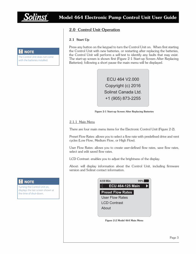
Press any button on the keypad to turn the Control Unit on. When first starting the Control Unit with new batteries, or restarting after replacing the batteries, the Control Unit will perform a self-test to identify any faults that may exist. The start-up screen is shown first (Figure 2-1 Start-up Screen After Replacing Batteries); following a short pause the main menu will be displayed.
Figure 2-1 Start-up Screen After Replacing Batteries
ECU 464 V2.000Copyright (c) 2016Solinst Canada Ltd.+1 (905) 873-2255
2.1.1 Main Menu
There are four main menu items for the Electronic Control Unit (Figure 2-2).
Preset Flow Rates: allows you to select a flow rate with predefined drive and vent cycles (Low Flow, Medium Flow, or High Flow).
User Flow Rates: allows you to create user-defined flow rates, save flow rates, select and edit saved flow rates.
LCD Contrast: enables you to adjust the brightness of the display.
About: will display information about the Control Unit, including firmware version and Solinst contact information.
Figure 2-2 Model 464 Main Menu
User Flow RatesLCD ContrastAbout
ECU 464-125 Main
Preset Flow Rates
4:59 Min 99%
NOTEThe Control Unit does not come with the batteries installed.
NOTETurning the Control Unit on, displays the last screen shown at the time of shut-down.

Model 464 Electronic Pump Control Unit User Guide
Page 4
2.2 LCD Contrast
To adjust the contrast of the LCD display, use the keys.
Figure 2-3 LCD Contrast
2.3 About
Selecting this menu item will display information about the Model 464 Control Unit, including the installed firmware version.
Figure 2-4 About
Firmware: V2.000Solinst Canada Ltd.+1 (905) 873-2255www.solinst.com
About ECU 464-1254:59 Min 99%
Set:
LCD Contrast
50%
4:59 Min 99%
2.4 Preset Flow Rates
Preset Flow Rates have predefined drive and vent times, they cannot be edited or changed. There are three Preset Flow Rates:
Figure 2-5 Preset Flow Rate Menu Figure 2-6 Low Flow Rate Menu
Medium FlowHigh Flow
Preset Flow RatesLow Flow
4:59 Min 99%
Drive: 50sVent: 25s
Low Flow Preset
Start
4:59 Min 99%
PRESET FLOW RATES
Flow Drive Vent#
Low 50 s 25 s
Med 10 s 8 s
High 3 s 3 s
Model 464 Electronic Pump Control Unit User Guide
Page 5
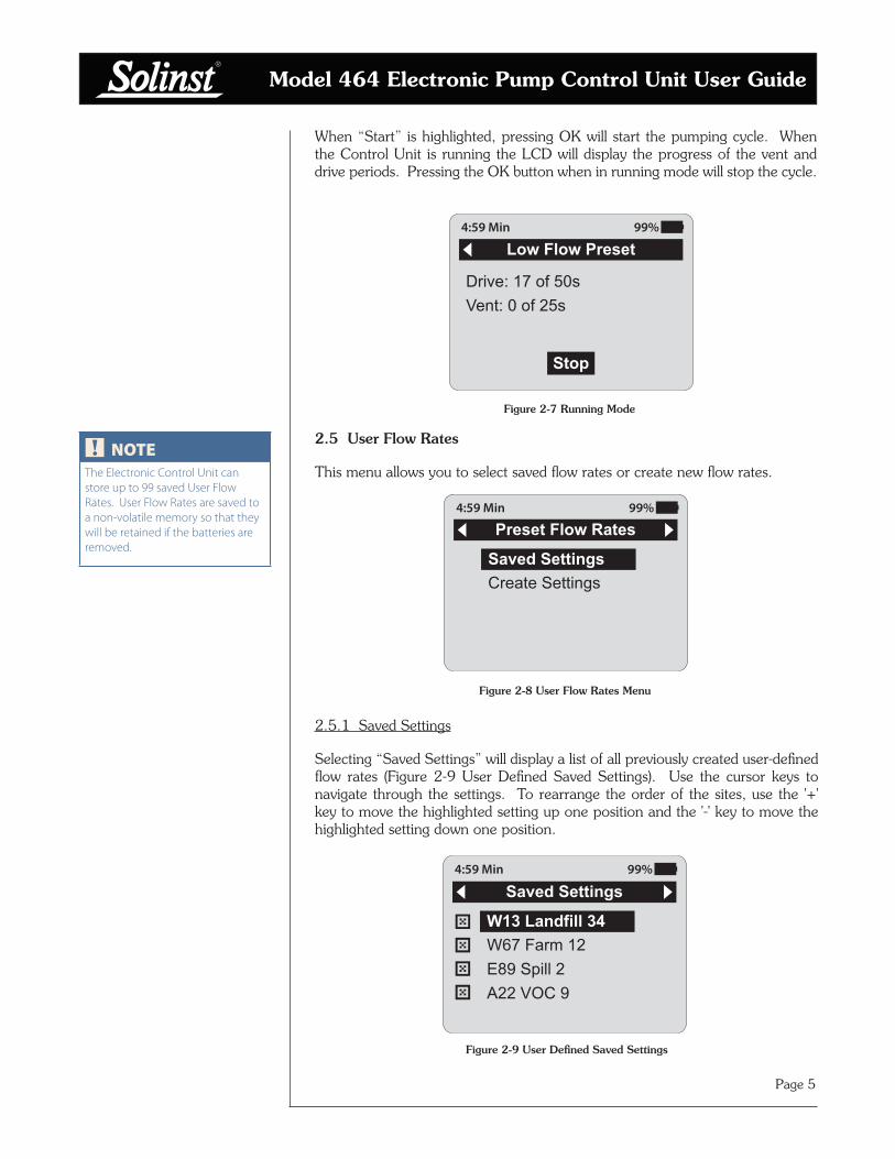
When “Start” is highlighted, pressing OK will start the pumping cycle. When the Control Unit is running the LCD will display the progress of the vent and drive periods. Pressing the OK button when in running mode will stop the cycle.
Figure 2-7 Running Mode
Drive: 17 of 50sVent: 0 of 25s
Low Flow Preset
Stop
4:59 Min 99%
2.5 User Flow Rates
This menu allows you to select saved flow rates or create new flow rates.
Figure 2-8 User Flow Rates Menu
2.5.1 Saved Settings
Selecting “Saved Settings” will display a list of all previously created user-defined flow rates (Figure 2-9 User Defined Saved Settings). Use the cursor keys to navigate through the settings. To rearrange the order of the sites, use the '+' key to move the highlighted setting up one position and the '-' key to move the highlighted setting down one position.
Figure 2-9 User Defined Saved Settings
Create Settings
Preset Flow Rates
Saved Settings
4:59 Min 99%
W67 Farm 12E89 Spill 2A22 VOC 9
Saved Settings
W13 Landfill 34
4:59 Min 99%
NOTEThe Electronic Control Unit can store up to 99 saved User Flow Rates. User Flow Rates are saved to a non-volatile memory so that they will be retained if the batteries are removed.
Model 464 Electronic Pump Control Unit User Guide
Page 6
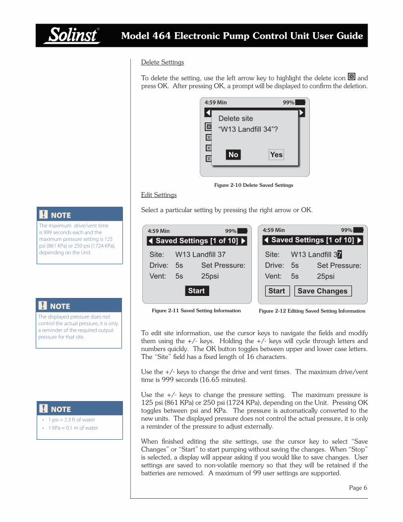
Delete Settings
To delete the setting, use the left arrow key to highlight the delete icon and press OK. After pressing OK, a prompt will be displayed to confirm the deletion.
Figure 2-10 Delete Saved Settings
W67 Farm 12E89 Spill 2A22 VOC 9
Saved Settings
W13 Landfill 34Delete site“W13 Landfill 34”?
YesNo
4:59 Min 99%
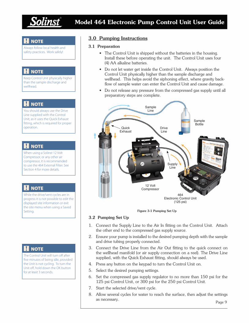
Edit Settings
Select a particular setting by pressing the right arrow or OK.
Figure 2-11 Saved Setting Information
To edit site information, use the cursor keys to navigate the fields and modify them using the +/- keys. Holding the +/- keys will cycle through letters and numbers quickly. The OK button toggles between upper and lower case letters. The “Site” field has a fixed length of 16 characters.
Use the +/- keys to change the drive and vent times. The maximum drive/vent time is 999 seconds (16.65 minutes).
Use the +/- keys to change the pressure setting. The maximum pressure is 125 psi (861 KPa) or 250 psi (1724 KPa), depending on the Unit. Pressing OK toggles between psi and KPa. The pressure is automatically converted to the new units. The displayed pressure does not control the actual pressure, it is only a reminder of the pressure to adjust externally.
When finished editing the site settings, use the cursor key to select “Save Changes” or “Start” to start pumping without saving the changes. When “Stop” is selected, a display will appear asking if you would like to save changes. User settings are saved to non-volatile memory so that they will be retained if the batteries are removed. A maximum of 99 user settings are supported.
Figure 2-12 Editing Saved Setting Information
Site: W13 Landfill 37Drive: 5s Set Pressure:Vent: 5s 25psi
Saved Settings [1 of 10]
Start
4:59 Min 99%
Site: W13 Landfill 37Drive: 5s Set Pressure:Vent: 5s 25psi
Saved Settings [1 of 10]
Start Save Changes
4:59 Min 99%
NOTEThe maximum drive/vent time is 999 seconds each and the maximum pressure setting is 125 psi (861 KPa) or 250 psi (1724 KPa), depending on the Unit.
NOTEThe displayed pressure does not control the actual pressure, it is only a reminder of the required output pressure for that site.
NOTE• 1 psi = 2.3 ft of water
• 1 KPa = 0.1 m of water

Model 464 Electronic Pump Control Unit User Guide
Page 7
2.5.2 Create Setting
To create a new setting, select “Create Setting” from the User Flow Rates menu. Enter the new site name, drive/vent times, and pressure setting using the cursor keys and +/- keys (see Edit Settings Section). Once you are finished programming the settings, use the cursor key to highlight “Save” and press OK.
Figure 2-13 Creating a New Site
Site: Drive: 0s Set Pressure:Vent: 0s 0psi
Create Setting
Save
4:59 Min 99%
2.6 Automatic Drive/Vent Cycles
Select the desired setting. To start the drive/vent cycles, use the cursor key to highlight “Start” and press OK. When the Control Unit is running, the LCD will display the progress of the vent and drive cycles. Pressing the OK button when in running mode will stop the drive/vent cycles.
Figure 2-14 Running Mode
Site: W13 Landfill 37Drive: 0 of 5sVent: 4 of 5 s
Saved Settings [1 of 10]
Stop
4:59 Min 99%
NOTEWhile the drive/vent cycles are in progress it is not possible to edit the displayed site information or exit the site menu. The only option is to push OK, to stop the cycling.

Model 464 Electronic Pump Control Unit User Guide
Page 8
2.7 Manual Drive/Vent Cycles
The 464 Electronic Control Unit can also be operated manually if preferred. It provides an alternative if the battery power runs out.
To operate the Control Unit manually, set up and connect the pump, Control Unit and compressed gas supply (see Section 3.2 Pumping Set Up). Apply the compressed gas to the Control Unit.
Use the Regulator on the Control Unit to decrease or increase the pumping pressure. To create a drive/vent cycle, use the Manual Control Button on the Control Panel. When the Manual Control Button is pushed in, it opens the solenoid, which allows the compressed gas to be applied to the pump. When the button is released, it allows the unit to vent.
Figure 2-15 Model 464 Control Panel (125 psi)
Manual Control Button
Regulator
Air Out
Air In
Battery Enclosure
Pressure Gauge
If the battery level is low, the battery warning will be displayed after attempting to start a drive/vent cycle (Figure 2-16). The battery icon will also be flashing. Press OK to clear the warning message. It will not be possible to start the vent/drive cycling with a low battery. Replace the battery or operate the Control Unit manually using the Manual Control Button to continue (see Section 2.7 Manual Drive/Vent Cycles).
Figure 2-16 Low Battery Warning
User Flow RatesLCD ContrastAbout
ECU 464 Main Menu
Preset Flow RatesBattery Low!
Please replace oroperate manually
OK
4:59 Min 0%
2.8 Battery Replacement
NOTEThe maximum output pressure of the Electronic Control Unit is 125 psi or 250 psi, depending on the Unit.
NOTEThe “Battery Low!” warning will appear at about 0% battery level. This is a conservative battery level estimation based on normal operation.
Model 464 Electronic Pump Control Unit User Guide
Page 9
3.0 Pumping Instructions
3.1 Preparation
• The Control Unit is shipped without the batteries in the housing. Install these before operating the unit. The Control Unit uses four (4) AA alkaline batteries.
• Do not let water get inside the Control Unit. Always position the Control Unit physically higher than the sample discharge and wellhead. This helps avoid the siphoning effect, where gravity back- flow of sample water can enter the Control Unit and cause damage.
• Do not release any pressure from the compressed gas supply until all preparatory steps are complete.
Figure 3-1 Pumping Set Up
464 Electronic Control Unit
(125 psi)
Drive Line
Sample Line
Supply Line
12 Volt Compressor
Sample Bottle
3.2 Pumping Set Up
1. Connect the Supply Line to the Air In fitting on the Control Unit. Attach the other end to the compressed gas supply source.
2. Ensure your pump is installed to the desired pumping depth with the sample and drive tubing properly connected.
3. Connect the Drive Line from the Air Out fitting to the quick connect on the wellhead manifold (or air supply connection on a reel). The Drive Line supplied, with the Quick Exhaust fitting, should always be used.
4. Press any button on the keypad to turn the Control Unit on.
5. Select the desired pumping settings.
6. Set the compressed gas supply regulator to no more than 150 psi for the 125 psi Control Unit, or 300 psi for the 250 psi Control Unit.
7. Start the selected drive/vent cycle.
8. Allow several cycles for water to reach the surface, then adjust the settings as necessary.
Quick Exhaust
NOTEAlways follow local health and safety practices. Work safely!
NOTEKeep Control Unit physically higher than the sample discharge and wellhead.
NOTEWhile the drive/vent cycles are in progress it is not possible to edit the displayed site information or exit the site menu when using a Saved Setting.
NOTEThe Control Unit will turn off after five minutes of being idle, provided the Unit is not cycling. To turn the Unit off, hold down the OK button for at least 3 seconds.
NOTEYou should always use the Drive Line supplied with the Control Unit, as it uses the Quick Exhaust fitting, which is required for proper operation.
NOTEWhen using a Solinst 12 Volt Compressor, or any other air compressor, it is recommended to use the 464 External Filter. See Section 4 for more details.
Model 464 Electronic Pump Control Unit User Guide
Page 10
3.3 Pump Optimization
Bladder Pumps
• Select and start your desired flow rate from the User Flow Rates menu.
• If higher flow rate is required, stop the drive/vent cycle to allow editing of the set up. Increase the drive time to increase the flow rate.
• If increasing the drive time no longer increases the flow rate, increase the vent time, then re-adjust the drive time to obtain the highest flow rate.
Double Valve Pumps
• Select and start your desired flow rate from the User Flow Rates menu.
• If a higher flow rate is required, stop the drive/vent cycle to allow editing of the set up. Slowly increase the drive time to increase the flow rate.
• If air is expelled, decrease the drive time.
• To further optimize the flow rate, increase or decrease the vent time until the highest flow rate is achieved.
Once optimization has been done, remember to save the settings for subsequent sampling events.
Model 464 Electronic Pump Control Unit User Guide
Page 11
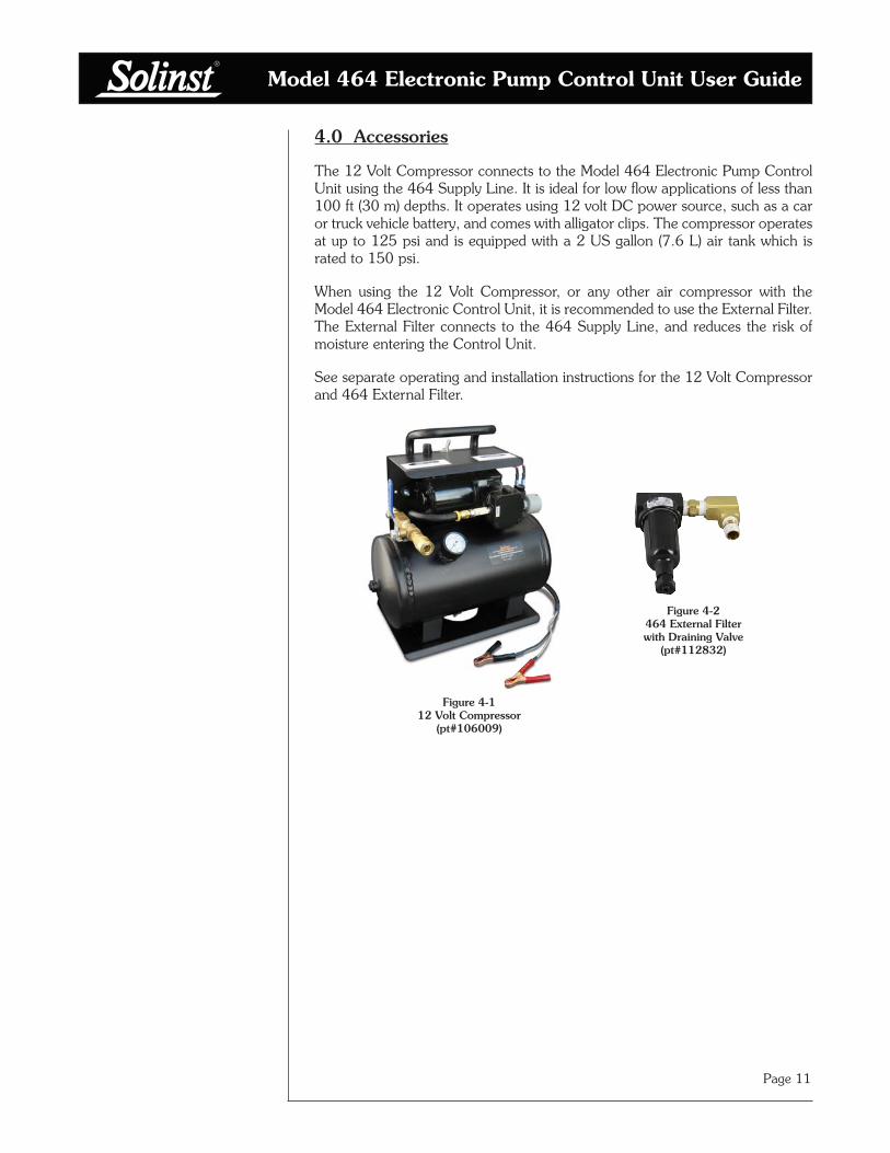
4.0 Accessories
The 12 Volt Compressor connects to the Model 464 Electronic Pump Control Unit using the 464 Supply Line. It is ideal for low flow applications of less than 100 ft (30 m) depths. It operates using 12 volt DC power source, such as a car or truck vehicle battery, and comes with alligator clips. The compressor operates at up to 125 psi and is equipped with a 2 US gallon (7.6 L) air tank which is rated to 150 psi.
When using the 12 Volt Compressor, or any other air compressor with the Model 464 Electronic Control Unit, it is recommended to use the External Filter. The External Filter connects to the 464 Supply Line, and reduces the risk of moisture entering the Control Unit.
See separate operating and installation instructions for the 12 Volt Compressor and 464 External Filter.
Figure 4-1 12 Volt Compressor
(pt#106009)
Figure 4-2
464 External Filter with Draining Valve
(pt#112832)

Model 464 Electronic Pump Control Unit User Guide
Page 12
5.0 Maintenance
Moisture in the Model 464 Electronic Pump Control Unit can shorten the lifetime of some of its components. After each sampling session, compressed air or nitrogen should be sent through the Pump Control Unit to ensure that any build-up of moisture is purged and pushed out of the Pump Control Unit, as well as through the Supply and Drive Lines.
Connect the compressed air/nitrogen gas source and let it cycle through the Pump Control Unit with the drive line disconnected at the pneumatic pump. Set a 10 second "Drive Time" and 2 second "Vent Time". This will create a pulse of air to purge the system components. Maintain this purging cycle for 10 minutes.
If you are using the 464 External Filter, use the draining valve as necessary to prevent water from entering the 464 Electronic Pump Control Unit.
Of note, sources of moisture may include:
1. The air compressor - follow the manufacture's suggestions for routine maintenance for draining the air tank from a build-up of moisture.
2. Sample backflow - best practice is to maintain the Control Unit at a higher elevation than the Drive Line connection at the wellhead. This height difference reduces the potential for backflow into the Control Unit.
3. Precipitation - avoid direct exposure to precipitation or water splashing; - ensure that your Control Unit is stored dry, inside and out.

Model 464 Electronic Pump Control Unit User Guide
Page 13
6.0 Storage
The Pump Control Unit should be purged with compressed air after use, as described in Section 5.0, then stored in a dry condition.
Ensure the 464 External Filter is dry before storage.
If the Pump Control Unit is going to be stored for longer than a two month period, the four alkaline batteries should be removed to avoid any potential leakage.

Solinst Canada Ltd., 35 Todd Road, Georgetown, ON L7G 4R8 Fax: +1 (905) 873-1992; (800) 516-9081 Tel: +1 (905) 873-2255; (800) [email protected]
www.solinst.com
High Quality Groundwater and Surface Water Monitoring Instrumentation