model 136-cb - cla-val products and services · cla-val 136-cb solenoid control valve s u p p l y...
TRANSCRIPT

CLA-VAL 136-CBSolenoid
Control Valve
SUPPLYElectricalSignal
IsolationValve
CLA-VAL 136-CBSolenoid
Control Valve
TANK
Solenoid Control Valve
Industrial uses for the solenoid control valve are manyand include accurate control of process water forbatching, mixing, washing, blending or other on-off typeuses.
Liquid level control can be provided by using a float switch orelectrode probe which sends an electrical signal to open orclose the valve as needed.
Schematic Diagram Item Description 1 100-01 Hytrol Main Valve 2 CSM11-HC Solenoid Control Optional Features Item Description A X46A Flow Clean Strainer B CK2 Isolation Valve C CNA Closing Speed Control D Check Valves with Isolation Valve F Independent Operating Pressure H Atmospheric Drain P X141 Pressure Gauge S CNA Needle Valve (Opening) V X101 Valve Position Indicator Y X43 "Y" Strainer
Typical Applications
• Fast Acting Solenoid Control• Reliable, Drip-Tight Shut-Off• Simple Design, Proven Reliable• Optional Check Feature• Easy Installation and MaintenanceThe Cla-Val Model 136-CB Solenoid Control Valve is anon-off control valve that either opens or closes upon receivingan electrical signal to the solenoid control. This valve consists of a Hytrolmain valve and the CSM11-HC solenoid pilot control that alternatelyapplies pressure to or relieves pressure from the diaphragm chamber ofthe main valve. It is furnished either normally open (de-energizedsolenoid to open) or normally closed (energized solenoid to open).If the check feature option is added and a pressure reversal occurs, thedownstream pressure is admitted into the main valve cover chamber andthe valve closes to prevent return flow.
MODEL 136-CB

Model 136-CB (Uses Hytrol Main Valve Model 100-01)
Model 136-CB Dimensions (inches)
Component Standard Material CombinationsBody & Cover Ductile Iron Cast Steel Bronze
Available Sizes 6" - 16"150 - 400mm
6" - 16"150 - 400mm
6" - 16"150 - 400mm
Disc Retainer &Diaphragm Washer Cast Iron Cast Steel BronzeTrim: Disc Guide, Seat & Cover Bearing
Bronze is StandardStainless Steel is Optional
Disc Buna-N® RubberDiaphragm Nylon Reinforced Buna-N® RubberStem, Nut & Spring Stainless SteelFor material options not listed, consult factory.Cla-Val manufactures valves in more than 50 different alloys.
Materials
GGGG
DDDDInlet
AAAA
X
100-01Grooved
EE
CC(MAX)
K
J
H
Inlet Outlet
B (Diameter)
Y
Z
GGGGGG
DInletDDDDD
FFF
X
100-01Threaded &
Flanged
A
E
C(MAX)
K
J
H
Inlet Outlet
AAAAA
B (Diameter)
Valve Body & CoverPressure Class
Flanged Grooved Threaded
Grade Material ANSIStandards*
150Class
300Class
300Class
End‡Details
ASTM A536 Ductile Iron B16.42 250 400 400 400
ASTM A216-WCB Cast Steel B16.5 285 400 400 400
UNS 87850 Bronze B16.24 225 400 400 400
Note: * ANSI standards are for flange dimensions only. Flanged valves are available faced but not drilled. ‡ End Details machined to ANSI B2.1 specifications.
Valves for higher pressure are available; consult factory for details
Pressure Ratings (Recommended Maximum Pressure - psi)
Valve Size (Inches) 3 4 6 8 10 12 14 16A Threaded 12.50 — — — — — — —AA 150 ANSI 12.00 15.00 20.00 25.38 29.75 34.00 39.00 41.38AAA 300 ANSI 13.25 15.62 21.00 26.38 31.12 35.50 40.50 43.50AAAA Grooved End 12.50 15.00 20.00 25.38 — — — —B Diameter 9.12 11.50 15.75 20.00 23.62 28.00 32.75 35.50C Maximum 8.19 10.62 13.38 16.00 17.12 20.88 24.19 25.00CC Maximum Grooved End 7.25 9.31 12.12 14.62 — — — —D Threaded 6.25 — — — — — — —DD 150 ANSI 6.00 7.50 10.00 12.69 14.88 17.00 19.50 20.81DDD 300 ANSI 6.38 7.88 10.50 13.25 15.56 17.75 20.25 21.62DDDD Grooved End 6.00 7.50 — — — — — —E 2.06 3.19 4.31 5.31 9.25 10.75 12.62 15.50EE Grooved End 3.12 4.25 6.00 7.56 — — — —F 150 ANSI 3.75 4.50 5.50 6.75 8.00 9.50 10.50 11.75FF 300 ANSI 4.13 5.00 6.25 7.50 8.75 10.25 11.50 12.75G Threaded 4.50 — — — — — — —GG 150 ANSI 4.00 5.00 6.00 8.00 8.62 13.75 14.88 15.69GGG 300 ANSI 4.38 5.31 6.50 8.50 9.31 14.50 15.62 16.50GGGG Grooved End 4.25 5.00 — — — — — —H NPT Body Tapping 0.50 0.75 0.75 1.00 1.00 1.00 1.00 1.00J NPT Cover Center Plug 0.50 0.75 0.75 1.00 1.00 1.25 1.50 2.00K NPT Cover Tapping 0.50 0.75 0.75 1.00 1.00 1.00 1.00 1.00Stem Travel 0.80 1.10 1.70 2.30 2.80 3.40 4.00 4.50Approx. Ship Weight (lbs) 70 140 285 500 780 1165 1600 2265Approx. X Pilot System 15 17 29 31 33 36 40 40Approx. Y Pilot System 11 12 20 22 24 26 29 30Approx. Z Pilot System 11 12 20 22 24 26 29 30

Model 136-CB Dimensions (mm)
Model 136-CB Metric Dimensions (Uses 100-01 Hytrol Main Valve)
Valve Size (mm) 80 100 150 200 250 300 350 400A Threaded 318 — — — — — — —AA 150 ANSI 305 381 508 645 756 864 991 1051AAA 300 ANSI 337 397 533 670 790 902 1029 1105AAAA Grooved End 318 381 508 645 — — — —B Diameter 232 292 400 508 600 711 832 902C Maximum 208 270 340 406 435 530 614 635CC Maximum Grooved End 184 236 308 371 — — — —D Threaded 159 — — — — — — —DD 150 ANSI 152 191 254 322 378 432 495 528DDD 300 ANSI 162 200 267 337 395 451 514 549DDDD Grooved End 152 191 — — — — — —E 52 81 110 135 235 273 321 394EE Grooved End 79 108 152 192 — — — —F 150 ANSI 95 114 140 171 203 241 267 298FF 300 ANSI 105 127 159 191 222 260 292 324G Threaded 114 — — — — — — —GG 150 ANSI 102 127 152 203 219 349 378 399GGG 300 ANSI 111 135 165 216 236 368 397 419GGGG Grooved End 108 127 — — — — — —H NPT Body Tapping 0.50 0.75 0.75 1.00 1.00 1.00 1.00 1.00J NPT Cover Center Plug 0.50 0.75 0.75 1.00 1.00 1.25 1.50 2.00K NPT Cover Tapping 0.50 0.75 0.75 1.00 1.00 1.00 1.00 1.00Stem Travel 20 28 43 58 71 86 102 114Approx. Ship Weight (kgs) 32 64 129 227 354 528 726 1027Approx. X Pilot System 381 432 737 788 839 915 1016 1016Approx. Y Pilot System 280 305 508 559 610 661 737 762Approx. Z Pilot System 280 305 508 559 610 661 737 762
GGGG
DDDDInlet
AAAA
X
100-01Grooved
EE
CC(MAX)
K
J
H
Inlet Outlet
B (Diameter)
Y
Z
GGGGGG
DInletDDDDD
FFF
X
100-01Threaded &
Flanged
A
E
C(MAX)
K
J
H
Inlet Outlet
AAAAA
B (Diameter)
CLA-VAL 1701 Placentia Ave • Costa Mesa CA 92627 • Phone: 949-722-4800 • Fax: 949-548-5441 • E-mail: [email protected] • www.cla-val.com Copyright Cla-Val 2019 • Printed in USA • Specifications subject to change without notice.© E-136-CB (R-01/2019)
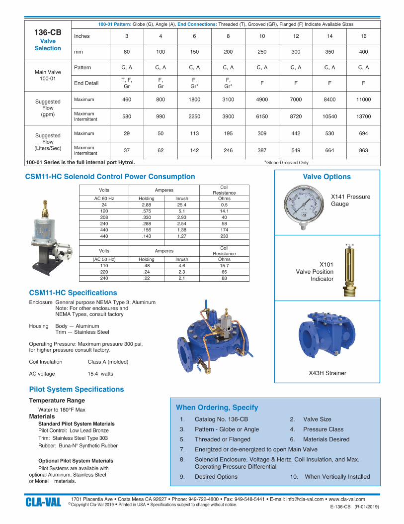
When Ordering, Specify 1. Catalog No. 136-CB 2. Valve Size 3. Pattern - Globe or Angle 4. Pressure Class 5. Threaded or Flanged 6. Materials Desired 7. Energized or de-energized to open Main Valve 8. Solenoid Enclosure, Voltage & Hertz, Coil Insulation, and Max.
Operating Pressure Differential 9. Desired Options 10. When Vertically Installed
Valve Options
X141 PressureGauge
X43H Strainer
X101 Valve Position
Indicator
136-CBValve
Selection
100-01 Pattern: Globe (G), Angle (A), End Connections: Threaded (T), Grooved (GR), Flanged (F) Indicate Available Sizes
Inches 3 4 6 8 10 12 14 16
mm 80 100 150 200 250 300 350 400
Main Valve100-01
Pattern G, A G, A G, A G, A G, A G, A G, A G, A
End Detail T, F,Gr
F, Gr
F, Gr*
F, Gr* F F F F
Suggested Flow (gpm)
Maximum 460 800 1800 3100 4900 7000 8400 11000
Maximum Intermittent 580 990 2250 3900 6150 8720 10540 13700
Suggested Flow
(Liters/Sec)
Maximum 29 50 113 195 309 442 530 694
Maximum Intermittent 37 62 142 246 387 549 664 863
100-01 Series is the full internal port Hytrol. *Globe Grooved Only
Temperature Range Water to 180°F Max Materials Standard Pilot System Materials Pilot Control: Low Lead Bronze Trim: Stainless Steel Type 303 Rubber: Buna-N® Synthetic Rubber
Optional Pilot System Materials Pilot Systems are available with optional Aluminum, Stainless Steel or Monel materials.
Pilot System Specifications
CSM11-HC Solenoid Control Power Consumption
Enclosure General purpose NEMA Type 3; Aluminum Note: For other enclosures and NEMA Types, consult factory
Housing Body — Aluminum Trim — Stainless Steel
Operating Pressure: Maximum pressure 300 psi,for higher pressure consult factory.
Coil Insulation Class A (molded)
AC voltage 15.4 watts
Volts Amperes CoilResistance
AC 60 Hz Holding Inrush Ohms24 2.88 25.4 0.5
120 .575 5.1 14.1208 .330 2.93 40240 .288 2.54 58440 .156 1.38 174440 .143 1.27 233
Volts Amperes CoilResistance
(AC 50 Hz) Holding Inrush Ohms110 .48 4.6 15.7220 .24 2.3 66240 .22 2.1 88
CSM11-HC Specifications