modbus option board - danfoss
TRANSCRIPT
vacon nxpac drives
optcg s2 option board
selma application (apfien04)
user manual

2 • vacon index
Tel. +358 (0)201 2121 • Fax +358 (0)201 212 205
INDEX
Document code: DPD00894A Date:17.01.2012
1. GENERAL ........................................................................................................................... 4
2. INSTALLATION ................................................................................................................... 5
3. CONNECTIONS ................................................................................................................... 7 3.1 Jumper settings ....................................................................................................................... 7
3.1.1 Jumper settings of 4CMO board with OPT-CG: ............................................................... 7 3.1.2 Jumper settings of 4CM board with OPT-CG: .................................................................. 8
4. COMMISSIONING ................................................................................................................ 9 4.1 Parameters ............................................................................................................................... 9 4.2 LED indications ......................................................................................................................... 9
5. OPT-CG Config tool .......................................................................................................... 10
6. Selma application (APFIEN04) .......................................................................................... 12 6.1 Introduction ............................................................................................................................ 12 6.2 Control I/O .............................................................................................................................. 13 6.3 “Terminal to function” (TTF) programming principle ............................................................ 14
6.3.1 Defining an input/output for a certain function on keypad ............................................ 14 6.3.2 Defining a terminal for a certain function with NCDrive programming tool ................. 15
6.4 Selma Application – Parameter lists ..................................................................................... 16 6.4.1 M1 > V1.1 Monitor page 1 ............................................................................................... 17 6.4.2 M1>V1.2 Monitor Page 2 ................................................................................................. 17 6.4.3 Basic parameters ........................................................................................................... 19 6.4.4 Input signals (Control keypad: Menu M2 G2.2) ........................................................... 20 6.4.5 Output signals (Control keypad: Menu M2 G2.3) ....................................................... 24 6.4.6 Reference handling (Control keypad: Menu M2 G2.4) ............................................... 26 6.4.7 Ramp functions (Control keypad: Menu M2 G2.5) ..................................................... 27 6.4.8 Drive control (Control keypad: Menu M2 G2.6) .......................................................... 28 6.4.9 Motor control (Control keypad: Menu M2 G2.7) ......................................................... 30 6.4.10 Limit settings (Control keypad: Menu M2 G2.8) ..................................................... 32 6.4.11 Speed control (Control keypad: Menu M2 G2.9) .................................................... 33 6.4.12 Oscillation damp (Control keypad: Menu M2 G2.10) .............................................. 34 6.4.13 Brake & fan control (Control keypad: Menu M2 G2.11) .......................................... 34 6.4.14 Master Follower (Control keypad: Menu M2 G2.12) .............................................. 35 6.4.15 Protections (Control keypad: Menu M2 G2.13) ...................................................... 35 6.4.16 Flux reference handling (Control keypad: Menu M2 G2.14) .................................. 37 6.4.17 Startup torque (Control keypad: Menu M2 G2.15) ................................................. 37 6.4.18 DAC (Control keypad: Menu M2 G2.16) .................................................................. 38 6.4.19 Data mapping (Control keypad: Menu M2 G2.17) .................................................. 38 6.4.20 Keypad control (Control keypad: Menu M3 R3.1) .................................................. 38 6.4.21 Expander boards (Control keypad: Menu M7) ............................................................ 38
6.5 Description of parameters ..................................................................................................... 39 6.5.1 Basic parameters ........................................................................................................... 39 6.5.2 Input signals ................................................................................................................... 42 6.5.3 Output signals................................................................................................................. 49

vacon • 3
24-hour support +358 (0)40 837 1150 • Email: [email protected]
6.5.4 Reference handling ........................................................................................................ 50 6.5.5 Ramp funcions ................................................................................................................ 52 6.5.6 Drive control ................................................................................................................... 53 6.5.7 Motor control .................................................................................................................. 57 6.5.8 PMSM control ................................................................................................................. 60 6.5.9 Limit settings .................................................................................................................. 61 6.5.10 Speed control ............................................................................................................. 62 6.5.11 Oscillation damp ......................................................................................................... 66 6.5.12 Brake and fan control ................................................................................................. 66 6.5.13 Master Follower ......................................................................................................... 67 6.5.14 Protections ................................................................................................................. 69 6.5.15 Flux reference handling ............................................................................................. 74 6.5.16 Startup torque ............................................................................................................ 75 6.5.17 Monitor settings ......................................................................................................... 76 6.5.18 Data mapping ............................................................................................................. 76
6.6 Fieldbus profile....................................................................................................................... 77 6.6.1 Process data signals from overriding system to Vacon drive. ....................................... 77 6.6.2 Process data signals from Vacon drive to overriding system. ....................................... 77 6.6.3 Main control word, par. 2.17.17 (FB Mode) = 1-3 ........................................................... 78 6.6.4 Selma Control Word, par. 2.17.17 (FB Mode) = 4 ........................................................... 78 6.6.5 Main status word ............................................................................................................ 79 6.6.6 Selma Status Word ......................................................................................................... 79 6.6.7 Micro Status Word .......................................................................................................... 80 6.6.8 Auxiliary control word .................................................................................................... 80 6.6.9 Auxiliary status word ...................................................................................................... 81 6.6.10 Fault word 1 ................................................................................................................ 81 6.6.11 Fault word 2 ................................................................................................................ 82 6.6.12 Selma fault word 0 ..................................................................................................... 82 6.6.13 Selma fault word 1 ..................................................................................................... 83 6.6.14 Selma fault word 2 ..................................................................................................... 83 6.6.15 Alarm word 1 .............................................................................................................. 84 6.6.16 Digital input status word 1 ......................................................................................... 85 6.6.17 Digital input status word 2 ......................................................................................... 85
6.7 BLOCK DIAGRAMS.................................................................................................................. 86 6.8 FAULT TRACING ..................................................................................................................... 91
7. Appendix 1 ........................................................................................................................ 95
8. Appendix 2 ........................................................................................................................ 96

4 • vacon general
Tel. +358 (0)201 2121 • Fax +358 (0)201 212 205
1. GENERAL
Vacon NXP frequency converters can be connected to the Selma System (S2) using a fieldbus board. The converter can then be controlled, monitored and programmed from the host system. If you purchase your S2 option board separately, please note that it shall be installed in slot E or D on the control board of the frequency converter. For retrofit projects where existing software in the Selma System is to be used without changes, APFIEN04 application can be used. Note! S2 option board can only be used with Vacon NXP frequency converters
WARNING!
Internal components and circuit boards are at high potential when the frequency converter is connected to the power source. This voltage is extremely dangerous and may cause death or severe injury if you come into contact with it.
installation vacon • 5
24-hour support +358 (0)40 837 1150 • Email: [email protected] 2
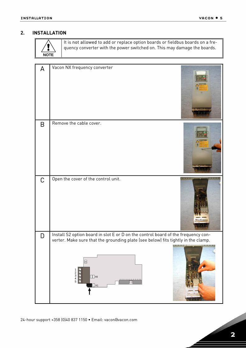
2. INSTALLATION
!NOTE
It is not allowed to add or replace option boards or fieldbus boards on a fre-quency converter with the power switched on. This may damage the boards.
A Vacon NX frequency converter
B Remove the cable cover.
C Open the cover of the control unit.
D Install S2 option board in slot E or D on the control board of the frequency con-verter. Make sure that the grounding plate (see below) fits tightly in the clamp.
X 6
X 1
1 2 3 4 5

6 • vacon installation
Tel. +358 (0)201 2121 • Fax +358 (0)201 212 205 2
E Make a sufficiently wide opening for your cable by cutting the grid as wide as necessary.
F Close the cover of the control unit and the cable cover.
NOTE! Ground the OPT-CG cable shield as shown below:
NOTE! Perform this grounding only at Vacon’s end!
commissioning vacon • 7
24-hour support +358 (0)40 837 1150 • Email: [email protected] 4
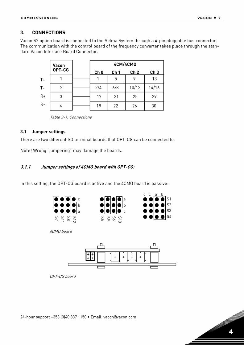
3. CONNECTIONS
Vacon S2 option board is connected to the Selma System through a 4-pin pluggable bus connector. The communication with the control board of the frequency converter takes place through the stan-dard Vacon Interface Board Connector.
1
2
3
VaconOPT-CG
4
4CM/4CMO
Ch 0 Ch 1 Ch 2 Ch 31 5 9 13
2/4 6/8 10/12 14/16
17 21 25 29
18 22 26 30
Table 3-1. Connections
3.1 Jumper settings
There are two different I/O terminal boards that OPT-CG can be connected to. Note! Wrong “jumpering” may damage the boards. 3.1.1 Jumper settings of 4CMO board with OPT-CG:
In this setting, the OPT-CG board is active and the 4CMO board is passive:
4CMO board
++++ + + + +
OPT-CG board
S11 S7
S8 S12
S9 S5
S6 S10
S1 d c a b
S4 S3 S2
c
b
a
a
b
c
T+
T-
R+
R-

8 • vacon connections
Tel. +358 (0)201 2121 • Fax +358 (0)201 212 205 3
3.1.2 Jumper settings of 4CM board with OPT-CG:
In this setting, the OPT-CG board is passive and the 4CM board is active:
4CM board
+ + + +
OPT-CG board
S1
c a b
S2
c a b
S4
c a b
S3
c a b

commissioning vacon • 9
24-hour support +358 (0)40 837 1150 • Email: [email protected] 4
4. COMMISSIONING
4.1 Parameters
Parameters are visible in keypad in menu M7/Expander boards in the corresponding slot in which S2 option board is installed (D/E).
# Name Default Range Description 1 BAUD RATE
6 5 – 4800 baud 6 – 9600 baud
Communication speed
2 COMMUNICATION TIMEOUT 20 1—600 s
See below
Table 4-1. The Parameters of S2
Communication timeout In case S2 option board doesn’t receive any messages from Selma System for the time defined by pa-rameter Communication Timeout, Vacon drive will trip on Fieldbus Communication (FB Comm.) fault.
4.2 LED indications
Status LED of S2 YELLOW
LED is: Meaning: OFF Option board is not active ON Option board is in configuration mode and waiting a permis-
sion from the frequency converter to move on to the normal operating mode
Blinking fast (once/sec)
Option board is in normal operating mode receiving mes-sages from the field (See Parametres and Time-Out)
Blinking slow (once/5 secs)
Option board did not receive any messages during the Time-Out and is in the fault mode
Status LED of S2 GREEN
LED is: Meaning: OFF Option board is in fault mode ON Option board is active.
10 • vacon config tool
Tel. +358 (0)201 2121 • Fax +358 (0)201 212 205 5
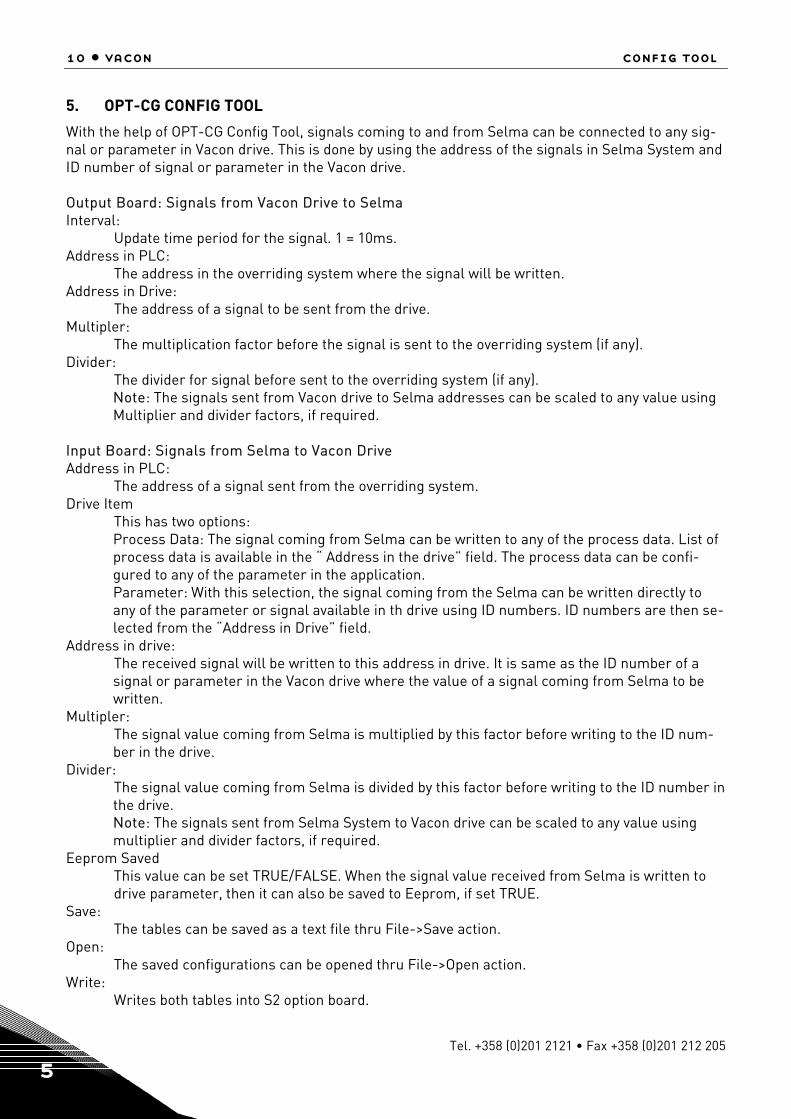
5. OPT-CG CONFIG TOOL
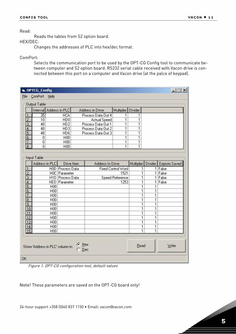
With the help of OPT-CG Config Tool, signals coming to and from Selma can be connected to any sig-nal or parameter in Vacon drive. This is done by using the address of the signals in Selma System and ID number of signal or parameter in the Vacon drive. Output Board: Signals from Vacon Drive to Selma Interval:
Update time period for the signal. 1 = 10ms. Address in PLC: The address in the overriding system where the signal will be written. Address in Drive: The address of a signal to be sent from the drive. Multipler: The multiplication factor before the signal is sent to the overriding system (if any). Divider: The divider for signal before sent to the overriding system (if any).
Note: The signals sent from Vacon drive to Selma addresses can be scaled to any value using Multiplier and divider factors, if required.
Input Board: Signals from Selma to Vacon Drive Address in PLC: The address of a signal sent from the overriding system. Drive Item This has two options:
Process Data: The signal coming from Selma can be written to any of the process data. List of process data is available in the “ Address in the drive” field. The process data can be confi-gured to any of the parameter in the application. Parameter: With this selection, the signal coming from the Selma can be written directly to any of the parameter or signal available in th drive using ID numbers. ID numbers are then se-lected from the “Address in Drive” field.
Address in drive: The received signal will be written to this address in drive. It is same as the ID number of a signal or parameter in the Vacon drive where the value of a signal coming from Selma to be written.
Multipler: The signal value coming from Selma is multiplied by this factor before writing to the ID num-ber in the drive.
Divider: The signal value coming from Selma is divided by this factor before writing to the ID number in the drive. Note: The signals sent from Selma System to Vacon drive can be scaled to any value using multiplier and divider factors, if required.
Eeprom Saved This value can be set TRUE/FALSE. When the signal value received from Selma is written to drive parameter, then it can also be saved to Eeprom, if set TRUE.
Save: The tables can be saved as a text file thru File->Save action.
Open: The saved configurations can be opened thru File->Open action.
Write: Writes both tables into S2 option board.
config tool vacon • 11
24-hour support +358 (0)40 837 1150 • Email: [email protected] 5
Read: Reads the tables from S2 option board. HEX/DEC: Changes the addresses of PLC into hex/dec format. ComPort:
Selects the communication port to be used by the OPT-CG Config tool to communicate be-tween computer and S2 option board. RS232 serial cable received with Vacon drive is con-nected between this port on a computer and Vacon drive (at the palce of keypad).
Figure 1. OPT-CG configuration tool, default values
Note! These parameters are saved on the OPT-CG board only!

12 • vacon selma application
Tel. +358 (0)201 2121 • Fax +358 (0)201 212 205 6
6. SELMA APPLICATION (APFIEN04)
6.1 Introduction
The Selma Application is typically used in coordinated drives with overriding control system. The rec-ommended interface to control the system is a fieldbus communication though hardwired analogue and digital signals as well as keypad and PC control can be used.
The Selma Application utilises most advanced functions in NXP motor control software and is suitable for demanding drive systems like paper machines and drives in metal industry and process-ing lines. It can also be used for any other standard applications. Following applications are working with this application.
• Pulp and paper machine drives like dryer, press section, wire section, pope reel, winder and un-winder.
• Drives in metal industry like casting machine, melt shop or preparing line • Standard drives like pump and fan, lifts, cranes, conveyors, etc. Additional functions:
• Flexible speed and torque reference chains. • Advanced drive control profile for fieldbus communication • Flexible fieldbus data connections. • Adaptive speed controller. • Inertia compensation and oscillation damping features. • System Bus support for master follower applications with speed/torque follower. • Fast and multi drive monitoring tool (NCDrive) support. • Programmable U/f curve and flux curve. • Speed /torque-selector options, window control • Automatic identification run • Support to permanent magnet motors and multiple winding motors

selma application vacon • 13
24-hour support +358 (0)40 837 1150 • Email: [email protected] 6
6.2 Control I/O
Terminal Signal Description 1 +10V Reference output Voltage for potentiometer, etc. 2 AI1+ Analogue input, voltage
range 0—10V DC Voltage input frequency reference
3 AI1- I/O Ground Ground for reference and controls 4 AI2+ Analogue input, current
range 0—20mA Current input frequency reference 5 AI2-
6 +24V Control voltage output Voltage for switches, etc. max 0.1 A 7 GND I/O ground Ground for reference and controls 8 DIN1 Start forward
(Programmable) Contact closed = start forward
9 DIN2 Start reverse (Programmable)
Contact closed = start reverse
10 DIN3 External fault input (programmable)
Contact open = no fault Contact closed = fault
11 CMA
Common for DIN 1—DIN 3
Connect to GND or +24V
12 +24V Control voltage output Voltage for switches (see #6) 13 GND I/O ground Ground for reference and controls 14 DIN4 Run Enable Contact closed = Run Enable
Contact Open =Run Disable 15 DIN5 Main Switch Ack. Contact closed = Switch is closed.
Contact Open= Switch is open. 16 DIN6 Emergency Stop
Contact open= EmstopActive. Con-tact Close = Emstop not active.
17 CMB Common for DIN4—DIN6
Connect to GND or +24V
18 AOA1+ Programmable Programmable Range 0—20 mA/RL, max. 500Ω 19 AOA1-
20 DOA1 Digital output READY
Programmable Open collector, I≤50mA, U≤48 VDC
21 RO1 Relay output 1 RUN
Programmable 22 RO1 23 RO1 24 RO2 Relay output 2
DC bus Charging OK Programmable
25 RO2 26 RO2
Table 2. Selma Application default I/O configuration.
Note: The above I/O configuration is an example. Most of the I/Os are programmable.
mA
READY
RUN
220 VAC
14 • vacon selma application
Tel. +358 (0)201 2121 • Fax +358 (0)201 212 205 6
6.3 “Terminal to function” (TTF) programming principle
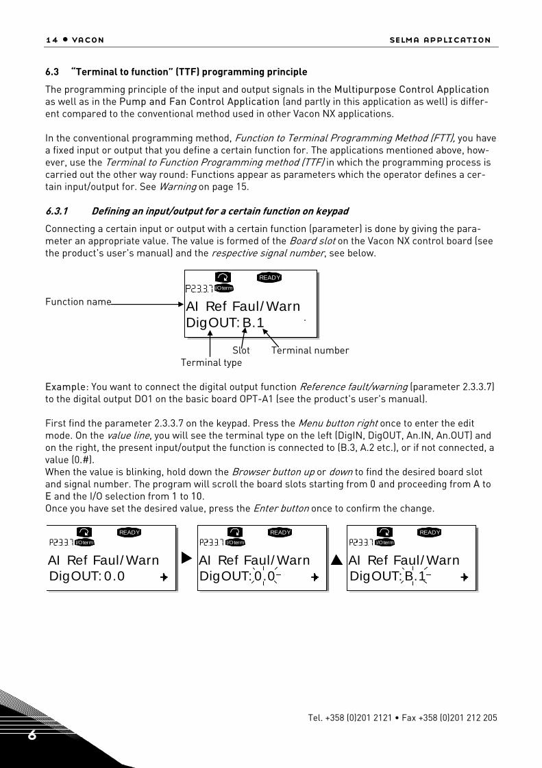
The programming principle of the input and output signals in the Multipurpose Control Application as well as in the Pump and Fan Control Application (and partly in this application as well) is differ-ent compared to the conventional method used in other Vacon NX applications. In the conventional programming method, Function to Terminal Programming Method (FTT), you have a fixed input or output that you define a certain function for. The applications mentioned above, how-ever, use the Terminal to Function Programming method (TTF) in which the programming process is carried out the other way round: Functions appear as parameters which the operator defines a cer-tain input/output for. See Warning on page 15. 6.3.1 Defining an input/output for a certain function on keypad
Connecting a certain input or output with a certain function (parameter) is done by giving the para-meter an appropriate value. The value is formed of the Board slot on the Vacon NX control board (see the product's user's manual) and the respective signal number, see below. Function name Slot Terminal number Terminal type Example: You want to connect the digital output function Reference fault/warning (parameter 2.3.3.7) to the digital output DO1 on the basic board OPT-A1 (see the product's user's manual). First find the parameter 2.3.3.7 on the keypad. Press the Menu button right once to enter the edit mode. On the value line, you will see the terminal type on the left (DigIN, DigOUT, An.IN, An.OUT) and on the right, the present input/output the function is connected to (B.3, A.2 etc.), or if not connected, a value (0.#). When the value is blinking, hold down the Browser button up or down to find the desired board slot and signal number. The program will scroll the board slots starting from 0 and proceeding from A to E and the I/O selection from 1 to 10. Once you have set the desired value, press the Enter button once to confirm the change.
READY
I/Oterm
DigOUT:B.1AI Ref Faul/Warn
READY
I/Oterm
DigOUT:0.0
READY
I/Oterm
DigOUT:0.0
READY
I/Oterm
DigOUT:B.1AI Ref Faul/Warn AI Ref Faul/Warn AI Ref Faul/Warn

selma application vacon • 15
24-hour support +358 (0)40 837 1150 • Email: [email protected] 6
6.3.2 Defining a terminal for a certain function with NCDrive programming tool
If you use the NCDrive Programming Tool for parametrizing you will have to establish the connection between the function and input/output in the same way as with the control panel. Just pick the ad-dress code from the drop-down menu in the Value column (see the Figure below).
Figure 6-1. Screenshot of NCDrive programming tool; Entering the address code
!WARNING
Be ABSOLUTELY sure not to connect two functions to one and same output in order to avoid function overruns and to ensure flawless operation.
Note: The inputs, unlike the outputs, cannot be changed in RUN state.
16 • vacon selma application
Tel. +358 (0)201 2121 • Fax +358 (0)201 212 205 6
6.4 Selma Application – Parameter lists
On the next pages you will find the lists of monitoring signals and parameters. The parameter de-scriptions are given on pages Error! Bookmark not defined. to Error! Bookmark not defined.. Column explanations: Code = Location indication on the keypad; Shows the operator the present parameter num-
ber Parameter = Name of parameter Min = Minimum value of parameter Max = Maximum value of parameter Unit = Unit of parameter value; given if available Step = Accuracy of smallest possible change of value Default = Value preset by factory ID = ID number of the parameter (used with PC tools)

selma application vacon • 17
24-hour support +358 (0)40 837 1150 • Email: [email protected] 6
6.4.1 M1 > V1.1 Monitor page 1 Code Parameter Unit ID Description
V1.1.1 Output frequency Hz 1
Frequency output from the drive to the motor.
V1.1.2 Speed Rpm 2
Motor speed in rpm. In open loop this is the calculated speed of the motor and in closed loop this is the filtered value of the speed measured from the encoder.
V1.1.3 Freq. Reference Hz 25 Frequency reference to the ramp generator. V1.1.4 Current A 3 Filtered motor current. V1.1.5 Torque % 4 Filtered motor torque in percentage of motor nominal torque. V1.1.6 Power % 5 Power in percentage of motor nominal power. V1.1.7 Motor voltage V 6 Motor terminal voltage. V1.1.8 DC-link voltage V 7 DC link voltage. V1.1.9 Unit tempertaure °C 8 Heat sink temperature. V1.1.10 DIN Status Word1 15 See 6.5.10 V1.1.11 DIN Status Word2 16 See 6.5.11
V1.1.12 MotorTempCalc % 9 Calculated motor temperature . 100.0% = nominal temperature of the motor.
V1.1.13 PT100(1) Temp. °C 50 Temperature of the PT100 type temperature sensor1 con-nected to Analogue input.
V1.1.14 PT100(2) Temp. °C 51 Temperature of the PT100 type temperature sensor2 con-nected to Analogue input.
V1.1.15 PT100(3) Temp. 52 V1.1.16 Unit nom. voltage V 1117 Nominal voltage rating of the drive unit.
V1.1.17 Unit nom. current A 1118 Nominal current rating of the drive unit. This is same as IL current rating of the unit.
V1.1.18 DC nom. Voltage V 1120 Nominal DC link voltage of the drive unit.
V1.1.19 ID Run status 49
Bitwise status of automatic identification after ID run. B0= Stator resistance and U7f curve B1= Reserved B2= Magnetisation current. B3= Flux linearization curve.
V1.1.20 Analogue Input 3 % V1.1.21 Analogue Input 4 % Table 3. Monitoring page 1
6.4.2 M1>V1.2 Monitor Page 2 Code Parameter Unit ID Description
V1.2.1 Speed Measured rpm
1124 Speed measured from the encoder.
V1.2.2 Torque Unfilt. % 1125 Unfiltered torque calculated by the drive.100% equals to motor nominal torque.
V1.2.3 Current Unfilt. % 1113 Unfiltered Motor current in Amperes. V1.2.4 Speed Reference1 rpm 1126 Speed reference selected as per the control place selection. V1.2.5 Speed Reference2 rpm 1127 Speed reference after speed share logic. V1.2.6 Speed Reference3 rpm 1128 Speed reference at the input of the ramp generator. V1.2.7 Speed Ramp Out rpm 1129 Final speed reference after Ramp generator
V1.2.8 Speed Reference4 rpm 1130 Speed reference after the speed correction is added to the Speed Ramp Out. 1)
V1.2.9 Used Speed Ref rpm 1131 Final speed reference after the speed step logic. 1) V1.2.10 Speed Error rpm 1132 Speed error=Speed Act –Speed Ref 1) V1.2.11 SPC OUT % 1134 Iq Reference from the speed controller output. 1) V1.2.12 Speed Limit Pos rpm 1135 Positive speed limit on the speed reference V1.2.13 Speed Lim Neg rpm 1136 Negative speed limit on the speed reference
V1.2.14 TC Speed Lim Pos rpm 1137 Positive speed limit when Torque Select is 2/3/4/5 and Motor Ctrl Mode =3.
V1.2.15 TC Speed Lim Neg rpm 1138 Negative speed limit when Torque Select is 2/3/4/5 and Motor Ctrl Mode =3.
V1.2.16 Master TorqueRef % 1139 Torque reference from Master Drive in case of master Fol-lower comm.

18 • vacon selma application
Tel. +358 (0)201 2121 • Fax +358 (0)201 212 205 6
Code Parameter Unit ID Description -300.0....+300.0% of the motor nominal torque
V1.2.17 FB Torque Ref % 1140 Torque Reference from the Fieldbus. -300.0...300.0%. of motor nominal torque
V1.2.18 I/0 Torque Ref % 1141 Torque Reference from the analogue Input -300.0...300.0%. of motor nominal torque
V1.2.19 Torque Ref1 % 1142 Torque reference after Torque Reference selector (Master, Fieldbus, analogue I/P)
V1.2.20 Torque Ref2 % 1143 Scaled Torque Reference V1.2.21 Torque Ref3 % 1144 Torque reference after Load Share logic. V1.2.22 Used Torque Ref % 1145 Final, limited torque reference for speed/torque controller
V1.2.23 Acc Comp Out % 1146 Acceleration compensation used in terms of IqRefer-ence.100.0% equals to motor nominal current. 1)
V1.2.24 Droop Speed RPM rpm 1147 Speed droop used in rpm. V1.2.25 Startup TorqAct A 1148 startup torque in use, 100.0 %= motor nominal torque.
V1.2.26 Iq Current Lim + % 1152 Final upper IqCurrentLimit 100.0 %= motor nominal current (unsigned)
V1.2.27 Iq Current Lim - % 1153 Final lower IqCurrentLimit 100.0 %= motor nominal current (unsigned)
V1.2.28 Iq Reference % 1154 Final IqReference, 100.0% = motor nominal current V1.2.29 Iq Actual % 1155 Measured Iq 100.0% = motor nominal current V1.2.30 Id Reference % 1156 Final IdReference 100.0% = motor nominal current V1.2.31 Id Actual % 1157 Measured Id 100.0 %= motor nominal current. V1.2.32 Flux % 1158 Estimated rotor flux in percentage of the motor nominal flux. V1.2.33 Rotor Time Const ms 1159 Rotor Time Constant in ms
V1.2.34 MainControlWord 1160 See 6.5.3
V1.2.35 AuxControlWord1 1161 See 6.5.8
V1.2.36 MainStatusWord 1162 See 6.5.5
V1.2.37 AuxStatusWord 1163 See 6.5.9
V1.2.38 Fault Word 1 1172 See 6.5.10
V1.2.39 Fault Word 2 1173 See 6.5.11
V1.2.40 Alarm Word 1 1174 See 6.5.15 V1.2.41 Max Brake Ramp 1168 Calculated ramp time in constant power emergency stop. V1.2.42 Shaft Position 1169 Position of the motor shaft in 0…360 Degrees. V1.2.43 Shaft Rounds 1170 No. of rounds of the motor shaft.
V1.2.44 Pole Pair Number 58
Number of pole pairs in the motor estimated from the motor data.
V1.2.45 Selma Status Word 69 See 6.5.6
V1.2.46 Selma Fault Word 0 1540 See 6.5.12 V1.2.47 Selma Fault Word 1 1541 See 6.5.13
V1.2.48 Selma Fault Word 2 1542 See 6.5.14 V1.2.49 Micro Status Word 1555 See 6.5.7
Selma Control Word See 6.5.4
V1.2.50 Drive output power 1508 Table 4. Monitoring page 2

selma application vacon • 19
24-hour support +358 (0)40 837 1150 • Email: [email protected] 6
6.4.3 Basic parameters
Code Parameter Min Max Unit Step Default ID Note
P2.1.1 Supply Voltage 0 1000 V 1 500 1201 Supply Voltage in Volts. If unknown then parameter should be zero.
P2.1.2 Motor Nom Volts 180 690 V 1 400 110 Nominal Voltage of the Motor in volts as per Rat-ing Plate
P2.1.3 Motor Nom Freq 30.00 320.00 Hz 0.01 50.00 111 Nominal Frequency of the Motor ##. ## Hz as per Rating Plate
P2.1.4 Motor Nom Cur-rent
Motor_ Cur-
rent_Min
Motor_ Cur-
rent_Max
A 0.1 113 Nominal Current of the Motor. in ####.# A
P2.1.5 Motor Nom Speed 300
Motor-Nom-
Speed-Max
rpm 1 1440 112 Nominal Speed of the Motor as per Rating Plate
P2.1.6 Motor Cos Phi 0.30 1.00 0.01 0.85 120 Rated value of cos phi as per Rating Plate
P2.1.7 Process Speed 0.0 3200.0 rpm 0.1 14400 1203 Process Speed limit in RPM scale
P2.1.8 Magn. Current 0.0 Motor Nom
Current A 0.1 0.5 612
Nominal magnetizing current of the motor in amps (Current Format)
P2.1.9 Field Weakng Pnt 8.00 320.00 Hz 0.01 50.00 602
Frequency at which Field Weakening should start. Applicable only in Open Loop Control
P2.1.10 Voltage at FWP 5.00 200.00 % 0.01 100.00 603
Motor Voltage Limit in Field weakening. Applica-ble only in Open Loop Control
P2.1.11 ID Run 0 2 1 0 631
Automatic Identification run for the motor. 0 = None 1 = Identification without motor running. Identifies the stator resistance and U/f curve. 2 = Identification with motor running. Identifies stator resistance/f curve, magnetising current and flux linearization curve.
P2.1.12 Motor Type 0 3 1 0 650
Motor type 0= Induction motor 1= Multiple wind induc-tion motor 2= Permanent magnet motor 3= Multiple wind perma-nent magnet motor.
Table 5. Basic parameters G2.1
20 • vacon selma application
Tel. +358 (0)201 2121 • Fax +358 (0)201 212 205 6
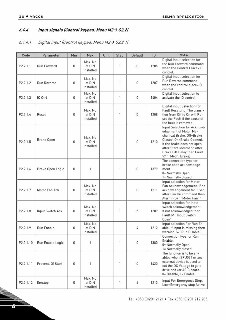
6.4.4 Input signals (Control keypad: Menu M2 G2.2)
6.4.4.1 Digital input (Control keypad: Menu M2 G2.2.1)
Code Parameter Min Max Unit Step Default ID Note
P2.2.1.1 Run Forward 0 Max. No of DIN
installed 1 0 1206
Digital input selection for the Run Forward command when the Control Place=IO control.
P2.2.1.2 Run Reverse 0 Max. No of DIN
installed 1 0 1207
Digital input selection for Run Reverse command when the control place=IO control
P2.2.1.3 IO Ctrl 0 Max. No of DIN
installed 1 0 1404
Digital input selection to activate the IO control.
P2.2.1.4 Reset 0 Max. No of DIN
installed 1 0 1208
Digital input Selection for Fault Resetting. The transi-tion from Off to On will Re-set the Fault if the cause of the fault is removed
P2.2.1.5 Brake Open 0
Max. No of DIN
installed 1 0 1210
Input Selection for Acknowl-edgement of Motor Me-chanical Brake. Off=Brake Closed, On=Brake Opened. If the brake does not open after Start Command after Brake Lift Delay then Fault 57 ``Mech. Brake)
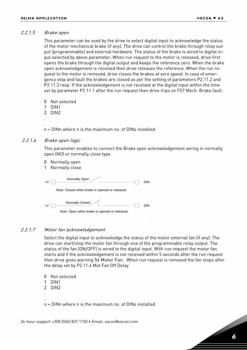
P2.2.1.6 Brake Open Logic 0 1 1 0 1379
The connection type for brake open acknowledge-ment. 0= Normally Open. 1= Normally closed.
P2.2.1.7 Motor Fan Ack. 0 Max. No of DIN
installed 1 0 1211
Input selection for Motor Fan Acknowledgement. If no acknowledgement for 1 Sec after Fan On command then Alarm F56 ``Motor Fan``
P2.2.1.8 Input Switch Ack 0 Max. No of DIN
installed 1 5 1209
Input selection for input switch acknowledgement. If not acknowledged then Fault 64 “Input Switch Open”
P2.2.1.9 Run Enable 0 Max. No of DIN
installed 1 4 1212
Input selection For Run En-able. If input is missing then warning 26 ”Run Disable”.
P2.2.1.10 Run Enable Logic 0 1 1 0 1380
Connection type for Run Enable. 0= Normally Open 1= Normally closed.
P2.2.1.11 Prevent. Of Start 0 1 1 0 1420
The function is to be en-abled when SPU024 or any external device is used to cut the DC Voltage to gate drive and /or ASIC board. 0= Disable, 1= Enable
P2.2.1.12 Emstop 0 Max. No of DIN
installed 1 6 1213 Input For Emergency Stop.
Low=Emergency stop Active

selma application vacon • 21
24-hour support +358 (0)40 837 1150 • Email: [email protected] 6
P2.2.1.13 External Fault 0 Max. No of DIN
installed 1 0 1214
Digital input selection for External Fault signal con-nection.
P2.2.1.14 Ext. Fault Logic 0 0 1 0 1381
Connection type for external fault input connection. 0= Normally open 1= Normally closed.
P2.2.1.15 Motor 1 Or 2 Sel 0 Max. No of DIN
installed 1 0 1215
Select parameter set for Motor 1 or Motor 2 with the selected digital input. High=Motor2.Low=Motor1
P2.2.1.16 Fault Reset 0.1 D.10 TTF 1 0.1 414
P2.2.1.17 Micro start com-mand 0 D.10 1 0 1550
Start command for FB Mode 5 (= Microstar) Rising edge required after fault or Emergency stop. Use OPT-CG Config tool for this ID
P2.2.1.18 Micro stop com-mand
0 D.10 1 0 1551
Stop command for FB Mode 5 (= Microstar) Rising edge required after fault or Emergency stop. Use OPT-CG Config tool for this ID
Table 6. Digital Input parameters, G2.2.1
6.4.4.2 Analogue input (Control keypad: Menu M2 G2.2.2)
Code Parameter Min Max Unit Step Default ID Note
P2.2.2.1 I/O SpeedRef Sel 0 5 1 0 1219 Analogue Input selection for Speed reference when Control Place=1 (IO ctrl)
P2.2.2.2 I/O TorqRef Sel 0 3 1 0 1220
Analoguey Input selection for Torque reference when Control Place=1 (Local IO Control)
P2.2.2.3 PT100(1) AI Sel 0 2 1 0 1221 Analogue Input selection for PT100 type tempera-ture sensor 1.
P2.2.2.4 PT100 (1) Sel 0 2 1 0 1222 No of PT100 elements in series.
P2.2.2.5 PT100(2) AI Sel 0 2 1 0 1223 Analogue Input selection for PT100 type tempera-ture sensor 2.
P2.2.2.6 PT100 (2) Sel 0 2 1 0 1224 No of PT100 elements in series. 0=1*PT100, 1=2*PT100, 2=3*PT100.
P2.2.2.7 AI1 Ref Scale Min -30000 30000 1 0 1226
Min. value of signal se-lected for AI1. This corre-sponds to +0V/0/4mA
P2.2.2.8 AI1 RefScale
Max -30000 30000 1 1440 1225 Max. value of signal se-lected for AI1. This corre-sponds to +10V/20mA
P2.2.2.9 AI1 Minimum 0 1 1 0 1227 Minimum voltage or Cur-rent at AI1.0=0V/0mA, 1=4mA
P2.2.2.10 AI1 Filter Time 0.01 10.00 s 0.01 1 1228 Filter time for AI1 in ###. ## Sec
P2.2.2.11 AI2 RefScale Min -30000 30000 1 0 1230 Min. Value of Signal se-lected for AI2.This corre-sponds to +0V/0/4mA
P2.2.2.12 AI2 RefScale
Max -30000 30000 1 1000 1229 Max. Value of Signal se-lected for AI2.This corre-sponds to +10V/20mA
22 • vacon selma application
Tel. +358 (0)201 2121 • Fax +358 (0)201 212 205 6
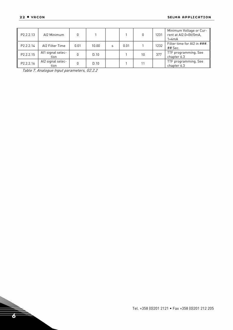
P2.2.2.13 AI2 Minimum 0 1 1 0 1231 Minimum Voltage or Cur-rent at AI2.0=0V/0mA, 1=4mA
P2.2.2.14 AI2 Filter Time 0.01 10.00 s 0.01 1 1232 Filter time for AI2 in ###. ## Sec.
P2.2.2.15 AI1 signal selec-tion
0 D.10 1 10 377 TTF programming. See chapter 6.3
P2.2.2.16 AI2 signal selec-tion
0 D.10 1 11 TTF programming. See chapter 6.3
Table 7. Analogue Input parameters, G2.2.2
selma application vacon • 23
24-hour support +358 (0)40 837 1150 • Email: [email protected] 6
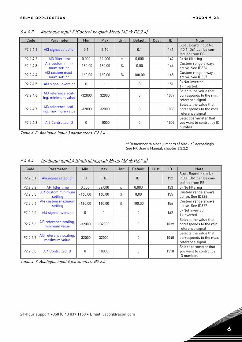
6.4.4.3 Analogue input 3 (Control keypad: Menu M2 G2.2.4)
Code Parameter Min Max Unit Default Cust ID Note
P2.2.4.1 AI3 signal selection 0.1 E.10 0.1
141 Slot . Board input No. If 0.1 ID61 can be con-trolled from FB
P2.2.4.2 AI3 filter time 0,000 32,000 s 0,000 142 0=No filtering
P2.2.4.3 AI3 custom mini-mum setting
-160,00 160,00 % 0,00 144 Custom range always active. See ID326
P2.2.4.4 AI3 custom maxi-mum setting
-160,00 160,00 % 100,00 145 Custom range always active. See ID327
P2.2.4.5 AI3 signal inversion 0 1 0 151 0=Not inverted 1=Inverted
P2.2.4.6 AI3 reference scal-ing, minimum value
-32000 32000 0
1037 Selects the value that corresponds to the min. reference signal
P2.2.4.7 AI3 reference scal-ing, maximum value
-32000 32000 0
1038 Selects the value that corresponds to the max. reference signal
P2.2.4.8 AI3 Controlled ID 0 10000 0
1509 Select parameter that you want to control by ID number.
Table 4-8. Analogue input 3 parameters, G2.2.4
6.4.4.4 Analogue input 4 (Control keypad: Menu M2 G2.2.5)
Code Parameter Min Max Unit Default Cust ID Note
P2.2.5.1 AI4 signal selection 0.1 E.10 0.1
152 Slot . Board input No. If 0.1 ID61 can be con-trolled from FB
P2.2.5.2 AI4 filter time 0,000 32,000 s 0,000 153 0=No filtering
P2.2.5.3 AI4 custom minimum
setting -160,00 160,00 % 0,00
155 Custom range always active. See ID326
P2.2.5.4 AI4 custom maximum
setting -160,00 160,00 % 100,00
156 Custom range always active. See ID327
P2.2.5.5 AI4 signal inversion 0 1 0 162 0=Not inverted 1=Inverted
P2.2.5.6 AI3 reference scaling,
minimum value -32000 -32000 0
1039 Selects the value that corresponds to the min. reference signal
P2.2.5.7 AI3 reference scaling, maximum value
-32000 32000 0
1040 Selects the value that corresponds to the max. reference signal
P2.2.5.8 AI4 Controlled ID 0 10000 0
1510 Select parameter that you want to control by ID number.
Table 4-9. Analogue input 4 parameters, G2.2.5
**Remember to place jumpers of block X2 accordingly. See NX User's Manual, chapter 6.2.2.2
24 • vacon selma application
Tel. +358 (0)201 2121 • Fax +358 (0)201 212 205 6
6.4.5 Output signals (Control keypad: Menu M2 G2.3)
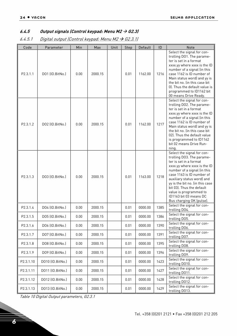
6.4.5.1 Digital output (Control keypad: Menu M2 G2.3.1)
Code Parameter Min Max Unit Step Default ID Note
P2.3.1.1 DO1 (ID.BitNo.) 0.00 2000.15 0.01 1162.00 1216
Select the signal for con-trolling DO1. The parame-ter is set in a format xxxx.yy where xxxx is the ID number of a signal (in this case 1162 is ID number of Main status word) and yy is the bit no. (in this case bit 0). Thus the default value is programmed to ID1162 bit 00 means Drive Ready.
P2.3.1.2 DO2 (ID.BitNo.) 0.00 2000.15 0.01 1162.00 1217
Select the signal for con-trolling DO2. The parame-ter is set in a format xxxx.yy where xxxx is the ID number of a signal (in this case 1162 is ID number of Main status word) and yy is the bit no. (in this case bit 02). Thus the default value is programmed to ID1162 bit 02 means Drive Run-ning.
P2.3.1.3 DO3 (ID.BitNo.) 0.00 2000.15 0.01 1163.00 1218
Select the signal for con-trolling DO3. The parame-ter is set in a format xxxx.yy where xxxx is the ID number of a signal (in this case 1163 is ID number of auxiliary status word) and yy is the bit no. (in this case bit 03). Thus the default value is programmed to ID1163 bit 03 means DC Bus charging OK (pulse).
P2.3.1.4 DO4 (ID.BitNo.) 0.00 2000.15 0.01 0000.00 1385 Select the signal for con-trolling DO4.
P2.3.1.5 DO5 (ID.BitNo.) 0.00 2000.15 0.01 0000.00 1386 Select the signal for con-trolling DO5.
P2.3.1.6 DO6 (ID.BitNo.) 0.00 2000.15 0.01 0000.00 1390 Select the signal for con-trolling DO6.
P2.3.1.7 DO7 (ID.BitNo.) 0.00 2000.15 0.01 0000.00 1391 Select the signal for con-trolling DO7.
P2.3.1.8 DO8 (ID.BitNo.) 0.00 2000.15 0.01 0000.00 1395 Select the signal for con-trolling DO8.
P2.3.1.9 DO9 (ID.BitNo.) 0.00 2000.15 0.01 0000.00 1396 Select the signal for con-trolling DO9.
P2.3.1.10 DO10 (ID.BitNo.) 0.00 2000.15 0.01 0000.00 1423 Select the signal for con-trolling DO10.
P2.3.1.11 DO11 (ID.BitNo.) 0.00 2000.15 0.01 0000.00 1427 Select the signal for con-trolling DO11.
P2.3.1.12 DO12 (ID.BitNo.) 0.00 2000.15 0.01 0000.00 1428 Select the signal for con-trolling DO12.
P2.3.1.13 DO13 (ID.BitNo.) 0.00 2000.15 0.01 0000.00 1429 Select the signal for con-trolling DO13.
Table 10 Digital Output parameters, G2.3.1

selma application vacon • 25
24-hour support +358 (0)40 837 1150 • Email: [email protected] 6
6.4.5.2 Analogue output 1 (Control keypad: Menu M2 G2.3.2)
Code Parameter Min Max Unit Step Default ID Note
P2.3.2.1 AO1 terminal 0 59 1 10 463 TTF programming. See chapter 6.3
P2.3.2.2 AO1 Signal ID 0 2000 1 0 1233 Set the ID no. Of a signal to be connected to AO1.
P2.3.2.3 AO1 Offset 0 1 1 0 1234
Minimum voltage or cur-rent at AO1. 0= OV/0mA. 1= 2v/4mA
P2.3.2.4 AO1 Filter 0.02 10.00 S 0.01 10.00 1235 Filter time for AO1
P2.3.2.5 AO1 Max Value -30000 30000 1 1500 1236
Maximum value of the sig-nal selected for AO1. This will correspond to +10V/ 20mA.
P2.3.2.6 AO1 Min Value -30000 30000 1 0 1237
Minimum value of the sig-nal selected for AO1. This will correspond to 0V/0mA or 2V/4mA depending on AO1 Offset.
Table 11. Analogue output parameters, G2.3.2
6.4.5.3 Analogue output 2 (Control keypad: Menu M2 G2.3.3)
Code Parameter Min Max Unit Step Default ID Note
P2.3.3.1 AO2 terminal 0 59 1 10 471 TTF programming. See chapter 6.3
P2.3.3.2 AO2 Signal ID 0 2000 1 0 1500 Set the ID no. Of a signal to be connected to AO2.
P2.3.3.3 AO2 Offset 0 1 1 0 475
Minimum voltage or cur-rent at AO2. 0= OV/0mA. 1= 2v/4mA
P2.3.3.4 AO2 Filter 0.02 10.00 S 0.01 10.00 472 Filter time for AO2
P2.3.3.5 AO2 Max Value -30000 30000 1 1500 1501
Maximum value of the sig-nal selected for AO2. This will correspond to +10V/ 20mA.
P2.3.3.6 AO2 Min Value -30000 30000 1 0 1502
Minimum value of the sig-nal selected for AO2. This will correspond to 0V/0mA or 2V/4mA depending on AO2 Offset.
Table 12 Analogue output parameters, G2.3.3
26 • vacon selma application
Tel. +358 (0)201 2121 • Fax +358 (0)201 212 205 6
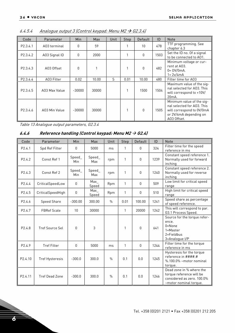
6.4.5.4 Analogue output 3 (Control keypad: Menu M2 G2.3.4)
Code Parameter Min Max Unit Step Default ID Note
P2.3.4.1 AO3 terminal 0 59 1 10 478 TTF programming. See chapter 6.3
P2.3.4.2 AO3 Signal ID 0 2000 1 0 1503 Set the ID no. Of a signal to be connected to AO1.
P2.3.4.3 AO3 Offset 0 1 1 0 482
Minimum voltage or cur-rent at AO3. 0= OV/0mA. 1= 2v/4mA
P2.3.4.4 AO3 Filter 0.02 10.00 S 0.01 10.00 480 Filter time for AO3
P2.3.4.5 AO3 Max Value -30000 30000 1 1500 1504
Maximum value of the sig-nal selected for AO3. This will correspond to +10V/ 20mA.
P2.3.4.6 AO3 Min Value -30000 30000 1 0 1505
Minimum value of the sig-nal selected for AO3. This will correspond to 0V/0mA or 2V/4mA depending on AO3 Offset.
Table 13 Analogue output parameters, G2.3.4
6.4.6 Reference handling (Control keypad: Menu M2 G2.4)
Code Parameter Min Max Unit Step Default ID Note
P2.4.1 Spd Ref Filter 0 5000 ms 1 0 324 Filter time for the speed reference in ms
P2.4.2 Const Ref 1 Speed_Min
Speed_ Max
rpm 1 0 1239 Constant speed reference 1. Normally used for forward inching
P2.4.3 Const Ref 2 Speed_Min
Speed_ Max rpm 1 0 1240
Constant speed reference 2. Normally used for reverse inching
P2.4.4 CriticalSpeedLow 0 Max_ Speed
Rpm 1 0 509 Low limit for critical speed range
P2.4.5 CriticalSpeedHigh 0 Max_ Speed
Rpm 1 0 510 High limit for critical speed range
P2.4.6 Speed Share -300.00 300.00 % 0.01 100.00 1241 Speed share as percentage of speed reference.
P2.4.7 FBRef Scale 10 30000 1 20000 1242 This will correspond to par. G3.1 Process Speed.
P2.4.8 Tref Source Sel 0 3 1 0 641
Source for the torque refer-ence. 0=None 1=Master 2=Fieldbus 3=Analogue I/P
P2.4.9 Tref Filter 0 5000 ms 1 0 1244 Filter time for the torque reference in ms
P2.4.10 Tref Hysteresis -300.0 300.0 % 0.1 0.0 1245
Hysteresis for the torque reference in ####.# %.100.0% ~motor nominal torque.
P2.4.11 Tref Dead Zone -300.0 300.0 % 0.1 0.0 1246
Dead zone in % where the torque reference will be considered as zero. 100.0% ~motor nominal torque.
selma application vacon • 27
24-hour support +358 (0)40 837 1150 • Email: [email protected] 6
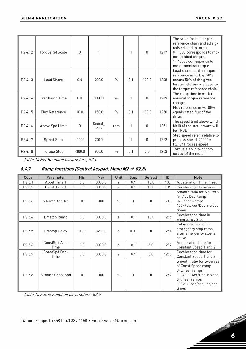
P2.4.12 TorqueRef Scale 0 1 1 0 1247
The scale for the torque reference chain and all sig-nals related to torque. 0= 1000 corresponds to mo-tor nominal torque. 1= 10000 corresponds to motor nominal torque
P2.4.13 Load Share 0.0 400.0 % 0.1 100.0 1248
Load share for the torque reference in %. E.g. 50% means 50% of the given torque reference is used by the torque reference chain.
P2.4.14 Tref Ramp Time 0.0 30000 ms 1 0 1249 The ramp time in ms for nominal torque reference change.
P2.4.15 Flux Reference 10.0 150.0 % 0.1 100.0 1250 Flux reference in %.100% equals rated flux of the drive.
P2.4.16 Above Spd Limit 0 Speed_
Max rpm 1 0 1251 The speed limit above which bit10 of the status word will be TRUE
P2.4.17 Speed Step -2000 2000 1 0 1252 Step speed refer. relative to process speed. 20000 = P2.1.7 Process speed
P2.4.18 Torque Step -300.0 300.0 % 0.1 0.0 1253 Torque step in % of nom. torque of the motor
Table 14 Ref Handling parameters, G2.4
6.4.7 Ramp functions (Control keypad: Menu M2 G2.5)
Code Parameter Min Max Unit Step Default ID Note P2.5.1 Accel Time 1 0.0 3000.0 s 0.1 10.0 103 Acceleration Time in sec P2.5.2 Decel Time 1 0.0 3000.0 s 0.1 10.0 104 Deceleration Time in sec
P2.5.3 S Ramp AccDec 0 100 % 1 0 500
Smooth ratio for S curves for Acc Dec Ramp 0=Linear Ramps 100=Full Acc/Dec inc/dec times.
P2.5.4 Emstop Ramp 0.0 3000.0 s 0.1 10.0 1256 Deceleration time in Emergency Stop
P2.5.5 Emstop Delay 0.00 320.00 s 0.01 0 1254
Delay in activation of emergency stop ramp after emergency stop is active
P2.5.6 ConstSpd Acc-
Time 0.0 3000.0 s 0.1 5.0 1257 Acceleration time for Constant Speed 1 and 2
P2.5.7 ConstSpd Dec-
Time 0.0 3000.0 s 0.1 5.0 1258 Deceleration time for Constant Speed 1 and 2
P2.5.8 S Ramp Const Spd 0 100 % 1 0 1259
Smooth ratio for S-curves of Const Speed ramp 0=Linear ramps 100=Full Acc/Dec inc/dec 0=linear ramps 100=full acc/dec inc/dec times
Table 15 Ramp Function parameters, G2.5

28 • vacon selma application
Tel. +358 (0)201 2121 • Fax +358 (0)201 212 205 6
6.4.8 Drive control (Control keypad: Menu M2 G2.6)
Code Parameter Min Max Unit Step Default ID Note
P2.6.1 Control Place 0 2 1 1 2
125
Place to control the drive operation. 0=FieldBus 1=IO 2=Panel/ PC Tool
P2.6.2 Brake Chopper 0 3 1 0 504
P2.6.3 BrkChopper Level 0 1500 V 1 1.15*nom
DC Volt 1267 Brake chopper operation level in volts
P2.6.4 Brk Res Load Lim 0.0 300.0 % 0.1 5.0 1268
Generator side torque limit to avoid overheating of the brake resistor dur-ing continuous braking. This is active when Brake Chopper is selected and there is no emergency stop active and drive is not decelerating.
P2.6.7 Restart Delay 0.000 60.000 s 0.001 1424 After coast stop the re-starting of the drive is disabled for this time.
P2.6.8 PWM Synch 0 1 1 0 1399
Enables or disables the PWM synchronisation for multiple winding master follower.
Table 16 Drive Control parameters, G2.6
6.4.8.1 Drive control/Open Loop Ctrl (Control keypad: Menu M2 G2.6.5)
Code Parameter Min Max Unit Step Default ID Note
P2.6.5.1 U/f Ratio Select 0 3 1 0 108
U/F ratio selection. 0=Linear 1=Squared 2=Programmable
P2.6.5.2 U/f Zero Point V 0.00 105.00 % 0.01 0.00 606
Motor voltage (%*Motor Nominal Voltage) at pro-grammable U/F curve zero point 10.0 ...105.00 % * MotorNomVoltage
P2.6.5.3 U/f Mid Point V 0.00 105.00 % 0.01 100.00 605
Motor voltage (%*Motor Nominal Voltage) at pro-grammable U/F curve middle point (1000...10500) equals (10.0 ...105.00) % * MotorNomVoltage
P2.6.5.4 U/f Mid Freq 0.00 320.00 Hz 0.01 50.00
604
Programmable U/F curve middle point, f[Hz] = UF-MidPoint/FreqScale Range [0...FieldWeakeningPoint] If FreqScale=100 then 5000 equals 50.00 Hz
P2.6.5.5 U/f Optimiza-
tion 0 1 1 0 109 U/F optimization control
P2.6.5.6 DC Brake
Speed 0 MotorNom
Speed rpm 1 0
515 Below this speed DC brak-ing will be active.
P2.6.5.7 DC Brake Cur-rent
0 Motor Cur-rentMax
A 507
DC Braking current
selma application vacon • 29
24-hour support +358 (0)40 837 1150 • Email: [email protected] 6
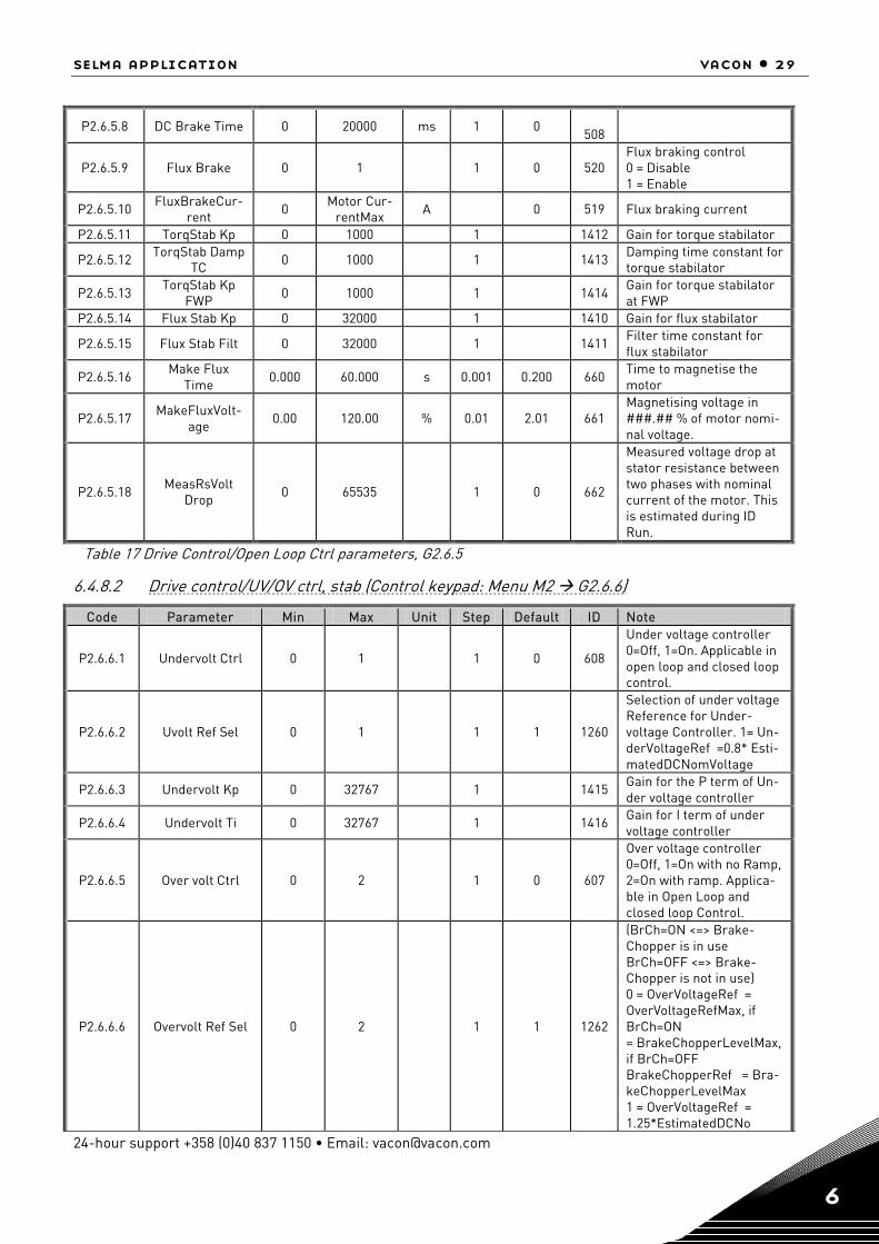
P2.6.5.8 DC Brake Time 0 20000 ms 1 0 508
P2.6.5.9 Flux Brake 0 1 1 0 520 Flux braking control 0 = Disable 1 = Enable
P2.6.5.10 FluxBrakeCur-rent 0 Motor Cur-
rentMax A 0 519 Flux braking current
P2.6.5.11 TorqStab Kp 0 1000 1 1412 Gain for torque stabilator
P2.6.5.12 TorqStab Damp TC 0 1000 1 1413 Damping time constant for
torque stabilator
P2.6.5.13 TorqStab Kp
FWP 0 1000 1 1414 Gain for torque stabilator at FWP
P2.6.5.14 Flux Stab Kp 0 32000 1 1410 Gain for flux stabilator
P2.6.5.15 Flux Stab Filt 0 32000 1 1411 Filter time constant for flux stabilator
P2.6.5.16 Make Flux
Time 0.000 60.000 s 0.001 0.200 660 Time to magnetise the motor
P2.6.5.17 MakeFluxVolt-age
0.00 120.00 % 0.01 2.01 661 Magnetising voltage in ###.## % of motor nomi-nal voltage.
P2.6.5.18 MeasRsVolt Drop 0 65535 1 0 662
Measured voltage drop at stator resistance between two phases with nominal current of the motor. This is estimated during ID Run.
Table 17 Drive Control/Open Loop Ctrl parameters, G2.6.5
6.4.8.2 Drive control/UV/OV ctrl, stab (Control keypad: Menu M2 G2.6.6)
Code Parameter Min Max Unit Step Default ID Note
P2.6.6.1 Undervolt Ctrl 0 1 1 0 608
Under voltage controller 0=Off, 1=On. Applicable in open loop and closed loop control.
P2.6.6.2 Uvolt Ref Sel 0 1 1 1 1260
Selection of under voltage Reference for Under-voltage Controller. 1= Un-derVoltageRef =0.8* Esti-matedDCNomVoltage
P2.6.6.3 Undervolt Kp 0 32767 1 1415 Gain for the P term of Un-der voltage controller
P2.6.6.4 Undervolt Ti 0 32767 1 1416 Gain for I term of under voltage controller
P2.6.6.5 Over volt Ctrl 0 2 1 0 607
Over voltage controller 0=Off, 1=On with no Ramp, 2=On with ramp. Applica-ble in Open Loop and closed loop Control.
P2.6.6.6 Overvolt Ref Sel 0 2 1 1 1262
(BrCh=ON <=> Brake-Chopper is in use BrCh=OFF <=> Brake-Chopper is not in use) 0 = OverVoltageRef = OverVoltageRefMax, if BrCh=ON = BrakeChopperLevelMax, if BrCh=OFF BrakeChopperRef = Bra-keChopperLevelMax 1 = OverVoltageRef = 1.25*EstimatedDCNo

30 • vacon selma application
Tel. +358 (0)201 2121 • Fax +358 (0)201 212 205 6
P2.6.6.7 OverVolt Kp 1468 Gain for P term of over-voltage controller
P2.6.6.8 OverVolt Kp Add 1425 Addition gain for P term of overvoltage controller till FWP.
P2.6.6.9 OverVolt Ti 1409 Gain for I term of the over-voltage controller.
P2.6.6.10 VoltStab Kp 1417 Gain for the voltage stabi-lator
P2.6.6.11 VoltStab TC 1418 Damping rate for the volt-age stabilator.
Table 18. Drive Control/UV/OV Ctrl, Stab Parameters, G2.6.6
6.4.9 Motor control (Control keypad: Menu M2 G2.7)
Code Parameter Min Max Unit Step Default ID Note
P2.7.1 Start Function 0 1 1 0 505 0=Starts from 0-speed, 1=Flying start
P2.7.2 Stop Function 0 1 1 0 506 0=Coast stop 1=Ramp stop
P2.7.3 Emstop Mode 0 3 1 1 1276
Stop function in Emer-gency Stop 0=Coast Stop 1=Ramp stop 2=Torque limit Stop 3=Constant Power Stop
P2.7.4 Motor Ctrl Mode 0 5 1 0 600
0=Open Loop Freq ctrl, 1=Open Loop Speed crtl 2=Open Loop Torque crtl 3=Closed Loop speed/ torque Control as per P2.7.5 4=AOL Speed Control 5=AOL Torque Control
P2.7.5 Torque Select 1 5 1 1 1278
1=Speed Control 2=Torque Control 3=Min of torque ref and SPC Out 4=Max of torque ref and SPC Out 5=Window Control
P2.7.6 CurrentControlKp 1 10000 1 4000 617 Current controller p-gain (0 ... 10000)
P2.7.7 CurrentControlTi 0.1 100.0 ms 0.1 1.5 1400 Current controller inte-grator time constant (0 ... 1000) = 0...100.0 ms
P2.7.8 Switching Freq 1.0 Switching FreqMax
KHz 0.1 601 Switching frequency.
P2.7.9 Dynamic Damp Kp 0.00 100.00 % 0.01 0 1406
Dynamic damping gain when parameter 2.7.5 Torque Select is greater than 1. 1.00 means nomi-nal torque for nominal speed difference.
P2.7.10 Dynamic Damp TC 0 32000 ms 1 0 1407
Bandpass filter time con-stant for dynamic damp-ing. 0 means static damp-ing proportional to fre-quency error.
P2.7.11 DC Magn Current 0.0 Motor Nom
Current A 627 Constant DC Magnetiza-
tion Current

selma application vacon • 31
24-hour support +358 (0)40 837 1150 • Email: [email protected] 6
Code Parameter Min Max Unit Step Default ID Note
P2.7.12 DC Magn Time 0 10000 ms 1 0 628 Constant DC magn. time [ms] in ramp start
P2.7.13 Start 0Speed Time 0 32000 ms 1 100 615 Time of zero speed ref at start in ms, (0 ...32000)
P2.7.14 Stop 0SpeedTime 0 32000 ms 1 100 616 Time of zero speed ref at ramp stop in ms, (0 ...32000)
P2.7.15 Stop State Flux 0 150.0 % 1 100.0 1401
The % of rated flux main-tained after the motor is stopped for the time Flux Off Delay.
P2.7.16 Flux Off Delay -1 32000 s 1 0 1402
The time in seconds for which the flux will be maintained in the motor. Setting this value to –1 will keep the Stop State Flux continuously.
Table 19. Motor control parameters, G2.7
6.4.9.1 PMSM Control (Control keypad: Menu M2 G2.7.17)
Code Parameter Min Max Unit Step Default ID Note
P2.7.17.1 Flux Control Kp 0.00 320.00 % 0.01 5.00 651 Gain for the flux control-ler in %.
P2.7.17.2 Flux Control Ti 0.0 100.0 ms 0.1 5.0 652 Integral time constant for flux current controller in ms.
P2.7.17.3 RsIdentification 0 1 1 0 654
Stator resisatnce identifi-cation during every start. 0= Disabled 1=Enabled.
P2.7.17.4 Modulation Index 0 200 % 1 100 655 Modulation index in % for closed loop operation.
P2.7.17.5 EncAngleOffset 0 65535 1 0 649
Low word of (endat) en-coder angle correspond-ing to shaft 0 position. This parameter is only for monitoring and back up purpose. It is used only with absolute encoders .
Table 20. PMSM control parameters, G2.7.17

32 • vacon selma application
Tel. +358 (0)201 2121 • Fax +358 (0)201 212 205 6
6.4.10 Limit settings (Control keypad: Menu M2 G2.8)
Code Parameter Min Max Unit Step Default ID Note
P2.8.1 Zero Speed Level 0 Motor NomSpeed
rpm 1 15 1283 Speed below which Bit 11 of Auxiliary Status Word becomes TRUE
P2.8.2 Zero Speed Mon 0 1 1 1 1284 Monitoring of Zero speed is based on 0=Speed Ref, 1=Speed Actual
P2.8.3 Speed Maximum -10000 10000 rpm 1 1440 1285 Maximum limit of the Speed reference
P2.8.4 Speed Minimum -10000 10000 rpm 1 0 1286 Minimum Limit for the Speed Reference
P2.8.5 Current Limit Motor Cur-
rentMin
Motor CurrMax A 0.1 107
Maximum Total Current Limit.
P2.8.6 Torque Limit Mot 0.0 300.0 % 0.1 300.0 1287 Torque limit for the mo-toring side.
P2.8.7 Torque Limit Gen 0.0 300.0 % 0.1 300.0 1288 Torque limit for the gen-erator side.
P2.8.8 SPC OUT Limit 0.0 300.0 % 0.1 300.0 1382
Absolute maximum limit for the speed controller output in closed loop con-trol in % of motor nomi-nal torque.
P2.8.9 Power Limit Mot 0.0 300.0 % 0.1 300.0 1289 Power limit for motor side
P2.8.10 Power Limit Gen 0.0 300.0 % 0.1 300.0 1290 Power limit for generator side
P2.8.11 PullOutTorque 0.0 1000.0 % 0.1 250.0 1291 Pull Out Torque limit of the motor
P2.8.12 System Inertia 0 30000 kgm2 1 0 1292 Inertia of the system in kgm2.
P2.8.13 Max Brake Power 0.000 30.000 kW 0.001 0.000 1293
Max Braking Power Limit in Constant Power Emer-gency Stop
P2.8.14 Max Braking Torq 1 30000 Nm 1 1 1294 Max Braking Torque of the motor in Constant Power Emergency Stop
Table 21 Limit setting parameters, G2.8
selma application vacon • 33
24-hour support +358 (0)40 837 1150 • Email: [email protected] 6
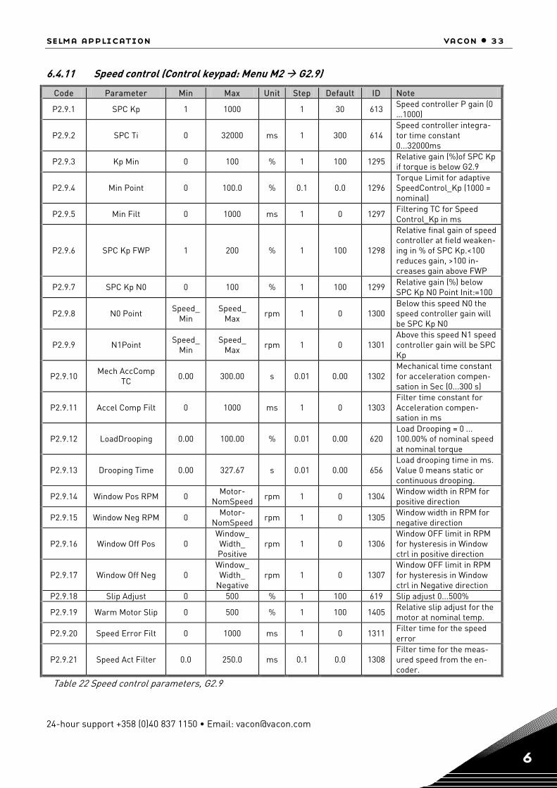
6.4.11 Speed control (Control keypad: Menu M2 G2.9)
Code Parameter Min Max Unit Step Default ID Note
P2.9.1 SPC Kp 1 1000 1 30 613 Speed controller P gain (0 …1000)
P2.9.2 SPC Ti 0 32000 ms 1 300 614 Speed controller integra-tor time constant 0...32000ms
P2.9.3 Kp Min 0 100 % 1 100 1295 Relative gain (%)of SPC Kp if torque is below G2.9
P2.9.4 Min Point 0 100.0 % 0.1 0.0 1296 Torque Limit for adaptive SpeedControl_Kp (1000 = nominal)
P2.9.5 Min Filt 0 1000 ms 1 0 1297 Filtering TC for Speed Control_Kp in ms
P2.9.6 SPC Kp FWP 1 200 % 1 100 1298
Relative final gain of speed controller at field weaken-ing in % of SPC Kp.<100 reduces gain, >100 in-creases gain above FWP
P2.9.7 SPC Kp N0 0 100 % 1 100 1299 Relative gain (%) below SPC Kp N0 Point Init:=100
P2.9.8 N0 Point Speed_ Min
Speed_ Max
rpm 1 0 1300 Below this speed N0 the speed controller gain will be SPC Kp N0
P2.9.9 N1Point Speed_Min
Speed_ Max
rpm 1 0 1301 Above this speed N1 speed controller gain will be SPC Kp
P2.9.10 Mech AccComp
TC 0.00 300.00 s 0.01 0.00 1302 Mechanical time constant for acceleration compen-sation in Sec (0...300 s)
P2.9.11 Accel Comp Filt 0 1000 ms 1 0 1303 Filter time constant for Acceleration compen-sation in ms
P2.9.12 LoadDrooping 0.00 100.00 % 0.01 0.00 620 Load Drooping = 0 ... 100.00% of nominal speed at nominal torque
P2.9.13 Drooping Time 0.00 327.67 s 0.01 0.00 656 Load drooping time in ms. Value 0 means static or continuous drooping.
P2.9.14 Window Pos RPM 0 Motor-NomSpeed
rpm 1 0 1304 Window width in RPM for positive direction
P2.9.15 Window Neg RPM 0 Motor-NomSpeed
rpm 1 0 1305 Window width in RPM for negative direction
P2.9.16 Window Off Pos 0 Window_ Width_ Positive
rpm 1 0 1306 Window OFF limit in RPM for hysteresis in Window ctrl in positive direction
P2.9.17 Window Off Neg 0 Window_ Width_
Negative rpm 1 0 1307
Window OFF limit in RPM for hysteresis in Window ctrl in Negative direction
P2.9.18 Slip Adjust 0 500 % 1 100 619 Slip adjust 0...500%
P2.9.19 Warm Motor Slip 0 500 % 1 100 1405 Relative slip adjust for the motor at nominal temp.
P2.9.20 Speed Error Filt 0 1000 ms 1 0 1311 Filter time for the speed error
P2.9.21 Speed Act Filter 0.0 250.0 ms 0.1 0.0 1308 Filter time for the meas-ured speed from the en-coder.
Table 22 Speed control parameters, G2.9
34 • vacon selma application
Tel. +358 (0)201 2121 • Fax +358 (0)201 212 205 6
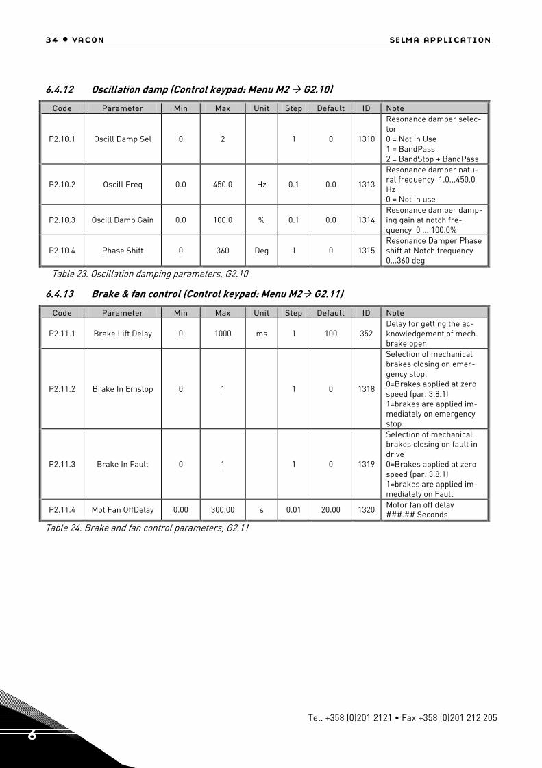
6.4.12 Oscillation damp (Control keypad: Menu M2 G2.10)
Code Parameter Min Max Unit Step Default ID Note
P2.10.1 Oscill Damp Sel 0 2 1 0 1310
Resonance damper selec-tor 0 = Not in Use 1 = BandPass 2 = BandStop + BandPass
P2.10.2 Oscill Freq 0.0 450.0 Hz 0.1 0.0 1313
Resonance damper natu-ral frequency 1.0...450.0 Hz 0 = Not in use
P2.10.3 Oscill Damp Gain 0.0 100.0 % 0.1 0.0 1314 Resonance damper damp-ing gain at notch fre-quency 0 ... 100.0%
P2.10.4 Phase Shift 0 360 Deg 1 0 1315 Resonance Damper Phase shift at Notch frequency 0...360 deg
Table 23. Oscillation damping parameters, G2.10
6.4.13 Brake & fan control (Control keypad: Menu M2 G2.11)
Code Parameter Min Max Unit Step Default ID Note
P2.11.1 Brake Lift Delay 0 1000 ms 1 100 352 Delay for getting the ac-knowledgement of mech. brake open
P2.11.2 Brake In Emstop 0 1 1 0 1318
Selection of mechanical brakes closing on emer-gency stop. 0=Brakes applied at zero speed (par. 3.8.1) 1=brakes are applied im-mediately on emergency stop
P2.11.3 Brake In Fault 0 1 1 0 1319
Selection of mechanical brakes closing on fault in drive 0=Brakes applied at zero speed (par. 3.8.1) 1=brakes are applied im-mediately on Fault
P2.11.4 Mot Fan OffDelay 0.00 300.00 s 0.01 20.00 1320 Motor fan off delay ###.## Seconds
Table 24. Brake and fan control parameters, G2.11
selma application vacon • 35
24-hour support +358 (0)40 837 1150 • Email: [email protected] 6
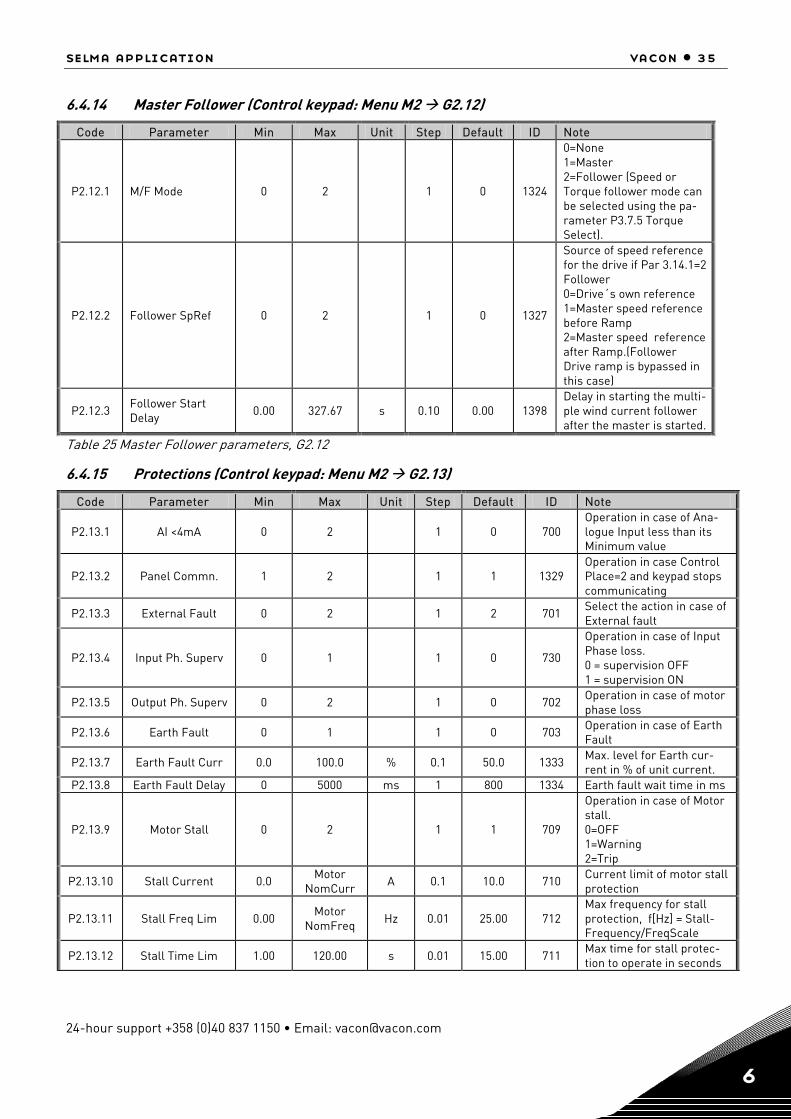
6.4.14 Master Follower (Control keypad: Menu M2 G2.12)
Code Parameter Min Max Unit Step Default ID Note
P2.12.1 M/F Mode 0 2 1 0 1324
0=None 1=Master 2=Follower (Speed or Torque follower mode can be selected using the pa-rameter P3.7.5 Torque Select).
P2.12.2 Follower SpRef 0 2 1 0 1327
Source of speed reference for the drive if Par 3.14.1=2 Follower 0=Drive´s own reference 1=Master speed reference before Ramp 2=Master speed reference after Ramp.(Follower Drive ramp is bypassed in this case)
P2.12.3 Follower Start Delay 0.00 327.67 s 0.10 0.00 1398
Delay in starting the multi-ple wind current follower after the master is started.
Table 25 Master Follower parameters, G2.12
6.4.15 Protections (Control keypad: Menu M2 G2.13)
Code Parameter Min Max Unit Step Default ID Note
P2.13.1 AI <4mA 0 2 1 0 700 Operation in case of Ana-logue Input less than its Minimum value
P2.13.2 Panel Commn. 1 2 1 1 1329 Operation in case Control Place=2 and keypad stops communicating
P2.13.3 External Fault 0 2 1 2 701 Select the action in case of External fault
P2.13.4 Input Ph. Superv 0 1 1 0 730
Operation in case of Input Phase loss. 0 = supervision OFF 1 = supervision ON
P2.13.5 Output Ph. Superv 0 2 1 0 702 Operation in case of motor phase loss
P2.13.6 Earth Fault 0 1 1 0 703 Operation in case of Earth Fault
P2.13.7 Earth Fault Curr 0.0 100.0 % 0.1 50.0 1333 Max. level for Earth cur-rent in % of unit current.
P2.13.8 Earth Fault Delay 0 5000 ms 1 800 1334 Earth fault wait time in ms
P2.13.9 Motor Stall 0 2 1 1 709
Operation in case of Motor stall. 0=OFF 1=Warning 2=Trip
P2.13.10 Stall Current 0.0 Motor NomCurr
A 0.1 10.0 710 Current limit of motor stall protection
P2.13.11 Stall Freq Lim 0.00 Motor
NomFreq Hz 0.01 25.00 712 Max frequency for stall protection, f[Hz] = Stall-Frequency/FreqScale
P2.13.12 Stall Time Lim 1.00 120.00 s 0.01 15.00 711 Max time for stall protec-tion to operate in seconds
36 • vacon selma application
Tel. +358 (0)201 2121 • Fax +358 (0)201 212 205 6
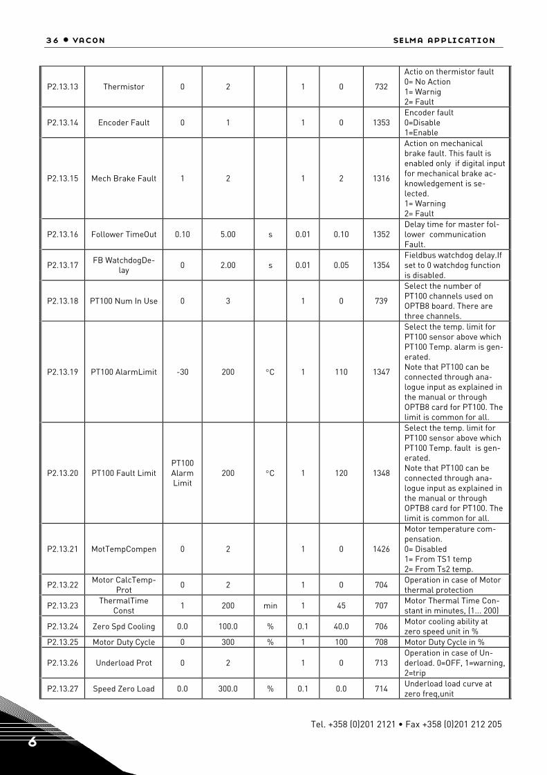
P2.13.13 Thermistor 0 2 1 0 732
Actio on thermistor fault 0= No Action 1= Warnig 2= Fault
P2.13.14 Encoder Fault 0 1 1 0 1353 Encoder fault 0=Disable 1=Enable
P2.13.15 Mech Brake Fault 1 2 1 2 1316
Action on mechanical brake fault. This fault is enabled only if digital input for mechanical brake ac-knowledgement is se-lected. 1= Warning 2= Fault
P2.13.16 Follower TimeOut 0.10 5.00 s 0.01 0.10 1352 Delay time for master fol-lower communication Fault.
P2.13.17 FB WatchdogDe-lay 0 2.00 s 0.01 0.05 1354
Fieldbus watchdog delay.If set to 0 watchdog function is disabled.
P2.13.18 PT100 Num In Use 0 3 1 0 739
Select the number of PT100 channels used on OPTB8 board. There are three channels.
P2.13.19 PT100 AlarmLimit -30 200 °C 1 110 1347
Select the temp. limit for PT100 sensor above which PT100 Temp. alarm is gen-erated. Note that PT100 can be connected through ana-logue input as explained in the manual or through OPTB8 card for PT100. The limit is common for all.
P2.13.20 PT100 Fault Limit PT100 Alarm Limit
200 °C 1 120 1348
Select the temp. limit for PT100 sensor above which PT100 Temp. fault is gen-erated. Note that PT100 can be connected through ana-logue input as explained in the manual or through OPTB8 card for PT100. The limit is common for all.
P2.13.21 MotTempCompen 0 2 1 0 1426
Motor temperature com-pensation. 0= Disabled 1= From TS1 temp 2= From Ts2 temp.
P2.13.22 Motor CalcTemp-Prot
0 2 1 0 704 Operation in case of Motor thermal protection
P2.13.23 ThermalTime Const 1 200 min 1 45 707 Motor Thermal Time Con-
stant in minutes, (1... 200)
P2.13.24 Zero Spd Cooling 0.0 100.0 % 0.1 40.0 706 Motor cooling ability at zero speed unit in %
P2.13.25 Motor Duty Cycle 0 300 % 1 100 708 Motor Duty Cycle in %
P2.13.26 Underload Prot 0 2 1 0 713 Operation in case of Un-derload. 0=OFF, 1=warning, 2=trip
P2.13.27 Speed Zero Load 0.0 300.0 % 0.1 0.0 714 Underload load curve at zero freq,unit

selma application vacon • 37
24-hour support +358 (0)40 837 1150 • Email: [email protected] 6
P2.13.28 Speed Nom Load 0.0 300.0 % 0.1 0.0 1341 Underload load curve at nominal freq,unit
P2.13.29 UnderLdSpeed Nom 0
Motor Nom-
SpeedMax rpm 1 1440 1342 Speed limit value for Un-
derload protection
Table 26. Protection parameters, G2.13
6.4.16 Flux reference handling (Control keypad: Menu M2 G2.14)
Code Parameter Min Max Unit Step Default ID Note P2.14.1 Flux Curve 10% 0.0 200.0 % 0.1 10.0 1355 Flux linearisation point 1 P2.14.2 Flux Curve 20% 0.0 200.0 % 0.1 20.0 1356 Flux linearisation point 2 P2.14.3 Flux Curve 30% 0.0 200.0 % 0.1 30.0 1357 Flux linearisation point 3 P2.14.4 Flux Curve 40% 0.0 200.0 % 0.1 40.0 1358 Flux linearisation point 4 P2.14.5 Flux Curve 50% 0.0 200.0 % 0.1 50.0 1359 Flux linearisation point 5 P2.14.6 Flux Curve 60% 0.0 200.0 % 0.1 60.0 1360 Flux linearisation point 6 P2.14.7 Flux Curve 70% 0.0 200.0 % 0.1 70.0 1361 Flux linearization point 7 P2.14.8 Flux Curve 80% 0.0 200.0 % 0.1 80.0 1362 Flux linearization point 8 P2.14.9 Flux Curve 90% 0.0 200.0 % 0.1 90.0 1363 Flux linearization point 9
P2.14.10 Flux Curve 100% 0.0 200.0 % 0.1 100.0 1364 Flux linearization point 10 P2.14.11 Flux Curve 110% 0.0 200.0 % 0.1 110.0 1365 Flux linearization point 11 P2.14.12 Flux Curve 120% 0.0 200.0 % 0.1 120.0 1366 Flux linearization point 12 P2.14.13 Flux Curve 130% 0.0 200.0 % 0.1 130.0 1367 Flux linearization point 13 P2.14.14 Flux Curve 140% 0.0 200.0 % 0.1 140.0 1368 Flux linearization point 14 P2.14.15 Flux Curve 150% 0.0 200.0 % 0.1 150.0 1369 Flux linearization point 15
Table 27. Flux reference handling parameters, G2.14
6.4.17 Startup torque (Control keypad: Menu M2 G2.15)
Code Parameter Min Max Unit Step Default ID Note
P2.15.1 Startup TorqueSel 0 3 1 0 621
0 = Not in use 1 = Torque Memory, 2 = Torque Reference 3 = Startup Torque FWD/REV
P2.15.2 Startup Torq Time 0 10000 ms 1 0 1371 Maximum time for startup torque in ms, (0 ...10000)
P2.15.3 Startup Torq FWD -300.0 300.0 % 0.1 0.0 633
StartupTorqueReference to forward direction -300.0 ...300.0% of motor nominal torque
P2.15.4 Startup Torq REV -300.0 300.0 % 0.1 0.0 634 StartupTorqueReference to reverse direction -300.0 ...300.0%.
P2.15.5 Torq Memory Srce 0 2 1 1 1374
Source for torque mem-ory. At the next start the same startup torque ref-erence will be used.
P2.15.6 Torq Memory Ref -300.0 300.0 % 0.1 0.0 1375 Fixed reference for the torque memory
Table 28. Start-up Torque parameters, G2.15

38 • vacon selma application
Tel. +358 (0)201 2121 • Fax +358 (0)201 212 205 6
6.4.18 DAC (Control keypad: Menu M2 G2.16)
Code Parameter Min Max Unit Step Default ID Note
P2.16.1 Speed Mon Filter 20 2000 ms 1 20 1376 Filter in ms for monitoring signal V1.1.2 Motor Speed.
P2.16.2 Curr Mon Filter 20 2000 ms 1 20 1377 Filter in ms for monitoring signal V1.1.4 Motor Curr
P2.16.3 Torq Mon Filter 20 2000 ms 1 20 1378 Filter in ms for monitoring signal V1.1.5 Motor Torque
Table 29 DAC parameters, PG.16
6.4.19 Data mapping (Control keypad: Menu M2 G2.17)
Code Parameter Min Max Unit Step Default ID Note P2.17.1 PD IN1 ID 0 65535 1 0 876 P2.17.2 PD IN2 ID 0 65535 1 0 877 P2.17.3 PD IN3 ID 0 65535 1 0 878 P2.17.4 PD IN4 ID 0 65535 1 0 879 P2.17.5 PD IN5 ID 0 65535 1 0 880 P2.17.6 PD IN6 ID 0 65535 1 0 881 P2.17.7 PD IN7 ID 0 65535 1 0 882 P2.17.8 PD IN8 ID 0 65535 1 0 883 P2.17.9 PD OUT1 ID 0 65535 1 4 852 Torque
P2.17.10 PD OUT2 ID 0 65535 1 1163 853 Aux Control Word P2.17.11 PD OUT3 ID 0 65535 1 1172 854 Fault Word 1 P2.17.12 PD OUT4 ID 0 65535 1 1173 855 Fault Word 2 P2.17.13 PD OUT5 ID 0 65535 1 15 856 DIN Status Word 1 P2.17.14 PD OUT6 ID 0 65535 1 1174 857 Alarm Word P2.17.15 PD OUT7 ID 0 65535 1 1170 858 Motor Shaft Rounds P2.17.16 PD OUT8 ID 0 65535 1 1169 859 Motor Shaft Position
P2.17.17 FB Mode 1 5 4 896
1= Profidrive mode 2= Bypass mode 3= Not used 4= Selma mode 5= MicroStar mode
Table 30. Data mapping parameters, G2.17
6.4.20 Keypad control (Control keypad: Menu M3 R3.1)
The reference from the keypad when control place is selected as keypad is listed below. See the Key-pad control menu in the product's User's Manual.
Code Parameter Min Max Unit Step Default ID Note
R2.1 Keypad reference P2.8.4 Speed
Min
P2.8.3 Speed Max
rpm 1 Local speed reference in rpm when control place is keypad.
Table 31. Keypad control parameters, M3
6.4.21 Expander boards (Control keypad: Menu M7)
The M7 menu shows the expander and option boards attached to the control board and board-related information. For more information, see the product's User's Manual.
selma application vacon • 39
24-hour support +358 (0)40 837 1150 • Email: [email protected] 6
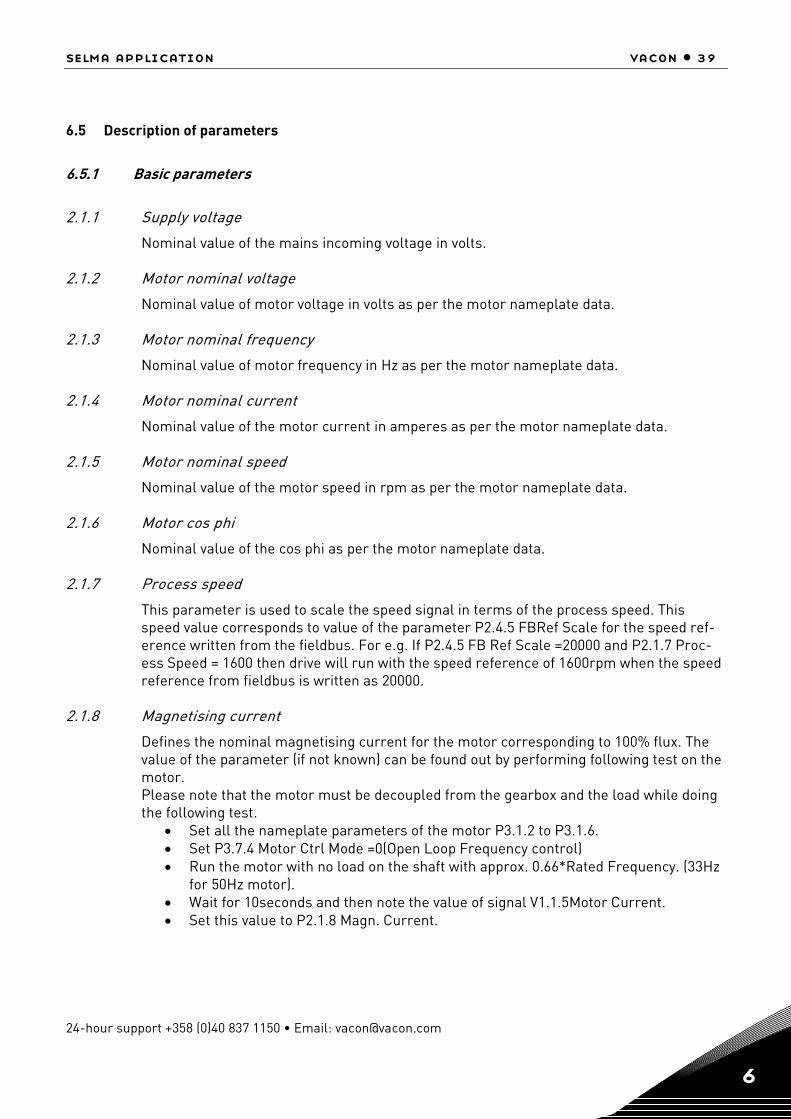
6.5 Description of parameters
6.5.1 Basic parameters
2.1.1 Supply voltage
Nominal value of the mains incoming voltage in volts.
2.1.2 Motor nominal voltage
Nominal value of motor voltage in volts as per the motor nameplate data.
2.1.3 Motor nominal frequency
Nominal value of motor frequency in Hz as per the motor nameplate data. 2.1.4 Motor nominal current
Nominal value of the motor current in amperes as per the motor nameplate data. 2.1.5 Motor nominal speed
Nominal value of the motor speed in rpm as per the motor nameplate data.
2.1.6 Motor cos phi
Nominal value of the cos phi as per the motor nameplate data.
2.1.7 Process speed
This parameter is used to scale the speed signal in terms of the process speed. This speed value corresponds to value of the parameter P2.4.5 FBRef Scale for the speed ref-erence written from the fieldbus. For e.g. If P2.4.5 FB Ref Scale =20000 and P2.1.7 Proc-ess Speed = 1600 then drive will run with the speed reference of 1600rpm when the speed reference from fieldbus is written as 20000.
2.1.8 Magnetising current
Defines the nominal magnetising current for the motor corresponding to 100% flux. The value of the parameter (if not known) can be found out by performing following test on the motor. Please note that the motor must be decoupled from the gearbox and the load while doing the following test.
• Set all the nameplate parameters of the motor P3.1.2 to P3.1.6. • Set P3.7.4 Motor Ctrl Mode =0(Open Loop Frequency control) • Run the motor with no load on the shaft with approx. 0.66*Rated Frequency. (33Hz
for 50Hz motor). • Wait for 10seconds and then note the value of signal V1.1.5Motor Current. • Set this value to P2.1.8 Magn. Current.

40 • vacon selma application
Tel. +358 (0)201 2121 • Fax +358 (0)201 212 205 6
2.1.9 Field weakening point
The field weakening point is the output frequency at which the motor voltage reaches the value of P2.1.10 Voltage at FWP in percentage. This parameter is applicable during open loop control of the motor. Normally this parameter is set equal to motor nominal fre-quency.
2.1.10 Voltage at field weakening point
Percentage value of the motor voltage at the field weakening point defined by P2.1.9. Above the field weakening point frequency the voltage remains to the value set by this pa-rameter. This parameter is applicable during open loop control of the motor. Normally this parameter is set to 100.00% of motor nominal voltage.
2.1.11 Identification run
This parameter defines the different modes of the automatic motor identification run. Set the parameter and give the run command within 20 seconds to activate the identification. The result of the identification is seen in V1.1.19 ID Run Status. The parameter is reset to zero (None) after the identification is complete. In case of failure Alarm 57 ID Run Fail is generated. 0 None 1 Identification without motor running The identification is performed with motor at standstill. In this mode motor stator re-
sistance and parameters for U/F curve are identified. At the end of the identification the parameter P2.6.5.1 U/f Ratio Select is set equal to 2 (programmable). This identifica-tion mode is used when it is not possible to decouple the motor from the gearbox and load. The identification optimises the performance for open loop motor control mode i.e. P2.7.4 = 0/1/2.
After the successful identification B0 of variable ID Run Status is Set.
2 Identification with motor running The identification is performed with motor running. It is recommended to decouple the
motor from the gearbox and the load. In addition to the motor parameters for open loop motor control, magnetising current (P2.1.8) and flux linearization curve (P2.14.1 to P2.14.15) are identified.
After the successful identification B0, B2 and B3 of variable ID Run Status is Set.
3 Encoder ID The motor may rotate during the identification. The function is primarily used to iden-
tify the shaft zero position for PMSM motor when absolute encoder is used.
4 Magnetisation current calculation In this identification, the magnetisation current of the motor for a given motor data
(P2.1.2…P2.1.6) is calculated. Note: The motor is not subjected to any voltage or cur-rent. Giving a run command.

selma application vacon • 41
24-hour support +358 (0)40 837 1150 • Email: [email protected] 6
2.1.12 Motor type
This parameter defines the type of the motor connected to the frequency converter. It is possible to connect the following motor types to VACON NXP frequency converters.
0 Normal Induction motor 1 Multiple winding induction motor Motors with multiple and galvanically isolated phase windings. 2 Permanent magnet induction motor 3 Multiple winding permanent magnet induction motor.
Note: Please consult with Vacon technical support to use options 1...3.

42 • vacon selma application
Tel. +358 (0)201 2121 • Fax +358 (0)201 212 205 6
6.5.2 Input signals
6.5.2.1 Digital input
2.2.1.1 Run forward
Select the digital input for starting the motor when P3.6.1 Control Place =1 (I/O). Drive starts running when digital is high and it stops when low.
0 Not selected 1 DIN1 2 DIN2 . . n = DINn where n is the maximum no. of DINs installed.
2.2.1.2 Run reverse
Select the digital input for reversing the direction of the motor when P3.6.1 Control Place=1 (I/O). The motor runs with positive speed reference when selected digital input is low and with negative reference when high.
0 Not selected 1 DIN1 2 DIN2 . . n = DINn where n is the maximum no. of DINs installed.
2.2.1.3 IO control
Select the condition to be able to control the drive from IO i.e. P2.6.1 Control Place = 1(I/O).
0 Not selected 1 DIN1 2 DIN2 . . n = DINn where n is the maximum no. of DINs installed.
2.2.1.4 Reset
Select the digital input for resetting the drive fault. The rising edge of the digital input re-sets the fault if the cause of the fault is disappeared.
0 Not selected 1 DIN1 2 DIN2 . . n = DINn where n is the maximum no. of DINs installed.
selma application vacon • 43
24-hour support +358 (0)40 837 1150 • Email: [email protected] 6
2.2.1.5 Brake open
This parameter can be used by the drive to select digital input to acknowledge the status of the motor mechanical brake (if any). The drive can control the brake through relay out-put (programmable) and external hardware. The status of the brake is wired to digital in-put selected by above parameter. When run request to the motor is released, drive first opens the brake through the digital output and keeps the reference zero. When the brake open acknowledgement is received then drive releases the reference. When the run re-quest to the motor is removed, drive closes the brakes at zero speed. In case of emer-gency stop and fault the brakes are closed as per the setting of parameters P2.11.2 and P2.11.3 resp. If the acknowledgement is not received at the digital input within the time set by parameter P2.11.1 after the run request then drive trips on F57 Mech. Brake fault. 0 Not selected 1 DIN1 2 DIN2 . . n = DINn where n is the maximum no. of DINs installed.
2.2.1.6 Brake open logic
This parameter enables to connect the Brake open acknowledgement wiring in normally open (NO) or normally close type.
0 Normally open 1 Normally close
DINNormally Open
+V
Note: Closed when brake is opened or released.
DINNormally Closed
+V
Note: Open when brake is opened or released.
2.2.1.7 Motor fan acknowledgement
Select the digital input to acknowledge the status of the motor external fan (if any). The drive can start/stop the motor fan through one of the programmable relay output. The status of the fan (ON/OFF) is wired to the digital input. With run request the motor fan starts and if the acknowledgement is not received within 5 seconds after the run request then drive gives warning 56 Motor Fan. When run request is removed the fan stops after the delay set by P2.11.4 Mot Fan Off Delay. 0 Not selected 1 DIN1 2 DIN2 . . n = DINn where n is the maximum no. of DINs installed.

44 • vacon selma application
Tel. +358 (0)201 2121 • Fax +358 (0)201 212 205 6
2.2.1.8 Input switch acknowledgewment
Select the digital input to acknowledge the status of input switch. The input switch is nor-mally switch fuse unit or main contactor with which the power is fed to the drive. If the in-put switch acknowledgement is missing, drive trips on “ F64 Input Switch open” fault. 0 Not selected 1 DIN1 2 DIN2 . . n = DINn where n is the maximum no. of DINs installed.
2.2.1.9 Run enable
Select the digital input to activate the Run Enable input to the drive. When run Enable is low, the drive coasts to stop with “OFF” indication on the keypad and “F26 Run Disable” warning. Normally the motor load switch or prevention of false start relay status is used as Run Enable. 0 Not selected 1 DIN1 2 DIN2 . . n = DINn where n is the maximum no. of DINs installed.
2.2.1.10 Run enable logic
This parameter enables to connect the Run Enable wiring in normally open (NO) or nor-mally close type. 0 Normally open 1 Normally close
DINNormally Open
+V
Note: Run Enabled when closed.
DINNormally Closed
+V
Note: Run Enabled when Open.

selma application vacon • 45
24-hour support +358 (0)40 837 1150 • Email: [email protected] 6
2.2.1.11 Prevention of start
This parameter is enabled when external device like SPU-024 is used for cutting the power supply to the gate driver and or ASIC board to activate the prevention of false start circuit. This is a safety function and is used to ensure the safety of personnel working in the process during the maintenance. Please note that during the maintenance of the drive the main power has to be switched off. 0 Enable 1 Disable When this function is enabled and Run Enable is low the alarm F26 Prevention of start is activated. Note: The DC bus voltage and Unit temperature measurements are not active during Pre-vention of start. Also the analogue input measurements are not active.
2.2.1.12 Emergency stop
Select the digital input to activate the emergency stop input to the drive. When digital in-put is low the drive stops as per the parameter definition of P3.7.3 Emergency stop mode. 0 Not selected 1 DIN1 2 DIN2 . . n = DINn where n is the maximum no. of DINs installed.
2.2.1.13 External fault
Select the digital input to activate the external fault in the drive. When the selected digital input is high the drive trips on F51External fault and coasts to stop. 0 Not selected 1 DIN1 2 DIN2 . . n = DINn where n is the maximum no. of DINs installed.
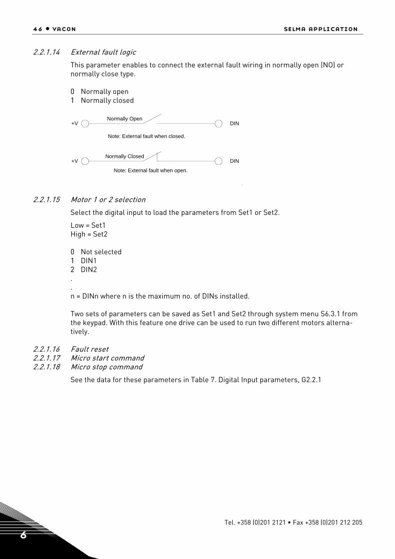
46 • vacon selma application
Tel. +358 (0)201 2121 • Fax +358 (0)201 212 205 6
2.2.1.14 External fault logic
This parameter enables to connect the external fault wiring in normally open (NO) or normally close type. 0 Normally open 1 Normally closed
DINNormally Open
+V
Note: External fault when closed.
DINNormally Closed
+V
Note: External fault when open.
2.2.1.15 Motor 1 or 2 selection
Select the digital input to load the parameters from Set1 or Set2.
Low = Set1 High = Set2 0 Not selected 1 DIN1 2 DIN2 . . n = DINn where n is the maximum no. of DINs installed. Two sets of parameters can be saved as Set1 and Set2 through system menu S6.3.1 from the keypad. With this feature one drive can be used to run two different motors alterna-tively.
2.2.1.16 Fault reset 2.2.1.17 Micro start command 2.2.1.18 Micro stop command
See the data for these parameters in Table 7. Digital Input parameters, G2.2.1

selma application vacon • 47
24-hour support +358 (0)40 837 1150 • Email: [email protected] 6
6.5.2.2 Analogue input
2.2.2.1 I/O speed reference selection
Select the analogue input for giving the speed reference to the drive when drive is in I/O control i.e. control place = 2 I/O control.
0 Not used 1 AI1 2 AI2 3 AI1 joystick. The internal logic simulates the joystick reference. 4 Const Ref 1,2R. Parameter P2.4.2 Const Ref1will be used as speed reference when Run
Forward Input is active and P2.4.3 Const Ref2 will be used as speed reference when Run Reverse Input is active.
5 Fieldbus. Speed reference coming from fieldbus will is used as the speed reference in I/O control.
2.2.2.2 I/O torque reference selection
Selects the analogue input for giving the torque reference to the drive when parameter P3.4.6 Tref Source Sel = 3 (Analogue I/P).
0 Not used 1 AI1 2 AI2 3 Fieldbus. Torque reference from fieldbus V1.2.17 FB Torque Ref is used.
2.2.2.3 PT100 (1) AI selection
Selects the analogue input to be used for temperature measurement using PT100 sensor 1. Two PT100 sensors can be connected to NXP to analogue inputs AI1 and AI2. They are referred as PT100(1) and PT100(2).
0 Not used 1 AI1 2 AI2
2.2.2.4 PT100 (1) selection
Selects the no.of PT100 elements in series for PT100 (1) sensor.
0 1 PT100 1 2 PT100 2 3 PT100
2.2.2.5 PT100 (2) AI selection
Selects the analogue input to be used for temperature measurement using PT100 (2) sen-sor.
0 Not used 1 AI1 2 AI2
48 • vacon selma application
Tel. +358 (0)201 2121 • Fax +358 (0)201 212 205 6
2.2.2.6 PT100 (2) selection
Selects the number of PT100 elements in series for PT100 (2) sensor.
0 1 PT100 1 2 PT100 2 3 PT100
2.2.2.7, 2.2.2.11 AI1 reference scale min, AI2 reference scale min
Minimum value of the signal selected for AI1 (or AI2). This value corresponds to the mini-mum voltage/current (0V/0mA or 2V/4mA) depending on the setting of parameter P2.3.9 AI1 minimum (or P2.3.13 AI2 minimum). This parameter is not valid if AI1(or Ain2) is used for temperature measurement using PT100 sensor.
2.2.2.8, 2.2.2.12 AI1 reference scale max, AI2 reference scale max
Maximum value of the signal selected for AI1 (or AI2). This value corresponds to the maximum voltage/current (10V/20mA) depending on the setting of jumpers on the OPT-A1 board. This parameter is not valid if AI1 (or AI2) is used for temperature measurement using PT100 sensor.
2.2.2.9, 2.2.2.13 AI1 minimum, AI2 minimum
Minimum voltage/current on the AI1(or AI2) terminal on OPT-A1 board.
0 0V/0mA 1 2V/4mA
2.2.2.10, 2.2.2.14 AI1 filter time, AI2 filter time
Filter time in seconds for the filtering of signal connected to AI1(or AI2). The range of the time can be selected from 0.01 sec to 10.00 sec.
2.2.3.1 DIN Selection
Select digital input that you want to use to control selected parameter.
2.2.3.2 ID Selection
Select parameter ID number that is controlled with P2.2.3.1 DIN Selection.
2.2.3.3 DIN Low Value
Give value that is written to parameter ID selected by P2.2.3.2 when selected digital input P2.2.3.1 is low.
2.2.3.4 DIN High Value
Give value that is written to parameter ID selected by P2.2.3.2 when selected digital input P2.2.3.1 is high.
selma application vacon • 49
24-hour support +358 (0)40 837 1150 • Email: [email protected] 6
6.5.3 Output signals
6.5.3.1 Digital output
2.3.1.1 DO1 (ID BitNo)
Select the signal for controlling the DO1. The parameter is to be set in a format xxxx.yy where xxxx is ID number of a signal and yy is bit number. For e.g. Default value for DO1 control is 1162.00 where 1162 is the ID number of main status word. So DO1 is ON when bit number 00 of main status word (id no. 1162) i.e. Drive ready is high.
2.3.1.1… 2.3.1.13 DO2 (ID. BitNo)…. DO13 (ID. BitNo)
Same as P2.3.1.1. 6.5.3.2 Analogue output
2.3.2.1 AO1 Terminal
This parameter is set according to TTF programming method, see Table 12 and chapter 6.3
2.3.2.2 AO1 signal ID
ID number of a signal to be connected to AO1. Any analogue signal from the application defined with ID no. can be selected. Please note that if temperature measurement using PT100 sensor is selected with ana-logue inputs then the AO1 is forced internally to generate 10mA and any setting to AO1 re-lated parameters is then not valid.
2.3.2.3 AO1 offset
Minimum voltage/current at AO1 terminal.
0 0V/0mA 1 2V/4mA
2.3.2.4 AO1 filter
Filter time for the signal connected to AO1. The range of the time can be selected from 0.02 to 10.00 seconds.
2.3.2.5 AO1 max value
Maximum value of the signal connected to AO1. This value corresponds to the maximum voltage/current (10V/4mA).
2.3.2.6 AO1 Min value
Minimum value of the signal connected to AO1. This value corresponds to minimum volt-age/current on AO1 depending on the setting of parameter P2.3.16. In case of option board supporting to +/-10V at AO1 this value corresponds to –10V.

50 • vacon selma application
Tel. +358 (0)201 2121 • Fax +358 (0)201 212 205 6
6.5.4 Reference handling
2.4.1 Speed reference filter
Filter time for the speed reference in the range of 0 to 5000 ms. This filtered speed refer-ence is V1.2.6 Speed reference 3.
2.4.2 Constant reference 1
Constant speed reference in the range of P3.8.4 Speed minimum to P3.8.3 Speed maxi-mum for the inching function. This is used for Inch1 function through fieldbus when V1.2.37 MainControlWord.bit8 is set. The same reference can be used as a fixed speed reference when the drive is in IO control.
2.4.3 Constant reference 2
Constant speed reference in the range of P3.8.4 Speed minimum to P3.8.3 Speed maxi-mum for the inching function. This is used for Inch2 function through fieldbus when V1.2.37 MainControlWord.bit 9 is set. The same reference can be used as a fixed speed reference when the drive is in IO control.
2.4.4 Critical speed low
Lower limit of critical speed window for speed reference. It is to avoid running the drive in a critical speed window in case of mechanical resonance.
2.4.5 Critical speed high
Upper limit of critical speed window for speed reference. It is to avoid running the drive in a critical speed window in case of mechanical resonance.
2.4.6 Speed share
Percentage of V1.2.4 Speed reference1 to be taken as the speed reference in the speed reference chain. The selected speed reference is seen as V1.2.5 Speed reference 2. With this the two drives with different gear box ratio can have a common speed reference and the individual scaling of the speed reference can be done using this parameter.
2.4.7 Fieldbus reference scale
The speed reference from the fieldbus is in counts ranging from –32767 to 32767. It can be scaled to P3.1.7 Process speed with this parameter. The value of this parameter corre-sponds to the RPM value in P3.1.7. The default value is 20000. Hence the speed reference of 20000 counts from fieldbus corresponds to P3.1.7 Process speed rpm reference.
2.4.8 Torque reference source selection
Select the source of torque reference for the drive with this parameter.
0 None 1 Master. The torque reference comes from the speed controller output of the Master
drive through System Bus. This torque reference is seen as V1.2.16 Master TorqueRef in follower drive.
2 Fieldbus 3 Analogue I/P
selma application vacon • 51
24-hour support +358 (0)40 837 1150 • Email: [email protected] 6
2.4.9 Torque reference filter
Filter time in 0…5000ms for the torque reference. 2.4.10 Torque reference hysteresis
Hysteresis band for the torque reference in percentage of motor nominal current.
2.4.11 Torque reference dead zone
Dead zone band for the torque reference on percentage of motor nominal torque. Torque reference below this value in both direction (+ve and –ve) is taken as zero torque refer-ence.
2.4.12 Torque reference scale
With this parameter the default resolution of torque reference 1000=motor nominal torque can be changed to 10000= motor nominal torque.
0 1000 1 10000
All the torque related signals and parameters are changed and displayed automatically in same scale.
2.4.13 Load share
Shares the percentage of external torque reference to be taken as torque reference to the drive. Normally this parameter is used by follower drive in case of master follower con-figuration to share the load torque. For example:
100.0% = Torque reference is equal to the external torque reference. 50.0% = Torque reference is 50% of the external torque reference.
2.4.14 Torque reference ramp time
Ramp time in ms for the nominal torque reference change.
2.4.15 Flux reference
Flux reference as a percentage of motor nominal flux in closed loop motor control opera-tion.
2.4.16 Above speed limit
Speed limit so that when motor speed is above this limit then V1.2.39 MainStatus-Word.Bit10 is set.
2.4.17 Speed step
Step speed reference in counts (0…..P2.4.7 FB ref scale corresponds to 0…..P2.1.7 process speed). This reference is converted to rpm and added to speed reference after the ramp generator V1.2.8 Speed reference 4. This step reference is normally used to give speed steps during the speed controller tun-ing in closed loop motor control operation and can also used as fast speed correction from fieldbus.

52 • vacon selma application
Tel. +358 (0)201 2121 • Fax +358 (0)201 212 205 6
2.4.18 Torque step
Step torque reference in percentage of motor nominal torque. This reference is added to torque reference V1.2.21 Torque reference 3. This step reference is normally used for the inertia/friction compensation of the drive sys-tem through fieldbus in fieldbus control. E.g. the inertia compensation for winder or un-winder roll can be written from fieldbus to this parameter.
6.5.5 Ramp funcions
2.5.1 Acceleration time
Acceleration ramp time for the speed ramp generator. The drive accelerates in this time from 0 to maximum speed.
2.5.2 Deceleration time
Deceleration time for the speed ramp generator. The drive decelerates in this time from maximum speed to zero.
2.5.3 S ramp acceleration/deceleration
The S-curve ratio to smoothen the speed reference during acceleration and deceleration. 2.5.4 Emergency stop ramp
Deceleration ramp time in case of emergency stop. The drive decelerates from maximum speed to zero speed if P2.7.3 Emergency stop mode = 1 Ramp stop.
2.5.5 Emergency stop delay
Delay time in seconds to activate the emergency stop action in the drive after the emer-gency stop is active from DIN6. If the drive is in fieldbus control, it monitors the speed ref-erence from the fieldbus. If the speed reference does not start decelerate within 500ms after the emergency stop is active then drive stops with its own EmStop sequence defined by P2.5.4 Emergency stop ramp and P2.7.3 Emergency stop mode. If the drive is not stopped within Emergency stop delay time then drive stops with its own Emergency stop sequence.
2.5.6 Constant speed acceleration time
Acceleration ramp time for the speed ramp generator. This acceleration time is used when inching function is used from fieldbus or constant speed operation is used in I/O control. The drive accelerates in this time from 0 to maximum speed.
2.5.7 Constant speed deceleration time
Deceleration time for the speed ramp generator. This deceleration time is used when inching function is used from the fieldbus or constant speed operation is used in I/O con-trol. The drive decelerates in this time from maximum speed to zero speed.
2.5.8 S ramp constant speed
S-curve ratio to smoothen the speed reference during acceleration deceleration. This pa-rameter is used when inching function is used from the fieldbus or constant speed opera-tion is used in I/O control.
selma application vacon • 53
24-hour support +358 (0)40 837 1150 • Email: [email protected] 6
6.5.6 Drive control
2.6.1 Control place
Select the control place to control the drive.
0 Fieldbus 1 I/O 2 Local (keypad)
The drive can also be controlled from PC tool through NCDrive when PC control box is checked in the operating window. The drive has to be in Keypad control i.e. control place = Local to be able to control the drive from the PC tool.
2.6.2 Brake chopper
Selects the mode of brake chopper operation. This parameter is to be set only if internal brake chopper is used.
0 Not used 1 On. Internal brake chopper is enabled.
2.6.3 Brake chopper level
Brake chopper control activation level in volts. For 400V Supply: 400*1.35*1.18 = 638V For 500V Supply: 500*1.35*1.18 = 808V For 690V Supply: 690*1.35*1.18 = 1100V.
Please note that when brake chopper is used the over voltage controller can be switched OFF or the over voltage reference level can be set above the brake chopper level.
2.6.4 Brake resistor load limit
It is same as generator side torque limit to avoid the overheating of brake resistor during continuous braking. This is active only when P2.6.2 Brake chopper is selected and emer-gency stop is not active and drive is not decelerating. Braking during normal deceleration or emergency stop is done with P2.8.7 Torque limit generator. This parameter is used only in closed motor control operation.
2.6.7 Restart delay
Delay time within which the drive cannot be restarted after the coast stop. The time can be set up to 60.000 seconds.
2.6.8 PWM synchronisation
This parameter enables or disables the PWM synchronisation for multiple winding current follower system. The parameter is visible on keypad only if motor type is multiple winding.

54 • vacon selma application
Tel. +358 (0)201 2121 • Fax +358 (0)201 212 205 6
6.5.6.1 Open loop control
2.6.5.1 U/f ratio selection
Select the U/f ratio in case of open loop control operation.
0 Linear 1 Squared 2 Programmable. Parameters P2.6.5.2 U/f zero point voltage, P2.6.5.3 U/f mid point volt-
age, P2.6.5.4 U/f mid point frequency are required to be adjusted in this selection. If the ID run is successfully done then it optimises these parameters and set P2.6.5.1 U/f ra-tio selection equal to 2 = Programmable.
2.6.5.2 U/f zero point voltage
Motor voltage as a percentage of motor nominal voltage at zero frequency reference. This can be set to produce motor current equal to 80...100% of nominal magnetising current at zero frequency reference.
2.6.5.3 U/f mid point voltage
Motor voltage as a percentage of motor nominal voltage at frequency reference equal to P2.6.5.4 U/f mid point frequency. This can be set as 1.41* P2.6.5.2 U/f zero point voltage.
2.6.5.4 U/f mid point frequency
Mid point frequency reference in case of programmable U/f curve. This can be set as (P2.6.5.2 U/f zero point voltage * P2.1.3 Motor nominal frequency) /100.
2.6.5.5 U/f optimisation
Auto torque boost in case of open loop control operation can be enabled with parameter.
0 None 1 Auto torque boost (Auto torque boost is enabled).
It is recommended to enable auto torque boost only if successful ID run is performed dur-ing the commissioning.
2.6.5.6 DC brake speed
Speed limit below which the DC braking is activated in open loop motor control operation.
2.6.5.7 DC brake current
The amount of current that will be injected in the motor when DC raking is active.
2.6.5.8 DC brake time
Time in ms for which the DC braking will be active when the speed is below P2.6.5.6 DC brake speed.
2.6.5.9 Flux brake
The flux braking can be activated by this parameter.
0 Disabled 1 Enabled

selma application vacon • 55
24-hour support +358 (0)40 837 1150 • Email: [email protected] 6
2.6.5.10 Flux brake current
Amount of flux braking current when the flux braking is active.
2.6.5.11 Torque stabilator Kp
Gain for the torque stabilator in open loop motor control operation. The range for the gain value is 0...1000.
2.6.5.12 Torque stabilator damp TC
Damping rate for the torque stabilator in open loop motor control operation. The range is 0…1000.
2.6.5.13 Torque stab Kp field weakening point
Gain of the torque stabilator at field weakening point in open loop motor control operation. The range is 0…1000.
2.6.5.14 Flux stabilator Kp
Gain of the flux stabilator in open loop motor control operation. The range is 0…32000.
2.6.5.15 Flux stabilator filter time
Filter time in ms for flux stabilator in open loop control operation. The range is 0…32000.
2.6.5.16 Make flux time
Set the time to magnetise the motor so that enough flux is available while starting to run the motor.
2.6.5.17 Make flux voltage
Magnetising voltage in percentage of motor nominal voltage.
2.6.5.18 Measured resistance voltage drop
Measured voltage at stator resistance between two phases at nominal motor current value. This is measured by injecting current into the motor at standstill during ID Run.
6.5.6.2 Undervoltage / overvoltage control, stabilator
2.6.6.1 Undervoltage control
Undervoltage controller can be activated with this parameter.
0 Off 1 On
The drive corrects the frequency reference internally when the DC link voltage falls below the Undervoltage reference level selected by parameter P2.6.6.2 Undervoltage reference selection. The correction in the frequency reference can be seen in V1.1.1 Output fre-quency when under voltage controller is active and the DC link voltage is below the under-voltage reference.
2.6.6.2 Undervoltage reference selection
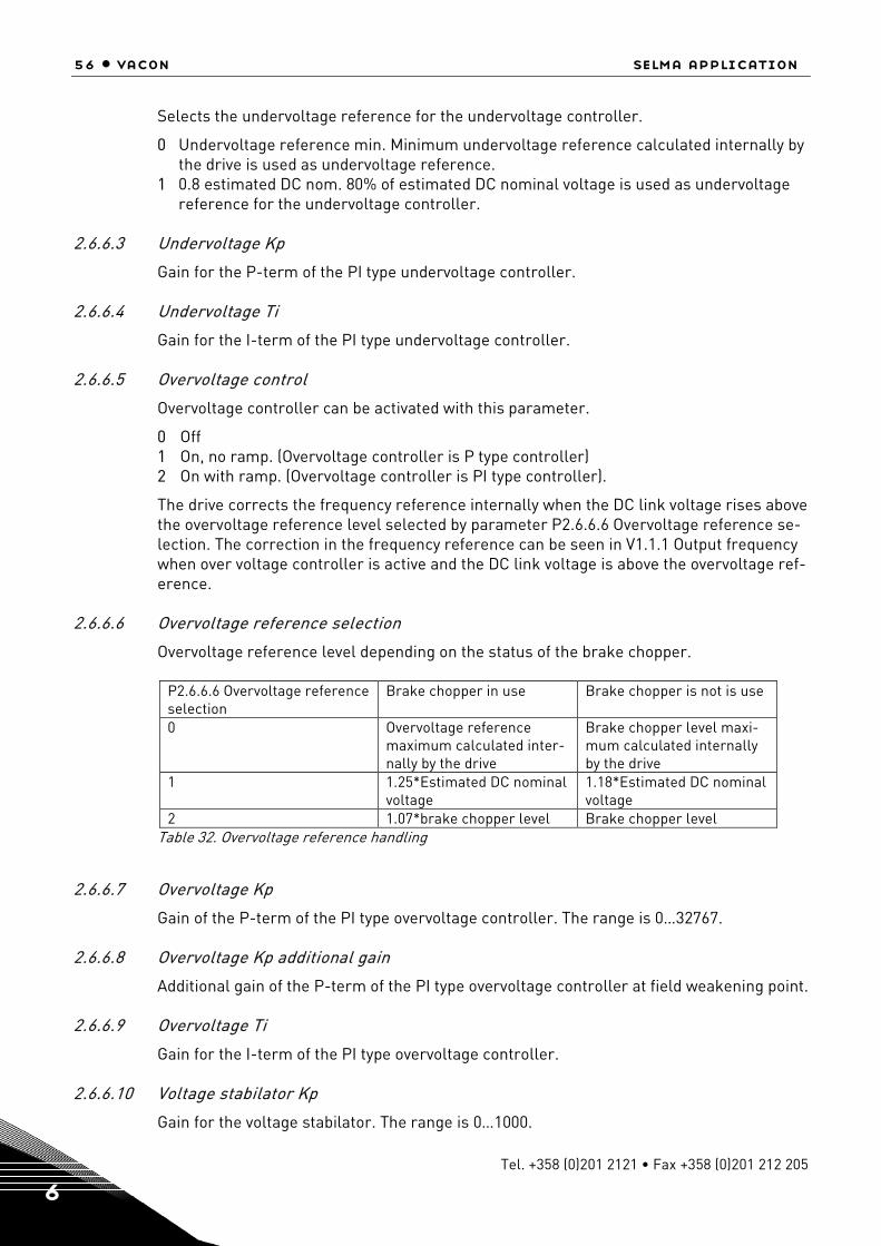
56 • vacon selma application
Tel. +358 (0)201 2121 • Fax +358 (0)201 212 205 6
Selects the undervoltage reference for the undervoltage controller.
0 Undervoltage reference min. Minimum undervoltage reference calculated internally by the drive is used as undervoltage reference.
1 0.8 estimated DC nom. 80% of estimated DC nominal voltage is used as undervoltage reference for the undervoltage controller.
2.6.6.3 Undervoltage Kp
Gain for the P-term of the PI type undervoltage controller.
2.6.6.4 Undervoltage Ti
Gain for the I-term of the PI type undervoltage controller.
2.6.6.5 Overvoltage control
Overvoltage controller can be activated with this parameter.
0 Off 1 On, no ramp. (Overvoltage controller is P type controller) 2 On with ramp. (Overvoltage controller is PI type controller).
The drive corrects the frequency reference internally when the DC link voltage rises above the overvoltage reference level selected by parameter P2.6.6.6 Overvoltage reference se-lection. The correction in the frequency reference can be seen in V1.1.1 Output frequency when over voltage controller is active and the DC link voltage is above the overvoltage ref-erence.
2.6.6.6 Overvoltage reference selection
Overvoltage reference level depending on the status of the brake chopper.
P2.6.6.6 Overvoltage reference selection
Brake chopper in use Brake chopper is not is use
0 Overvoltage reference maximum calculated inter-nally by the drive
Brake chopper level maxi-mum calculated internally by the drive
1 1.25*Estimated DC nominal voltage
1.18*Estimated DC nominal voltage
2 1.07*brake chopper level Brake chopper level Table 32. Overvoltage reference handling
2.6.6.7 Overvoltage Kp
Gain of the P-term of the PI type overvoltage controller. The range is 0…32767.
2.6.6.8 Overvoltage Kp additional gain
Additional gain of the P-term of the PI type overvoltage controller at field weakening point.
2.6.6.9 Overvoltage Ti
Gain for the I-term of the PI type overvoltage controller.
2.6.6.10 Voltage stabilator Kp
Gain for the voltage stabilator. The range is 0…1000.
selma application vacon • 57
24-hour support +358 (0)40 837 1150 • Email: [email protected] 6
The function of the voltage stabilator is to stabilise the variations in the DC link voltage caused due to load or incoming supply variations.
2.6.6.11 Voltage stabilator TC
Damping rate for the voltage stabilator. The range is 0…1000. 6.5.7 Motor control
2.7.1 Start function
Selects the mode of starting of the motor.
0 Normal ramp. The drive is started from zero reference with the acceleration ramp times.
1 Flying start. The drive finds the motor speed either from encoder speed in closed loop or by performing a fast test and internal calculation in open loop motor control opera-tion.
During normal running P2.5.1 Acceleration time 1 is used and in constant speed /inching operation P2.5.6 Constant speed acceleration time is used. Please note that in closed loop motor control operation the starting of the motor is always like a flying start independent of the parameter settings.
2.7.2 Stop function
Selects the mode of stopping the motor except in case of emergency stop.
0 Coast stop. The motor is allowed to stop on its own inertia. The drive control is stopped and the drive current is zero as soon as the runrequest is removed.
1 Ramp stop. The motor is stopped by the deceleration ramp time selected.
During normal running P2.5.2 Deceleration time 1 is used and in constant speed / inching operation P2.5.7 Constant speed deceleration time is used.
2.7.3 Emergency stop mode
Selects the mode of stopping the drive when emergency stop is active.
0 Coast stop. The motor is allowed to stop on its own inertia. 1 Ramp stop. The motor is stopped by the deceleration ramp time selected by P2.5.4
Emergency stop ramp. 2 Torque limit stop. The speed ramp generator output is forced to zero and the drive is
allowed to stop against its torque limits. 3 Constant power stop. The deceleration ramp time is internally updated so that the drive
stops at constant power if the parameters P2.8.13 System inertia in Kg.m^2, P2.8.14 Max brake power in kW and P2.8.14 Max braking torque in Nm is set correctly for the system. This stop mode is used to be able to stop the drive as fast as possible in case of emergency stop when braking is done using limited braking power. It can also be used for coordinated emergency stop for common DC bus drives.
2.7.4 Motor control mode
Selects the motor control mode.
0 OL frequency. This is normal U/f control mode without encoder.

58 • vacon selma application
Tel. +358 (0)201 2121 • Fax +358 (0)201 212 205 6
1 OL speed. This is normal U/f control mode without encoder with slip compensation based on the calculated torque of the motor V1.1.5 Torque.
2 OL torque. This is current vector control with U and f references without encoder. 3 CL speed/torque. This is rotor flux vector control mode and it needs digital encoder
connected to the motor shaft.
2.7.5 Torque selection
Selects the different configurations possible for speed and torque control when P2.7.4 Motor control mode = 3.
0 None. This can be used for closed loop speed control.
1 Speed. Closed loop speed control. The inertia/friction compensation can be given to P2.4.19 Torque step. The P2.4.8 Torque reference source selection is internally set to zero (None) to avoid any external torque reference.
2 Torque. This is the closed loop torque control. P2.4.8 Torque reference source selec-tion selects the torque reference source. The torque reference can be V1.2.16 Master torque reference from the master drive in case of master follower application, V1.2.17 Fieldbus torque reference from fieldbus or V1.2.18 I/O torque reference from analogue input.
3 Min. In this mode minimum of speed controller output V1.2.11 SPC OUT and external torque reference is selected as final torque reference V1.2.22 Used torque reference. This is typically used in winder control applications. External torque reference is cal-culated from the required tension and system parameters like roll diameter, gearbox ratio, web width and motor data. The overspend reference is added to the normal web speed reference.
4 Max. In this mode maximum of speed controller output V1.2.11 SPC OUT and external torque reference is selected as final torque reference V1.2.22 Used torque reference. This is typically used in unwinder control applications. External torque reference is calculated from the required tension and system parameters like roll diameter, gear-box ratio, web width and motor data. The under speed reference is added to the normal web speed reference.
5 Window. The drive is allowed to run in torque control as long as the speed is within the speed window around the speed reference. The speed window is denied by parameters P2.9.13 Window positive RPM and P2.9.14 Window negative RPM. When the speed is out of window the drive is switch to speed control to correct the error between V1.2.9 Used speed reference and V1.2.1 Speed measured. The drive remains in the speed control till the speed measured falls in a window around the speed reference. The hysteresis for the window is defined by P2.9.15 Window off positive and P2.9.16 Window off nega-tive.
2.7.6 Current control Kp
Gain for the current controller in closed loop motor control operation. Range 1…10000. Please note that in normal cases the default value is sufficient and there is no need to change this parameter.
2.7.7 Current control Ti
Integral time constant for the current controller in closed loop motor control operations. Range 0….100.0 ms. Please note that in normal cases the default value is sufficient and there is no need to change this parameter.

selma application vacon • 59
24-hour support +358 (0)40 837 1150 • Email: [email protected] 6
2.7.8 Switching frequency
Switching frequency in KHz for the IGBTs for the motor control. Please note that the de-fault value is decided by the drive depending on the power size of the drive. For all the drives with 690V supply voltage the maximum switching frequency is 1.5KHz. The switching frequency can be reduced in case of long motor cables (100m for <1.5kW and 300m for >1.5kW) or very small motors.
2.7.9 Dynamic damp Kp
Dynamic damping gain when P2.7.5 Torque select is either Torque/Min/Max/Window. The value 1.00 means nominal torque for nominal speed difference. Dynamic damping is in-tended to reduce mechanical resonance by adding damping torque proportional to speed error.
2.7.10 Dynamic damp TC
Decaying time for damping torque in ms. 0= Static damping.
2.7.11 DC magnetisation current
This parameter can be set to quickly magnetise the motor during starting. DC current of the amount set by this parameter is injected into the motor windings.
2.7.12 DC magnetisation time
The DC magnetisation current set by P2.7.11 DC magnetisation current is injected in the motor for this time. The speed reference to the ramp generator is then released.
2.7.13 Start 0 speed time
The time delay to release the speed reference to the ramp generator after the run request is given to the drive.
2.7.14 Stop 0 speed time
Time for which the zero speed reference is applied to the drive after ramp stop. 2.7.15 Stop state flux
The amount of flux as a percentage of motor nominal flux maintained in the motor after the drive is stopped. The flux is maintained for the time set by P2.7.16 Flux off delay. This parameter can be used only in closed loop motor control operation.
2.7.16 Flux off delay
The flux defined by P2.7.15 Stop state flux is maintained in the motor for the set time after the drive is stopped.
0 No flux after the motor is topped. Normal stop. >0 The flux off delay in seconds. <0 The flux is maintained in the motor after stop till the next run request is given to the drive. After the run request the flux is equal to the P2.4.16 Flux reference.

60 • vacon selma application
Tel. +358 (0)201 2121 • Fax +358 (0)201 212 205 6
6.5.8 PMSM control
The parameters in this group can be adjusted only when permenant magnet motor is used. 2.7.17.1 Flux control Kp
Gain for the flux current controller in %. It can be adjusted if instability near or in the field weakening area is observed.
2.7.17.2 Flux control Ti
Integral time constant for flux current controller in ms.
2.7.17.3 Resistance identification
Stator resistance identification can be done during every start by enabling this parameter.
2.7.17.4 Modulation index
Modulation index in % for closed loop operation. Higher values of motor terminal voltage can be achieved by increasing this value.
2.7.17.5 Encoder angle offset
Low word of absolute encoder angle corresponding to shaft zero position is indicated in this parameter. This parameter is identified during ID Run =3 when absolute encoder is used with PMSM motor. This parameter is only for monitoring and back up purposes and should not be changed manually.

selma application vacon • 61
24-hour support +358 (0)40 837 1150 • Email: [email protected] 6
6.5.9 Limit settings
2.8.1 Zero speed level
Absolute speed below which the bit 11 of the auxiliary status word is set. 2.8.2 Zero speed monitoring
Zero speed can be monitored either from V1.2.7 Speed ramp out or from V1.1.2 Speed.
0 Speed ramp out 1 Speed Act. In case of open loop motor control operation it is calculated motor speed
and in case of closed loop motor control operation it is speed measured from the en-coder.
2.8.3 Speed maximum
Maximum speed limit for the drive. 2.8.4 Speed minimum
Minimum speed limit for the drive. 2.8.5 Current limit
The current limit to the drive. The default value of this parameter depends on the power size of the drive.
2.8.6 Motoring torque limit
Motoring side torque limit for the drive as a percentage of the motor nominal torque. 2.8.7 Generator torque limit
Generator side torque limit of the drive as a percentage of the motor nominal torque.
2.8.8 Speed controller out max
Maximum torque limit for the speed controller output as a percentage of the motor nomi-nal torque.
2.8.9 Speed controller out min
Minimum torque limit for the speed controller output as a percentage of the motor nomi-nal torque.
2.8.10 Motoring power limit
Power limit for the motor side operation as a percentage of nominal power of the motor.
2.8.11 Generator power limit
Power limit for the generator side operation as a percentage of nominal power of the mo-tor.
2.8.12 Pullout torque
Amount of maximum torque (breakaway torque) the motor can produce. It can be set as a percentage of motor nominal torque.

62 • vacon selma application
Tel. +358 (0)201 2121 • Fax +358 (0)201 212 205 6
2.8.13 System inertia
Inertia of the complete drive system in Kg.m^2 including inertia of motor, gearbox and fixed load. This parameter is set when P2.7.3 Emergency stop mode = 3 Constant power stop.
2.8.14 Max brake power
Maximum braking power limit in KW in case of emergency stop when P2.7.3 Emergency stop mode = 3 Constant power stop
2.8.15 Max braking torque
Maximum braking torque in case of emergency stop when P2.7.3 Emergency stop mode =3 Constant power stop.
6.5.10 Speed control
W SPC Kp N0
W SPC Kp FWP
Gain -%
Speed
No PointW
W N1 PointMotor Nom SpeedW
SPC KpW
Figure 2. Speed controller adaptive gain
The transfer function for the speed controller is as given below. SPC OUT(k) = SPC OUT(k-1) + SPc Kp*[Speed Error(k) – Speed Error(k-1)] + Ki*Speed error(k). Where Ki = SPC Kp*Ts/SPC Ti. 2.9.1 Speed controller Kp
Gain for the speed controller in closed loop motor control operation. Gain value 100 means nominal torque reference is produced at the speed controller output for the fre-quency error of 1Hz.
2.9.2 Speed controller Ti
Integral time constant in ms for the speed controller in closed loop motor control opera-tion.
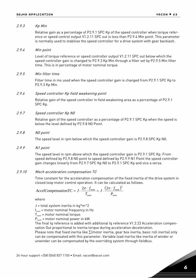
selma application vacon • 63
24-hour support +358 (0)40 837 1150 • Email: [email protected] 6
2.9.3 Kp Min
Relative gain as a percentage of P2.9.1 SPC Kp of the speed controller when torque refer-ence or speed control output V1.2.11 SPC out is less than P2.9.4 Min point. This parameter is normally used to stabilise the speed controller for a drive system with gear backlash.
2.9.4 Min point
Level of torque reference or speed controller output V1.2.11 SPC out below which the speed controller gain is changed to P2.9.3 Kp Min through a filter set by P2.9.5 Min filter time. This is in percentage of motor nominal torque.
2.9.5 Min filter time
Filter time in ms used when the speed controller gain is changed from P2.9.1 SPC Kp to P2.9.3 Kp Min.
2.9.6 Speed controller Kp field weakening point
Relative gain of the speed controller in field weakening area as a percentage of P2.9.1 SPC Kp.
2.9.7 Speed controller Kp N0
Relative gain of the speed controller as a percentage of P2.9.1 SPC Kp when the speed is below the level defined by P2.9.8 N0 Point.
2.9.8 N0 point
The speed level in rpm below which the speed controller gain is P2.9.8 SPC Kp N0.
2.9.9 N1 point
The speed level in rpm above which the speed controller gain is P2.9.1 SPC Kp. From speed defined by P2.9.8 N0 point to speed defined by P2.9.9 N1 Point the speed controller gain changes linearly from P2.9.7 SPC Kp N0 to P2.9.1 SPC Kp and vice a versa.
2.9.10 Mech acceleration compensation TC
Time constant for the acceleration compensation of the fixed inertia of the drive system in closed loop motor control operation. It can be calculated as follows.
( )nom
2nom
nom
nom 22P
fJ
Tf
JnsationTCAccelCompe⋅
⋅=⋅
⋅=ππ
where
J = total system inertia in kg*m^2 fnom = motor nominal frequency in Hz Tnom = motor nominal torque. Pnom = motor nominal power in kW. The final Iq reference is added with additional Iq reference V1.2.23 Acceleration compen-sation Out proportional to inertia torque during acceleration deceleration. Please note that fixed inertia like ∑(motor inertia, gear box inertia, basic roll inertia) only can be compensated with this parameter. Variable load inertia like inertia of winder or unwinder can be compensated by the overriding system through fieldbus.

64 • vacon selma application
Tel. +358 (0)201 2121 • Fax +358 (0)201 212 205 6
2.9.11 Acceleration compensation filter time
Filter time constant in ms for the mechanical inertia compensation.
2.9.12 Load drooping
Load drooping as a percentage of nominal speed at nominal torque. Load drooping allows the static speed error as a function of a load torque. For e.g. If Load drooping is set as 10% then for 100% motor torque the drive will allow actual speed less than 10% Nominal speed of themotor. It can be used to smoothen out the load torque variation or also to share the load torque between the two drive systems when the coupling between the drive systems is not rigid.
2.9.13 Drooping time
Load drooping time in ms. When the time is set to zero, the drooping is used as static or continuous drooping. Any non zero value activates the dynamic drooping and is active for the time specified.
2.9.14 Window positive RPM
This parameter is required to be set when P2.7.5 Torque select = 5. It defines the window area above the speed reference in rpm. The drive remains in torque control as long as speed is within the window area. For the speed out of the window area the drive is switched to speed control to correct the error between speed reference and speed meas-ured.
2.9.15 Window negative RPM
This parameter is required to be set when P2.7.5 Torque select = 5. It defines the window area below the speed reference in rpm. The drive remains in torque control as long as speed is within the window area. For the speed out of the window area the drive is switched to speed control to correct the error between speed reference and speed meas-ured.
2.9.16 Window off positive
This parameter is required to be set when P2.7.5 Torque select = 5. It defines the upper half hysteresis for the window defined by P2.9.13 Window positive RPM.
2.9.17 Window off negative
This parameter is required to be set when P2.7.5 Torque select = 5. It defines the lower half hysteresis for the window defined by P2.9.14 Window negative RPM.
2.9.18 Slip adjust
This parameter can be tuned to compensate for inaccuracies in the motor nominal speed data on the motor nameplate. Also the V1.2.36 Rotor time constant estimated by the mo-tor model can be adjusted with this parameter. The rotor time constant varies with the motor temperature. The compensation for the rotor time constant as a function of meas-ured motor temperature using either TS1or TS2 (PT100 temperature sensor) can be given by setting P2.13.29 Motor temperature compensation. The P2.9.17 Slip adjust is then in-ternally modified as a function of measured motor temperature.
selma application vacon • 65
24-hour support +358 (0)40 837 1150 • Email: [email protected] 6
2.9.19 Warm motor slip
Relative slip as a percentage of P2.9.17 Slip adjust for the warm motor. This is set when internal thermal model for motor temperature calculation is used. The calculated motor temperature is seen as V1.1.21 Motor temperature calculation as a percentage of motor nominal temperature.
2.9.20 Speed error filter time
Filter time in ms for the speed error between V1.2.9 Used speed reference and V1.2.1 Speed measured. The filtered error is then fed to the speed controller.
2.9.21 Actual speed filter time
Filter time in ms for speed measured from the encoder. The filtered speed is used to cal-culate V1.2.10 Speed error, which is fed to speed controller.
66 • vacon selma application
Tel. +358 (0)201 2121 • Fax +358 (0)201 212 205 6
6.5.11 Oscillation damp
2.10.1 Oscillation damp selection
Oscillation damping feature of the drive can be enabled using this parameter. This feature can be used to dampen the constant frequency torque oscillations in the drive system.
0 Not in use 1 Band pass. Oscillation damping with band pass filter. 2 BandStop+BandPass. Oscillation damping with band stop and band pass filter.
2.10.2 Oscillation frequency
Frequency of torque oscillations to be damped in Hz.
2.10.3 Oscillation damp gain
The gain for the oscillation damping. This changes the amplitude of compensating signal used for oscillation damping.
2.10.4 Phase shift
The compensating signal used for oscillation damping can be phase shifted 0 to 360 de-grees using this parameter.
6.5.12 Brake and fan control
2.11.1 Brake lift delay
Delay in receiving the feedback from the mechanical brake after giving a brake open re-quest from the digital/relay output. The speed reference is not released till the brake lift is acknowledged. If the brake lift acknowledgement does not come within the Brake lift delay time then the drive trips on F57 Mechanical brake.
2.11.2 Brake in emergency stop
Defines the action of the mechanical brakes controlled through drive in case of emer-gency stop.
0 At zero speed. The mechanical brake is closed at zero speed after the emergency stop is active.
1 Immediate. The brake is closed immediately after the emergency stop is active.
P2.11.3 Brake in fault
Defines the action of the mechanical brakes controlled through drive in case of fault in the drive.
0 At zero speed. The mechanical brake is closed at zero speed after the fault in the drive. 1 Immediate. The brake is closed immediately after the fault in the drive.
2.11.4 Motor fan off delay
The external fan can be controlled by setting digital/relay output parameters. The fan is started with the run request and stopped when the motor is stopped and the Motor fan off delay time is elapsed.

selma application vacon • 67
24-hour support +358 (0)40 837 1150 • Email: [email protected] 6
6.5.13 Master Follower
The master follower in VACON NXP drives is implemented by adding an OPT-D1/OPT-D2 board in slot D or slot E. The master and follower drives are then connected using optic fi-bre cable network. The OPT-D2 card with optic fibre link in NXP uses Vacon system bus for fast drive-to-drive communication.
2.12.1 M/F mode
When drive is required to be configured in master follower application this parameter can be set.
0 None. Drive runs as individual drive. 1 Master. Drive runs as a master. 2 Follower. Drive runs as follower and share either speed or torque from the follower
drive or both. When the drive is controlled from fieldbus P2.6.1 Control place = 0 then V1.2.37 Main control word from the fieldbus is used for controlling the drive. When P2.6.1 Control place is 1 = I/O or 2 = Local (Keypad) or 3 = PC Control, then follower drive is controlled by the internal control word from the master drive on the system bus. The follower drive then starts running with the master drive.
2.12.2 Follower speed reference
Sets the source of speed reference for the follower drive. This parameter is to be set only in the follower drive.
0 Follower. Speed reference is generated in the follower drive itself depending on active control place as per P2.6.1 Control place.
1 Master reference. Speed reference is taken form master drive V1.2.4 Speed ref. 1. 2 Master ramp. Speed reference is taken from master drive V1.2.9 Used speed refer-
ence. The ramp generator of the follower drive is then bypassed internally. The parameter settings for master and follower drives are to be done as per the table be-low.
2.12.3 Follower start delay
The delay time in starting multiple wind follower after the master is started. As the name suggests, the parameter is valid only if the drive is defined as follower.
Parameter Master Follower Remarks P2.12.1 M/F Mode 1 Master 2 Follower Sets the master follower
mode P2.7.4 Motor Control mode = 0 OL Freq
= 1 OL Speed = 3 CL Speed/Torq
If set = 0/1 then only speed follower is possible.
P2.7.5 Torque Select 0= None 1= Speed 2 = Torque 3 = Min 4 = Max 5 = Window
To be set as per the applica-tion requirement.

68 • vacon selma application
Tel. +358 (0)201 2121 • Fax +358 (0)201 212 205 6
P2.4.8 TRef Source Sel 0 = None External torque reference is
not used. 1 = Master Torque reference from the
master drive. 2 = Fieldbus Torque reference from the
fieldbus. 3 = Analogue I/P Torque reference from the
analogue I/P 1 or 2. P2.12.4 Follower SpRef This parameter is to be set
only in follower drive. 0 = Follower Speed reference is generated
in the follower drive itself de-pending on active control place as per P2.6.1 Control Place.
1 = Master Ref Speed reference is taken form master drive V1.2.4 Speed Reference 1.
2= Master Ramp Speed reference is taken from master drive V1.2.9 Used Speed Ref. The ramp genera-tor of the follower drive is then bypassed internally.
If System software <NXP00002V134
If system software >= NXP00002V134
For system software less than NXP00002V134 the speed is al-ways selected as 12Mbps. For system software greater than equal to NXP00002V134 0 = 1 = 2 = 3 = 4 = 5 = 6 =
System software less than NXP00002V134 do not show the parameters for NXOPTD2 card in M7 Expander Boards menu.
P2.12.2 SB Node ID P7.4.1.2.3 System bus Id Node ID no. for the master drive. Possible values are 1...63.
P2.12.3 SB Next Node ID P7.4.1.2.4 System bus NextId
Node ID for the next drive in the master follower commu-nication. Possible values are 1...63.
P7.4.1.2.1 System bus in use =1
For system software less than NXP00002V134 this signal is internally set to 1 if P2.12.2 and P2.12.3 are non-zero.
P7.4.1.2.2 System Bus speed
Table 33. Master Follower parameters

selma application vacon • 69
24-hour support +358 (0)40 837 1150 • Email: [email protected] 6
6.5.14 Protections
2.13.1 AI<4mA
Action in case of Analogue input fault. If the voltage or current at the analogue input ter-minal is less than a minimum value specified by P2.3.9 AI1 Minimum and P2.3 13 AI2 Minimum then analogue input fault is triggered.
0 No action. 1 Warning. Drive operation continues with F50 Anlg Lin<4mA. V1.2.44 Alarm word 1.Bit9
is set. 2 Fault. Drive trips on fault F50 Anlg Lin<4mA and V1.2.42 Fault Word 1 .Bit15 is set.
2.13.2 Panel communication
Action in case of loss off communication between drive control unit and keypad.
1 Warning. Drive operation continues with F52 Keypad communication warning and V1.2.44 Alarm word 1 .Bit15 is set.
2 Fault. The drive trips if P2.6.1 Control Place = 2 (Local) i.e. if the drive is running from keypad and V1.2.42 Fault Word 1.Bit11 is set.
2.13.3 External fault
Action when external fault is activated by digital input.
1 Warning. Drive operation continues with F51 External fault warning. 2 Fault. The drive trips on F51 External fault with fault word 2. Bit6 is set.
2.13.4 Input phase supervision
Action in case of loss of one or more input phase supply to the frequency converter. The parameter is to be set to zero for inverter.
0 No action. Drive operation continues with no warning or fault indication. 1 Fault. Drive trips with F10 Input phase fault and V1.2.42 Fault word 1. Bit8 is set.
2.13.5 Output phase supervision
Action in case of loss of one or more output phases connected between drive output and motor.
0 No action. 1 Warning. Drive operation continues with warning F11 Output phase and V1.2.44 Alarm
word 1. Bit4 is set. 2 Fault. Drive trips on F11 Output phase and V1.2.43 Fault word 2. Bit0 is set.
Please note that this protection cannot find the loss of motor connection in case of mul-timotor connection to one drive output.
2.13.6 Earth fault
Action in case of Earth fault in the motor or motor cables.
0 No action 1 Fault. Drive trips on F3 Earth fault and V1.2.42.Bit4 is set.

70 • vacon selma application
Tel. +358 (0)201 2121 • Fax +358 (0)201 212 205 6
2.13.7 Earth fault current
If the sum of the motor phase currents is higher than the level set by this parameter then earth fault is triggered and the action is taken as per the setting of P2.13.5 Earth fault and P2.13.7 Earth fault delay. The typical value for earth fault current monitoring is 5% of drive nominal current V1.1.17 Unit nominal current.
2.13.8 Earth fault delay
Earth fault is triggered if the sum of motor phase currents remains higher than the level set by P2.13.6 Earth fault current for the time set by this parameter.
2.13.9 Motor stall
Action in case of motor stall condition. Motor is said to be in stall condition if the motor current is higher than the P2.13.9 Stall current and output frequency is less than P2.13.10 Stall frequency limit and motor remains in this condition for a time higher than P.13.11 Stall time limit in seconds.
0 No action. Drive continues operation with no warning or fault indication. 1 Warning. The drive continues operation with F15 Motor stall warning and V1.2.44 Alarm
word 1.Bit0 is set. 2 Fault. The drive trips on F15 Motor stall and V1.2.42. Bit3 is set.
2.13.10 Stall current
The current level in amperes for monitoring stall condition of the motor.
2.13.11 Stall frequency limit
The output frequency level below which monitoring of motor stall condition is active.
2.13.12 Stall time limit
If the motor remains in stall condition defined by P2.13.9 Stall current and P2.13.10 Stall frequency limit for a time higher than the time set by this parameter then motor stall fault is triggered.
2.13.13 Thermistor
If the drive is installed with OPT-A3 board in slot B then one thermistor can be connected to the drive through it for motor over temperature indication to the drive. This parameter sets the action by the drive in case of motor over temperature through thermistor.
0 No action 1 Warning. The drive continues its operation with warning F61 Thermistor and V1.2.44
Alarm word 1. Bit1 is set. 2 Fault. Drive trips on fault F61 Thermistor and V1.2.42 Fault word 1. Bit7 is set.

selma application vacon • 71
24-hour support +358 (0)40 837 1150 • Email: [email protected] 6
2.13.14 Encoder fault
The action in case of loss of encoder signal when drive is running in closed loop control. The drive generates fault or alarm F43 Encoder and V1.2.43 fault word 2. Bit2 is set if the encoder connected to OPT-A5 in slot C is faulty or wrongly connected.
0 No action 1 Warning 2 Fault
Following are the sub codes generated with the fault in different fault conditions.
Sub code 1. Channel A is missing Sub code 2. Channel B is missing Sub code 3. Both channel are missing Sub code 4. Encoder reversed Sub code 5. Card is missing
2.13.15 Mechanical brake fault
Mechanical brake fault monitoring is automatically enabled if P2.2.6 Mechanical brake acknowledgement is (non zero) set to 1….8. i.e. either if DIN1…4 or inverted DIN1…4 is se-lected to acknowledge the brake status. The brakes are lifted through the digital/relay output when run request is given and 70% of motor flux is generated (only in closed loop motor control operation). If the brake lift acknowledgement does not arrive at selected digital input with time specified by P2.11.1 Brake lift delay then the mechanical brake fault is triggered and drive takes action as per the setting of this parameter.
1 Warning. Drive continues operation with warning F57 Mech. brake and V1.2.44 Alarm word 1. Bit14 is set.
2 Fault. Drive trips on F57 Mechanical brake and V1.2.43 Fault word 2. Bit10 is set.
2.13.16 Follower timeout
This parameter is to be set in case of master follower application. The parameter is to be set only in follower drives. The master drive sends a watchdog (1 second ON/OFF square wave) to the follower drive. If the follower drive does not receive the watchdog signal for a time higher than that defined by this parameter then drive trips on fault F55 Follower communication and V1.2.42 Fault word 1. Bit13 is set. This indicates that the follower drive has lost the communication with master drive. Please note that this fault is detected only in follower drive.
2.13.17 Fieldbus watchdog delay
Delay time to indicate loss of data on fieldbus from overriding system. The overriding sys-tem sends the watchdog signal (square wave of 1 second time period) at V1.2.37 Main con-trol word. Bit11. If the drive does not receive this signal for a time higher than the time de-fined by this parameter then the drive trips on fault F53 Fieldbus communication and V1.2.42 Fault word 1. Bit12 is set. The fault occurs only if P2.6.1 Control place = 0 Fieldbus i.e. the drive is controlled from fieldbus. The same watchdog signal is sent back to the overriding system at V1.2.39 Main status word. Bit15. Setting this parameter to zero will disable this watchdog monitoring function. In addition to this the fieldbus option card monitors the communication with fieldbus master and is

72 • vacon selma application
Tel. +358 (0)201 2121 • Fax +358 (0)201 212 205 6
always active. In case of loss of communication with the master, the drive trips on F53 Fieldbus communication fault.
2.13.18 PT100 number in use
PT100 sensors can be connected to Vacon drive for temperature measurement using the OPT-B8 card. Totally three channels are available for connection. With this parameter, se-lect the number of inputs channels used to connect the PT100 sensors.
2.13.19 PT100 alarm limit
Two PT100 temperature sensors can be connected to the drive using two analogue inputs AI1 and AI2 and AO1 (10mA). These two sensors are referred as PT100 (1) and PT100 (2). Or PT100 sensors can be connected using OPT-B8 card. This parameter sets the temperature level in celsius above which the drive generates the warning F56 PT100 temperature. The drive continues its operation and V1.2.44 Alarm word 1. Bit1 is set. Note that the alarm limit is common for all PT100 sensors connected to the system.
2.13.20 PT100 fault limit
This parameter sets the temperature level in celcius above which the drive trips on fault F56 PT100 temperature and V1.2.42 Fault word 1. Bit7 is set.
2.13.21 Motor temperature compensation
Two PT100 temperature sensors can be connected using analogue inputs AI1 and AI2 and AO1 (10mA) and they are referred as PT100 (1) and PT100 (2). One of the sensors is used normally to measure the motor winding temperature. This measured temperature can be used to compensate the slip adjust P2.9.17 Slip adjust internally. This is needed to adjust the motor model for the variation in rotor time constant as a function of temperature to acquire better torque accuracy. This parameter selects the temperature sensor to be used for compensation.
0 Compensation to slip adjust is not used. 1 Motor temperature for the slip adjust compensation is read from PT100 (1) sensor. 2 Motor temperature for the slip adjust compensation is read from PT100 (2) sensor.
The function work as follows. For e.g. If P2.9.17 Slip adjust is set to 100% and P2.13.29 Motor temperature compensa-tion = 1 (Compensation from PT100(1)sensor).
Internal slip adjust = [(PT100 (1) Temp. in celsius * 40)/100+60] * P2.9.17 Slip adjust/100. For temperature varying from 25 to 100 degrees celsius the slip adjust will vary internally from 70 to 100 %.

selma application vacon • 73
24-hour support +358 (0)40 837 1150 • Email: [email protected] 6
2.13.22 Motor calculated temperature protection
Drive has internal temperature calculation for the motor based on motor data and setting of P2.13.17 Thermal time constant, P2.13.18 Zero speed cooling and P2.13.19 Motor duty cycle. The calculated motor temperature can be seen as V1.1.21 Motor temperature cal-culation as a percentage of motor nominal temperature. The overheating of the motor is monitored by this function. This parameter sets the action in case of motor overheating triggered by calculated motor temperature.
0 No action 1 Warning. The drive continues operation with warning F16 Motor overtemperature and
V1.2.44 Alarm word1. Bit1 is set. 2 Fault. Drive trips on F16 Motor overtemperature and V1.2.42 Fault word 1. Bit7 is set.
2.13.23 Thermal time constant
Thermal time constant of the motor in minutes for the internal motor temperature calcu-lation.
2.13.24 Zero speed cooling
Motor cooling ability at zero speed as a percentage of that at full speed or its nominal cooling ability. This parameter is used in internal motor temperature calculation.
2.13.25 Motor duty cycle
Motor duty cycle for internal motor temperature calculation.
2.13.26 Underload protection
Action in case of underload condition. The drive is in underload condition if the load is less than the minimum load defined by the underload curve by P2.13.13 Speed zero load, P2.13.14 Speed nominal load and P2.13.15 Underload speed nominal.
0 No action 1 Warning. Drive continues operation with F17 Motor underload warning and V1.2.44
Alarm word1. Bit2 is set. 2 Fault. Drive trips on F17 Motor underload fault and V1.2.42 Fault word 1. Bit5 is set.
2.13.27 Speed zero load
Load level for underload monitoring at zero speed as a percentage of motor nominal torque.
2.13.28 Speed nominal load
Load level for underload monitoring for speed up to nominal speed defined by P2.13.15 Underload speed nominal.
2.13.29 Underload speed nominal
Speed limit below which the underload function is activated.
74 • vacon selma application
Tel. +358 (0)201 2121 • Fax +358 (0)201 212 205 6
6.5.15 Flux reference handling
This parameter group is used in closed loop motor control operation to set the flux lin-earization curve of the motor. With parameter P2.1.11 ID Run =2 With motor run , the pa-rameters in this group are automatically set. These parameters can also be set when flux linearization curve for the motor is done manually as explained below. Note: There should not be any load connected to the drive including gearbox while doing this test. Set P2.7.5 Torque selection = 1 i.e. Speed control. Set P2.4.16 Flux reference =100.0%. Monitor the signals V1.1.4 Current , V1.1.7 Motor voltage and V1.1.1 Output frequency. Run the motor with 50% of the nominal motor speed. Note the value of the V1.1.7 Motor voltage (V100). While keeping the speed reference constant change P2.4.16 Flux reference to 90.0% and note the value of V1.1.7 Motor voltage (V90). Set P2.14.9 Flux curve 9 = (V90/V100)*100. Reduce the P2.4.16 Flux reference in steps of 10% as 80%, 70%,.....,30 and note the value of V1.1.7 Motor voltage as V80,V70, …,V30 respectively. Set the values of P2.14.8 Flux curve 8, P2.14.7 Flux curve 7,…, P2.14.3 Flux curve 3 calculating the same way as in step f. Repeat this step by changing P2.4.16 Flux reference to 110%,120%,130% and note down V1.1.7 Motor voltage V110,V120,and V130 respectively. Set P2.14.11 Flux curve 11 , P2.14.12 Flux curve 12 , P2.14.13 Flux curve 13 calculating the same way as in step f. Interpolate values for 140% - 150% to set parameters P2.14.14, P2.14.15.
2.14.1- 1.14.15 Flux curve 10%, …….., Flux curve 150%
Motor voltage corresponding to 10%….150%c of flux as a percentage of Nominal flux volt-age.
selma application vacon • 75
24-hour support +358 (0)40 837 1150 • Email: [email protected] 6
6.5.16 Startup torque
The parameters in this group can be used in closed loop motor control operation. It en-ables the drive to produce programmable startup torque as soon as run request is given to the drive.
2.15.1 Startup torque selection
Select the source for producing the startup torque.
0 None. Programmable startup torque is not used. 1 Torque Memory. The drive memorises V1.1.5 Torque at the time previous stop and the
same torque is produced with the run request is given. 2 Torque reference. The torque reference for the startup torque is derived from external
torque reference selected by P2.4.8 Torque reference source selection. 3 FWD/REV. The torque reference for the startup torque is derived from P2.15.3 Startup
torque FWD in forward or positive direction of speed reference and P2.15.4 Startup torque REV in reverse or negative direction of speed reference.
2.15.2 Startup torque time
The startup torque is maintained after the run request for the time defined by this pa-rameter in 0…..10000 ms.
2.15.3 Startup torque FWD
Amount of startup torque to be produced with the run request as a percentage of motor nominal torque when the drive is run in forward or positive direction of speed reference. This parameter is applicable only if P2.15.1 Startup torque selection = 3 FWD/REV.
2.15.4 Startup torq REV
Amount of startup torque to be produced with the run request as a percentage of motor nominal torque when the drive is run in reverse or negative direction of speed reference. This parameter is applicable only if P2.15.1 Startup torque selection = 3 FWD/REV.
2.15.5 Torque memory source
When P2.15.1 Startup torque selection = 1 (Torque memory), then this parameter selects the source for memorising the torque to be produced at next run request.
0 Actual torque. V1.1.5 Torque is used as memory source for startup torque reference at next start.
1 Torque reference. This is reserved for future development and is not used in the pre-sent application.
2 External torque reference. The value defined by parameter P2.15.6 Torque memory reference is used as memory source for startup torque reference at next start.
2.15.6 Torque memory reference
When P2.15.5 Torque memory source = 2 then this parameter defines the amount of torque as a percentage of motor nominal torque used as memory source for startup torque reference at next start.

76 • vacon selma application
Tel. +358 (0)201 2121 • Fax +358 (0)201 212 205 6
6.5.17 Monitor settings
The parameters in this group are used for testing of the drives. These parameters are for factory use only and are not required to be changed on site.
2.16.1 Speed monitoring filter
Filter in ms for signal V1.1.2 Speed.
2.16.2 Current monitoring filter
Filter in ms for signal V1.1.4 Current.
2.16.3 Torque monitoring filter
Filter in ms for signal V1.2.5 Torque. 6.5.18 Data mapping
The parameters in this group are use when the drive has a communication with overriding system. The parameters or signals with ID nos. defined in this application can be con-nected to the signals to and from the overriding system for reading and writing purpose respectively.
2.17.1- 2.17.8 PD IN1 ID, ….., PD IN8 ID
ID no. of any signal or parameter defined in the application. The parameter or signal of this ID number is then connected to process data IN 1….IN10, written from overriding sys-tem to the drive.
2.17.9-2.17.16 PD OUT1 ID, ….., PD OUT8 ID
ID no. of any signal or parameter defined in the application. The parameter or signal of this ID number is then connected to process data OUT1….OUT10, read by the overriding system from the drive.
2.17.17 FB Mode
Defines, which mode is used in fieldbus control 1 ProfiDrive mode. Sets also ProfiBus board mode to ProfiDrive. Powers off the drive after
change 2 Bypass mode. Sets also ProfiBus board mode to ProfiDrive. Powers off the drive after
change. 3 Not used 4 Selma mode 5 MicroStar mode

selma application vacon • 77
24-hour support +358 (0)40 837 1150 • Email: [email protected] 6
6.6 Fieldbus profile
Note: Please note that the process data can be freely configured to any parameter or signal defined in the application using ID nos. The process data configuration shown below is just for example. 6.6.1 Process data signals from overriding system to Vacon drive.
Profibus data name Signal name Min Max Def FB
scale Scaling description
Main Control Word Main Control
Word See bitwise description below
Speed Reference Speed Refer-
ence -32000 32000 0 20000 corresponds to speed defined By param. Process speed
Process Data IN1 Torque Ref-
erence -3000 3000 0 10=1% 100% equals Motor Nominal Torque
Process Data IN2 Aux. Control
Word 1 See bitwise description below
Process Data IN3 Aux. Control
Word 2 See bitwise description below
Process Data IN4 Load Share
-4000 4000 1000 10=1% This scales the % of Torque Reference to Follower
Process Data IN5 Torque Step -3000 3000 0 10=1% 100% equals Motor Nominal Torque
Process Data IN6 Torque Select 0 5 0 0=none,1=speed,2=torque, 3=min,4=max,5=win
Process Data IN7 Positioning will be added In future releases
Process Data IN8 Master Fol-lower Mode 0 2 0
0=none,1=master,2=slave
Table 34.
6.6.2 Process data signals from Vacon drive to overriding system.
Profibus data name Signal name Min Max FB
scale Scaling description Main Status Word Main Status Word See bitwise description below
Motor Speed Motor Speed 20000 correspond to speed de-fined by P2.1.7 Process Speed
ProcessDat Out1 Motor
Torque 10=1% 100% equals Motor Nominal
Torque
ProcessDataOut2
Aux. Status Word See bit words below
ProcessDataOut3 Fault
Word1 See bit words below
ProcessDataOut4 Fault
Word2 See bit words below
ProcessDataOut5 Digital
Input Status Word See bit words below ProcessDataOut6 Alarm Word See bit words below
ProcessDataOut7 Motor Shaft Rounds -32768 32767 No of Rounds of the motor Shaft
after Pos reset is done
ProcessDataOut8 Motor Shaft Position 0 360 Position of the motor shaft in
degrees
Table 35.

78 • vacon selma application
Tel. +358 (0)201 2121 • Fax +358 (0)201 212 205 6
6.6.3 Main control word, par. 2.17.17 (FB Mode) = 1-3
Bit 0 On 0>1 will reset the Switch On Inhibit state and bring the drive to Rdy Run. Should be reset after fault and EmStop .
Bit 1 Coast Stop 0=Coast stop Active 1=Coast Stop not Active
Bit 2 Emergency Stop
0=Emergency stop active 1=Emergency stop not active EmStop Mode is selected by P2.7.3
Bit 3 Run 0= stops the drive as per Stop Mode P2.7.2 1= Run
Bit 4 Ramp Out Zero 0=Ramp Output forced to 0. 1=Ramp Output is released
Bit 5 Ramp Hold 0=Ramp is hold 1=ramp release
Bit 6 Ramp input Zero 0=Ramp input forced to 0.Stop by Ramp 1=Ramp input is released
Bit 7 Reset 0>1 Reset fault.
Bit 8 Inching 1 0=No Action 1=Run forward with Constant Speed set by P2.4.2
Bit 9 Inching 2 0=No Action 1=Run backward with Constant Speed set by P2.4.3
Bit 10 Fieldbus Control Enable 0=No control from Fieldbus possible 1=Drive control from profibus if P2.6.1 =0 Fieldbus
Bit 11 Watchdog
0>1>0>1…1 sec square wave clock. This is used to check data communica-tion between profibus master and the drive. Used to generate FB Commu-nication. Fault. This monitoring can be switched off by setting P2.14.26 PB Watchdog Delay =0.Drive´s internal communication monitoring is still ac-tive at this time.
Bit 12 Low not used Bit 13 Low not used Bit 14 Low not used Bit 15 Low not used
Table 36.
6.6.4 Selma Control Word, par. 2.17.17 (FB Mode) = 4
Bit 0 Ramp stop 0 = Stop by Ramp Not active 1 = Stop by Ramp active
Bit 1 Emergency stop
0 = Emergency stop Not active 1 = Emergency stop active Note! EmStop Mode is selected by P2.7.3
Bit 2 Run Enable 0 = Run Enable Not active 1 = Run Enable active and Drive stop by Coast
Bit 3 Reserved Not used Bit 4 Reserved Not used Bit 5 Reserved Not used Bit 6 Run 0 = Stops the drive as per Stop mode P2.7.2 1 = Run
Bit 7 Inching 1 0=No Action 1=Run forward with Constant Speed set by P2.4.2
Bit 8 Inching 2 0=No Action 1=Run backward with Constant Speed set by P2.4.3
Bit 9 Reserved Not used Bit 10 Reserved Not used Bit 11 Reserved Not used Bit 12 Reserved Not used Bit 13 Reserved Not used Bit 14 Reserved Not used Bit 15 Reserved Not used
Table 37
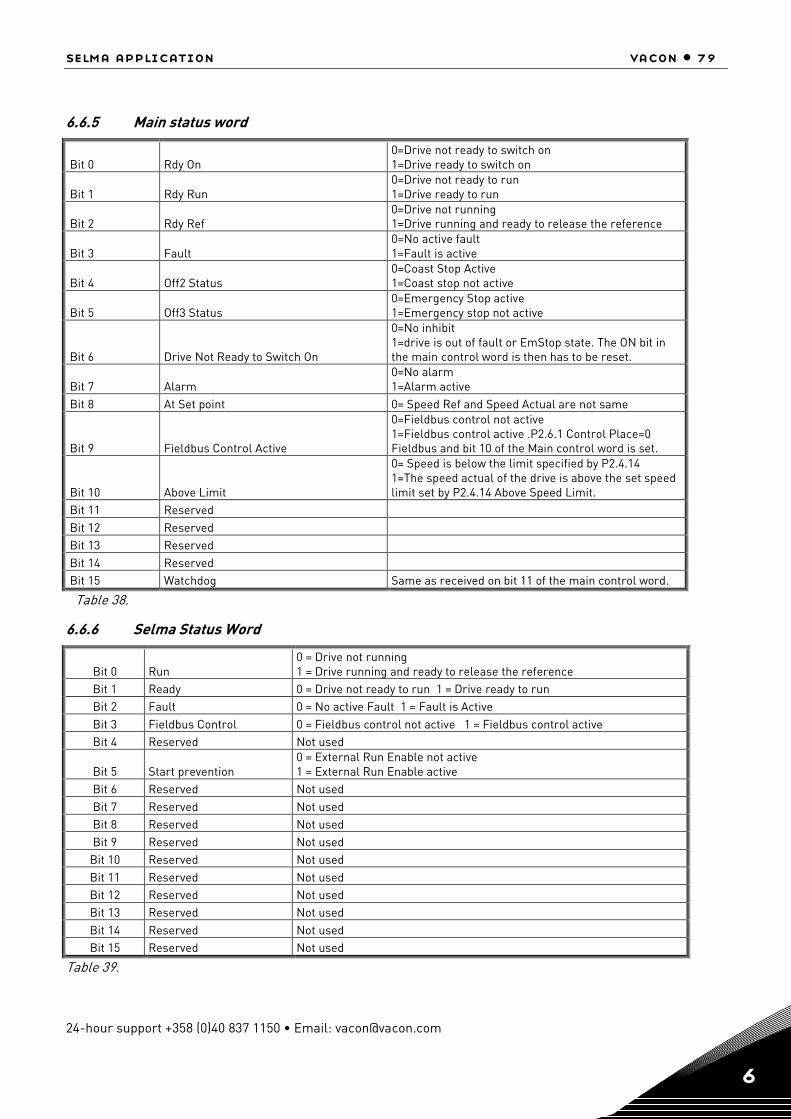
selma application vacon • 79
24-hour support +358 (0)40 837 1150 • Email: [email protected] 6
6.6.5 Main status word
Bit 0 Rdy On 0=Drive not ready to switch on 1=Drive ready to switch on
Bit 1 Rdy Run 0=Drive not ready to run 1=Drive ready to run
Bit 2 Rdy Ref 0=Drive not running 1=Drive running and ready to release the reference
Bit 3 Fault 0=No active fault 1=Fault is active
Bit 4 Off2 Status 0=Coast Stop Active 1=Coast stop not active
Bit 5 Off3 Status 0=Emergency Stop active 1=Emergency stop not active
Bit 6 Drive Not Ready to Switch On
0=No inhibit 1=drive is out of fault or EmStop state. The ON bit in the main control word is then has to be reset.
Bit 7 Alarm 0=No alarm 1=Alarm active
Bit 8 At Set point 0= Speed Ref and Speed Actual are not same
Bit 9 Fieldbus Control Active
0=Fieldbus control not active 1=Fieldbus control active .P2.6.1 Control Place=0 Fieldbus and bit 10 of the Main control word is set.
Bit 10 Above Limit
0= Speed is below the limit specified by P2.4.14 1=The speed actual of the drive is above the set speed limit set by P2.4.14 Above Speed Limit.
Bit 11 Reserved Bit 12 Reserved Bit 13 Reserved Bit 14 Reserved Bit 15 Watchdog Same as received on bit 11 of the main control word.
Table 38.
6.6.6 Selma Status Word
Bit 0 Run 0 = Drive not running 1 = Drive running and ready to release the reference
Bit 1 Ready 0 = Drive not ready to run 1 = Drive ready to run Bit 2 Fault 0 = No active Fault 1 = Fault is Active Bit 3 Fieldbus Control 0 = Fieldbus control not active 1 = Fieldbus control active Bit 4 Reserved Not used
Bit 5 Start prevention 0 = External Run Enable not active 1 = External Run Enable active
Bit 6 Reserved Not used Bit 7 Reserved Not used Bit 8 Reserved Not used Bit 9 Reserved Not used
Bit 10 Reserved Not used Bit 11 Reserved Not used Bit 12 Reserved Not used Bit 13 Reserved Not used Bit 14 Reserved Not used Bit 15 Reserved Not used
Table 39.
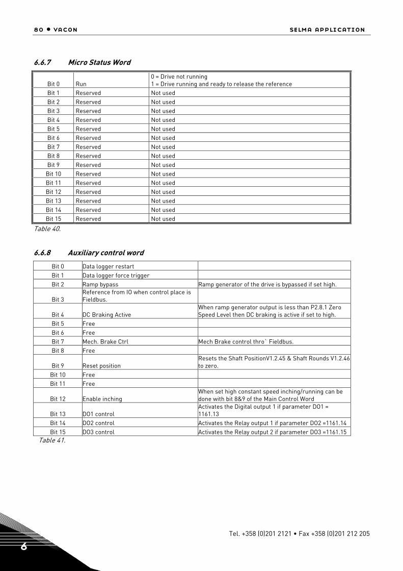
80 • vacon selma application
Tel. +358 (0)201 2121 • Fax +358 (0)201 212 205 6
6.6.7 Micro Status Word
Bit 0 Run 0 = Drive not running 1 = Drive running and ready to release the reference
Bit 1 Reserved Not used Bit 2 Reserved Not used Bit 3 Reserved Not used Bit 4 Reserved Not used Bit 5 Reserved Not used Bit 6 Reserved Not used Bit 7 Reserved Not used Bit 8 Reserved Not used Bit 9 Reserved Not used
Bit 10 Reserved Not used Bit 11 Reserved Not used Bit 12 Reserved Not used Bit 13 Reserved Not used Bit 14 Reserved Not used Bit 15 Reserved Not used
Table 40.
6.6.8 Auxiliary control word
Bit 0 Data logger restart Bit 1 Data logger force trigger Bit 2 Ramp bypass Ramp generator of the drive is bypassed if set high.
Bit 3 Reference from IO when control place is Fieldbus.
Bit 4 DC Braking Active When ramp generator output is less than P2.8.1 Zero Speed Level then DC braking is active if set to high.
Bit 5 Free Bit 6 Free Bit 7 Mech. Brake Ctrl Mech Brake control thro` Fieldbus. Bit 8 Free
Bit 9 Reset position Resets the Shaft PositionV1.2.45 & Shaft Rounds V1.2.46 to zero.
Bit 10 Free Bit 11 Free
Bit 12 Enable inching When set high constant speed inching/running can be done with bit 8&9 of the Main Control Word
Bit 13 DO1 control Activates the Digital output 1 if parameter DO1 = 1161.13
Bit 14 DO2 control Activates the Relay output 1 if parameter DO2 =1161.14 Bit 15 DO3 control Activates the Relay output 2 if parameter DO3 =1161.15
Table 41.

selma application vacon • 81
24-hour support +358 (0)40 837 1150 • Email: [email protected] 6
6.6.9 Auxiliary status word
Bit 0 Datalogger triggered
Bit 1 Window Control active and Speed is out of Window
Bit 2 Motor/Generator torque/current limit ac-tive
Bit 3 Undervoltage/Overvoltage controller ac-tive
Bit 4 Reverse direction Bit 5 IO Control Active Bit 6 Motor Fan ON command Bit 7 Mechanical brake lift command Bit 8 DC Charging OK (Pulse) Bit 9 DC Charging OK (continuous)
Bit 10 Drive in Torque control Bit 11 Speed Zero Bit 12 Reserved Bit 13 Reserved Bit 14 Reserved Bit 15 Reserved
Table 42.
6.6.10 Fault word 1
Bit 0 OverCurrent Bit 1 Overvoltage Bit 2 Undervoltage Bit 3 Motor Stall See parameter P2.14.8, P2.14.9, P2.14.10, P2.14.11 Bit 4 Earth Fault See parameter P2.14.5, P2.14.6, P2.14.7 Bit 5 UnderLoad See parameter P2.14.12, P2.14.13, P2.14.14, P2.14.15 Bit 6 Unit Over Temperature
Bit 7 Motor Temperature
This can be because of the following reasons. Thermistor as set by P2.14.24 PT100 Temp. measurement using PT100 type sen-sor.See parameters P2.2.2.3 to P2.2.2.6, P2.13.18 to P2.13.20 Calculated Overtemp as set by P2.13.22 to P2.13.24.
Bit 8 Input Phase Loss See parameter P2.14.3 Input Ph. Supervision Bit 9 Internal Brake Resistor Protection
Bit 10 Device Fault Device (slot cards)Removed,Added,changed,Unknown Bit 11 Keypad Communication Fault See parameter P2.14.2 Bit 12 Fieldbus communication Fault
Bit 13 Follower communication Master follower communication. See parameters P2.13.1, P2.13.2, P2.13.3.
Bit 14 Slot communication. slot comm. fault. One of the slot cards is faulty. Bit 15 Analogue Input Fault See parameter P2.14.1
Table 43.
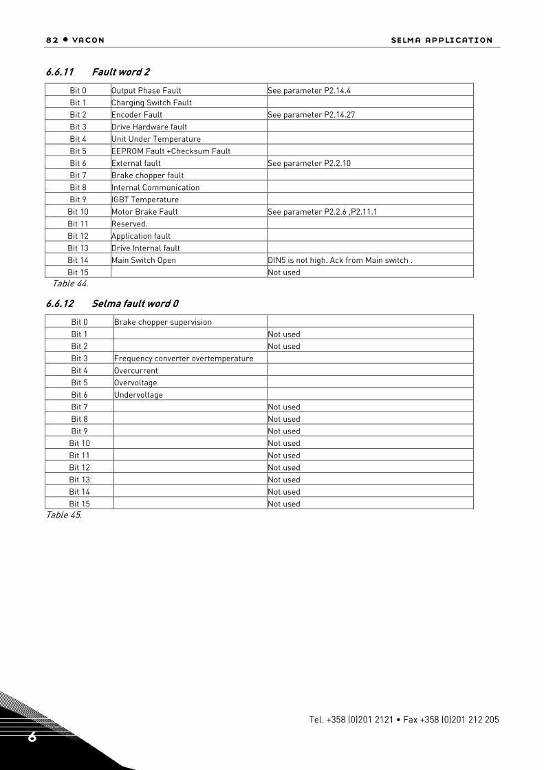
82 • vacon selma application
Tel. +358 (0)201 2121 • Fax +358 (0)201 212 205 6
6.6.11 Fault word 2
Bit 0 Output Phase Fault See parameter P2.14.4 Bit 1 Charging Switch Fault Bit 2 Encoder Fault See parameter P2.14.27 Bit 3 Drive Hardware fault Bit 4 Unit Under Temperature Bit 5 EEPROM Fault +Checksum Fault Bit 6 External fault See parameter P2.2.10 Bit 7 Brake chopper fault Bit 8 Internal Communication Bit 9 IGBT Temperature
Bit 10 Motor Brake Fault See parameter P2.2.6 ,P2.11.1 Bit 11 Reserved. Bit 12 Application fault Bit 13 Drive Internal fault Bit 14 Main Switch Open DIN5 is not high. Ack from Main switch . Bit 15 Not used
Table 44.
6.6.12 Selma fault word 0
Bit 0 Brake chopper supervision Bit 1 Not used Bit 2 Not used Bit 3 Frequency converter overtemperature Bit 4 Overcurrent Bit 5 Overvoltage Bit 6 Undervoltage Bit 7 Not used Bit 8 Not used Bit 9 Not used
Bit 10 Not used Bit 11 Not used Bit 12 Not used Bit 13 Not used Bit 14 Not used Bit 15 Not used
Table 45.

selma application vacon • 83
24-hour support +358 (0)40 837 1150 • Email: [email protected] 6
6.6.13 Selma fault word 1
Bit 0 Not used Bit 1 Not used Bit 2 Not used Bit 3 Not used Bit 4 Earth fault
Bit 5 Motor Over temperature, PT100 Thermis-tor
Bit 6 Not used Bit 7 Not used Bit 8 External fault Bit 9 IGBT fault
Bit 10 Not used Bit 11 System fault Bit 12 Fieldbus communication fault Bit 13 Panel communication fault Bit 14 Motor stall fault Bit 15 Encoder fault
Table 46.
6.6.14 Selma fault word 2
Bit 0 Not used Bit 1 Not used Bit 2 Not used Bit 3 Not used Bit 4 Not used Bit 5 Undervoltage controller active Bit 6 Not used Bit 7 Switch On Inhibit
Bit 8 Motor Over temperature, PT100 Thermis-tor
Bit 9 Not used Bit 10 Not used Bit 11 Not used Bit 12 Not used Bit 13 Not used Bit 14 Not used Bit 15 Not used
Table 47.

84 • vacon selma application
Tel. +358 (0)201 2121 • Fax +358 (0)201 212 205 6
6.6.15 Alarm word 1
Bit 0 Motor stalled See parameter P2.14.8, P2.14.9, P2.14.10, P2.14.11
Bit 1 Motor over temperature
This can be because of the following reasons. Thermistor as set by P2.13.13 measurement using PT100 type sensor.See parameters P2.2.2.3 to P2.2.2.6, P2.13.18 to P2.13.20 Calculated Overtemp as set by P2.13.22 to P2.13.24.
Bit 2 Motor under load See parameter P2.14.12, P2.14.13, P2.14.14, P2.14.15
Bit 3 Input phase loss See parameter P2.14.3 Input Phase Supervision Bit 4 output phase loss See parameter P2.14.4
Bit 5 Start Prevention
F26 Prevention of start. This warning comes when the Run Enable input is low and P2.2.1.11Prevention of start is enabled. Normally it is enabled when the exter-nal device for prevention of false start is used.
Bit 6 Main Switch Open See parameter P2.2.8 Run Enable Ctrl .If set =5 or 6 and DI5 is low then this alarm occurs.
Bit 7 not used
Bit 8 Vacon over temperature
Bit 9 Analogue input < 4mA See parameter P2.14.1
Bit 10 Motor fan warning See parameter P2.2.7
Bit 11 Emergency stop See parameter P2.2.9 .If set = 1 DI6 and DI6 is low then this alarm occurs.
Bit 12 Run disabled
Bit 13 Inching disabled
Bit 14 Motor Brake See parameter P2.2.6 ,P2.11.1 Bit 15 Panel comm. Alarm See parameter P2.14.2
Table 48.
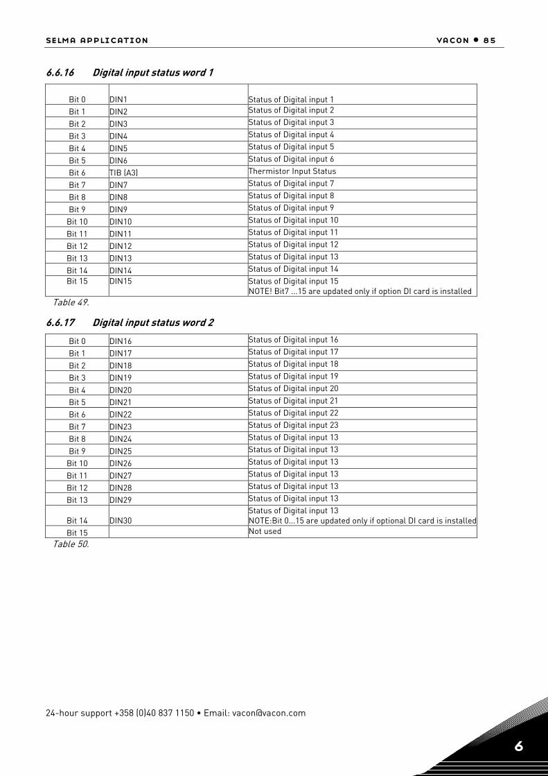
selma application vacon • 85
24-hour support +358 (0)40 837 1150 • Email: [email protected] 6
6.6.16 Digital input status word 1
Bit 0 DIN1 Status of Digital input 1
Bit 1 DIN2 Status of Digital input 2
Bit 2 DIN3 Status of Digital input 3
Bit 3 DIN4 Status of Digital input 4
Bit 4 DIN5 Status of Digital input 5
Bit 5 DIN6 Status of Digital input 6
Bit 6 TIB (A3) Thermistor Input Status
Bit 7 DIN7 Status of Digital input 7
Bit 8 DIN8 Status of Digital input 8
Bit 9 DIN9 Status of Digital input 9
Bit 10 DIN10 Status of Digital input 10
Bit 11 DIN11 Status of Digital input 11
Bit 12 DIN12 Status of Digital input 12
Bit 13 DIN13 Status of Digital input 13
Bit 14 DIN14 Status of Digital input 14 Bit 15 DIN15 Status of Digital input 15
NOTE! Bit7 ...15 are updated only if option DI card is installed Table 49.
6.6.17 Digital input status word 2
Bit 0 DIN16 Status of Digital input 16
Bit 1 DIN17 Status of Digital input 17
Bit 2 DIN18 Status of Digital input 18
Bit 3 DIN19 Status of Digital input 19
Bit 4 DIN20 Status of Digital input 20
Bit 5 DIN21 Status of Digital input 21
Bit 6 DIN22 Status of Digital input 22
Bit 7 DIN23 Status of Digital input 23
Bit 8 DIN24 Status of Digital input 13
Bit 9 DIN25 Status of Digital input 13
Bit 10 DIN26 Status of Digital input 13
Bit 11 DIN27 Status of Digital input 13
Bit 12 DIN28 Status of Digital input 13
Bit 13 DIN29 Status of Digital input 13
Bit 14 DIN30 Status of Digital input 13 NOTE:Bit 0...15 are updated only if optional DI card is installed
Bit 15 Not used
Table 50.
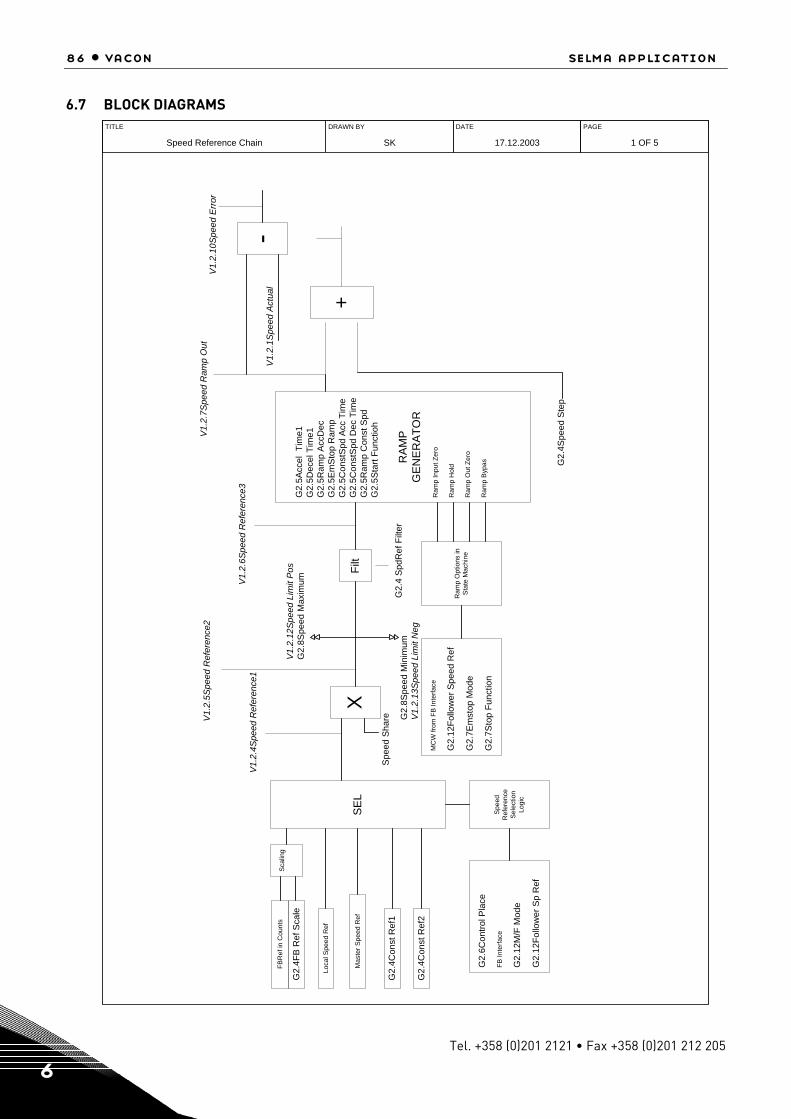
86 • vacon selma application
Tel. +358 (0)201 2121 • Fax +358 (0)201 212 205 6
6.7 BLOCK DIAGRAMS
DRAWN BY
SK
DATE
17.12.2003
PAGE
1 OF 5
TITLE
Speed Reference Chain
Sca
ling
FBR
ef in
Cou
nts
G2.
4FB
Ref
Sca
le
SE
L
Loca
l Spe
ed R
ef
Mas
ter S
peed
Ref
G2.
4Con
st R
ef1
G2.
4Con
st R
ef2
X
V1.
2.4S
peed
Ref
eren
ce1
Filt
V1.
2.5S
peed
Ref
eren
ce2
V1.
2.12
Spe
ed L
imit
Pos
G2.
8Spe
ed M
axim
um
G2.
8Spe
ed M
inim
umV
1.2.
13S
peed
Lim
it N
eg
Spe
ed S
hare
G2.
5Acc
el T
ime1
G2.
5Dec
el T
ime1
G2.
5Ram
p A
ccD
ecG
2.5E
mS
top
Ram
pG
2.5C
onst
Spd
Acc
Tim
eG
2.5C
onst
Spd
Dec
Tim
eG
2.5R
amp
Con
st S
pdG
2.5S
tart
Func
tioh
RA
MP
GE
NE
RA
TOR
Ram
p In
put Z
ero
Ram
p H
old
Ram
p O
ut Z
ero
Ram
p B
ypas
Ram
p O
ptio
ns in
Sta
te M
achi
ne
+
V1.
2.7S
peed
Ram
p O
ut
G2.
4Spe
ed S
tep
V1.
2.6S
peed
Ref
eren
ce3
Spe
edR
efer
ence
Sel
ectio
nLo
gic
-
V1.
2.10
Spe
ed E
rror
MC
W fr
om F
B In
terfa
ce
G2.
12Fo
llow
er S
peed
Ref
G2.
7Em
stop
Mod
e
G2.
7Sto
p Fu
nctio
nG
2.6C
ontro
l Pla
ce
FB In
terfa
ce
G2.
12M
/F M
ode
G2.
12Fo
llow
er S
p R
ef
V1.
2.1S
peed
Act
ual
G2.
4 S
pdR
ef F
ilter
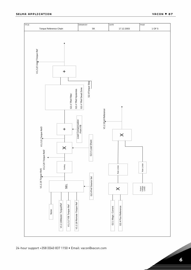
selma application vacon • 87
24-hour support +358 (0)40 837 1150 • Email: [email protected] 6
DRAWN BY
SK
DATE
17.12.2003
PAGE
1 OF 5
TITLE
Torque Reference Chain
SE
L
Non
e
V1.
2.16
Mas
ter T
orqu
eRef
V1.
2.17
FB
Tor
que
Ref
V1.
2.18
Rem
ote
Torq
ue R
ef
Sca
ling
G2.
4Tre
f Sou
rce
Sel
V1.
2.19
Tor
que
Ref
1
X
V1.
2.20
Tor
que
Ref
2
G2.
4 TR
ef F
ilter
G2.
4 TR
ef H
yste
risis
G2.
4 TR
ef D
ead
Zone
V1.
2.21
Tor
que
Ref
3
+
G2.
4Tor
que
Ste
p
V1.
2.22
Use
d To
rque
Ref
XG
2.1
Mag
n. C
urre
nt
G2.
4 Fl
ux R
efer
ence
Rat
e Li
mite
r
X
Out
put
Vol
tage
Lim
iter
Rat
e Li
mite
r
V1.
2.33
Id R
efer
ence
G2.
4 Lo
ad S
hare
+
Load
Com
pens
atio
nFr
om F
B
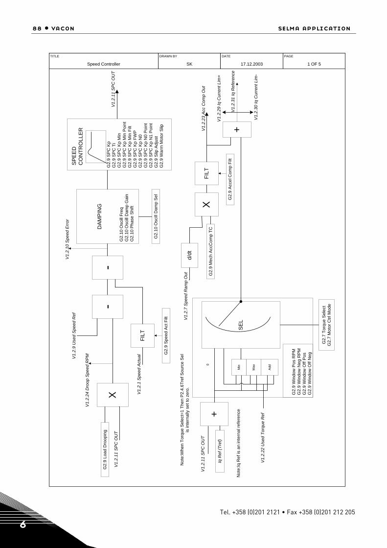
88 • vacon selma application
Tel. +358 (0)201 2121 • Fax +358 (0)201 212 205 6
DRAWN BY
SK
DATE
17.12.2003
PAGE
1 OF 5
TITLE
Speed Controller
FILT
V1.
2.1
Spe
ed A
ctua
l G2.
9 S
peed
Act
Filt
-D
AM
PIN
G
G2.
10 O
scill
Fre
qG
2.10
Osc
ill D
amp
Gai
nG
2.10
Pha
se S
hift
G2.
10 O
scill
Dam
p S
el
G2.
9 S
PC
Kp
G2.
9 S
PC
Ti
G2.
9 S
PC
Kp
Min
G2.
9 S
PC
Kp
Min
Poi
ntG
2.9
SP
C K
p M
in F
iltG
2.9
SP
C K
p FW
PG
2.9
SP
C K
p N
0G
2.9
SP
C K
p N
0 P
oint
G2.
9 S
PC
Kp
N1
Poi
ntG
2.9
Slip
Adj
ust
G2.
9 W
arm
Mot
or S
lip
SP
EE
DC
ON
TRO
LLE
R
V1.
2.10
Spe
ed E
rror
V1.
2.11
SP
C O
UT
XG
2.9
Mec
h A
ccC
omp
TCFI
LT
G2.
9 A
ccel
Com
p Fi
lt
+V1.
2.23
Acc
Com
p O
ut
V1.
2.31
Iq R
efer
ence
V1.
2.29
Iq C
urre
nt L
im+
V1.
2.30
Iq C
urre
nt L
im-
Not
e:W
hen
Torq
ue S
elec
t=1
Then
P2.
4.6T
ref S
ourc
e S
elis
inte
rnal
ly s
et to
zer
o.
V1.
2.11
SP
C O
UT
+
Add
0
Iq R
ef (T
ref)
V1.
2.22
Use
d To
rque
Ref
SE
LM
in
Max
G2.
9 W
indo
w P
os R
PM
G2.
9 W
indo
w N
eg R
PM
G2.
9 W
indo
w O
ff P
osG
2.9
Win
dow
Off
Neg
G2.
7 To
rque
Sel
ect
G2.
7 M
otor
Ctrl
Mod
e
d/dt
V1.
2.7
Spe
ed R
amp
Out
Not
e:Iq
Ref
is a
n in
tern
al re
fere
nce
XG
2.9
Load
Dro
opin
g-
V1.
2.9
Use
d S
peed
Ref
V1.
2.24
Dro
op S
peed
RP
M
V1.
2.11
SP
C O
UT
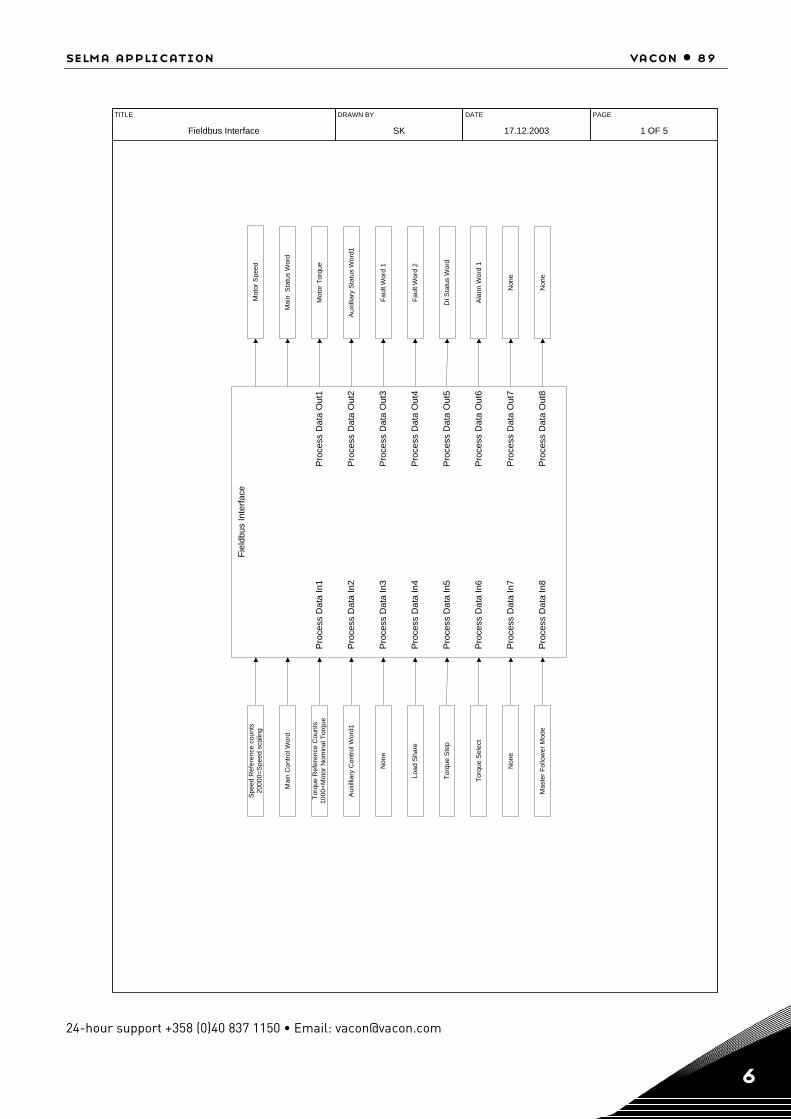
selma application vacon • 89
24-hour support +358 (0)40 837 1150 • Email: [email protected] 6
DRAWN BY
SK
DATE
17.12.2003
PAGE
1 OF 5
TITLE
Fieldbus Interface
Fiel
dbus
Inte
rface
Pro
cess
Dat
a In
1
Pro
cess
Dat
a In
2
Pro
cess
Dat
a In
3
Pro
cess
Dat
a In
4
Pro
cess
Dat
a In
5
Pro
cess
Dat
a In
6
Pro
cess
Dat
a In
7
Pro
cess
Dat
a In
8
Pro
cess
Dat
a O
ut1
Pro
cess
Dat
a O
ut2
Pro
cess
Dat
a O
ut3
Pro
cess
Dat
a O
ut4
Pro
cess
Dat
a O
ut5
Pro
cess
Dat
a O
ut6
Pro
cess
Dat
a O
ut7
Pro
cess
Dat
a O
ut8
Non
eN
one
Mot
or S
peed
Spe
ed R
efer
ence
cou
nts
2000
0=S
peed
sca
ling
Mai
n C
ontro
l Wor
dM
ain
Sta
tus
Wor
d
Mot
or T
orqu
eTo
rque
Ref
eren
ce C
ount
s10
00=M
otor
Nom
inal
Tor
que
Aux
illia
ry S
tatu
s W
ord1
Aux
illia
ry C
ontro
l Wor
d1
Faul
t Wor
d 1
Non
e
Faul
t Wor
d 2
Load
Sha
re
DI S
tatu
s W
ord
Torq
ue S
tep
Ala
rm W
ord
1To
rque
Sel
ect
Non
eM
aste
r Fol
low
er M
ode
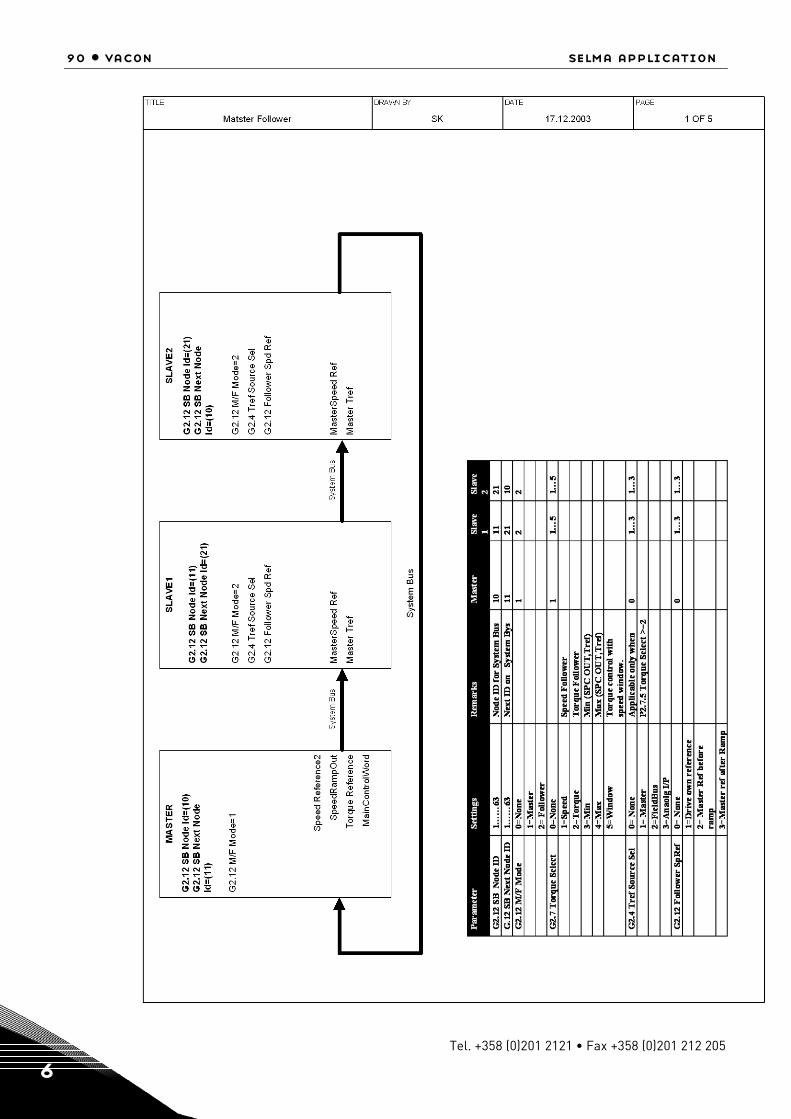
90 • vacon selma application
Tel. +358 (0)201 2121 • Fax +358 (0)201 212 205 6
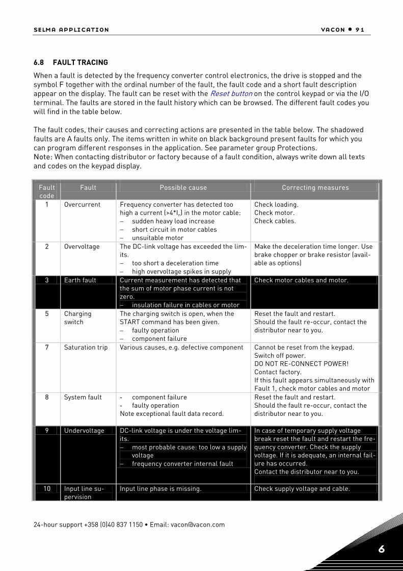
selma application vacon • 91
24-hour support +358 (0)40 837 1150 • Email: [email protected] 6
6.8 FAULT TRACING
When a fault is detected by the frequency converter control electronics, the drive is stopped and the symbol F together with the ordinal number of the fault, the fault code and a short fault description appear on the display. The fault can be reset with the Reset button on the control keypad or via the I/O terminal. The faults are stored in the fault history which can be browsed. The different fault codes you will find in the table below. The fault codes, their causes and correcting actions are presented in the table below. The shadowed faults are A faults only. The items written in white on black background present faults for which you can program different responses in the application. See parameter group Protections. Note: When contacting distributor or factory because of a fault condition, always write down all texts and codes on the keypad display.
Fault code
Fault Possible cause Correcting measures
1 Overcurrent Frequency converter has detected too high a current (>4*In) in the motor cable: − sudden heavy load increase − short circuit in motor cables − unsuitable motor
Check loading. Check motor. Check cables.
2 Overvoltage The DC-link voltage has exceeded the lim-its. − too short a deceleration time − high overvoltage spikes in supply
Make the deceleration time longer. Use brake chopper or brake resistor (avail-able as options)
3 Earth fault Current measurement has detected that the sum of motor phase current is not zero. − insulation failure in cables or motor
Check motor cables and motor.
5 Charging switch
The charging switch is open, when the START command has been given. − faulty operation − component failure
Reset the fault and restart. Should the fault re-occur, contact the distributor near to you.
7 Saturation trip Various causes, e.g. defective component Cannot be reset from the keypad. Switch off power. DO NOT RE-CONNECT POWER! Contact factory. If this fault appears simultaneously with Fault 1, check motor cables and motor
8 System fault - component failure - faulty operation Note exceptional fault data record.
Reset the fault and restart. Should the fault re-occur, contact the distributor near to you.
9 Undervoltage DC-link voltage is under the voltage lim-its. − most probable cause: too low a supply
voltage − frequency converter internal fault
In case of temporary supply voltage break reset the fault and restart the fre-quency converter. Check the supply voltage. If it is adequate, an internal fail-ure has occurred. Contact the distributor near to you.
10 Input line su-pervision
Input line phase is missing. Check supply voltage and cable.
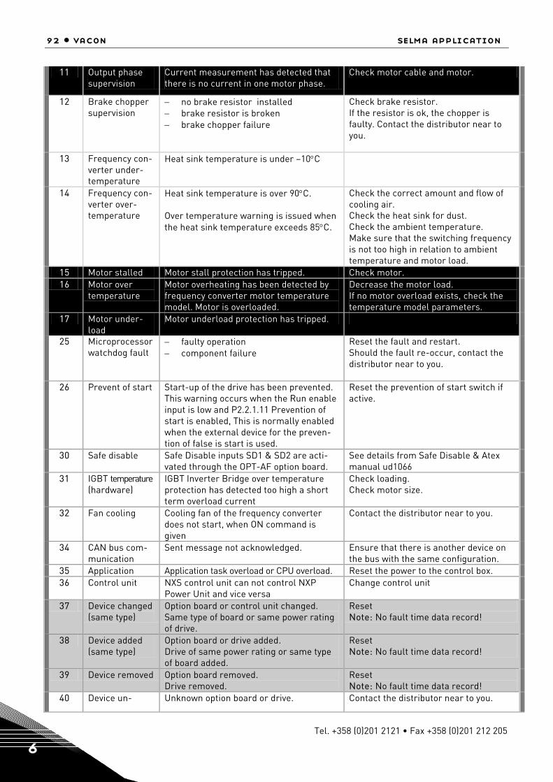
92 • vacon selma application
Tel. +358 (0)201 2121 • Fax +358 (0)201 212 205 6
11 Output phase supervision
Current measurement has detected that there is no current in one motor phase.
Check motor cable and motor.
12 Brake chopper supervision
− no brake resistor installed − brake resistor is broken − brake chopper failure
Check brake resistor. If the resistor is ok, the chopper is faulty. Contact the distributor near to you.
13 Frequency con-verter under-temperature
Heat sink temperature is under –10°C
14 Frequency con-verter over-temperature
Heat sink temperature is over 90°C. Over temperature warning is issued when the heat sink temperature exceeds 85°C.
Check the correct amount and flow of cooling air. Check the heat sink for dust. Check the ambient temperature. Make sure that the switching frequency is not too high in relation to ambient temperature and motor load.
15 Motor stalled Motor stall protection has tripped. Check motor. 16 Motor over
temperature Motor overheating has been detected by frequency converter motor temperature model. Motor is overloaded.
Decrease the motor load. If no motor overload exists, check the temperature model parameters.
17 Motor under-load
Motor underload protection has tripped.
25 Microprocessor watchdog fault
− faulty operation − component failure
Reset the fault and restart. Should the fault re-occur, contact the distributor near to you.
26 Prevent of start Start-up of the drive has been prevented. This warning occurs when the Run enable input is low and P2.2.1.11 Prevention of start is enabled, This is normally enabled when the external device for the preven-tion of false is start is used.
Reset the prevention of start switch if active.
30 Safe disable Safe Disable inputs SD1 & SD2 are acti-vated through the OPT-AF option board.
See details from Safe Disable & Atex manual ud1066
31 IGBT temperature (hardware)
IGBT Inverter Bridge over temperature protection has detected too high a short term overload current
Check loading. Check motor size.
32 Fan cooling Cooling fan of the frequency converter does not start, when ON command is given
Contact the distributor near to you.
34 CAN bus com-munication
Sent message not acknowledged. Ensure that there is another device on the bus with the same configuration.
35 Application Application task overload or CPU overload. Reset the power to the control box. 36 Control unit NXS control unit can not control NXP
Power Unit and vice versa Change control unit
37 Device changed (same type)
Option board or control unit changed. Same type of board or same power rating of drive.
Reset Note: No fault time data record!
38 Device added (same type)
Option board or drive added. Drive of same power rating or same type of board added.
Reset Note: No fault time data record!
39 Device removed Option board removed. Drive removed.
Reset Note: No fault time data record!
40 Device un- Unknown option board or drive. Contact the distributor near to you.

selma application vacon • 93
24-hour support +358 (0)40 837 1150 • Email: [email protected] 6
known
41 IGBT temperature IGBT inverter bridge overtemperature protection has detected too high a short term overload current
Check loading. Check motor size.
42 Brake resistor over tempera-ture
Brake resistor over temperature protec-tion has detected too heavy braking
Set the deceleration time longer. Use external brake resistor.
43 Encoder fault Note the exceptional fault data record. Additional codes: 1 = Encoder 1 channel A is missing 2 = Encoder 1 channel B is missing 3 = Both encoder 1 channels are missing 4 = Encoder reversed
Check encoder channel connections. Check the encoder board.
44 Device changed (different type)
Option board or control unit changed. Option board of different type or different power rating of drive.
Reset Note: No fault time data record! Note: Application parameter values re-stored to default.
45 Device added (different type)
Option board or drive added. Option board of different type or drive of different power rating added.
Reset Note: No fault time data record! Note: Application parameter values re-stored to default.
50 Analogue input Iin < 4mA (sel. signal range 4 to 20 mA)
Current at the analogue input is < 4mA. − control cable is broken or loose − signal source has failed
Check the current loop circuitry.
51 External fault Digital input fault. 52 Keypad com-
munication fault
The connection between the control key-pad and the frequency converter is bro-ken.
Check keypad connection and possible keypad cable.
53 Fieldbus fault The data connection between the fieldbus Master and the fieldbus board is broken
Check installation. If installation is correct contact the nearest Vacon distributor.
54 Slot fault Defective option board or slot Check board and slot. Contact the nearest Vacon distributor.
55 Follower com-munication
This fault can occur only in Follower drive P2.12.1 M/Fmode =2 (Follower). Follower drive is not able to receive data from Master drive on system bus(optical link).
Check the setting of P2.13.25 SBFault Delay. The default is 0.10sec. Check the optical link between MasterFollower and jumper settings on OPT-D2 board in Vacon option board manual. OPT-D2 board can be installed only in slot D or slot E.
56 PT100 Temp. overtemperatue
PT100(1) element/s has sensed overtem-perature.
Check the temperature of the part where the PT100 is mounted. Check parameters P2.2.2.3 to P2.2.2.6, P2.13.18 to P2.13.20.
57 ID run failure ID run could not be completed success-fully.
Check monitoring signal V1.1.19 ID run status to find out which part of the ID run is failed. Redo the ID run.

94 • vacon selma application
Tel. +358 (0)201 2121 • Fax +358 (0)201 212 205 6
58
Mechanical brake fault
Mechanical brake lifted signal is not re-ceived within time defined by P2.11.1 Brake life delay after the Run command. The digital input is selected by P2.2.6 Mo-tor brake acknowledgement OR Brake open signal is acknowledged when there is no run command given.
Check the parameters P2.13.28 Mechanical brake fault P2.2.6 Motor brake acknowledgement P2.11.1 Brake lift delay Check the Motor brake circuit.
59 Motor fan fault Motor fan acknowledgement is not re-ceived within 5 seconds after run com-mand.
Check P2.2.1.7 . Check motor fan connection.
61 Thermistor Thermistor overtemperature. Thermistor is connected to OPT-A3 board in slot B.
Check the temperature of the area where the thermistor is mounted. Check the connection of the thermistor to OPT-A3.
62 Run disabled Run Enable digital input is gone low. Check P2.2.1.9,P2.2.1.10. Reset the run enable input.
63 Emergency stop
DIN6 is inactive /low. Check the emergency stop push button connected to DIN6. Check P2.210 Emergency stop control.
64 Input SW Open The drive main power is switched off and DIN5 is inactive/low.
Check the main power switch of the drive. Check P2.2.8 Run Enable control as per the description in the manual.
Table 51. Fault codes
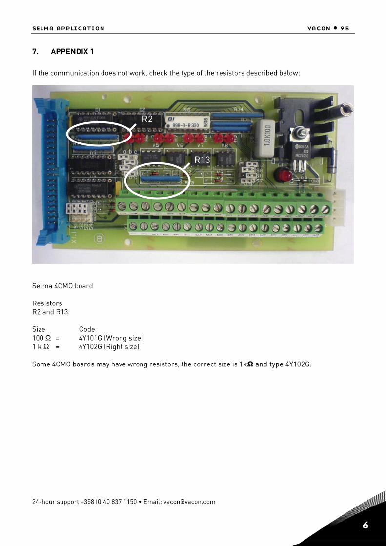
selma application vacon • 95
24-hour support +358 (0)40 837 1150 • Email: [email protected] 6
7. APPENDIX 1
If the communication does not work, check the type of the resistors described below:
Selma 4CMO board Resistors R2 and R13 Size Code 100 Ω = 4Y101G (Wrong size) 1 k Ω = 4Y102G (Right size) Some 4CMO boards may have wrong resistors, the correct size is 1kΩ and type 4Y102G.
R2
R13
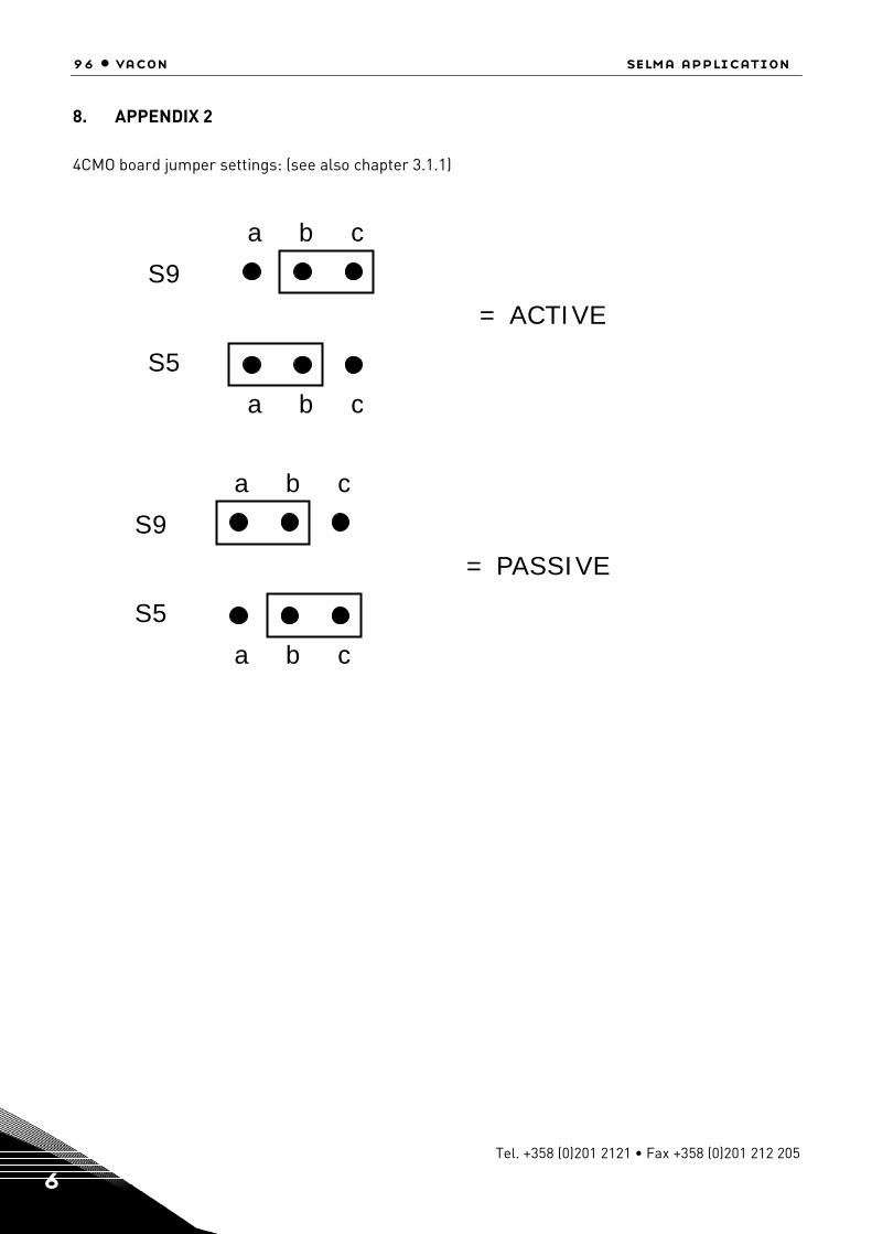
96 • vacon selma application
Tel. +358 (0)201 2121 • Fax +358 (0)201 212 205 6
8. APPENDIX 2
4CMO board jumper settings: (see also chapter 3.1.1)
S9
S5
= ACTIVE
a b c
a b c
S9
S5
= PASSIVE
a b c
a b c


Document ID:
Rev. A
Manual authoring:[email protected]
Vacon Plc.Runsorintie 765380 VaasaFinland
Subject to change without prior notice© 2011 Vacon Plc.
Find your nearest Vacon office on the Internet at:
www.vacon.com
Find your nearest Vacon service centre on the Extranet at:
www.extra.vacon.com