an00174-001 modbus tcp fieldbus option for … modbus tcp fieldbus option for motiflex ... (the...
TRANSCRIPT
© Baldor UK Ltd 2009
AN00174-001 Modbus TCP Fieldbus Option for MotiFlex e100.doc
1111 of of of of 22222222
Overview
The Baldor Modbus/TCP Fieldbus Option Card (FOC) for MotiFlex e100 allows the drive to provide
10/100 Mbit/s full/half duplex Modbus/TCP communications (up to 4 simultaneous connections).
Note: The Fieldbus Option must be plugged into option slot 1 on the MotiFlex e100.
Please refer to the MotiFlex Fieldbus Option Card Installation manual MN1954 for full connection
details and information about the various diagnostic LEDs fitted to the Fieldbus Option.
Typically the Fieldbus Option would be used as a ‘Gateway’ between a PLC (or other such client
device on Modbus/TCP) and a NextMove e100 (or other such device on Ethernet Powerlink). This
Application Note details how this configuration can be achieved.
The client must be capable of addressing the standard Modbus TCP Port (502) on the Fieldbus
Option.
The Fieldbus Option’s default IP address is 0.0.0.2, but this can be changed via WorkBench if
required.
Note: If the Modbus/TCP IP address is set identical to the EPL IP address it is
important not to directly connect the Modbus/TCP network to the EPL network.
The Fieldbus Option handles the transmission of data to and from the Modbus/TCP network. Data
items are stored in Application Data Instances (ADIs) of the Application Data Object (ADO)
maintained by the MotiFlex e100. This fieldbus data, both in and out of the drive, is 'mapped' to
the drive's standard Ethernet Powerlink (EPL) object dictionary entries. Since an EPL manager
node (MN) such as a NextMove e100 has access to all of the drive's object dictionary entries it
can therefore also access any fieldbus Process Data. The drive's objects can also be mapped to
EPL PDOs, allowing the MN to provide cyclic updates of fieldbus related data. The correlation
(mapping) between the drive's object numbers and the ADI numbers (and related Mint keywords)
is shown in the Fieldbus Option’s object dictionary which is listed in the Mint Help File that installs
with WorkBench v5.5.
The Modbus/TCP side of the Fieldbus Option allows for up to 512 bytes of Process Data (256 16-
bit registers) to be mapped in each direction (read/write), which corresponds to 128 32-bit
Process Data items. However, the number of Process Data items that can actually be mapped to
the MotiFlex e100 over EPL and also over Modbus/TCP is limited to 64 on each (64 transmit and
64 receive Process Data items on each of the networks). So this determines the maximum
amount of data that can be transferred between the two network segments.
Part Number/Ordering Information
The MotiFlex e100 Fieldbus Option Cards comprise a fieldbus module which must be fitted to a
carrier card. This two part construction allows a different fieldbus to be fitted at a later date
without changing the carrier card.
AN00174-001: Modbus/TCP Fieldbus Option for MotiFlex e100
© Baldor UK Ltd 2009
AN00174-001 Modbus TCP Fieldbus Option for MotiFlex e100.doc
2222 of of of of 22222222
A wide range of fieldbus modules are available (contact your local Baldor office or distributor for a
full list):
• Carrier card: OPT-MF-030
• DeviceNet: OPT-FB-001 (Anybus AB6201)
• PROFIBUS DP-V1: OPT-FB-002 (Anybus AB6200)
• EtherNet/IP: OPT-FB-004 (Anybus AB6214)
• Modbus/TCP: OPT-FB-005 (Anybus AB6213)
• PROFINET IO: OPT-FB-006 (Anybus AB6215)
Separate application notes are available on setting up these alternative Fieldbus Options.
Modbus/TCP Function Codes
The Modbus/TCP Fieldbus Option supports the following Modbus function codes:
• 1 - Read Coils
• 2 - Read Discrete Inputs
• 3 - Read holding Registers
• 4 - Read Input Registers
• 5 - Write Single Coil
• 6 - Write Single Register
• 15 - Write Multiple Coils
• 16 - Write Multiple Registers
• 23 - Read/Write Multiple Registers
• 43 - Read Device Identification
Modbus/TCP Register Implementations
The Modbus/TCP Holding (4x) Registers are mapped as follows:
Modbus Register Range Contents
0000 – 00FF hex (0 to 255 dec) Read Process Data (data written by PLC)
0100 – 01FF hex (256 to 511 dec) Write Process Data (data read by PLC)
0210 – FFFF hex (528 to 65535 dec) Application Data Instances (ADIs)
The Modbus/TCP Input (3x) Registers are mapped as follows:
Modbus Register Range Contents
0000 – 00FF hex (0 to 255 dec) Write Process Data (e.g. Input register 0 is
mapped to Modbus Register 0100 hex)
The Modbus/TCP Discrete Input (1x) Registers are mapped as follows:
Modbus Register Range Contents
0000 – 0FFF hex (0 to 4095 dec) Write Process Data (e.g. Discrete Input
register 0 is mapped to Modbus Register 0100
hex)
The Modbus/TCP Discrete Output (0x) Registers are mapped as follows:
Modbus Register Range Contents
0000 – 0FFF hex (0 to 4095 dec) Read Process Data (e.g. Discrete Output
register 0 is mapped to Modbus Register 0000
hex)

© Baldor UK Ltd 2009
AN00174-001 Modbus TCP Fieldbus Option for MotiFlex e100.doc
3333 of of of of 22222222
Configuring the Drive
Configuring the drive’s Modbus/TCP settings is very simple. Using WorkBench v5.5 Build 5621 or
later connect to your MotiFlex e100 drive (the drive must be running firmware build 5613 or
later).
Communications Settings
WorkBench will automatically detect which type of fieldbus module has been installed. Each
communication channel can be allocated a unique node address and baud rate (where
applicable).
In the case of Modbus/TCP the baud rate is fixed at 10/100Mbps and the default IP address is set
to 0.0.0.2.
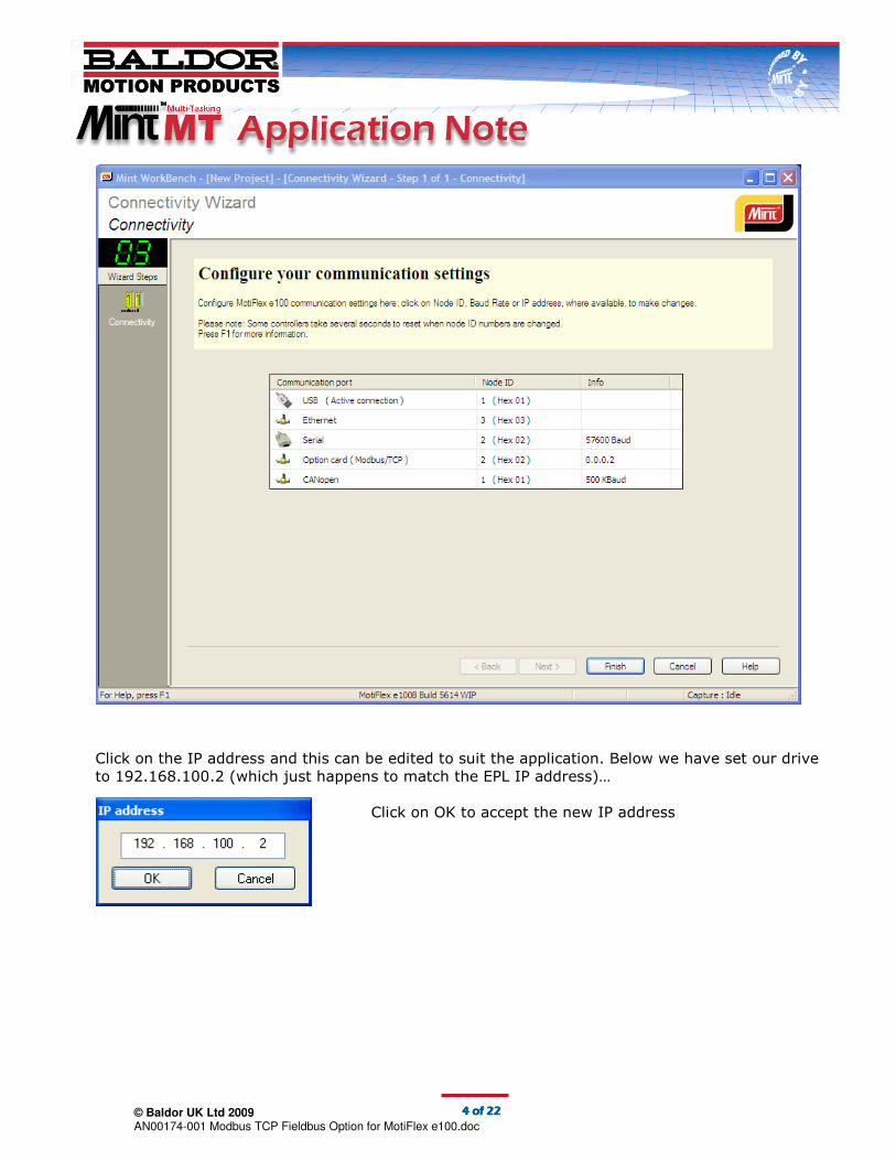
The IP Address can be set using the OPTIONCARDNETWORKADDRESS(1) keyword or by using the
Connectivity tool in Workbench. For this example a Node address of 02 has been used and a full
IP address of 192.168.100.2.
The IP address can be set at the command line using OPTIONCARDNETWORKADDRESS as
follows:
Or more easily, click on the Connectivity tool in the left hand tool bar of Workbench and click on
the Info box next to the Option Card (Modbus/TCP) port settings. Then type in the required IP
address as four separate octets. Please note that changing the Node ID will automatically change
the last octet of the IP address and vice versa. Press the Finish button to complete the process.
This setting will now be stored permanently as a drive parameter.
Any IP address can be used and it does not need to match the EPL IP address set on the drive.
© Baldor UK Ltd 2009
AN00174-001 Modbus TCP Fieldbus Option for MotiFlex e100.doc
4444 of of of of 22222222
Click on the IP address and this can be edited to suit the application. Below we have set our drive
to 192.168.100.2 (which just happens to match the EPL IP address)…
Click on OK to accept the new IP address

© Baldor UK Ltd 2009
AN00174-001 Modbus TCP Fieldbus Option for MotiFlex e100.doc
5555 of of of of 22222222
Process Data Configuration
Click on ‘System Configuration’ in the left hand toolbar. WorkBench will now display the setup
screens for the MotiFlex’s Device Configuration File (DCF).
The initial screen shows our EPL Node ID (set via the rotary switches on the front of the MotiFlex
drive – in our example 02 hex) and the Modbus/TCP Node ID (the last Octet of our IP address),
which is set to the same value. If we’ve configured a MotiFlex in the past we have the option to
open a saved DCF file or we can choose to start a new configuration. We’ll select this option –
Start New Configuration. Click on Next to continue.

© Baldor UK Ltd 2009
AN00174-001 Modbus TCP Fieldbus Option for MotiFlex e100.doc
6666 of of of of 22222222
WorkBench now displays a screen allowing the user to configure EPL side Process Data mappings
in and out of the drive. As the comments on this screen detail, these mappings should be
performed on the EPL network manager node (i.e. NextMove e100) if there is one. As we’re going
to want to pass data to/from a NextMove e100 as part of this Application Note we will detail later
how to configure the NextMove e100 to do this so for now we can skip this page of the drive
setup and move onto the next page – Click on Next.
WorkBench now displays the mapped Process Data objects for the Modbus/TCP side of the
fieldbus interface:
This screen allows the user to configure how often the drive updates the drive side of the
interface (i.e. the Internal data). How often the Modbus/TCP master (e.g. PLC) reads/writes
the Modbus/TCP side of the interface is down to how the Modbus/TCP scanner/client is
configured.
We will leave the Internal Update Rate set to its default of 1ms.
The screen also shows how many of the possible 64 Process Data items (in each direction) we
have allocated (as we’ve just started a new configuration these are both set to zero initially).

© Baldor UK Ltd 2009
AN00174-001 Modbus TCP Fieldbus Option for MotiFlex e100.doc
7777 of of of of 22222222
There are two icons for mapped Process Data:
• Receive – data sent from the PLC to the drive
• Transmit – data sent from the drive to the PLC
Click on the dropdown to see the full list of pre-defined
objects (the Custom object can be used to access a
wider range of drive objects – see the Mint Help File for
full details of the drive’s object dictionary).
For the purposes of this Application Note we are going
to map two NetData Process Data Objects from the PLC
to the drive.
Later on we will map these two NetData values to our
NextMove e100 so effectively the PLC is able to write
two data values to the NextMove using the drive as a
Gateway.
Select NetData from the list.
Double click the Receive icon (or single
click and then click on the yellow +
button). WorkBench now displays a dialog
allowing the user to select where the first
PDO data received from the PLC should be mapped to on the drive:

© Baldor UK Ltd 2009
AN00174-001 Modbus TCP Fieldbus Option for MotiFlex e100.doc
8888 of of of of 22222222
There are 1000 NetData channels available (0 to 999). We will start our mappings from
Channel 1…
Click on ‘OK’. WorkBench will now update the list of Receive and Transmit Process Data items…
Repeat this process adding three more channels of NetData (Channels 2 to 4) to the Receive
Process Data.
The order of these entries is important. The first item in the list will correspond to the lowest
register address in the Read Process data area (0000 hex).
NetData is a 32-bit value so each NetData object will consume two 16-bit registers. How this
data is encoded is down to the Modbus/TCP client (e.g. the PLC). The client can load these
registers in a number of different formats (e.g. LONG, FLOAT).
The read the correct data values on the drive (and NextMove e100 once the data is mapped
onwards) you must be aware of the data format used by the client. We will illustrate this
further later in the Application Note.
The Up/Down arrows to the right of the mapped Process Data list allow you to modify the
order of the configured Process data if necessary.
Double-click the Transmit icon to configure the Process Data the PLC is going to read from the
drive. Repeat a similar process to that used to configure the receive data. Add two further
NetData objects (channels 3 and 4).
Your dialog should look like this:
Again the order of the Transmit data is important. NetData
Channel 3 will map to the first Modbus register in the Write
Process data area (0100 hex).

© Baldor UK Ltd 2009
AN00174-001 Modbus TCP Fieldbus Option for MotiFlex e100.doc
9999 of of of of 22222222
The Mint Help file details the data types and sizes for all the drive parameters/objects…
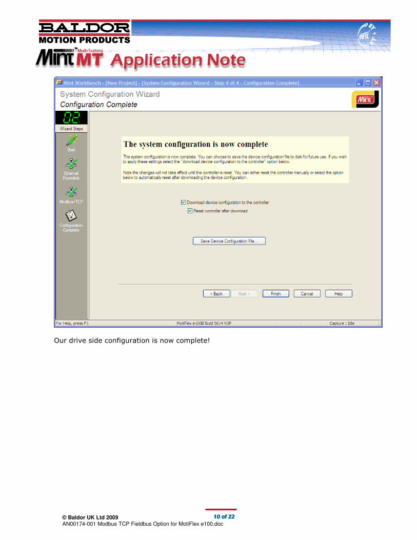
We have now finished mapping all the Process Data we need for our example, so click on the
‘Next’ button.
WorkBench now gives us an option to save our Device Configuration File (should we need to
repeat this setup for additional drives or future machines). Check ‘Download device
configuration to the controller’ and ‘Reset controller after download’ and click on Finish to
transfer the configuration to the MotiFlex and automatically restart it.
© Baldor UK Ltd 2009
AN00174-001 Modbus TCP Fieldbus Option for MotiFlex e100.doc
10101010 of of of of 22222222
Our drive side configuration is now complete!

© Baldor UK Ltd 2009
AN00174-001 Modbus TCP Fieldbus Option for MotiFlex e100.doc
11111111 of of of of 22222222
Physically adding a MotiFlex e100 drive to a Modbus/TCP network
The diagram below indicates the pin-out of the Modbus/TCP connector on the edge of the
Modbus/TCP Fieldbus Option card (remember this card MUST be plugged into slot 1 of the
MotiFlex drive):
A ‘crossover’ CAT5e (screened) Ethernet cable should be used to connect the Fieldbus Option to
the Modbus/TCP network.
Once the drive has been physically connected to the network it is ready for communication with
the Modbus/TCP client (e.g. PLC). As mentioned previously, the default drive’s Modbus/TCP
address is 0.0.0.2, which can be changed using the Connectivity Wizard in Workbench.
Refer to MotiFlex Fieldbus Option Card Installation Manual MN1954 for full details on the physical
installation of the option card/module including information about the status LEDs on the card.
Testing Read and Write Data
For the purposes of this Application Note we have used a PC based Modbus/TCP client (a demo
application from Automated Solutions called MiniHMI that illustrates the use of their Modbus/TCP
ActiveX control). See http://www.automatedsolutions.com for further details on their range of
controls. The Modbus/TCP ActiveX and MiniHMI application is available to trial free for 30 days.
The communication parameters for the TCP connection were set as follows:

© Baldor UK Ltd 2009
AN00174-001 Modbus TCP Fieldbus Option for MotiFlex e100.doc
12121212 of of of of 22222222
The MiniHMI application allows the user to Read and Write all of the various Modbus register
types.
For the purpose of this Application Note we have used the Read Registers and Write Registers
pages to illustrate the operation of the MotiFlex Fieldbus Option…
Reading Process Data
Using the Read Registers page of the MiniHMI application we set the following parameters:
Before we click on a button to initiate the read we need to load some data into the relevant
NetData locations on the MotiFlex drive…
Start WorkBench v5.5, start a new project and connect to the MotiFlex e100 drive. Select the Edit
& Debug icon in the left hand toolbar.
Now select the NetData tab in the Spy window on the right hand side of the WorkBench screen…
Click on the Add.. button and add a Watch to NetData Channel/Index 1 (Data Type: Integer)
Repeat this process for Channels/Indexes 2, 3 and 4.
We selected Output (Holding) registers as the
memory type as these are the registers that PDO
data is mapped to (see Modbus/TCP Register
Implementations earlier).
Modbus register 256 is the first register in the
Write Process Data area (data read by the client).
We have set the quantity of registers to read to 2
(i.e. registers 256 and 257).
Note that the data format initially is INTEGER (i.e. 16 bit data) and the addressing is zero based.

© Baldor UK Ltd 2009
AN00174-001 Modbus TCP Fieldbus Option for MotiFlex e100.doc
13131313 of of of of 22222222
Your Spy Window should look something like this...
Now we returned to the MiniHMI application and clicked on the ‘Synch Read’ button to initiate a
read of the Modbus registers. The following data appeared in the data view area…
Next we changed the Quantity of registers to read to 4 and clicked on ‘Synch Read’ again…
We can see from these results that the data is loaded into the least significant word and the
upper word is not used when using Integer (16-bit) data.
Next we changed the data format to LONG (32-bit integer) and the Address/Quantity to 256 and
2 respectively…
NetData Channels 3 and 4 are the Transmit PDOs
so use the WorkBench Spy Window to ‘poke’ some
Integer range (+/- 32767) data into these two
locations (highlight element 3 or 4 in the
WorkBench Net Data Watch Window and enter a
new value at the bottom of the Spy Window (click
on the Green Tick to accept this).
We entered 1234 for NetData 3 and 5678 for
NetData 4…
Note that our value in NetData 3 (1234) consumed two
Modbus registers. This is because NetData is a 32-bit
value and the Modbus registers area all 16-bit.
Now we can see the value for NetData 3 in register 256
and the value for NetData 4 in register 258. If we try to
read a value greater/less than +/-32767 then the data
becomes ‘corrupted’.

© Baldor UK Ltd 2009
AN00174-001 Modbus TCP Fieldbus Option for MotiFlex e100.doc
14141414 of of of of 22222222
Now when we read the Process Data from the drive the data view area displayed the following
result (note that the MiniHMI software automatically displays only registers 256 and 258)…
Because we are now using 32-bit data we are able to load full 32-bit values into our Integer
NetData values on the drive….
Using Modbus/TCP it is also possible to transfer floating point data. Switch to WorkBench v5.5
and edit the NetData spy entries for Channels 3 and 4 so their data type becomes Float.
Now enter some floating point data via the Spy window (we used 123.45 and -123.45)…
Writing Process Data
Using the Write Registers page of the MiniHMI application we set the following parameters:
Now change the Data Format in the MiniHMI application
to FLOAT (leaving the Address and Quantity set to 256
and 2 respectively). Click on the Synch Read button and
the client now displays the correct floating point values
in registers 256 and 258…
We selected Multiple (Holding) registers as the
memory type as these are the registers that PDO
data is mapped to (see Modbus/TCP Register
Implementations earlier).
Modbus register 0 is the first register in the Read
Process Data area (data written by the client). We
have set the quantity of registers to write to 4
(i.e. registers 0 to 3). We know from our read
tests 4 registers will be needed to write 2 values.
Note that the data format initially is INTEGER (i.e.
16 bit data) and the addressing is zero based.
© Baldor UK Ltd 2009
AN00174-001 Modbus TCP Fieldbus Option for MotiFlex e100.doc
15151515 of of of of 22222222
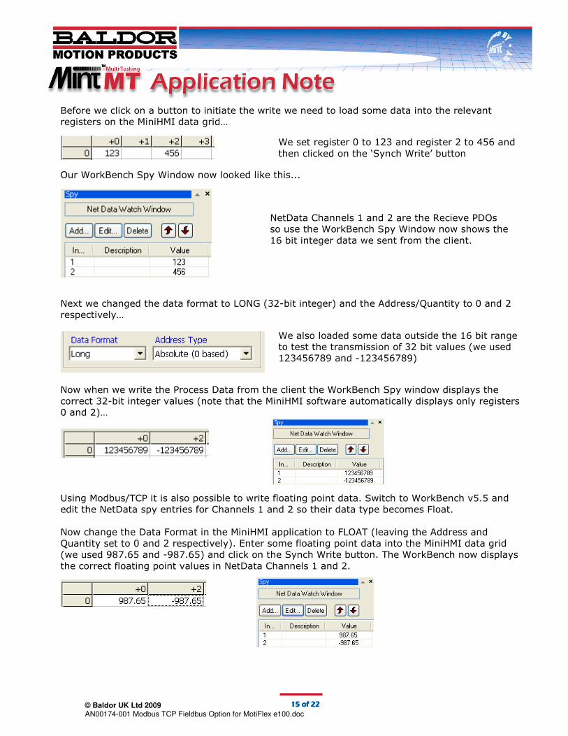
Before we click on a button to initiate the write we need to load some data into the relevant
registers on the MiniHMI data grid…
Our WorkBench Spy Window now looked like this...
Next we changed the data format to LONG (32-bit integer) and the Address/Quantity to 0 and 2
respectively…
Now when we write the Process Data from the client the WorkBench Spy window displays the
correct 32-bit integer values (note that the MiniHMI software automatically displays only registers
0 and 2)…
Using Modbus/TCP it is also possible to write floating point data. Switch to WorkBench v5.5 and
edit the NetData spy entries for Channels 1 and 2 so their data type becomes Float.
Now change the Data Format in the MiniHMI application to FLOAT (leaving the Address and
Quantity set to 0 and 2 respectively). Enter some floating point data into the MiniHMI data grid
(we used 987.65 and -987.65) and click on the Synch Write button. The WorkBench now displays
the correct floating point values in NetData Channels 1 and 2.
NetData Channels 1 and 2 are the Recieve PDOs
so use the WorkBench Spy Window now shows the
16 bit integer data we sent from the client.
We set register 0 to 123 and register 2 to 456 and
then clicked on the ‘Synch Write’ button
We also loaded some data outside the 16 bit range
to test the transmission of 32 bit values (we used
123456789 and -123456789)

© Baldor UK Ltd 2009
AN00174-001 Modbus TCP Fieldbus Option for MotiFlex e100.doc
16161616 of of of of 22222222
Mapping the Data to a NextMove e100
If you’ve followed this Application Note so far (and you have a Modbus/TCP client to use) then
you will have two process data objects being sent from the client/PLC to the MotiFlex drive
(mapped as NetData channels) and two process data objects being read by the client/PLC from
the MotiFlex drive (mapped as NetData channels).
The remainder of the Application Note shows how this data can be passed onto a NextMove e100
(via Ethernet Powerlink), effectively turning the drive into a Gateway between a Modbus/TCP
network and the Ethernet Powerlink network.
The diagram below illustrates this:
To achieve this transfer of data we must add the MotiFlex drive to the NextMove e100’s Device
Configuration File (DCF) and include the NetData channels in the list of additional Process Data to
be mapped between the NextMove and MotiFlex on the EPL network.
PLC with Modbus/TCP
MotiFlex
e100 Drive
with
Modbus/TCP
Fieldbus
Option
NextMove e100 (EPL Node 240)
NetData 1,2
NetData 3,4
Modbus/TCP
NetData 1,2
NetData 3,4
Ethernet Powerlink
© Baldor UK Ltd 2009
AN00174-001 Modbus TCP Fieldbus Option for MotiFlex e100.doc
17171717 of of of of 22222222
Mapping EPL Data
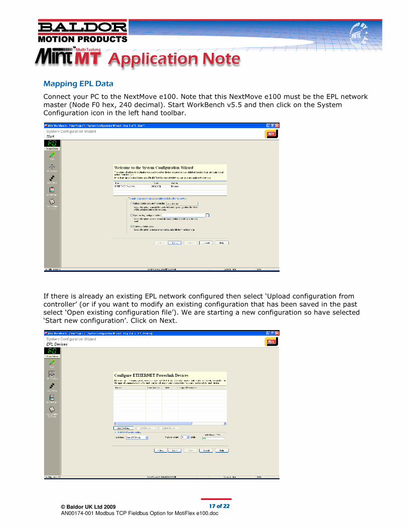
Connect your PC to the NextMove e100. Note that this NextMove e100 must be the EPL network
master (Node F0 hex, 240 decimal). Start WorkBench v5.5 and then click on the System
Configuration icon in the left hand toolbar.
If there is already an existing EPL network configured then select ‘Upload configuration from
controller’ (or if you want to modify an existing configuration that has been saved in the past
select ‘Open existing configuration file’). We are starting a new configuration so have selected
‘Start new configuration’. Click on Next.
© Baldor UK Ltd 2009
AN00174-001 Modbus TCP Fieldbus Option for MotiFlex e100.doc
18181818 of of of of 22222222
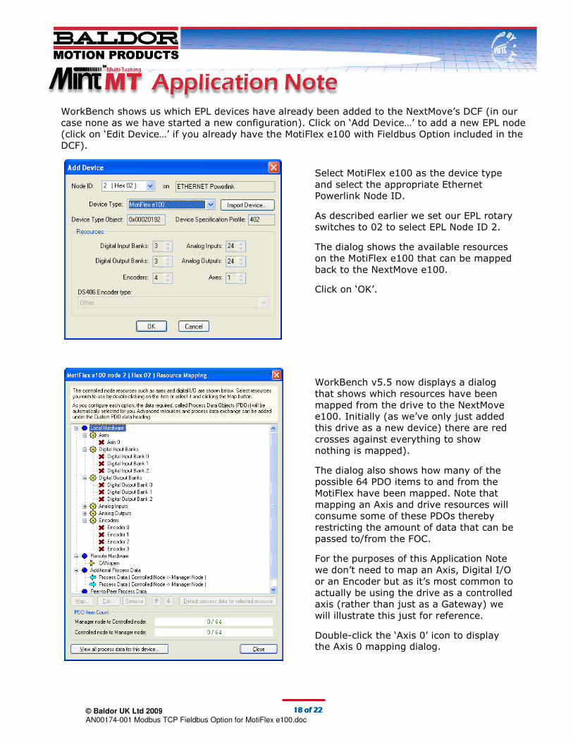
WorkBench shows us which EPL devices have already been added to the NextMove’s DCF (in our
case none as we have started a new configuration). Click on ‘Add Device…’ to add a new EPL node
(click on ‘Edit Device…’ if you already have the MotiFlex e100 with Fieldbus Option included in the
DCF).
Select MotiFlex e100 as the device type
and select the appropriate Ethernet
Powerlink Node ID.
As described earlier we set our EPL rotary
switches to 02 to select EPL Node ID 2.
The dialog shows the available resources
on the MotiFlex e100 that can be mapped
back to the NextMove e100.
Click on ‘OK’.
WorkBench v5.5 now displays a dialog
that shows which resources have been
mapped from the drive to the NextMove
e100. Initially (as we’ve only just added
this drive as a new device) there are red
crosses against everything to show
nothing is mapped).
The dialog also shows how many of the
possible 64 PDO items to and from the
MotiFlex have been mapped. Note that
mapping an Axis and drive resources will
consume some of these PDOs thereby
restricting the amount of data that can be
passed to/from the FOC.
For the purposes of this Application Note
we don’t need to map an Axis, Digital I/O
or an Encoder but as it’s most common to
actually be using the drive as a controlled
axis (rather than just as a Gateway) we
will illustrate this just for reference.
Double-click the ‘Axis 0’ icon to display the Axis 0 mapping dialog.
© Baldor UK Ltd 2009
AN00174-001 Modbus TCP Fieldbus Option for MotiFlex e100.doc
19191919 of of of of 22222222
Now we’ve mapped the axis the Resource Mapping dialog will show a green tick against Axis 0
and indicate in brackets which axis this has been mapped to on the NextMove…
The dialog also indicates that some Process Data associated with Manager Profiled operation of
the axis has been configured (we don’t need to look at this in detail for this Application Note).
Scroll down the Resource Mapping dialog until you find the ‘Additional Process Data’ section. This
is the section we need to edit…
There are two elements to this section:
• Process Data (Controlled Node<-Manager Node) – this is the Process Data that is to be
passed from the NextMove e100 to the drive (in our case this corresponds to NetData
Channels 3 and 4 which we want to pass from the NextMove e100 to the client/PLC
ultimately – via the MotiFlex Fieldbus Option)
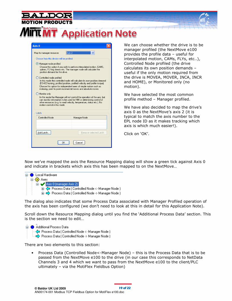
We can choose whether the drive is to be
manager profiled (the NextMove e100
provides the profile data – useful for
interpolated motion, CAMs, FLYs, etc..),
Controlled Node profiled (the drive
calculates its own position demands –
useful if the only motion required from
the drive is MOVEA, MOVER, INCA, INCR
and HOME), or Monitored only (no
motion).
We have selected the most common
profile method – Manager profiled.
We have also decided to map the drive’s
axis 0 as the NextMove’s axis 2 (it is
typical to match the axis number to the
EPL node ID as it makes tracking which
axis is which much easier!).
Click on ‘OK’.
© Baldor UK Ltd 2009
AN00174-001 Modbus TCP Fieldbus Option for MotiFlex e100.doc
20202020 of of of of 22222222
• Process Data (Controlled Node->Manager Node) – this is the Process Data that is to be
passed to the NextMove e100 from the drive (in our case this corresponds to NetData
Channels 1 and 2 which we want to pass from the client/PLC to the NextMove e100 via the
MotiFlex Fieldbus Option
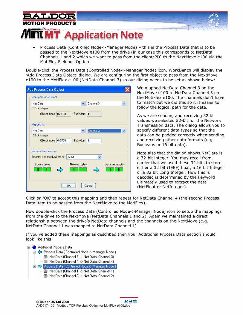
Double-click the Process Data (Controlled Node<-Manager Node) icon. WorkBench will display the
‘Add Process Data Object’ dialog. We are configuring the first object to pass from the NextMove
e100 to the MotiFlex e100 (NetData Channel 3) so our dialog needs to be set as shown below:
Click on ‘OK’ to accept this mapping and then repeat for NetData Channel 4 (the second Process
Data item to be passed from the NextMove to the MotiFlex).
Now double-click the Process Data (Controlled Node->Manager Node) icon to setup the mappings
from the drive to the NextMove (NetData Channels 1 and 2). Again we maintained a direct
relationship between the drive’s NetData channels and the channels on the NextMove (e.g.
NetData Channel 1 was mapped to NetData Channel 1).
If you’ve added these mappings as described then your Additional Process Data section should
look like this:
We mapped NetData Channel 3 on the
NextMove e100 to NetData Channel 3 on
the MotiFlex e100. The channels don’t have
to match but we did this so it is easier to
follow the logical path for the data.
As we are sending and receiving 32 bit
values we selected 32-bit for the Network
Transmission data. The dialog allows you to
specify different data types so that the
data can be padded correctly when sending
and receiving other data formats (e.g.
Booleans or 16 bit data).
Note also that the dialog shows NetData is
a 32-bit integer. You may recall from
earlier that we used these 32 bits to store
either a 32 bit (IEEE) float, a 16 bit Integer
or a 32 bit Long Integer. How this is
decoded is determined by the keyword
ultimately used to extract the data (NetFloat or NetInteger).

© Baldor UK Ltd 2009
AN00174-001 Modbus TCP Fieldbus Option for MotiFlex e100.doc
21212121 of of of of 22222222
Click on ‘Close’ to shut the Resource Mapping dialog.
WorkBench now shows that a MotiFlex e100 at EPL Node Address 2 has been added to the EPL
network and one axis has been mapped…
Keep clicking on ‘Next’ until the ‘System Configuration is Complete’ screen is reached…

© Baldor UK Ltd 2009
AN00174-001 Modbus TCP Fieldbus Option for MotiFlex e100.doc
22222222 of of of of 22222222
The ‘Save Device Configuration File…’ button can be used to save the DCF file to PC disk should
you need to save this for future use. Check the ‘Download device configuration to the controller’
and ‘Reset controller after download’ boxes and click on ‘Finish’ to transfer the DCF file to the
NextMove e100 and force it to restart.
Once the NextMove e100 has restarted you are ready to test if the client/PLC is able to read/write
data on the NextMove.
Testing the Exchange of Process Data
Whilst connected to the NextMove e100 use WorkBench v5.5 to select the ‘Net Data’ tab within
the Spy Window on the right hand side of the Edit & Debug area.
Click on the Add… button and add a Watch to NetData Channel 1 (Data Type Float). Repeat this
for NetaData Channel 2 (Float), NetData Channel 3 (Float) and NetData Channel 4 (Float).
Your Net Data Watch Window should look something like this…
Now poke some values into NetData Channels 3 and 4 on the NextMove (we entered 12.34 and
56.78 as you can see above).
Ask the Modbus client/PLC to read Modbus registers 256 and 258 and you should receive the
values entered for these two NetData channels.
Now using the Modbus/TCP client/PLC, write some Float data to Modbus registers 0 and 2 (i.e. the
first two floats). You should see these appear in the NextMove’s NetData Watch Window (as you
can see from above, we wrote the values 1.11 and 2.22).
Congratulations! You have now completed this Application Note. You can now see how simple it is
to exchange data in either direction between a Modbus/TCP client device and a NextMove e100
using the MotiFlex e100 with Modbus/TCP Fieldbus Option Card.
DeviceNet is a trademark of the Open DeviceNet Vendors Association