mobile installation clinic - 3905ccn.commy name is lon martin and i've been a ham since 1963...
TRANSCRIPT

Your Host:
June 2010 – Vidalia, LA - 3905 Century Club Mobile Shootout - 1st PlaceOctober 2010 – Indianapolis, IN – Indy Radio Club Shootout - 1st Place
August 2011 – Taos, NM - ARRL Rocky Mountain Convention Shootout - 1st PlaceAugust 2011 – Onalaska, WI – Mississippi Valley ARA Shootout - 1st Place
September 2012 – Onalaska, WI – Mississippi Valley ARA Shootout - 1st PlaceSeptember 2013 – Onalaska, WI – Mississippi Valley ARA Shootout - 1st Place
My name is Lon Martin and I've been a Ham since 1963 and involved in mobile HF operating since 1973. I've used almost every type of mobile antenna from Hustler resonators to HamSticks to to small Magnetic Loops to BB3, Predator and Scorpion screwdriver antennas.
I got serious about HF mobile in 1995. By serious I mean I started paying attention to things I never did before, because I found out that they really do make a difference...a big difference.
This presentation will discuss those things in detail and will allow you to repeat the procedures easily and enable you to vastly improve your mobile installation like I did and continue to do.

Topics:
Power
Coax
Noise
Antenna
Grounding / Bonding
Common Mode Choking
Power
Coax
Noise
Antenna
Grounding / Bonding
Common Mode Choking
Topics:
*****
****
***
***
**
* (Mounting *****)
These are the primary subjects of this presentation. They not only are good starting points, but by utilizing these principles in your own mobile installation, you can become a staunch competitor, whether that be in a Shootout or on the air making contact after contact.
Each of these topics is as nearly important as the next, however, if you want the best starting point, Grounding and Bonding should be at the top of your list, followed closely by Common Mode Choking. Follow those topics with Power, Coax, and lastly, Antenna (with the exception that mounting is as (with the exception that mounting is as important as Grounding and Bonding regardless of antenna brand)important as Grounding and Bonding regardless of antenna brand). Notice I put Antenna at the very end. Without paying attention to the first five topics, your Antenna won't work as the manufacturer designed it to. You can take a bottom of the food chain antenna, install it properly and it will usually outperform the high dollar antennas if those high dollar antennas were installed improperly. It would be a shame to put $700-$1,000+ into an antenna and not be able to realize its potential because of a shoddy installation. After all, you wouldn't buy an Indy Race Car and feed it 87 Octane gas, would you? That being said, I've found that some of the high dollar antennas ARE worth the cost, not only in terms of a superior signal, but also in the conveniences they offer in being able to QSY quickly from the seat of your vehicle. Towards the end of the presentation, I've added a section on “Nice To Haves”“Nice To Haves” and what they offer the well equipped Mobile Installation.

PowerPowerUse the proper sizeWire and TypeGenerally accepted current ratings:
10 Amps15 Amps20 Amps30 Amps45 Amps60 Amps80 Amps
100 Amps125 Amps150 Amps
…....18 gauge…....14 gauge…....12 gauge…....10 gauge…......8 gauge…......6 gauge…......4 gauge…......2 gauge…......1 gauge…......0 gauge
NEVER use solid gauge wire in any mobile installation. Check out your localwelding supply outlets or Tractor Supply for super- flexible cabling.
Always fuse both leads as close to the battery as possibleConsider using circuit breakers (available on eBay.com - $10/ea. for 80 amps)
Anderson Power Pole connectors facilitate easy installsUse with West Mountain Radio or MFJ Distribution boxes
Cable Routing:Routing through firewallsis more difficult in mostcases.
Puts your wiring too closeto ignition wiring and otherautomotive circuits.
Better to route under chassisand use factory knockouts toenter vehicle. Weatherprooffittings available a Lowe's, etc.

80 Amp Circuit Breaker(Other Sizes Available)
Available on eBay for $10.95
Don't forget to install protection on both the positive and negative runs of your power leads. Just because you use the inline fuses in the wiring provided by your radio manufacturer, this is not adequate protection for the run that starts at your vehicle battery. Both sides (+ and -) need to be fused AT THE BATTERY as close to the battery terminals as possible. This is very easy to do with circuit breakers you can find on eBay and is an inexpensive solution that will save you grief in the long run.

See Notes Page forSee Notes Page forAn explanationAn explanation
I bought a new Dodge Ram 1500 in January 2013 and wanted to try to eliminate some of the hodge-podge of power cables used to power all of my equipment. What I settled on was a 6” x 6” PVC enclosure from Lowe's Home Improvement store along with a couple of buss bars (cut to fit) that are found in the same isle. I just ran my #2 welding cable directly from the battery (thru dual 80 amp breakers of course) to this box's main screw terminals. I mounted this box underneath the floor of the back seat, driver's side. Each buss bar is mounted to the PVC enclosure with #10 stainless bolts and nuts. A couple of nuts were used at each mounting location to get the buss bar away from the PVC enclosure to allow easier screwdriver access. The last nut on each bolt is the type with nylon bushings as part of the nut to keep them from loosening during the constant vibration of mobile operations.

This is just another view of the PVC enclosure used to terminate each #2 cable from the battery.

This is a view as installed. The RED and BLACK wires are from my Kenwood TS-480SAT and TM-D710 transceivers using the factory included wiring and fuses. Yet to be installed are the wires to the SGC, 500 Watt SmartPowerCube and a West Mountain Radio RigRunner which will power all of the accessories and peripheral gear like the PalStar SWR Meter, a ClearSpeech Speaker, SA6-80E Scorpion Antenna motor, a Mirage 160 Watt, 2 Meter Amplifier, etc., etc.
I should note that all screws mounting the buss bars extend through the case, but the plus (+) side screws are painted with tool insulator dip so as NOT to have high current, 12 volts available to the elements.

CoaxCoax
NEVER use a solid center conductor coax in any mobile installation
RG-8X is the best solution for 95% of all mobile installations
RG-8X will handle full legal limit with the short runs in a mobile
RG-8X comes in many flavors – some are good and others arenot as well suited for mobile operations (some are NOT very flexible)
Flexibility becomes even more important as will be seen in theCommon Mode Choke discussion later in the presentation
Solid conductors will fatigue quickly and the result will be an open circuit if you're lucky. If you're not so lucky, you'll experience intermittent connectivity which will sometimes be difficult to diagnose. Things like erratic SWR causing your transceiver power to vary between high and low power can be misdiagnosed as a transceiver malfunction when, in fact, your coax continuity is the problem. Once you stop your vehicle to diagnose the problem, you may find that your antenna analyzer tells you everything is fine, but when you get under way again, the problem returns as the road vibration is now present.
Don't think you can adequately tie-wrap your solid conductor coax to eliminatethis fatigue – you can't. The ever-present road vibration in any vehicle willtake its toll.
Large coax cables like RG-8/U, 9913 or LMR240 and LMR 400 are simply overkill for a mobile installation. In addition they are usually more difficult to run and fish through the small areas of your vehicle. Also, the smaller size of RG-8X and RG-58 provide everything you need in a mobile installation. Use RG-8X if you plan on using an amplifier.

NoiseNoise
How does the noise manifest itself?
Is it in cadence with the engine or wheels?
Is it more than the radio's noise blanker can handle?
How do I find the source?
Once the source is identified, how do I cure it?
This is an area in which I am still learning. My previous vehicle was a Chevy Silverado 2500HD Diesel which had zero noise after bonding. My current vehicle, the RAM 1500 is a real problem. Even after bonding that matches the previous vehicle, I STILL have major noise. Bonding the engine to the frame in two places has allowed me to carry on 20 meter SSB QSOs as long as the stations are S-7 or better, but many of the mobile operators on the County Hunter nets I miss due to my noise. Pulling off to the roadside or in a rest area where I can kill the engine is the only real solution at the present if I want to QSO the weaker stations. The two engine bonds did lower my noise by a couple of S-Units, and the noise blanker in my Kenwood TS-480SAT helps a lot, but I suspect I'll need to add more engine bonds to provide an acceptable noise floor. As soon as the RAM warranty is up, I'm going back to a Chevrolet.
Ignition noise is just one of many possible noise sources, but it seems to be the only one I have at the moment as it overwhelms any other noise that may be present, so I must fight the ignition noise issue first.

NoiseNoise
How do I find the source?

The “Sniffer”
Two or three 1” diameterTwo or three 1” diameterturns of #14 enameled wire turns of #14 enameled wire
creates a horrible antenna withcreates a horrible antenna witha wide bandwidth for “Sniffing” out noisea wide bandwidth for “Sniffing” out noise
What is needed here is a poor antenna.....one that must be very near the noise source in order to hear it and the “Sniffer” above fits that billing very well.
Attach it to one end of a piece of coax with the other end attached to your mobile radio, tune to the frequency(s) where you notice the noise problem, turn the volume up and hold the “Sniffer” near various engine parts or near your fuel pump, your ABS sensors, your catalytic converter and any other sensors, microprocessors, etc. you can identify and listen to your receiver. The offending parts will be obvious, then take steps to shield, bypass with suitable capacitors or add ferrite beads where you can.
I have found that Dodge dealerships as well as the factory itself have NO CLUE when it comes to helping a Ham operator with noise abatement. I have not had the need to contact Chevrolet, because I never had a noise problem that I couldn't solve easily nor have I contacted Ford as I have never owned one, so your mileage may vary. I have no information for any of other manufacturers. Should you have a story to tell, I'd like to hear it.

AntennaAntenna
Mount it in the best location possible – higher is better
In the case of center loaded antennas, make sure the coil is above the roof line and clear of metal objects
Make sure shunt coils are away from body sheet metal
Throughout this presentation, I will point out the optimum scenarios which will yield the best performance in your mobile installation. Most people cannot always take advantage of ALL of these optimum scenarios for various reasons and therefore must settle for a compromise of some kind. This is not all bad as you will still get your fair share of contacts, albeit not as many and at reduced RS(T).
The best location for your antenna is the middle of the vehicle at the highest point. Magnetic mounts at this position are not the best choice in an HF installation.

AntennaAntenna
Bigger is badder...I mean better
Mobile antennas are ALWAYS a compromise
Resonate your antenna
Match your antenna to your coax (50 ohms)In most cases a shunt coil is the best way
Shunt coils can quiet down a noisy antenna due to their inherent DC grounding attribute
Get the antenna that meets your needs. If you only routinely work a couple of bands, there are many fine single band antennas to choose from. Mounted correctly, they will radiate RF quite well. Remember, even the best antenna money can buy will be no better than a dummy load if installed incorrectly.
Also remember, most of the radiated RF happens below the main coil in a center loaded antenna, so make sure your mast is as long and fat as possible to maximize efficiency.
If your new installation has a low SWR without a shunt matching coil, it was not installed correctly or you need a better antenna. For instance, that dummy load in your shack needs no matching coil and presents a good 50Ω match to your radio, but it won't radiate RF worth a lick.

AntennaAntenna Matching with a Shunt Coil
Shunt coils not only provide a good match between your antenna and coax, they can eliminate static buildup on your antenna, because they provide a DC path to ground for the static and many types of other noise as well. Many users opt for a shunt capacitor which will also do the job, HOWEVER, a capacitor cannot provide a direct path to ground like an inductor can, so your noise level is unaffected using a capacitor.
If you find you don't need a shunt coil, you need a new antenna, installation help or both.
Generally speaking, a shunt coil should be nearly the same dimensions in diameter and length. Try a ¾” to 1” diameter and 7 to 9 turns of solid, number 12 or 14 gauge enameled wire. Try building three of them (a 7 turn, an 8 turn and a 9 turn) and see which one works best for you. The value will usually be between .5µH and 1.5µH (1.5µH for 160 Meters).

Antenna Matching with a Shunt Coil
I built several of these Shunt coils and put them in a 1½” PVC pipe plug with an end cap from Lowe's Home Improvement. It not only provides a weather proof environment for the Shunt coil, but it also provides a very easy connection to the base of most antennas that terminate in an SO-239.
Once you build your Shunt coil and install it, you may find that you need to spread the turns apart some to get your perfect match and that's okay. If you build an 8 turn Shunt coil and it works great on 80 meters, you'll have to spread the turns a bit to get a good match on 40 meters. 80 meters generally requires more Shunt coil inductance (≈1µH) and 40 meters requires less (≈.5µH).

“ A vehicle is not a ground plane. Rather it acts like a capacitor between it, and the surface under the vehicle which is the true ground plane. Since the surface in question is a poor conductor of RF, ground losses occur.”- Alan Applegate, KØBG
Any antenna should be attached in such a way to maximize the capacitive coupling to ground. The key phrase here is:,it is the metal mass directly under the antenna, not along side, that counts!
AntennaAntenna
AntennaAntenna
A mobile vertical antenna is ½ of the antenna. The missinghalf is normally made up using radials – not possible ina mobile HF installation, so we rely on the mass of thevehicle and the capacitive coupling of the vehicle to thesurface under it.
Get a firm grasp on this concept, for it isthe single most important take-away from
this presentation
The operative word here is “mass.” Generally speaking, the larger the vehicle, the better the performance of the mobile system, but a smaller vehicle with a good antenna can potentially outperform a larger vehicle with the same antenna if superior mounting and proper bonding was done. The mass of the vehicle, in terms of RF efficiency, will be maximized if all body panels, doors, deck lids (hood & trunk), pickup beds and cabs, engine and exhaust system are all bonded together and to the frame thereby creating one giant mass of metal for the flow of RF and maximized coupling to the earth below the vehicle.

It is the metal mass directly under the
antenna, not along side, that counts!
Which capacitor above offers the highest capacitance
or coupling between the wire leads?
AntennaAntenna
Of course, the left graphic shows two fully meshed plates which yields the highest capacitance or, in other words, the BEST coupling between the two wires on the ends.

AntennaAntennaGround Mounted Vertical
Radials
Radials need to be arranged on or under the ground in order to couple the shield side of the feed line to ground. A perfect ground plane will result in a feed point impedance of approximately 36 ohms.
Depending on the ground the vertical is mounted on, you may need few or many radials to approach this figure. Contrary to the opinion of a few, radials on the ground or under the ground DO NOT need to be cut for the desired frequency or frequencies of operation. They merely need to be of adequate number and length in an attempt to reach the 36 ohm feed point impedance.
Elevated radials are a completely different story. Each radial needs to be cut for the specific frequencies of operation. The good news is that you can get by with as few as two radials per band.

AntennaAntennaGround Mounted Vertical
Radials
Have you ever seen a vertical antenna installed like this one?
Why or why not?
Of course, the answer is that the radials provide very low coupling to ground for the shield side of the feed line and, as a result, it won't work as well as if the radials were all equally spaced in a 360 degree pattern. To be sure, the operator will be able to make contacts, but not as well had the radials been spread out equally. There are reasons you may need to compromise on the equally spread radials like landscape issues, property layout, etc. Something is always better than nothing though.

It is the metal mass directly under the
antenna, not along side, that counts!
Again, which capacitor above offers the highest capacitance
or coupling to ground?
AntennaAntenna
Again, with the vehicle representing half of the capacitor, it's not hard to see that the picture on the left provides the most capacitance. Maximizing this capacitance is the goal here. The picture on the right does not allow the antenna to take advantage of virtually any of the vehicle's capacitance to ground, hence you will have high ground losses and an inefficient installation when compared to the vehicle on the left. Note that the installation on the right will still be able to make contacts, but at an “S” Meter reading of one to three S-Units lower than the vehicle on the left. With noisy band conditions, one or two S-Units may mean the difference between completing a QSO or not.

Antenna – Cap HatsAntenna – Cap Hats
Cap Hats can make a huge differenceBest is a solid metal, 8 foot in diameter disk, at least
60” above your main coil, but not practical for mobile
Cap Hats mounted 2 feet or less above main coil degrade over all performance – 60” above is optimal
Most use a 3 or 4 leaf clover configuration at least 3 or 4 feet in diameter
Examples
Most Shootout rules have established a maximum diameter for Cap Hats and generally, bigger is better. I'm sure there is a point of diminishing returns, but my testing hasn't gone that far...YET. Another rule most have is that it must be road-worthy. That's a difficult proposition at a diameter of 8 feet. I'm sure someone will design one some day. My 43 inch in diameter, three-leaf-clover Cap Hat is the best I've found so far. Once, in 2011, I used it all the way from Kansas to the first low bridge in Massachusetts (I took it off before a bridge did) and had no problems with it. It seems to have a fairly low wind resistance, although a low tolerance for trees and bridges. By the way, if you see a ¾ inch Corona ball rolling down I-90, it's mine.

Antenna – 160 MetersAntenna – 160 Meters
More LoadingAdd-On Inductors
More LengthAdd-On Masts and longer Whips
Will your current antenna beable to support the additional mass?
Unless your antenna was designed to work on 160 Meters, you will need to add additional loading and mast/whip length to your antenna. The question then becomes one of practicality. Will your current antenna be strong enough to support an add-on loading coil (they are large and heavy) as well as a longer mast and whip. Your mount may not be up to the task either.
Scorpion Antennas makes an add-on 160 Meter loading coil for $225 and Predator use to make one, but I no longer see it listed on his web page.
Doing a Google search for 160 Meter Mobile antennas yields a large number of hit – mostly home-brewed designs, but it gives you a good idea of what has and is working for some 160 Meter operators.

Grounding / BondingGrounding / Bonding(NOT the same thing)
Grounding is for electrical considerationsBonding is for RF considerations
Ground ALL of your Ham Radio apparatus to thechassis of the vehicle - use a minimum of 3/4” wide braid
Bond doors, hood, trunk lid, hatch back, etc using aminimum of 3/4” wide braid at the hinges.
Bond vehicle body to the frame at multiple locations
Grounding is for electrical considerationsBonding is for RF considerations
What you should have in the back of your mind is this: If your antenna is mounted on the trunk lid of your car or the bed of your pickup truck or the roof of your SUV, etc.,etc., without doing ANY bonding, the capacitive coupling of your vehicle to ground is much less than it could be. Just because the individual pieces of your vehicle are bolted together does NOT mean they will act as one big capacitor. Bonding does that.. Use ¾” to 1” braid or larger. The bolts that hold your vehicle together cannot provide low impedance connections for RF at HF frequencies, but wide braid can and does.
Bond EVERY separate part and body panel concentrating especially on those panels that are parallel to the ground (passenger doors aren't as important as the hood and trunk lid, but will still help to a lesser degree).
Bonding can often mitigate Common Mode problems as well. Before I had done any bonding, I had vehicular systems problems, especially on 75 Meters where I would see my ABS Error light come on, my Engine Check light come on AND my truck would hesitate at highway speeds in cadence with my voice due to injector or injector control system being affected by stray RF and/or Common Mode currents. Once proper bonding was done, these problems went away.

Grounding is for electrical considerationsBonding is for RF considerations
Grounding / BondingGrounding / Bonding(NOT the same thing)
Grounding is for electrical considerationsBonding is for RF considerations
Bond pickup truck bed to the frame
Bond engine block to the frame in at least one additionallocation – more is better
Bond exhaust system at multiple points to the frameExhaust System bonding will tend to help eliminate noiseon receive as the exhaust pipe acts like an antenna andbroadcasts ignition noise to your receiver.
After all bonding is complete, it is not unusualto have to re-resonate your antenna
Bonding in the engine compartment has some additional benefits – NOISE ABATEMENT. In addition, the exhaust pipe of most vehicles acts like an antenna on the higher frequencies (20 through 10 Meters) and will serve to broadcast all of your vehicle's noises to your mobile antenna which is connected to your radio and its speaker. This can be very annoying.
Bond the exhaust pipe in at least two places to your vehicle's frame to help eliminate or greatly reduce noise. Bonding just before and just after the Catalytic Converter is also beneficial as there is a lot of RF hash generated in the Catalytic Converter process.

Grounding / BondingGrounding / Bonding(NOT the same thing)
Grounding is for electrical considerationsBonding is for RF considerations
Grounding is for electrical considerationsBonding is for RF considerations
WB1I
This shows how Fred, WB1I, bonded his engine hood. There is another braid on the opposite side hinge as well.

Grounding / BondingGrounding / Bonding(NOT the same thing)
Grounding is for electrical considerationsBonding is for RF considerations
Grounding is for electrical considerationsBonding is for RF considerations
KØWJ
ExhaustPipe
Bonding
This is one of my exhaust bonds. These virtually eliminated my 20 Meter noise and made QSOs while rolling down the highway a pleasure.

From an RF standpoint, the resulting ground plane is wholly inadequate, and as a result the ground plane losses are high.
It should be clearly evident then, that minimizing ground losses are important, both from an efficiency standpoint, and in curbing both ingress and egress RFI. Bonding is one way to do this.
Improper antenna mounting is the number one cause of unwanted Common Mode Current!
Grounding / BondingGrounding / Bonding
These common mode currents can and do cause some pretty bizarre behaviors and problems with many of the electronic systems in the present day, microprocessor controlled vehicles. Before I bonded my pickup truck adequately, I was able to make contacts on 40 meters, but with only the stronger signals. On 75 meters, transmitting caused my engine check light and ABS light to come on. It also caused a hesitation while moving in cadence with my speech. After bonding, my noise level dropped from S-9 on most bands to S-2 and QSOs took on the characteristics of my home station. The remaining noise which was normal atmospheric noise, was taken care of with a ClearSpeach DSP speaker from West Mountain Radio which I sometimes augment with a pair of Active Noise Reduction headphones as used on airliners. Bonding also cleared up ALL of the bizarre behaviors in the microprocessor systems of my truck.

Common Mode ChokingCommon Mode ChokingWhat are Common Mode Currents?
“Almost without exception, all RFI ingress problems are caused by one of two scenarios. First, is common mode current flowing on the outside of the coaxial feed line. The second cause is inadequately choked motor control leads. Both scenarios are exacerbated by poor antenna mounting and/or location resulting in excessive ground plane losses.” - Alan Applegate, KØBG
For some real insight into Common Mode Currents, whatthey are and what the causes are, please visit:http://www.w8ji.com/verticals_and_baluns.htm

Common Mode ChokingCommon Mode Choking
Question: How many independent conductors at RFfrequencies do we have in a coaxial cable?
A. OneB. TwoC. ThreeD. Four

Common Mode ChokingCommon Mode Choking
Question: How many independent conductors at RFfrequencies do we have in a coaxial cable?
A. OneB. TwoC. ThreeD. Four
Answer: C. Three- The Center Conductor- The Inner Surface of the Shield- The Outer Surface of the Shield

Common Mode ChokingCommon Mode Choking
Note: The RF current that flows on the outer surface ofthe shield is independent of the inner shield current.
This is so, because at RF frequencies, thecurrent penetrates very little inside theconductors. This is called SKIN EFFECT.
Note also that the SWR only applies to the inner shieldcurrents and center conductor. The SWR is independentof the outer shield currents.
Question: What should be the maximum amount ofcurrent allowed on the outer surface of your coax feed line?
Of course, the answer to the question at the bottom is, “NONE.” Coax, when used as a feed line should have NO current flowing on the outer surface of the shield.
There are times when you DO want current flowing on the outer surface of coax as in an End-Fed Dipole for instance, but these applications are limited.
So how do you identify these common mode currents and their location? With a current probe. An exact measurement of these currents is not important, as I've already stated that there should be NO current flowing on the outside of your coax feed line All that is needed is a device that indicates that there is or is not common mode current present.

Current ProbeCurrent Probe
http://www.w8ji.com/building_a_current_meter.htm
T1 T157-2 Core wound w/20 turnsC1, C2 .001µf disc capacitorD1 1N34R1 100 ΩR2 50k Ω PotentiometerR3 47k ΩMeter 100µA
T1 is a current transformer. I used a powdered iron T157-2 core. When the single turn primary (a whip or mast) has 1 ampere, the secondary will have .05 amperes (inverse of the turns ratio). R1 flattens the response and limits the voltage.
It turned out that 100 ohms gave the flattest response from 1.8 to 30 MHz, which is the frequency range I intend to use the meter on. With 100 ohms we have .05*100=5 volts RMS. The peak dc voltage is 1.414 times 5= ~7 volts. C1 is a filter capacitor for the RF pulses, R2 and R3 set the FS range. With 100uA meter the resistance is 10,000 ohms/volt. 7 volts requires 70K ohms, which will be approximately midway on R2.
Note the choice of a low current meter and >50k multiplier resistance. The low current and high voltage improves detector linearity.
Dissipation in R1 is .25 watts from .05 amperes (T1 current) times 5-Vrms (secondary voltage of 5v with .05a flowing through 100 ohms).
Tom, W8JI explains:

Current Probe - Feb. 1999Current Probe - Feb. 1999
by: Steve Sparks, N5SV(now WK5S)
by: Steve Sparks, N5SV(now WK5S)
In the February, 1999 issue of QST, Steve Sparks, N5SV wrote this article describing an easy to build and operate Current Probe. With it you can actually determine where the unwanted Common Mode currents are flowing by clamping the bead atop the meter case to the segment of coax in question. Remember, there should be NO current flowing on the outer surface of coax when used as a standard feed line

Current ProbeCurrent Probe
MFJ-854Price: $110.65
MFJ-853Price: $59.95
MFJ-854RF CURRENT METER
Some people have neither the inclination nor the time to build theirown equipment and searching out all of the parts needed on theInternet or in local stores can be a challenge. If that is the case,you may simply wish to purchase a Current Probe.

Now, let's look at some real world testing
Common Mode ChokingCommon Mode Choking
Now, let's look at some real world testing
This slide depicts the range of frequencies where each specific mix is most effective. If you mainly operate on 160, 80 and/or 40 Meters, then Mix 73 or 31 is the best, so choose the least expensive one that meets your goals.

What about all those
Toroids in my junk box
or the ones I see at
Hamfests all the time?
What about all those
Toroids in my junk box
or the ones I see at
Hamfests all the time?

With only a 50 ohm resistoracross the output, the Analyzerwill show a 1:1 SWR at 50 ohms
on most frequencies.
With a wire shorted across the output, the Analyzer will show
infinite SWR at Ø ohms onmost frequencies.
Winding this wire on the Toroid inquestion will show the effectiveness
of the Toroid under test. Run througha range of frequencies to see whereit is most effective. Of course the
goal is to find a Toroid that makes thewire look like an open circuit as if the
wire was not even there.
From QST
Feb 2012
“Hints and Kinks”
This is from “Hints and Kinks” on page 66 of the February 2012 issue of QST where KC7O describes how to use an Antenna Analyzer like the MFJ-259B (or 269) or one of the many other Antenna Analyzers on the market.
In his article, Alan says, “If one places a 51 ohm resistor across the output, the meter will read 1:1 and 50 ohms. Now put a one foot piece of wire across the resistor and the SWR goes infinite and the resistance goes to zero. Now make the wire disappear. Thread a few of the same looking toroids on the wire and put the wire across the resistor. What happens? If the Analyzer shows 50 ohms and 1:1 SWR, you have found the toroids that will 'choke' the signal at the frequency of the Analyzer. Go up and down the HF band to see how effective the toroids will be on the frequencies you are concerned about. Next, wind a few turns of wire through one of the 'good' ones and do the same test. If it shows 1:1, the toroid will work.”
“This method quickly identifies toroids that would be effective at blocking the desired frequencies. It will not tell you the power handling capability of the toroid, just its ability to prevent RF from passing.”

Now, let's look at some real world testing
Common Mode ChokingCommon Mode Choking
The best way to control common mode currents is with a choke. You can use the same type of choke that you use for the motor control leads. That is, mix 31 split beads, and preferably the 3/4 ID units. They can be purchased from DX Engineering and others. These will allow 6 to 7 turns of RG58, and 5 to 6 turns of RG8X (as shown in photo). Note that the coax is not tightly wound around the choke. In this case, the diameter is about 3 inches. Any tighter, and the core could migrate and cause a short.
Now, let's look at some real world testing
Now that you've identified that you have common mode currents flowing and where, it's time to do something about it. Common Mode Chokes act on RF current the way a carbon resistor acts on AC or DC current, so with enough choking value, you can virtually eliminate the common mode current flowing on the outside of your coax feed line
The following few slides will show various choke configurations and their effectiveness. The configuration you use won't necessarily be the same as what others may use in their vehicles. The key here is to try a configuration, use your Current Probe to determine effectiveness, then add more choking impedance if necessary.

Type 31 Bead for motor control leads
These next few slides depict tests that were run with an AIM 4170C from Array Solutions. It's like an MFJ Antenna Analyzer on steroids.
What is being measured is the amount of Impedance Magnitude (or Zmag) for a given scenario.
The above scenario shows a Mix 31 bead with 4 turns of a motor control pair of wires. The peak value indicated is 3,755 ohms at 10.44 MHz. If better performance is needed on 160 – 40 Meters, we can do better – next slide.

Type 31 Beads X2 with MotorControl Leads
Here we see that 160 – 40 Meters is better taken care of. The peak value of 6,419 ohms occurs at 3.3 MHz, so we've improved our choking performance on 160 – 40 Meters. We can still do better – next slide.

Type 31 Beads X3 with MotorControl Leads
Here we see that no where from 160 – 40 Meters do we have less than 5,600 ohms of choking impedance.
You may be wondering about the values for 20 – 10 Meters and why we're not putting any emphasis on those bands. It is mainly due to the fact that those frequencies are not as plagued with the common mode currents that are more prevalent when operating in the 160 – 40 meter bands. As a general statement, common mode happens more and with more severity the shorter an antenna is as a percentage of the wavelength. In other words, a 102” whip is about a true quarter wavelength on 10 Meters, but only 7% of a quarter wavelength on 160 Meters.

Type 31 Toroid for motor control leads
A Mix 31 Toroid can provide some good value too. Here we see that from 160 – 40 Meters there is no value less than 3,600 ohms. The value here is that a Mix 31 Toroid sells for about $7.00 while three Mix 31 Split beads go for about $5.00 each and it takes two of them to match (or a little bit better) the choking value of one toroid.

Type 77 Material withMotor Control Leads
(Not even close to the chokingcapabilities of Mix 31)
For those of you that grew up with Mix 77 – which used to be the standard before Mix 31, you can see that Mix 77 does not come very close to the values of Mix 31 toroids.
Still, if you have some of these laying around, try stacking a couple of them and that should provide you with a good choke.

Type 31 Beads X10 withRG-8U Coax
This is what I used to use in my mobile setup, but when I started to get active on 160 Meters, I again experienced Common Mode problems. No wonder – on 160 Meters, this provided only 575 ohms of choking. Palomar Engineers sells a kit of these ten beads for $35 (2 x BA-8 Kit) – not the best use of $35

RG-213U Ugly Balun
There are plenty of articles on the web and in QST over the years regarding the “Ugly Balun.” This is not a bad way to go if you restrict your home station to 30 Meters, but anywhere else, this is one wasted effort. I had this up on my inverted “V” for a couple of years, but never really saw any value. When I tested it, I found out why. But everything has value. The value this choke has is that I use it as a bad example in my presentations. HA!
The Ugly Balun has no value in a mobile installation – I just thought I'd throw this test in while I had the AIM 4170C on the bench in its testing configuration.

Type 31 Snap-On Beads andRG-8X Coax
As a common mode choke on 40 Meters, this scenario yields about 2,100 ohms, but on 160 Meters, only 948 ohms. I need more.

Type 31 Toroid and RG-303/U Coax
On 160 Meters, this choke provides 2,452 ohms of choking. Pretty good, but RG-303 coax is very difficult to work with and costs around $4.00 per foot. This stuff is not commonly found in my shack; how about yours?

Type 31 Toroid and RG-303/U Coax Type 31 Beads X4 and RG-303/U Coax
Just as a comparison, the previous slide's RG-303, split-wound toroid is shown against a popular choke from DX Engineering. The toroid wins (and costs much less).

Type 31 Snap-On Beads X4 on RG-8X Coax
This choke provides 1,582 ohms on 160 Meters and even more on 80 and 40 Meters.

Type 31 Toroid X2 withRG-8X Coax
Here is one of my preferred chokes for the mobile. It provides 3,757 ohms on 160 Meters, 4,769 ohms on 80 Meters and 3,832 on 40 Meters. This is a stack of two Mix 31 Toroids using RG-8X coax. Cost is $14 for the two toroids plus a couple feet of coax.

Blue Line – Type 31 Toroid X2 Stacked with RG-303/U Coax
Green Line – Type 31 Toroid X2 Stacked with RG-8X Coax
A Comparison
Here is a comparison between two identical Mix 31 Toroids X 2 (stacked) using RG-303 and RG-8X. Some difference, but sort of overkill in a mobile environment. The big advantage here for the RG-303 setup is in its ability to handle the full legal limit. I only run 500 watts in the mobile, so RG-8X is fine there. At home, however, 1,500 watts is pushing the limits for a 100 foot run of RG-8X, so I use the setup depicted on the next slide and run 9913 to the
choke.

1:1 Current
Choke
Available from
Scorpion
Antennas
$50
Just a word here about Toroid mounting. When I started using Toroids and split beads, I just let them lay on the bed of my truck. It only took a few weeks and the split beads began cracking and falling apart. I would advise you to wrap your beads and toroids in foam of some kind to cushion them from all the jarring and knocking around that mobile installations can inflict on them.
As you can see above, NI7J has mounted this choke in a NEMA electrical box and the choke actually sits on a bed of foam.

What Have We Learned?What Have We Learned?
Some Examples

14/14 13/14
WAØSIK - Fred WF4H - Dwight
The numbers in the upper left corner of the next few slides indicate the finishing place and number of entrants a particular shootout. In other words, the photo on the left shows that out of 14 entrants, the blue truck finished 14th.
I don't know if there was any common mode choking going on with Fred, WAØSIK's installation, but he had a nice installation from what I could see. Still, there are probably some small things that Fred could do to improve his mobile's performance.
Dwight, WF4H's rental car posed a bit of a problem and he did what he could to provide an entry in the Shootout. Note that he finished in 13th place, but handed out MANY mobile contacts during the weekend, so something was working.

12/14
W9JAY - Jay
I couldn't have been more pleased to see Jay, W9JAY arrive in Torrington, WY. There's just something about big trucks. Jay didn't finish last, but there are so many obstacles to overcome when installing in a big rig – not the least of which is the physical makeup of the truck, being high off the ground which diminishes the coupling effect to ground as well as a compromise in whip length due to already being so close to the 13' 6” limitation BEFORE even starting the installation. Jay compensates somewhat by running 500 watts and most Century Club members have worked him at least once not to mention the many that have worked him dozens and dozens of times. Keep on trucking, Jay.

2/196/14
NAØL - RJ WB1I - Fred
RJ, NAØL scored well with his Cap Hat mounted well above his main coil. A longer mast putting the main coil higher above the roof line would benefit him even more. RJ's was a fine installation.
Almost everything that could be done wrong was AVOIDED in the right photo. Fred (WB1I) finished #2 in the 2010 3905 CC Shootout with about as comprehensive of an install as was possible. Just a work of art.

4/14 2/14
KB3PU - Jim W2UJ - Russ
Jim, KB3PU, did some minor maintenance to some of the connections of his installation which paid off with a 4th place finish.
El Presidente, Russ, W2UJ's installation, good enough for 2nd place, was made possible due to his lonnnggg mast. Most radiation happen from the main loading coil down and his was definitely radiating. His vehicle was also well bonded.

Eyeball 2013
Torrington, WY
2/141/14
KCØCL - Cal WTØA - Glen
2/14
Cal, KCØCL did a magnificent job installing his Scorpion SA-680 Gear Motor Antenna. Not only did he bond his vehicle properly, but he designed the mount with a linear actuator which lowers his antenna to a horizontal position to enable him to park in his garage. Pretty cool, Cal.
Glen, WTØA improved his capacitance to ground through the use of what he calls a “Capacitive Boot.” It garnered him a second place finish. In addition, his mast is very long, topping out below the height limitation and utilizing a Hustler resonator and stinger at a right angle to his mast.

14/14
When this fellow drove to the line at the Vista Shootout in 2009, many comments from people at the receive site predicted his demise. The antenna was mounted near the ground, the main coil was right next to the body of the car and the cap hat was too low and within 14” of the main coil – a formula for failure and that is exactly what happened. I have no idea if any common mode choking was going on, but I suspect, not. But this isn't a totally worthless installation, it will forever be used as a bad example.

Nice-To-Haves
(Operating Conveniences)

Inductance/Capacitance Meter
L/C Meter IIB from:
Almost All Digital Electronics
http://www.aade.com/
Will provide a more precise wayto build a Shunt coil at the correctvalue.
Kit: $99.95
Pre-Built: $129.95
Test Gear
If you want to get a little more precise when crafting your shunt coils, order the L/C Meter IIB from “Almost All Digital Electronics” (http://www.aade.com/) in kit form for $99.95 or $129.95 assembled. The kit took me about an hour to build and worked great right off the bat. This little device will measure very small values of Inductance and Capacitance and is very accurate. With your Antenna Analyzer and an L/C Meter IIB, your radio, coax and antenna will be perfect together – literally.

Test Gear Antenna Analyzers
MFJ-259C/269$269.95/$334.95
RigExpert AA-600$584.95
Array Solutions AIM4170D$545.00
PalStar ZM-30$399.00
There are many, many Antenna Analyzers on the market these days. Certainly, one of the most popular is the MFJ-259/269 due to its low price, portability and fair accuracy. Others are more accurate, albeit at a higher cost, but the MFJ will get you well within the ballpark. We Hams run the gambit from cheap skates to over the top lottery winners and there is an analyzer that fits everyone's budget and goals.
Test Gear
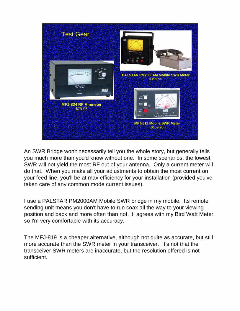
MFJ-834 RF Ammeter$79.95
PALSTAR PM2000AM Mobile SWR Meter$199.95
MFJ-819 Mobile SWR Meter$159.95
An SWR Bridge won't necessarily tell you the whole story, but generally tells you much more than you'd know without one. In some scenarios, the lowest SWR will not yield the most RF out of your antenna. Only a current meter will do that. When you make all your adjustments to obtain the most current on your feed line, you'll be at max efficiency for your installation (provided you've taken care of any common mode current issues).
I use a PALSTAR PM2000AM Mobile SWR bridge in my mobile. Its remote sending unit means you don't have to run coax all the way to your viewing position and back and more often than not, it agrees with my Bird Watt Meter, so I'm very comfortable with its accuracy.
The MFJ-819 is a cheaper alternative, although not quite as accurate, but still more accurate than the SWR meter in your transceiver. It's not that the transceiver SWR meters are inaccurate, but the resolution offered is not sufficient.

Test Gear
Watt's Up Watt Meter Model WU100$59.95
http://www.rc-cars-planes.com/buy-products.html
http://ki0bk.no-ip.com/~pwrgate/LLPG/Site/Welcome.html
Low Loss PWRGate by KIØBK$49.00
Up to 16 vdc and up to 25 amps
Up to 60 vdc and up to 50 amps continuous
KC4YBO
Steve, KC4YBO introduced me to the Watt's Up meter and I found that it gives me a lot of information that I didn't have before. I especially like to use it in conjunction with my Low Loss PWRGate and Smart Charger created by Jim, KIØBK who is local to my own community. The Low Loss PWRGate will allow you to connect a 12 vdc Battery, a 12 vdc Power Supply and has three outputs for radios and accessories. The Low Loss PWRGate will handle up to 25 amps. It will instantly fail over to your connected battery in case of a power failure. During normal, non power failure conditions, it will charge your connected battery and when charging is complete, it will trickle charge and constantly monitor the battery's condition. West Mountain Radio also sells a similar device which will handle up to 40 amps, but they want $140 for it. Check out the Low Loss PWRGate at: http://ki0bk.no-ip.com/~pwrgate/LLPG/Site/Welcome.html

Screwdriver Memory Controller
Ameritron SDC-102 / MFJ-1924 $129.95
I use one of these and I must say it has been a pleasure to use. Programming is as simple as programming your car radio. Just use the 'UP” and “DOWN” buttons to set your SWR and when you're ready, hold down the desired memory button until the readout says, “DONE” and the button is programmed. The next time you want to tune your Gear Motor antenna to that frequency, press that button and the controller moves the antenna to the correct position. There are TEN programmable buttons.
Most of these types of microprocessor controllers are VERY susceptible to stray RF and/or common mode currents, so make sure you choke every wire going into these controllers. Doing so will ensure years of trouble free operation.

Screwdriver Memory ControllerAmeritron SDC-103 $149.95
For Icom Radios
This controller is specifically for ICOM radios. Just hit the tune button on your radio and the controller will be commanded to position your gear motor antenna correctly.

Screwdriver ControllerMFJ-1922B SDC-103 $109.95
For Any Radio
This is a controller for any radio and simply replaces the toggle switch that came with your gear motor antenna with the added benefit of a digital LED readout. If, for instance, you can remember that 1088 will put your antenna on a specific net frequency, then use the up/down buttons to make the readout indicate 1088 and you'll be on target.

Automatic Screwdriver ControllerTennatronix KTT-1, ITT-1, YTT-1 ≈ $300
Available for most Kenwood, Icom and Yaesu Radios
I have not used this device, but the premise sounds interesting. Press the tune button on your radio. Your radio then transmits at 5-10 watts and the TurboTuner-2 adjusts your gear motor antenna while constantly measuring the SWR. Once the lowest SWR is found, your radio returns from tune mode and you're ready for a QSO. The only thing that concerns me with this controller is the lack of fine tune up/down buttons. Invariably, you need to “bump” the antenna one direction of another to obtain the lowest SWR.

Automatic Screwdriver ControllerWest Mountain Radio TARGETuner ≈ $234.95
For Any Radio – It senses RF and adjusts antenna for best SWR
From the West Mountain Radio website:
TARGETuner senses the RF Signal going to the antenna and will work with any Transmitter or Transceiver. It does not depend on a radio data link for band selection and does not need to control the radio for activation.
The motor control uses a bipolar transistor direct switch that incorporates
pulse width modulation for control of motor speed and direction. Stall Current Sensing is programmable and available for some current limit settings.
TARGETuner provides a digital display of Basic Transmitter Frequency and SWR Readout, as well as Manual Tuning Control options which allows the user to monitor antenna performance and manually adjust the antenna if necessary. The TARGETuner System continuously monitors transmitter
frequency and antenna performance and can adjust the antenna accordingly with vehicle movement, antenna icing, or any other proximity or environmental related antenna detuning effects.
The TARGETuner RF Sensing Module is remote from the radio controls. This limits the RF Exposure to other radio and antenna control components. An industry standard shielded CAT-5 Cable serves as an interconnect between the TARGETuner RF Sensor Module and TARGETuner Controller. Power is supplied through industry standard PowerPole Connectors for ease of power connection and fusing.

….....a small, motor drivenRoller Inductor
Micro Switches at the endsof the Roller Inductor, limit travel
A 50Ω match at any frequency
A continuously variable inductor will provide a 50 ohm match for your antenna on any frequency. This roller inductor is from an old WWII ARC-5 transmitter.

Here is my Roller Inductor installed in a short length of 3” diameter PVC pipe with end caps.

There are otherSources; it will justtake some searching

http://cardwellcondenser.com/
Viking Technologies
http://www.servocity.com/index.html
ServoCity Small Gear Motors, Switches and Controllers

Switched inductors can also work well. Shown below is an example although used in
a different application
This is just an example of a variable inductor switch utilizing relays. The typical mobile installation certainly would not need any values above the first four inductors on the left side of this picture.

Software:
Air Core Inductor CalculatorThere are many on-line calculators or you can download this one:
http://lcbsystems.com/Air%20core%20inductor%20v105.exe
www.electronics2000.co.uk/assist/assist.exe
Electronics Assistant:
Also check out AD5X's presentation:“Mobile Ops Hints and Kinks”
http://www.ad5x.com/images/Presentations/AD5XMobileOpsHintsandKinks.pdf

Take a look at the QST article on page 39 of the July 2011 issue. It is a monoband mobile antenna optimized for 75 Meters. The diameter of this main coil is much larger than what you saw in the previous photo. It all equates to efficiency, and efficiency translates into more enjoyable QSOs .
DIY

Jerry also had an article in theMay 2014 issue of QSTwhere he describes how to build a 17 Meter Monobandmobile antenna.
DIY


Ferrite Toroids & Beads:
ResourcesResources
http://www.k0bg.com/http://www.ad5x.com/images/Presentations/AD5XMobileOpsHintsandKinks.pdfhttp://www.w8ji.com/http://www.w8ji.com/verticals_and_baluns.htm
Ferrite Toroids & Beads:http://www.dxengineering.com/http://www.dxengineering.com/Parts.asp?PartNo=DXE-CSB-COMBOhttp://www.fair-rite.com/newfair/index.htmhttp://www.mouser.com/http://www.palomar-engineers.com/1_1_Balun_Kits/1_1_balun_kits.htmlhttp://www.scorpionantennas.com/
Mouser has Mix 31 Toroid Cores available now for $7.00 athttp://www.mouser.com/ProductDetail/Fair-Rite/2631803802/?qs=P8bU7i9nNAWMk1EJQzshLg%3d%3d
The DX-Engineering snap-on beads are the ¾” I.D. ones at:http://www.dxengineering.com/Parts.asp?ID=290&PLID=182&SecID=152&DeptID=42&PartNo=DXE-CSB-750P

SummarySummary
Use the correct size of STRANDED cable to power yourmobile station
Use RG-58 or RG-8X Coax with a STRANDED centerconductor
Proper antenna mounting position and method can't beoverstated
Ground EVERYTHING & Bond EVERYTHING
Use Mix 31 Toroids and Beads to minimize CommonMode Currents
As I answer questions that you may have, I will add the answers to this document. Eventually I will put it on my own web page (with a link from the 3905 CC site) as a living document, so you'll always see the latest info there.

Consultations after this meeting regarding yourparticular installation are welcomed.
My fee is $50/hr with a one hour minimum(waived if you have a Ham license)
The pictures used as examples were not used to disparage anyone. I merely used them to show the good and the bad of installations that are very typical in the Ham Mobile world.
Keep in mind that ALL of the operators that own these mobile stations, routinely enjoy many satisfying QSOs while mobile. I have only wanted to point out how they (and you) could improve their installations and enjoy mobile operating even more. I point this out, not to bash, but to help.
This presentation was based on my own personal experiences with using, testing, modifying, and then retesting various scenarios over the years. I do not claim to be the expert, but I do know what works for me and it can work for you too. 73, Lon, KØWJ