^©mo©^ ^[i^®^? - defense technical information … concerning the tg21 dosimetry protocol are...
TRANSCRIPT

^©mo©^ ^[i^®^?
Performance and dosimetry of Theratron-80 cobalt-60 unit at Armed Forces Radiobiology Research Institute
oo G. H. Zeman M. A. Dooley
DEFENSE NUCLEAR AGENCY
ARMED FORCES RADIOBIOLOGY RESEARCH INSTITUTE BETHESDA, MARYLAND 20814
APPROVED FOR PUBLIC RELEASE; DISTRIBUTION UNLIMITED

REVIEWED AND APPROVED
GARY H. ZEMAN CDB; MSC, Actmg'Chair^fian Radiation Sciences Department
LAWRENCE S. iVt^ERS, Ph. Scientific Director
BOBSY R. ADCOCK ., MSC, USA
Director
Research was conducted according to the principles enunciated in the "Guide for the Care and Use of Laboratory Animals," prepared by the Institute of Laboratory Animal Resources, National Research Council.

UNCLASSIFIED SECURITY CLASSIFICATION OF THIS PAGE (When Data Entered)^
REPORT DOCUMENTATION PAGE READ INSTRUCTIONS BEFORE COMPLETING FORM
I. REPORT NUMBER
AFRRI TR 84-1 2. GOVT ACCESSION NO 3. RECIPIENT'S CATALOG NUMBER
4. TITLE (and Subtllle)
PERFORMANCE AND DOSIMETRY OF THERATRON-80 COBALT-60 UNIT AT ARMED FORCES RADIOBIOLOGY RESEARCH INSTITUTE
5. TYPE OF REPORT S PERIOD COVERED
6. PERFORMING O^G. REPORT NUMBER
7. AUTHORfs) 8. CONTRACT OR GRANT NUMBERfs;
G. H. Zeman and M. A. Dooley
9. PERFORMING ORGANIZATION NAME AND ADDRESS
Armed Forces Radiobiology Research Institute (AFRRI) Defense Nuclear Agency Bethesda, Maryland 20814
10. PROGRAM ELEMENT, PROJECT, TASK AREA a WORK UNIT NUMBERS
NWED QAXM MJ 00112
11. CONTROLLING OFFICE NAME AND ADDRESS
Director Defense Nuclear Agency (DNA) Washington, DC 20305
12. REPORT DATE
March 1984 13. NUMBER OF PAGES
30 14. MONITORING AGENCY NAME & ADDRESSfi/ di/feren( from Controlline Office) 15. SECURITY CLASS, (of this report)
UNCLASSIFIED
15a. DECL ASS! Fl CATION/DOWN GRADING SCHEDULE
16. DISTRIBUTION STATEMENT (of this Report)
Approved for public release; distribution unlimited.
17. DISTRIBUTION STATEMENT (of the abstract entered in Block 20, if different from Report)
18. SUPPLEMENTARY NOTES
19. KEY WORDS (Continue on reverse side if necessary and identify by block number)
20. ABSTRACT (Continue on reverse side If necessary and Identify by block number)
Performance of the AFRRI Theratron-80 cobalt-60 unit is evaluated with regard to accuracy of distance indicators and timer, beam alignment, dose uniformity, efficacy of different collimation techniques, effect of distance and field size on dose rate, and both depth and surface dose-deposition patterns. The ionization chambers and procedures used for cobalt-60 dose measurements and calculations are described in detail. These data and other information provide a baseline for periodic quality-assurance tests and for planning the dosimetric aspects of radiobiology irradiations.
DD 1 JAN 73 1473 EDITION OF 1 NOV 65 IS OBSOLETE UNCLASSIFIED SECURITY CLASSIFICATION OF THIS PAGE (When Data Entered)

CONTENTS
INTRODUCTION 3
METHODS 3
Test Procedures 3
lonization Chambers 3
Radiographic Film 4
Dosimetry Calculations 5
RESULTS 6
Distance Indicators 6
Alignment 6
Bean Uniformity and Penumbra 7
Timer Accuracy 10
Output Versus Field Size 11
Output Versus Distance 12
Roentgen Calibration 13
Dose at Depth 14
Surface Doses 15
DISCUSSION 16
APPENDIX A. COBALT-60 SOURCE CERTIFICATE AND DESCRIPTION 17
APPENDIX B. DOSIMETRY CALCULATION DETAILS 21
ACKNOWLEDGMENTS 28
REFERENCES 28

INTRODUCTION
The Armed Forces Radiobiology Research Institute (AFRRI) Theratron-80 is a cobalt-60 teletherapy unit with a multivane collimator, telescoping penumbra trimmer, and illuminated field indicator and back pointer. The Theratron-80 unit was designed by General Electric, manufactured by Atomic Energy of Canada, Ltd., and first installed at AFRRI in 1978. The unit is licensed by the U. S. Nuclear Regulatory Commission for nonhuman radiobiology research irradiations, electronics irradiations, and instrument cali- brations. Local requirements limit operation to nonrotational modes in either a horizontal plane or vertical plane.
A 3620-curie cobalt-60 source was installed in the AFRRI Theratron-80 unit on 28 June 1983 by Neutron Products, Inc., of Dickerson, MD (see Appendix A). This report includes results of performance tests and dosimetric characterization of the new source.
METHODS
Test Procedures
Performance tests described in this report were adapted from the American National Standards Institute (ANSI).1 Certain ANSI procedures were deleted to meet the needs of a cobalt-60 unit that is not used for rotational irradiation, and other procedures were added to provide basic dosimetry data for future reference.
lonization Chambers
Properties of the three ionization chambers used for dosimetry measurements are given in Table 1. Calibration factors for the Vietoreen chambers are those provided by the manufacturer. The calibration factor for the Exradin chamber is that provided by the National Bureau of Standards in April 1983. The check source readings for the two smaller chambers are those obtained during Theratron-80 measurements using a PTW 0.9-mCi strontium-90 dosimeter check source, serial number 751313. C factors (rad/roentgen) pertain to phantom dosimetry, and are discussed under Dosimetry Calculations.
Ion chambers were operated at ± 350 volts (Vietoreen) or + 100 volts (Exradin). All data represent the average of readings made at opposite polarities. (The magnitudes of all opposite-polarity readings differed by less than 296.) Each chamber was operated with the buildup cap provided by the manufacturer, to provide an equilibrium thickness for cobalt-60 gamma radiation.

Table 1. lonization Chambers
Make Exradin Victoreen Victoreen
Model TE 550-5 550-6
Serial number 197 843 312
Volume (cm3) 0.5 3.3 0.33
Check source 0.135 E-10 amp NA 5.10 R/min
Electrometer Keithley 616 Victoreen 550 Victoreen 550
Calibration factor, Nx 6.94 E9 R/coul 0.996 0.97
C factor (rad/R) 0.939 0.949 0.953
Stem effects were investigated for the two Victoreen ion cham- bers. Each chamber was irradiated at 80.0 cm from the source at the center of a 6 cm X 32 cm field, with the chamber stem alternately parallel and then perpendicular to the long side of the field. These measurements showed that irradiation of the stem increased the ionization current approximately 0.2% for the 0.33-cm3 chamber and 0.1% for the 3.3-cm3 chamber. Conse- quently, stem effects were ignored in subsequent measurements-
Measurements of cobalt-60 dose in the buildup region were done with a Capintec PS-033 0.5-cc thin-window parallel-plate ioniza- tion chamber. This chamber has a very thin entrance window so that true skin dose can be measured. (The window is an aluminized polyester film 3.6 pm or 0.5 mg/cm2 thick.) For all measurements, the parallel-plate chamber was at the entrance surface of a 5-cm- thick polystyrene phantom. The phantom was kept at a constant source-to-surface distance as varying thicknesses of plastic were positioned atop it. Measured ionization currents at different depths were normalized to that at 475 mg/cm2 depth, to construct depth-dose curves.
Radiographic Film
X-ray film used in these tests was Kodak Xomat V Film (for therapy localization) in paper packs. Film was irradiated in a plastic phantom and developed in an automatic processor. Optical densities were measured with a Nuclear Associates, Inc. Model 07-424 digital densitometer, and density scans were done using an Optronics International, Inc. System P-1000 digital image reader operated with 0.4-mm aperture. Film optical density was propor- tional to radiation dose up to density 1.0, and all films were exposed within this linear region.

Dosimetry Calculations
Dosimetry calculations for the Theratron-80 follow the recom- mendations of Task Group 21 (TG21) of the American Association of Physicists in Medicine,2 with the exception that delivered doses are specified in 1CRU muscle3 as the reference material in lieu of water. Details concerning the TG21 dosimetry protocol are given in Appendix B, with results summarized below.
From the reading M of an ion chamber irradiated in air with its buildup cap in place, the exposure X in units of roentgens (R) is calculated as follows:
Exposure X = M • Nx • k^p
where Nx is the cobalt-60 exposure calibration factor for the chamber (listed in Table 1) and k^p is a temperature (T) - pressure (P) normalization factor given by
k _ 273.2 +T(0C) . 760 295.2 P (mm Hg)
The dose D,^ to a small mass of tissue situated in air at the point where the exposure has been measured is given by
Dose in air Dm = M • Nx •. kTp • 0.956 (rad/R)
The factor 0.956 is the product of f = 0.967 (roentgen-to-rad conversion for tissue) and Aeg = 0.989 (correction for attenuation and scatter in the buildup region of the tissue mass) (4).
The dose Dj^ to muscle tissue in situ is calculated from ion chamber measurements at depth in a phantom as follows:
Dose, in phantom Dm = M • Nx • kjp
The factor C has units rad per roentgen, and is evaluated in Appendix B for each chamber in various phantom materials. Note that the C factors are both chamber-specific and phantom- specific, depending on chamber internal dimensions, wall thickness, composition, and phantom composition. Also, a factor commonly known as the displacement or perturbation correction has been included in the C factor. It is shown in Appendix B that, despite the number of variables involved, the C factors listed in Table 1
for cobalt-60 radiation are accurate to within ± 0.5%, whether or not the chamber buildup cap is used within either acrylic, water, or polystyrene phantoms.
RESULTS
Distance Indicators
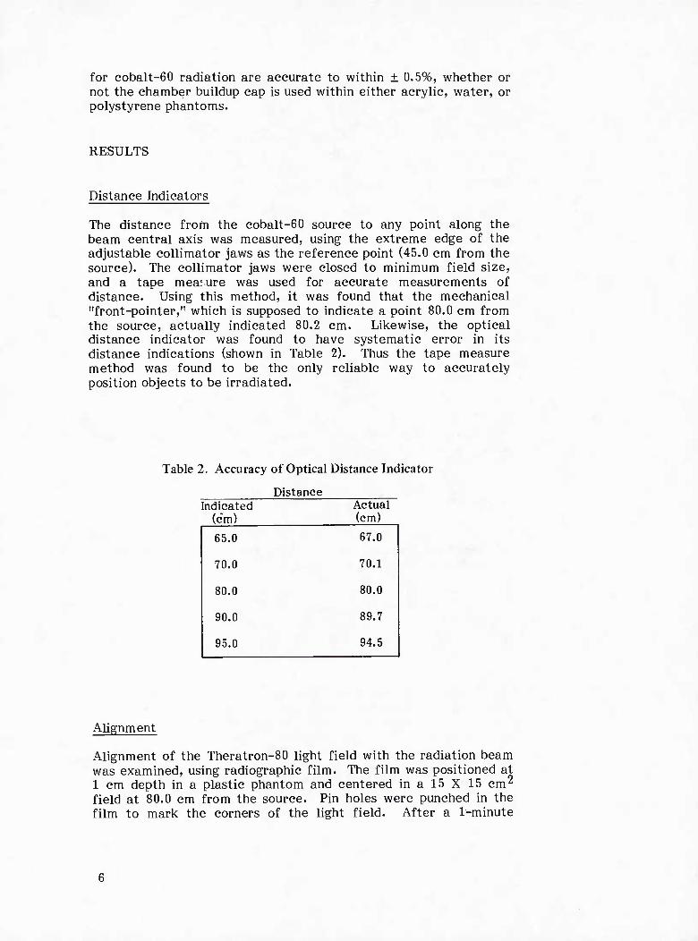
The distance from the cobalt-60 source to any point along the beam central axis was measured, using the extreme edge of the adjustable collimator jaws as the reference point (45.0 cm from the source). The collimator jaws were closed to minimum field size, and a tape measure was used for accurate measurements of distance. Using this method, it was found that the mechanical "front-pointer," which is supposed to indicate a point 80.0 cm from the source, actually indicated 80.2 cm. Likewise, the optical distance indicator was found to have systematic error in its distance indications (shown in Table 2). Thus the tape measure method was found to be the only reliable way to accurately position objects to be irradiated.
Table 2. Accuracy of Optical Distance Indicator
Distance Indicated Actual
(cm) (cm)
65.0 67,0
70.0 70.1
80.0 80.0
90.0 89.7
95.0 94.5
Alignment
Alignment of the Theratron-80 light field with the radiation beam was examined, using radiographic film. The film was positioned at 1 cm depth in a plastic phantom and centered in a 15 X 15 cm2
field at 80.0 cm from the source. Pin holes were punched in the film to mark the corners of the light field. After a 1-minute

exposure, the developed film (Figure 1) showed good congruence between the light and radiation field.
Figure 1. Radiograph of a 15 X 15 cm2 cobalt-60 beam. Film was exposed at 1 cm depth in a plastic phantom, 80.0 cm from the source.
Alignment of the light field cross hairs was examined by marking on a paper the location of the cross-hair intersection as the collimator was rotated. The points so marked cescribed a circle with a diameter of 2,5 mm. During this rotation the edges of a square light field fell on exactly (± 0.5 mm) the same locations when the collimator was stopped at 90° increments. It was concluded that the collimator jaws were properly aligned and that the cross hairs mark a point 1.25 mm removed from the radiation beam centerline.
Beam Uniformity and Penumbra
Uniformity of the radiation beam was studied by scanning the optical density of the film shown in Figure 1 in both lateral and longitudinal directions. One such scan is shown in Figure 2". The nominal field size (15 cm) can be seen to correspond to approxi- mately the 50% intensity level; this occurs at the boundary of the light field. While the central region of the beam is symmetrical

100
75
< o P 50
25
■ M ' « «-,
FWHM = 15.4 cm
PENUMBRA WIDTH = 3.2 cm
0 l.«-*i I J I I L J I i I i VJ I 10
LONGITUDINAL DISTANCE (cm)
15 20
Figure 2. Optical density scan across a 15 X 15 cm2 cobalt-60 radiograph. The film is that shown in Figure 2.
and uniform, the edges of the beam show a characteristic pen- umbra region. The width of the penumbra is determined by the diameter of the cobalt-60 source and the distance to the end of the collimator. For irradiations at 80 cm distance, the scan in Figure 2 shows that the nominal field size should be 3 cm larger than the region to be irradiated, to attain 95% dose uniformity across the region.
The width of the penumbra region can be controlled if needed for more precise irradiation localizations. This is accomplished by using either the collimator trimmer-bars or by adding lead brick shields near or on the surface of the irradiated object. Figures 3 and 4 show optical density scans and films irradiated with different collimation techniques. Both the trimmer and the lead block techniques provide a sharper edge to the radiation field than obtained with the normal collimator, with the lead blocks being more efficient than the trimmers. The disadvantage of trimmer- bars and lead blocks is that their attenuation is not as complete as that of the normal collimator, so a somewhat higher dose is deposited beyond the edge of the normal penumbra region.

Figure 3. Radiographs of 5 X 10 cm2 cobalt-60 beams. Films were located at 5 cm depth in a plastic phantom; the phantom surface was 80.0 cm from the cobalt-60 source. Collimaton techniques were (A) normal collimator, (B) trimmer-bars extended, and (C) L-inch lead blocks at phantom surface.
\ * !—= I" LEAD SLOCKS AT i {I PHAMDM SURFACE
B
DISTANCE (cm)
NORMAL -\ i ! rni i iHAinfi^ \*
«I" LEAD BLOCKSAT PHANTOM SURFACE
COLLIMATOR TRIMMERS
N.
DISTANCE Icm)
Figure 4. Penumbra optical density scans for different collimation techniques. Films were exposed as in
Figure 3 at depths of (A) 1 cm and (B) 10 cm.

Timer Accuracy
Timer accuracy was evaluated by measuring beam-on time with a stopwatch and by comparing radiation output for different expo- sure times. Stopwatch measurements were based on timing the green beam-off light on the Theratron-80 control console. These measurements indicated that actual beam-on times were 0.8 ± 0.2 seconds shorter than indicated on the Theratron-80 timer. The timed radiation output measurements shown in Figure 5 confirmed the stopwatch data; least squares analysis gave a timer error of 0.97 ± 0.10 seconds. Further confirmation of the measured value of timer error came from observations of measured dose rate versus timed output measurements.
120 -
100
80
S 60 t- <
40
20
:TIMER ERROR = 0.97 ±0.10 seconds
J I I I I 20 40
t (seconds)
60
Figure 5. Timed output measurements to measure timer error
10

Timer error is due to source motion between the on and the off positions. For maximum precision, irradiation times calculated from measured dose rates should be increased by 0.97 seconds to account for this motion.
Output Versus Field Size
The adjustable Theratron-80 collimator can be used to form rectangular fields from 5 to 33 cm wide as measured at 80.0 cm from the cobalt-60 source. The maximum and minimum field sizes at any distance from the source are shown in Figure 6.
50
\
vs. vs.
100
\
\\ \\ \\ A i V 200 \ \\
I S V xMAXIMUM I \\^^ FIELD WIDTH
1^=MINIMUM \ \ 300 — \ FIELD WIDTH \ X
A l 96% UNIFORM^ \ \ \ FIELD WIDTH \ \
400
il i i i i i \ i X i 25 50 75 100 125
FIELD WIDTH (cm) 150 175 200
Figure 6. Field sizes available at different distances from cobalt-60 source
Radiation output was measured at 80.0 cm distance for the range of square field sizes, allowed by the adjustable collimator. Figure 7 shows the measured radiation outputs relative to that for a 10 X 10 cm^ field. The increased output at larger field sizes is generally attributed to forward scattered radiation from the colli- mator faces. Note that at distances other than 80.0 cm, the shape of the curve shown in Figure 7 may be somewhat different.
11

-•* — 1.06
- /
^"^
1.04 - / /
E - / u /
o / « 1.02 _ / © / \- / p / a. /• f- / Z3 / o / LU / p 1.00 - • / < / _i / LU / ac
/ • 0.98
-
/ •
/
/ 0.96 •
/ 1 1 1 1 1 1 1
10 20 SQUARE FIELD SIZE (cm)
30
Figure 7. Relative radiation output versus square field width at 80.0 cm from cobalt-60 source
Output Versus Distance
Radiation output was measured at various distances from the cobalt-60 source from 48.5 cm (end of collimator frame) to 400 cm. For these measurements, maximum field size was used, and the beam was directed either vertically down through the unit's isocenter, or horizontally at 1.5 meter above the floor. With the beam directed horizontally, the measured radiation output at 80.0 cm was the same (within 0.5%) as with the beam directed verti- cally. At all distances, the radiation output was fairly accurately predicted (within 2%) from that at 80.0 cm by the inverse square law. Figure 8 shows the degree of departure from inverse square behavior observed in" these measurements. Scattered radiation from the collimator is the presumed cause of the increased output measured at reduced distances from the source.
12

1.02 r-
< UJ
S
48.5 60 80 100 400 DISTANCE (cm)
Figure 8. Departure of measured radiation output from inverse square behavior. Each point is the ratio of measured output to that predicted from the output at 80.0 cm using the inverse square law. Data apply only to maximum field size. Spread in individual points indicates the precision of replicate measure- ments.
Roentgen Calibration
Radiation output was calibrated using the three ionization cham- bers described in Methods. The readings of each chamber were corrected by its calibration factor and normalized to 220C and 760 mm Hg. Results of these measurements are given in Table 3. The results in Table 3 agree within the ± 296-3% uncertainty associated with the individual calibration factors of the chambers.
Table 3. Exposure Rate Measurements
Chamber Roentgens Per Minute*
Exradin TE-197 110.5
Victoreen 550-5 108.0
Victoreen 550-6
Average
110.1
109.5
*At 80.0 cm in 10 X 10 cm2 field on 20 July 1983
13

The radiation output at other distances or for other field sizes can be calculated using data presented in earlier sections of this report. For example, the RHM output in roentgens per hour at 100 cm distance for maximum field size is
RHM = 109.5 R/min • 60 min/hr • (80 cm/100 cm)2
• 1.063 • 0.999 = 4465 R/hr © 1 meter
where the field size factor 1.063 is from Figure 7 and the inverse- square departure factor 0.999 is from Figure 8. The measured 4465 RHM agrees within 2.6% with the nominal value of 4400 RHM, effective 24 June 1983, obtained from Neutron Products, Inc.
Dose at Depth
Tissue-air ratios (TAR's) and percentage depth-dose data for rec- tangular cobalt-60 beams are available in the literature (e.g., reference 4). To establish the applicability of published data, depth-dose profiles for three field sizes were measured in a water phantom. The results in Table 4 show agreement within 1.4% between measured and published TAR's. Thus published TAR's and percentage depth-dose data for cobalt-60 beams can be applied with reasonable reliability to this Theratron-80 unit. Note, how- ever, that in many cases in radiobiology irradiations, the geomet- rical conditions differ widely from those applicable to the pub- lished data, particularly for whole-animal irradiations or highly contoured surfaces. In these cases, individual determination of TAR or depth-dose profiles is necessary.
Depth
Table 4. Tissue-Air Ratios
6X6cm2 10X10 cm2 20 X 20 cm2
5 cm:
Measured 0.865 0.906 0.953
Ref. 4 0.862 0.905 0.957
10 cm:
Measured 0.661 0.719 0.793
Ref. 4 0.655 0.709 0.790
15 cm:
Measured 0.484 0.541 0.629
Ref. 4 0.485 0.540 0.633
14

Surface Doses
Cobalt-60 dose measurements in the buildup region (0-5 mm depth) showed the expected "skin-sparing" effect at 80 and 100 cm from the source; namely, entrance doses were one third to one half of the dose at 5 mm depth. For irradiations at shorter distances, the skin-sparing effect was actually reversed, with as high as 25% excess dose being delivered at 1 mm depth in the worst case. This phenomenon depended on field size, and was presumably due to low-energy secondary electrons arising in the beam collimators. Similar data have been reported by others^ for Theratron-80 and other teletherapy units. Despite the markedly different shapes of the shallow portions of the depth-dose curves in Figure 9, all curves coincided (± 0.5%) at the 7-mm and 11-mm depths.
o Q
20 x 20 cm2 (MAX FIELD) @ 48.5 cm
10 x 10 cm1^ 48.5 cm
20 x 20 en/ (a 80 cm
..„„.„......... 10 x 10 cm2 (a 80 or 100 cm
J_ _L 0.2 0.4 0.6 0.8
DEPTH (cm) IN UNIT DENSITY MATERIAL
1.0 1.2
Figure 9. Cobalt-60 dose in the buildup region. Doses measured with a 0.5-mg/cm2 window parallel-plate ion chamber were normalized to the dose at 0.475 cm depth for each field size and distance.
15

DISCUSSION
Test results included in this report document satisfactory perfor- mance of the Theratron-80 cobalt-60 Teletherapy unit at AFRRI. The data are intended to serve as a baseline reference for periodic quality assurance tests and for planning the dosimetric aspects of radiobiology irradiations. Dosimetry procedures described herein reflect the implementation of recent recommendations of Task Group 21 of the American Association of Physicists in Medicine.2 The AAPM protocol has been adopted entirely, with the exception of AFRRI tissue doses being specified in 1CRU muscle,3 as is the practice in neutron-gamma dosimetry,^ rather than in water. (Muscle doses are 1% lower than water doses for cobalt-6'0.)
Sample radiographs and optical density scans included in this report illustrate the degree of dose uniformity achievable for radiobiology irradiations. Selection of collimation techniques was shown to be a critical aspect of partial-body irradiations, particularly for cobalt- 60 beams, which have a relatively large penumbra region. Factors that must be considered are (a) the depth and degree of dose uniformity required in the irradiated volume, and (b) the amount of dose reduction needed for structures at different distances from the irradiated volume. Radiographic film densitometry remains a rapid and informative technique for evaluating and documenting the dose uniformity for specific applications.
The surface dose measurements reported here emphasize the need for considering buildup material in radiobiologic irradiations. For dosimetry measurements, the detector (TLD or ion chamber) is conventionally surrounded with 4-5 mm of unit density material to ensure measurement of the equilibrium or "d-max" dose. This same practice must be followed in specimen irradiations to avoid the highly variable dose deposition that can occur at depths up to 3 mm. For irradiations of experimental animals, the nature of the depth-dose curve in the buildup region will depend on both field size and irradiation distance. Special measurements of this effect may be necessary in cases where the dose to skin or shallow lying organs (0-3 mm) is critical to experimental outcome.
16

APPENDIX A.
COBALT-60 SOURCE CERTIFICATE AND DESCRIPTION
17

TELETHERAPY SOURCE TRANSFER
This is to certify that a cobalt-60 source:
Model Number: NPI-20-4000W Serial Number: T-627 Containing 3520 curies as of 6/24/83
and which has been determined by helium pressure test and by wipe test to be leak free, has been installed in a teletherapy unit described as follows:
Manufacturer: AECL Model Number: Theratron 80 Serial Number: 86
This source is hereby transferred from Neutron Products' Radioactive Materials License MD-31-025-03 to Armed Forces Radiobiology Research Institute's License 19-08330-03.
This will also certify that a cobalt-60 source described as follows:
Model Number: C146 Serial Number: S1846 Containing 1983 curies as of 4/1/83
has been determined by a wipe test to be leak free and has been removed from the above teletherapy unit and transferred from
Armed Forces Radiobiology Research Institute's License 19-08330-03 to Neutron Products' License MD-31-025-03.
We have witnessed the inspection and operation of the above tele- therapy unit after completion of the installation by Neutron Products, Inc. and have found the unit to be operating properly and safely.
C Neutron Products, Inc.
Date C' ^%-% ^2 Date ^ - Zfi - % 2>
neuTRon PRODUCTS mc
19

COBALT-60 SOURCES FOR RADIATION THERAPY
Holder Screw Cap
S fi
Source Hold Down Spring
Screw Cap Lock Washer
Outer Capsule End Cap
inner Capsule End Cap ("X
Tungsten Shleld^^^X MJ
^^^COBALT CASTING
Inner Capsule
Outer Capsule
International Source Holder
SOLID SLUG OF COBALT-60 assures fixed distribution of radiation in the beam; the apparent half-life will not change with prolonged use of the source.
DOUBLE ENCAPSULATION, with or without internal heavy metal shield, is fabricated, seal-welded, leak-tested, and checked for external contamination to highest standards.
Source capsule holder is provided for any teletherapy machine, including INTERNATIONAL CAPSULE (as shown), SHIELDED DRAWER, or other holder as appropriate.
NEUTRON PRODUCTS sources and fabrication procedures have been approved for standard applications in beam therapy units. Licensed personnel provide installation and radiation surveys.
Prices quoted on request will cover FULL SERVICE --- shipping, rigging, installation, routine maintenance, removal and disposal of turn-in source. Special maintenance, calibration, leakage field surveys, reports to regulatory agency, and other services may be ordered.
For further information please write or call:
neuTRon PRODUCTS mc
20

APPENDIX B.
DOSIMETRY CALCULATION DETAILS
21

The dosimetry protocol of Task Group 21 of the American Association of Physicists in Medicine involves an analysis of the construction and response characteristics of each ion chamber. Calculations indicated by the protocol are detailed below for three ion chambers used in Theratron-80 dosimetry measurements.
Ngas is a chamber-specific parameter defined as the dose to ion chamber gas per unit electrometer reading M. For an ion chamber with matching wall and buildup cap material, Ngas is calculated as follows:
N 'gas = Nx K(W/e) Aion Awall 6wall
wall /T , ■. wan / -. air (L/p) air (yen/p)wall
where N.
K
(W/e)
^ion
Cobalt-60 exposure calibration factor for the chamber, in units of roentgen per unit electrometer reading M
2.58 X lO"4 coul/kg - R
33.7 joule/coul
1.00, ion collection efficiency of the chamber at time of calibration
^wall = Correction for attenuation and scatter in chamber wall and buildup cap (see below)
wall
(L/P &
"WPCS,
1.005, ratio of absorbed dose to collision fraction of kerma for ion chamber wall material
1.145 (A-150 plastic) or 1.103 (acrylic), ratio of mean restricted collision mass-stopping power of chamber wall material to that of air
0.906 (A-150 plastic) or 0.925 (acrylic), ratio of the mean mass energy absorption coefficient for air to that of chamber wall material
23

The factor Awa^ defined above is a chamber-specific correction, dependent on internal dimensions and wall thickness of the ion chamber. Table 5 lists critical dimensions of the three ion chambers of concern as well as derived2 values of Awau . Combining terms in the above equation gives Ngas/Nx values as listed in Table 5.
Table 5. Physical and Dosimetric Parameters of lonization Chambers for Cobalt-60 Radiation
Exradin TE Victoreen 550-5 Victoreen 550-6
Volume (cm3) 0.5 3.3 0.33
Inner diameter (cm) 0.90 1.27 0.48
Inner height (cm) 0.85 2.66 2.79
Wall/cap material A-150 Acrylic Acrylic
Wall thickness (g/cm2) 0.1 0.166 0.133
Wall + cap thickness (g/cm2) 0.59 0.534 0.549
Awall 0.985 0.997 0.992
Prepl 0.988 0.983 0.994
Ngas/Nx (rad/R) 0.830 0.854 0.850
a (no buildup cap) 0,70 0.83 0.78
a (with buildup cap) 1.0 1.0 1.0
(L/P) -n 1.145 1.103 1.103
^ wal Acrylic 0.9809 1.00 1.00
Water 1.0109 1.0306 1.0306
Polystyrene 0.9754 0.9944 0.9944
(L/p) -f
Acrylic 1.103 1.103 1.103
Water 1.133 1.133 1.133
Polystyrene 1.112 1.112 1.112
24

The dose Bme(^ deposited to a medium or phantom is calculated as follows from ion chamber readings within the medium:
^ ™ xr VT \ /-r i \ wall / , \ med Dmed = M • KTp • Ngas ja(L/p) air. (y en/P ) wall
+
(1-a) (L/p ) ^ j PionPrepl
where a = Fraction of total ionization produced by electrons arising in the chamber wall; a is dependent on the chamber wall thickness
/, \wall [ - J = Ratio of the mean restricted collision mass- \ p / air stopping power of the chamber wall to that
of air (1.145 for A-150 plastic or 1.103 for acrylic)
med (y /p) = Ratio of the mean mass energy absorption
wall coefficient of the phantom medium to that of the chamber wall material
(1-a) = Fraction of total ionization produced by electrons arising in the phantom
. med = Ratio of the mean restricted collision mass-
air stopping power of phantom medium to that of air
pion = i-00 (Exradin and Victoreen chambers), correction factor for ion recombinations
Prepl = Replacement factor, which is dependent on the chamber diameter and corrects for replacement of a volume of phantom material by ion chamber air
25

From Dme(3, the TG21 protocol calculates the dose to water as a reference. The dose to water, Dwater' is calculated as follows:
^water - Dmed en
water
ESC medium
where
{¥) water
medium
the ratio of the mean mass energy absorption coefficient of water to that of the phantom material
(—)
u N water en
'acrylic 1.031
en water
= 1.036 polystyrene
ESC = excess scatter factor due to the different electron compositions in water and the phantom material
ESC = 1.00 for polystyrene, but will be less than 1.00 for acrylic phantoms. The actual value depends on the depth of measurement and the field size at depth. Table 6 lists ESC factors for acrylic phantoms at two depths and three field sizes.
26

Table 6. Excess Scatter Factor* From an Acrylic Phantom
Field size
Depth (cm) 5 cm x 5 cm 10 cm x 10 cm 20 cm x 20 cm 30 cm x 30 cm
0.5 .997 .996 .995 .996
5.0 .986 .987 .989 .991
♦Because the ESC varies with field size and depth in the acrylic phantom, it is recommended that only phantoms constructed of water, polystyrene, or A-150 plastic be used for cobalt-60 dosimetry.
Dosimetry at AFRRI, however, is referenced to the dose in ICRU muscle. Dmuseie is calculated by
n ■ n /^V L'muscle - L'water ^ p I
muscle
water
/yenxmuscle
where I——) = .992, the ratio of the mean mass energy \ p ^water
absorption coefficient of water to ICRU muscle (4).
To simplify the dose calculations, Dmugde can be expressed as follows:
Dmuscle - M • kTp • N • C
where C is a factor with units rad (muscle)/roentgen to be used with a specific chamber in a specific phantom.
Values of C calculated from the TG 21 protocol are shown in Table 7. These values show that for cobalt-60 radiation, single C values can be applied to each chamber, with or without its buildup cap, when used in various phantom materials, with an accuracy loss of no more than ± 0.5%.
27

Table 7. C Factors* for Phantom Dosimetry
Buildup Cap Phantom Exradin TE Victoreen 550-5 Victoreen 550-6
Yes Any t" 0.941
No Acrylic' 0.937
No Water 0.936
No Polystyrene 0.940
0.946 0.952
0.947 0.953
0.946 0.952
0.949 0.955
*Rad(muscle)/roentgen
tNote that these values do not include the ESC factor and that this factor must be applied when using an acrylic phantom. For example, C = .941 • ESC rad(muscle)/roentgen when the Exradin TE chamber with buildup cap is used in an acrylic phantom.
ACKNOWLEDGMENTS
The authors thank J. Ritz for assistance in Theratron-80 operation and data collection and J. Black for performing the X-ray film density scans.
REFERENCES
1. Procedures for periodic inspection of cobalt-60 and cesium-137 teletherapy equipment. Report No. ANSI 449.1-1978. American National Standards Institute, New York, 1978.
2. Task Group 21 of AAPM. A Protocol for the Determination of Absorbed Dose from High Energy Photon and Electron Beams. Medical Physics 10(6): 741-771, 1983.
3. Neutron dosimetry for biology and medicine. Report No. 26. International Commission on Radiation Units and Measure- ments, Washington, DC, 15 January 1977.
4. Johns, H. E., and Cunningham, J. R. Physics of Radiology. Charles C. Thomas, Springfield, Illinois, 1983.
28

5. Leung, P. M. K., and Johns, H. E. Use of electron filters to improve the buildup characteristics of large fields from cobalt- 60 beams. Medical Physics 4: 441-444, 1977.
6. Broerse, J. J., Mijnheer, B. J., and Williams, J. R. European protocol for neutron dosimetry for external beam therapy. British Journal of Radiology 54: 882-898, 1981.
29