mo dular se nsor systems for real time pro cess control ... · in cooperation with festo and bosch...
TRANSCRIPT
Page 1
Joint Project MoSeS-Pro
Modular Sensor Systems for real time Process Control and Smart Condition Monitoring
http://www.moses-pro.de
Source: Oliver Dietze

Page 2
� Funded within the research focus area ‚Sensor-based electronic systems for applications for Industrie 4.0 – Selekt I4.0‘
� Funding period: 10/2015 – 9/2018 � Project budget 3.1 Mio. €, 73 % funded by German Federal Ministry of
Education and Research (BMBF)� Project management VDI/VDE Innovation + Technik, Berlin, Germany
Project partners� Bosch Rexroth AG, Facility Homburg (associated)
� Festo AG & Co. KG, Facility St. Ingbert (associated)
� CANWAY Technology GmbH, Ostbevern
� ESR Pollmeier GmbH, Ober-Ramstadt
� Lenord, Bauer & Co. GmbH, Oberhausen
� Sensitec GmbH, Lahnau
� Fraunhofer IMS, Duisburg
� TU Kaiserslautern, ISE, Kaiserslautern
� ZeMA gGmbH, Saarbrücken (coordinator)
Basic informations and consortium

Page 3
Contents and goals at a glance
� Modular and open sensor system kit for assembly, handling and packaging processes in Industrie 4.0
� In addition to optimized sensing functions: Extending of signal processing capabilities for intelligent condition monitoring
� Sensor principles – Primarily magnetoresistive (XMR) technologies with focus on TMR� wide range of applications (current, angle, length and position measurement)
– Integration of further sensing principles� Vibration/acoustics, VIS/IR cameras, pressure, oil quality
– Self-sensing drives: Servo control and condition monitoring� based on voltage & current signals with online model-based analysis
� Real time wireless communication & energy harvesting for flexible integration
� Laboratory tests of MoSeS kit based on different application scenarios
� Demonstration of sensor system kit embedded in industrial processes� in cooperation with Festo and Bosch Rexroth (associated partners)

Page 4
Application scenario I
� Electromechanical axes for assembly and handling systems– Extending available sensor technologies for improved
functionality and smart condition monitoring by sensor fusion (e.g. current, angle, andvibration measurements)
– Both for End-of-Line testing & quality assurance and for condition monitoring in customer applications
– Establishingstandardizedformats for data exchange
Source: Festo
Page 5
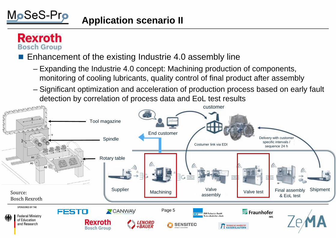
Application scenario II
� Enhancement of the existing Industrie 4.0 assembly line– Expanding the Industrie 4.0 concept: Machining production of components,
monitoring of cooling lubricants, quality control of final product after assembly– Significant optimization and acceleration of production process based on early fault
detection by correlation of process data and EoL test results
Source:
Bosch Rexroth
customer
Supplier Machining Valve assembly
Valve test Final assembly & EoL test
Shipment
Costumer link via EDI
Delivery with customer specific intervals /
sequence 24 h
Tool magazine
Spindle
Rotary table
End customer

Page 6
Application scenario III
� Sensors and compact positioning drives with integrated sensors– e.g. format adjustment actuators
for packaging machines: trend towards higher flexibility only possible with extended functionality
– primarily partially redundant angle & current measurements� provides basis for
condition monitoring– Also woodworking and
textile machinery as further applications
Source:
Lenord+Bauer

Page 7
Application scenario IV
�
� Efficient and compact drive systems – Servo, torque or linear motors, electronics & control with customer-specific
configuration for handling systems in production and R&D – Complex and high
performance test bench developed in DFG project (ZeMA)� Testing of optimized
position and currentmeasurement andespecially self-sensingdrive systems
� Combination forcondition monitoring
Source: ZeMA, group drive technology
Signal electronics
Half-bridge driver
Curr. sensor
Power electronics Position
sensor
Test object

Page 8
Application scenario V
� Electronic modules based on DSP/FPGA for MoSeS kit – Realization of functional models and demonstrators within the project� important part of electronic systems and interface to process control
– Later: Improvement of customized measurement hardware, e.g., hardware-in-the-loop (HIL) test benches for automotive production or vibration analysis / condition monitoring
� Improved sensor modules based on XMR with integrated electronics – Industrial applications, but also automotive / consumer applications– Self-X functionality (self diagnosis, configuration, and adaptation) � Helps to better fulfil customer requirements regarding functionality and
robustness
Page 9
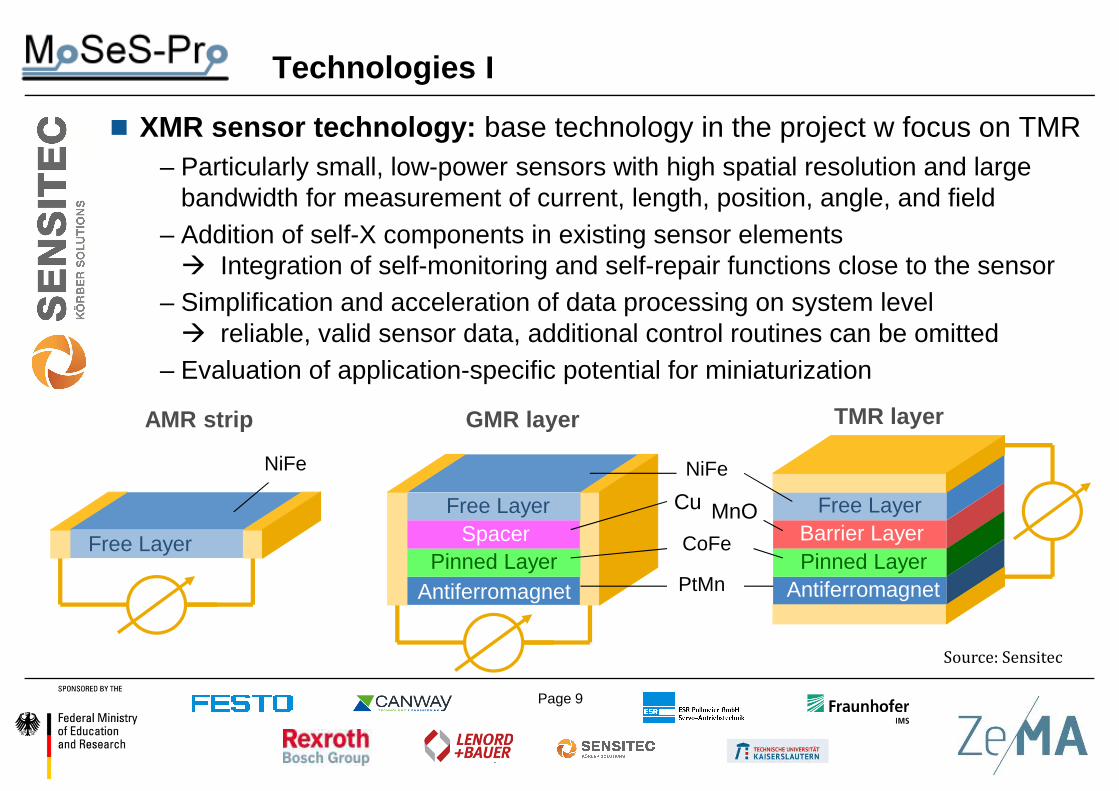
Technologies I
� XMR sensor technology: base technology in the project w focus on TMR– Particularly small, low-power sensors with high spatial resolution and large
bandwidth for measurement of current, length, position, angle, and field– Addition of self-X components in existing sensor elements� Integration of self-monitoring and self-repair functions close to the sensor
– Simplification and acceleration of data processing on system level � reliable, valid sensor data, additional control routines can be omitted
– Evaluation of application-specific potential for miniaturization
AMR strip GMR layer TMR layer
Pinned Layer
SpacerFree Layer
NiFe
Pinned LayerAntiferromagnet
Free Layer Cu
CoFe
NiFe
PtMn
MnOBarrier LayerPinned Layer
Antiferromagnet
Free Layer
Source: Sensitec
Page 10
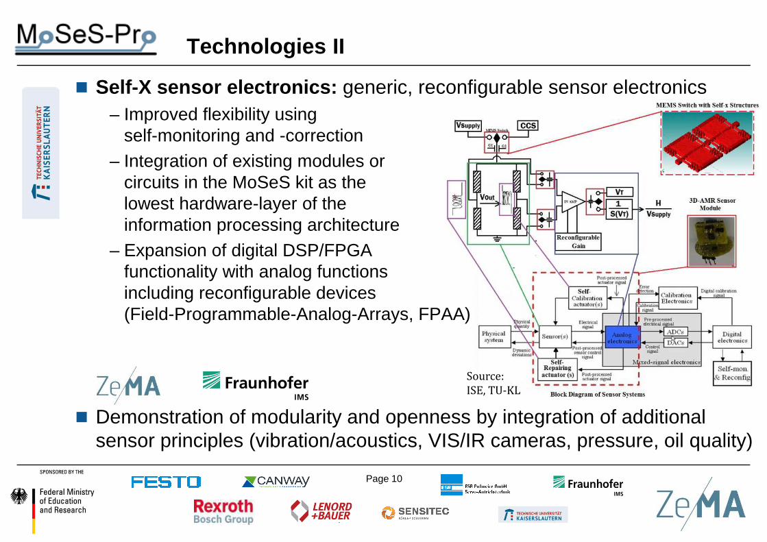
Technologies II
� Self-X sensor electronics: generic, reconfigurable sensor electronics– Improved flexibility using
self-monitoring and -correction– Integration of existing modules or
circuits in the MoSeS kit as the lowest hardware-layer of the information processing architecture
– Expansion of digital DSP/FPGA functionality with analog functionsincluding reconfigurable devices (Field-Programmable-Analog-Arrays, FPAA)
� Demonstration of modularity and openness by integration of additional sensor principles (vibration/acoustics, VIS/IR cameras, pressure, oil quality)
Source:
ISE, TU-KL
Page 11
Technologies III
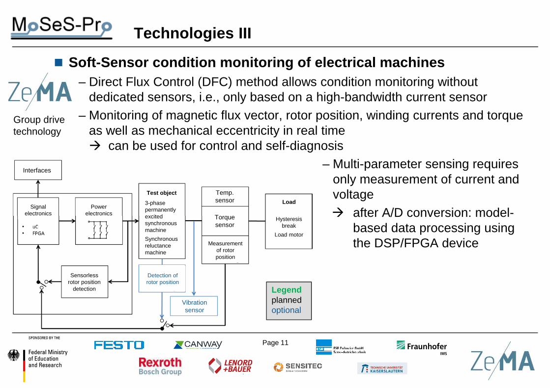
� Soft-Sensor condition monitoring of electrical machines – Direct Flux Control (DFC) method allows condition monitoring without
dedicated sensors, i.e., only based on a high-bandwidth current sensor – Monitoring of magnetic flux vector, rotor position, winding currents and torque
as well as mechanical eccentricity in real time� can be used for control and self-diagnosis
– Multi-parameter sensing requires only measurement of current and voltage � after A/D conversion: model-
based data processing using the DSP/FPGA device
Group drive technology
Interfaces
Signalelectronics
Sensorlessrotor position
detection
Powerelectronics
Test object
3-phase permanently excited synchronous machine
Synchronous reluctance machine
Temp. sensor
Torque sensor
Measurement of rotor position
Load
Hysteresis break
Load motor
Detection of rotor position
Vibration sensor
Legendplanned optional

Page 12
Technologies IV
� Condition monitoring using statistical data analysis– Promising results in previous study using sensor fusion and signal processing
techniques for hydraulic systems – Method based on existing process sensor data (pressure, temperature, flow,
motor power, valve position, …)– Compensation of defective
sensors without degrading condition monitoring capability� improved robustness and
customer acceptance– In this project extension
towards sensor elements with higher bandwidth� Signal pre-processing
integrated in sensor modules required
Group measurement technology
Feature extraction Feature selectionDimensionality reduction
& classification
Statistical Moments (time/freq. domain)
LDA + kNN / SVM / PLSR
(patternrecognition)

Page 13
Technologies V
� Wireless communication / energy harvesting technologies– Improved flexibility required� Wireless real time data transmission in addition to wire-based signal
transmission (IO-Link wireless planned)� Realization of a self-sufficient power supply
– Safe and secure datatransmission
– Reference: Self-sustainingwireless sensor (Monitoring ofcooling media in steel plant)
(Que
lle: F
raun
hofe
rIM
S)
(Que
lle: I
O-L
ink
Sys
tem
besc
hrei
bung
)
So
urc
e:
Fra
un
ho
fer
IMS
So
urc
e:
IO-L
ink
, sy
ste
m d
esc
rip
tio
n

Page 14
Technologies VI
� DSP/FPGA-based electronic modules– Powerful signal acquisition, preprocessing and feature extraction close to
sensor, especially for periodic signals� Connection between sensor und process layer
– Highly modular: variable signals, sampling rates and interfaces– Subsequent transfer of electronic demonstrators into series production
Source:
Canway Technology
Control

Page 15
� Self-X sensor electronics: Realization along process chain
� Self-sensing drive systems: Core partners
� Condition Monitoring: Realization along process chain
Project consortium: Interfaces and topical clusters
Group drive technology+ X?
Group measurement technology
Page 16
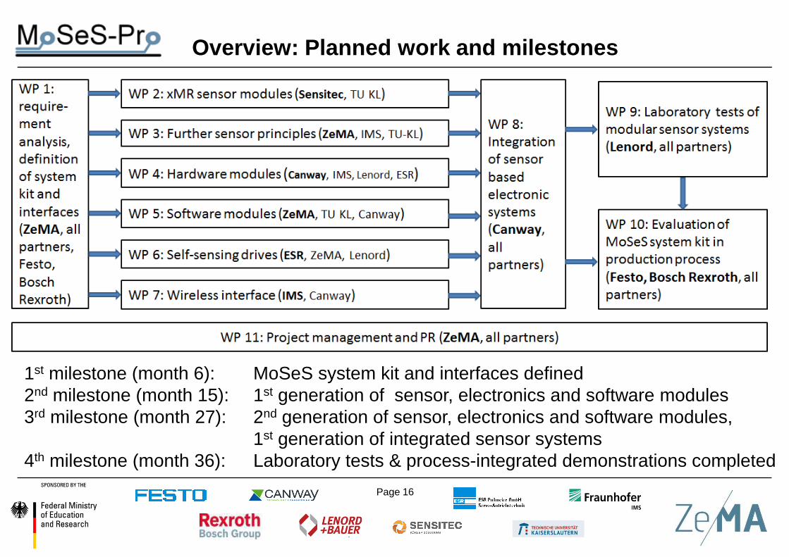
Overview: Planned work and milestones
1st milestone (month 6): MoSeS system kit and interfaces defined2nd milestone (month 15): 1st generation of sensor, electronics and software modules3rd milestone (month 27): 2nd generation of sensor, electronics and software modules,
1st generation of integrated sensor systems4th milestone (month 36): Laboratory tests & process-integrated demonstrations completed

Page 17
Methodology: Definition of application-specific data acquisition chains
Measured quantity Sensor data
drive
load
Spindel
Umgebung
Example: Application Festo
� Test bench specific sensors (light gray)
� Planned sensors (blue)
� Optional sensors (dark gray)

Page 18
Example: Application Festo
Methodology: Measured quantities & sampling rates
temperatures(3-5x)
IR emission(2-3x)
vibration (7x)magnetic field (1x)
ultrasonic (1x)motor current (3x)
encoder signals (2x)(linear/rotatory)
~1 Hz ~ 100 Hz ~ 50 kHz ~ 500 kHz ~ x MHz fs
< 500 S/s <100 kS/s < 5 MS/s
sens
or d
ata
raw
vol
ume
Sampling rates

Page 19
Project MoSeS-ProModular Sensor Systems for real time Process Control and Smart Condition Monitoring
Coordination:
Prof. Dr. Andreas Schütze,ZeMA, group measurement technology
Contact: [email protected]
http://www.moses-pro.de