mmt manuals
TRANSCRIPT

Mammotome® Biopsy SystemService Manual
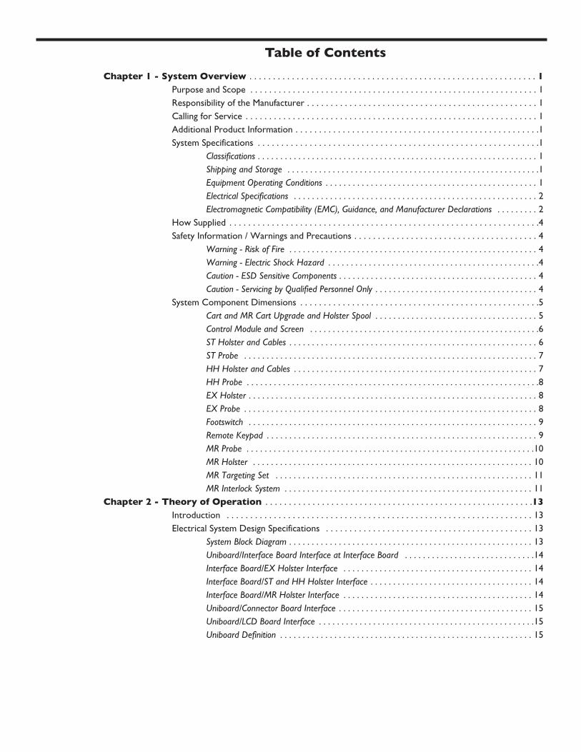
Chapter 1 - System Overview . . . . . . . . . . . . . . . . . . . . . . . . . . . . . . . . . . . . . . . . . . . . . . . . . . . . . . . . . . . . . 1Purpose and Scope . . . . . . . . . . . . . . . . . . . . . . . . . . . . . . . . . . . . . . . . . . . . . . . . . . . . . . . . . . . . . 1Responsibility of the Manufacturer . . . . . . . . . . . . . . . . . . . . . . . . . . . . . . . . . . . . . . . . . . . . . . . . . 1Calling for Service . . . . . . . . . . . . . . . . . . . . . . . . . . . . . . . . . . . . . . . . . . . . . . . . . . . . . . . . . . . . . . 1Additional Product Information . . . . . . . . . . . . . . . . . . . . . . . . . . . . . . . . . . . . . . . . . . . . . . . . . . . .1System Specifications . . . . . . . . . . . . . . . . . . . . . . . . . . . . . . . . . . . . . . . . . . . . . . . . . . . . . . . . . . . .1
Classifications . . . . . . . . . . . . . . . . . . . . . . . . . . . . . . . . . . . . . . . . . . . . . . . . . . . . . . . . . . . . . . 1Shipping and Storage . . . . . . . . . . . . . . . . . . . . . . . . . . . . . . . . . . . . . . . . . . . . . . . . . . . . . . . .1Equipment Operating Conditions . . . . . . . . . . . . . . . . . . . . . . . . . . . . . . . . . . . . . . . . . . . . . . . 1Electrical Specifications . . . . . . . . . . . . . . . . . . . . . . . . . . . . . . . . . . . . . . . . . . . . . . . . . . . . . . 2Electromagnetic Compatibility (EMC), Guidance, and Manufacturer Declarations . . . . . . . . . 2
How Supplied . . . . . . . . . . . . . . . . . . . . . . . . . . . . . . . . . . . . . . . . . . . . . . . . . . . . . . . . . . . . . . . . . .4Safety Information / Warnings and Precautions . . . . . . . . . . . . . . . . . . . . . . . . . . . . . . . . . . . . . . . 4
Warning - Risk of Fire . . . . . . . . . . . . . . . . . . . . . . . . . . . . . . . . . . . . . . . . . . . . . . . . . . . . . . . 4Warning - Electric Shock Hazard . . . . . . . . . . . . . . . . . . . . . . . . . . . . . . . . . . . . . . . . . . . . . . .4Caution - ESD Sensitive Components . . . . . . . . . . . . . . . . . . . . . . . . . . . . . . . . . . . . . . . . . . . . 4Caution - Servicing by Qualified Personnel Only . . . . . . . . . . . . . . . . . . . . . . . . . . . . . . . . . . . . 4
System Component Dimensions . . . . . . . . . . . . . . . . . . . . . . . . . . . . . . . . . . . . . . . . . . . . . . . . . . .5Cart and MR Cart Upgrade and Holster Spool . . . . . . . . . . . . . . . . . . . . . . . . . . . . . . . . . . . . 5Control Module and Screen . . . . . . . . . . . . . . . . . . . . . . . . . . . . . . . . . . . . . . . . . . . . . . . . . . .6ST Holster and Cables . . . . . . . . . . . . . . . . . . . . . . . . . . . . . . . . . . . . . . . . . . . . . . . . . . . . . . . 6ST Probe . . . . . . . . . . . . . . . . . . . . . . . . . . . . . . . . . . . . . . . . . . . . . . . . . . . . . . . . . . . . . . . . . 7HH Holster and Cables . . . . . . . . . . . . . . . . . . . . . . . . . . . . . . . . . . . . . . . . . . . . . . . . . . . . . . 7HH Probe . . . . . . . . . . . . . . . . . . . . . . . . . . . . . . . . . . . . . . . . . . . . . . . . . . . . . . . . . . . . . . . . .8EX Holster . . . . . . . . . . . . . . . . . . . . . . . . . . . . . . . . . . . . . . . . . . . . . . . . . . . . . . . . . . . . . . . . 8EX Probe . . . . . . . . . . . . . . . . . . . . . . . . . . . . . . . . . . . . . . . . . . . . . . . . . . . . . . . . . . . . . . . . . 8Footswitch . . . . . . . . . . . . . . . . . . . . . . . . . . . . . . . . . . . . . . . . . . . . . . . . . . . . . . . . . . . . . . . . 9Remote Keypad . . . . . . . . . . . . . . . . . . . . . . . . . . . . . . . . . . . . . . . . . . . . . . . . . . . . . . . . . . . . 9MR Probe . . . . . . . . . . . . . . . . . . . . . . . . . . . . . . . . . . . . . . . . . . . . . . . . . . . . . . . . . . . . . . . .10MR Holster . . . . . . . . . . . . . . . . . . . . . . . . . . . . . . . . . . . . . . . . . . . . . . . . . . . . . . . . . . . . . . 10MR Targeting Set . . . . . . . . . . . . . . . . . . . . . . . . . . . . . . . . . . . . . . . . . . . . . . . . . . . . . . . . . 11MR Interlock System . . . . . . . . . . . . . . . . . . . . . . . . . . . . . . . . . . . . . . . . . . . . . . . . . . . . . . . 11
Chapter 2 - Theory of Operation . . . . . . . . . . . . . . . . . . . . . . . . . . . . . . . . . . . . . . . . . . . . . . . . . . . . . . . . .13Introduction . . . . . . . . . . . . . . . . . . . . . . . . . . . . . . . . . . . . . . . . . . . . . . . . . . . . . . . . . . . . . . . . . 13Electrical System Design Specifications . . . . . . . . . . . . . . . . . . . . . . . . . . . . . . . . . . . . . . . . . . . . 13
System Block Diagram . . . . . . . . . . . . . . . . . . . . . . . . . . . . . . . . . . . . . . . . . . . . . . . . . . . . . . 13Uniboard/Interface Board Interface at Interface Board . . . . . . . . . . . . . . . . . . . . . . . . . . . . .14Interface Board/EX Holster Interface . . . . . . . . . . . . . . . . . . . . . . . . . . . . . . . . . . . . . . . . . . 14Interface Board/ST and HH Holster Interface . . . . . . . . . . . . . . . . . . . . . . . . . . . . . . . . . . . . 14Interface Board/MR Holster Interface . . . . . . . . . . . . . . . . . . . . . . . . . . . . . . . . . . . . . . . . . . 14Uniboard/Connector Board Interface . . . . . . . . . . . . . . . . . . . . . . . . . . . . . . . . . . . . . . . . . . . 15Uniboard/LCD Board Interface . . . . . . . . . . . . . . . . . . . . . . . . . . . . . . . . . . . . . . . . . . . . . . . .15Uniboard Definition . . . . . . . . . . . . . . . . . . . . . . . . . . . . . . . . . . . . . . . . . . . . . . . . . . . . . . . . 15
Table of Contents

MAMMOTOME Biopsy System Service Manual
Chapter 3 - Troubleshooting . . . . . . . . . . . . . . . . . . . . . . . . . . . . . . . . . . . . . . . . . . . . . . . . . . . . . . . . . . . . 19Introduction . . . . . . . . . . . . . . . . . . . . . . . . . . . . . . . . . . . . . . . . . . . . . . . . . . . . . . . . . . . . . . . . . 19Error Codes . . . . . . . . . . . . . . . . . . . . . . . . . . . . . . . . . . . . . . . . . . . . . . . . . . . . . . . . . . . . . . . . . 19
Level 1 Error Messages . . . . . . . . . . . . . . . . . . . . . . . . . . . . . . . . . . . . . . . . . . . . . . . . . . . . . 20Level 2 Attention Messages . . . . . . . . . . . . . . . . . . . . . . . . . . . . . . . . . . . . . . . . . . . . . . . . . .20Level 3 Attention Messages . . . . . . . . . . . . . . . . . . . . . . . . . . . . . . . . . . . . . . . . . . . . . . . . . . 21Level 4 Attention Messages . . . . . . . . . . . . . . . . . . . . . . . . . . . . . . . . . . . . . . . . . . . . . . . . . . 27
Hardware Checks . . . . . . . . . . . . . . . . . . . . . . . . . . . . . . . . . . . . . . . . . . . . . . . . . . . . . . . . . . . . . 30L3 Attention Screens for MR Systems . . . . . . . . . . . . . . . . . . . . . . . . . . . . . . . . . . . . . . . . . . . . .34System Checks for MR Systems . . . . . . . . . . . . . . . . . . . . . . . . . . . . . . . . . . . . . . . . . . . . . . . . . .37Targeting Set Troubleshooting for MR Systems . . . . . . . . . . . . . . . . . . . . . . . . . . . . . . . . . . . . . .38Event and Usage Log Reviews . . . . . . . . . . . . . . . . . . . . . . . . . . . . . . . . . . . . . . . . . . . . . . . . . . . .40Copying the Event and Usage Logs to a Memory Card . . . . . . . . . . . . . . . . . . . . . . . . . . . . . . . .41
Chapter 4 - Repair and Replacement Procedures . . . . . . . . . . . . . . . . . . . . . . . . . . . . . . . . . . . . . . . . 45Introduction . . . . . . . . . . . . . . . . . . . . . . . . . . . . . . . . . . . . . . . . . . . . . . . . . . . . . . . . . . . . . . . . . 45Control Module Repair and Replacement Procedures . . . . . . . . . . . . . . . . . . . . . . . . . . . . . . . . 45
Removing the Housing . . . . . . . . . . . . . . . . . . . . . . . . . . . . . . . . . . . . . . . . . . . . . . . . . . . . . . 45Replacing the Flexible Vacuum Source Tube . . . . . . . . . . . . . . . . . . . . . . . . . . . . . . . . . . . . . .47Location and Specification of Fuses . . . . . . . . . . . . . . . . . . . . . . . . . . . . . . . . . . . . . . . . . . . . 48Replacing the LCD Assembly Components . . . . . . . . . . . . . . . . . . . . . . . . . . . . . . . . . . . . . . 49Replacing the Uniboard PCB Assembly . . . . . . . . . . . . . . . . . . . . . . . . . . . . . . . . . . . . . . . . . 53Replacing the Interface Board Assembly . . . . . . . . . . . . . . . . . . . . . . . . . . . . . . . . . . . . . . .54Replacing the Vacuum Pump . . . . . . . . . . . . . . . . . . . . . . . . . . . . . . . . . . . . . . . . . . . . . . . . . 54Replacing the Translational and Rotational Motors . . . . . . . . . . . . . . . . . . . . . . . . . . . . . . . .56Replacing the Solenoid . . . . . . . . . . . . . . . . . . . . . . . . . . . . . . . . . . . . . . . . . . . . . . . . . . . . . . 57
ST Holster Repair and Replacement Procedures . . . . . . . . . . . . . . . . . . . . . . . . . . . . . . . . . . . . 58Disassembling the Holster . . . . . . . . . . . . . . . . . . . . . . . . . . . . . . . . . . . . . . . . . . . . . . . . . . . 58Replacing the Cable Assembly . . . . . . . . . . . . . . . . . . . . . . . . . . . . . . . . . . . . . . . . . . . . . . . . 61Replacing the Encoder Assembly . . . . . . . . . . . . . . . . . . . . . . . . . . . . . . . . . . . . . . . . . . . . . . 62Replacing the Mounting Bracket Assembly . . . . . . . . . . . . . . . . . . . . . . . . . . . . . . . . . . . . . . 62Replacing the PCB Assembly . . . . . . . . . . . . . . . . . . . . . . . . . . . . . . . . . . . . . . . . . . . . . . . . . .63Replacing the Firing Mechanism . . . . . . . . . . . . . . . . . . . . . . . . . . . . . . . . . . . . . . . . . . . . . . 63Replacing the Safety Mechanism Components . . . . . . . . . . . . . . . . . . . . . . . . . . . . . . . . . . . 65Reassembling the Holster . . . . . . . . . . . . . . . . . . . . . . . . . . . . . . . . . . . . . . . . . . . . . . . . . . . 65
EX Holster Repair and Replacement Procedures . . . . . . . . . . . . . . . . . . . . . . . . . . . . . . . . . . . . 66Replacing the Power Cord Assembly . . . . . . . . . . . . . . . . . . . . . . . . . . . . . . . . . . . . . . . . . . . 66Replacing the Bottom Housing . . . . . . . . . . . . . . . . . . . . . . . . . . . . . . . . . . . . . . . . . . . . . . . 66Replacing the Top Housing . . . . . . . . . . . . . . . . . . . . . . . . . . . . . . . . . . . . . . . . . . . . . . . . . . 67Replacing the Keypad Cover . . . . . . . . . . . . . . . . . . . . . . . . . . . . . . . . . . . . . . . . . . . . . . . . . 67Replacing the Flex Circuit Assembly . . . . . . . . . . . . . . . . . . . . . . . . . . . . . . . . . . . . . . . . . . . . 68Replacing the Front DC Motor (Rotation) . . . . . . . . . . . . . . . . . . . . . . . . . . . . . . . . . . . . . . . 68Replacing the Rotation Motor Extension Shaft . . . . . . . . . . . . . . . . . . . . . . . . . . . . . . . . . . . 68Replacing the Rotation Motor Drive Shaft . . . . . . . . . . . . . . . . . . . . . . . . . . . . . . . . . . . . . . . 69Replacing the Rear DC Motor (Translation) or Sprocket . . . . . . . . . . . . . . . . . . . . . . . . . . . . 69Replacing the Drive Shafts, Bushings, Chains and Sprockets . . . . . . . . . . . . . . . . . . . . . . . . . 70
MR Holster Repair and Replacement Procedures . . . . . . . . . . . . . . . . . . . . . . . . . . . . . . . . . . . . 72
Table of Contents continued

Table of Contents continuedReplacing the Remote Keypad . . . . . . . . . . . . . . . . . . . . . . . . . . . . . . . . . . . . . . . . . . . . . . . . 72Removing the Top housing from the Bottom Housing . . . . . . . . . . . . . . . . . . . . . . . . . . . . . . 73Removing the Lens PCB Assembly from the Top Housing . . . . . . . . . . . . . . . . . . . . . . . . . . . 73Removing the Holster Bottom from the Gearbox Tongue . . . . . . . . . . . . . . . . . . . . . . . . . . . 74Removingn the Cable and Strain Relief from the Gearbox Tongue Assembly . . . . . . . . . . . . 74Removingn the Input Gears and Cover . . . . . . . . . . . . . . . . . . . . . . . . . . . . . . . . . . . . . . . . . 75Removing the Encoder from the Gearbox Tongue Assembly . . . . . . . . . . . . . . . . . . . . . . . . . 75Replacing the Thumbwheel Shaft and Gear . . . . . . . . . . . . . . . . . . . . . . . . . . . . . . . . . . . . . 76Servicing the Gearbox Assembly . . . . . . . . . . . . . . . . . . . . . . . . . . . . . . . . . . . . . . . . . . . . . . 76Removing the Electrical Cable with the Lemo Connectors . . . . . . . . . . . . . . . . . . . . . . . . . . . 78Removing the HIB Enclosure . . . . . . . . . . . . . . . . . . . . . . . . . . . . . . . . . . . . . . . . . . . . . . . . . 78Removing the HIB PCB . . . . . . . . . . . . . . . . . . . . . . . . . . . . . . . . . . . . . . . . . . . . . . . . . . . . . 78Removing or Replacing the Drive Cable . . . . . . . . . . . . . . . . . . . . . . . . . . . . . . . . . . . . . . . . . 79
Support Arm Repair and Replacement Procedure . . . . . . . . . . . . . . . . . . . . . . . . . . . . . . . . . . . 79Cart Assembly Repair and Replacement Procedures . . . . . . . . . . . . . . . . . . . . . . . . . . . . . . . . . 80
Replacing the Cart Handle . . . . . . . . . . . . . . . . . . . . . . . . . . . . . . . . . . . . . . . . . . . . . . . . 81Replacing or Relocating the Holster Receptacle and Bracket . . . . . . . . . . . . . . . . . . . . . . . 81Replacing the Power Cord Wrap Posts . . . . . . . . . . . . . . . . . . . . . . . . . . . . . . . . . . . . . . . .82Replacing a Caster . . . . . . . . . . . . . . . . . . . . . . . . . . . . . . . . . . . . . . . . . . . . . . . . . . . . . . 82Replacing the Cart Door Latch . . . . . . . . . . . . . . . . . . . . . . . . . . . . . . . . . . . . . . . . . . . . . 83Replacing the Cart Door and Hinges . . . . . . . . . . . . . . . . . . . . . . . . . . . . . . . . . . . . . . . . . 83Replacing the Pull-Out Drawer Guides . . . . . . . . . . . . . . . . . . . . . . . . . . . . . . . . . . . . . . . . 83Replacing the Fastener Plate . . . . . . . . . . . . . . . . . . . . . . . . . . . . . . . . . . . . . . . . . . . . . . .84
Chapter 5 - System Upgrades . . . . . . . . . . . . . . . . . . . . . . . . . . . . . . . . . . . . . . . . . . . . . . . . . . . . . . . . . . . .85Introduction . . . . . . . . . . . . . . . . . . . . . . . . . . . . . . . . . . . . . . . . . . . . . . . . . . . . . . . . . . . . . . . . . 85Ground Wire Installation . . . . . . . . . . . . . . . . . . . . . . . . . . . . . . . . . . . . . . . . . . . . . . . . . . . . . . .87
Inspection Criteria . . . . . . . . . . . . . . . . . . . . . . . . . . . . . . . . . . . . . . . . . . . . . . . . . . . . . . 87Upgrade Instructions . . . . . . . . . . . . . . . . . . . . . . . . . . . . . . . . . . . . . . . . . . . . . . . . . . . . 87
Uniboard Upgrade . . . . . . . . . . . . . . . . . . . . . . . . . . . . . . . . . . . . . . . . . . . . . . . . . . . . . . . . . . . . .88Inspection Criteria . . . . . . . . . . . . . . . . . . . . . . . . . . . . . . . . . . . . . . . . . . . . . . . . . . . . . . 88Material/Equipment Required . . . . . . . . . . . . . . . . . . . . . . . . . . . . . . . . . . . . . . . . . . . . . . 88Upgrade Instructions . . . . . . . . . . . . . . . . . . . . . . . . . . . . . . . . . . . . . . . . . . . . . . . . . . . . 88
Routing of Pump Wiring . . . . . . . . . . . . . . . . . . . . . . . . . . . . . . . . . . . . . . . . . . . . . . . . . . . . . . . .89Inspection Criteria . . . . . . . . . . . . . . . . . . . . . . . . . . . . . . . . . . . . . . . . . . . . . . . . . . . . . . 89Material/Equipment Required . . . . . . . . . . . . . . . . . . . . . . . . . . . . . . . . . . . . . . . . . . . . . . 89Upgrade Instructions . . . . . . . . . . . . . . . . . . . . . . . . . . . . . . . . . . . . . . . . . . . . . . . . . . . . 89
Change in Vacuum Pump and Components . . . . . . . . . . . . . . . . . . . . . . . . . . . . . . . . . . . . . . . . .90Description of Changes in the Isolation Mount . . . . . . . . . . . . . . . . . . . . . . . . . . . . . . . . . . 90Description of Changes in the Pump Mount Screws . . . . . . . . . . . . . . . . . . . . . . . . . . . . . . 90Disposition of Old Vacuum Pump and Related Components . . . . . . . . . . . . . . . . . . . . . . . . 91Procedures for Installing New Pump and Components . . . . . . . . . . . . . . . . . . . . . . . . . . . . 91
Vacuum Tubing Upgrade . . . . . . . . . . . . . . . . . . . . . . . . . . . . . . . . . . . . . . . . . . . . . . . . . . . . . . . .94

MAMMOTOME Biopsy System Service Manual
Table of Contents continued
Inspection Criteria . . . . . . . . . . . . . . . . . . . . . . . . . . . . . . . . . . . . . . . . . . . . . . . . . . . . . . 94Upgrade Instructions . . . . . . . . . . . . . . . . . . . . . . . . . . . . . . . . . . . . . . . . . . . . . . . . . . . . 94
Replacing the ST Holster Rotation Knob . . . . . . . . . . . . . . . . . . . . . . . . . . . . . . . . . . . . . . . . . . .98Coil Pin Replacement . . . . . . . . . . . . . . . . . . . . . . . . . . . . . . . . . . . . . . . . . . . . . . . . . . . . . . . . . .100
Materials/Equipment Required . . . . . . . . . . . . . . . . . . . . . . . . . . . . . . . . . . . . . . . . . . . . 100Inspection Criteria/Upgrade Identification . . . . . . . . . . . . . . . . . . . . . . . . . . . . . . . . . . . . 100Upgrade Procedure . . . . . . . . . . . . . . . . . . . . . . . . . . . . . . . . . . . . . . . . . . . . . . . . . . . . . 100Quality Assurance . . . . . . . . . . . . . . . . . . . . . . . . . . . . . . . . . . . . . . . . . . . . . . . . . . . . . . 100
DC Motor Adapter Upgrade . . . . . . . . . . . . . . . . . . . . . . . . . . . . . . . . . . . . . . . . . . . . . . . . . . . .101Inspection Criteria . . . . . . . . . . . . . . . . . . . . . . . . . . . . . . . . . . . . . . . . . . . . . . . . . . . . . 101Materials/Equipment Required . . . . . . . . . . . . . . . . . . . . . . . . . . . . . . . . . . . . . . . . . . . . 101Upgrade Procedure . . . . . . . . . . . . . . . . . . . . . . . . . . . . . . . . . . . . . . . . . . . . . . . . . . . . . 101
Upgrading Regulatory Label on Control Modules SCM12 and SCM23 . . . . . . . . . . . . . . . . . . .103Inspection Criteria . . . . . . . . . . . . . . . . . . . . . . . . . . . . . . . . . . . . . . . . . . . . . . . . . . . . . 103Materials/Equipment Required . . . . . . . . . . . . . . . . . . . . . . . . . . . . . . . . . . . . . . . . . . . . 103Upgrade Procedure . . . . . . . . . . . . . . . . . . . . . . . . . . . . . . . . . . . . . . . . . . . . . . . . . . . . . 103
Upgrading Control Modules SCM12 and SCM23 for EX Functionality . . . . . . . . . . . . . . . . . . .104Inspection Criteria . . . . . . . . . . . . . . . . . . . . . . . . . . . . . . . . . . . . . . . . . . . . . . . . . . . . . 104Materials/Equipment Required . . . . . . . . . . . . . . . . . . . . . . . . . . . . . . . . . . . . . . . . . . . . 104Upgrade Procedure . . . . . . . . . . . . . . . . . . . . . . . . . . . . . . . . . . . . . . . . . . . . . . . . . . . . . 104
MAMMOTOME EX Identification . . . . . . . . . . . . . . . . . . . . . . . . . . . . . . . . . . . . . . . . . . . . . . . .108MR Cart Upgrade Kit . . . . . . . . . . . . . . . . . . . . . . . . . . . . . . . . . . . . . . . . . . . . . . . . . . . . . . . . . .109
Inspection Criteria . . . . . . . . . . . . . . . . . . . . . . . . . . . . . . . . . . . . . . . . . . . . . . . . . . . . . 109Assembly Instructions . . . . . . . . . . . . . . . . . . . . . . . . . . . . . . . . . . . . . . . . . . . . . . . . . . . 109
Chapter 6 - Electrical Safety Testing . . . . . . . . . . . . . . . . . . . . . . . . . . . . . . . . . . . . . . . . . . . . . . . . . . . .113Introduction . . . . . . . . . . . . . . . . . . . . . . . . . . . . . . . . . . . . . . . . . . . . . . . . . . . . . . . . . . . . . . . . 113Required Equipment . . . . . . . . . . . . . . . . . . . . . . . . . . . . . . . . . . . . . . . . . . . . . . . . . . . . . . . . . .113Electrical Safety Tests . . . . . . . . . . . . . . . . . . . . . . . . . . . . . . . . . . . . . . . . . . . . . . . . . . . . . . . . . 113
Mains to Earth Ground Test Procedure . . . . . . . . . . . . . . . . . . . . . . . . . . . . . . . . . . . . . . 113Mains to Patient Test Procedure . . . . . . . . . . . . . . . . . . . . . . . . . . . . . . . . . . . . . . . . . . . 113Ground Continuity Test . . . . . . . . . . . . . . . . . . . . . . . . . . . . . . . . . . . . . . . . . . . . . . . . . . 113
Chapter 7 - Warranty . . . . . . . . . . . . . . . . . . . . . . . . . . . . . . . . . . . . . . . . . . . . . . . . . . . . . . . . . . . . . . . . . . 115

Table of Contents continued
This manual is subject to revision.
Ethicon is a trademark of Ethicon, Inc. Lebow® is a registered trademark of Lebow Associates, Inc. McMaster-Carr® is a
registered trademark of McMaster-Carr Supply Company. Loctite® and Loctite 242® are registered trademarks of the Loctite
Corporation. DuPont Krytox® is a registered trademark of the DuPont Company. Dow Corning® is a registered trademark of the
Dow Corning Corporation. Windows® is a registered trademark of Microsoft Corp. i486® is a registered trademark of Intel Corp.
Adobe® and Acrobat® are registered trademarks of Adobe Systems, Inc.
Manufactured by:
Ethicon Endo-Surgery, Inc.
4545 Creek Rd.
Cincinnati, Ohio 45242
1-800-USE-ENDO (U.S. calls)
1-513-337-8901 (International calls - English speaking only)

MAMMOTOME Biopsy System Service Manual
Chapter 1 - System Overview
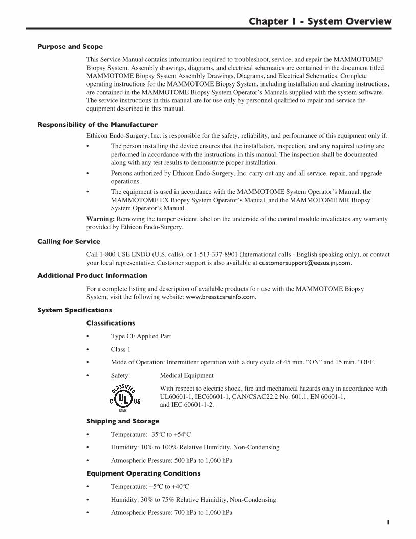
Purpose and Scope
This Service Manual contains information required to troubleshoot, service, and repair the MAMMOTOME®
Biopsy System. Assembly drawings, diagrams, and electrical schematics are contained in the document titledMAMMOTOME Biopsy System Assembly Drawings, Diagrams, and Electrical Schematics. Completeoperating instructions for the MAMMOTOME Biopsy System, including installation and cleaning instructions,are contained in the MAMMOTOME Biopsy System Operator’s Manuals supplied with the system software.The service instructions in this manual are for use only by personnel qualified to repair and service theequipment described in this manual.
Responsibility of the Manufacturer
Ethicon Endo-Surgery, Inc. is responsible for the safety, reliability, and performance of this equipment only if:
• The person installing the device ensures that the installation, inspection, and any required testing areperformed in accordance with the instructions in this manual. The inspection shall be documentedalong with any test results to demonstrate proper installation.
• Persons authorized by Ethicon Endo-Surgery, Inc. carry out any and all service, repair, and upgradeoperations.
• The equipment is used in accordance with the MAMMOTOME System Operator’s Manual. theMAMMOTOME EX Biopsy System Operator’s Manual, and the MAMMOTOME MR BiopsySystem Operator’s Manual.
Warning: Removing the tamper evident label on the underside of the control module invalidates any warrantyprovided by Ethicon Endo-Surgery.
Calling for Service
Call 1-800 USE ENDO (U.S. calls), or 1-513-337-8901 (International calls - English speaking only), or contact your local representative. Customer support is also available at [email protected].
Additional Product Information
For a complete listing and description of available products fo r use with the MAMMOTOME Biopsy System, visit the following website: www.breastcareinfo.com.
System Specifications
Classifications
• Type CF Applied Part
• Class 1
• Mode of Operation: Intermittent operation with a duty cycle of 45 min. “ON” and 15 min. “OFF.
• Safety: Medical Equipment
With respect to electric shock, fire and mechanical hazards only in accordance with UL60601-1, IEC60601-1, CAN/CSAC22.2 No. 601.1, EN 60601-1, and IEC 60601-1-2.
Shipping and Storage
• Temperature: -35ºC to +54ºC
• Humidity: 10% to 100% Relative Humidity, Non-Condensing
• Atmospheric Pressure: 500 hPa to 1,060 hPa
Equipment Operating Conditions
• Temperature: +5ºC to +40ºC
• Humidity: 30% to 75% Relative Humidity, Non-Condensing
• Atmospheric Pressure: 700 hPa to 1,060 hPa
1
MAMMOTOME Biopsy System Service Manual
2
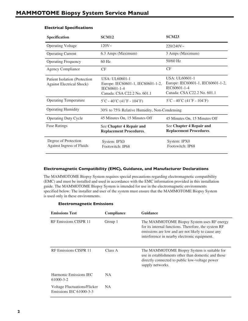
Electrical Specifications
Electromagnetic Compatibility (EMC), Guidance, and Manufacturer Declarations
The MAMMOTOME Biopsy System requires special precautions regarding electromagnetic compatibility (EMC) and must be installed and used in accordance with the EMC information provided in this installation guide. The MAMMOTOME Biopsy System is intended for use in the electromagnetic environments specified below. The installer and user of the system must ensure that the MAMMOTOME Biopsy System is used only in these environments.
Electromagnetic Emissions
Emissions Test Compliance Guidance
RF Emissions CISPR 11 Group 1 The MAMMOTOME Biopsy System uses RF energyfor its internal functions. Therefore, the system RFemissions are low and are not likely to cause anyinterference in nearby electronic equipment.
RF Emissions CISPR 11 Class A The MAMMOTOME Biopsy System is suitable foruse in establishments other than domestic and thosedirectly connected to public low-voltage powersupply networks.
Harmonic Emissions IEC61000-3-2
NA
Voltage Fluctuations/FlickerEmissions IEC 61000-3-3
NA
See Chapter 4 Repair andReplacement Procedures.
See Chapter 4 Repair andReplacement Procedures.
Specification SCM12 SCM23
Operating Voltage 120V~ 220/240V~
Operating Current 6.3 Amps (Maximum) 3 Amps (Maximum)
Operating Frequency
Patient Isolation (Protection Against Electrical Shock)
60 Hz 50/60 Hz
CF CFAgency Compliance
USA: UL60601-1Europe: IEC60601-1, IEC60601-1-2,IEC60601-1-4Canada: CSA C22.2 No. 601.1
USA: UL60601-1Europe: IEC60601-1, IEC60601-1-2,IEC60601-1-4Canada: CSA C22.2 No. 601.1
Operating Temperature
Operating Duty Cycle
Fuse Ratings
5˚C - 40˚C (41˚F - 104˚F)
45 Minutes On, 15 Minutes Off
5˚C - 40˚C (41˚F - 104˚F)
45 Minutes On, 15 Minutes Off
Operating Humidity 30% to 75% Relative Humidity, Non-Condensing
Degree of ProtectionAgainst Ingress of Fluids
System: IPX0Footswitch: IP68
System: IPX0Footswitch: IP68
Chapter 1 - System Overview
3
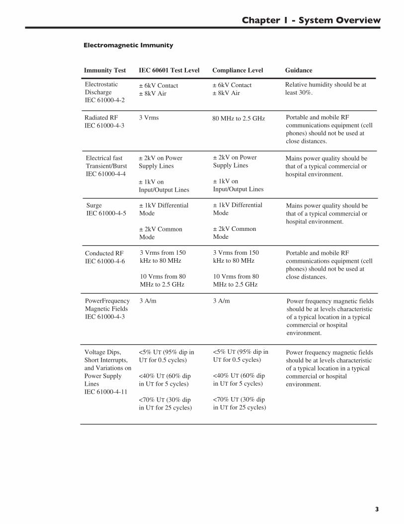
Immunity Test IEC 60601 Test Level Guidance
ElectrostaticDischargeIEC 61000-4-2
± 6kV Contact± 8kV Air
Relative humidity should be atleast 30%.
Compliance Level
± 6kV Contact± 8kV Air
Radiated RFIEC 61000-4-3
3 Vrms 80 MHz to 2.5 GHz
Electrical fastTransient/BurstIEC 61000-4-4
± 2kV on PowerSupply Lines
± 1kV onInput/Output Lines
Mains power quality should bethat of a typical commercial orhospital environment.
± 2kV on PowerSupply Lines
± 1kV onInput/Output Lines
SurgeIEC 61000-4-5
± 1kV DifferentialMode
± 2kV CommonMode
Mains power quality should bethat of a typical commercial orhospital environment.
± 1kV DifferentialMode
± 2kV CommonMode
Conducted RFIEC 61000-4-6
3 Vrms from 150kHz to 80 MHz
10 Vrms from 80MHz to 2.5 GHz
Portable and mobile RFcommunications equipment (cellphones) should not be used atclose distances.
3 Vrms from 150kHz to 80 MHz
10 Vrms from 80MHz to 2.5 GHz
PowerFrequencyMagnetic FieldsIEC 61000-4-3
3 A/m Power frequency magnetic fieldsshould be at levels characteristicof a typical location in a typicalcommercial or hospitalenvironment.
Portable and mobile RFcommunications equipment (cellphones) should not be used atclose distances.
3 A/m
Voltage Dips,Short Interrupts,and Variations onPower SupplyLinesIEC 61000-4-11
<5% UT (95% dip inUT for 0.5 cycles)
<40% UT (60% dipin UT for 5 cycles)
<70% UT (30% dipin UT for 25 cycles)
Power frequency magnetic fieldsshould be at levels characteristicof a typical location in a typicalcommercial or hospitalenvironment.
<5% UT (95% dip inUT for 0.5 cycles)
<40% UT (60% dipin UT for 5 cycles)
<70% UT (30% dipin UT for 25 cycles)
Electromagnetic Immunity

MAMMOTOME Biopsy System Service Manual
4
How Supplied
The MAMMOTOME Holster, MAMMOTOME Control Module with SMARTVAC®, MAMMOTOMEFootswitch, MAMMOTOMESupport Arm, MAMMOTOME Cart, MAMMOTOME Remote Keypad, andMAMMOTOMESoftware Package are supplied non-sterile. Dispose of these devices and all accessories inaccordance with applicable local regulations. For information on material content, contact Ethicon Endo-Surgery, Inc.
Safety Information/Warnings and Precautions
Warning - Risk of Fire
• Replace fuses as marked. Refer to Chapter 4 Repair and Replacement Procedures for fusespecifications and location.
Warning - Electric Shock Hazard
• Always disconnect the device from the electrical power source before cleaning or servicing.
• High voltages may be present on surfaces inside the control module. Never touch an exposedconductive surface while the cover is removed and the unit is energized.
Caution - ESD Sensitive Components
• The MAMMOTOME Biopsy System contains components that are sensitive to electrostaticdischarge (ESD). Proper ESD precautions must be taken while servicing the MAMMOTOMEBiopsy System. A grounded wrist strap must be worn at all times. Repair work must be done at astatic controlled workstation. Use an antistatic container for the transport of ESD sensitive circuitboards and components.
Caution - Servicing by Qualified Personnel Only
• To reduce the risk of electric shock, do not remove protective housing. Servicing should beperformed by qualified personnel only.
5
Chapter 1 - System Overview
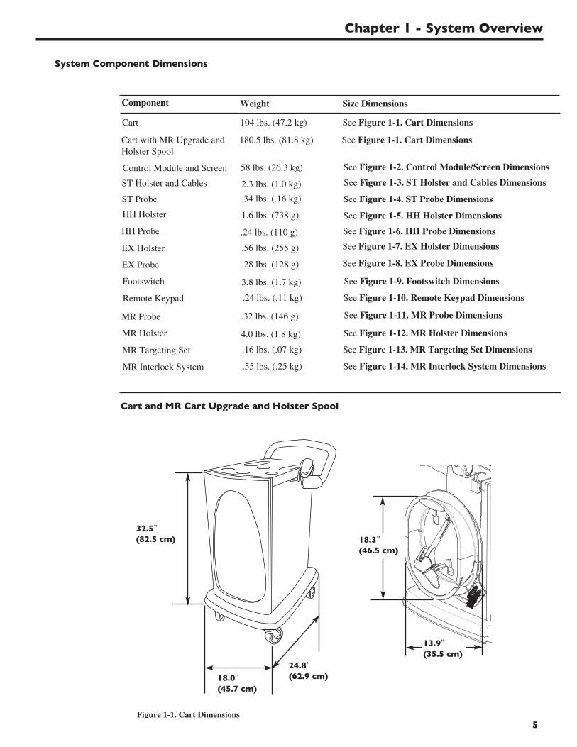
System Component Dimensions
Component
Control Module and Screen
Footswitch
Cart
ST Holster and Cables
HH Holster
Remote Keypad
32.5"(82.5 cm)
18.0"(45.7 cm)
24.8"(62.9 cm)
Figure 1-1. Cart Dimensions
Cart and MR Cart Upgrade and Holster Spool
HH Probe
ST Probe
Weight
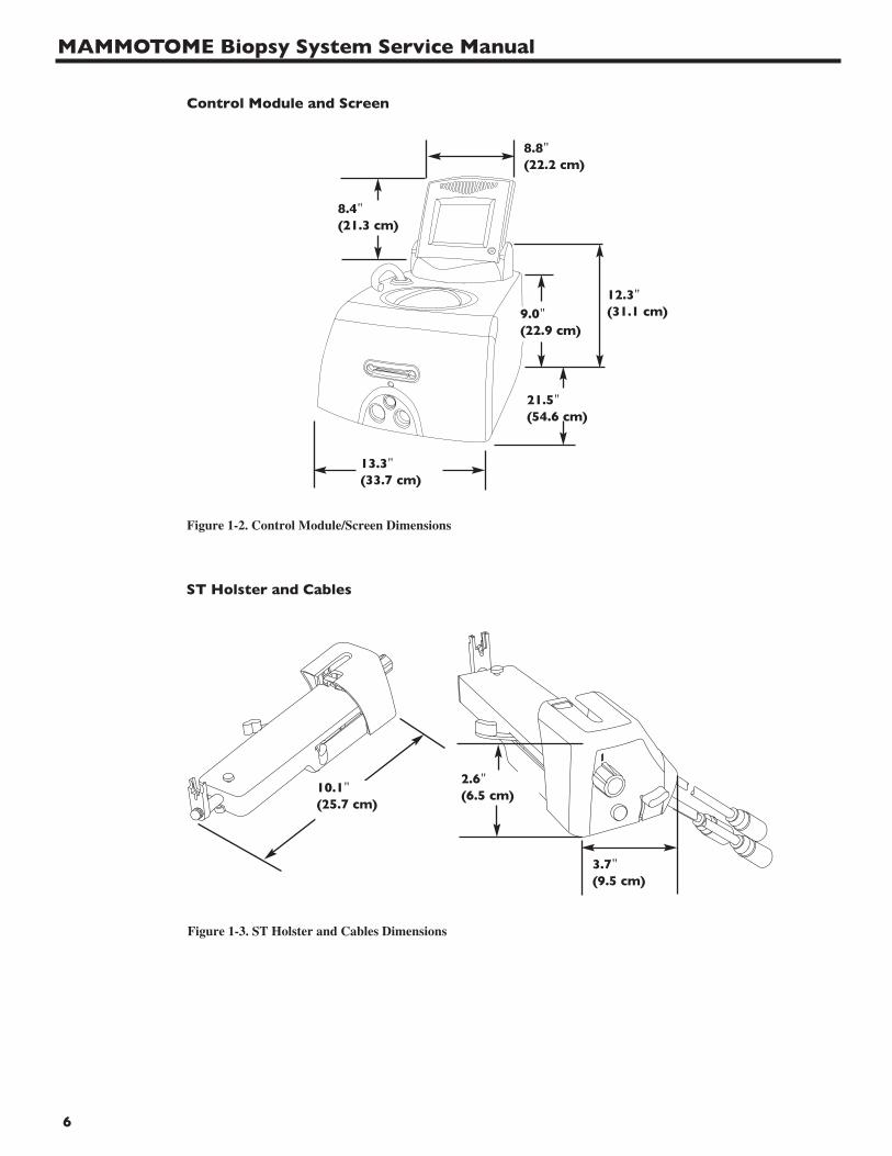
58 lbs. (26.3 kg)
3.8 lbs. (1.7 kg)
104 lbs. (47.2 kg)
2.3 lbs. (1.0 kg)
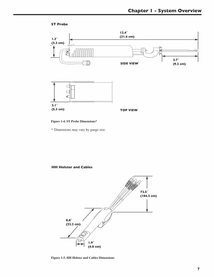
1.6 lbs. (738 g)
.24 lbs. (.11 kg)
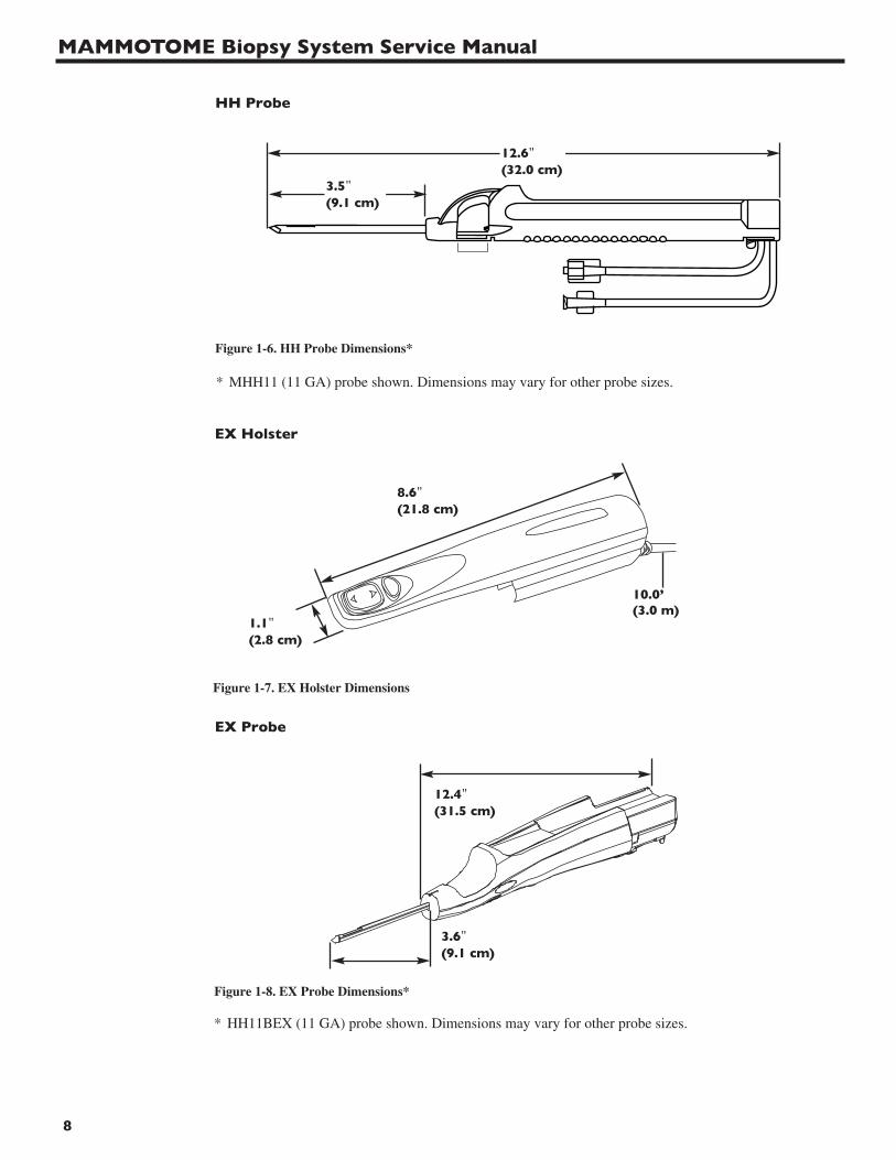
.24 lbs. (110 g)
.34 lbs. (.16 kg)
Size Dimensions
See Figure 1-1. Cart Dimensions
See Figure 1-2. Control Module/Screen Dimensions
See Figure 1-3. ST Holster and Cables Dimensions
See Figure 1-4. ST Probe Dimensions
See Figure 1-5. HH Holster Dimensions
See Figure 1-6. HH Probe Dimensions
See Figure 1-9. Footswitch Dimensions
See Figure 1-10. Remote Keypad Dimensions
EX Holster
.28 lbs. (128 g) See Figure 1-8. EX Probe DimensionsEX Probe
.56 lbs. (255 g) See Figure 1-7. EX Holster Dimensions
Cart with MR Upgrade andHolster Spool
180.5 lbs. (81.8 kg) See Figure 1-1. Cart Dimensions
MR Holster
MR Targeting Set
4.0 lbs. (1.8 kg)
.16 lbs. (.07 kg)
See Figure 1-12. MR Holster Dimensions
See Figure 1-13. MR Targeting Set Dimensions
.32 lbs. (146 g) See Figure 1-11. MR Probe DimensionsMR Probe
18.3"(46.5 cm)
13.9"(35.5 cm)
MR Interlock System .55 lbs. (.25 kg) See Figure 1-14. MR Interlock System Dimensions
MAMMOTOME Biopsy System Service Manual
6
Control Module and Screen
13.3"(33.7 cm)
9.0"(22.9 cm)
12.3"(31.1 cm)
21.5"(54.6 cm)
8.4"(21.3 cm)
8.8"(22.2 cm)
Figure 1-2. Control Module/Screen Dimensions
2.6"(6.5 cm)
3.7"(9.5 cm)
ST Holster and Cables
Figure 1-3. ST Holster and Cables Dimensions
10.1"(25.7 cm)
7
Chapter 1 - System Overview
ST Probe
12.4"(31.4 cm)
1.3"(3.2 cm)
2.1"(5.3 cm)
SIDE VIEW
TOP VIEW
Figure 1-4. ST Probe Dimensions*
Figure 1-5. HH Holster and Cables Dimensions
8.8"(22.2 cm)
72.5"(184.2 cm)
1.9"(4.8 cm)
HH Holster and Cables
3.7"(9.2 cm)
* Dimensions may vary by gauge size.
MAMMOTOME Biopsy System Service Manual
8
12.6"(32.0 cm)
3.5"(9.1 cm)
HH Probe
Figure 1-6. HH Probe Dimensions*
* MHH11 (11 GA) probe shown. Dimensions may vary for other probe sizes.
Figure 1-7. EX Holster Dimensions
Figure 1-8. EX Probe Dimensions*
EX Holster
EX Probe
* HH11BEX (11 GA) probe shown. Dimensions may vary for other probe sizes.
8.6"(21.8 cm)
1.1"(2.8 cm)
10.0’(3.0 m)
3.6"(9.1 cm)
12.4"(31.5 cm)
9
Chapter 1 - System Overview
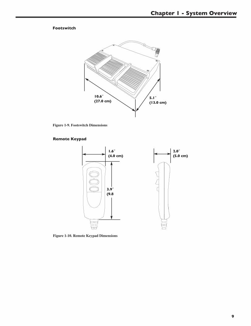
Footswitch
10.6"(27.0 cm)
5.1"(13.0 cm)
Figure 1-9. Footswitch Dimensions
Remote Keypad
1.6"(4.0 cm)
3.9"(9.8
2.0"(5.0 cm)
Figure 1-10. Remote Keypad Dimensions
MAMMOTOME Biopsy System Service Manual
10
11.3"(28.7 cm)
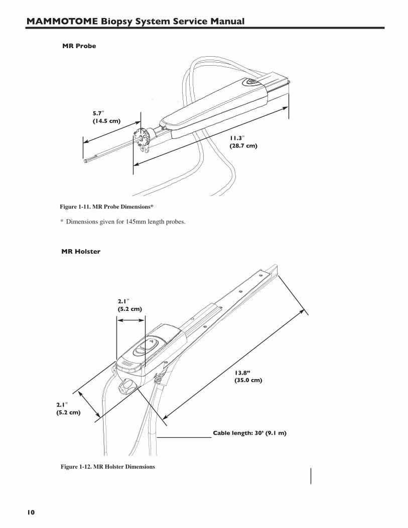
MR Probe
Figure 1-11. MR Probe Dimensions*
* Dimensions given for 145mm length probes.
Figure 1-12. MR Holster Dimensions
MR Holster
2.1"(5.2 cm)
13.8”(35.0 cm)
2.1"(5.2 cm)
Cable length: 30’ (9.1 m)
5.7"(14.5 cm)
11
Chapter 1 - System Overview
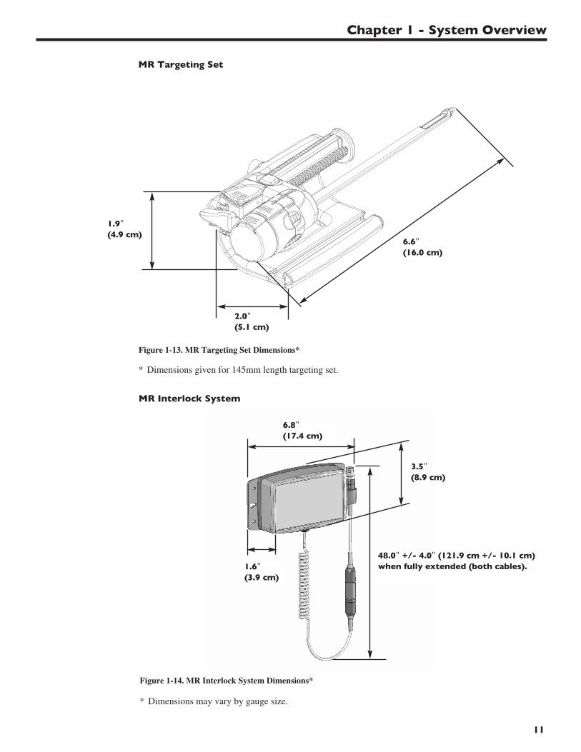
Figure 1-13. MR Targeting Set Dimensions*
MR Targeting Set
* Dimensions given for 145mm length targeting set.
2.0"(5.1 cm)
6.6"(16.0 cm)
Figure 1-14. MR Interlock System Dimensions*
MR Interlock System
* Dimensions may vary by gauge size.
1.6"(3.9 cm)
6.8"(17.4 cm)
1.9"(4.9 cm)
3.5"(8.9 cm)
48.0" +/- 4.0" (121.9 cm +/- 10.1 cm) when fully extended (both cables).

MAMMOTOME Biopsy System Service Manual
12
13
Chapter 2 - Theory of Operation
Introduction
Chapter 2 Theory of Operation describes the electronic design of the control module, including systemlayout, board-to-board interfaces, electronic hardware/software interfaces, and detailed hardware design.
Electrical System Design Specifications
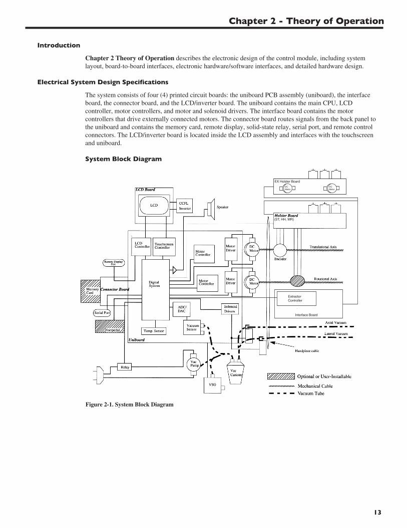
The system consists of four (4) printed circuit boards: the uniboard PCB assembly (uniboard), the interfaceboard, the connector board, and the LCD/inverter board. The uniboard contains the main CPU, LCDcontroller, motor controllers, and motor and solenoid drivers. The interface board contains the motorcontrollers that drive externally connected motors. The connector board routes signals from the back panel tothe uniboard and contains the memory card, remote display, solid-state relay, serial port, and remote controlconnectors. The LCD/inverter board is located inside the LCD assembly and interfaces with the touchscreenand uniboard.
System Block Diagram
Figure 2-1. System Block Diagram
MAMMOTOME Biopsy System Service Manual
14
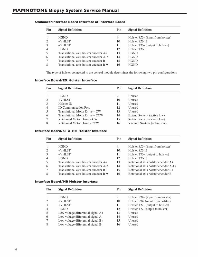
Uniboard/Interface Board Interface at Interface Board
Pin Signal Definition Pin Signal Definition
1 HGND 9 Holster RX+ (input from holster)2 +VHLST 10 Holster RX-113 +VHLST 11 Holster TX+ (output to holster)4 HGND 12 Holster TX-135 Translational axis holster encoder A+ 13 HGND6 Translational axis holster encoder A-7 14 HGND7 Translational axis holster encoder B+ 15 HGND8 Translational axis holster encoder B-9 16 HGND
The type of holster connected to the control module determines the following two pin configurations.
Interface Board/EX Holster Interface
Pin Signal Definition Pin Signal Definition
1 HGND 9 Unused2 +VHLST 10 Unused3 Holster ID 11 Unused4 ID Communication Port 12 Unused5 Translational Motor Drive – CW 13 Unused6 Translational Motor Drive – CCW 14 Extend Switch- (active low)7 Rotational Motor Drive – CW 15 Retract Switch- (active low)8 Rotational Motor Drive - CCW 16 Vacuum Switch- (active low)
Interface Board/ST & HH Holster Interface
Pin Signal Definition Pin Signal Definition
1 HGND 9 Holster RX+ (input from holster)2 +VHLST 10 Holster RX-113 +VHLST 11 Holster TX+ (output to holster)4 HGND 12 Holster TX-135 Translational axis holster encoder A+ 13 Rotational axis holster encoder A+6 Translational axis holster encoder A-7 14 Rotational axis holster encoder A-157 Translational axis holster encoder B+ 15 Rotational axis holster encoder B+8 Translational axis holster encoder B-9 16 Rotational axis holster encoder B
Interface Board/MR Holster Interface
Pin Signal Definition Pin Signal Definition
1 HGND 9 Holster RX+ (input from holster)2 +VHLST 10 Holster RX- (input from holster)3 +VHLST 11 Holster TX+ (output to holster)4 HGND 12 Holster TX- (output to holster)5 Low voltage differential signal A+ 13 Unused6 Low voltage differential signal A- 14 Unused7 Low voltage differential signal B+ 15 Unused8 Low voltage differential signal B- 16 Unused

15
Uniboard/Connector Board Interface
The uniboard to connector board interface is a 120-pin board-to-board connector with the following signals.
• 8, UART signals
• 6, footpedal signals
• 10, remote display signals
• 16, data signals for memory card
• 26, address signals for memory card
• 10, control / status signals to / from memory card
• 39, signal grounds (LGND)
• 2, VCC_CARD
• 1, +5V_CTRL
• 1, +5V_FOOT
• 1, relay drive signal
Uniboard/LCD Board Interface
The uniboard to LCD interface consists of two (2) 26-pin connectors: one for the LCD (J6) and one for theinverter, touchscreen, and LED signals (J7).
LCD Connector (J6):
• 20, LCD Control Signals
• 4, signal grounds (LGND)
• 2, +5V_DISP
Inverter/Touchscreen/LED Connector (J7):
• 3, +12V
• 3, signal grounds (LGND)
• 1, LED on/off control signal
• 1, backlight inverter on/off control signal
• 1, backlight inverter brightness control
• 4, touchscreen signals
Note: The 13 signal grounds shown are not routed in the cable. A 13-pin cable is used for the inverter, touchscreen, and LED signals.
Uniboard Definition
The uniboard contains the main CPU, LCD controller, motor controllers, and motor and solenoid drivers. TwoPLDs are used for glue logic and memory mapped I/O.
Grounding Scheme
• LGND = digital ground
• A = analog ground
• HGND = holster ground (this is the isolated holster ground)
• PGND = power ground
• VGND = video ground (this is a separate return for the red, green, and blue remote display signals and is tied to LGND near the LCD controller).
Chapter 2 - Theory of Operation

MAMMOTOME Biopsy System Service Manual
16
Power Distribution
• +5V_ANLG: +5V for sensitive analog circuits.
• +5V_CTRL: +5V for general digital and analog circuits.
• +5V_DISP: +5V for LCD display.
• +5V_FOOT: +5V for footpedal.
• +3.3V_CTRL: +3.3V for digital circuits.
• +12V: +12V for FET drivers and CCFT backlight inverter.
• +48V_FILT: Filtered +48V for motors, solenoids and driver circuitry.
• +VHLST: Holster supply voltage, 6.0V to 7.5V.
• VCC_CARD: Either 3.3V or 5.5V depending on the memory card inserted.
CPU
The CPU is a Motorola Coldfire (5206e) running at 40MHz.
UARTS
• UART 1 = holster
• UART 2 = touchscreen
Interrupts
• irq1 = translational motor controller
• irq4 = rotational motor controller
• irq7 = DUART channel A
Memory
EPROM
The EPROM is a single 4 Mbit (256K x 16) component. The CPU performs 6 wait-state reads to it. A chip select and output enable are the control signals for the EPROM.
System Flash
The Flash ROM consists of four (4) 14 Mbit (2M x 8) components for a total of 8 Mbytes. The CPU performs 5 wait-state reads and 5 wait-state writes. A chip select, write enable, and output enable are the control signals for the Flash ROM.
System DRAM
The system DRAM consists of two (2) 4 Mb x 16 components. The CPU performs 5 clock cycle reads and 5 clock cycle writes. A column, row address strobe, and write enable are the control signals for the system DRAM.
Touchscreen Controller
The touchscreen controller is a PIC microcontroller running at 4 MHz that communicates with the main microcontroller through a UART.
Digital to Analog Converter
There are two digital to analog converters (DACs): a parallel DAC and a I2C ADC/DAC. The parallel DAC is used in the following manner:
• DACA sets the backlight brightness level.
• DACB sets the translational motor current limit threshold.
• DACC sets the rotational motor current limit threshold.
17
Component Size Organization Speed (ns)
• EPROM 512 Kbyte 256K x 16 150
• System Flash 8 Mb (expandable to 16M)
• 4 (2M x 8) = 2M x 32 90
• System DRAM 15 Mb 2 (4M x 16) = 4M x 32 50
Analog to Digital Converter
The I2C ADC/DAC is a Philips, PCF8921AT. The I2C address is equal to 0 (A2 = 0,
A1 = 0, A0 = 1). The I2C ADC/DAC is used for the following:
• DAC sets the vacuum system regulation value.
• ADC0 reads the vacuum pressure value.
• ADC1 is a spare.
• ADC2 reads the translational motor current.
• ADC3 reads the rotational motor current.
Temperature Sensor
The temperature sensor is a National, LM75CIM-5 I2C device. The I2C address is equal to 1 (A2 = 0, A1 = 0, A0 = 1)
LCD and Remote Display
The LCD is a 65640 x 480 TFT display. The remote display port can support standard CRTs with a 15-pin high-density subminiature D-style connector.
Speaker
The speaker is used for error and user interface tones. The National, LM4871 uses a 1W audio amplifier.
Relay
The AC power supplied to the vacuum pump is controlled by a solid-state relay. The relay is controlled by the microcontroller through the PLD.
Serial Port
The serial port allows a PC to communicate with the microprocessor. This consists of a DB-9 connector and standard RS-232 signals.
Footswitch/Remote Keypad
The remote control port allows a footswitch or remote keypad to be used with the control module. Theremote control signals are available to the microprocessor through the PLD. Four signals are used for remote control status and two signals are used for remote control identification.
Chapter 2 - Theory of Operation
MAMMOTOME Biopsy System Service Manual
18
Vacuum Control System
The vacuum is controlled through a closed-loop analog control circuit consisting of a vacuum sensor, DAC, regulation circuitry, and VSO (voltage-sensitive orifice). The vacuum set-point is set by software through the DAC, and the regulating circuitry will maintain the vacuum set-point by adjusting the VSO in a closed-loop fashion. An initial reading determines the zero-vacuum offset of the system. This setting will typically be 250 mV for the Sensym, ASCX30DN sensor (8 bit ADC, 5Vreference, 0.01953 V/count). The sensor ratio is 150 mV per PSI, which is equivalent to 73.674 mV per inches of Hg. To determine inches of Hg, subtract the offset value from the ADC reading. Multiply the resulting decimal value by 19.53. Divide that result by 73.764. The result is the vacuum level in inches of Hg.
Internal Motor Control System
One motor drives the cutter rotation and another motor drives the cutter translation. The translational motor controller can receive its feedback either from the encoder in the holster or the encoder attached to the motor itself. The rotational motor controller receives its feedback from the encoder attached to the motor itself.
Internal Motor Drivers
The uniboard contains two motor drivers: one for the translational motor and one for the rotational motor. The rotational motor drive can be controlled “closed-loop” or “open-loop.” In the closed-loop case, the motor driver is controlled with the motor controller by a PWM signal via feedback from one of the encoders attached to the mechanical shaft. In the open-loop case, the rotational motor controlleris bypassed and a PWM signal generated by the PLD is sent to the rotational motor driver without encoder feedback.
External Motor Control System
An additional motor control system controls both the cutter translation and rotation through motors attached externally to the control module. Both motors are controlled through a state model which provides a time based sequence for control of both motors.
External Motor Drivers
The interface board contains two motor drivers: one for the translational motor and one for the rotational motor. Both motors are controlled through a closed loop circuitry via a PWM signal generated by the PLD.
Motor Watchdog Circuitry
A motor watchdog stops each motor in the event of a motor driver failure. The PWM signal sent to the motor driver is limited to 97% to guarantee a low pulse every PWM period. This low pulse resets a watchdog counter in the PLD. If the watchdog counter is not reset in 1 ms, a relay is switched to short the motor to stop it, similar to the brake function of the motor driver.
Real-Time Clock
The real-time clock is a Benchmarq bq4842. Before this component is successfully read, it must be written with the current date and time. This action, coupled with the clearing of the oscillator bit, starts the real-time clock and readies the watchdog module for use.
19
Introduction
Chapter 3 Troubleshooting contains helpful information for identifying and correcting MAMMOTOMESystem malfunctions. This chapter is divided into two major sections: 1) Error Codes, with associatedmessages, probable cause(s), and recommended corrective action(s); 2) Hardware Checks, includingsymptom (failure), probable cause(s), and recommended corrective action(s).
Error Codes
The following section lists the possible error conditions that may occur during operation of theMAMMOTOME System. If the information specified in this section is insufficient, call one of the followingnumbers for service, and identify the error condition (code) that occurred:
1-800-USE-ENDO (U.S. calls);
1-513-337-8901 (International calls - English speaking only).
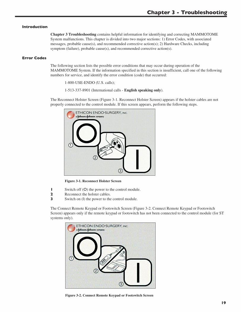
The Reconnect Holster Screen (Figure 3-1. Reconnect Holster Screen) appears if the holster cables are notproperly connected to the control module. If this screen appears, perform the following steps.
1 Switch off (O) the power to the control module.2 Reconnect the holster cables.3 Switch on (I) the power to the control module.
The Connect Remote Keypad or Footswitch Screen (Figure 3-2. Connect Remote Keypad or Footswitch Screen) appears only if the remote keypad or footswitch has not been connected to the control module (for STsystems only).
Chapter 3 - Troubleshooting
Figure 3-1. Reconnect Holster Screen
Figure 3-2. Connect Remote Keypad or Footswitch Screen
MAMMOTOME Biopsy System Service Manual
20
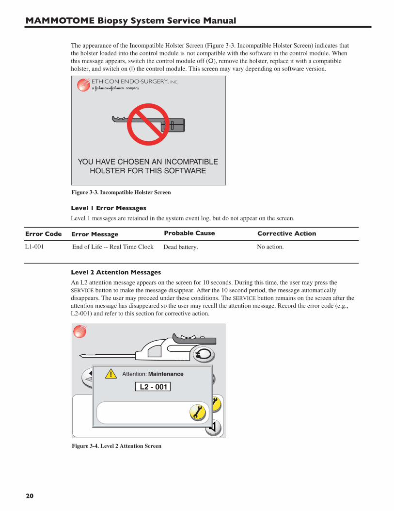
The appearance of the Incompatible Holster Screen (Figure 3-3. Incompatible Holster Screen) indicates that the holster loaded into the control module is not compatible with the software in the control module. When this message appears, switch the control module off (O), remove the holster, replace it with a compatible holster, and switch on (I) the control module. This screen may vary depending on software version.
Level 1 Error Messages
Level 1 messages are retained in the system event log, but do not appear on the screen.
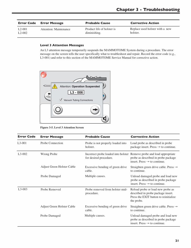
Level 2 Attention Messages
An L2 attention message appears on the screen for 10 seconds. During this time, the user may press theSERVICE button to make the message disappear. After the 10 second period, the message automaticallydisappears. The user may proceed under these conditions. The SERVICE button remains on the screen after theattention message has disappeared so the user may recall the attention message. Record the error code (e.g.,L2-001) and refer to this section for corrective action.
End of Life -- Real Time Clock Dead battery. No action.
Error Message Probable Cause Corrective ActionError Code
L1-001
Figure 3-3. Incompatible Holster Screen
Figure 3-4. Level 2 Attention Screen
21
Level 3 Attention Messages
An L3 attention message temporarily suspends the MAMMOTOME System during a procedure. The errormessage on the screen tells the user specifically what to troubleshoot and repair. Record the error code (e.g.,L3-001) and refer to this section of the MAMMOTOME Service Manual for corrective action.
Chapter 3 - Troubleshooting
Attention: Maintenance Product life of holster isdiminishing.
Replace used holster with a newholster.
Error Message Probable Cause Corrective ActionError Code
L2-001L2-002
Figure 3-5. Level 3 Attention Screen
Probe Connection Probe is not properly loaded intoholster.
Load probe as described in probepackage insert. Press → to continue.
Error Message Probable Cause Corrective ActionError Code
L3-001
Wrong Probe Incorrect probe loaded into holsterfor desired procedure.
Remove probe and load appropriateprobe as described in probe packageinsert. Press → to continue.
L3-002
Adjust Green Holster Cable Excessive bending of green drivecable.
Straighten green drive cable. Press →to continue.
Probe Damaged Multiple causes. Unload damaged probe and load newprobe as described in probe packageinsert. Press → to continue.
Probe Removed Probe removed from holster mid-procedure.
Reload probe or load new probe asdescribed in probe package insert.Press the EXIT button to reinitializethe probe.
L3-003
Adjust Green Holster Cable Excessive bending of green drivecable.
Straighten green drive cable. Press →to continue.
Probe Damaged Multiple causes. Unload damaged probe and load newprobe as described in probe packageinsert. Press → to continue.

MAMMOTOME Biopsy System Service Manual
22
Footswitch Disconnected Footswitch is not properlyconnected to control module.
Properly seat footswitch connector inback panel of control module. Press→ to continue.
L3-008
User no longer wants to usefootswitch.
1. Switch off (O) the control module.2. Disconnect the footswitch from the
control module.3. Connect the remote keypad to the
control module.4. Switch on (I) the control module.
Green Holster Cable Green drive cable connector isnot properly connected to controlmodule.
L3-009 Properly seat green drive cableconnector in control module. Press →to continue.
Probe Damaged Multiple causes. Unload damaged probe and load newprobe as described in probe packageinsert. Press the EXIT button toreinitialize the probe.
Connect green and blue connectors totheir respective connector ports. Press→ to continue.
Green drive cable connected toblue cable connector port.
Straighten green drive cable. Press →to continue.
Excessive bending of green drivecable.
Error Message Probable Cause Corrective ActionError Code
L3-004 Adjust Green Holster Cable Excessive bending of green drivecable.
Straighten green drive cable. Press →to continue.
Probe Damaged Multiple causes. Unload damaged probe and load newprobe as described in probe packageinsert. Press → to continue.
L3-005 Adjust Blue Holster Cable Excessive bending of blue drivecable.
Straighten blue drive cable. Press →to continue.
Probe Damaged Multiple causes. Reload probe or load new probe asdescribed in probe package insert.Press the EXIT button to reinitializethe probe.
L3-006 Vacuum Tubing Connections Vacuum set connection is looseor disconnected.
Check the following vacuumconnections for tightness:• Flexible tube connections at
canister lid.• Vacuum set cartridge connection.• Canister lid.Press → to continue.
L3-007 Black Holster CableDisconnected
Black electrical cable connectoron holster is not properlyconnected to control module.
Properly seat black electrical cableconnector in control module. Press →to continue.

23
Chapter 3 - Troubleshooting
Error Message Probable Cause Corrective ActionError Code
L3-010 Remote Keypad FORWARDButton Activated
FORWARD button pressed byaccident.
Release FORWARD button. Press →to continue.
L3-011 Remote Keypad REVERSEButton Activated
REVERSE button pressed byaccident.
Release REVERSE button. Press → tocontinue.
L3-012 Remote Keypad VACUUMButton Activated
VACUUM button pressed byaccident.
Release VACUUM button. Press → tocontinue.
L3-013 Footswitch FORWARD PedalActivated
FORWARD pedal pressed byaccident.
Release FORWARD pedal. Press → tocontinue.
L3-014 Footswitch REVERSE PedalActivated
REVERSE pedal pressed byaccident.
Release REVERSE pedal. Press → tocontinue.
L3-015 Footswitch VACUUM PedalActivated
VACUUM pedal pressed byaccident.
Release VACUUM pedal. Press → tocontinue.
L3-016 Incompatible Footswitch orRemote Keypad
Device other thanMAMMOTOME Footswitch orRemote Keypad is connected tothe control module’s remotecontrol socket.
Remove other device connector fromthe remote control socket and insertMAMMOTOME Footswitch orRemote Keypad connector. Press → tocontinue.
L3-017 Green Holster Cable Excessive bending of green drivecable.
Straighten green drive cable. Press →to continue.
Probe Damaged Multiple causes. Unload damaged probe and load newprobe as described in probe packageinsert. Press → to continue.
L3-018
Green drive cable connector isnot properly connected to controlmodule.
Properly seat green drive cableconnector in control module. Press →to continue.
Blue Holster Cable Excessive bending of blue drivecable.
Straighten blue drive cable. Press → tocontinue.
Probe Damaged Multiple causes. Unload damaged probe and load newprobe as described in probe packageinsert. Press → to continue.
Blue drive cable connector is notproperly connected to controlmodule.
Properly seat blue drive cableconnector in control module. Press →to continue.

MAMMOTOME Biopsy System Service Manual
24
Remote Keypad Disconnected Remote keypad is not properlyconnected to control module.
Properly seat remote keypadconnector in back panel of the controlmodule. Press → to continue.
L3-023
User no longer wants to useremote keypad.
1. Switch off (O) the control module.2. Disconnect the remote keypad
from the control module.3. Connect the footswitch to the
control module.4. Switch on (I) the control module.
Error Message Probable Cause Corrective ActionError Code
L3-019 Inadequate Airflow through Unit Airflow through control moduleis restricted beneath or at theback panel of the controlmodule.
Remove restrictive material(s) frombeneath or behind the control module.Allow sufficient time to cool. Ensurethe control module is at least 6"(15.24 cm) from all walls. Press → tocontinue.
L3-020 Adjust Blue Holster Cable Excessive bending of blue drivecable.
Straighten blue drive cable. Press →to continue.
Probe Damaged Multiple causes. Reload probe or load new probe asdescribed in probe package insert.Press → to continue.
L3-021 Vacuum Tubing Connections Vacuum set connection is looseor disconnected.
Check the following vacuumconnections for tightness:• Flexible tube connections at
canister lid.• Vacuum set cartridge connection.• Canister lid.Press → to continue.
L3-022 Pre-Fire Position Probe has not been fired. Release safety lever and press → tocontinue. Press the fire button on theST holster.

25
Remote Keypad REVERSEButton Activated
REVERSE key pressedunintentionally.
1. Release REVERSE key (button.) 2. Press → to continue.
L3-026
Remote Keypad FORWARDButton Activated
FORWARD key pressedunintentionally.
1. Release FORWARD key (button). 2. Press → to continue.
L3-025
Remote Keypad VACUUMButton Activated
VACUUM key pressedunintentionally.
1. Release VACUUM key (button).2. Press → to continue.
L3-027
Invalid Translation Move Error Translation position mismatchbetween the Uniboard and theInterface board.
Press → to continue. The cutter willautomatically retract to position 1.
L3-028
Invalid Rotation Move Error Rotation position mismatchbetween the Uniboard and theInterface board.
L3-029
Chapter 3 - Troubleshooting
Defective keypad contacts onEX Holster.
Replace circuit board on EX Holster.
Defective keypad contacts onEX Holster.
Replace circuit board on EX Holster.
Defective keypad contacts onEX Holster.
Replace circuit board on EX Holster.
Press → to continue. The cutter willautomatically retract to position 1.
Error Message Probable Cause Corrective ActionError Code

MAMMOTOME Biopsy System Service Manual
26
L3-030
L3-031
Probe Damaged Multiple possible causes:error is attributed to damageto the translation drive train.
L3-032
Probe DamagedL3-033
Invalid Translation Move Error Translation position mismatchbetween the Uniboard and theInterface board.
Press → to continue. The cutter willautomatically retract to position 1.
Invalid Rotation Move Error Rotation position mismatchbetween the Uniboard and theInterface board.
Press → to continue. The cutterwill automatically retract toposition 1.
Multiple possible causes:error is attributed to damageto the rotation drive train.
Unload damaged probe and load newprobe as described in probe packageinsert. Press → to continue.
Unload damaged probe and load newprobe as described in probe packageinsert. Press → to continue.
Error Message Probable Cause Corrective ActionError Code
27
Chapter 3 - Troubleshooting
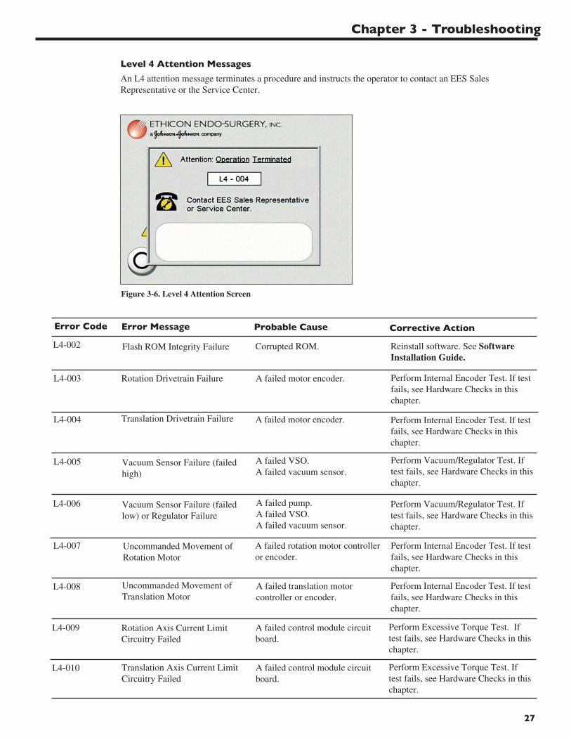
Level 4 Attention Messages
An L4 attention message terminates a procedure and instructs the operator to contact an EES SalesRepresentative or the Service Center.
Flash ROM Integrity Failure Corrupted ROM. Reinstall software. See SoftwareInstallation Guide.
L4-002
Error Message Probable Cause Corrective ActionError Code
Rotation Drivetrain Failure A failed motor encoder.L4-003
Vacuum Sensor Failure (failedhigh)
A failed VSO.A failed vacuum sensor.
L4-005
Translation Drivetrain Failure A failed motor encoder. Perform Internal Encoder Test. If testfails, see Hardware Checks in thischapter.
L4-004
Vacuum Sensor Failure (failedlow) or Regulator Failure
A failed pump.A failed VSO.A failed vacuum sensor.
Perform Vacuum/Regulator Test. Iftest fails, see Hardware Checks in thischapter.
L4-006
Figure 3-6. Level 4 Attention Screen
Uncommanded Movement ofRotation Motor
A failed rotation motor controlleror encoder.
L4-007
Uncommanded Movement ofTranslation Motor
A failed translation motorcontroller or encoder.
Perform Internal Encoder Test. If testfails, see Hardware Checks in thischapter.
L4-008
Rotation Axis Current LimitCircuitry Failed
A failed control module circuitboard.
Perform Excessive Torque Test. Iftest fails, see Hardware Checks in thischapter.
L4-009
Translation Axis Current LimitCircuitry Failed
A failed control module circuitboard.
Perform Excessive Torque Test. Iftest fails, see Hardware Checks in thischapter.
L4-010
Perform Internal Encoder Test. If testfails, see Hardware Checks in thischapter.
Perform Vacuum/Regulator Test. Iftest fails, see Hardware Checks in thischapter.
Perform Internal Encoder Test. If testfails, see Hardware Checks in thischapter.

MAMMOTOME Biopsy System Service Manual
28
Translational axis motor watchdogexpired.
Failed watchdog reset (cyclepower on system).Failed motor circuitry.
L4-023
Rotational axis motor watchdogexpired.
Failed watchdog reset (cyclepower on system).Failed motor circuitry.
Cycle system power.Perform Internal Encoder Test. If testfails, see Hardware Checks in thischapter.
L4-024
Error Message Probable Cause Corrective ActionError Code
Rotation Axis Motor DriverMonitoring Circuit Failed
A failed control module circuitboard.
Replace uniboard PCB assembly. SeeChapter 4 Repair and ReplacementProcedures.
L4-011
Translation Axis Motor DriverMonitoring Circuit Failed
A failed control module circuitboard.
Replace uniboard PCB assembly. SeeChapter 4.
Motor Uninitialized An invalid jump in the software.L4-013
Sequence Fail: Brake Release An invalid jump in the software.L4-014
Sequence Fail: Brake Set An invalid jump in the software.L4-015
Safety Variable Corruption Corrupted RAM.L4-016
Sequence Fail: Position Error An invalid jump in the software.L4-017
Sequence Fail: Motor Start An invalid jump in the software.L4-018
Sequence Fail: Motor Stop An invalid jump in the software.L4-019
Sequence Fail: Current Limit An invalid jump in the software.L4-020
Sequence Fail: Vacuum An invalid jump in the software.L4-021
Sequence Fail: Motor PWMSelect/Enable
An invalid jump in the software. Reinstall software. See SoftwareInstallation Guide. Replace uniboardPCB assembly. See Chapter 4.
L4-022
Cycle system power.Perform Internal Encoder Test. If testfails, see Hardware Checks in thischapter.
Reinstall software. See SoftwareInstallation Guide. Replace uniboardPCB assembly. See Chapter 4.
Reinstall software. See SoftwareInstallation Guide. Replace uniboardPCB assembly. See Chapter 4.
Reinstall software. See SoftwareInstallation Guide. Replace uniboardPCB assembly. See Chapter 4.
Reinstall software. See SoftwareInstallation Guide. Replace uniboardPCB assembly. See Chapter 4.
Reinstall software. See SoftwareInstallation Guide. Replace uniboardPCB assembly. See Chapter 4.
Reinstall software. See SoftwareInstallation Guide. Replace uniboardPCB assembly. See Chapter 4.
Reinstall software. See SoftwareInstallation Guide. Replace uniboardPCB assembly. See Chapter 4.
Reinstall software. See SoftwareInstallation Guide. Replace uniboardPCB assembly. See Chapter 4.
Reinstall software. See SoftwareInstallation Guide. Replace uniboardPCB assembly. See Chapter 4.
L4-012
29
Chapter 3 - Troubleshooting
POST ERROR - RAM Failure. Corrupted RAM in Interfaceboard.
L4-025 Cycle system power and allow theInterface board to perform a PowerOn Self Test. Replace the Interfaceboard assembly if the test fails.
Error Message Probable Cause Corrective ActionError Code
POST ERROR - CPLD Failure. Failure in the ComplexProgrammable Logic Device ofthe Interface board.
L4-026 Cycle system power and allow theInterface board to perform a PowerOn Self Test. Replace the Interfaceboard assembly if the test fails.
POST ERROR - ID Chip Failure. Failure in the ID Chip of theInterface board.
L4-027 Cycle system power and allow theInterface board to perform a PowerOn Self Test. Replace the Interfaceboard assembly if the test fails.
Programming Checksum Error. An invalid jump in the softwareon the Interface board.
L4-028 Cycle system power and allow theInterface board to perform a PowerOn Self Test. Replace the Interfaceboard assembly if the test fails.
Programming Block SequenceCompromised.
L4-029 Cycle system power and allow theInterface board to perform a PowerOn Self Test. Replace the Interfaceboard assembly if the test fails.
Programming AbortedPrematurely.
L4-030 Cycle system power and allow theInterface board to perform a PowerOn Self Test. Replace the Interfaceboard assembly if the test fails.
Translation Motor Failure. A failed translation motor chipon the Interface board.
L4-031 Cycle system power and allow theInterface board to perform a PowerOn Self Test. Replace the Interfaceboard assembly if the test fails.
Rotation Motor Failure. A failed rotation motor chip onthe Interface board.
L4-032 Cycle system power and allow theInterface board to perform a PowerOn Self Test. Replace the Interfaceboard assembly if the test fails.
Management Software andInterface Board SoftwareCommunication Failure.
A failure in the signal pathbetween the Uniboard and theInterface board.
L4-033 Cycle system power and allow theInterface board to perform a PowerOn Self Test. Inspect the wiringharness for continuity (Uniboard toInterface board).
L4-034
An invalid jump in the softwareon the Interface board.
An invalid jump in the softwareon the Interface board.
Control modulel Applicationsoftware and Interface BoardSoftware Communication Failure.
A failure in the signal pathbetween the Uniboard and theInterface board.
Cycle system power and allow theInterface board to perform a PowerOn Self Test. Inspect the wiringharness for continuity (Uniboard toInterface board).
MAMMOTOME Biopsy System Service Manual
30
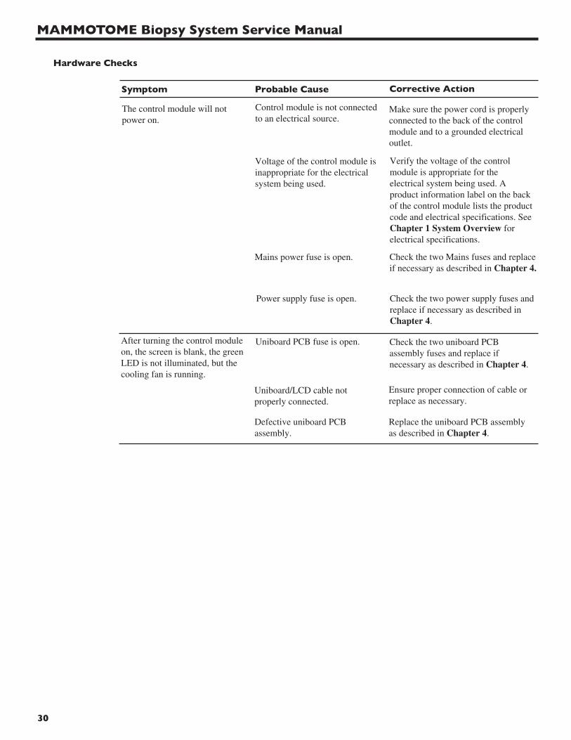
Hardware Checks
The control module will notpower on.
After turning the control moduleon, the screen is blank, the greenLED is not illuminated, but thecooling fan is running.
Voltage of the control module isinappropriate for the electricalsystem being used.
Mains power fuse is open.
Power supply fuse is open.
Uniboard PCB fuse is open.
Uniboard/LCD cable notproperly connected.
Make sure the power cord is properlyconnected to the back of the controlmodule and to a grounded electricaloutlet.
Verify the voltage of the controlmodule is appropriate for theelectrical system being used. Aproduct information label on the backof the control module lists the productcode and electrical specifications. SeeChapter 1 System Overview forelectrical specifications.
Check the two Mains fuses and replaceif necessary as described in Chapter 4.
Check the two power supply fuses andreplace if necessary as described inChapter 4.
Check the two uniboard PCBassembly fuses and replace ifnecessary as described in Chapter 4.
Ensure proper connection of cable orreplace as necessary.
Symptom Probable Cause Corrective Action
Defective uniboard PCBassembly.
Replace the uniboard PCB assemblyas described in Chapter 4.
Control module is not connectedto an electrical source.
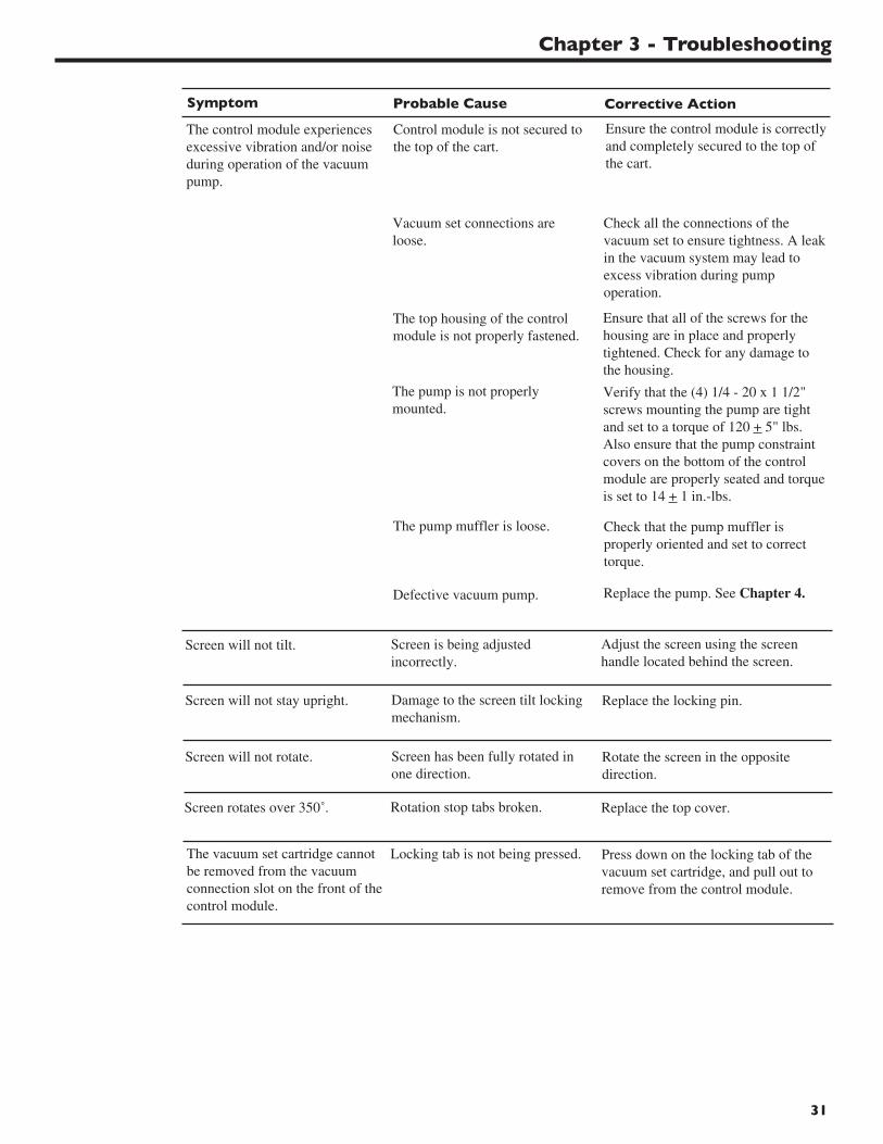
31
Screen is being adjustedincorrectly.
Damage to the screen tilt lockingmechanism.
Adjust the screen using the screenhandle located behind the screen.
Replace the locking pin.
Screen will not tilt.
Screen will not stay upright.
Screen has been fully rotated inone direction.
Locking tab is not being pressed.
Rotate the screen in the oppositedirection.
Press down on the locking tab of thevacuum set cartridge, and pull out toremove from the control module.
Screen will not rotate.
The vacuum set cartridge cannotbe removed from the vacuumconnection slot on the front of thecontrol module.
The control module experiencesexcessive vibration and/or noiseduring operation of the vacuumpump.
Control module is not secured tothe top of the cart.
Vacuum set connections areloose.
The top housing of the controlmodule is not properly fastened.
The pump is not properlymounted.
Ensure the control module is correctlyand completely secured to the top ofthe cart.
Check all the connections of thevacuum set to ensure tightness. A leakin the vacuum system may lead toexcess vibration during pumpoperation.
Verify that the (4) 1/4 - 20 x 1 1/2"screws mounting the pump are tightand set to a torque of 120 + 5" lbs. Also ensure that the pump constraintcovers on the bottom of the controlmodule are properly seated and torqueis set to 14 + 1 in.-lbs.
Ensure that all of the screws for thehousing are in place and properlytightened. Check for any damage tothe housing.
The pump muffler is loose. Check that the pump muffler isproperly oriented and set to correcttorque.
Symptom Probable Cause Corrective Action
Defective vacuum pump. Replace the pump. See Chapter 4.
Rotation stop tabs broken. Replace the top cover.Screen rotates over 350˚.
Chapter 3 - Troubleshooting
MAMMOTOME Biopsy System Service Manual
32
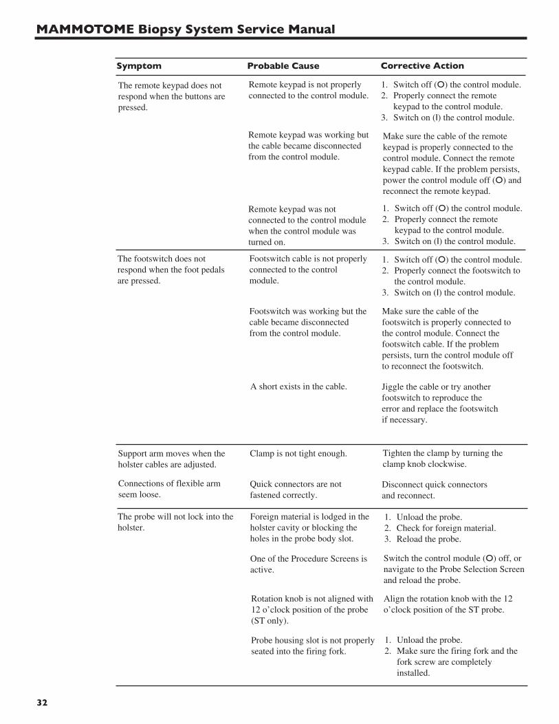
Symptom Probable Cause Corrective Action
The remote keypad does notrespond when the buttons arepressed.
Remote keypad is not properlyconnected to the control module.
Make sure the cable of the remotekeypad is properly connected to thecontrol module. Connect the remotekeypad cable. If the problem persists,power the control module off (O) andreconnect the remote keypad.
1. Switch off (O) the control module.2. Properly connect the remote
keypad to the control module.3. Switch on (I) the control module.
Remote keypad was working butthe cable became disconnectedfrom the control module.
Remote keypad was notconnected to the control modulewhen the control module wasturned on.
1. Switch off (O) the control module.2. Properly connect the remote
keypad to the control module.3. Switch on (I) the control module.
The footswitch does notrespond when the foot pedalsare pressed.
Footswitch cable is not properlyconnected to the controlmodule.
1. Switch off (O) the control module.2. Properly connect the footswitch to
the control module.3. Switch on (I) the control module.
Footswitch was working but thecable became disconnected from the control module.
Make sure the cable of thefootswitch is properly connected tothe control module. Connect thefootswitch cable. If the problempersists, turn the control module offto reconnect the footswitch.
Support arm moves when theholster cables are adjusted.
Clamp is not tight enough. Tighten the clamp by turning theclamp knob clockwise.
Quick connectors are notfastened correctly.
Disconnect quick connectors and reconnect.
Connections of flexible armseem loose.
The probe will not lock into theholster.
Foreign material is lodged in theholster cavity or blocking theholes in the probe body slot.
Switch the control module (O) off, ornavigate to the Probe Selection Screenand reload the probe.
1. Unload the probe.2. Check for foreign material.3. Reload the probe.
One of the Procedure Screens isactive.
Rotation knob is not aligned with12 o’clock position of the probe(ST only).
Align the rotation knob with the 12o’clock position of the ST probe.
Probe housing slot is not properlyseated into the firing fork.
1. Unload the probe.2. Make sure the firing fork and the
fork screw are completely installed.
A short exists in the cable. Jiggle the cable or try anotherfootswitch to reproduce theerror and replace the footswitchif necessary.

Chapter 3 - Troubleshooting
33
Symptom Probable Cause Corrective Action
The control module does notprovide any “signals” or“beeps” when the buttons onthe holster are pressed.
Footswitch is connected to thecontrol module.
1. Switch off (O) the control module.2. Disconnect the footswitch from
the control module.3. Connect the holster to the control
module.4. Switch on (I) the control module.
Control module volume isturned down.
The Reconnect Holster Screenappears on the control module.
Cables are not properlyconnected to the control module.
Switch off (O) the control module andreconnect the cables.
Cutter is within the samplenotch.
Retract the cutter proximal to thesample notch.
ST Probe cannot be removedfrom holster.
Electrical cable is loose or notconnected properly.
At the Procedure Screen, increase thevolume of the control module
Make sure the electrical cable issecurely seated in the connector porton the front of the control module.
Front wheels are locked. Unlock the cart wheels.Cart wheels will not move.

MAMMOTOME Biopsy System Service Manual
34
L3 Attention Screens for MR Systems
An L3 attention message temporarily suspends the MAMMOTOME System during a procedure. The errormessage on the screen tells the user specifically what to look for in order to rectify the situation and continuewith the procedure. Record the code (e.g., L3-006) and refer to this section for the appropriate correctiveaction.
Probe Damaged Multiple possibilities. 1. Unload damaged probe.2. Load new probe3. Press fi to continue.4. Select NEW PROBE
at the YOU HAVEEXITED THEPROCEDURE screen.
Message Possible Cause Corrective ActionCode
L3-002
Vacuum Tubing Connections Vacuum set connection isloose or disconnected.
1. Check the followingvacuum connectionsfor tightness:• Flexible tube
connections atcanister lid.
• Vacuum setcartridge connection.
• Canister lid.2. Press ⇒ to continue.
L3-006
Holster Cable Disconnected The holster is not properlyconnected to control module.
1. Properly seat holstercable connector incontrol module.
2. Press ⇒ to continue.
Holster FORWARD ButtonActivated
FORWARD key (button)pressed unintentionally.
1. Release FORWARD key(button) on holster.
2. Press ⇒ to continue.
L3-007
L3-010
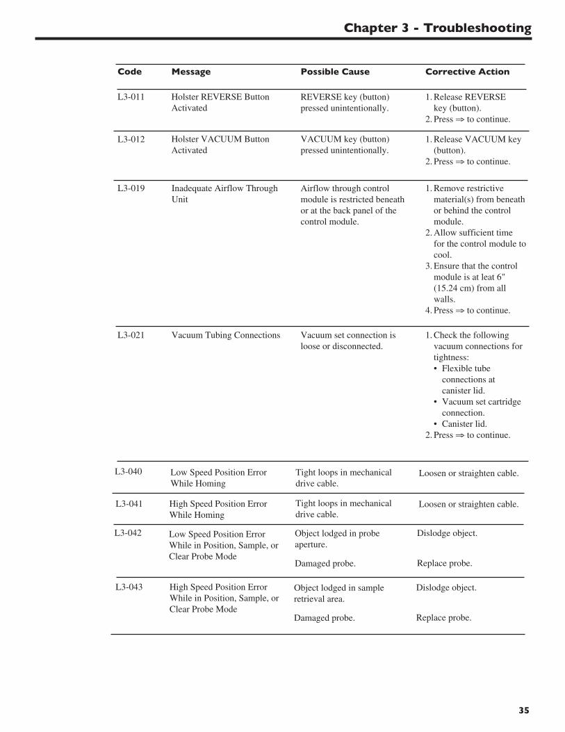
Chapter 3 - Troubleshooting
35
High Speed Position ErrorWhile Homing
L3-041
L3-042
L3-043
Low Speed Position ErrorWhile in Position, Sample, orClear Probe Mode
High Speed Position ErrorWhile in Position, Sample, orClear Probe Mode
Inadequate Airflow ThroughUnit
Airflow through controlmodule is restricted beneathor at the back panel of thecontrol module.
1. Remove restrictivematerial(s) from beneathor behind the controlmodule.
2. Allow sufficient timefor the control module tocool.
3. Ensure that the controlmodule is at leat 6"(15.24 cm) from allwalls.
4. Press ⇒ to continue.
L3-019
Vacuum Tubing Connections Vacuum set connection isloose or disconnected.
1. Check the followingvacuum connections fortightness:• Flexible tube
connections atcanister lid.
• Vacuum set cartridgeconnection.
• Canister lid.2. Press ⇒ to continue.
L3-021
Holster REVERSE ButtonActivated
REVERSE key (button)pressed unintentionally.
1. Release REVERSEkey (button).
2. Press ⇒ to continue.
Holster VACUUM ButtonActivated
VACUUM key (button)pressed unintentionally.
1. Release VACUUM key(button).
2. Press ⇒ to continue.
L3-011
L3-012
Message Possible Cause Corrective ActionCode
Loosen or straighten cable.Low Speed Position ErrorWhile Homing
L3-040 Tight loops in mechanicaldrive cable.
Loosen or straighten cable.Tight loops in mechanicaldrive cable.
Object lodged in probeaperture.
Damaged probe.
Dislodge object.
Replace probe.
Object lodged in sampleretrieval area.
Damaged probe.
Dislodge object.
Replace probe.

MAMMOTOME Biopsy System Service Manual
36
Non MRI safe input deviceconnected to control module.
Interlock box not connected.
One of the following isconnected to control module:EX holster, ST holster, HHholster, remote keypad,footswitch.
Replace incorrect holsterwith MR holster; removefootswitch or remotekeypad from ILBconnection located on theback of the controlmodule.
Interlock box not connected tocontrol module.
Connect interlock box toback of control module.
Message Possible Cause Corrective ActionCode
L3-044
L3-045
Chapter 3 - Troubleshooting
37
Cannot remove vacuum set cartridgefrom vacuum connection slot on frontof control module.
Vacuum set cartridge will notdisengage from control module.
Press down on the locking tabof the vacuum set cartridgeand pull out to remove fromcontrol module.
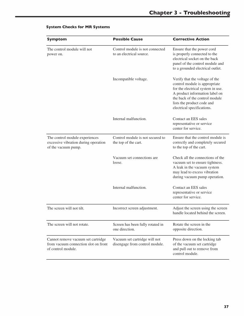
System Checks for MR Systems
The control module will notpower on.
Control module is not connectedto an electrical source.
Ensure that the power cordis properly connected to theelectrical socket on the backpanel of the control module andto a grounded electrical outlet.
Symptom Possible Cause Corrective Action
Incompatible voltage. Verify that the voltage of thecontrol module is appropriatefor the electrical system in use.A product information label onthe back of the control modulelists the product code andelectrical specifications.
Internal malfunction. Contact an EES salesrepresentative or servicecenter for service.
The control module experiencesexcessive vibration during operationof the vacuum pump.
Control module is not secured tothe top of the cart.
Ensure that the control module iscorrectly and completely securedto the top of the cart.
Vacuum set connections areloose.
Check all the connections of thevacuum set to ensure tightness.A leak in the vacuum systemmay lead to excess vibrationduring vacuum pump operation.
Internal malfunction. Contact an EES salesrepresentative or servicecenter for service.
The screen will not tilt. Incorrect screen adjustment. Adjust the screen using the screenhandle located behind the screen.
The screen will not rotate. Screen has been fully rotated inone direction.
Rotate the screen in theopposite direction.
MAMMOTOME Biopsy System Service Manual
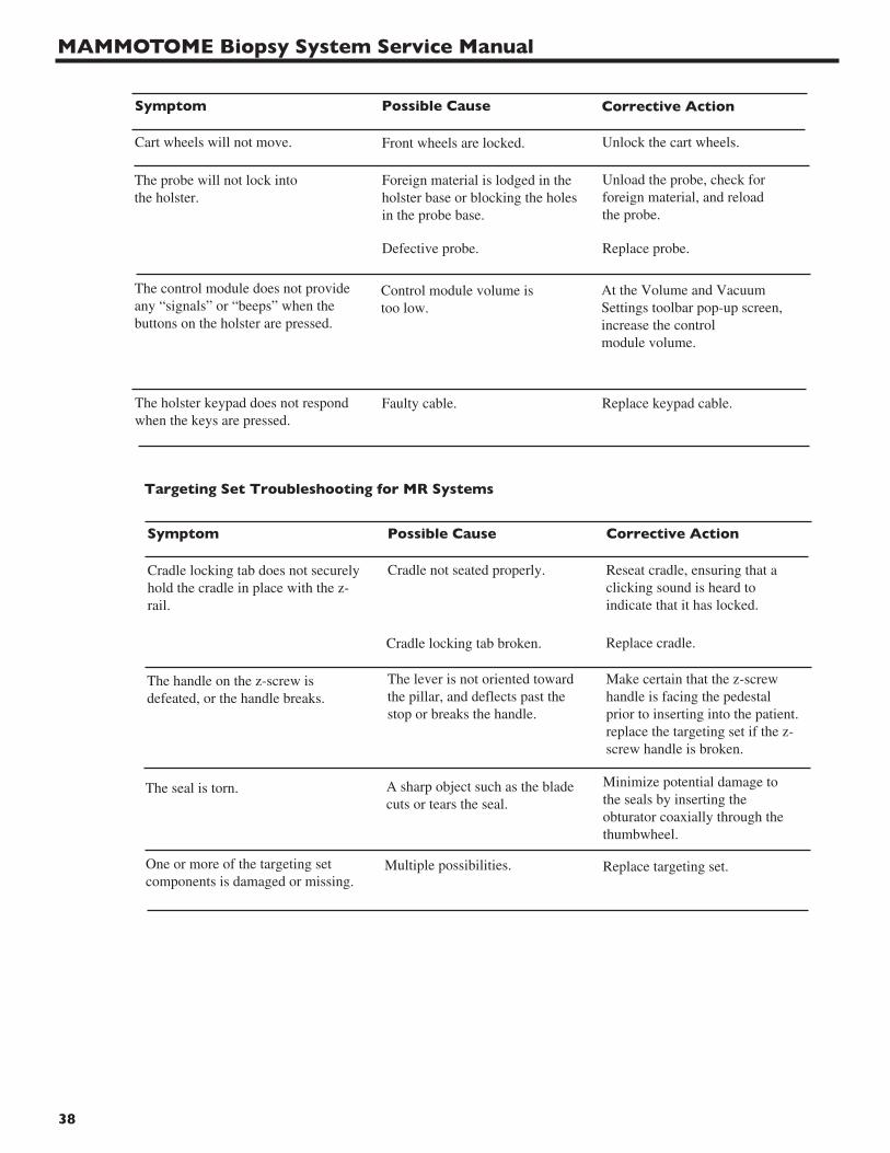
38
Cart wheels will not move. Front wheels are locked. Unlock the cart wheels.
The probe will not lock intothe holster.
Foreign material is lodged in theholster base or blocking the holesin the probe base.
Unload the probe, check forforeign material, and reloadthe probe.
The control module does not provideany “signals” or “beeps” when thebuttons on the holster are pressed.
Control module volume istoo low.
At the Volume and VacuumSettings toolbar pop-up screen,increase the controlmodule volume.
The holster keypad does not respondwhen the keys are pressed.
Faulty cable. Replace keypad cable.
Symptom Possible Cause Corrective Action
Defective probe. Replace probe.
Targeting Set Troubleshooting for MR Systems
Cradle locking tab does not securelyhold the cradle in place with the z-rail.
Cradle not seated properly. Reseat cradle, ensuring that aclicking sound is heard toindicate that it has locked.
Symptom Possible Cause Corrective Action
The lever is not oriented towardthe pillar, and deflects past thestop or breaks the handle.
Make certain that the z-screwhandle is facing the pedestalprior to inserting into the patient.replace the targeting set if the z-screw handle is broken.
The seal is torn. A sharp object such as the bladecuts or tears the seal.
Minimize potential damage tothe seals by inserting theobturator coaxially through thethumbwheel.
One or more of the targeting setcomponents is damaged or missing.
Replace targeting set.Multiple possibilities.
Cradle locking tab broken. Replace cradle.
The handle on the z-screw isdefeated, or the handle breaks.

Chapter 3 - Troubleshooting
39
The thumbwheel does not rotatefreely on the sleeve mount.
The fit of the targeting setcomponents is too tight.
If the thumbwheel does notrotate freely, replace targetingset.
The levers jam and do not release thesleeve assembly for adjustment.
If the sleeve mount cannot bepulled away from the patient bydepressing the levers, the pawlcan be rotated back anddepressed to release thetargeting rail.
The fit between the levers and thesleeve mount is too tight.
The buttons jam closed in the sleevemount, and the z-screw cannot beadjusted except by rotation.
If the buttons fail to move, rotatethe z-screw until the buttonsmove. If the buttons still fail tomove, replace targeting set.
The fit between the buttons and thesleeve mount is too tight.
The secondary z-rail slides off of theprimary rail, interfering with the boreof the magnet.
Before sliding the patient intothe magnet, always confirm thatthe patient and targeting haveclearance with respect to themagnet bore.
Spring is displaced.
The levers fail to hold the sleevemount in position on the targetingrail.
Improper aperture positionduring imaging.
Symptom Possible Cause Corrective Action
Z-screw interferes with bore ofmagnet.
If the levers are defeated and thesleeve mount moves back, andthe buttons have not beenactivated, confirm the correctorientation of the z-screw leverand push the targeting back inuntil the z-stop bottoms again.
Targeting rail fails to release. Interference between targetingset and rail.
Use the localization compressionrails to remove the targeting.Release the angulation control toensure perpendicular retraction ofthe targeting.
When properly installed, theprobe and obturator should insertinto the targeting thumbwheel ina singular, unique orientation.Reinstall, ensuring that the probeand obturator seat and latch withthe thumbwheel.
The thumbwheel does not show therotational position of the aperture.
The obturator and/or probe areinserted 180 degrees incorrectlyduring imaging; no sample isretrieved during biopsy.
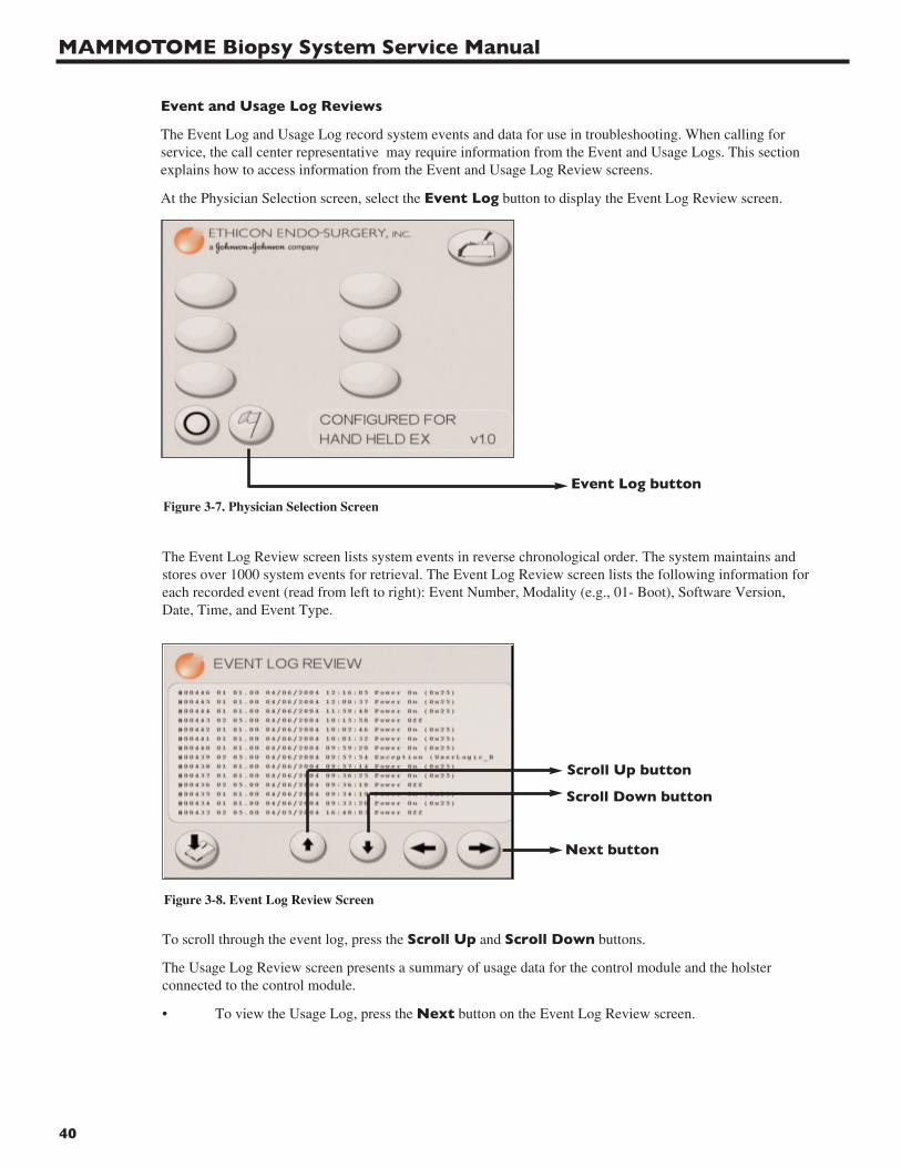
MAMMOTOME Biopsy System Service Manual
40
Event and Usage Log Reviews
The Event Log and Usage Log record system events and data for use in troubleshooting. When calling forservice, the call center representative may require information from the Event and Usage Logs. This sectionexplains how to access information from the Event and Usage Log Review screens.
At the Physician Selection screen, select the Event Log button to display the Event Log Review screen.
Event Log button
Scroll Up button
Scroll Down button
Next button
The Event Log Review screen lists system events in reverse chronological order. The system maintains andstores over 1000 system events for retrieval. The Event Log Review screen lists the following information foreach recorded event (read from left to right): Event Number, Modality (e.g., 01- Boot), Software Version,Date, Time, and Event Type.
To scroll through the event log, press the Scroll Up and Scroll Down buttons.
The Usage Log Review screen presents a summary of usage data for the control module and the holsterconnected to the control module.
• To view the Usage Log, press the Next button on the Event Log Review screen.
Figure 3-7. Physician Selection Screen
Figure 3-8. Event Log Review Screen
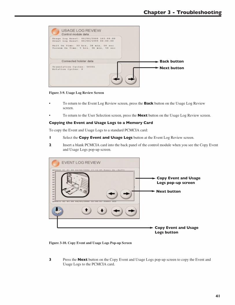
Chapter 3 - Troubleshooting
41
Back button
Next button
Copy Event and UsageLogs pop-up screen
Copy Event and UsageLogs button
Next button
• To return to the Event Log Review screen, press the Back button on the Usage Log Review screen.
• To return to the User Selection screen, press the Next button on the Usage Log Review screen.
Copying the Event and Usage Logs to a Memory Card
To copy the Event and Usage Logs to a standard PCMCIA card:
1 Select the Copy Event and Usage Logs button at the Event Log Review screen.
2 Insert a blank PCMCIA card into the back panel of the control module when you see the Copy Eventand Usage Logs pop-up screen.
3 Press the Next button on the Copy Event and Usage Logs pop-up screen to copy the Event and Usage Logs to the PCMCIA card.
Figure 3-9. Usage Log Review Screen
Figure 3-10. Copy Event and Usage Logs Pop-up Screen
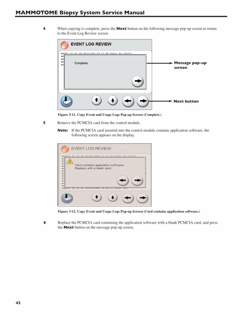
MAMMOTOME Biopsy System Service Manual
42
Message pop-upscreen
Next button
4 When copying is complete, press the Next button on the following message pop-up screen to return to the Event Log Review screen.
5 Remove the PCMCIA card from the control module.
Note: If the PCMCIA card inserted into the control module contains application software, the following screen appears on the display.
6 Replace the PCMCIA card containing the application software with a blank PCMCIA card, and pressthe Next button on the message pop-up screen.
Figure 3-11. Copy Event and Usage Logs Pop-up Screen (Complete.)
Figure 3-12. Copy Event and Usage Logs Pop-up Screen (Card contains application software.)
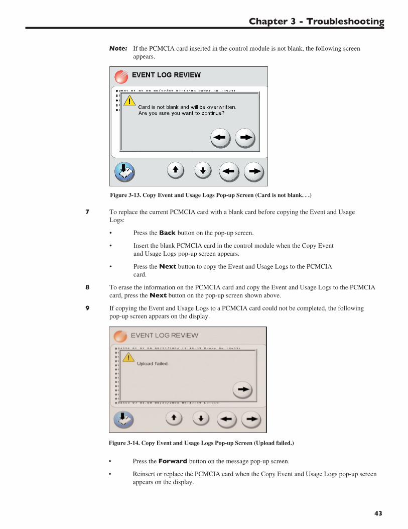
Chapter 3 - Troubleshooting
43
Note: If the PCMCIA card inserted in the control module is not blank, the following screen appears.
Figure 3-14. Copy Event and Usage Logs Pop-up Screen (Upload failed.)
Figure 3-13. Copy Event and Usage Logs Pop-up Screen (Card is not blank. . .)
7 To replace the current PCMCIA card with a blank card before copying the Event and Usage Logs:
• Press the Back button on the pop-up screen.
• Insert the blank PCMCIA card in the control module when the Copy Event and Usage Logs pop-up screen appears.
• Press the Next button to copy the Event and Usage Logs to the PCMCIA card.
8 To erase the information on the PCMCIA card and copy the Event and Usage Logs to the PCMCIA card, press the Next button on the pop-up screen shown above.
9 If copying the Event and Usage Logs to a PCMCIA card could not be completed, the following pop-up screen appears on the display.
• Press the Forward button on the message pop-up screen.
• Reinsert or replace the PCMCIA card when the Copy Event and Usage Logs pop-up screen appears on the display.
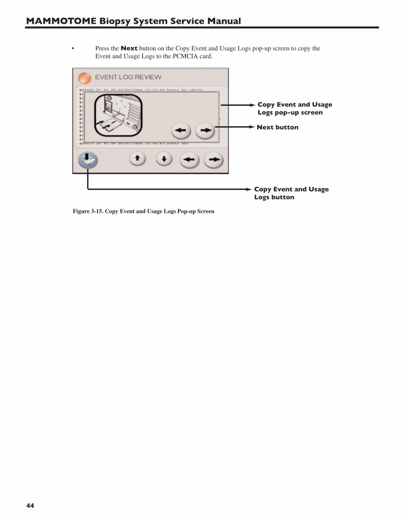
MAMMOTOME Biopsy System Service Manual
44
Copy Event and UsageLogs pop-up screen
Copy Event and UsageLogs button
Next button
• Press the Next button on the Copy Event and Usage Logs pop-up screen to copy the Event and Usage Logs to the PCMCIA card.
Figure 3-15. Copy Event and Usage Logs Pop-up Screen
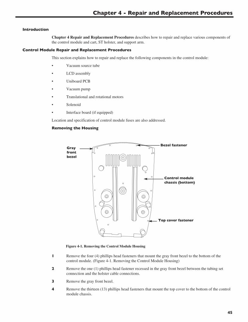
Chapter 4 - Repair and Replacement Procedures
45
Introduction
Chapter 4 Repair and Replacement Procedures describes how to repair and replace various components ofthe control module and cart, ST holster, and support arm.
Control Module Repair and Replacement Procedures
This section explains how to repair and replace the following components in the control module:
• Vacuum source tube
• LCD assembly
• Uniboard PCB
• Vacuum pump
• Translational and rotational motors
• Solenoid
• Interface board (if equipped)
Location and specification of control module fuses are also addressed.
Removing the Housing
1 Remove the four (4) phillips head fasteners that mount the gray front bezel to the bottom of thecontrol module. (Figure 4-1. Removing the Control Module Housing)
2 Remove the one (1) phillips head fastener recessed in the gray front bezel between the tubing setconnection and the holster cable connections.
3 Remove the gray front bezel.
4 Remove the thirteen (13) phillips head fasteners that mount the top cover to the bottom of the controlmodule chassis.
Figure 4-1. Removing the Control Module Housing
Control modulechassis (bottom)
Grayfrontbezel
Bezel fastener
Top cover fastener
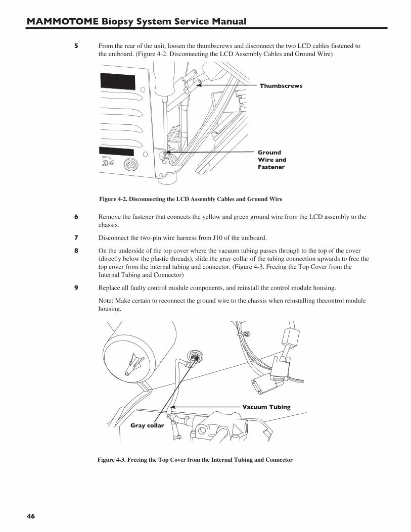
MAMMOTOME Biopsy System Service Manual
46
Vacuum Tubing
Figure 4-3. Freeing the Top Cover from the Internal Tubing and Connector
Gray collar
5 From the rear of the unit, loosen the thumbscrews and disconnect the two LCD cables fastened tothe uniboard. (Figure 4-2. Disconnecting the LCD Assembly Cables and Ground Wire)
6 Remove the fastener that connects the yellow and green ground wire from the LCD assembly to thechassis.
7 Disconnect the two-pin wire harness from J10 of the uniboard.
8 On the underside of the top cover where the vacuum tubing passes through to the top of the cover(directly below the plastic threads), slide the gray collar of the tubing connection upwards to free thetop cover from the internal tubing and connector. (Figure 4-3. Freeing the Top Cover from theInternal Tubing and Connector)
9 Replace all faulty control module components, and reinstall the control module housing.
Note: Make certain to reconnect the ground wire to the chassis when reinstalling thecontrol modulehousing.
Thumbscrews
GroundWire andFastener
Figure 4-2. Disconnecting the LCD Assembly Cables and Ground Wire
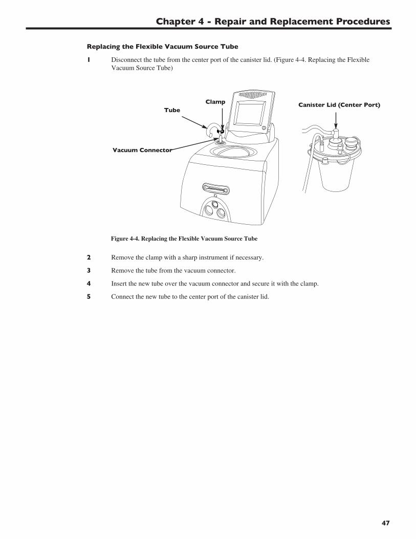
Chapter 4 - Repair and Replacement Procedures
47
Replacing the Flexible Vacuum Source Tube
1 Disconnect the tube from the center port of the canister lid. (Figure 4-4. Replacing the Flexible Vacuum Source Tube)
2 Remove the clamp with a sharp instrument if necessary.
3 Remove the tube from the vacuum connector.
4 Insert the new tube over the vacuum connector and secure it with the clamp.
5 Connect the new tube to the center port of the canister lid.
ClampTube
Vacuum Connector
Canister Lid (Center Port)
Figure 4-4. Replacing the Flexible Vacuum Source Tube
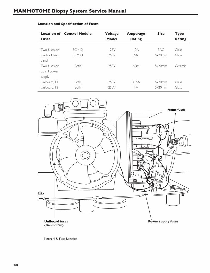
MAMMOTOME Biopsy System Service Manual
48
Location and Specification of Fuses
Location of Control Module Voltage Amperage Size Type
Fuses Model Rating Rating
Two fuses on SCM12 125V 10A 3AG Glass
inside of back SCM23 250V 5A 5x20mm Glass
panel
Two fuses on Both 250V 6.3A 5x20mm Ceramic
board power
supply
Uniboard, F1 Both 250V 3.15A 5x20mm Glass
Uniboard, F2 Both 250V 1A 5x20mm Glass
Uniboard fuses(Behind fan)
Mains fuses
Power supply fuses
Figure 4-5. Fuse Location
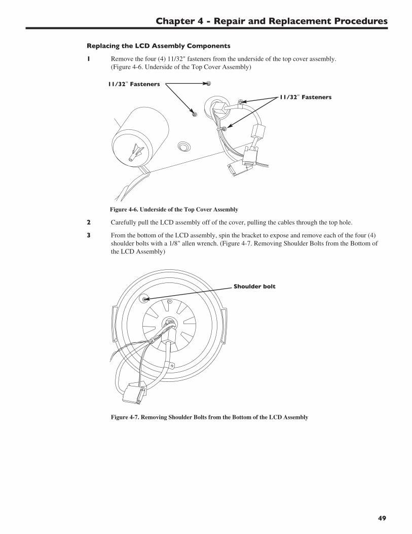
Chapter 4 - Repair and Replacement Procedures
49
Replacing the LCD Assembly Components
1 Remove the four (4) 11/32" fasteners from the underside of the top cover assembly.(Figure 4-6. Underside of the Top Cover Assembly)
2 Carefully pull the LCD assembly off of the cover, pulling the cables through the top hole.
3 From the bottom of the LCD assembly, spin the bracket to expose and remove each of the four (4)shoulder bolts with a 1/8" allen wrench. (Figure 4-7. Removing Shoulder Bolts from the Bottom ofthe LCD Assembly)
11/32" Fasteners
11/32" Fasteners
Shoulder bolt
Figure 4-6. Underside of the Top Cover Assembly
Figure 4-7. Removing Shoulder Bolts from the Bottom of the LCD Assembly
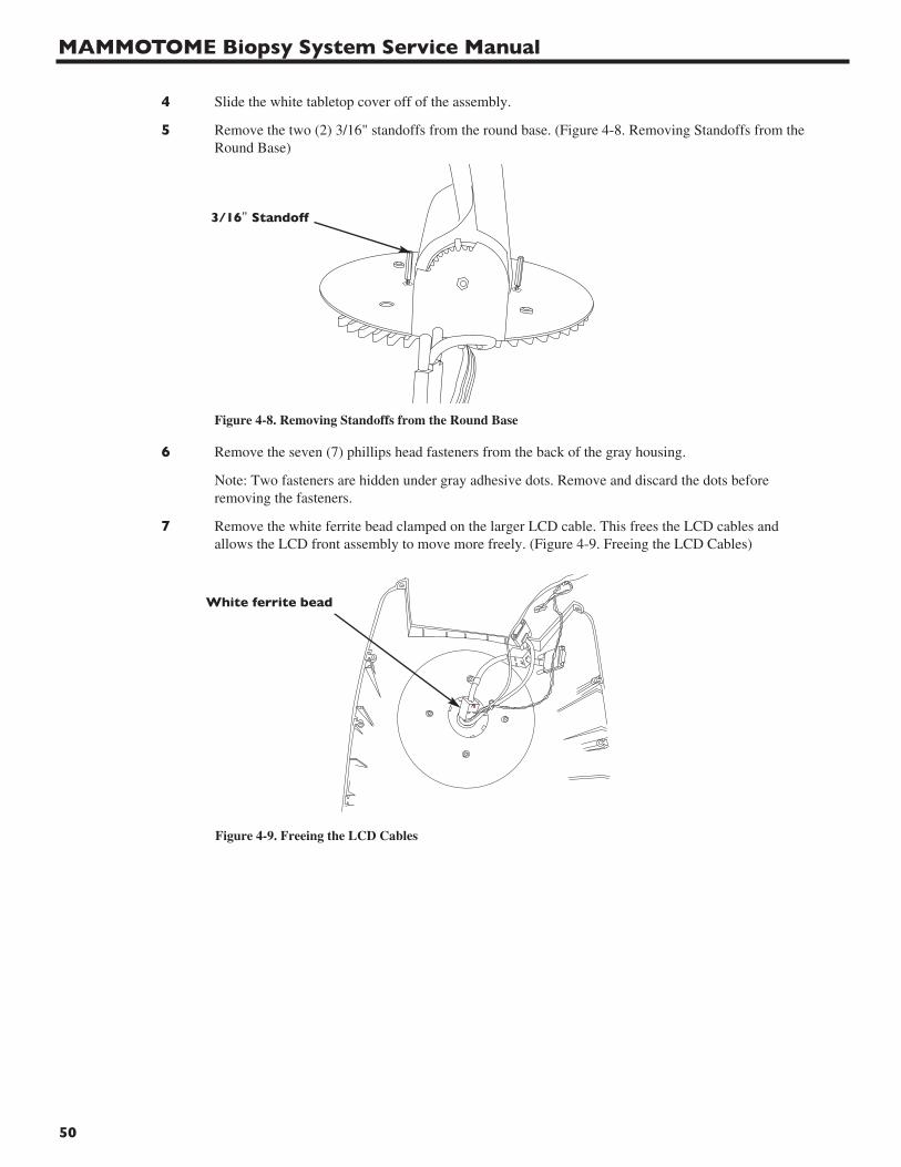
MAMMOTOME Biopsy System Service Manual
50
4 Slide the white tabletop cover off of the assembly.
5 Remove the two (2) 3/16" standoffs from the round base. (Figure 4-8. Removing Standoffs from theRound Base)
6 Remove the seven (7) phillips head fasteners from the back of the gray housing.
Note: Two fasteners are hidden under gray adhesive dots. Remove and discard the dots beforeremoving the fasteners.
7 Remove the white ferrite bead clamped on the larger LCD cable. This frees the LCD cables andallows the LCD front assembly to move more freely. (Figure 4-9. Freeing the LCD Cables)
3/16" Standoff
White ferrite bead
Figure 4-8. Removing Standoffs from the Round Base
Figure 4-9. Freeing the LCD Cables
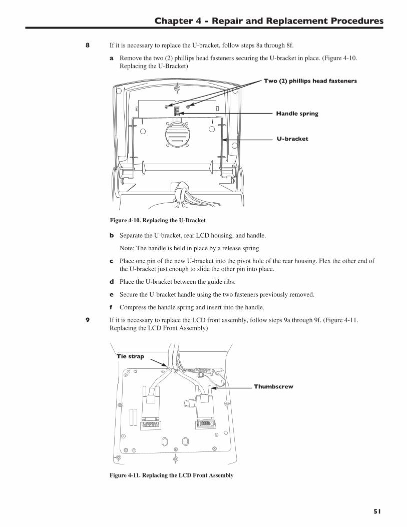
Chapter 4 - Repair and Replacement Procedures
51
8 If it is necessary to replace the U-bracket, follow steps 8a through 8f.
a Remove the two (2) phillips head fasteners securing the U-bracket in place. (Figure 4-10. Replacing the U-Bracket)
b Separate the U-bracket, rear LCD housing, and handle.
Note: The handle is held in place by a release spring.
c Place one pin of the new U-bracket into the pivot hole of the rear housing. Flex the other end of the U-bracket just enough to slide the other pin into place.
d Place the U-bracket between the guide ribs.
e Secure the U-bracket handle using the two fasteners previously removed.
f Compress the handle spring and insert into the handle.
9 If it is necessary to replace the LCD front assembly, follow steps 9a through 9f. (Figure 4-11.Replacing the LCD Front Assembly)
Two (2) phillips head fasteners
Tie strap
Thumbscrew
Handle spring
Figure 4-10. Replacing the U-Bracket
Figure 4-11. Replacing the LCD Front Assembly
U-bracket

MAMMOTOME Biopsy System Service Manual
52
a Loosen the thumbscrews and disconnect the two LCD cables from the PCB.
b Remove the fastener and star washer securing the ground cable.
c Cut the two tie straps securing the LCD cables.
Caution: Do Not cut the cable jacket.
d Remove the cables.
e Secure the LCD cables to the new LCD front assembly with two new tie straps.
f Remount the ground wire.
g Reinstall the LCD cables so that the thicker cable is at J1 of the PCB and the thin cable is at J6.
h Tighten the thumbscrews.
10 Make sure that the speaker is properly mounted, and the speaker wires pass through the wire holderor channel on the rear housing of the LCD.
11 Gently press the two halves together, pulling excess wires through as they come together. Make surethat the rubber tube does not pinch between the halves.
12 Secure with the seven (7) phillips head fasteners previously removed.
13 Clean the areas around the two fasteners flanking the speaker grille. Cover the fasteners with newadhesive dots.
14 Reconnect the ferrite bead to the thick LCD cable near the opening of the rubber resistance fingers.
15 Reinstall the two 3/16" standoffs.
16 Place the tabletop over the LCD assembly, with the beveled tabletop surface in front of the LCD.
17 Turn the assembly over and place the turntable on the rubber surface so that the four (4) fastenersextend from the turntable.
18 Spin the turntable to expose one of the four (4) mounting holes.
19 Thread one of the shoulder bolts into the exposed mounting hole until the bolt clears the top of theturntable, but Do Not tighten completely.
20 Install the remaining three shoulder bolts, and completely tighten all four.
21 Pass the LCD cables, speaker cable, and ground wire through the top cover housing.
22 Align the four (4) fasteners in the turntable with the top cover.
23 Firmly press the LCD assembly in place so that it rests flush with the top cover.
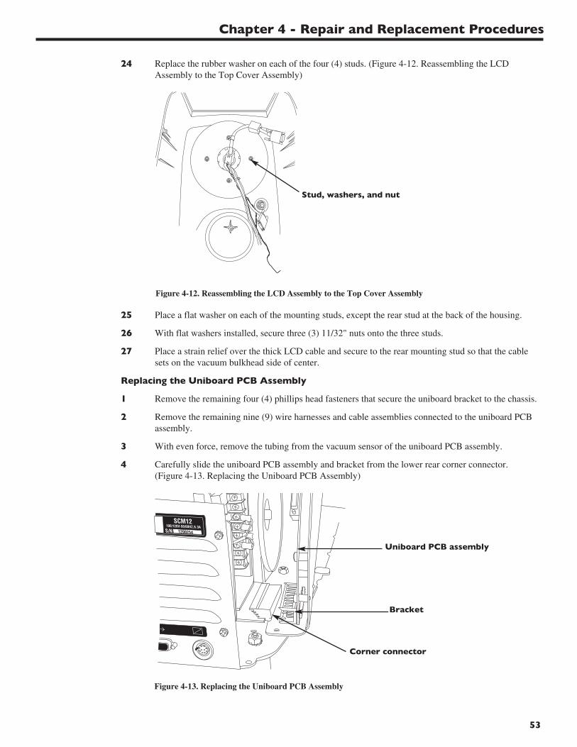
Chapter 4 - Repair and Replacement Procedures
53
24 Replace the rubber washer on each of the four (4) studs. (Figure 4-12. Reassembling the LCDAssembly to the Top Cover Assembly)
25 Place a flat washer on each of the mounting studs, except the rear stud at the back of the housing.
26 With flat washers installed, secure three (3) 11/32" nuts onto the three studs.
27 Place a strain relief over the thick LCD cable and secure to the rear mounting stud so that the cablesets on the vacuum bulkhead side of center.
Replacing the Uniboard PCB Assembly
1 Remove the remaining four (4) phillips head fasteners that secure the uniboard bracket to the chassis.
2 Remove the remaining nine (9) wire harnesses and cable assemblies connected to the uniboard PCBassembly.
3 With even force, remove the tubing from the vacuum sensor of the uniboard PCB assembly.
4 Carefully slide the uniboard PCB assembly and bracket from the lower rear corner connector.(Figure 4-13. Replacing the Uniboard PCB Assembly)
Uniboard PCB assembly
Bracket
Corner connector
Figure 4-13. Replacing the Uniboard PCB Assembly
Stud, washers, and nut
Figure 4-12. Reassembling the LCD Assembly to the Top Cover Assembly

MAMMOTOME Biopsy System Service Manual
54
5 Remove the eight (8) phillips head fasteners that secure the uniboard to the bracket.
6 Replace the uniboard PCB assembly, and secure it to the bracket with the eight (8) fasteners.
7 At the lower rear corner of the uniboard PCB assembly, carefully connect the assembly to theconnector PCB.
8 Reconnect all wire harnesses.
9 Reattach the vacuum tubing to the bottom fitting of the vacuum sensor.
Caution: Apply force in a straight, even motion; moving the tubing back and forth onto the sensormay cause the fitting to break.
10 Secure the bracket to the chassis with the four (4) fasteners.
Note: Do Not replace the rearmost fastener; this location will be required to fasten the ground wirefrom the LCD assembly when the top cover is replaced.
Replacing the Interface Board Assembly
1 Remove the two (2) wiring harnesses and one (1) power cable connector from the Interface board.
2 Remove the remaining two (2) phillips head fasteners that secure the interface board bracket to thecapacitor and front interface bracket assemblies.
3 Remove the phillips head fasteners that secure the interface board to the bracket.
4 Replace the interface board and secure it to the bracket.
5 Reconnect all wiring harnesses.
6 Secure the bracket to the chassis with the two (2) fasteners.
Replacing the Vacuum Pump
1 Carefully remove the tie strap securing the tubing to the intake valve of the defective vacuum pump.(Figure 4-14. Replacing the Vacuum Pump)
Note: Do Not cut or damage the tubing.
2 Remove the tubing from the valve.
3 Remove the intake valve from the pump and retain for reassembling to the new vacuum pump.
4 Remove the muffler and brass fittings from the exhaust of the defective vacuum pump.
Figure 4-14. Replacing the Vacuum Pump
ValveTie strap
Tubing
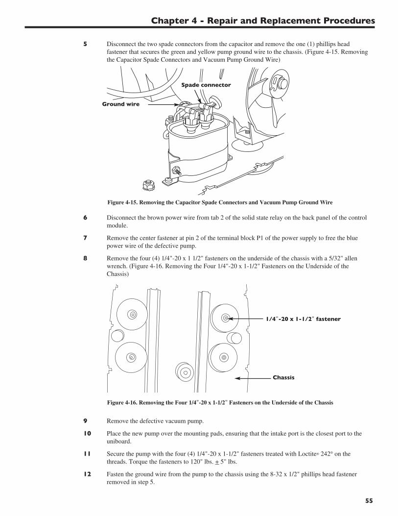
Chapter 4 - Repair and Replacement Procedures
55
5 Disconnect the two spade connectors from the capacitor and remove the one (1) phillips headfastener that secures the green and yellow pump ground wire to the chassis. (Figure 4-15. Removingthe Capacitor Spade Connectors and Vacuum Pump Ground Wire)
6 Disconnect the brown power wire from tab 2 of the solid state relay on the back panel of the controlmodule.
7 Remove the center fastener at pin 2 of the terminal block P1 of the power supply to free the bluepower wire of the defective pump.
8 Remove the four (4) 1/4"-20 x 1 1/2" fasteners on the underside of the chassis with a 5/32" allenwrench. (Figure 4-16. Removing the Four 1/4"-20 x 1-1/2" Fasteners on the Underside of theChassis)
9 Remove the defective vacuum pump.
10 Place the new pump over the mounting pads, ensuring that the intake port is the closest port to theuniboard.
11 Secure the pump with the four (4) 1/4"-20 x 1-1/2" fasteners treated with Loctite® 242® on thethreads. Torque the fasteners to 120" lbs. + 5" lbs.
12 Fasten the ground wire from the pump to the chassis using the 8-32 x 1/2" phillips head fastenerremoved in step 5.
Ground wire
Spade connector
1/4"-20 x 1-1/2" fastener
Figure 4-15. Removing the Capacitor Spade Connectors and Vacuum Pump Ground Wire
Figure 4-16. Removing the Four 1/4"-20 x 1-1/2" Fasteners on the Underside of the Chassis
Chassis
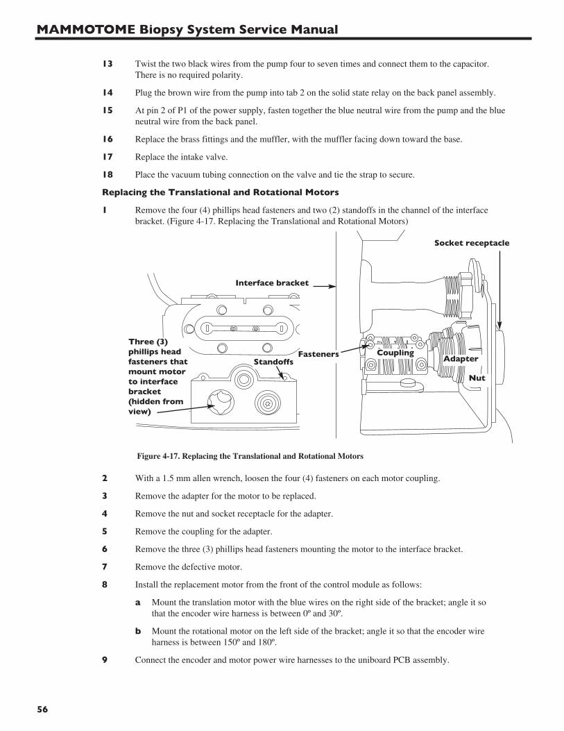
MAMMOTOME Biopsy System Service Manual
56
13 Twist the two black wires from the pump four to seven times and connect them to the capacitor.There is no required polarity.
14 Plug the brown wire from the pump into tab 2 on the solid state relay on the back panel assembly.
15 At pin 2 of P1 of the power supply, fasten together the blue neutral wire from the pump and the blueneutral wire from the back panel.
16 Replace the brass fittings and the muffler, with the muffler facing down toward the base.
17 Replace the intake valve.
18 Place the vacuum tubing connection on the valve and tie the strap to secure.
Replacing the Translational and Rotational Motors
1 Remove the four (4) phillips head fasteners and two (2) standoffs in the channel of the interfacebracket. (Figure 4-17. Replacing the Translational and Rotational Motors)
2 With a 1.5 mm allen wrench, loosen the four (4) fasteners on each motor coupling.
3 Remove the adapter for the motor to be replaced.
4 Remove the nut and socket receptacle for the adapter.
5 Remove the coupling for the adapter.
6 Remove the three (3) phillips head fasteners mounting the motor to the interface bracket.
7 Remove the defective motor.
8 Install the replacement motor from the front of the control module as follows:
a Mount the translation motor with the blue wires on the right side of the bracket; angle it so that the encoder wire harness is between 0º and 30º.
b Mount the rotational motor on the left side of the bracket; angle it so that the encoder wire harness is between 150º and 180º.
9 Connect the encoder and motor power wire harnesses to the uniboard PCB assembly.
Interface bracket
CouplingThree (3)phillips headfasteners thatmount motorto interfacebracket(hidden fromview)
AdapterStandoffs
Socket receptacle
Nut
Fasteners
Figure 4-17. Replacing the Translational and Rotational Motors
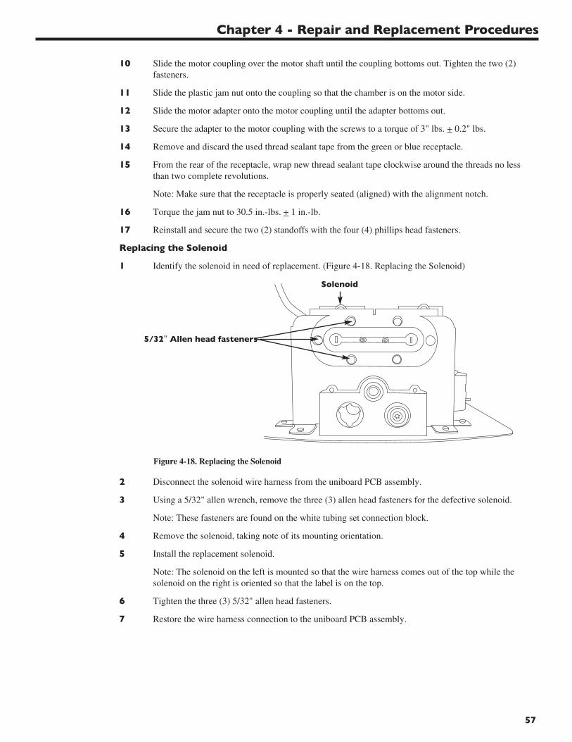
Chapter 4 - Repair and Replacement Procedures
57
10 Slide the motor coupling over the motor shaft until the coupling bottoms out. Tighten the two (2)fasteners.
11 Slide the plastic jam nut onto the coupling so that the chamber is on the motor side.
12 Slide the motor adapter onto the motor coupling until the adapter bottoms out.
13 Secure the adapter to the motor coupling with the screws to a torque of 3" lbs. + 0.2" lbs.
14 Remove and discard the used thread sealant tape from the green or blue receptacle.
15 From the rear of the receptacle, wrap new thread sealant tape clockwise around the threads no lessthan two complete revolutions.
Note: Make sure that the receptacle is properly seated (aligned) with the alignment notch.
16 Torque the jam nut to 30.5 in.-lbs. + 1 in.-lb.
17 Reinstall and secure the two (2) standoffs with the four (4) phillips head fasteners.
Replacing the Solenoid
1 Identify the solenoid in need of replacement. (Figure 4-18. Replacing the Solenoid)
2 Disconnect the solenoid wire harness from the uniboard PCB assembly.
3 Using a 5/32" allen wrench, remove the three (3) allen head fasteners for the defective solenoid.
Note: These fasteners are found on the white tubing set connection block.
4 Remove the solenoid, taking note of its mounting orientation.
5 Install the replacement solenoid.
Note: The solenoid on the left is mounted so that the wire harness comes out of the top while thesolenoid on the right is oriented so that the label is on the top.
6 Tighten the three (3) 5/32" allen head fasteners.
7 Restore the wire harness connection to the uniboard PCB assembly.
Solenoid
5/32" Allen head fasteners
Figure 4-18. Replacing the Solenoid
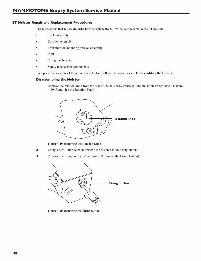
MAMMOTOME Biopsy System Service Manual
58
ST Holster Repair and Replacement Procedures
The instructions that follow describe how to replace the following components in the ST holster:
• Cable assembly
• Encoder assembly
• Transmission mounting bracket assembly
• PCB
• Firing mechanism
• Safety mechanism components
To replace one or more of these components, first follow the instructions in Disassembling the Holster.
Disassembling the Holster
1 Remove the rotation knob from the rear of the holster by gently pulling the knob straight back. (Figure4-19. Removing the Rotation Knob)
2 Using a 5/64" allen wrench, remove the fastener in the firing button.
3 Remove the firing button. (Figure 4-20. Removing the Firing Button)
Rotation knob
Figure 4-19. Removing the Rotation Knob
Figure 4-20. Removing the Firing Button
Firing button
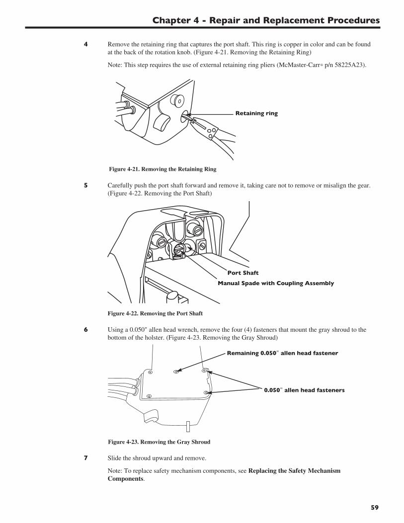
Chapter 4 - Repair and Replacement Procedures
59
4 Remove the retaining ring that captures the port shaft. This ring is copper in color and can be foundat the back of the rotation knob. (Figure 4-21. Removing the Retaining Ring)
Note: This step requires the use of external retaining ring pliers (McMaster-Carr® p/n 58225A23).
5 Carefully push the port shaft forward and remove it, taking care not to remove or misalign the gear.(Figure 4-22. Removing the Port Shaft)
6 Using a 0.050" allen head wrench, remove the four (4) fasteners that mount the gray shroud to thebottom of the holster. (Figure 4-23. Removing the Gray Shroud)
7 Slide the shroud upward and remove.
Note: To replace safety mechanism components, see Replacing the Safety Mechanism Components.
0.050" allen head fasteners
Remaining 0.050" allen head fastener
Figure 4-22. Removing the Port Shaft
Figure 4-21. Removing the Retaining Ring
Retaining ring
Figure 4-23. Removing the Gray Shroud
Manual Spade with Coupling Assembly
Port Shaft
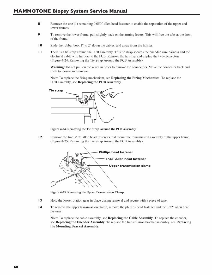
MAMMOTOME Biopsy System Service Manual
60
8 Remove the one (1) remaining 0.050" allen head fastener to enable the separation of the upper andlower frames.
9 To remove the lower frame, pull slightly back on the arming levers. This will free the tabs at the front of the frame.
10 Slide the rubber boot 1" to 2" down the cables, and away from the holster.
11 There is a tie strap around the PCB assembly. This tie strap secures the encoder wire harness and theelectrical cable wire harness to the PCB. Remove the tie strap and unplug the two connectors.(Figure 4-24. Removing the Tie Strap Around the PCB Assembly)
Warning: Do not pull on the wires in order to remove the connectors. Move the connector back and forth to loosen and remove.
Note: To replace the firing mechanism, see Replacing the Firing Mechanism. To replace the PCB assembly, see Replacing the PCB Assembly.
12 Remove the two 3/32" allen head fasteners that mount the transmission assembly to the upper frame.(Figure 4-25. Removing the Tie Strap Around the PCB Assembly)
13 Hold the loose rotation gear in place during removal and secure with a piece of tape.
14 To remove the upper transmission clamp, remove the phillips head fastener and the 3/32" allen headfastener.
Note: To replace the cable assembly, see Replacing the Cable Assembly. To replace the encoder, see Replacing the Encoder Assembly. To replace the transmission bracket assembly, see Replacing the Mounting Bracket Assembly.
Tie strap
Figure 4-24. Removing the Tie Strap Around the PCB Assembly
Phillips head fastener
3/32" Allen head fastener
Upper transmission clamp
Figure 4-25. Removing the Upper Transmission Clamp
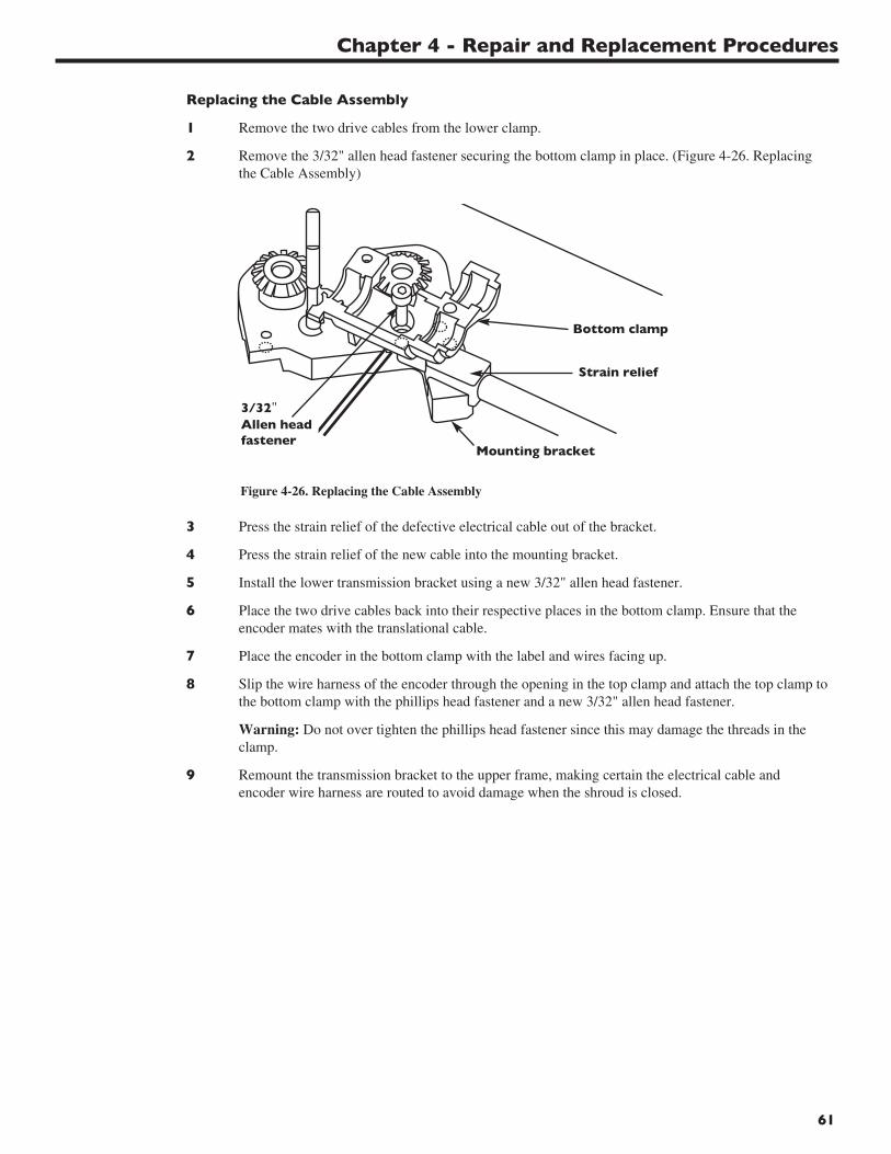
Chapter 4 - Repair and Replacement Procedures
61
Replacing the Cable Assembly
1 Remove the two drive cables from the lower clamp.
2 Remove the 3/32" allen head fastener securing the bottom clamp in place. (Figure 4-26. Replacingthe Cable Assembly)
3 Press the strain relief of the defective electrical cable out of the bracket.
4 Press the strain relief of the new cable into the mounting bracket.
5 Install the lower transmission bracket using a new 3/32" allen head fastener.
6 Place the two drive cables back into their respective places in the bottom clamp. Ensure that theencoder mates with the translational cable.
7 Place the encoder in the bottom clamp with the label and wires facing up.
8 Slip the wire harness of the encoder through the opening in the top clamp and attach the top clamp tothe bottom clamp with the phillips head fastener and a new 3/32" allen head fastener.
Warning: Do not over tighten the phillips head fastener since this may damage the threads in the clamp.
9 Remount the transmission bracket to the upper frame, making certain the electrical cable andencoder wire harness are routed to avoid damage when the shroud is closed.
3/32"Allen headfastener
Bottom clamp
Strain relief
Mounting bracket
Figure 4-26. Replacing the Cable Assembly
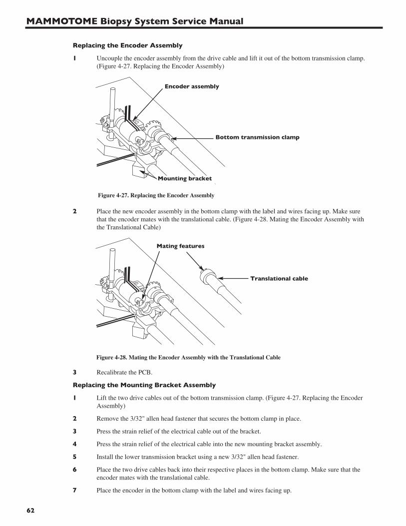
MAMMOTOME Biopsy System Service Manual
62
Replacing the Encoder Assembly
1 Uncouple the encoder assembly from the drive cable and lift it out of the bottom transmission clamp.(Figure 4-27. Replacing the Encoder Assembly)
2 Place the new encoder assembly in the bottom clamp with the label and wires facing up. Make surethat the encoder mates with the translational cable. (Figure 4-28. Mating the Encoder Assembly withthe Translational Cable)
3 Recalibrate the PCB.
Replacing the Mounting Bracket Assembly
1 Lift the two drive cables out of the bottom transmission clamp. (Figure 4-27. Replacing the EncoderAssembly)
2 Remove the 3/32" allen head fastener that secures the bottom clamp in place.
3 Press the strain relief of the electrical cable out of the bracket.
4 Press the strain relief of the electrical cable into the new mounting bracket assembly.
5 Install the lower transmission bracket using a new 3/32" allen head fastener.
6 Place the two drive cables back into their respective places in the bottom clamp. Make sure that theencoder mates with the translational cable.
7 Place the encoder in the bottom clamp with the label and wires facing up.
Figure 4-27. Replacing the Encoder Assembly
Bottom transmission clamp
Encoder assembly
Mounting bracket
Figure 4-28. Mating the Encoder Assembly with the Translational Cable
Mating features
Translational cable
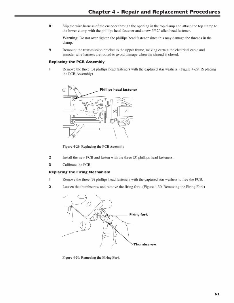
Chapter 4 - Repair and Replacement Procedures
63
8 Slip the wire harness of the encoder through the opening in the top clamp and attach the top clamp tothe lower clamp with the phillips head fastener and a new 3/32" allen head fastener.
Warning: Do not over tighten the phillips head fastener since this may damage the threads in the clamp.
9 Remount the transmission bracket to the upper frame, making certain the electrical cable andencoder wire harness are routed to avoid damage when the shroud is closed.
Replacing the PCB Assembly
1 Remove the three (3) phillips head fasteners with the captured star washers. (Figure 4-29. Replacingthe PCB Assembly)
2 Install the new PCB and fasten with the three (3) phillips head fasteners.
3 Calibrate the PCB.
Replacing the Firing Mechanism
1 Remove the three (3) phillips head fasteners with the captured star washers to free the PCB.
2 Loosen the thumbscrew and remove the firing fork. (Figure 4-30. Removing the Firing Fork)
Firing fork
Thumbscrew
Figure 4-30. Removing the Firing Fork
Figure 4-29. Replacing the PCB Assembly
Phillips head fastener
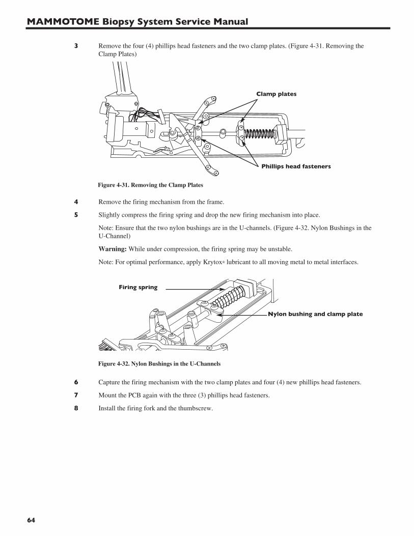
MAMMOTOME Biopsy System Service Manual
64
3 Remove the four (4) phillips head fasteners and the two clamp plates. (Figure 4-31. Removing theClamp Plates)
4 Remove the firing mechanism from the frame.
5 Slightly compress the firing spring and drop the new firing mechanism into place.
Note: Ensure that the two nylon bushings are in the U-channels. (Figure 4-32. Nylon Bushings in theU-Channel)
Warning: While under compression, the firing spring may be unstable.
Note: For optimal performance, apply Krytox® lubricant to all moving metal to metal interfaces.
6 Capture the firing mechanism with the two clamp plates and four (4) new phillips head fasteners.
7 Mount the PCB again with the three (3) phillips head fasteners.
8 Install the firing fork and the thumbscrew.
Clamp plates
Phillips head fasteners
Figure 4-31. Removing the Clamp Plates
Figure 4-32. Nylon Bushings in the U-Channels
Nylon bushing and clamp plate
Firing spring
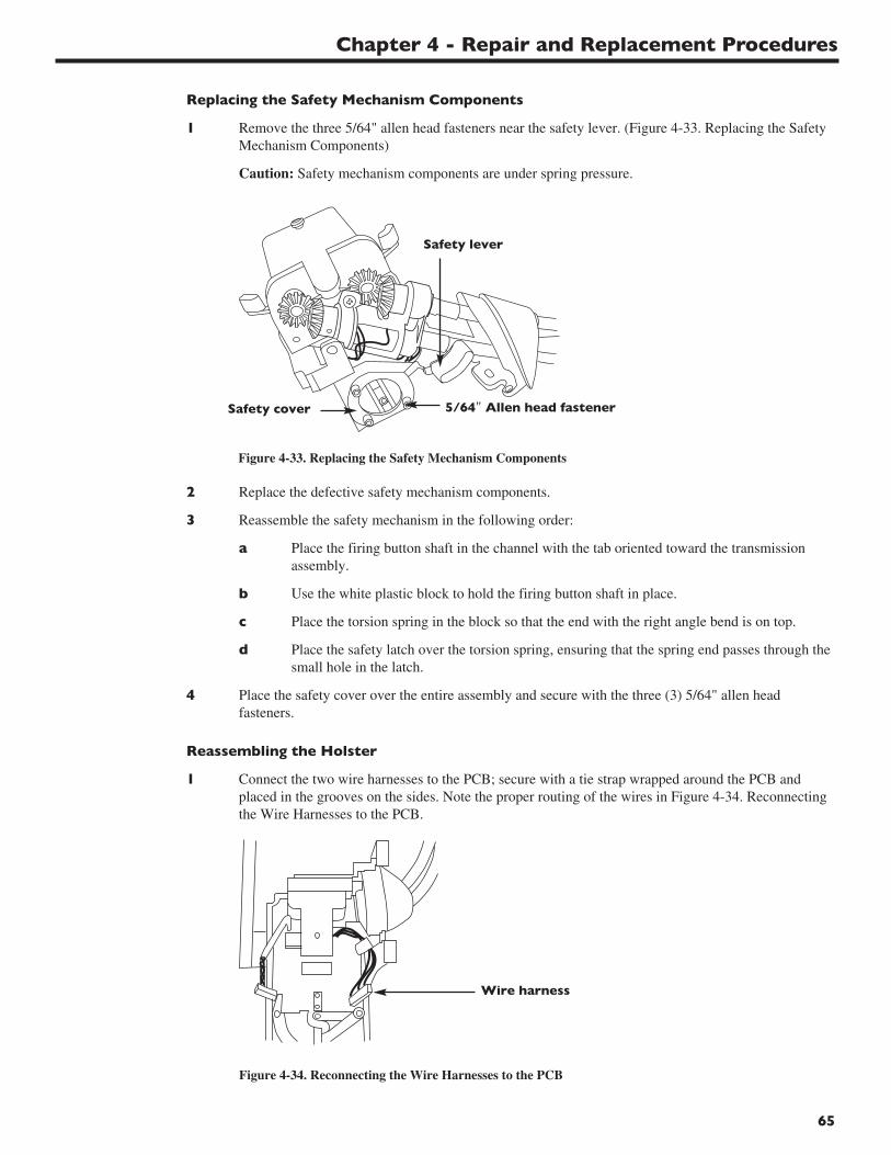
Chapter 4 - Repair and Replacement Procedures
65
Replacing the Safety Mechanism Components
1 Remove the three 5/64" allen head fasteners near the safety lever. (Figure 4-33. Replacing the Safety Mechanism Components)
Caution: Safety mechanism components are under spring pressure.
2 Replace the defective safety mechanism components.
3 Reassemble the safety mechanism in the following order:
a Place the firing button shaft in the channel with the tab oriented toward the transmission assembly.
b Use the white plastic block to hold the firing button shaft in place.
c Place the torsion spring in the block so that the end with the right angle bend is on top.
d Place the safety latch over the torsion spring, ensuring that the spring end passes through the small hole in the latch.
4 Place the safety cover over the entire assembly and secure with the three (3) 5/64" allen head fasteners.
Reassembling the Holster
1 Connect the two wire harnesses to the PCB; secure with a tie strap wrapped around the PCB andplaced in the grooves on the sides. Note the proper routing of the wires in Figure 4-34. Reconnecting the Wire Harnesses to the PCB.
Figure 4-34. Reconnecting the Wire Harnesses to the PCB
Wire harness
Figure 4-33. Replacing the Safety Mechanism Components
Safety cover 5/64" Allen head fastener
Safety lever

MAMMOTOME Biopsy System Service Manual
66
2 Slide the rubber boot back towards the transmission assembly.
3 Reattach the lower frame by inserting the tabs into the upper frame and pivoting the back of the frame into place. Pull slightly back on the cocking levers as you insert the tabs.
4 Replace the 0.050" allen head fastener attaching the upper and lower frame.
5 Slide the shroud over the holster and fasten with the four 0.050" allen head fasteners.
6 Push the port shaft into the spur gear.
Note: Make sure that when the flat of the port shaft is facing up, the rotation spade on the other side ofthe assembly is horizontal.
7 Replace the retaining ring on the port shaft.
8 Install the firing button and the allen head fastener.
9 Using the flat surface of the port shaft as a guide, push the rotation knob into place.
EX Holster Repair and Replacement Procedures
The instructions that follow describe how to replace the following components in the EX Holster:
• Power cord assembly
• Bottom housing
• Top housing
• Keypad cover
• Flex circuit assembly
• Front DC motor (rotation)
• Rotation motor extension shaft
• Rotation motor drive shaft
• Rear DC motor (translation) and gear
• Drive shafts, bushings, chains, and gears
Note: All fasteners must have a pre-applied bead of Loctite and be tightened with a torque driver to 2.0 +/- .5 in-lbs.
Replacing the Power Cord Assembly
1 Remove the two (2) phillips head fasteners from the power cable mount and slide the assembly straight back to remove.
2 Inspect seal on bottom housing. If seal is broken or damaged, replace the housing.
3 To replace, slide the assembly back into the jack and push forward, insert the two (2) phillips head fasteners, and tighten.
Replacing the Bottom Housing
1 Remove the power cable assembly.
2 Remove the phillips head fastener from the rear of the housing.
3 Holding the bottom housing at the rear, pull the housing up and rotate toward the front of the holster, taking care not to break the locking tabs on the front of the housing. (Figure 4-35. Replacing the Bottom Housing)
4 Inspect seals on bottom housing. If seal is broken or damaged replace the housing.
5 To replace the bottom housing, reverse the above procedure.
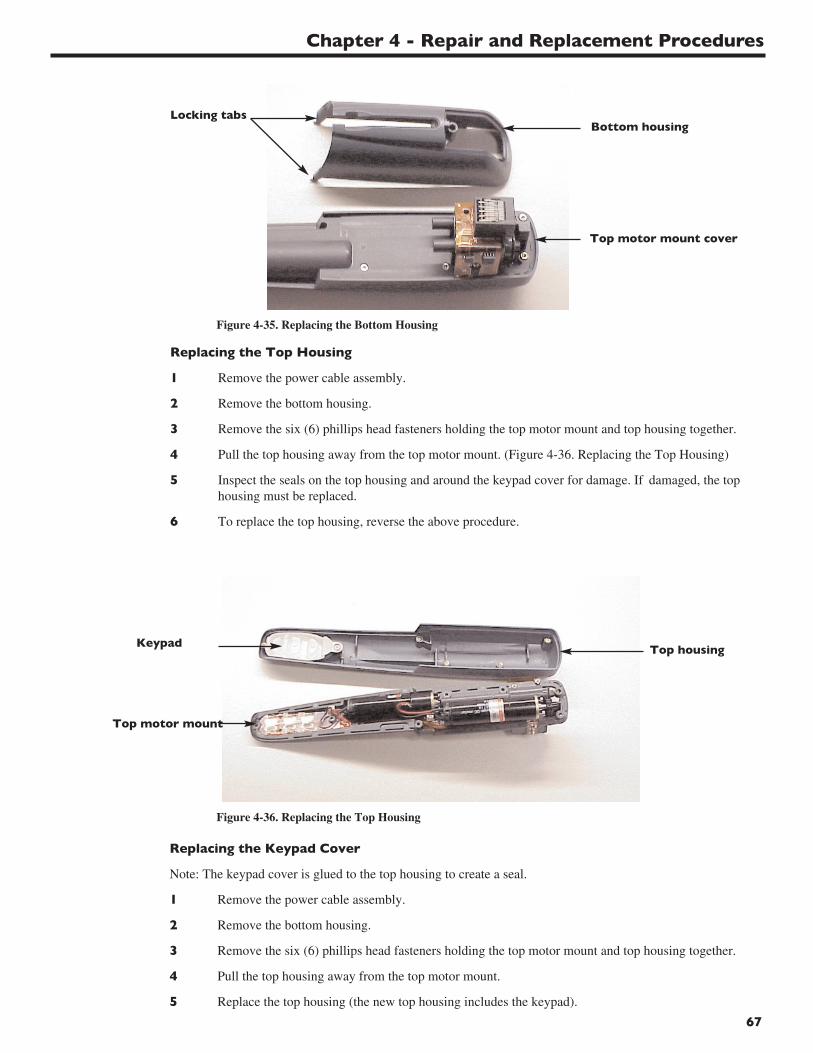
Chapter 4 - Repair and Replacement Procedures
67
Figure 4-36. Replacing the Top Housing
Top housing
Top motor mount
Keypad
Figure 4-35. Replacing the Bottom Housing
Bottom housing
Top motor mount cover
Locking tabs
Replacing the Top Housing
1 Remove the power cable assembly.
2 Remove the bottom housing.
3 Remove the six (6) phillips head fasteners holding the top motor mount and top housing together.
4 Pull the top housing away from the top motor mount. (Figure 4-36. Replacing the Top Housing)
5 Inspect the seals on the top housing and around the keypad cover for damage. If damaged, the top housing must be replaced.
6 To replace the top housing, reverse the above procedure.
Replacing the Keypad Cover
Note: The keypad cover is glued to the top housing to create a seal.
1 Remove the power cable assembly.
2 Remove the bottom housing.
3 Remove the six (6) phillips head fasteners holding the top motor mount and top housing together.
4 Pull the top housing away from the top motor mount.
5 Replace the top housing (the new top housing includes the keypad).
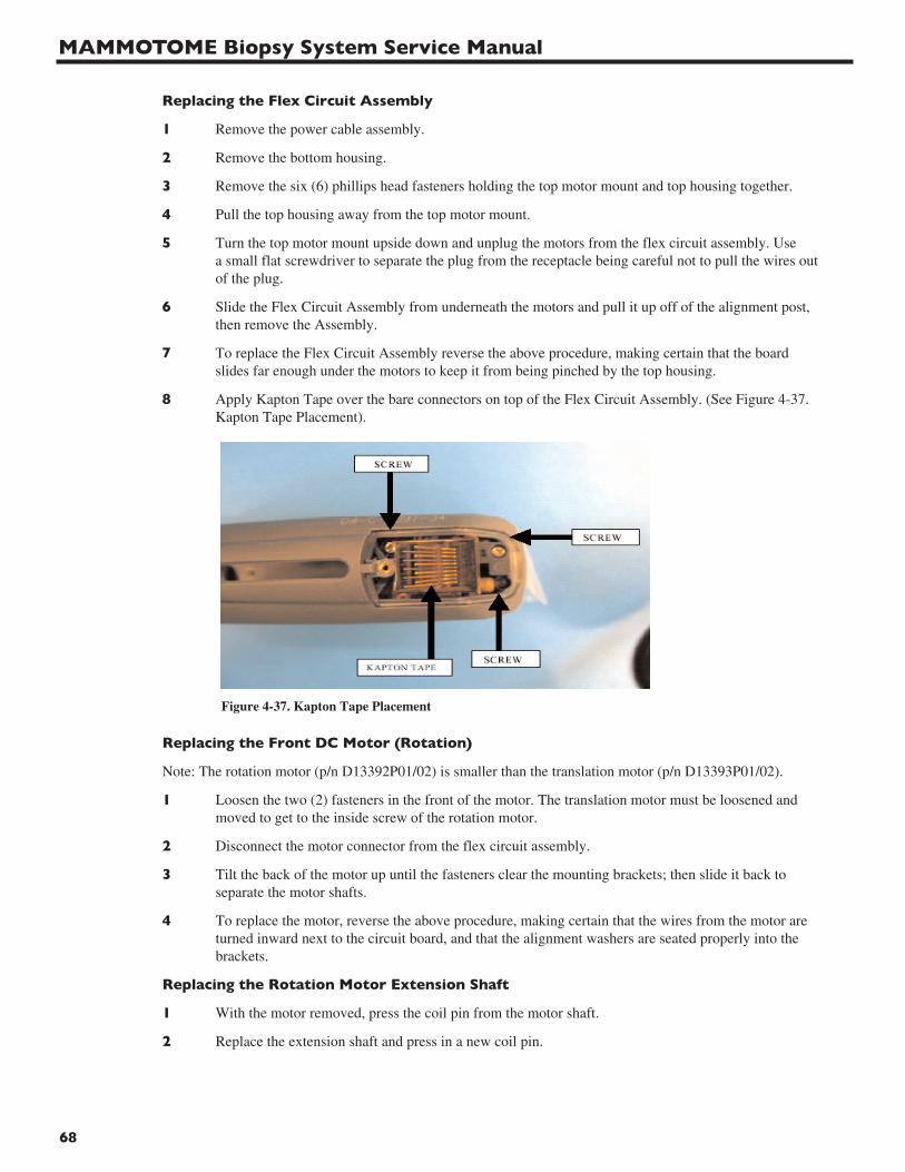
MAMMOTOME Biopsy System Service Manual
68
Replacing the Flex Circuit Assembly
1 Remove the power cable assembly.
2 Remove the bottom housing.
3 Remove the six (6) phillips head fasteners holding the top motor mount and top housing together.
4 Pull the top housing away from the top motor mount.
5 Turn the top motor mount upside down and unplug the motors from the flex circuit assembly. Use a small flat screwdriver to separate the plug from the receptacle being careful not to pull the wires out of the plug.
6 Slide the Flex Circuit Assembly from underneath the motors and pull it up off of the alignment post, then remove the Assembly.
7 To replace the Flex Circuit Assembly reverse the above procedure, making certain that the board slides far enough under the motors to keep it from being pinched by the top housing.
8 Apply Kapton Tape over the bare connectors on top of the Flex Circuit Assembly. (See Figure 4-37. Kapton Tape Placement).
Figure 4-37. Kapton Tape Placement
Replacing the Front DC Motor (Rotation)
Note: The rotation motor (p/n D13392P01/02) is smaller than the translation motor (p/n D13393P01/02).
1 Loosen the two (2) fasteners in the front of the motor. The translation motor must be loosened and moved to get to the inside screw of the rotation motor.
2 Disconnect the motor connector from the flex circuit assembly.
3 Tilt the back of the motor up until the fasteners clear the mounting brackets; then slide it back to separate the motor shafts.
4 To replace the motor, reverse the above procedure, making certain that the wires from the motor are turned inward next to the circuit board, and that the alignment washers are seated properly into the brackets.
Replacing the Rotation Motor Extension Shaft
1 With the motor removed, press the coil pin from the motor shaft.
2 Replace the extension shaft and press in a new coil pin.
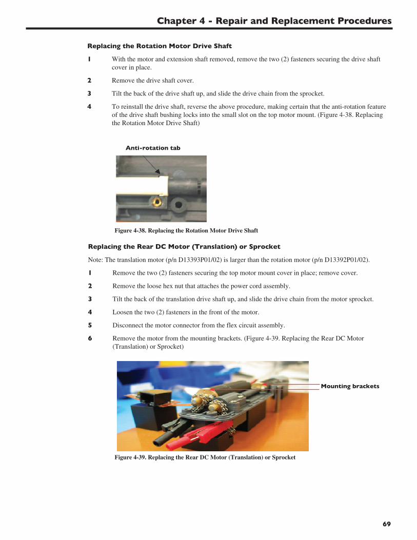
Chapter 4 - Repair and Replacement Procedures
69
Replacing the Rotation Motor Drive Shaft
1 With the motor and extension shaft removed, remove the two (2) fasteners securing the drive shaft cover in place.
2 Remove the drive shaft cover.
3 Tilt the back of the drive shaft up, and slide the drive chain from the sprocket.
4 To reinstall the drive shaft, reverse the above procedure, making certain that the anti-rotation feature of the drive shaft bushing locks into the small slot on the top motor mount. (Figure 4-38. Replacing the Rotation Motor Drive Shaft)
Figure 4-38. Replacing the Rotation Motor Drive Shaft
Anti-rotation tab
Replacing the Rear DC Motor (Translation) or Sprocket
Note: The translation motor (p/n D13393P01/02) is larger than the rotation motor (p/n D13392P01/02).
1 Remove the two (2) fasteners securing the top motor mount cover in place; remove cover.
2 Remove the loose hex nut that attaches the power cord assembly.
3 Tilt the back of the translation drive shaft up, and slide the drive chain from the motor sprocket.
4 Loosen the two (2) fasteners in the front of the motor.
5 Disconnect the motor connector from the flex circuit assembly.
6 Remove the motor from the mounting brackets. (Figure 4-39. Replacing the Rear DC Motor (Translation) or Sprocket)
Figure 4-39. Replacing the Rear DC Motor (Translation) or Sprocket
Mounting brackets
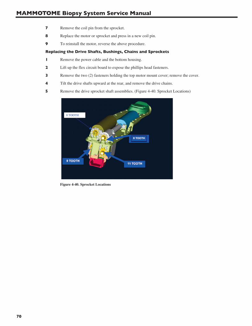
MAMMOTOME Biopsy System Service Manual
70
7 Remove the coil pin from the sprocket.
8 Replace the motor or sprocket and press in a new coil pin.
9 To reinstall the motor, reverse the above procedure.
Replacing the Drive Shafts, Bushings, Chains and Sprockets
1 Remove the power cable and the bottom housing.
2 Lift up the flex circuit board to expose the phillips head fasteners.
3 Remove the two (2) fasteners holding the top motor mount cover; remove the cover.
4 Tilt the drive shafts upward at the rear, and remove the drive chains.
5 Remove the drive sprocket shaft assemblies. (Figure 4-40. Sprocket Locations)
Figure 4-40. Sprocket Locations
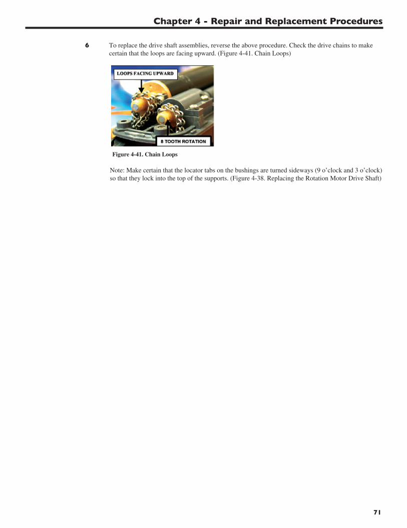
Chapter 4 - Repair and Replacement Procedures
71
6 To replace the drive shaft assemblies, reverse the above procedure. Check the drive chains to make certain that the loops are facing upward. (Figure 4-41. Chain Loops)
Figure 4-41. Chain Loops
Note: Make certain that the locator tabs on the bushings are turned sideways (9 o’clock and 3 o’clock)so that they lock into the top of the supports. (Figure 4-38. Replacing the Rotation Motor Drive Shaft)
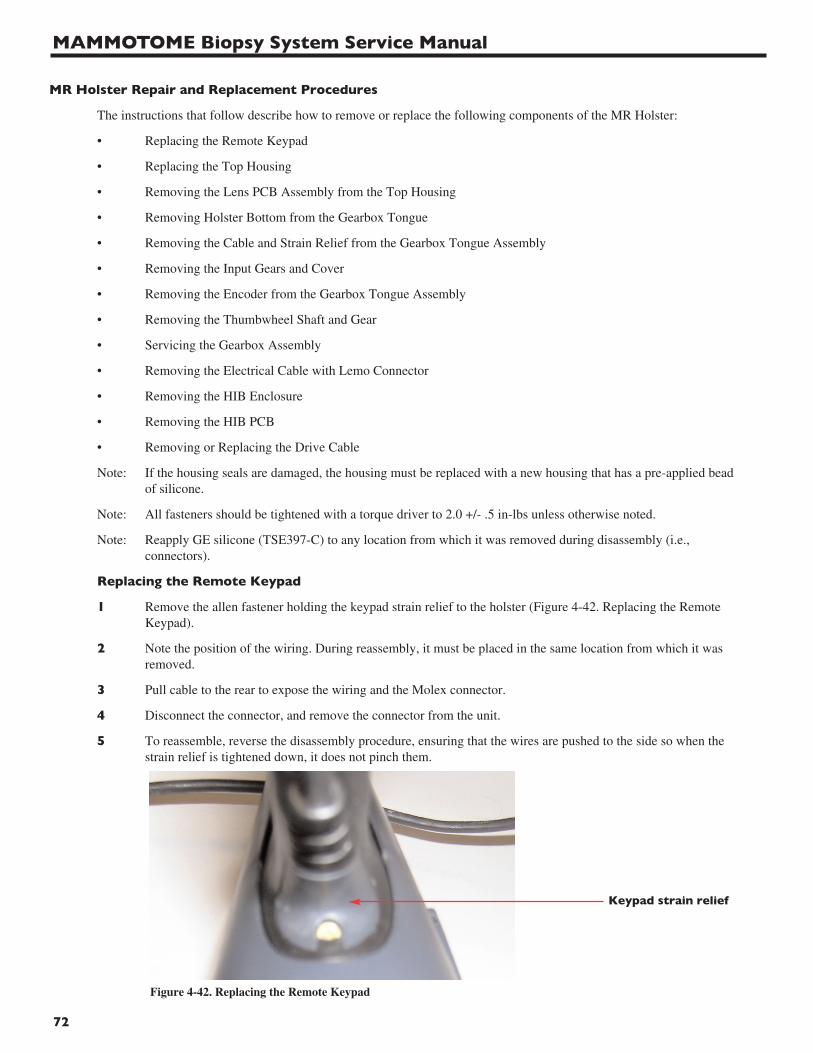
MAMMOTOME Biopsy System Service Manual
72
MR Holster Repair and Replacement Procedures
The instructions that follow describe how to remove or replace the following components of the MR Holster:
• Replacing the Remote Keypad
• Replacing the Top Housing
• Removing the Lens PCB Assembly from the Top Housing
• Removing Holster Bottom from the Gearbox Tongue
• Removing the Cable and Strain Relief from the Gearbox Tongue Assembly
• Removing the Input Gears and Cover
• Removing the Encoder from the Gearbox Tongue Assembly
• Removing the Thumbwheel Shaft and Gear
• Servicing the Gearbox Assembly
• Removing the Electrical Cable with Lemo Connector
• Removing the HIB Enclosure
• Removing the HIB PCB
• Removing or Replacing the Drive Cable
Note: If the housing seals are damaged, the housing must be replaced with a new housing that has a pre-applied bead of silicone.
Note: All fasteners should be tightened with a torque driver to 2.0 +/- .5 in-lbs unless otherwise noted.
Note: Reapply GE silicone (TSE397-C) to any location from which it was removed during disassembly (i.e., connectors).
Replacing the Remote Keypad
1 Remove the allen fastener holding the keypad strain relief to the holster (Figure 4-42. Replacing the Remote Keypad).
2 Note the position of the wiring. During reassembly, it must be placed in the same location from which it was removed.
3 Pull cable to the rear to expose the wiring and the Molex connector.
4 Disconnect the connector, and remove the connector from the unit.
5 To reassemble, reverse the disassembly procedure, ensuring that the wires are pushed to the side so when the strain relief is tightened down, it does not pinch them.
Figure 4-42. Replacing the Remote Keypad
Keypad strain relief
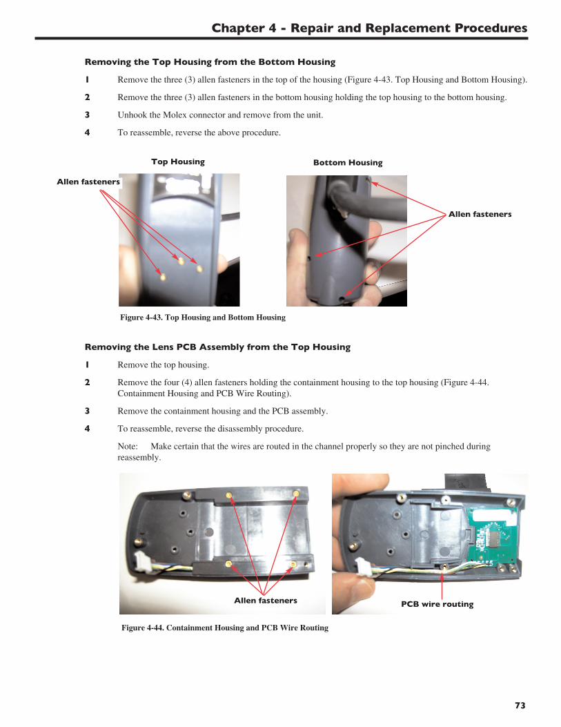
Chapter 4 - Repair and Replacement Procedures
73
Removing the Top Housing from the Bottom Housing
1 Remove the three (3) allen fasteners in the top of the housing (Figure 4-43. Top Housing and Bottom Housing).
2 Remove the three (3) allen fasteners in the bottom housing holding the top housing to the bottom housing.
3 Unhook the Molex connector and remove from the unit.
4 To reassemble, reverse the above procedure.
Figure 4-43. Top Housing and Bottom Housing
Top Housing
Removing the Lens PCB Assembly from the Top Housing
1 Remove the top housing.
2 Remove the four (4) allen fasteners holding the containment housing to the top housing (Figure 4-44. Containment Housing and PCB Wire Routing).
3 Remove the containment housing and the PCB assembly.
4 To reassemble, reverse the disassembly procedure.
Note: Make certain that the wires are routed in the channel properly so they are not pinched duringreassembly.
Figure 4-44. Containment Housing and PCB Wire Routing
Bottom Housing
Allen fasteners
Allen fasteners
PCB wire routingAllen fasteners
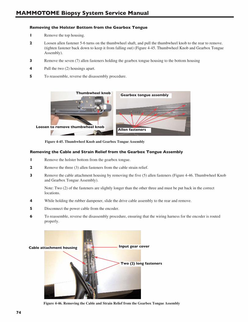
MAMMOTOME Biopsy System Service Manual
74
Removing the Holster Bottom from the Gearbox Tongue
1 Remove the top housing.
2 Loosen allen fastener 5-6 turns on the thumbwheel shaft, and pull the thumbwheel knob to the rear to remove. (tighten fastener back down to keep it from falling out) (Figure 4-45. Thumbwheel Knob and Gearbox Tongue Assembly).
3 Remove the seven (7) allen fasteners holding the gearbox tongue housing to the bottom housing
4 Pull the two (2) housings apart.
5 To reassemble, reverse the disassembly procedure.
Figure 4-45. Thumbwheel Knob and Gearbox Tongue Assembly
Removing the Cable and Strain Relief from the Gearbox Tongue Assembly
1 Remove the holster bottom from the gearbox tongue.
2 Remove the three (3) allen fasteners from the cable strain relief.
3 Remove the cable attachment housing by removing the five (5) allen fasteners (Figure 4-46. Thumbwheel Knoband Gearbox Tongue Assembly).
Note: Two (2) of the fasteners are slightly longer than the other three and must be put back in the correct locations.
4 While holding the rubber dampener, slide the drive cable assembly to the rear and remove.
5 Disconnect the power cable from the encoder.
6 To reassemble, reverse the disassembly procedure, ensuring that the wiring harness for the encoder is routed properly.
Figure 4-46. Removing the Cable and Strain Relief from the Gearbox Tongue Assembly
Loosen to remove thumbwheel knobAllen fasteners
Thumbwheel knob Gearbox tongue assembly
Input gear cover
Two (2) long fasteners
Cable attachment housing
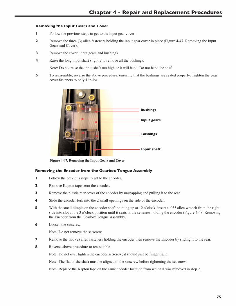
Chapter 4 - Repair and Replacement Procedures
75
Removing the Input Gears and Cover
1 Follow the previous steps to get to the input gear cover.
2 Remove the three (3) allen fasteners holding the input gear cover in place (Figure 4-47. Removing the Input Gears and Cover).
3 Remove the cover, input gears and bushings.
4 Raise the long input shaft slightly to remove all the bushings.
Note: Do not raise the input shaft too high or it will bend. Do not bend the shaft.
5 To reassemble, reverse the above procedure, ensuring that the bushings are seated properly. Tighten the gear cover fasteners to only 1 in-lbs.
Figure 4-47. Removing the Input Gears and Cover
Removing the Encoder from the Gearbox Tongue Assembly
1 Follow the previous steps to get to the encoder.
2 Remove Kapton tape from the encoder.
3 Remove the plastic rear cover of the encoder by unsnapping and pulling it to the rear.
4 Slide the encoder fork into the 2 small openings on the side of the encoder.
5 With the small dimple on the encoder shaft pointing up at 12 o’clock, insert a .035 allen wrench from the right side into slot at the 3 o’clock position until it seats in the setscrew holding the encoder (Figure 4-48. Removingthe Encoder from the Gearbox Tongue Assembly).
6 Loosen the setscrew.
Note: Do not remove the setscrew.
7 Remove the two (2) allen fasteners holding the encoder then remove the Encoder by sliding it to the rear.
8 Reverse above procedure to reassemble
Note: Do not over tighten the encoder setscrew; it should just be finger tight.
Note: The flat of the shaft must be aligned to the setscrew before tightening the setscrew.
Note: Replace the Kapton tape on the same encoder location from which it was removed in step 2.
Bushings
Input gears
Bushings
Input shaft
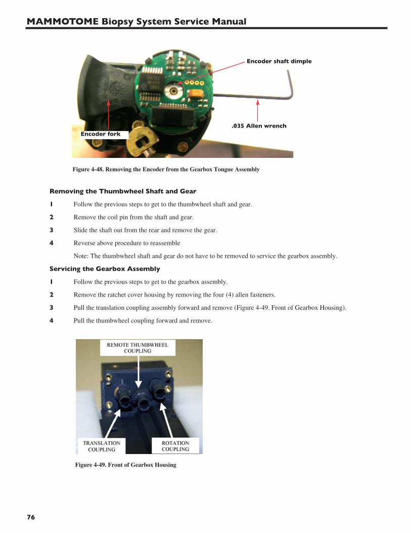
MAMMOTOME Biopsy System Service Manual
76
Removing the Thumbwheel Shaft and Gear
1 Follow the previous steps to get to the thumbwheel shaft and gear.
2 Remove the coil pin from the shaft and gear.
3 Slide the shaft out from the rear and remove the gear.
4 Reverse above procedure to reassemble
Note: The thumbwheel shaft and gear do not have to be removed to service the gearbox assembly.
Servicing the Gearbox Assembly
1 Follow the previous steps to get to the gearbox assembly.
2 Remove the ratchet cover housing by removing the four (4) allen fasteners.
3 Pull the translation coupling assembly forward and remove (Figure 4-49. Front of Gearbox Housing).
4 Pull the thumbwheel coupling forward and remove.
Figure 4-49. Front of Gearbox Housing
Figure 4-48. Removing the Encoder from the Gearbox Tongue Assembly
Encoder shaft dimple
Encoder fork.035 Allen wrench
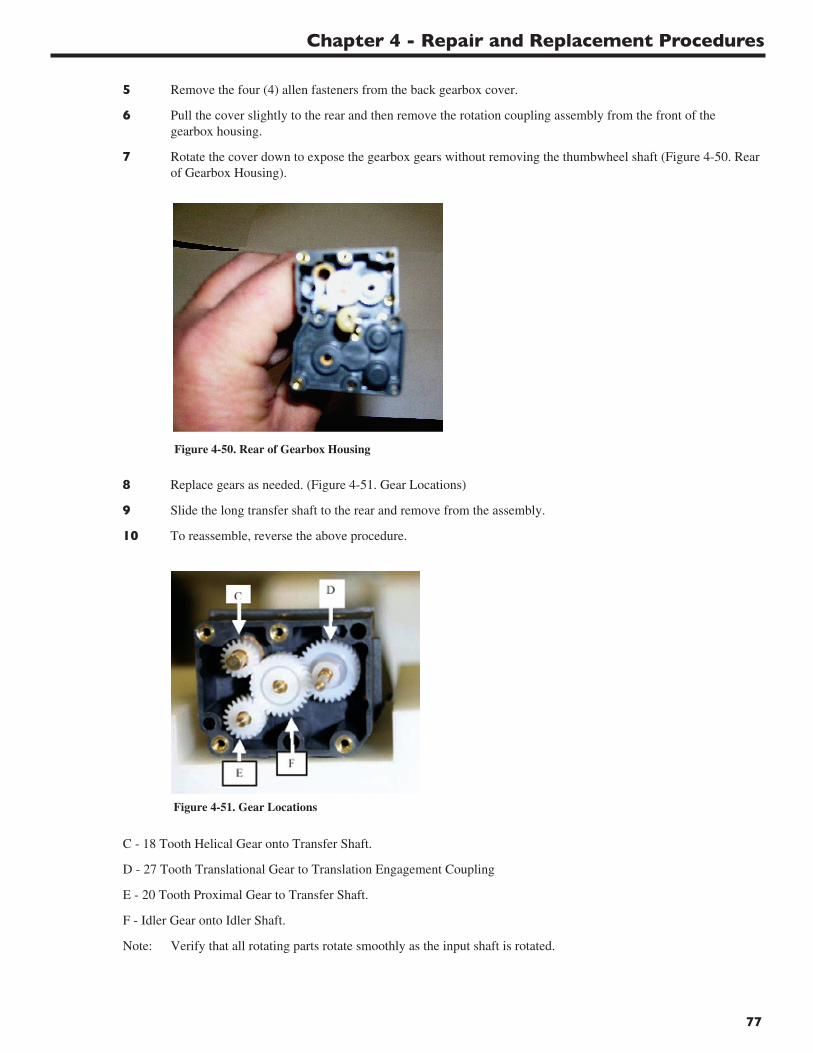
Chapter 4 - Repair and Replacement Procedures
77
5 Remove the four (4) allen fasteners from the back gearbox cover.
6 Pull the cover slightly to the rear and then remove the rotation coupling assembly from the front of the gearbox housing.
7 Rotate the cover down to expose the gearbox gears without removing the thumbwheel shaft (Figure 4-50. Rear of Gearbox Housing).
Figure 4-50. Rear of Gearbox Housing
8 Replace gears as needed. (Figure 4-51. Gear Locations)
9 Slide the long transfer shaft to the rear and remove from the assembly.
10 To reassemble, reverse the above procedure.
Figure 4-51. Gear Locations
C - 18 Tooth Helical Gear onto Transfer Shaft.
D - 27 Tooth Translational Gear to Translation Engagement Coupling
E - 20 Tooth Proximal Gear to Transfer Shaft.
F - Idler Gear onto Idler Shaft.
Note: Verify that all rotating parts rotate smoothly as the input shaft is rotated.
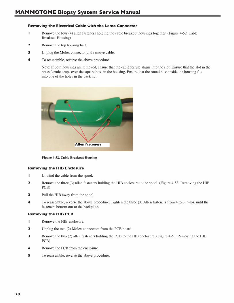
MAMMOTOME Biopsy System Service Manual
78
Removing the HIB Enclosure
1 Unwind the cable from the spool.
2 Remove the three (3) allen fasteners holding the HIB enclosure to the spool. (Figure 4-53. Removing the HIB PCB)
3 Pull the HIB away from the spool.
4 To reassemble, reverse the above procedure. Tighten the three (3) Allen fasteners from 4 to 6 in-lbs. until the fasteners bottom out to the backplate.
Removing the HIB PCB
1 Remove the HIB enclosure.
2 Unplug the two (2) Molex connectors from the PCB board.
3 Remove the two (2) allen fasteners holding the PCB to the HIB enclosure. (Figure 4-53. Removing the HIB PCB)
4 Remove the PCB from the enclosure.
5 To reassemble, reverse the above procedure.
Figure 4-52. Cable Breakout Housing
Removing the Electrical Cable with the Lemo Connector
1 Remove the four (4) allen fasteners holding the cable breakout housings together. (Figure 4-52. Cable Breakout Housing)
2 Remove the top housing half.
3 Unplug the Molex connector and remove cable.
4 To reassemble, reverse the above procedure.
Note: If both housings are removed, ensure that the cable ferrule aligns into the slot. Ensure that the slot in the brass ferrule drops over the square boss in the housing. Ensure that the round boss inside the housing fits into one of the holes in the back nut.
Allen fasteners
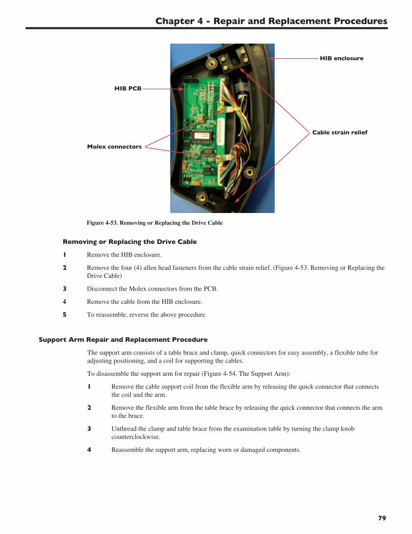
Chapter 4 - Repair and Replacement Procedures
79
Figure 4-53. Removing or Replacing the Drive Cable
Removing or Replacing the Drive Cable
1 Remove the HIB enclosure.
2 Remove the four (4) allen head fasteners from the cable strain relief. (Figure 4-53. Removing or Replacing the Drive Cable)
3 Disconnect the Molex connectors from the PCB.
4 Remove the cable from the HIB enclosure.
5 To reassemble, reverse the above procedure.
HIB enclosure
HIB PCB
Cable strain relief
Support Arm Repair and Replacement Procedure
The support arm consists of a table brace and clamp, quick connectors for easy assembly, a flexible tube foradjusting positioning, and a coil for supporting the cables.
To disassemble the support arm for repair (Figure 4-54. The Support Arm):
1 Remove the cable support coil from the flexible arm by releasing the quick connector that connectsthe coil and the arm.
2 Remove the flexible arm from the table brace by releasing the quick connector that connects the armto the brace.
3 Unthread the clamp and table brace from the examination table by turning the clamp knobcounterclockwise.
4 Reassemble the support arm, replacing worn or damaged components.
Molex connectors

MAMMOTOME Biopsy System Service Manual
80
Cart Assembly Repair and Replacement Procedures
This section describes how to replace the following cart assembly components:
• Cart handle
• Holster receptacle and bracket
• Power cord wrap posts
• Casters
• Cart door latch
• Cart door and hinges
• Pull-out drawer guides
• Fastener plate
Figure 4-54. The Support Arm
Flexible arm
Quick connector
Quickconnector
Table brace
Clamp knobClamp
Cablesupportcoil
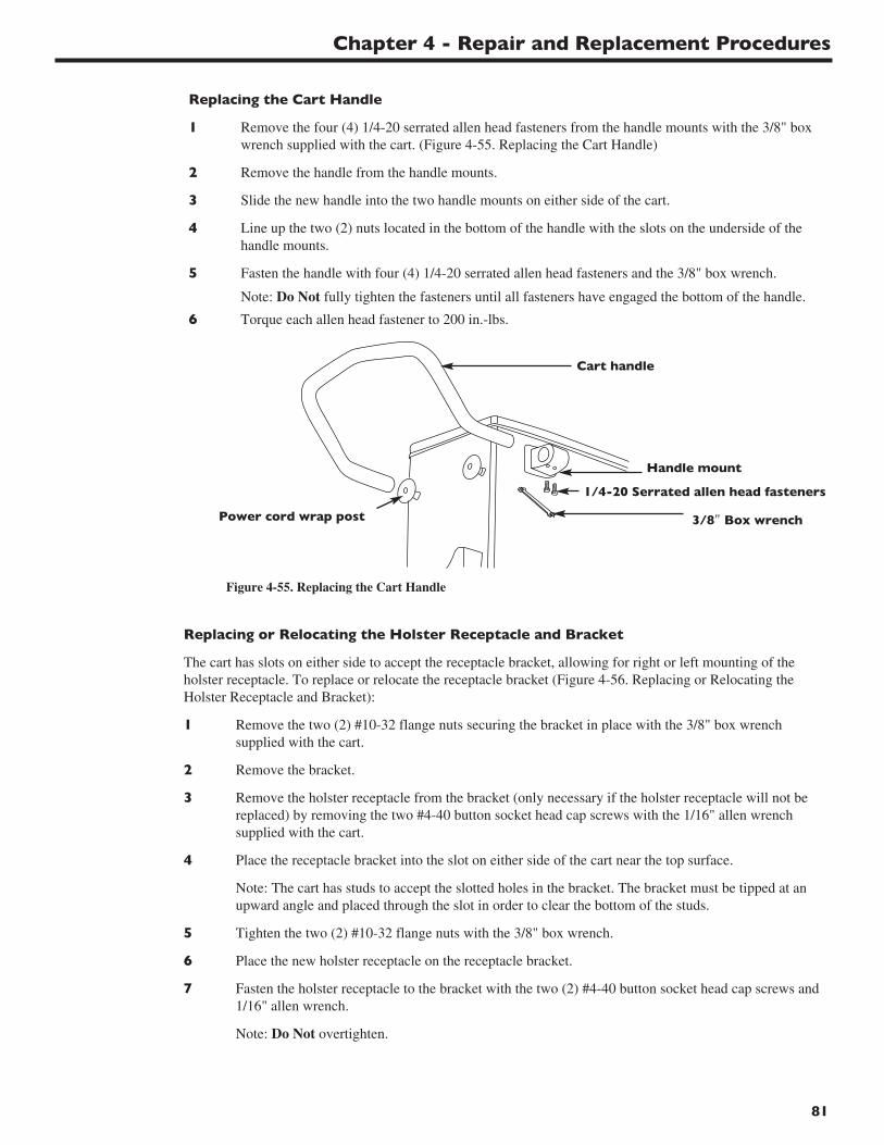
Chapter 4 - Repair and Replacement Procedures
81
Replacing the Cart Handle
1 Remove the four (4) 1/4-20 serrated allen head fasteners from the handle mounts with the 3/8" boxwrench supplied with the cart. (Figure 4-55. Replacing the Cart Handle)
2 Remove the handle from the handle mounts.
3 Slide the new handle into the two handle mounts on either side of the cart.
4 Line up the two (2) nuts located in the bottom of the handle with the slots on the underside of thehandle mounts.
5 Fasten the handle with four (4) 1/4-20 serrated allen head fasteners and the 3/8" box wrench.
Note: Do Not fully tighten the fasteners until all fasteners have engaged the bottom of the handle.
6 Torque each allen head fastener to 200 in.-lbs.
Cart handle
Handle mount
1/4-20 Serrated allen head fasteners
3/8" Box wrenchPower cord wrap post
Figure 4-55. Replacing the Cart Handle
Replacing or Relocating the Holster Receptacle and Bracket
The cart has slots on either side to accept the receptacle bracket, allowing for right or left mounting of theholster receptacle. To replace or relocate the receptacle bracket (Figure 4-56. Replacing or Relocating theHolster Receptacle and Bracket):
1 Remove the two (2) #10-32 flange nuts securing the bracket in place with the 3/8" box wrenchsupplied with the cart.
2 Remove the bracket.
3 Remove the holster receptacle from the bracket (only necessary if the holster receptacle will not bereplaced) by removing the two #4-40 button socket head cap screws with the 1/16" allen wrenchsupplied with the cart.
4 Place the receptacle bracket into the slot on either side of the cart near the top surface.
Note: The cart has studs to accept the slotted holes in the bracket. The bracket must be tipped at anupward angle and placed through the slot in order to clear the bottom of the studs.
5 Tighten the two (2) #10-32 flange nuts with the 3/8" box wrench.
6 Place the new holster receptacle on the receptacle bracket.
7 Fasten the holster receptacle to the bracket with the two (2) #4-40 button socket head cap screws and1/16" allen wrench.
Note: Do Not overtighten.
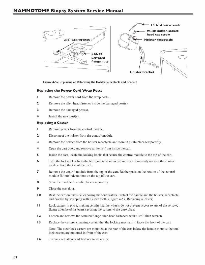
MAMMOTOME Biopsy System Service Manual
82
Replacing the Power Cord Wrap Posts
1 Remove the power cord from the wrap posts.
2 Remove the allen head fastener inside the damaged post(s).
3 Remove the damaged post(s).
4 Install the new post(s).
Replacing a Caster
1 Remove power from the control module.
2 Disconnect the holster from the control module.
3 Remove the holster from the holster receptacle and store in a safe place temporarily.
4 Open the cart door, and remove all items from inside the cart.
5 Inside the cart, locate the locking knobs that secure the control module to the top of the cart.
6 Turn the locking knobs to the left (counter-clockwise) until you can easily remove the controlmodule from the top of the cart.
7 Remove the control module from the top of the cart. Rubber pads on the bottom of the controlmodule fit into indentations on the top of the cart.
8 Store the module in a safe place temporarily.
9 Close the cart door.
10 Rest the cart on one side, exposing the four casters. Protect the handle and the holster, receptacle,and bracket by wrapping with a clean cloth. (Figure 4-57. Replacing a Caster)
11 Lock casters in place, making certain that the wheels do not prevent access to any of the serratedflange allen head fasteners securing the casters to the base plate.
12 Loosen and remove the serrated flange allen head fasteners with a 3/8" allen wrench.
13 Replace the caster(s), making certain that the locking mechanism faces the front of the cart.
Note: The steer lock casters are mounted at the rear of the cart below the handle mounts; the totallock casters are mounted in front of the cart.
14 Torque each allen head fastener to 20 in.-lbs.
#10-32Serratedflange nuts
1/16" Allen wrench
Holster receptacle
#4-40 Button sockethead cap screw
Holster bracket
3/8" Box wrench
Figure 4-56. Replacing or Relocating the Holster Receptacle and Bracket
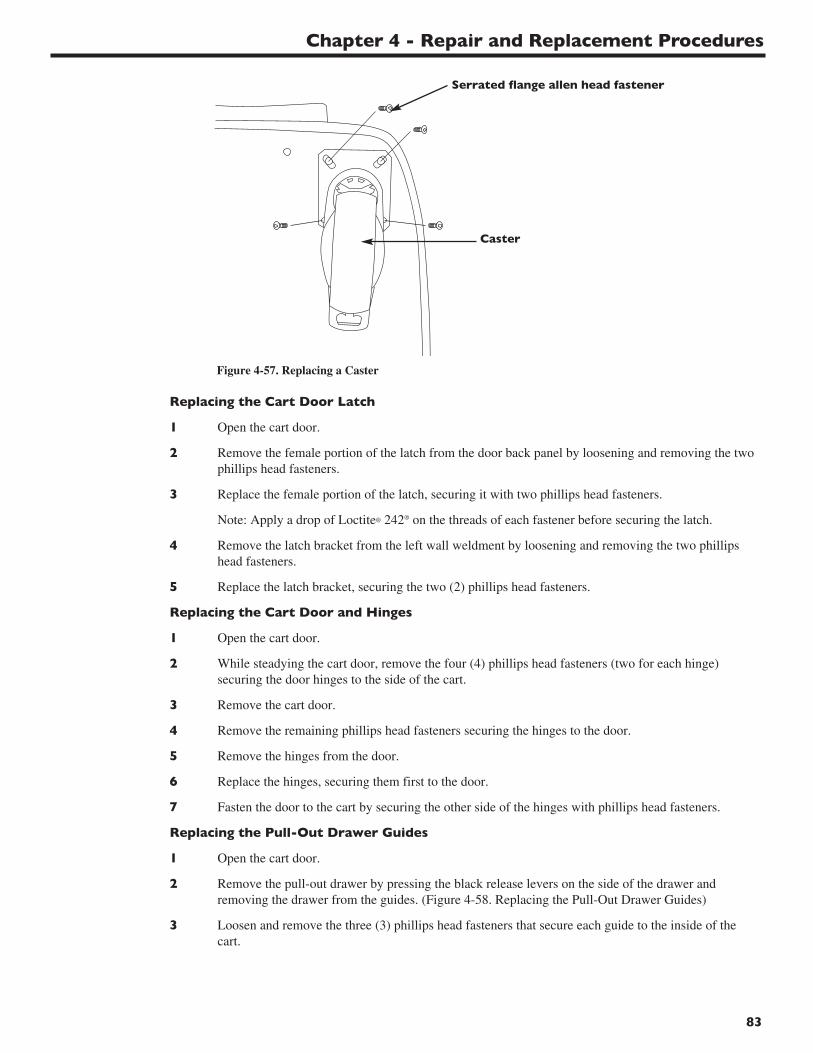
Chapter 4 - Repair and Replacement Procedures
83
Replacing the Cart Door Latch
1 Open the cart door.
2 Remove the female portion of the latch from the door back panel by loosening and removing the twophillips head fasteners.
3 Replace the female portion of the latch, securing it with two phillips head fasteners.
Note: Apply a drop of Loctite® 242® on the threads of each fastener before securing the latch.
4 Remove the latch bracket from the left wall weldment by loosening and removing the two phillipshead fasteners.
5 Replace the latch bracket, securing the two (2) phillips head fasteners.
Replacing the Cart Door and Hinges
1 Open the cart door.
2 While steadying the cart door, remove the four (4) phillips head fasteners (two for each hinge)securing the door hinges to the side of the cart.
3 Remove the cart door.
4 Remove the remaining phillips head fasteners securing the hinges to the door.
5 Remove the hinges from the door.
6 Replace the hinges, securing them first to the door.
7 Fasten the door to the cart by securing the other side of the hinges with phillips head fasteners.
Replacing the Pull-Out Drawer Guides
1 Open the cart door.
2 Remove the pull-out drawer by pressing the black release levers on the side of the drawer andremoving the drawer from the guides. (Figure 4-58. Replacing the Pull-Out Drawer Guides)
3 Loosen and remove the three (3) phillips head fasteners that secure each guide to the inside of thecart.
Caster
Serrated flange allen head fastener
Figure 4-57. Replacing a Caster
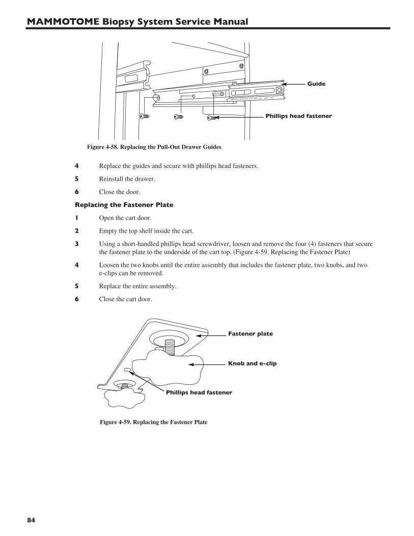
MAMMOTOME Biopsy System Service Manual
84
4 Replace the guides and secure with phillips head fasteners.
5 Reinstall the drawer.
6 Close the door.
Replacing the Fastener Plate
1 Open the cart door.
2 Empty the top shelf inside the cart.
3 Using a short-handled phillips head screwdriver, loosen and remove the four (4) fasteners that securethe fastener plate to the underside of the cart top. (Figure 4-59. Replacing the Fastener Plate)
4 Loosen the two knobs until the entire assembly that includes the fastener plate, two knobs, and twoe-clips can be removed.
5 Replace the entire assembly.
6 Close the cart door.
Figure 4-59. Replacing the Fastener Plate
Fastener plate
Knob and e-clip
Phillips head fastener
Phillips head fastener
Guide
Figure 4-58. Replacing the Pull-Out Drawer Guides

Chapter 5 - System Upgrades
Introduction
The following upgrades should be inspected for and performed, as required, on the MAMMOTOME Control Module (SCM12 & SCM23).
Part / Assembly Original Condition Upgrade to Requirement
Software Hand Held (any version 3.0 and prior) v4.1 or higher. MandatoryFor installation instructions,refer to the MAMMOTOMESoftware Installation Guide(p/n P40491P01) with theSCMSW5 software.
Software Stereotactic (any version 2.0 and prior) v4.1 or higher. MandatoryFor installation instructions,refer to the MAMMOTOMESoftware Installation Guide(p/n P40491P01) with theSCMSW5 software.
Regulatory Label p/n 880-000360 or p/n 880-000389 Remove existing label Mandatorywithout a heart symbol in the upper and replace withleft-hand area of the label p/n D06239P02.
Ground Wire See Ground Wire See Ground Wire MandatoryHardware Installation Installation
instructions in this instructions in thischapter. chapter.
Warranty Label No label present Place label (p/n 3432.325) Mandatoryover one screw underthe front bezel.
Uniboard All Uniboards 3432.007 See Uniboard Upgrade MandatoryECN 017789 or earlier instructions in this chapter.
Pump Wiring Wires not routed under the power See Routing of Pump Mandatorysupply bracket Wiring instructions in
this chapter.
Vacuum Pump and See Change in Vacuum Pump and See Change in Vacuum As neededIsolation Mounts Components instructions in this chapter. Pump and Components
instructions in this chapter.
Vacuum Tubing See Vacuum Tubing Upgrade See Vacuum Tubing Mandatoryinstructions in this chapter. Upgrade instructions in
this chapter.
DC Motor Adapter See DC Motor Adapter Upgrade See DC Motor Adapter Domestic - instructions in this chapter. Upgrade instructions Mandatory;
in this chapter. Int’l - As needed
Regulatory Label See Regulatory Label Upgrade See Regulatory Label Mandatoryinstructions in this chapter. Upgrade instructions
in this chapter.
85

MAMMOTOME Biopsy System Service Manual
86
EX Upgrade See EX Upgrade See EX On request.instructions in this chapter. Upgrade instructions in
this chapter.
MR Cart Upgrade See MR Cart Upgrade instructions See MR Cart Upgrade MR system in this chapter. instructions in this chapter. installation
Note: Upgrade requirements are defined as follows:• As Needed: This upgrade should only be performed if the affected part or assembly has
failed.• Upon Request: This upgrade should only be performed if specifically requested by the
customer.• Mandatory: This upgrade must be performed if the unit is not already in the upgraded
configuration
The following upgrades should be inspected for and performed, as required, on the Stereotactic Holster (STHC1).
Part / Assembly Original Condition/Upgrade to Requirement
Rear Thumbwheel Assembly See Replacing the ST Holster Rotation MandatoryKnob instructions in this chapter.
Spade and Coupling Assembly See Replacing the ST Holster Rotation Mandatoryinstructions in this chapter.
Coil Pin Replacement See Coil Pin Replacement instructions Mandatoryin this chapter.
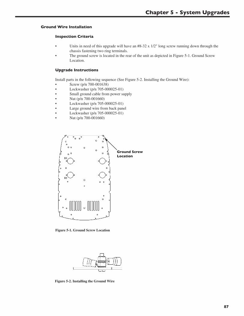
Chapter 5 - System Upgrades
87
Figure 5-1. Ground Screw Location
Figure 5-2. Installing the Ground Wire
Ground ScrewLocation
Ground Wire Installation
Inspection Criteria
• Units in need of this upgrade will have an #8-32 x 1/2" long screw running down through the chassis fastening two ring terminals.
• The ground screw is located in the rear of the unit as depicted in Figure 5-1. Ground Screw Location.
Upgrade Instructions
Install parts in the following sequence (See Figure 5-2. Installing the Ground Wire):• Screw (p/n 700-001638)• Lockwasher (p/n 705-000025-01)• Small ground cable from power supply• Nut (p/n 700-001660)• Lockwasher (p/n 705-000025-01)• Large ground wire from back panel• Lockwasher (p/n 705-000025-01)• Nut (p/n 700-001660)
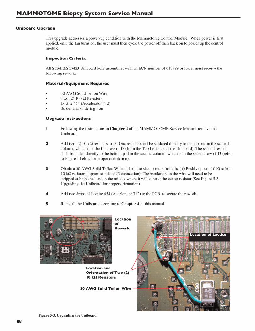
MAMMOTOME Biopsy System Service Manual
88
Uniboard Upgrade
This upgrade addresses a power-up condition with the Mammotome Control Module. When power is first applied, only the fan turns on; the user must then cycle the power off then back on to power up the control module.
Inspection Criteria
All SCM12/SCM23 Uniboard PCB assemblies with an ECN number of 017789 or lower must receive the following rework.
Material/Equipment Required
• 30 AWG Solid Teflon Wire• Two (2) 10 kΩ Resistors• Loctite 454 (Accelerator 712)• Solder and soldering iron
Upgrade Instructions
1 Following the instructions in Chapter 4 of the MAMMOTOME Service Manual, remove the Uniboard.
2 Add two (2) 10 kΩ resistors to J3. One resistor shall be soldered directly to the top pad in the second column, which is in the first row of J3 (from the Top Left side of the Uniboard). The second resistor shall be added directly to the bottom pad in the second column, which is in the second row of J3 (referto Figure 1 below for proper orientation).
3 Obtain a 30 AWG Solid Teflon Wire and trim to size to route from the (+) Positive post of C90 to both10 kΩ resistors (opposite side of J3 connection). The insulation on the wire will need to be stripped at both ends and in the middle where it will contact the center resistor (See Figure 5-3. Upgrading the Uniboard for proper orientation).
4 Add two drops of Loctite 454 (Accelerator 712) to the PCB, to secure the rework.
5 Reinstall the Uniboard according to Chapter 4 of this manual.
Locationof Rework
Figure 5-3. Upgrading the Uniboard
Location andOrientation of Two (2)10 kΩ Resistors
30 AWG Solid Teflon Wire
Location of Loctite
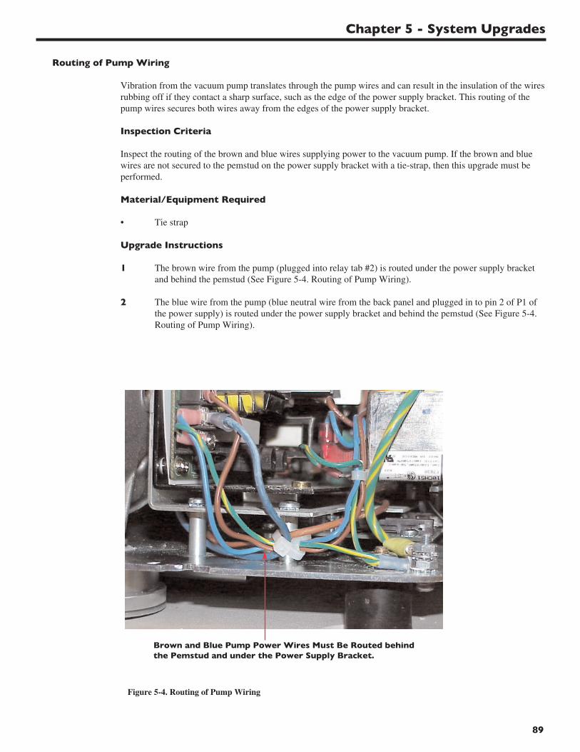
Chapter 5 - System Upgrades
89
Routing of Pump Wiring
Vibration from the vacuum pump translates through the pump wires and can result in the insulation of the wiresrubbing off if they contact a sharp surface, such as the edge of the power supply bracket. This routing of the pump wires secures both wires away from the edges of the power supply bracket.
Inspection Criteria
Inspect the routing of the brown and blue wires supplying power to the vacuum pump. If the brown and blue wires are not secured to the pemstud on the power supply bracket with a tie-strap, then this upgrade must be performed.
Material/Equipment Required
• Tie strap
Upgrade Instructions
1 The brown wire from the pump (plugged into relay tab #2) is routed under the power supply bracket and behind the pemstud (See Figure 5-4. Routing of Pump Wiring).
2 The blue wire from the pump (blue neutral wire from the back panel and plugged in to pin 2 of P1 of the power supply) is routed under the power supply bracket and behind the pemstud (See Figure 5-4. Routing of Pump Wiring).
Brown and Blue Pump Power Wires Must Be Routed behindthe Pemstud and under the Power Supply Bracket.
Figure 5-4. Routing of Pump Wiring

MAMMOTOME Biopsy System Service Manual
90
Change in Vacuum Pump and Components
Part Number Part Description For Use With Special Instructions
875-000303 Old Vacuum Pump All SCM23s Existing inventory should bemodel #2639VGH44-337A depleted prior to transitioning
to p/n 875-000302.
875-000336 New Vacuum Pump All SCM12s Existing inventory of pumpsmodel #2669VES44-337 (model # K48ZZDZH3250)
should be depleted first.
875-000302 New Vacuum Pump All SCM23s Existing inventory of pumps model #2669VGH144-337 (model # 2639VGH44-337A)
should be depleted first.
700-001500 New Pump Isolation Mount All versions of pumps All 4 isolation mounts must befor SCM12 and SCM23 the same version.
700-001930 7/16 Size 1/2" ID 1-1/4" New Pump Isolation Mount Additional washer placed OD 5/64" Thick, Round Flat (p/n 700-001500) before the fender washer Washer, Zinc Plated (Refer to step 5).
700-000396-2 8-32 x 3/8" Phillips Pan Head New vacuum pumps Refer to step 15.SEM Screw for LCD Turntable (model #2669VES44-337
or 2669VGH144-337)
700-001529 1/4-20 x 1-1/2" Black Oxide Hex Old Vacuum Pumps Remaining inventory shouldDrive Button Head Screw (model # K48ZZDZH3250 be scrapped and replaced
or 2639VGH44-337A) with p/n 3432.367.
3432.367 1/4-20 x 1-1/2" Stainless Steel Old Vacuum Pumps Single use screw that mustTorx Drive Button Head Screw (model # K48ZZDZH3250 be discarded when removed.with pre-applied epoxy or 2639VGH44-337A)
3432.366 1/4-20 x 1-1/4" Stainless Steel New Vacuum Pumps Single use screw that mustTorx Drive Button Head Screw (model #2669VES44-337 be discarded when removed.with pre-applied epoxy or 2669VGH144-337)
700-001929 90˚ Elbow Adapter New Vacuum Pumps Provides additional clearance(model #2669VES44-337 for the tubing.or 2669VGH144-337)
Description of Changes in the Isolation Mount
The isolation mount was changed to allow for more clearance with the new pump. The new mount is for use with all versions of the vacuum pump, part numbers 875-000336, 875-000303 and 875-000302. The new mount requires the addition of a 7/16 Size 1/2" ID 1-1/4" OD 5/64" thick, round flat washer (p/n 700-001930) before the fender washer to allow for clearance of the pump mount bolt. Units must have all four (4) of the same version of the mount; the mounts are not interchangeable on a unit due to differences between the two versions of mounts.
Description of Changes in the Pump Mount Screws
The screws used for securing the isolation mounts to the pump were modified to:• Standardize the application of a thread locker material that prevents the fastener from loosening due to both the
vibration and heat induced by the vacuum pump.• Improve the strength of the fastener head by changing to a torx drive that would minimize “stripping” of the
fastener head while tightening the fastener to 120 in-lbs.
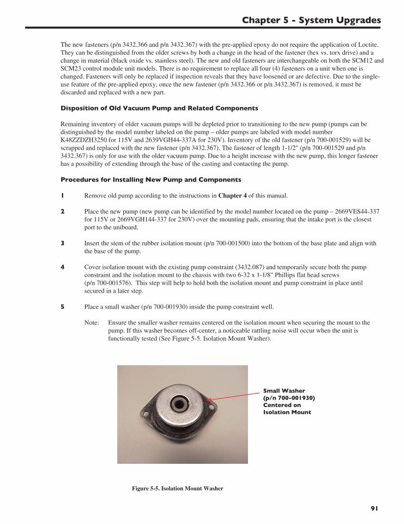
Chapter 5 - System Upgrades
91
The new fasteners (p/n 3432.366 and p/n 3432.367) with the pre-applied epoxy do not require the application of Loctite. They can be distinguished from the older screws by both a change in the head of the fastener (hex vs. torx drive) and a change in material (black oxide vs. stainless steel). The new and old fasteners are interchangeable on both the SCM12 and SCM23 control module unit models. There is no requirement to replace all four (4) fasteners on a unit when one is changed. Fasteners will only be replaced if inspection reveals that they have loosened or are defective. Due to the single-use feature of the pre-applied epoxy, once the new fastener (p/n 3432.366 or p/n 3432.367) is removed, it must be discarded and replaced with a new part.
Disposition of Old Vacuum Pump and Related Components
Remaining inventory of older vacuum pumps will be depleted prior to transitioning to the new pump (pumps can be distinguished by the model number labeled on the pump – older pumps are labeled with model number K48ZZDZH3250 for 115V and 2639VGH44-337A for 230V). Inventory of the old fastener (p/n 700-001529) will be scrapped and replaced with the new fastener (p/n 3432.367). The fastener of length 1-1/2" (p/n 700-001529 and p/n 3432.367) is only for use with the older vacuum pump. Due to a height increase with the new pump, this longer fastener has a possibility of extending through the base of the casting and contacting the pump.
Procedures for Installing New Pump and Components
1 Remove old pump according to the instructions in Chapter 4 of this manual.
2 Place the new pump (new pump can be identified by the model number located on the pump – 2669VES44-337 for 115V or 2669VGH144-337 for 230V) over the mounting pads, ensuring that the intake port is the closest port to the uniboard.
3 Insert the stem of the rubber isolation mount (p/n 700-001500) into the bottom of the base plate and align with the base of the pump.
4 Cover isolation mount with the existing pump constraint (3432.087) and temporarily secure both the pump constraint and the isolation mount to the chassis with two 6-32 x 1-1/8" Phillips flat head screws (p/n 700-001576). This step will help to hold both the isolation mount and pump constraint in place until secured in a later step.
5 Place a small washer (p/n 700-001930) inside the pump constraint well.
Note: Ensure the smaller washer remains centered on the isolation mount when securing the mount to the pump. If this washer becomes off-center, a noticeable rattling noise will occur when the unit is functionally tested (See Figure 5-5. Isolation Mount Washer).
Small Washer(p/n 700-001930)Centered onIsolation Mount
Figure 5-5. Isolation Mount Washer
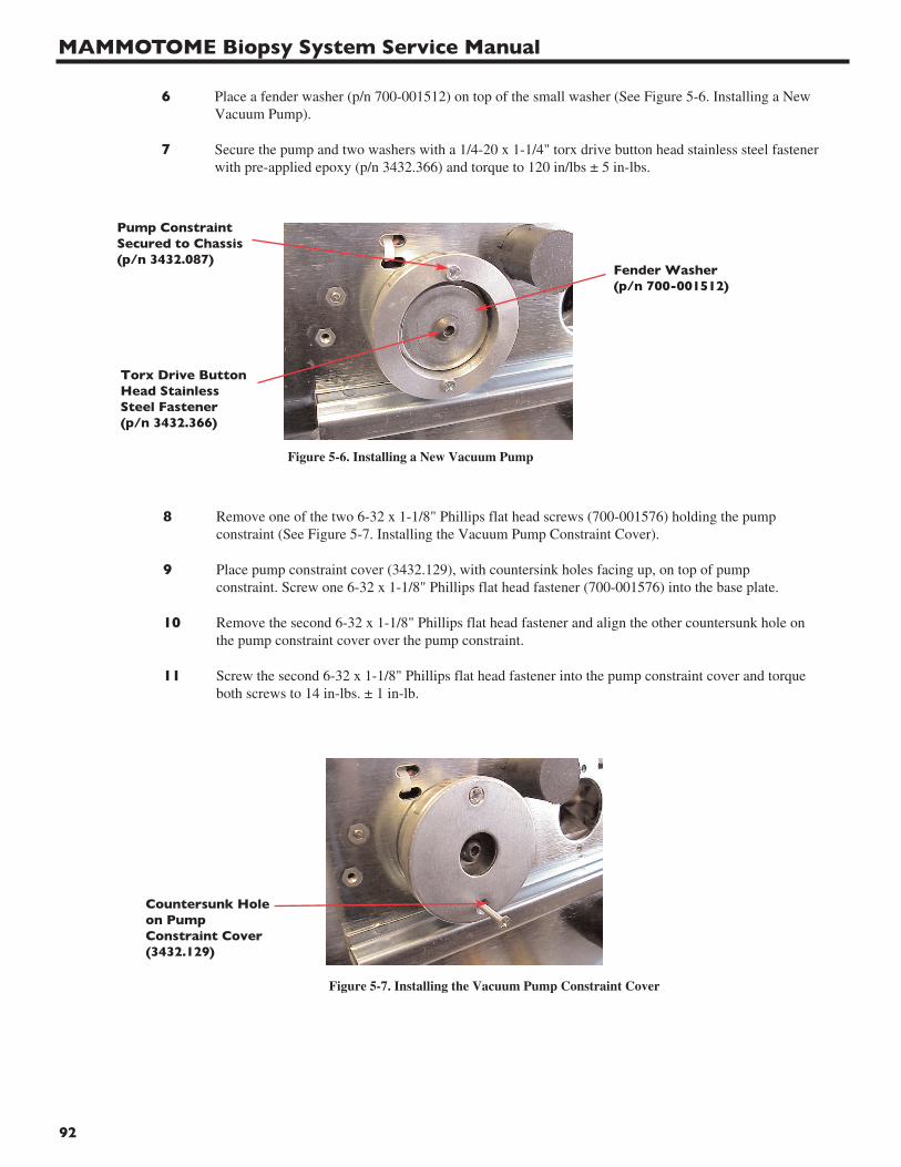
MAMMOTOME Biopsy System Service Manual
92
6 Place a fender washer (p/n 700-001512) on top of the small washer (See Figure 5-6. Installing a New Vacuum Pump).
7 Secure the pump and two washers with a 1/4-20 x 1-1/4" torx drive button head stainless steel fastener with pre-applied epoxy (p/n 3432.366) and torque to 120 in/lbs ± 5 in-lbs.
8 Remove one of the two 6-32 x 1-1/8" Phillips flat head screws (700-001576) holding the pump constraint (See Figure 5-7. Installing the Vacuum Pump Constraint Cover).
9 Place pump constraint cover (3432.129), with countersink holes facing up, on top of pump constraint. Screw one 6-32 x 1-1/8" Phillips flat head fastener (700-001576) into the base plate.
10 Remove the second 6-32 x 1-1/8" Phillips flat head fastener and align the other countersunk hole on the pump constraint cover over the pump constraint.
11 Screw the second 6-32 x 1-1/8" Phillips flat head fastener into the pump constraint cover and torque both screws to 14 in-lbs. ± 1 in-lb.
Pump ConstraintSecured to Chassis(p/n 3432.087)
Torx Drive ButtonHead StainlessSteel Fastener(p/n 3432.366)
Countersunk Holeon PumpConstraint Cover(3432.129)
Fender Washer(p/n 700-001512)
Figure 5-6. Installing a New Vacuum Pump
Figure 5-7. Installing the Vacuum Pump Constraint Cover
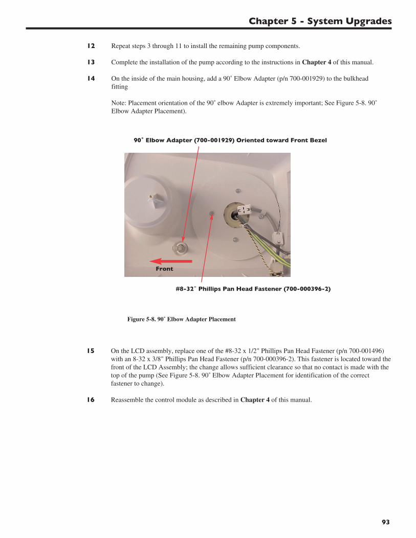
Chapter 5 - System Upgrades
93
12 Repeat steps 3 through 11 to install the remaining pump components.
13 Complete the installation of the pump according to the instructions in Chapter 4 of this manual.
14 On the inside of the main housing, add a 90˚ Elbow Adapter (p/n 700-001929) to the bulkhead fitting
Note: Placement orientation of the 90˚ elbow Adapter is extremely important; See Figure 5-8. 90˚ Elbow Adapter Placement).
15 On the LCD assembly, replace one of the #8-32 x 1/2" Phillips Pan Head Fastener (p/n 700-001496) with an 8-32 x 3/8" Phillips Pan Head Fastener (p/n 700-000396-2). This fastener is located toward thefront of the LCD Assembly; the change allows sufficient clearance so that no contact is made with the top of the pump (See Figure 5-8. 90˚ Elbow Adapter Placement for identification of the correct fastener to change).
16 Reassemble the control module as described in Chapter 4 of this manual.
#8-32" Phillips Pan Head Fastener (700-000396-2)
90˚ Elbow Adapter (700-001929) Oriented toward Front Bezel
Figure 5-8. 90˚ Elbow Adapter Placement
Front
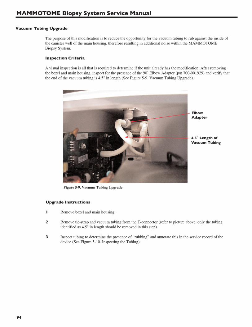
MAMMOTOME Biopsy System Service Manual
94
Vacuum Tubing Upgrade
The purpose of this modification is to reduce the opportunity for the vacuum tubing to rub against the inside of the canister well of the main housing, therefore resulting in additional noise within the MAMMOTOME Biopsy System.
Inspection Criteria
A visual inspection is all that is required to determine if the unit already has the modification. After removing the bezel and main housing, inspect for the presence of the 90˚ Elbow Adapter (p/n 700-001929) and verify thatthe end of the vacuum tubing is 4.5" in length (See Figure 5-9. Vacuum Tubing Upgrade).
Upgrade Instructions
1 Remove bezel and main housing.
2 Remove tie-strap and vacuum tubing from the T-connector (refer to picture above, only the tubing identified as 4.5" in length should be removed in this step).
3 Inspect tubing to determine the presence of “rubbing” and annotate this in the service record of the device (See Figure 5-10. Inspecting the Tubing).
ElbowAdapter
4.5" Length ofVacuum Tubing
Figure 5-9. Vacuum Tubing Upgrade
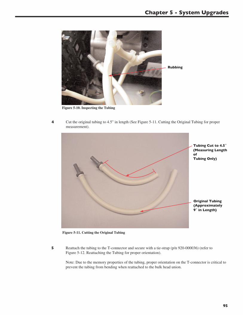
Chapter 5 - System Upgrades
95
4 Cut the original tubing to 4.5" in length (See Figure 5-11. Cutting the Original Tubing for proper measurement).
5 Reattach the tubing to the T-connector and secure with a tie-strap (p/n 920-000036) (refer to Figure 5-12. Reattaching the Tubing for proper orientation).
Note: Due to the memory properties of the tubing, proper orientation on the T-connector is critical to prevent the tubing from bending when reattached to the bulk head union.
Rubbing
Tubing Cut to 4.5"(Measuring LengthofTubing Only)
Original Tubing(Approximately9" in Length)
Figure 5-10. Inspecting the Tubing
Figure 5-11. Cutting the Original Tubing
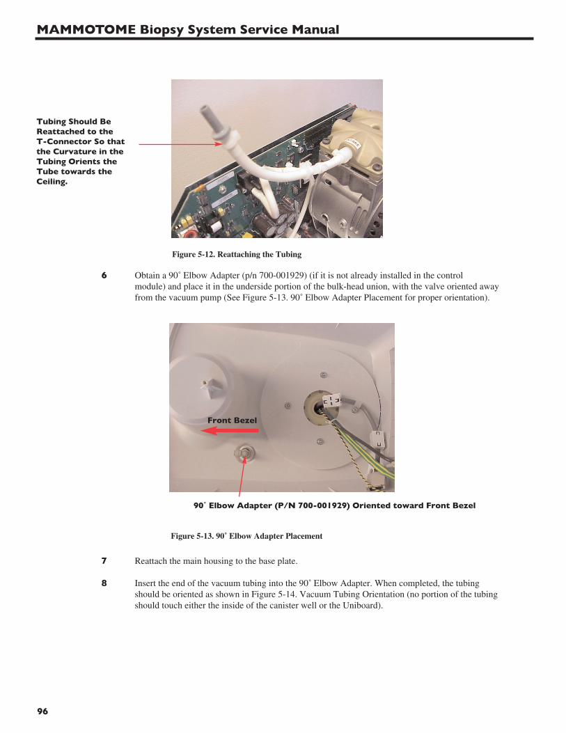
MAMMOTOME Biopsy System Service Manual
96
6 Obtain a 90˚ Elbow Adapter (p/n 700-001929) (if it is not already installed in the control module) and place it in the underside portion of the bulk-head union, with the valve oriented awayfrom the vacuum pump (See Figure 5-13. 90˚ Elbow Adapter Placement for proper orientation).
7 Reattach the main housing to the base plate.
8 Insert the end of the vacuum tubing into the 90˚ Elbow Adapter. When completed, the tubing should be oriented as shown in Figure 5-14. Vacuum Tubing Orientation (no portion of the tubing should touch either the inside of the canister well or the Uniboard).
Tubing Should BeReattached to the T-Connector So thatthe Curvature in theTubing Orients theTube towards theCeiling.
90˚ Elbow Adapter (P/N 700-001929) Oriented toward Front Bezel
Figure 5-12. Reattaching the Tubing
Figure 5-13. 90˚ Elbow Adapter Placement
Front Bezel
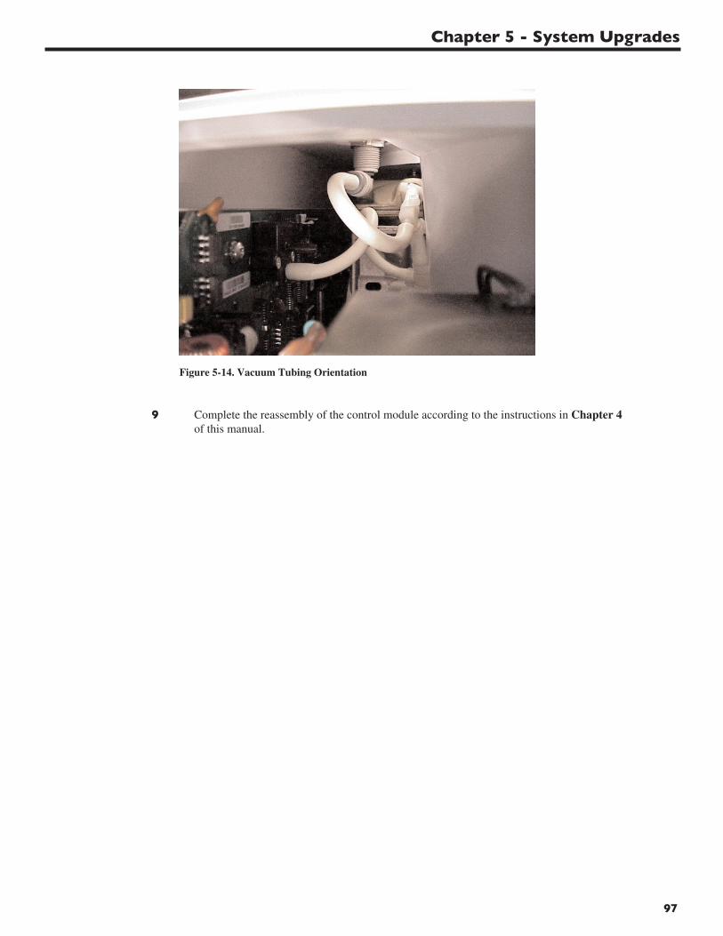
Chapter 5 - System Upgrades
97
9 Complete the reassembly of the control module according to the instructions in Chapter 4of this manual.
Figure 5-14. Vacuum Tubing Orientation
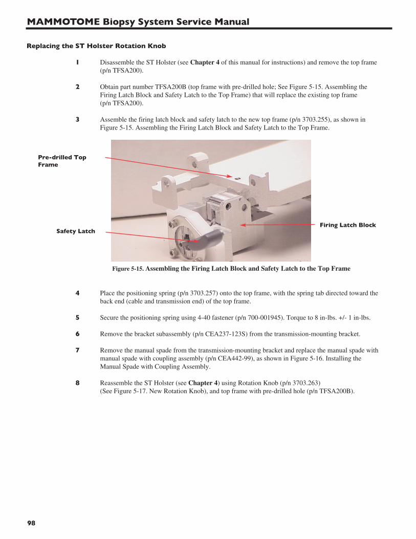
MAMMOTOME Biopsy System Service Manual
98
Replacing the ST Holster Rotation Knob
1 Disassemble the ST Holster (see Chapter 4 of this manual for instructions) and remove the top frame (p/n TFSA200).
2 Obtain part number TFSA200B (top frame with pre-drilled hole; See Figure 5-15. Assembling theFiring Latch Block and Safety Latch to the Top Frame) that will replace the existing top frame (p/n TFSA200).
3 Assemble the firing latch block and safety latch to the new top frame (p/n 3703.255), as shown in Figure 5-15. Assembling the Firing Latch Block and Safety Latch to the Top Frame.
4 Place the positioning spring (p/n 3703.257) onto the top frame, with the spring tab directed toward theback end (cable and transmission end) of the top frame.
5 Secure the positioning spring using 4-40 fastener (p/n 700-001945). Torque to 8 in-lbs. +/- 1 in-lbs.
6 Remove the bracket subassembly (p/n CEA237-123S) from the transmission-mounting bracket.
7 Remove the manual spade from the transmission-mounting bracket and replace the manual spade withmanual spade with coupling assembly (p/n CEA442-99), as shown in Figure 5-16. Installing theManual Spade with Coupling Assembly.
8 Reassemble the ST Holster (see Chapter 4) using Rotation Knob (p/n 3703.263) (See Figure 5-17. New Rotation Knob), and top frame with pre-drilled hole (p/n TFSA200B).
Pre-drilled TopFrame
Safety LatchFiring Latch Block
Figure 5-15. Assembling the Firing Latch Block and Safety Latch to the Top Frame
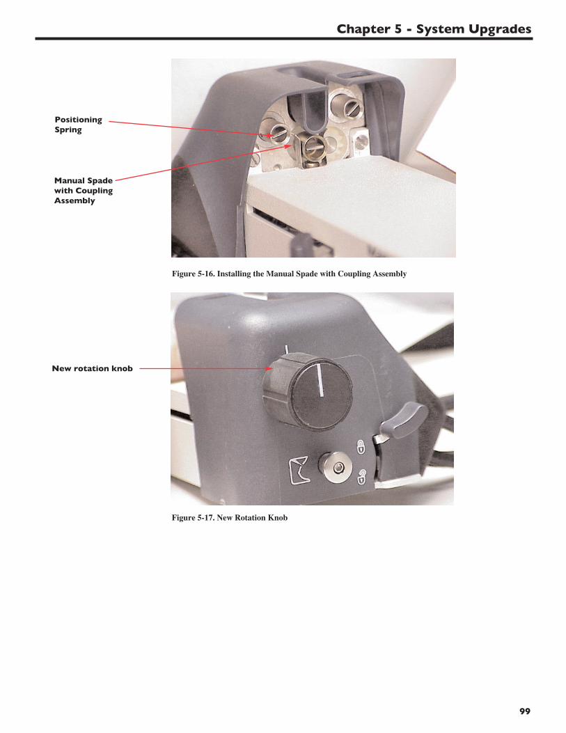
Chapter 5 - System Upgrades
99
New rotation knob
Manual Spadewith CouplingAssembly
Positioning Spring
Figure 5-16. Installing the Manual Spade with Coupling Assembly
Figure 5-17. New Rotation Knob

MAMMOTOME Biopsy System Service Manual
100
Coil Pin Replacement
Materials/Equipment Required
Part Description Old Part Number New Part Number
Manual Spade Assembly CEA442-99S CEA665-31S
Coiled Pin CLDP031X187MDPS CLDP047X187MCP
Port Shaft CEA237-707S CEA663-85S
Spur Gear A1N1-N32012-S CEA664-85S
Bracket Sub-Assembly CEA-237-123S CEA666-31S
Inspection Criteria/Upgrade Identification
• All ST Holsters with serial numbers of GST042479 and lower will require inspection for the upgrade.
• Each unit that is upgraded (S/N GST042479 and lower) will have an X scribed into the Bracket Sub-Assembly above the left spade lug to enable a visual inspection for the presence of the upgrade.
Upgrade Procedure
1 Disassemble the ST Holster, completing the steps up to and including removal of the shroud and bottom frame described in Chapter 4 of this manual.
2 Remove the e-clip that secures the existing spade assembly (p/n CEA442-99) to the bracket subassembly (p/n CEA237-123S)
3 Remove the existing spade assembly and replace it with manual spade assembly (p/n CEA665-31S), securing it in place with the e-clip and washer included with the assembly.
4 Place the port shaft in the Mammotome ST Holster Pin Assembly Fixture (installed in the Arbor Press), aligning the hole in the port shaft with the pin in the fixture
5 Position the coiled pin (p/n CLDP047X187MCP) on the top hole of the port shaft and lower the Arbor Press to secure the coiled pin in the machined hole of the port shaft.
6 On the blade side of the bracket subassembly, scribe an “X” above the left spade lug. This may be done with an engraving tool or a sharp object, as the metal is soft.
7 Reassemble the ST Holster using port shaft using new port shaft (p/n CEA663-85S), and new spur gear (p/n CEA664-85S)
Quality Assurance
Update Quality Assurance inspection criteria to include the inspection for the upgrade X above the left spade lug for all ST Holsters with a serial number of GST042479 and lower.
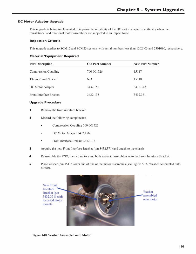
Chapter 5 - System Upgrades
101
DC Motor Adapter Upgrade
This upgrade is being implemented to improve the reliability of the DC motor adapter, specifically when thetranslational and rotational motor assemblies are subjected to an impact force.
Inspection Criteria
This upgrade applies to SCM12 and SCM23 systems with serial numbers less than 1202403 and 2301080, respectively.
Material/Equipment Required
Part Description Old Part Number New Part Number
Compression Coupling 700-001526 15117
13mm Round Spacer N/A 15118
DC Motor Adapter 3432.156 3432.372
Front Interface Bracket 3432.133 3432.371
Upgrade Procedure
1 Remove the front interface bracket.
2 Discard the following components:
• Compression Coupling 700-001526
• DC Motor Adapter 3432.156
• Front Interface Bracket 3432.133
3 Acquire the new Front Interface Bracket (p/n 3432.371) and attach to the chassis.
4 Reassemble the VSO, the two motors and both solenoid assemblies onto the Front Interface Bracket.
5 Place washer (p/n 15118) over end of one of the motor assemblies (see Figure 5-18. Washer Assembled onto Motor).
Figure 5-18. Washer Assembled onto Motor
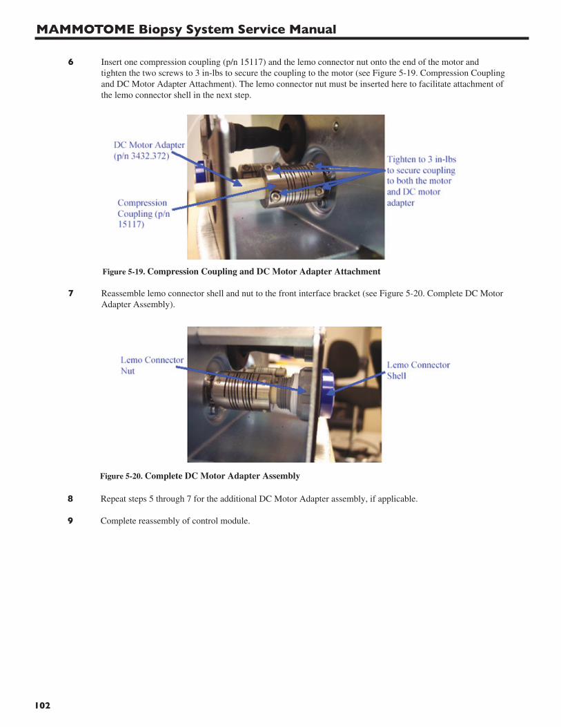
MAMMOTOME Biopsy System Service Manual
102
6 Insert one compression coupling (p/n 15117) and the lemo connector nut onto the end of the motor and tighten the two screws to 3 in-lbs to secure the coupling to the motor (see Figure 5-19. Compression Couplingand DC Motor Adapter Attachment). The lemo connector nut must be inserted here to facilitate attachment ofthe lemo connector shell in the next step.
Figure 5-19. Compression Coupling and DC Motor Adapter Attachment
7 Reassemble lemo connector shell and nut to the front interface bracket (see Figure 5-20. Complete DC Motor Adapter Assembly).
Figure 5-20. Complete DC Motor Adapter Assembly
8 Repeat steps 5 through 7 for the additional DC Motor Adapter assembly, if applicable.
9 Complete reassembly of control module.
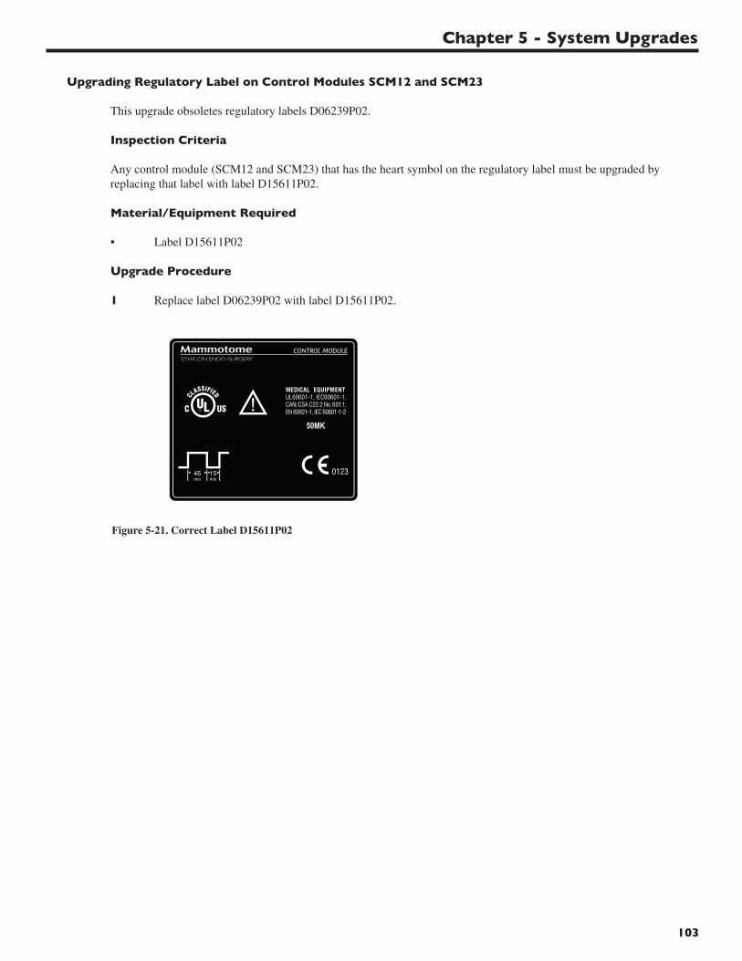
Chapter 5 - System Upgrades
103
Upgrading Regulatory Label on Control Modules SCM12 and SCM23
This upgrade obsoletes regulatory labels D06239P02.
Inspection Criteria
Any control module (SCM12 and SCM23) that has the heart symbol on the regulatory label must be upgraded by replacing that label with label D15611P02.
Material/Equipment Required
• Label D15611P02
Upgrade Procedure
1 Replace label D06239P02 with label D15611P02.
Figure 5-21. Correct Label D15611P02
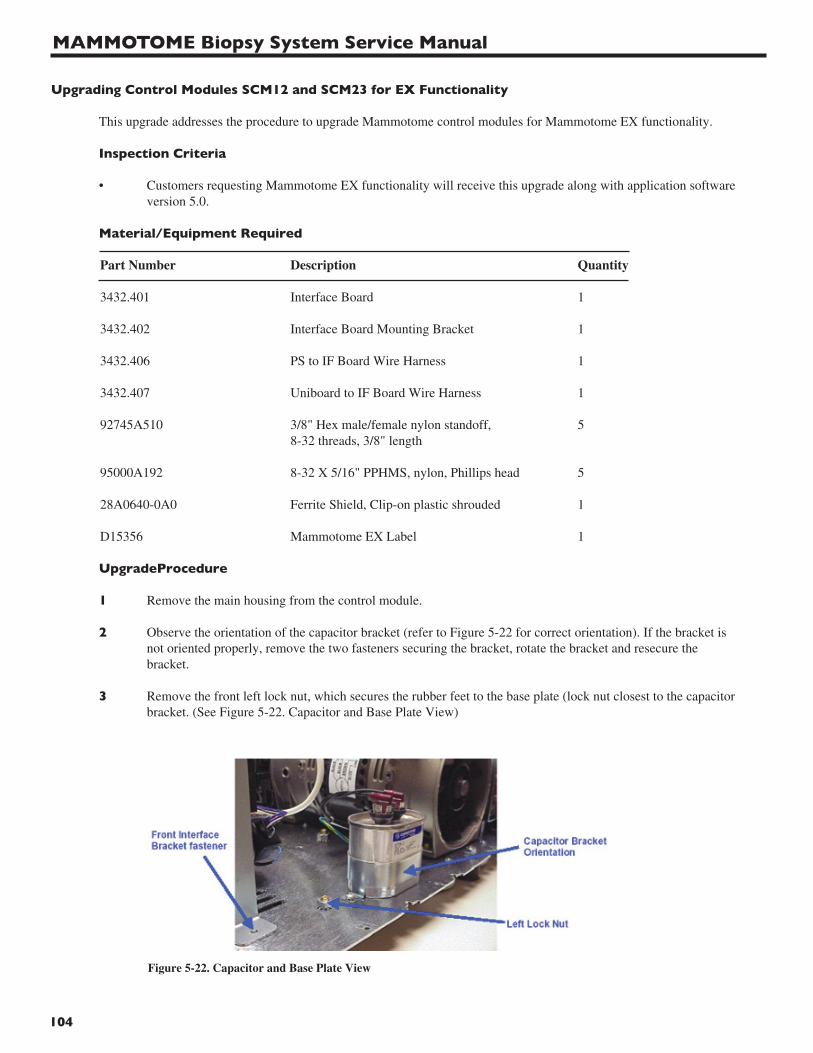
MAMMOTOME Biopsy System Service Manual
104
Upgrading Control Modules SCM12 and SCM23 for EX Functionality
This upgrade addresses the procedure to upgrade Mammotome control modules for Mammotome EX functionality.
Inspection Criteria
• Customers requesting Mammotome EX functionality will receive this upgrade along with application software version 5.0.
Material/Equipment Required
Part Number Description Quantity
3432.401 Interface Board 1
3432.402 Interface Board Mounting Bracket 1
3432.406 PS to IF Board Wire Harness 1
3432.407 Uniboard to IF Board Wire Harness 1
92745A510 3/8" Hex male/female nylon standoff, 58-32 threads, 3/8" length
95000A192 8-32 X 5/16" PPHMS, nylon, Phillips head 5
28A0640-0A0 Ferrite Shield, Clip-on plastic shrouded 1
D15356 Mammotome EX Label 1
UpgradeProcedure
1 Remove the main housing from the control module.
2 Observe the orientation of the capacitor bracket (refer to Figure 5-22 for correct orientation). If the bracket is not oriented properly, remove the two fasteners securing the bracket, rotate the bracket and resecure the bracket.
3 Remove the front left lock nut, which secures the rubber feet to the base plate (lock nut closest to the capacitor bracket. (See Figure 5-22. Capacitor and Base Plate View)
Figure 5-22. Capacitor and Base Plate View
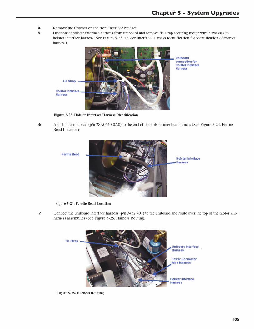
Chapter 5 - System Upgrades
105
4 Remove the fastener on the front interface bracket.5 Disconnect holster interface harness from uniboard and remove tie strap securing motor wire harnesses to
holster interface harness (See Figure 5-23 Holster Interface Harness Identification for identification of correct harness).
Figure 5-23. Holster Interface Harness Identification
6 Attach a ferrite bead (p/n 28A0640-0A0) to the end of the holster interface harness (See Figure 5-24. Ferrite Bead Location)
Figure 5-24. Ferrite Bead Location
7 Connect the uniboard interface harness (p/n 3432.407) to the uniboard and route over the top of the motor wire harness assemblies (See Figure 5-25. Harness Routing)
Figure 5-25. Harness Routing
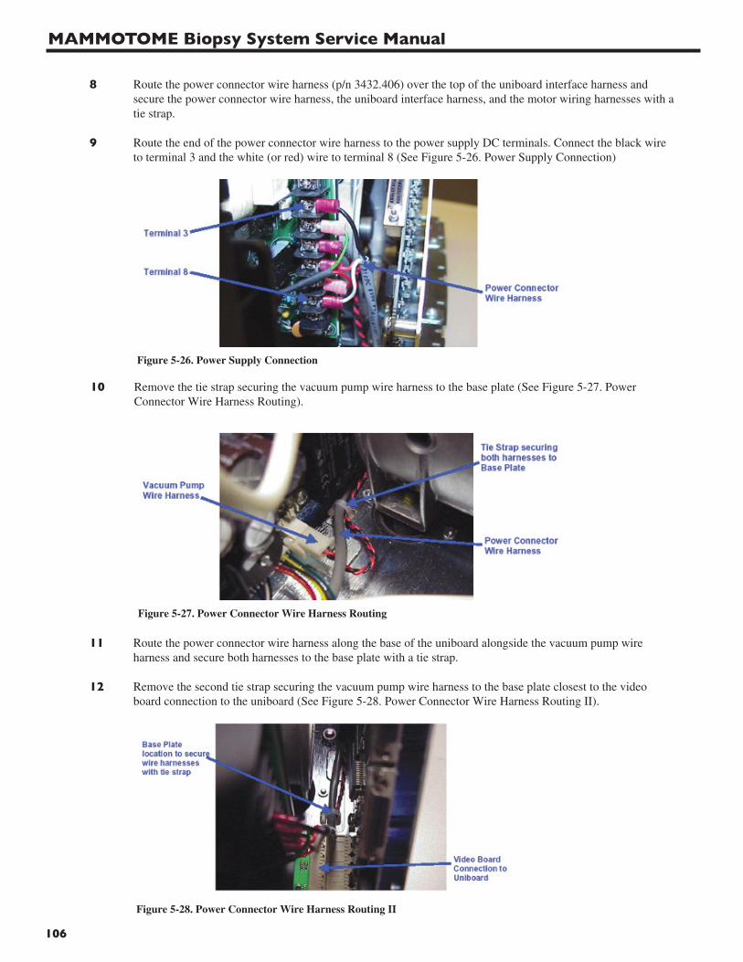
MAMMOTOME Biopsy System Service Manual
106
8 Route the power connector wire harness (p/n 3432.406) over the top of the uniboard interface harness and secure the power connector wire harness, the uniboard interface harness, and the motor wiring harnesses with a tie strap.
9 Route the end of the power connector wire harness to the power supply DC terminals. Connect the black wire to terminal 3 and the white (or red) wire to terminal 8 (See Figure 5-26. Power Supply Connection)
Figure 5-26. Power Supply Connection
10 Remove the tie strap securing the vacuum pump wire harness to the base plate (See Figure 5-27. Power Connector Wire Harness Routing).
Figure 5-27. Power Connector Wire Harness Routing
11 Route the power connector wire harness along the base of the uniboard alongside the vacuum pump wire harness and secure both harnesses to the base plate with a tie strap.
12 Remove the second tie strap securing the vacuum pump wire harness to the base plate closest to the video board connection to the uniboard (See Figure 5-28. Power Connector Wire Harness Routing II).
Figure 5-28. Power Connector Wire Harness Routing II
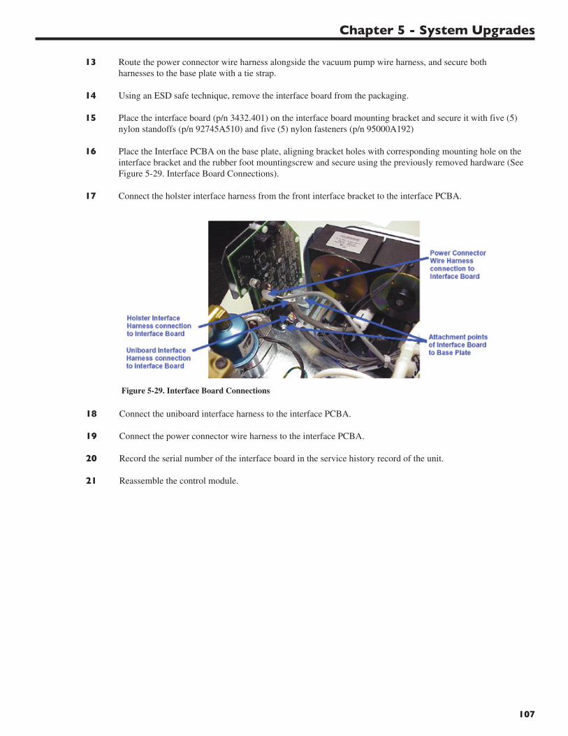
Chapter 5 - System Upgrades
107
13 Route the power connector wire harness alongside the vacuum pump wire harness, and secure both harnesses to the base plate with a tie strap.
14 Using an ESD safe technique, remove the interface board from the packaging.
15 Place the interface board (p/n 3432.401) on the interface board mounting bracket and secure it with five (5) nylon standoffs (p/n 92745A510) and five (5) nylon fasteners (p/n 95000A192)
16 Place the Interface PCBA on the base plate, aligning bracket holes with corresponding mounting hole on the interface bracket and the rubber foot mountingscrew and secure using the previously removed hardware (See Figure 5-29. Interface Board Connections).
17 Connect the holster interface harness from the front interface bracket to the interface PCBA.
Figure 5-29. Interface Board Connections
18 Connect the uniboard interface harness to the interface PCBA.
19 Connect the power connector wire harness to the interface PCBA.
20 Record the serial number of the interface board in the service history record of the unit.
21 Reassemble the control module.
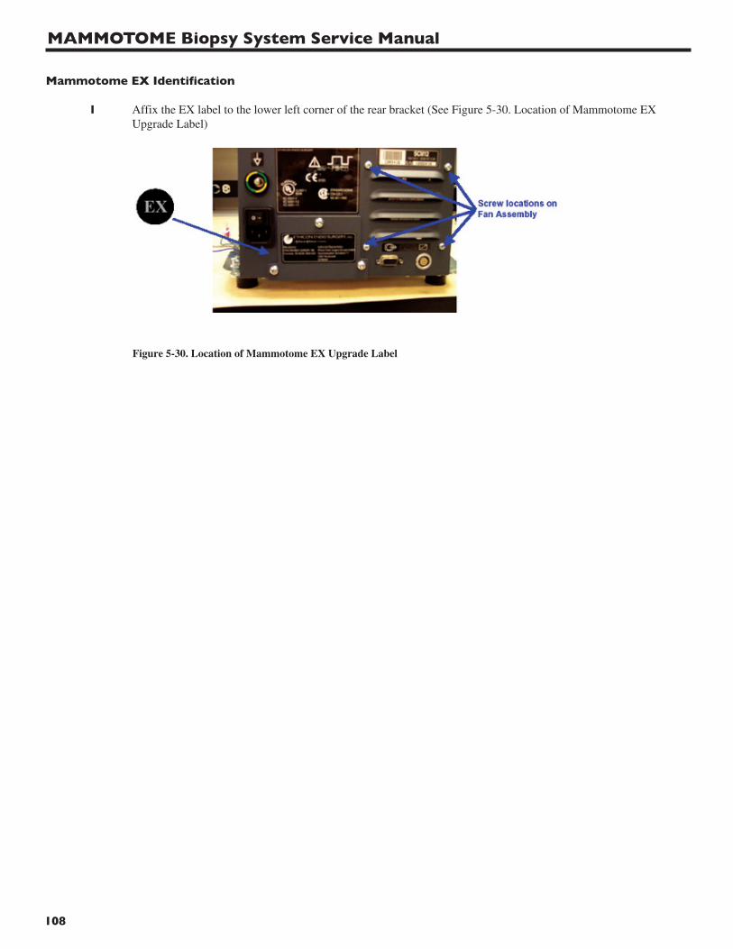
MAMMOTOME Biopsy System Service Manual
108
Mammotome EX Identification
1 Affix the EX label to the lower left corner of the rear bracket (See Figure 5-30. Location of Mammotome EX Upgrade Label)
Figure 5-30. Location of Mammotome EX Upgrade Label
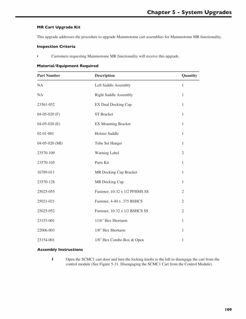
Chapter 5 - System Upgrades
109
MR Cart Upgrade Kit
This upgrade addresses the procedure to upgrade Mammotome cart assemblies for Mammotome MR functionality.
Inspection Criteria
• Customers requesting Mammotome MR functionality will receive this upgrade.
Material/Equipment Required
Part Number Description Quantity
NA Left Saddle Assembly 1
NA Right Saddle Assembly 1
23561-052 EX Dual Docking Cup 1
04-05-020 (F) ST Bracket 1
04-05-020 (E) EX Mounting Bracket 1
02-01-001 Holster Saddle 1
04-05-020 (MI) Tube Set Hanger 1
23570-109 Warning Label 2
23570-105 Parts Kit 1
16789-011 MR Docking Cup Bracket 1
23570-128 MR Docking Cup 1
25025-055 Fastener, 10-32 x 1/2 PFHMS SS 2
25021-021 Fastener, 4-40 x .375 BSHCS 2
25025-052 Fastener, 10-32 x 1/2 BSHCS SS 2
23153-001 1/16" Hex Shortarm 1
22006-003 1/8" Hex Shortarm 1
23154-001 1/8" Hex Combo Box & Open 1
Assembly Instructions
1 Open the SCMC1 cart door and turn the locking knobs to the left to disengage the cart from the control module (See Figure 5-31. Disengaging the SCMC1 Cart from the Control Module).
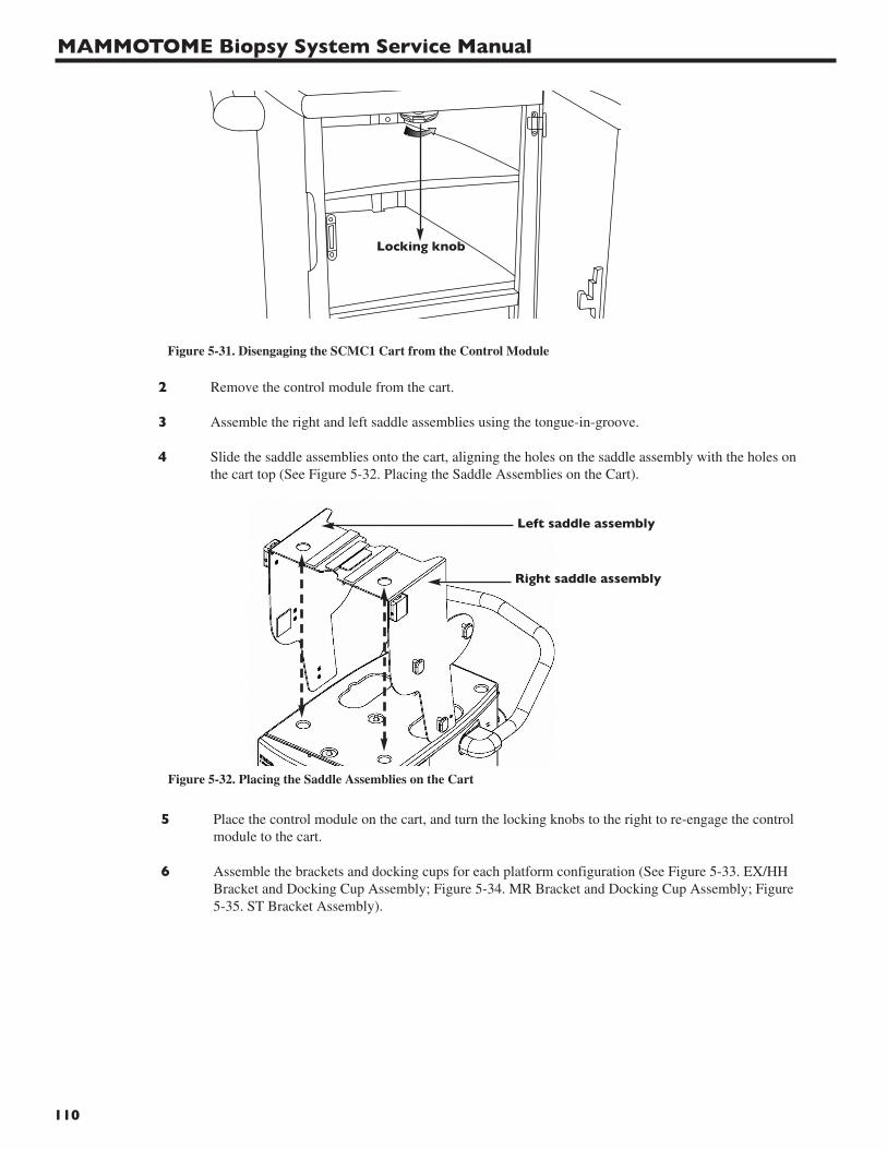
MAMMOTOME Biopsy System Service Manual
110
2 Remove the control module from the cart.
3 Assemble the right and left saddle assemblies using the tongue-in-groove.
4 Slide the saddle assemblies onto the cart, aligning the holes on the saddle assembly with the holes on the cart top (See Figure 5-32. Placing the Saddle Assemblies on the Cart).
Figure 5-31. Disengaging the SCMC1 Cart from the Control Module
Locking knob
Figure 5-32. Placing the Saddle Assemblies on the Cart
5 Place the control module on the cart, and turn the locking knobs to the right to re-engage the control module to the cart.
6 Assemble the brackets and docking cups for each platform configuration (See Figure 5-33. EX/HH Bracket and Docking Cup Assembly; Figure 5-34. MR Bracket and Docking Cup Assembly; Figure 5-35. ST Bracket Assembly).
Left saddle assembly
Right saddle assembly
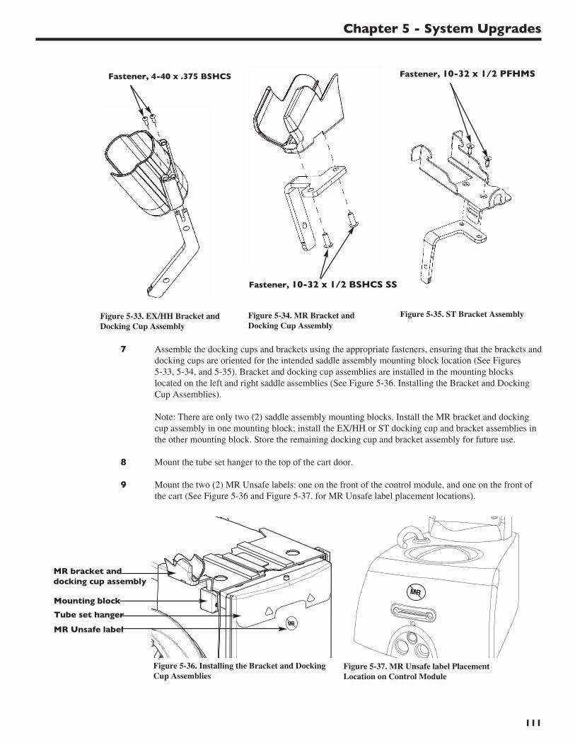
Chapter 5 - System Upgrades
111
Figure 5-33. EX/HH Bracket andDocking Cup Assembly
Figure 5-34. MR Bracket andDocking Cup Assembly
Figure 5-35. ST Bracket Assembly
7 Assemble the docking cups and brackets using the appropriate fasteners, ensuring that the brackets anddocking cups are oriented for the intended saddle assembly mounting block location (See Figures 5-33, 5-34, and 5-35). Bracket and docking cup assemblies are installed in the mounting blocks located on the left and right saddle assemblies (See Figure 5-36. Installing the Bracket and Docking Cup Assemblies).
Note: There are only two (2) saddle assembly mounting blocks. Install the MR bracket and docking cup assembly in one mounting block; install the EX/HH or ST docking cup and bracket assemblies in the other mounting block. Store the remaining docking cup and bracket assembly for future use.
8 Mount the tube set hanger to the top of the cart door.
9 Mount the two (2) MR Unsafe labels: one on the front of the control module, and one on the front of the cart (See Figure 5-36 and Figure 5-37. for MR Unsafe label placement locations).
MR
MR
Fastener, 4-40 x .375 BSHCS Fastener, 10-32 x 1/2 PFHMS
Fastener, 10-32 x 1/2 BSHCS SS
MR bracket anddocking cup assembly
Mounting block
Tube set hanger
MR Unsafe label
Figure 5-36. Installing the Bracket and DockingCup Assemblies
Figure 5-37. MR Unsafe label PlacementLocation on Control Module

MAMMOTOME Biopsy System Service Manual
112
Chapter 6 - Electrical Safety Testing
113
IntroductionElectrical safety testing is required whenever the ground is disconnected from the MAMMOTOME System and/or an electrical/mechanical component is removed or replaced.
Required Equipment
• Dielectric Strength Tester• Continuity Tester
Electrical Safety Tests
Mains to Earth Ground Test Procedure
1 Connect the High Voltage port of the tester to the mains of the unit under test.
2 Connect the Return port of the tester to the ground lug of the unit under test.
3 Set the tester to 1200AC volts (1834 VAC for SCM23) for one second with a one-second ramp.
4 The current limit should be set to 10mA (15mA for SCM23).
5 Update Figure 6-1. Electrical Safety Test Results, with test results.
Mains to Patient Test Procedure
1 Leave the High Voltage port of the tester connected to the mains of the unit under test.
2 Connect the Return port of the tester to all pins of the holster electrical connector.
3 Set the tester to 3000AC volts for one second with a one-second ramp.
4 The current limit should be set for 20mA.
5 Update Figure 6-1. Electrical Safety Test Results, with test results.
Ground Continuity Test
1 Connect the unit under test to the electrical receptacle of the tester.
2 Connect the continuity port of the tester to the ground lug of the unit under test.
3 Set the tester to a limit of 30A and 0.1 Ω.
4 Update Figure 6-1. Electrical Safety Test Results, with test results.

MAMMOTOME Biopsy System Service Manual
114
Figure 6-1. Electrical Safety Test Results
Procedure Test Specification Tested Value Pass/Fail
Mains to Earth Ground Test < 10mA
Mains to Patient Test < 20mA
Ground Continuity Test < 0.1 Ω
Tested By (Print name): __________________________________________
Signature: __________________________________________ Date: __________________
Chapter 7 - Warranty
115
Ethicon Endo-Surgery, Inc. warrants this product to be free from defects in material and workmanship undernormal use and preventive maintenance for the respective warranty period shown below. Ethicon Endo-Surgery Inc.’s obligation under this warranty is limited to the repair or replacement, at its option, of anyproduct, or part thereof, which has been returned to Ethicon Endo-Surgery, Inc. or its Distributor within theapplicable time period shown below and which examination disclosed, to Ethicon Endo-Surgery, Inc.’ssatisfaction, to be defective. This warranty does not apply to any product, or part thereof, that has been: (1)adversely affected due to use with devices manufactured or distributed by parties not authorized by EthiconEndo-Surgery, Inc. (2) repaired or altered outside Ethicon Endo-Surgery, Inc.’s factory in a way so as to, inEthicon Endo-Surgery, Inc.’s judgement, affect its stability or reliability, (3) subjected to improper use,negligence or accident, or (4) used other than in accordance with the design and use parameters, instructionsand guidelines for the product or with functional, operational or environmental standards for similar productsgenerally accepted in the industry.
Ethicon Endo-Surgery, Inc.’s products are warranted for the following periods after delivery to the originalpurchaser:
ST Holster One (1) Year, Parts and LaborHH Holster One (1) Year, Parts and LaborEX Holster One (1) Year, Parts and LaborMR Holster One (1) Year, Parts and LaborMR Interlock System One (1) Year, Parts and LaborControl Module One (1) Year, Parts and LaborFootswitch One (1) Year, Parts and LaborSupport Arm One (1) Year, Parts and LaborCart and Cart Upgrade Kit One (1) Year, Parts and LaborSoftware Package One (1) Year, Parts and LaborRemote Keypad One (1) Year, Parts and Labor
UNLESS SUPERCEDED BY APPLICABLE LOCAL LAW, THIS WARRANTY IS IN LIEU OF ALLOTHER WARRANTIES, EXPRESS OR IMPLIED, INCLUDING THE WARRANTIES OFMERCHANTABILITY AND FITNESS FOR A PARTICULAR PURPOSE, AND OF ALL OTHEROBLIGATIONS OR LIABILITIES ON THE PART OF ETHICON ENDO-SURGERY, INC. AND IS APURCHASER’S EXCLUSIVE REMEDY. IN NO EVENT SHALL ETHICON ENDO-SURGERY, INC. BELIABLE FOR SPECIAL, INCIDENTAL OR CONSEQUENTIAL DAMAGES INCLUDING, WITHOUTLIMITATION, DAMAGES RESULTING FROM LOSS OF USE, PROFITS, BUSINESS OR GOODWILLOTHER THAN AS EXPRESSLY PROVIDED BY A SPECIFIC LAW. Ethicon Endo-Surgery, Inc. neitherassumes nor authorizes any other person to assume for it any other liability in connection with the sale or useof any of Ethicon Endo-Surgery, Inc. products. There are no warranties that extend beyond the terms hereof.
Ethicon Endo-Surgery, Inc. reserves the right to make changes to products built and/or sold by them at anytime without incurring any obligation to make the same or similar changes on products previously built and/orsold by them.
Caution: Federal (USA) law restricts this device to sale by or on the order of a physician.

REF
SCM12 HH11BEX MUPG4SCM23 HH8BEXHHHC1 MHH11STHC1 MHH11BHHEX MHH14SCMH1 MHH8SCMH2 MST11SCMH3 MST11BSCMS1 MST14SCMS2 MST8SCMA1 MRH1SCMSW4 MRLB1SCMSW5 SCMSW6MFSW1 SCMC1MKEY1 SCMC3
Johnson & Johnson AGCH-8957 SpreitenbachSWITZERLAND
Ethicon Endo-Surgery (Europe) GmbHHummelsbuetteler Steindamm 7122851 NorderstedtGermany
Ethicon Endo-Surgery, Inc.Cincinnati, OH 45242-2839 USA 1-800-USE-ENDO
2007Guaynabo, Puerto Rico 00969 USA P43538P04
2008
P43538P04