mmaaiinntteennaannccee hhaannddbbooookk oonn...
TRANSCRIPT

Hkkjr ljdkj GOVERNMENT OF INDIA
jsy ea=ky; MINISTRY OF RAILWAYS
egkjktiqj, Xokfy;j & 474 005
Maharajpur, GWALIOR - 474 005
CAMTECH/E/14-15/3 Loco Transformer/1.0
March, 2015
dsoy dk;Zky;hu mi;ksx gsrq
(For Official Use Only)
MMaaiinntteennaannccee HHaannddbbooookk oonn
TTrraannssffoorrmmeerr ooff 33 PPhhaassee EElleeccttrriicc LLooccoommoottiivvee
END USER: Loco Maintenance Staff

MMaaiinntteennaannccee HHaannddbbooookk oonn
TTrraannssffoorrmmeerr ooff 33 PPhhaassee EElleeccttrriicc LLooccoommoottiivvee
QUALITY POLICY
“To develop safe, modern and cost
effective Railway Technology
complying with Statutory and
Regulatory requirements, through
excellence in Research, Designs and
Standards and Continual
improvements in Quality
Management System to cater to
growing demand of passenger and
freight traffic on the railways”.

FOREWORD
Emerging technological changes require dissemination of new technology and
induction of new maintenance practices. The three phase electric locos were inducted
quite some time back in Railway system but still there is no maintenance handbook
on transformer. The transformer is an important equipment of electric loco (like heart
in human body). The transformer needs proper maintenance for trouble free and
reliable operation of locomotives.
CAMTECH has prepared this handbook on “Maintenance of Transformer of
Three Phase Electric Locomotives” with an objective to provide comprehensive
information on the technical as well as maintenance aspects of the transformer.
I hope this handbook prove to be useful for the field staff engaged in the
maintenance of three phase electric locomotives and its transformer.
CAMTECH, Gwalior A.R.Tupe
Date: 26th
March, 2015 Executive Director


PREFACE
Transformer is an important equipment of three phase electric locomotives.
Proper upkeep of transformer is necessary to ensure trouble free operation of three
phase electric locomotives.
This handbook on “Maintenance of Transformer” of 3 phase electric
locomotive has been prepared by CAMTECH with the objective of making our
maintenance personnel aware of correct maintenance and overhaul techniques to be
adopted in the field. This handbook covers brief technical details, maintenance
practices, testing along with testing instruments required. This also covers condition
monitoring of transformer oil and model questions on the subject.
It is clarified that this handbook does not supersede any existing
provisions/guidelines laid down by Railway Board, RDSO or OEM. The handbook is
only for guidance and it is not a statutory document.
I am sincerely thankful to all field personnel who helped us in preparing this
handbook.
Technology up-gradation learning is a continuous process. Please feel free to
write tour for any addition/ modification in this handbook. We shall highly appreciate
your contribution in this direction.
CAMTECH, Gwalior Peeyoosh Gupta
Date: 26th
March, 2015 Director/ Electrical


CONTENTS
Chapter No. Description Page No.
Foreword iii
Preface iv
Contents v
Correction Slip vii
1. GENERAL 01
1.1 Introductions 01
1.2 Transformer Working Principle 03
1.2.1 EMF Equation of Transformer 04
1.3 Description of Three Phase Loco Transformer 04
1.3.1 Transformer Cooling 04
1.4 Different Parts of Transformer 07
1.5 Technical Data of Electric Loco Transformer 10
1.6 Transport of Transformer 11
1.6.1 Lifting of the Transformer 11
1.6.2 Supporting the Transformer on a Point 12
1.7 Storage of Transformer 12
1.7.1 Maintenance During Storage 13
1.9 Factors Affecting Life of Transformer 13 2. MAINTENANCE 15
2.1 Periodic Maintenance Schedules 15
2.2 Trip Inspection 16
2.3 Oil Circulating Pumps (SR & TFP) IA, IB 17
2.4 Main Transformer IC Schedule 18
2.5 Main Transformer (AOH) Schedule 19
2.6 Main Transformer (IOH) Schedule 20
2.7 Main Transformer POH Schedule 21
2.7.1 Painting Procedure 22
2.8 Procedure for Replacement of Bushings 22
2.9 Transformer Oil Check 23

Chapter No. Description Page No.
2.10 Testing of Loco Transformer 24
2.10.1 Tests 24
2.11 Testing Equipment 25
2.12 Installation of the Transformer on Locomotive 26
2.13 Check Points While Maintenance 29
2.14 Transformer Oil 31
2.14.1 Oil Specification 31
2.14.2 Purification of Transformer Oil 32
2.12.3 Condition monitoring of Transformer by Dissolved Gas Analysis 34
3. MODEL QUESTION 39
ANSWERS 45
An Approach to Equipment Failure Investigation 46 ANNEXURE – I - Reliability Action Plan (RAP) 47

ISSUE OF CORRECTION SLIPS
The correction slips to be issued in future for this handbook will be numbered as
follows :
CAMTECH/E/14-15/3 Loco Transformer/C.S. # XX date---------
Where “XX” is the serial number of the concerned correction slip (starting from 01
onwards).
CORRECTION SLIPS ISSUED
Sr. No. Date of issue Page no. and Item
no. modified
Remarks


CAMTECH/E/14-15/3 Loco Transformer/1.0
Maintenance Handbook on Transformer of 3 Phase Electric Locomotives March, 2015
1
CHAPTER 1
GENERAL
1.1 INTRODUCTION
The transformer is a static device, which transforms power from one AC circuit to
another AC circuit at same frequency but having different characteristics. These circuits are
conductively disjointed but magnetically coupled by a common time varying magnetic field.
It can raise or lower the voltage with a corresponding decrease or increase in current.
In all the electric locomotives, limiting the value of current during starting, speed
control is achieved by supply of variable voltage to the traction motors. This variation of
applied voltage can be carried out easily by the use of transformer along with Static
Convertor provided in the locomotive.
The windings which form the electrical circuit must fulfill certain basic
requirements, particularly the di-electric, thermal and mechanical stresses imposed on it
during testing as well as in service and cater for over loads under adverse conditions.
The WAG9 transformer unit consists of the main transformer active part and two
different types of reactors, hosed in a tank.
The main transformer converts the overhead line voltage (25 kV) to the lower
operating voltages for:
traction power supply 1268V
auxiliary 1kV
The main transformer is integrated into the traction circuit between overhead line
and rail return line.
The primary current line flows from the pantograph via roof line, vacuum circuit
breaker, the roof bushing into the primary winding of the main transformer. It then flows
back to the rail via the earth return brushes on four of the six axles. And WAP5, WAP7
transformer has total load winding in addition toWAG9 transformer.
Figure 1.1 Three Phase Loco Transformer

CAMTECH/E/14-15/3 Loco Transformer/1.0
March, 2015 Maintenance Handbook on Transformer of 3 Phase Electric Locomotives
2
Figure 1.2 Schematic Diagram of Power Circuit of 3 Phase Loco (WAG 9 , WAG 7)

CAMTECH/E/14-15/3 Loco Transformer/1.0
Maintenance Handbook on Transformer of 3 Phase Electric Locomotives March, 2015
3
1.2 TRANSFORMER WORKING PRINCIPLE
In general principle of working of a transformer can be expressed on the basis of law
of electromagnetic induction as following:
a. When a conductor cuts the magnetic flux or magnetic flux cut the conductor, an emf
is induced in the conductor.
b. The magnitude of this emf is proportional to the rate of change of flux.
E = -d/dt
Where, E = emf
= flux
Kinds of emf
The emf may be induced by two ways
i. Dynamically induced emf
ii. Statically induced emf.
a. Mutually induced emf
b. Self induced emf
An emf induced in a coil due to variation of flux in another coil placed near to first is
called mutually induced emf.
The emf induced in a coil due to change of its own flux linked with it is called self-
induced emf. (In case of autotransformer)
In its simplest form, a transformer consists of two conducting coils. The primary is
the winding which receives electric power, and the secondary is one which delivers the
electric power. These coils are wound on a laminated core of magnetic material.
The physical basis of a transformer is mutual induction between two circuits linked
by a common magnetic flux through a path of low reluctance as shown in fig.1.2
The two coils possesses high mutual inductance. If one coil is connected to a source
of alternating voltage, an alternating flux is set up in the laminated core, most of which is
linked up with the other coil in which it produces mutually induced emf i.e.
E = M di/dt
If the second circuit is closed, a current flows in it and so electric energy is
transferred (entirely magnetically) from first coil (primary winding) to the second coil
(secondary winding).
PRIMARY
LAMINATED CORE
SECONDARY
Figure 1.3 Ideal Transformer

CAMTECH/E/14-15/3 Loco Transformer/1.0
March, 2015 Maintenance Handbook on Transformer of 3 Phase Electric Locomotives
4
1.2.1 EMF Equation of Transformer
Let, N1 = Number of turns in primary.
N2 = Number of turns in secondary.
m = Maximum flux in the core in webres.
f = Frequency of AC input in Hz.
v1 = Instantaneous value of applied voltage in primary winding in volts.
The instantaneous value of counter electromotive force e1, can be expressed as
e1 = - N1 d/dt volt
The counter emf e1 is equal and opposite to applied voltage v1 i.e.
v1 = N1 d/dt volt
rms value of emf induced in primary
E1 = 4.44 f N1 m
Similarly, rms value of emf induced in secondary
E2 = 4.44 f N2 m
In an ideal transformer
V1 = E1 & V2 = E2
Where V2 is the secondary terminal voltage
With the above expressions we get
E2/ E1 = N2/ N1 = K
Where K is known as voltage transformation ratio.
(a) If N2 > N1 i.e. K > 1 then the transformer is called step up transformer.
(b) If N2 < N1 i.e. K < 1 then the transformer is called step down transformer.
1.3 DESCRIPTION OF THREE PHASE LOCO TRANSFORMER & ITS PARTS
Each loco requires one transformer for feeding supply to traction converters/ traction
motors, to auxiliary converter for supplying to auxiliary machines and to supply Hotel load
of train. This transformer will consist of Primary winding, 04 Traction windings, Auxiliary
winding (BUR) and Hotel Load winding. In addition, it has a FILTER winding which is
connected on locomotive to passive filter.
The transformer tank also contains 02 series resonant chokes (one for each
converter) & 03 Auxiliary Converter double chokes (one for each of the 03 auxiliary
converters).
1.3.1 Transformer cooling
Transformer is oil cooled and external cooling of the oil is designed with two
independent oil circuits with cooling units located within the machine room of locomotives.
However, the cooling units / circuit component do not form part of transformer supply.

CAMTECH/E/14-15/3 Loco Transformer/1.0
Maintenance Handbook on Transformer of 3 Phase Electric Locomotives March, 2015
5
Figure 1.4 Cooling Arrangement
Figure 1.5 Layout of Winding in Transformer Tank

CAMTECH/E/14-15/3 Loco Transformer/1.0
March, 2015 Maintenance Handbook on Transformer of 3 Phase Electric Locomotives
6
Figure 1.6 Three phase loco transformer winding diagram

CAMTECH/E/14-15/3 Loco Transformer/1.0
Maintenance Handbook on Transformer of 3 Phase Electric Locomotives March, 2015
7
1.4 DIFFERENT PARTS OF TRANSFORMER
i. Transformer tank fastening
Material : Aluminium
Colour : RAL-7009stain
Weight : 966 kg with lid
Identity No. : HSTN 424007
Figure 1.7 Transformer Tank Fastening
ii. Transformer main winding
Identity No. : HSTN 424337
Make : ABB Badodara, BHEL Jhansi,
CGL Mandideep Bhopal,
EMCO Thane Mumbai,
High volt electrical Ltd Mumbai,
Figure 1.8 Transformer main Winding
iii. SOD Winding
Identity No. : HSTN 424005
Make ABB Badodara, BHEL Jhansi,
CGL Mandideep Bhopal, EMCO Thane Mumbai,
High volt electrical Ltd Mumbai,
Figure 1.9 SOD Winding
iv. GOD Winding
Identity No. : HSTN 424006
Make ABB Badodara, BHEL Jhansi, CGL Mandideep Bhopal,
EMCO Thane Mumbai,
High volt electrical Ltd Mumbai,
Figure 1.10 GOD Winding

CAMTECH/E/14-15/3 Loco Transformer/1.0
March, 2015 Maintenance Handbook on Transformer of 3 Phase Electric Locomotives
8
v. Transformer Bushing
Identity No. DT 1/250 : HSTN 310500
DT 1/630 : HSTN 310501
DT 1/1000 : HSTN 310502 DT 1/2000 : HSTN 310503
DT 1/3150 : HSTN 310504
Figure 1.11 Transformer Bushing
vi. High Voltage Bushing
Identity No. : HSTN 420783P0001
Technical Data: 18/30 kV, 800A
Supplier : Elasti mold or RDSO approved
Figure 1.12 High Voltage Bushing
vii. Temperature Sensor (Thermometer)
Identity No. : HSTN 424136P0001
Technical Data : PT-100 Supplier : JUMO Stafa or RDSO approved
Figure 1.13 Temperature Sensor
viii. Overflow Valve Identity No. : HSTN 4/12/0144R
Pressure setting : 0.8 bar
Supplier : Millen Engineer or RDSO approved
Figure 1.14 Overflow Valve
ix. Transformer Main Valve
Identity No. : HSTN 4274037P0001
Technical Data : NW80 ND6 Supplier : Fatco or RDSO approved
Figure 1.15 Transformer main Valve

CAMTECH/E/14-15/3 Loco Transformer/1.0
Maintenance Handbook on Transformer of 3 Phase Electric Locomotives March, 2015
9
x. Slide of oil intake and drainage Identity No. : HSTN 422368P0001
Pressure setting : NW32/25
Supplier : Hofiman or RDSO approved
Figure 1.16 Slide of oil intake and drainage
xi Two conservator tanks including - Air dehumidifier including valve -Oil level gauge
Identity No. : HSTN Material : Aluminium
Colour : RAl 7030 stain
Volume : 137DMQ
Figure 1.17 Conservation Tanks
xii. Breather
Identity No. : HSTN 422029P0001
Technical Data : EM3MA Supplier : Yogya or RDSO approved
Figure 1.18 Breather
The special features of the transformer are :-
• Transformer is mounted under slung on under frame
• Transformer is designed for feeding GTO/IGBT based Power and Auxiliary converter
load.
• Very high impedance between primary & traction windings
• 100% de-couplings between windings
• Use of continuous transposed conductor for windings
• Use of disc construction of windings
• Transformer and conservator tank of Aluminum Alloy
• Rapid action coupling between transformer and conservators in oil circuit

CAMTECH/E/14-15/3 Loco Transformer/1.0
March, 2015 Maintenance Handbook on Transformer of 3 Phase Electric Locomotives
10
1.4 TECHNICAL DATA OF 3 PHASE ELECTRIC LOCO TRANSFORMERS (WAP5, WAP7 & WAG9)
Common Ratings for WAG9, WAP5 & WAP7 Loco Transformers
Rated voltage
Normal
Maximum
Minimum
25.0 kV
30.0 kV
17.5 kV
Frequency 50Hz ± 6 %
Cooling medium Inhibited transformer oil to IEC–296/ IS-12463
Series Resonant Choke (2SOD 240)
Inductance 0.551 mH (± 15 %), Liner to Ipeak = 1391A
Thermal current Ith 984A
Resonant frequency 100Hz
Voltage stress between terminals to earth Nominal 482 Vac , Max. 3471 V
Auxiliary Converter Choke (6GOD 120)
Inductance per PUR - choke
0A 30 mH
120A 30 mH
155A 26 mH
190A 20 mH
Frequency 100 hz
Current Rated 155A, Max. 190A
Ripple Nominal 38.6%, Max. 50.2%
Voltage to earth Rated 1153 V, Max. 2000 V
Ratings for WAG9 loco transformer
Winding Power (kVA) Voltage Current
HV 6531 25000 261.25
Traction 4 x 1449 4 x 1269 4 x 1142
BUR 334 1000 334
Filter 400 1154 347
Total weight 9450 ± 3 % kg
Ratings for WAP5 and WAP7 Loco Transformer
Winding Power (kVA) Voltage Current
HV 7475/7775 25000 299/311
Traction 4 x 1449 4 x 1269 4 x 1142
BUR 334 1000 334
Filter 400 1154 347
Hotel load 945/1245 750/960 1260/1296
Total weight 10000 ± 3 % kg

CAMTECH/E/14-15/3 Loco Transformer/1.0
Maintenance Handbook on Transformer of 3 Phase Electric Locomotives March, 2015
11
Weight
Unit Quantity Kg per unit Kg total
Transformer active part LOT 7500/ LOT
6500
1 5780/ 5380 5780/ 5380
Series resonant circuit recator 2 SOD 240 1 590/ 590 590/ 590
Auxiliary Converter DC-Link Reactor 6
GOD 120
1 570/ 570 570/ 570
Tank and lid 1 900/ 900 900/900
Insulation oil 1 1800/1780 1800/ 1780
Equipment 1 260/ 230 260/ 230
Total transformer unit 9900/ 9450
Expansion tank (oil level at 20°C) 2 88 176
1.5 TRANSPORTATION OF TRANSFORMER
The transformer is transported full with oil. Any oil volume changing (which is
caused by temperature variations) during the transport or storage are taken up by the
transport expansion tank which is mounted on the transformer oil.
The breather is connected to the transformer’s expansion tank. The breather should
only be removed during the installation of the transformer in the locomotive, and rectified as
soon as possible. The breather must be filled with new or dried silica gel.
1.5.1 Lifting of the Transformer
The transformer must never be lifted without its lid. Lifting points are welded to the
side of the tank for this purpose. The rope should be attached on these lifting points as
described in figure shown below. The ropes should never make a smaller angle than = 60°
with the horizontal, otherwise there is a danger that the tank will distort.
Figure 1.19 Lifting of the Transformer

CAMTECH/E/14-15/3 Loco Transformer/1.0
March, 2015 Maintenance Handbook on Transformer of 3 Phase Electric Locomotives
12
1.5.2 Supporting the Transformer on a Point
If for any reason the transformer needs to be supported on a point, then it should
only be supported on the indicated areas shown by the arrows in the figure given below.
Figure 1.20 Support Point of Transformer
1.6 STORAGE OF TRANSFORMER
The transformer can be stored as long as required, if the maintenance is carried out
as required if it is under maintenance or ready to use. The various points for storage of
transformer is described below.
a. Storing place
The oil-filled transformer should be
stored in covered area. The storing place must
be dry and the transformer must be covered
with a lose taped plastic sheet.
Figure 1.21 Storing Place
b. Connecting flanges
All pipes, pumps and blocking valves should
be closed off using blanking flanges.
Figure 1.22 Connecting Flange
c. Expansion tank
Fix the expansion tanks in vertical position on a
higher level than the transformer’s lid. Join then with
flexible pipes with transformer in the same way as they are
installed in the locomotive. The oil level in the expansion
tank should correspond with the temperature mark.
Figure 1.23 ExpansionTank

CAMTECH/E/14-15/3 Loco Transformer/1.0
Maintenance Handbook on Transformer of 3 Phase Electric Locomotives March, 2015
13
d. Labels
Covering the transformer with stickers is
forbidden. If stickers need to be added then they
should be stuck on separate plates. The plates
should then be tied to the transformer using
strings (no wire).
Figure 1.24 Labels
e. Checks
After transport and installation at the storing place the transformer should be
checked for any signs of oil leakage.
1.6.1 Maintenance During Storage
a. Checks
According to the atmospheric conditions the oil level and the silica gel in the
breather should be checked every 6 months.
b. Oil level
If the oil level is lower than the equivalent temperature mark, oil can be
added by the filling cap on the expansion tank with the oil of the same quality.
Mixing with oils which have significantly different parameters should be avoided.
If the oil level is not visible at the expansion tank, the reason for the low oil
level must be found. Oil should not be added by the filling cap of the expansion tank
as long as reason has not been found.
c. Breather
If more than half of the silica gel is saturated (moisturized), then it must be
completely replaced. The old silica gel may be regenerated.
The transformer must not stay longer than 3 hours without functional breather.
1.7 FACTORS AFFECTING LIFE OF TRANSFORMER
Life of transformer is affected by the following factors:
1. Moisture
2. Oxygen
3. Solid Impurities
4. Varnishes
5. Slackness of winding
a. Effect of moisture on transformer life
Presence of moisture in oil is highly undesirable as it affects adversely the
dielectric properties of oil. The moisture present in oil also affects the solid
insulation of transformer. As paper insulation is highly hygroscopic in nature, when
transformer is filled with oil, it absorbs the moisture from oil which affects its
insulation properties as well as reduces its life. Solubility of moisture in oil increases
with increase in temperature and oxidation products of oil. When the oil in service
TFPG No. : 2027453 Make : BHEL Date of O/H : 11.05.2014
CAMTECH/E/14-15/3 Loco Transformer/1.0
March, 2015 Maintenance Handbook on Transformer of 3 Phase Electric Locomotives
14
oxidizes, acids are formed. These acids increase moisture solubility of oil. Acids
coupled with moisture further decompose the oil forming more acids and moisture.
Thus the rate of deterioration of oil increases.
Check the colour of silica gel in each inspection and if found pink, replace or
reactivate crystals at 150 degree C. Test transformer oil for electric strength and
water content in IC schedule & POH and carry out purification with high vacuum
type transformer oil filtration plant if required. Arrest the oil leakage if any.
b. Effect of Oxygen
Oxygen may be present inside the transformer due to air remaining in oil.
The oxygen reacts and decomposes the cellulose of insulation. This forms an organic
acid soluble in oil and sludge, which blocks the free circulation of the oil. The
adverse effect of oxygen, which may be aggravated by catalytic action between hot
oil and bare copper, increase the operating temperature.
Carry out oil purification with high vacuum type transformer oil purification
plant periodically to remove atmospheric gases (air) and sludge.
c. Effect of Solid Impurities
The solid impurity present in the oil reduces its dielectric strength
considerably. A good remedy is to filter the oil periodically.
d. Effect of Varnishes
Some varnishes having oxidizing effect, react with transformer oil
and precipitate sludge on windings. Synthetic varnishes having acid
inhibiting properties, generally delay the natural formation of acid and sludge
in the oil.
e. Effect of slackness of winding
After few months of service, the transformer coils may suffer natural setting.
This may wear the conductor insulation at some places and lead to an inter-turn
failure. The coils may also get displaced under load conditions or momentary short
circuit conditions, which may result in electrical and magnetic unbalance and
produce even greater displacement. A good practice is, therefore to lift the core and
windings to take up any slackness present at the first major schedule.
Periodic maintenance of transformer is essential to ensure safety, reliability
and trouble free operation of electric locomotive over a long time period.

CAMTECH/E/14-15/3 Loco Transformer/1.0
Maintenance Handbook on Transformer of 3 Phase Electric Locomotives March, 2015
15
CHAPTER 2
MAINTENANCE
2.1 PERIODIC MAINTENANCE SCHEDULES
3-Phase (ABB) locomotives
Ref. : Rly. Bd. Letter No. 97/Elect(TRS)/440/18/44(3-Phase), dt. 23.02.07
Coaching Locos - WAP5/WAP7 locos
Maintenance Schedule Periodicity Duration
Trip inspection (TI) 3000 kms or one trip,
whichever is later 2 hrs
IA 90 days 4 hrs
IB 180 days 6 hrs
IC 270 days 8 hrs
MOH 18 months 6 working days
IOH
4.5 years + 6 months or
12 lakh kms. whichever is
earlier.
WAP-7 - 11 working days
WAP-5 - 20 working days
POH
9 years + 6 months or
24 lakh kms. whichever is
earlier.
28 working days
Freight Locos - WAG9/WAG9H locos
Ref. : Rly. Bd. Letter No. 97/Elect(TRS)/440/18/44(3-Phase), dt. 23.02.07
Maintenance Schedule Periodicity
Trip inspection (TI) 45 days
IA 90 days
IB 180 days
IC 270 days
MOH 18 months
IOH 6 years + 6 months or 12 lakh kms.
whichever is earlier.
POH 12 years + 6 months or 24 lakh kms.
whichever is earlier.

CAMTECH/E/14-15/3 Loco Transformer/1.0
March, 2015 Maintenance Handbook on Transformer of 3 Phase Electric Locomotives
16
2.2 TRIP INSPECTION
1. OIL CIRCULATING PUMPS (SR & TFP)
Visually examine all SR & TFP oil pumps for any oil leakage
/any abnormal sound and take needful action
No leakage
2. MAIN TRANSFORMER
i Inspect the color of the silica gel. If it is pink, remove the filter
from the locomotive Blue
ii Dry the silica gel in oven at 150 degree C and replace Blue
iii
Read off the oil level on the gauge situated on the conservator.
Top up the oil as necessary and
Check for any signs of leakage
Middle strip
+/- 6”,
No leakage
iv Prismatic level gauge-clean the gauge with a dry cloth and
check for leaks
Cleaned & No
leakage
v
Examine the flanges of the pipe couplings and flexible hose that
link the transformer and conservator and check the holding
clamps.
Checked &
Found intact
vi Check/attend the condition of earthing shunts of transformer
body (As per RDSO/SMI/0248) Intact
vii Check the main TFP and its protection cover of drain cock for
damage/crack & oil leakage
Checked &
Found intact
viii Check visually the foundation bolts of transformer and nylock
nuts for proper locking
Checked &
Found intact
ix Check/attend stoochi coupling pipes of conservator for proper
layout and fitment and attend for any leakage
Intact/ No
leakage
x Check VPTFP and VPSR for oil leakage on RH. No leakage
xi Examine the HV bushing for sings of damage, burning etc.
Replace if defective. Ensure RTV on base.
Checked /
Replaced
xii Check the oil leakage from TFP bushing No leakage
3. OIL COOLING UNIT CASING WITH RADIATOR
i Examine flange joint for sign of cracks, oil leakage and
loose/missing screws Checked/ intact
ii
Remove all dust, dirt and debris from the radiator chamber via
the machine room access cover (using vacuum cleaner) in case
of less air flow booking
Cleaned
iii Visually check the oil cooler radiator for any oil leakage /
external damage from top and bottom
No leakage/No
damage

CAMTECH/E/14-15/3 Loco Transformer/1.0
Maintenance Handbook on Transformer of 3 Phase Electric Locomotives March, 2015
17
2.3 IA, IB SCHEDULE.
1 OIL CIRCULATING PUMPS (SR & TFP) IA,IB.
i Visually examine all SR & TFP oil pumps for any oil leakage
/any abnormal sound and take needful action
Normal
ii Check the mechanical support fasteners of all four oil pumps Normal
2. MAIN TRANSFORMER
i
ii Inspect the colour of the silica gel. If it is pink, remove the filter
from the locomotive
Blue
iii Dry the silica gel in oven at 150 degree C and replace Blue
iv Read off the oil level on the gauge situated on the conservator.
Top up the oil as necessary and
Check for any signs of leakage
Middle strip
+/- 6”
No leakage
v Prismatic level gauge-clean the gauge with a dry cloth and
check/attend for leaks
Cleaned & No
leakage
vi Examine/attend the flanges of the pipe couplings and flexible
hose that link the transformer and conservator
Checked &
Found intact
vii Check visually the foundation bolts of transformer and Nylock
nuts, for proper locking
Intact
viii Check the condition of earthing shunts of transformer body (As
per RDSO/SMI/0248)
Intact
ix Visually inspect & clean the electrical connection to the
insulator and condition of insulator for crack
Intact
x Visually inspect the condition of oil cooling metallic pipes,
check/attend for leakage / damage & check all fixing clamps
Intact /
No leakage
xi Check/attend stuchi coupling pipes of conservator for proper
layout and fitment and attend for any leakage
Intact/ No
leakage
xii Examine the HV bushing for signs of damage, burning etc.
Replace if defective. (Ensure RTV on base)
Examined
xiii Check the availability of hosepipe over the oil pipe
compensator.
Checked
xiv Check the main TFP and its protection cover for damage / crack
& oil leakage. (RDSO/TC/076)
No crack / No
leakage
xv Check the oil leakage from TFP bushing. No leakage

CAMTECH/E/14-15/3 Loco Transformer/1.0
March, 2015 Maintenance Handbook on Transformer of 3 Phase Electric Locomotives
18
2.4 IC SCHEDULE.
1 OIL CIRCULATING PUMPS (SR & TFP)
i. Visually examine all SR & TFP oil pumps for any oil
leakage / any abnormal sound and take needful action
Normal
ii Check the electrical connections of all four oil pumps Normal
iii Check the mechanical support fasteners of all four oil
pumps.
Normal
2. MAIN TRANSFORMER
i Perform the sample test on transformer oil.
Check specific value of BDV, DGA, moisture and acidity.
30 kV (serviceable
oil)
ii If BDV value falls below 30KV/ DGA gases more,
oil centrifuging to be done
Done
iii Inspect the color of the silica gel. If it is pink, remove the
filter from the locomotive
Blue
iv Dry the silica gel in oven at 150 degree C and replace Blue
v Read off the oil level on the gauge situated on the conservator. Top up the oil as necessary and
Check for any signs of leakage
Middle strip +/- 6”
No leakage
vi Prismatic level gauge-clean the gauge with a dry cloth and
check for leaks
Cleaned & No
leakage
vii Examine the flanges of the pipe couplings and flexible hose
that link the transformer and conservator
Checked & Found
intact
viii Visually inspect & clean the electrical connection to the
insulator and condition of insulator for cracked, flashed
mark & ensure red marking.
Intact
ix Check visually condition of foundation bolts of transformer and Nylock nuts for proper locking
Intact
x Check / attend the condition of earthing shunts of transformer body (As per RDSO/SMI/0248)
Intact
xi Visually inspect the condition of oil cooling metallic pipes,
check for leakage / damage & check all fixing clamps
Checked Intact
found no leakage
xii Examine the HV bushing for sings of damage, burning etc.
Replace if defective. Ensure RTV on base.
Checked / Replaced
xiii Check the availability of hosepipe over the oil pipe
compensator
OK
xiv Check the main TFP and its protection cover for
damage/crack & oil leakage. (RDSO/TC/076)
Checked & Found
intact
xv Check the oil leakage from TFP bushing No leakage
xvi Check/attend stoochi coupling pipes of conservator for
proper layout and fitment and attend for any leakage
Intact/ No leakage
xvii Check the deformity of TFP drain cock cover guard, if
deformed, replace it.
Checked / Replaced

CAMTECH/E/14-15/3 Loco Transformer/1.0
Maintenance Handbook on Transformer of 3 Phase Electric Locomotives March, 2015
19
2.5 MAIN TRANSFORMER (AOH) SCHEDULE
1. MAIN TRANSFORMER (AOH)
i Perform the sample test on transformer oil. Check specific
value of BDV and moisture, acidity & DGA. OK
ii Oil centrifuging to be done. And used separate plant for
different transformer oil. & check oil as per SMI 158. 72 Hrs.
iii Replace the silica gel with new crystals Blue
iv Read off the oil level on the gauge situated on the
conservator. Top up the oil as necessary and
check for any signs of leakage
Middle strip +/-
6”
No leakage
v Prismatic level gauge-clean the gauge with a dry cloth and
check for leaks Cleaned &
No leakage
vi Visually inspect the high voltage cable at the main
transformer connection for damage or oil contamination.
Replace the cable if damaged or if contaminated with oil
OK
vii Examine the flanges of the pipe couplings and flexible hose
that link the transformer and conservator Checked & Found
intact
viii Visually inspect & clean the electrical connection to the
insulator and condition of insulator for crack & Red marking
to be done.
Intact
ix Check visually condition of foundation bolts of transformer
and Nylock nuts for proper locking Intact
x Check / attend the condition of earthing shunts of transformer
body (RDSO/SMI/0248 dated 22.11.2007) Intact
xi Visually inspect the condition of oil cooling metallic pipes,
check for leakage / damage & check all fixing clamps and
also check the drain cock, isolating cock for oil leakage &
clean it.
Checked /
Intact /
No leakage/
cleaned
xii Examine the HV bushing for sings of damage, burning etc.
Replace, if defective. Checked &
Cleaned
xiii Check the availability of hosepipe over the oil pipe
compensator. OK
xiv Check the main TFP and its protection cover for
damage/crack & oil leakage. (RDSO/TC/076) Checked & Found
intact
xv Check the oil leakage from TFP bushing No Leakage
xvi Examine the bushing for signs of damage, burning etc.
Renew if defective. Clean off all deposits and dirt from the
insulators
Checked &
Cleaned
xvii Check conservator foundation welding and conservator stand
bolts for tightness & ensure provision of double nut Intact
xviii Check / attend Stoochi coupling pipes of conservator for
proper layout and fitment and attend for any leakage Intact

CAMTECH/E/14-15/3 Loco Transformer/1.0
March, 2015 Maintenance Handbook on Transformer of 3 Phase Electric Locomotives
20
2.6 MAIN TRANSFORMER (IOH) SCHEDULE
1. MAIN TRANSFORMER (IOH)
i Perform the sample test on transformer oil. Check specific
value of BDV and moisture, acidity & DGA. OK
ii Oil centrifuging to be done. And used separate plant for
different transformer oil. & Maintenance oil as per SMI
158.
72 Hrs.
iii Replace the silica gel with new crystals. Blue.
iv Read off the oil level on the gauge situated on the
conservator. Top up the oil as necessary and check for any
signs of leakage.
Middle strip +/- 6”.
No leakage.
v Prismatic levels gauge-clean the gauge with a dry cloth and
check for leaks.
Cleaned & No
leakage.
vi Visually inspect the high voltage cable at the main
transformer connection for damage or oil contamination.
Replace the cable if damaged or if contaminated with oil.
OK.
vii Examine the flanges of the pipe couplings and flexible hose
that link the transformer and conservator.
Checked & Found
intact.
viii Visually inspect & clean the electrical connection to the
insulator and condition of insulator for crack.
Intact.
ix Check foundation bolts of transformer with proper torque
and Nylock nuts for proper locking. Intact.
x Check / attend the condition of earthing shunts of
transformer body (RDSO/SMI/0248 dated 22.11.2007)
Intact.
xi Visually inspect the condition of oil cooling metallic pipes,
check for leakage / damage & check all fixing clamps. And
also check the drain cock, isolating cock for oil leakage &
clean it.
Checked Intact
found no leakage.
xii Examine the HV bushing for sings of damage, burning etc.
Replace if defective & ensure red marking.
Checked & Cleaned.
xiii Check the availability of hosepipe over the oil pipe
compensator.
OK.
xiv Check the main TFP and its protection cover for damage /
crack & oil leakage. (RDSO/TC/076)
Checked & Found
intact.
xv Check the oil leakage from TFP bushing. No Leakage
xvi Examine the bushing for signs of damage, burning etc.
Renew if defective. Clean off all deposits and dirt from the
insulators.
Checked & Cleaned.
xvii Check conservator foundation welding and conservator
stand bolts for tightness & ensure provision of double nut.
Intact.
xviii Check/ Attend Stoochi pipes of conservator for proper
layout and fitment and attend for any leakage.
Intact.
xix Replace all rubberized cork sheet and bushing oil seal &
gasket as per TC-76.
Done

CAMTECH/E/14-15/3 Loco Transformer/1.0
Maintenance Handbook on Transformer of 3 Phase Electric Locomotives March, 2015
21
2.7 MAIN TRANSFORMER POH SCHEDULE
Figure 2.1 Lifting of Transformer Winding
01 Visually inspect the electrical connections, earthing cable, bushing and insulators on
the main transformer for cracks, chips and evidence of impact damage. Renew if
defective. Clean the connectors and replace any damaged chipped or cracked
insulators.
02 Test oil sample for BDV, DGA, acidity and other lab tests. DGA to be done as per
RDSO SMI (RDSO/SMI/138 & OEM Doc. Dt. 27th Nov. 1995).Incoming oil test.
03 Check any leakage sign of oil from bushing, tank, pipe line, oil gauge
If any attend the same/replased.
04 Visually inspect the condition of oil cooling metallic pipes, check for leakage /
damage & check all fixing clamps. Ensure instructions contained in RDSO‟ s letter
no. EL/3.2.1/3-Ph dated 30.07.09 for arresting oil leakages cases.”
05 Examine the flanges of the pipe couplings and flexible hose that link the transformer
and conservator.
06 Maintenance of assembly of electrical terminal of traction winding bushing 2U1-
2V1, 2U2-2V2, 2U3-2V3 & 2U4-2V4 in indigenously manufactured transformers
type LOT 6500/7500 used in 3-phase drive locomotives type WAG9/WAP5.(
RDSO/ELRS/SMI/0228 dt. 13.08.02)
07 Replace all sealing gaskets including tank cover gasket.
08 Replace all rubberized cork sheet.
09 Replace all TFP bushings rubber seals
10 Cleaned the transformer winding & tank with filtered transformer oil.
11 Fit the tank & bushing cover with new gasket
12 Fit the all bushings, safety valve, temperature censer, gate valve, drain cock with
new gasket.
13 Dry out the windings moisture in vacuumed drying plant & fill the filtered oil.
14 Carry out Insulation Resistance test and Tan delta test.
15 Check the winding resistance, inductance and continuity test , ratio test of the
windings.
16 Replace Transformer foundation bolts and bushing nuts.& Tighten with proper
torque.
17 Prismatic level gauge –Clean the gauge with dry cloth to check for leaks. If any
attend it.
18 Replace the silica gel , in clean & attended breather assembly.
19 Replace the transformer oil. .
20 Conduct centrifuging of the oil (Use separate plant, the shell DIALA-DX oil should
not be mixed with any other type of transformer Oil).
21 Check the oil level on the gauge situated on the conservator. Top up if required and
any sign of leakage.
22 Finally cleaned & paint the transformer with accessories.

CAMTECH/E/14-15/3 Loco Transformer/1.0
March, 2015 Maintenance Handbook on Transformer of 3 Phase Electric Locomotives
22
2.7.1 Painting Procedure
Cleaning the affected area
Using sand paper or a sander to smooth down and clean the affected area, a smooth
transition to the intact paintwork must be made. Cover the area with primer by including the
intact paint work out side.
Top coating (Painting of transformer)
Once the primer has been applied, wait at least 6 hours to apply the top coating. It
can be applied by painting, rolling or spraying. The drying time at room temperature of
about 20°C is 6 hours; at temperatre of 60°C it is 1 hour.
Primer Two component epoxy resin
Coating Two component polyurethane paint
2.8 PROCEDURE FOR REPLACEMENT OF BUSHINGS
Removal of bushings
The gaskets and the washers outside of the transformer can be replaced without
removing the transformer lid. The oil level has to be decreased to 50mm from the lower side
of the lid. Once the electrical terminals has been removed, the fixing nut can be untightened.
Assembly
Clan the contact surface before assembling, No oil or glue must be applied on the
gaskets. Fit the gaskets with the insulator and the corresponding washers on the bolt. Before
tightening the fixing nut make sure that the inner insulator mates on the positioning wedge.
Once the bushing has been assembled, tighten the fixing nut with a dynamometer
(tightening torque). To ensure the tightness of the gasket, retighten the nut a few hours later.
The oil level must be topped off to normal level, Use the filling system for this reason. The
transformer has to be vented after oil filling.
Gaskets of lid
In order to avoid leakages
between the upper frame of the tank
and the lid, the fixing bolts must be
tightened with the following
tightening torque. It has to be
applied on the nut where accessible.
Figure 2.2 Gaskets of Lid

CAMTECH/E/14-15/3 Loco Transformer/1.0
Maintenance Handbook on Transformer of 3 Phase Electric Locomotives March, 2015
23
2.9 TRANSFORMER OIL CHECK
Taking oil samples
Only clean and dry sample containers should be used. These containers must not
contain any traces of cleaning fluids. Before taking oil samples, clean the draining valve on
the transformer; 5 litres of oil should then be drained off; after that the sample container
should be rinsed using roughly ½ litre of oil. The oil sample must be protected from light.
The following are recommended as sample containers:
- glass bottles made out of dark-coloured glass, with a polished glass stopper.
- Tinned steel cans with a screw top.
- Clear glass bottle which should be covered with an opaque cover after the sample
has been taken.
The oil sample should be at least 2 litres. For laboratory tests, 5 litres are required. If an
oil sample is required to determine the amount of water gas or air content, then special
vacuum bottles should be used. In such a case we recommend that we should be notified
about the preparation of bottles and suction equipment.
Checking for any solid impurities in the oil.
A test tube should be filled with the oil sample and held up against a light source. If
there are any solid impurities in the oil, then the oil from which the sample comes should be
filtered.
Simple test for water content
This is done using the so-called ‘Spatter-test”, i.e. the oil sample heated in the test
tube up to 105-110°C. If there is any water in the oil then this will be noticeable if the oil
cracles, snaps or bubbles. If the oil is overheated then the presence of water is falsely
indicated; the upper temperature should therefore not be exceeded.
Dielectric strength (IEC test)
In accordance with the IEC standard 156 (which also complies with the Swiss
standard), this test should be performed using 12.5mm ball electrodes with a diameter of
2.5mm or with the half – ball electrodes (so-called VDE Kalloten) also with a diameter of
2.5mm. The oil sample (temperature 15-25°C) should be slowly poured (to avoid air
bubbles) into the clean test container; the test should be carried out immediately. The
voltage should be increased evenly up to break down at a rate of 2 kV/second; this should be
carried out 6 consecutive times. After each time the space between the electrodes must be
free of traces of breakdown; use a clean and dry glass rod (diameter 2mm) and move it
slowly in-between the two electrodes. All six break down voltages should be noted and the
arithmetic average calculated (i.e. the sum of the individual values divided by six). None of
the individual values should lie more than 15% below the average value, otherwise the test
must be repeated using a new oil sample.

CAMTECH/E/14-15/3 Loco Transformer/1.0
March, 2015 Maintenance Handbook on Transformer of 3 Phase Electric Locomotives
24
2.10 TESTING OF LOCO TRANSFORMER
2.10.1 Tests
Following common tests to be carried out in the transformer either in case of failure or
during overhauling in oil filled conditions.
a. Insulation resistance test.(Meggering)
b. Continuity test
c. Winding resistance test
d. Ratio test
e. Winding inductance test
a. Meggering
Check the insulation resistance of windings. It should be minimum 2100 M ohms.
Primary to earth by 2.5 kV megger.
Secondary to earth by 1 kV megger.
Primary to secondary by 2.5 kV megger.
Primary to BUR. by 2.5 kV megger.
BUR. to earth by 1 kV megger.
Secondary to BUR. by 1 kV megger.
Primary to H.L. by 2.5 kV megger.
H.L. to earth. by 1 kV megger.
GOD Terminal. to earth. by 1 kV megger.
SOD Terminal. to earth. by 1 kV megger.
b. Continuity Test
Check the continuity of the following windings with the multimeter:
Primary winding
Secondary windings
BUR winding
H.L. winding.
SOD. winding.
GOD. winding.
c. Winding Resistance Test
SN WINDING RESISTANCE VALUE
LOT-6500 LOT 7500
1 Primary winding
2 Secondary
windings
3 BUR
winding
4 H.L.
winding.
5 SOD. winding
6 GOD. winding

CAMTECH/E/14-15/3 Loco Transformer/1.0
Maintenance Handbook on Transformer of 3 Phase Electric Locomotives March, 2015
25
d. Ratio Test / Polarity Test.
Apply 230V a.c. supply to the primary winding of the transformer across 1U –
1V and check the voltage appearing at the following terminals.
1 And 2V1 2V1 & 2U2 Sorted 23.35 V
4 2U3 & 2U4. 2V3 & 2U4 Sorted 23.35 V
5 2U1 & 2U2 2V1 & 2V2 Sorted 0 V
6 2U3 & 2U4 2V3 & 2V4 Sorted 0 V
e. Winding inductance test
SN WINDING INDUCTANCE VALUE
LOT-6500 LOT 7500
1 Primary winding
2 Secondary windings
3 BUR winding
4 H.L. winding.
5 SOD. winding
6 GOD. winding
2.11 TESTING EQUIPMENT
LIST OF TESTING INSTRUMENTS
Sr.No. Instrument Make / Model No. Range/Capacity
1 Power Analyzer Yokogawa / WT 330 or similar As per manual
2 100 KV HV Test set SEV or similar 100 KV, 100 mA
3 100 KV Motorised Oil Test Set SEV or similar 0-100 KV
4 Ratio meter (TR100) Fifty Hertz / TR100 or similar --
5 Digital Micro ohm meter Prestige / PE-17RP or similar As per manual
6 Digital Megger Megger Co. or similar 5KV
7 Digital Frequency meter Prestige or similar 200 HZ
Power analisor Megger Voltage Ratio Meter
Oil BDV Tester 100 kV HV SET Micro Ohm Meter

CAMTECH/E/14-15/3 Loco Transformer/1.0
March, 2015 Maintenance Handbook on Transformer of 3 Phase Electric Locomotives
26
2.12 INSTALLATION OF THE TRANSFORMER ON LOCOMOTIVE
During assembly in the locomotive, the main valves of the transformer stay closed.
Lift the transformer slowly under the under frame of the locomotive. Make sure that the two
centering pins fit in the corresponding hole.
The transformer has 4 fixing points each with 4 bolts. So that the bolts are relived of
any strains caused by share forces in the horizontal and vertical directions, a centering pin is
provided on two diagonally opposite fixing points. The fixing plates are covered with a layer
of paint to prevent corrosion which could between aluminium and steel.
The mounting surfaces are made in such a way that the exchange of the transformer
is guaranteed; tolerances have been taken into account.
Assemble the hot dip galvanized washers under the supports when assembling the
bolts. Tighten the fixing bolts with 675 Nm.
a. Fitting of Oil Piping
Before removing the blanking flanges make sure that all blocking valves are
closed. They stay closed during the whole installation.
Special care must be taken to ensure that all pipes, pumps and coolers have been
thoroughly cleaned and flushed with insulation oil before one proceeds with
assembling.
b. Fitting of the angled connector
Before the angled connector can be fitted onto the bushing, the bushing must
be properly cleaned. No dirt should be trapped in the connection. To allow easy
fitting, the bushing should be slightly greased with silicon. When mounting the
angled connector care should be taken that no air is trapped inside. The connector
can be vented using a nylon thread on the bushing, which is pulled out when the
angled connector is fitted.
c. Electrical Connections
The electrical terminations of the bushings have to be carried out in a way,
that the nut 11.1 stay accessible to be re-tightened.
Electrical connections must not be numb. They should be made flexible so
that the bushing isn’t stained. Cable connections should be made with a loop, for
bars use flexible ribbon to connect them
on the bushing.
When assembling the electrical
connections, make sure that the nut 11.1
does not become loose. Keep a distance
of min. 3 mm between the 2nuts. After
assembling of the connection re-tighten
the nut 11.1. The tightening torque for
each type of bushing is indicated in the
table given below
Figure 2.3 Electrical Connection

CAMTECH/E/14-15/3 Loco Transformer/1.0
Maintenance Handbook on Transformer of 3 Phase Electric Locomotives March, 2015
27
Tightening torque and max. horizontal load for DIN bushings
DIN type Drawing no. D Section (mm2) M F
Bolt Extern.
DT 1/250 HSTN 310 500 M12 74.5 84.3 10 50
DT 1/ 630 HSTN 310 501 M 20 220 245 30 60
DT 1/1000 HSTN 310 502 M 30 x 2 596 621 65 80
DT 1/2000 HSTN 310 503 M 42 x 3 1150 1210 150 100
d. Earthing Terminal Fitting
In order to avoid discharges and unwanted failures, all metallic parts inside
and outside the transformer are earthed. The earthings of the transformer active part
and the reactors are connected with each other via the tank.
The marked earthing terminals have to be connected to the locomotive’s
earthing terminals.
Figure 2.4 Inside Earthing Figure 2.5 Outside Earthing
e. Filling the remaining oil
Once the transformer has been installed in the locomotive and all piping
connections to the heat exchanger and the pump have been made, it is necessary to
fill the remainder of the cooling system with oil. The oil used must comply with the
relevant specifications. Casting doubt on, an oil test has to be carried out.
The transformer main valves should only be opened when all pipes and the
heat exchanger have been filled with oil and vented. No air should enter the
transformer assembly from the piping or the heat exchanger.
f. Filling with oil barrel
The barrel with the insulation oil has to be brought on a higher level than the
lid of the transformer, join the oil barrel with a flexible pipe to the draining tap (13.1/
13.3). All apparatus must be cleaned and free of dirt and moisture . Fit a silica
breather to the barrel’s breather port.
g. Filling with pump
The oil filling system, which should be suitable to a standard oil barrel
standing vertically, must not exceed a flow of 5litre/min and it must contain a no
return valve. All apparatus must be cleaned and free of dirt and moisture. Fit a silica
gel breather to the barrel’s breather port. Fit the filling system with a flexible pipe to
the draining tap (13.1/13.3). Start pumping and drive any air out of the filling
system.

CAMTECH/E/14-15/3 Loco Transformer/1.0
March, 2015 Maintenance Handbook on Transformer of 3 Phase Electric Locomotives
28
h. Venting the pipe work and heat exchangers
Make sure that there isno air in the filling hose. Crack open the drawing tap
(13.1/13.3). Open the venting tap (13.2) on the heat exchanger until oil runs out.
Close venting tap (13.2) and draining tap (13.1/ 13.3). Repeat this procedure on the
opposite side. Connect the filling hose to the draining tap (13.4/ 13.6) and vent the
pipe with venting screw (13.5) on the heat exchanger.
If during the filling process a change of barrel is required, stop pumping
before air is drawn into the system. Close the venting and the filling tap, change the
barrel, run the pump and drive any air out of the filling system. Continue filling.
Figure 2.6 Transformer Layout in the Loco
i. Oil pumping
Before the pump is put up into action, make sure that the pumps, piping and
heat exchanger are filled with oil. Never start the pump without oil.
j. Checking the direction of rotation
Remove the screw plug (14.1) and push the head face on the shaft of the
rotation indicator (14.2). The rotation direction of the pump is correct when the
rotation indicator turns in the same direction as the arrow. After completing the
check, refit the screw plug (14.1)
Figure 2.7 Transformer Layout in the Loco
CAMTECH/E/14-15/3 Loco Transformer/1.0
Maintenance Handbook on Transformer of 3 Phase Electric Locomotives March, 2015
29
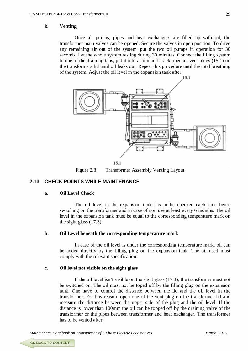
k. Venting
Once all pumps, pipes and heat exchangers are filled up with oil, the
transformer main valves can be opened. Secure the valves in open position. To drive
any remaining air out of the system, put the two oil pumps in operation for 30
seconds. Let the whole system resting during 30 minutes. Connect the filling system
to one of the draining taps, put it into action and crack open all vent plugs (15.1) on
the transformers lid until oil leaks out. Repeat this procedure until the total breathing
of the system. Adjust the oil level in the expansion tank after.
Figure 2.8 Transformer Assembly Venting Layout
2.13 CHECK POIINTS WHILE MAINTENANCE
a. Oil Level Check
The oil level in the expansion tank has to be checked each time beore
switching on the transformer and in case of non use at least every 6 months. The oil
level in the expansion tank must be equal to the corresponding temperature mark on
the sight glass (17.3)
b. Oil Level beneath the corresponding temperature mark
In case of the oil level is under the corresponding temperature mark, oil can
be added directly by the filling plug on the expansion tank. The oil used must
comply with the relevant specification.
c. Oil level not visible on the sight glass
If the oil level isn’t visible on the sight glass (17.3), the transformer must not
be switched on. The oil must not be toped off by the filling plug on the expansion
tank. One have to control the distance between the lid and the oil level in the
transformer. For this reason open one of the vent plug on the transformer lid and
measure the distance between the upper side of the plug and the oil level. If the
distance is lower than 100mm the oil can be topped off by the draining valve of the
transformer or the pipes between transformer and heat exchanger. The transformer
has to be vented after.

CAMTECH/E/14-15/3 Loco Transformer/1.0
March, 2015 Maintenance Handbook on Transformer of 3 Phase Electric Locomotives
30
If the distance between upper side of the plug and the oil level is more than
100mm then the level can only be topped off under vacuum conditions. For this
reason the transformer must be removed from the locomotive and put in a vacuum
oven.
d. Oil level above the corresponding temperature mark.
If the oil level is above the
corresponding temperature mark, oil can
be drained by the draining valve on the
transformer.
Figure 2.9 Expansion Tank
e. Silica Gel Breather
According to the atmospheric conditions, the colour of the silica gel should
be checked roughly every six months. When more than half of it is pink (saturated
with water), then it should be replaced. The saturated silica gel can then be dried out.
Put it in an oven and increase the temperature slowly min 115°C to max. 150°C.
Keep the temperature until the silica gel turns blue again. Silica gel should not be
dried-up in sun light as because of insufficient heat only the outer layer gets dried up.
However, this process should not be repeated too many times; after a while
the silica gel appears to be not so effective, probably due to the ingress of dirt.
Figure 2.10 Silica Gel
f. Leakage of expansion tank
Whenever breather, silica gel colour more than half got pink (saturated with
water)
Bad Condition
Good Condition

CAMTECH/E/14-15/3 Loco Transformer/1.0
Maintenance Handbook on Transformer of 3 Phase Electric Locomotives March, 2015
31
2.14 TRANSFORMER OIL
The transformer unit is filled with 2000 kg of mineral oil. The oil serves as a
cooling and insulating agent.
2.14.1 Oil Specification
Ref. no Characteristic Unit Value Test method
00001 Ident. Text -- Insulation oil T1
00002 Ident no. -- NBT 402614P0201
01000 Description -- The insulation oil T1 is a pure
mineral product without any
additive; it is used in transformer
and switch gear.
01120 Density at 20°C g/ml 0.895 ISO 3675
DIN 51757
01500 Delivery instructions -- ZN 02125
01800 Documentation -- ZLC – documentation and QZ
HSTC 419458
05100 Colour -- Pale yellow to yellow
07900 Special properties -- The oil is not cloudy and is free of
solid particles and water
26350 Pour point
IEC class IA
IEC class IIA
°C - 30
- 45
ISO 3016
ASTM D 97-66
DIN 51597
29300 Flash point in a
enclosed crucible
°C 130 ISO2719
ASTM D 93 – 66
DIN 51758
22500 Thermal expansion
coefficient
K-1
Standard NB
214200
31300 Dielectric loss factor
tan at 90°C 50 Hz
-- 0.005 IEC publ. 247-1978
VDE 0370/ 12.78
35300 Break-down voltage kV 50 IEC publ. 156
43700 Interface tension mN/m 40 ASTM D 971-50
45100 Cinematic viscosity
At + 20°C
At + 40°C
At – 15°C class IEC
IA
At – 30°C class IIA
mm2/s 25
11
800
1800
ISO 3104
51370 Corrosive sulphur
content
-- None DIN 51353
55100 Neutralisation value mgKOH/g 0.03 IEC Publ. 296-1978
55350 Aniline point °C 80 ISO 2977
DIN 51775

CAMTECH/E/14-15/3 Loco Transformer/1.0
March, 2015 Maintenance Handbook on Transformer of 3 Phase Electric Locomotives
32
2.14.2 Purification of Transformer Oil
Figure 2.11 Purification of Transformer Oil
The object of oil purification is to remove all contaminants such as water, carbon
deposits, dirt, sludge, dissolved moisture and gases. The most important quality to be
preserved is the di-electric strength, which is affected by the presence of moisture.
The insulating materials used in the winding are hygroscopic by nature and therefore
moisture is absorbed through defective breathers, gaskets and addition of untreated make up
oil. It is essential to remove these impurities by purifying the oil when the dielectric strength
goes below the permissible limits.
The purification plant should be capable of removing dissolved air/ moisture in the
form of free and finely dispersed water vapour and moisture in solution, sludge and fibers,
gases, carbonaceous products formed due to arcing and drum scale or any other solid
particles from insulating oil.
The plant should be capable of purifying the rated capacity of transformer oil to the
following parameters in maximum three phases.
a. Suspended impurities – maximum 1 micron particle size.
b. Water content – from 100 ppm to less than 5 ppm
c. Gas removal – from fully saturated i.e. 10 to 12% by volume with air/gas
down to less than 0.25%
d. Acidity correction – with addition of clay filters the neutralization index should go
down from 0.5 to 0.05 mg KOH/ gm
of oil.
e. Dielectric strength – Minimum 60 kV
f. Dissipation factor of
oil/ tan delta at 90°C – 0.002
The switching ON & OFF of the heater groups should be thermostatically controlled
so that the temperature of the oil during treatment is not be permitted to rise above 60°C.
Operating vacuum should be better than 1 torr.
CAMTECH/E/14-15/3 Loco Transformer/1.0
Maintenance Handbook on Transformer of 3 Phase Electric Locomotives March, 2015
33
Filtration of EHV grade oil to be carried out at a vacuum level of 98% at a
temperature of 60 degree C and of inhibited oil at a pressure of 0.15 torcillie at a
temperature of 60 degree C, provided the specific resistance is within limits. Filtration
should continue till such time the oil is completely dried. Check the filtered oil sample for
electrical strength and water content and if these parameters are within the limits, the oil is
fit for use and if not, repeat filtration till electric strength and water content are within limits.
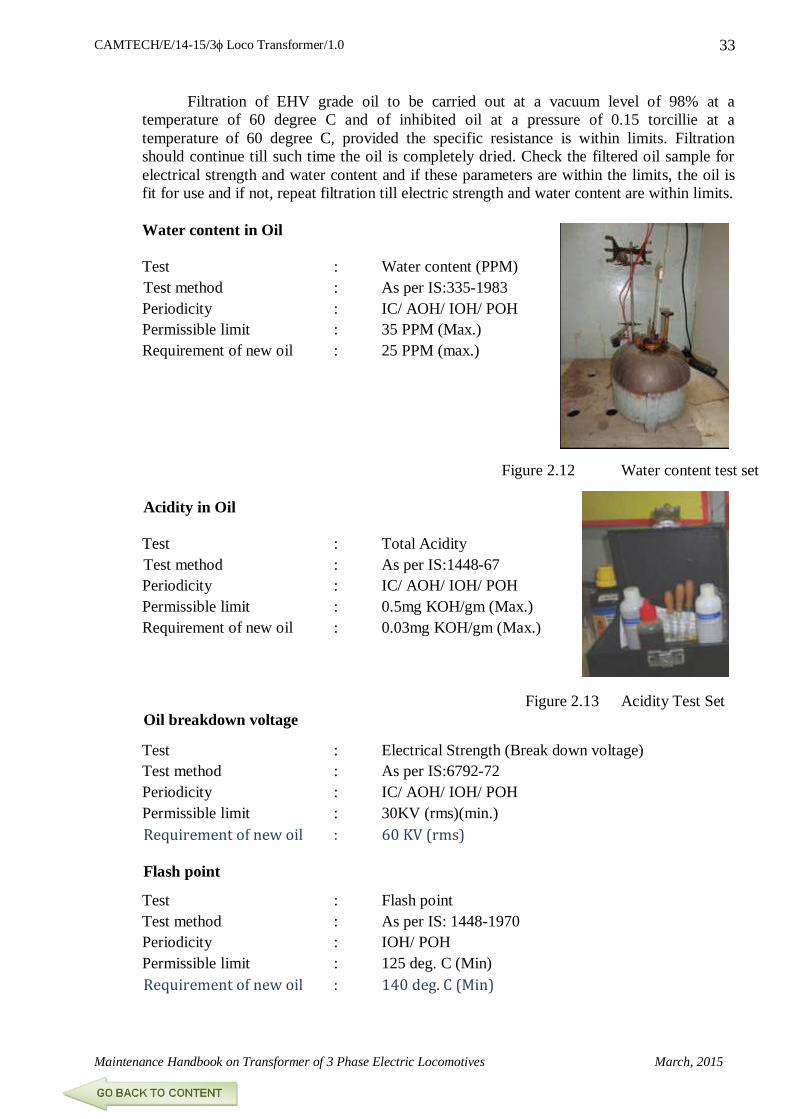
Water content in Oil
Test : Water content (PPM)
Test method : As per IS:335-1983
Periodicity : IC/ AOH/ IOH/ POH
Permissible limit : 35 PPM (Max.)
Requirement of new oil : 25 PPM (max.)
Figure 2.12 Water content test set
Acidity in Oil
Test : Total Acidity
Test method : As per IS:1448-67
Periodicity : IC/ AOH/ IOH/ POH
Permissible limit : 0.5mg KOH/gm (Max.)
Requirement of new oil : 0.03mg KOH/gm (Max.)
Figure 2.13 Acidity Test Set
Oil breakdown voltage
Test : Electrical Strength (Break down voltage)
Test method : As per IS:6792-72
Periodicity : IC/ AOH/ IOH/ POH
Permissible limit : 30KV (rms)(min.)
Requirement of new oil : 60 KV (rms)
Flash point
Test : Flash point
Test method : As per IS: 1448-1970
Periodicity : IOH/ POH
Permissible limit : 125 deg. C (Min)
Requirement of new oil : 140 deg. C (Min)

CAMTECH/E/14-15/3 Loco Transformer/1.0
March, 2015 Maintenance Handbook on Transformer of 3 Phase Electric Locomotives
34
INSULATION RESISTANCE DURING DRYING OUT
Readings of temperature and insulation resistance should be recorded every two
hours, from commencement until the full operation is completed. If these readings are
plotted on a graph, the appearance will be as shown in fig.
It is observed that there are four distinct stages:
A. Initially the insulation resistance drops down to a low value because of rise in
temperature of the oil up to about 60 degree C.
B. Insulation resistance will continue to remain at a low level despite temperature being
maintained at a high level until most of the moisture from the windings and oil has
been driven out.
C. The insulation resistance will thereafter rise gradually and level off, indicating that all
moisture has been driven out and the drying out operation has been completed. At
this point oil circulation should be discontinued.
D. As the oil cools off, the insulation resistance will rise much above the leveling off
point at the end stage (C). This is because the insulation resistance value doubles for a
fall in temperature of about 10°C to 15°C.
2.14.3 Condition Monitoring Of Transformer by Dissolved Gas Analysis
Test : Dissolve gas analysis
Test method : As per SMI 138
Periodicity : IC/ AOH/ IOH/ POH
Permissible limit : As per SMI 138
Requirement of new oil : --
Figure 2.15 DGA Analysis Set (A)
Figure 2.14 Insulation Resistance Graph
INS
UL
AT
ION
RE
SIS
TA
NC
E I
N M
EG
OH
MS
TE
MP
ER
AT
UR
E

CAMTECH/E/14-15/3 Loco Transformer/1.0
Maintenance Handbook on Transformer of 3 Phase Electric Locomotives March, 2015
35
A. Introduction
In order to detect incipient faults in the transformer and to arrest
deterioration/ damage to the transformer insulation, gases dissolved in the
transformer oil are detected, analysed and preventive measures adopted.
Gas Chromatography method is used for detection of the dissolved gases and
identification of incipient faults. The most significant gases generated by
decomposition of oil and deterioration of paper insulation on the conductor are
hydrogen, methane, ethane, ethylene and acetylene. The quantities of these gases
dissolved in transformer oil vary depending upon the type and severity of the fault
conditions.
B. Sensitivity Limits
Gas Chromatography apparatus should be able to detect the following
minimum concentration of dissolved gases:
Hydrogen : 5 ppm
Hydrocarbon : 1 ppm
Carbon oxides : 25 ppm

CAMTECH/E/14-15/3 Loco Transformer/1.0
March, 2015 Maintenance Handbook on Transformer of 3 Phase Electric Locomotives
36
Figure 2.16 DGA Gas Extraction System

CAMTECH/E/14-15/3 Loco Transformer/1.0
Maintenance Handbook on Transformer of 3 Phase Electric Locomotives March, 2015
37
C. Establishment of Reference Values/ Bench Marks
To establish a reference value/ bench mark, gas as generated from initial
sample of oil from each healthy transformer should be collected. Results of the
analysis are taken as a reference value/ benchmark. Results of later periodic analysis
are compared with the benchmark for each transformer.
D. Establishment of Norms
The contents of various dissolved gases in the transformer oil vary with
design and operating conditions. It is desirable that the values of concentration of
gases of healthy transformers of different age groups are to be gathered by the
Railways concerned to evolve suitable norms. However, as a starting point, the
permissible concentrations of dissolved gases in the oil of a healthy transformer are
given below as guidelines:
Gas Less than 4 years
in service (ppm)
4-10 years in
service (ppm)
More than 10 years
in service (ppm)
Hydrogen (H2) 100/150 200/300 200/300
Methane (CH4) 50/70 100/150 200/300
Acetylene (C2 H2) 20/30 30/50 100/150
Ethylene (C2 H4) 100/150 150/200 200/400
Ethane (C2 H6) 30/50 100/150 800/1000
Carbon dioxide (CO2) 3000/3500 4000/5000 9000/12000
E. Diagnosis of Fault
Basic Diagnosis of DGA is based upon the quantities of gases generated.
Types of gases in excess of norms produced by oil decomposition/ cellulosic
material depend upon the hot spot temperature produced by faults.
Characteristics of gases associated with various faults are as under:
Methane (CH4) Low temperature hot spot
Ethane (C2 H6) High temperature hot spot
Ethylene (C2 H4) Strong over heating
Acetylene (C2 H2) Arcing
Hydrogen (H2) Partial discharge
Carbon dioxide (CO2) Thermal decomposition of paper insulation
Carbon monoxide (CO)
F. Word of Caution
To start with the diagnosis, it is necessary to be satisfied that measured gas
concentrations are significant and high enough to warrant diagnosis, because some
amount of gases will always be there due to normal operating conditions without any
fault but it can be sufficient to be misleading. The reasons for the situation are:
Gases formed during the refining processes and not completely removed by oil
degassing.
Gases formed during drying and impregnating the transformer in sheds/
workshops.

CAMTECH/E/14-15/3 Loco Transformer/1.0
March, 2015 Maintenance Handbook on Transformer of 3 Phase Electric Locomotives
38
Gases formed in the event of previous faults and not completely removed from
the oil-impregnated insulation before being refilled with degassed oil.
Gases formed during repairs by brazing, welding, etc.
G. Procedure for Fault Diagnosis
Obtain the results of concentration of various gases in terms of microlitre (ppm).
Compare the concentrations with sensitivity limits. These should be at least ten
times the sensitivity.
If it exceeds sensitivity limits, compare with benchmarks.
If it exceeds benchmarks, compare concentrations with norms depending upon
age and design of transformer.
If one or more gases are above norms, compare with the last sample results; if
increase is sufficient, obtain a check sample.
If the check sample confirms the results, calculate the rate of increase of gas. If
rate of increase is more than 10% per month, it is considered rapid and warrants
immediate further investigations including lifting of core and internal inspection.
If the gas production rate is medium, i.e., less than 10% per month, sampling
frequency to be increased from quarterly to monthly.
Take a planned shut down for further investigation.
*****

CAMTECH/E/14-15/3 Loco Transformer/1.0
Maintenance Handbook on Transformer of 3 Phase Electric Locomotives March, 2015
39
Figure 2.17 Typical Arrangement in a Gas Chromotograph

CAMTECH/E/14-15/3 Loco Transformer/1.0
March, 2015 Maintenance Handbook on Transformer of 3 Phase Electric Locomotives
40
Dissolve Gas Analysis (DGA)
Do’s
1. Give sufficient time for stabilization.
2. Replaced the saptan after every 15 injection
3. Check sapton before start the equipment.
4. Keep standby colomn.
5. Use stabilization electricity with proper earthing.
6. Flush the syringe after each injection.
7. While fire use proper fire extinguisher.
8. Check all leakage before testing.
Don’ts
1. Don’t start TCD before opening of gas.
2. Don’t increase filament current out of safe limit.
3. Don’t excess gas flow in column.
Figure 2.18 Sample Strip Chart
Recording

CAMTECH/E/14-15/3 Loco Transformer/1.0
Maintenance Handbook on Transformer of 3 Phase Electric Locomotives March, 2015
41
CHAPTER 3
MODEL QUESTIONS
3.1 OBJECTIVE
1. Before starting work on faulty circuit it should be ensured that
a. The faulty circuit has been isolated from power supply and earthed.
b. The worker is capable to do the work.
c. The connections are not approachable.
d. None of the above.
2. One can protect himself from electric shock by wearing hand gloves of good.
a. Conducting material
b. Insulating material
c. Semiconductor material
d. Any of the above.
3. Which of the following are safety precautions?
a. Don’t touch live wire or equipment with bare hands.
d. Before switching on DJ, see no one is working inside loco.
c. Use insulated melting and hand gloves.
d. All of the above.
4. Which material is recommended as fire extinguisher in electrical cases?
a. Carbon tetra chloride
b. Carbon dioxide
c. Sulphur hexafluoride
d. Any of the above.
5. The BDV of transformer oil should be
a. 20kV
b. 30kV
c. 40kV
d. 50kV
6. The colour of moisturized silica gel is
a. Pink
b. Blue
c. Yellow
d. Green

CAMTECH/E/14-15/3 Loco Transformer/1.0
March, 2015 Maintenance Handbook on Transformer of 3 Phase Electric Locomotives
42
7. The material filled in breather of transformer is
a. Silicagel
b. Sulphuric acid
c. SF6
d. Mineral oil
8. The protective device to internal fault in a transformer is
a. Current relay
b. Bucholz
c .Lead
d. Silicon steel
9. Three phase Loco Transformer Tank & Lid made of material.
a. Iron
b. Copper
c. Stainless Steel
d. Aluminium
10. Which of the following is not the function of transformer oil
a. Cooling of winding and core.
b. Providing additional insulation
c. Media for are quenching
d. Provides inducting coupling
11. Transformer oil should be free from
a. Odour
b. Gases
c. Temperature
d. Moisture
12. The short circuit test of a transformer gives
a. Copper loss at full load
b. Copper loss at half load
c. Iron loss at any load.
d. Sum of iron loss and copper loss.
13. The type of oil, which is suitable as transformer oil is
a. Crude oil
b. Organic oil
c. Mineral oil
d. Animal oil
14. Transformer is an example of
a. Current transformer
b. Potential transformer
c. Auto transformer
d. All of the above

CAMTECH/E/14-15/3 Loco Transformer/1.0
Maintenance Handbook on Transformer of 3 Phase Electric Locomotives March, 2015
43
15. The colour of fresh transformer oil is
a. Pale yellow
b. Dark brown
c. Blue
d. Colourless
16. The purpose of conservator tank in a transformer is to
a. Monitor oil level
b. Top up the oil
c. Both a & b above
d. None of the above.
17. The saturated silica gel can be dried out in the oven at the max temperature until
silica gel turn blue again.
a. 60°C
b. 160°C
c. 150°C
d. 115°C
18. The oil sample container should be rinsed sample oil quantity
a. ½ Ltrs.
b. 1 Ltrs.
c. 2 Ltrs.
d. 1½ Ltrs.
19. The oil sample are require to test.
a. 2 Ltrs.
b. 3 Ltrs.
c. 4 Ltrs.
d. 5 Ltrs.
20. Dielectric strength of oil should be performed using 12.5 mm ball electrodes with a
gap of-
a. 04mm
b. 05mm
c. 2.5mm
d. 03mm

CAMTECH/E/14-15/3 Loco Transformer/1.0
March, 2015 Maintenance Handbook on Transformer of 3 Phase Electric Locomotives
44
3.2. FILL IN THE BLANKS
1. Transformer is a ………….device
2. G-9 Loco transformer has…………….windings
3. G-9 Loco transformer has………………..tank
4. G-9 Loco Required variable voltage is achieved by the use of ……….………….
5. An emf induced in a coil due to variation of flux in another coil is called……
6. The coils of a transformer are wound on a …………core of ………….material
7. The conductors used in HV and LV windings of loco transformer are…………
8. In G-9 Loco The primary side is protected from the voltage surges by means of
………….placed on the roof of the locomotive.
9. The auxiliary winding is protected from sudden rises in voltage by means of
………………connected across the winding.
10. Ingress of moisture is prevented by means of …………….
11. The complete cooling arrangement includes……….., ………..and…………..
12. The oil pump and the cooler are connected to the conservator by…………………
13. The breather is attached to ………………and contains……………
14. Pink colour of silica gel indicates……………..
15. The colour of transformer oil become dark brown, it indicates presence of ……
……
16. Operating vacuum of transformer oil purification plant shoul be ………….
17. DGA stands for …………………..
18. Transformer must never be lift without its……………….
19. Oil BDV Test six consecutive reading should not lie more then……
20. The lifting ropes should not make a smaller angle then….with the horizontal.
3.3 SAY ‘TRUE’ OR ‘FALSE’
1. Transformer transforms power from one AC circuit to another AC circuit, at same
frequency.
2. Transformer can raise or lower the voltage.
3. Transformer can raise or lower the frequency.
4. Two circuits in a transformer linked by a common magnetic flux through a path of
low reluctance.
5. In case of step up transformer, the transformation ratio will be more than one.

CAMTECH/E/14-15/3 Loco Transformer/1.0
Maintenance Handbook on Transformer of 3 Phase Electric Locomotives March, 2015
45
6. Constructional features of a loco transformer are more or less same other power
transformer.
7. 25 kV condenser/ cable head bushing is mounted on the top of the tank cover.
8. The cooling arrangement of the loco transformer is force oil forced air type.
9. In G-9 Loco the complete cooling equipment is mounted on the cover of the loco
transformer.
10. In G-9 Loco spring-loaded safety valve is fitted to the top of the conservator.
11. Presence of moisture in transformer oil is highly desirable.
12. The oxygen present in transformer reacts with insulation and forms an organic
acid.
13. The solid impurities present in insulation oil strengthen its dielectric strength as
well as insulation of windings.
14. The slackness of winding is desirable factor to create electrical and magnetic
unbalance of the coils.
15. Meggering is done to check the insulation resistance of the windings.
16. The tightening torque of the bolts of tank and lid must be 70 Nm.
17. To arrest the oil leakage from bushing RDSO has recommended to use ISI make
gaskets.
18. Bushing gaskets to be replaced as per TC- 076.
19. New M.S. hardware may be used in transformer flange joints fitting.
20. Periodic maintenance of transformer is essential to ensure safety, reliability and
trouble free operation of Locomotives.
ANSWERS
3.1- 1 (a), 2 (b), 3 (d), 4 (b), 5 (d), 6 (a), 7 (a), 8 (a), 9 (d), 10 (d), 11 (a),
12 (a), 13 (c), 14 (d), 15 (a), 16 (c), 17 (c), 18 (a), 19 (d), 20 (c).
3.2- 1- Static, 2- 04, 3-Aluminium Alloy, 4-GTO or IGBT, 5-Metual Induction,
6- Leminated, Silicon Steel, 7-Continuous Transposed Cu Conductor,
8- Lightening arrester, 9-RCL Damping, 10-Air dehumidifire,
11- Radiator & Blower, 12-oil Pipe, 13-Conservator, Silicagel, 14-Humid
15- Acid & Impurties, 16-1Torr, 17-Incipien fault, 18-Lid, 19-15%, 20-60°.
3.3- 1-T, 2-T, 3-F, 4-T, 5-T, 6-T, 7-T, 8-T, 9-F, 10-T, 11-F,
12-T, 13-F, 14-T, 15-T, 16-T, 17-F, 18-T, 19-F, 20-T.

CAMTECH/E/14-15/3 Loco Transformer/1.0
March, 2015 Maintenance Handbook on Transformer of 3 Phase Electric Locomotives
46
AN APPROACH TO EQUIPMENT FAILURE INVESTIGATION A. On Failure Aspects
1. Occurrence
2. Date of occurrence
3. Past similar occurrences if any
4. Analysis of failure i.e. why did it happen?
5. Whether the rate of failure is worse than other installations?
B. On Maintenance Aspects
1. Whether schedule maintenance & required testing have been carried out on the
failed equipment as per norms stipulated?
2. Does the frequency of maintenance require change?
3. Was the work properly supervised?
4. Was any RDSO modification required to be done?
5. Is any modification possible to avoid failure?
C. About Staff
1. Is the quality of work done satisfactorily?
2. Is the skilled staff properly trained to carry out the work?
3. Is the SMI available with them?
4. Are proper tools available with the staff?
D. About Material
1. Is the material received from approved source?
2. Whether the material is as per approved specification?
3. Can a better material be used?
E. About Testing
1. Is the testing equipment available?
2. Could testing procedure be improved to weed out the failures?
3. Whether testing equipment are calibrated?
F. General Points
Whether following points were checked / performed properly?
1. Proper contact
2. Clearances
3. Capacity
4. Proper contact pressure
5. Crack detections
6. Cleaning
7. Proper connections/alignment
8. Cross checks/super checks

CAMTECH/E/14-15/3 Loco Transformer/1.0
Maintenance Handbook on Transformer of 3 Phase Electric Locomotives March, 2015
47
ANNEXURE – ‘I’
Reliability Action Plan (RAP)
Condition monitoring of loco transformer by Dissolve Gas Analysis. (RDSO/SMI/138 &
OEM Doc. Dt. 27th Nov. 1995).
Replacement of bushing gaskets during IOH inspection.( ELRS/TC/0076 dt. 17.09.2002).
Maintenance of transformer oil in service.(RDSO/ELRS/SMI/158 dtd. 19.01.95).
Maintenance of assembly of electrical terminal of traction winding bushing 2U1-2V1, 2U2-
2V2, 2U3-2V3 & 2U4-2V4 in indigenously
manufactured transformers type LOT 6500/7500 used in 3-phase drive locomotives type
WAG9/WAP5.( RDSO/ELRS/SMI/0228 dt. 13.08.02)
Ensuring tightness of stuchi coupling, base plate and conservator tank foundation bolt
during overhauling. As per OEM guidelines & present
practices followed by shed.
“Ensure instructtions contained in RDSO’s letter no. EL/3.2.1/3-Ph dated 30.07.09 for
arresting oil leakages cases.”

CAMTECH/E/14-15/3 Loco Transformer/1.0
March, 2015 Maintenance Handbook on Transformer of 3 Phase Electric Locomotives
48
REFERENCE
1. ABB Maintenance manual.
2. Electrical Technology Books.
3. RDSO SMI 138, 158
4. RDSO MS 0228.
5. RDSO TC - 076
6. Details collected from various field units (Shed and workshop).
7. Details collected from M/s High voltage Electrical Ltd. , Mumbai
6. Suggestions received during the seminar held on 30.10.2014 organised by
CAMTECH/ Gwalior.

CAMTECH/E/14-15/3 Loco Transformer/1.0
Maintenance Handbook on Transformer of 3 Phase Electric Locomotives March, 2015
49
To upgrade maintenance technologies and
methodologies and achieve improvement in
productivity, performance of all Railway
assets and manpower which inter-alia would
cover reliability, availability, utilisation and
efficiency.
If you have any suggestions and any specific Comments
please write to us.
Contact person : Director (Elect.)
Postal Address : Indian railways
Centre for Advanced
Maintenance technology,
Maharajpur, Gwalior.
Pin code – 474 005
Phone : 0751 – 2470740
0751 – 2470803
E-mail : [email protected]
Fax : 0751 - 2470841
OUR OBJECTIVE