mm application possibilities technical manual 18.12
TRANSCRIPT

Combustion Management Systems
MM APPLICATION POSSIBILITIES Technical Manual 18.12.2019

AUTOFLAME ENGINEERING LTD Unit 1-2, Concorde Business Centre Airport Industrial Estate Wireless Road, Biggin Hill Kent TN16 3YN United Kingdom
Combustion Management Systems
+44 (0)1959 578 820 Tel: [email protected] Email: www.autoflame.com Website:
Technical Manual
MM Application Possibilities
18 December 2019
This manual and all the information contained herein is copyright of Autoflame Engineering Ltd. It may not be copied in the whole or part without the consent of the Managing Director.
Autoflame Engineering Ltd’s policy is one of continuous improvement in both design and manufacture. We therefore reserve the right to amend specifications and/or data without prior notice.
All details contained in this manual are correct at the time of going to print.

Important Notes A knowledge of combustion related procedures and commissioning is essential before embarking work on any of the MM./EGA systems. This is for safety reasons and effective use of the MM/EGA system. Hands on training is required. For details on schedules and fees relating to group training courses and individual instruction, please contact the Autoflame Engineering Ltd. offices at the address listed on the front. Short Form - General Terms and Conditions A full statement of our business terms and conditions are printed on the reverse of all invoices. A copy of these can be issued upon application, if requested in writing. The System equipment and control concepts referred to in this Manual MUST be installed, commissioned and applied by personnel skilled in the various technical disciplines that are inherent to the Autoflame product range, i.e. combustion, electrical and control. The sale of Autoflame’s systems and equipment referred to in this Manual assume that the dealer, purchaser and installer has the necessary skills at his disposal. i.e. A high degree of combustion engineering experience, and a thorough understanding of the local electrical codes of practice concerning boilers, burners and their ancillary systems and equipment. Autoflame’s warranty from point of sale
• Two years on all electronic systems and components. • One year on all mechanical systems, components and sensors.
The warranty assumes that all equipment supplied will be used for the purpose that it was intended and in strict compliance with our technical recommendations. Autoflame’s warranty and guarantee is limited strictly to product build quality, and design. Excluded absolutely are any claims arising from misapplication, incorrect installation and/or incorrect commissioning.

Contents
1 SENSORS ....................................................................................................................................... 1
1.1 Gas Pressure Sensor .......................................................................................................... 1
1.1.1 Mk8 MM Valve Proving Schematics .................................................................................... 4
1.1.2 Mini Mk8 MM Valve Proving Schematics ............................................................................ 9
1.1.3 Calculating Proving Time and Pressure Change .............................................................. 15
1.2 Oil Pressure Sensor .............................................................................................................. 18
1.3 Air Pressure Sensor .............................................................................................................. 20
1.3.1 Air Pressure Proving ......................................................................................................... 23
1.3.2 Air Pressure Tapped Fitting .............................................................................................. 24
1.4 Steam Pressure Sensor ........................................................................................................ 25
1.5 Water Temperature Sensor ................................................................................................... 27
1.6 Outside Temperature Sensor ................................................................................................ 29
1.6.1 Night Setback .................................................................................................................... 34
2 FLAME SAFEGUARD .................................................................................................................. 35
2.1 Burner Control Sequence Diagrams ..................................................................................... 35
2.1.1 Interrupted Pilot – Gas ...................................................................................................... 36
2.1.2 Interrupted Pilot – Oil ........................................................................................................ 37
2.1.3 Intermittent Pilot – Gas with Post VPS .............................................................................. 38
2.2 Flame Scanner Types ........................................................................................................... 39
2.2.1 IR End View Scanner ........................................................................................................ 39
2.2.2 Self-Check End View UV Scanner – High Sensitivity ....................................................... 41
2.2.3 Self-Check Side View UV Scanner – High Sensitivity ...................................................... 43
2.2.4 Mk8 Series Side View UV Scanner ................................................................................... 45
2.2.4 Standard European Side Viewing UV Scanner ................................................................. 46
2.2.6 Standard North American UV Scanner – End Viewing ..................................................... 48
2.2.7 Standard North American UV Scanner – End Viewing High Sensitivity ........................... 50
2.2.8 Swivel Mount Assembly .................................................................................................... 51
2.3 Selection Of UV Scanner Types ........................................................................................... 52
2.3.1 UV Installation ................................................................................................................... 53
2.3.2 UV Self Adaptive Pulse Width Modulation ........................................................................ 54
2.3.3 Dual Flame Scanner Operation ......................................................................................... 55
2.4 Mk8 MM Flame Detection Using An External Flame Switch ................................................ 56
2.5 Mini Mk8 MM Flame Detection Using Ionisation ................................................................... 56
2.6 No Pre-Purge ........................................................................................................................ 57
2.7 Continuous Pilot .................................................................................................................... 58
2.7.1 Continuous Pilot with Interrupted Pilot Sequence ............................................................. 59
2.7.2 Continuous Pilot with Intermittent Pilot Sequence ............................................................ 60
2.8 Mini Mk8 MM Single Servomotor .......................................................................................... 61

2.8.1 Single Servomotor with VSD ............................................................................................. 61
2.8.2 Digital Fan Adapter............................................................................................................ 63
2.8.3 No Air Servomotor ............................................................................................................. 64
2.9 Mk8 MM External 4-20mA Servomotor ................................................................................. 65
2.9.1 Overview ........................................................................................................................... 65
2.9.2 External 4-20mA Servomotor Requirements .................................................................... 65
2.9.3 Wiring ................................................................................................................................ 66
2.9.4 Settings ............................................................................................................................. 67
2.9.5 Commissioning .................................................................................................................. 67
3 HAND, LOW FLAME HOLD AND AUTO ..................................................................................... 68
3.1 Hand Operation ..................................................................................................................... 68
3.2 Low Flame Hold .................................................................................................................... 68
3.3 Auto Operation ...................................................................................................................... 68
4 PID CONTROL.............................................................................................................................. 69
4.1 Proportional Band ................................................................................................................. 69
4.2 Integral Control ...................................................................................................................... 70
4.3 Derivative Control .................................................................................................................. 71
5 INTELLIGENT BOILER SEQUENCING ....................................................................................... 72
5.1 Sequencing Schematics ........................................................................................................ 73
5.1.1 Sequencing Connection Diagram ..................................................................................... 73
5.1.2 DTI Connection Diagram ................................................................................................... 74
5.1.3 Hot Water Example ........................................................................................................... 75
5.1.4 Single/ Multi-Burner Examples .......................................................................................... 76
5.1.5 IBS Communications ......................................................................................................... 77
5.2 Sequencing Options and Parameters ................................................................................... 78
5.3 Hot Water Sequencing .......................................................................................................... 79
5.3.1 Implementing Hot Water Sequencing ............................................................................... 79
5.3.2 Two Port Valve Operation ................................................................................................. 80
5.4 Steam Sequencing ................................................................................................................ 81
5.4.1 Warming Steam Boilers .................................................................................................... 81
5.4.2 Implementing Steam Sequencing ..................................................................................... 81
5.4.3 Low Pressure Steam Sequencing ..................................................................................... 82
5.5 Troubleshooting – Sequencing ............................................................................................. 83
6 MULTI-BURNER OPERATION – MK8 MM ................................................................................. 84
6.1 Multi-Burner Overview ........................................................................................................... 84
6.2 Configuring Multi-Burner Operation ...................................................................................... 85
6.2.1 Wiring ................................................................................................................................ 85
6.2.2 Options and Parameters ................................................................................................... 86
6.2.3 Commissioning in Multi-Burner Operation ........................................................................ 86
6.2.4 Fuel Flow Metering in Multi-Burner Operation .................................................................. 86
6.2.5 Single Point Change in Multi-Burner Operation ................................................................ 86
6.3 Multi-Burner Operation .......................................................................................................... 87
6.3.1 Fully Linked Operation ...................................................................................................... 87
6.3.2 Independent on Fault ........................................................................................................ 88
6.3 Multi-Burner with Water Level Control .................................................................................. 89
6.4 Multi-Burner with EGA ........................................................................................................... 89
6.4.1 Multi-Burner with Single EGA ............................................................................................ 89
6.4.2 Multi-Burner with individual EGAs ..................................................................................... 90
6.5 Multi-Burner External Modulation .......................................................................................... 91
6.5.1 Permanent External Modulation ........................................................................................ 91
6.5.2 Switched External Modulation ........................................................................................... 91

1 Sensors
Page | 1
MM Application Possibilities
1 SENSORS
1.1 Gas Pressure Sensor
IP 65 NEMA 4 Housing & Lid Aluminium Power Consumption 0.1 Watts Mounting Breather hole to be piped or used as differential pressure for IP65/NEMA 4 Installation Sensor should be installed vertically Operating Temp. -25OC to 85OC (-13OF to 185OF)
Part No. Min. Pressure Max. Pressure Zero Range mbar “wg PSI mbar “wg PSI mbar “wg PSI
MM80006 Digital -68 -27 -1 68 27 1 -1.36 to 1.36 -0.54 to 0.54 -0.02 to 0.02 Analogue 12.5 5 0.18 65 25 1 -2.5 to 1.25 -1.0 to 0.5 -0.04 to 0.02
MM80008 Digital -344 -138 -5 344 138 5 -6.88 to 6.88 -2.76 to 2.76 -0.1 to 0.1 Analogue 52 25 0.75 340 135 5 -12.5 to 6.25 -5.0 to 2.5 -0.2 to 0.1
MM80011 Digital -1034 -415 -15 1034 415 15 -20.68 to 20.68 -8.3 to 8.3 -0.3 to 0.3 Analogue 115 50 1.8 750 300 11 -30.0 to 15.0 -12.0 to 6.0 -0.44 to 0.22
MM80012 Digital -2068 -831 -30 2068 831 30 -41.36 to 41.36 -16.62 to 16.62 -0.6 to 0.6 Analogue 207 83 3 1380 550 20 -55.0 to 27.6 -22.0 to 11.0 -0.8 to 0.4
MM80014 Digital -6894 -2770 -100 6894 2770 100 -137.88 to 137.88 -55.4 to 55.4 -2 to 2 Analogue 400 162 6 4000 1620 60 -166.0 to 82.0 -67.0 to 32.0 -2.4 to 1.2
Digital - when used with Mk8 MM, Mini Mk8 MM and Mk8 DTI Analogue - when used with Mk7 MM
Gas Sensor Mk8 MM Mini Mk8 MM Brown T31 T29 Purple T32 T30 Blue T33 T48 Red T34 T49 Connect screen at one end only
Drawing No. 9004
Socket
Plug
Circuit board
Pressure switching unit
Sealing O-rings
1/8” NSP Nylon plug with
breather hole
Quick connection screened flying lead (1.5m) Plug ¼” Tapered male nipple

1 Sensors
Page | 2
MM Application Possibilities
Gas Pressure Sensor

1 Sensors
Page | 3
MM Application Possibilities
Mk8 MM If the Valve Proving System (VPS) facility is to be used then specific options/parameters must be set. Option/Parameter Mk8 MM 125 Fuel pressure sensor mode – fuel 1 126 Fuel pressure sensor mode – fuel 2 127 Fuel pressure sensor mode – fuel 3 128 Fuel pressure sensor mode – fuel 4 129 VPS operation 130 Gas valve configuration 132 Gas valve proving time 133 Maximum pressure change allowed during VPS 134 VPS valve opening time 136 Gas pressure switch – offset lower limit 137 Gas pressure switch – offset upper limit Parameter 41 Gas pressure units Mini Mk8 MM If the Valve Proving System (VPS) facility is to be used then specific options/parameters must be set. Option/Parameter Mini Mk8 MM 125 Fuel pressure sensor mode – fuel 1 126 Fuel pressure sensor mode – fuel 2 128 VPS sensor type 129 VPS operation 130 Gas valve configuration 131 Gas pressure units 132 Gas valve proving time 133 Maximum change allowed during proving time 134 VPS valve opening time 136 Gas pressure switch – offset lower limit 137 Gas pressure switch – offset upper limit 138 Gas static line pressure lower limit offset 156 Terminal T82 function
IT IS THE RESPONSIBILITY OF THE COMMISSIONING ENGINEERS TO ENSURE THAT THE RELEVANT VALVE PROVING SYSTEM STANDARDS ARE ADHERED TO.

1 Sensors
Page | 4
MM Application Possibilities
1.1.1 Mk8 MM Valve Proving Schematics VPS and High/low Pressure Limits using Autoflame Gas Pressure Sensor (3 valves) Option/ parameter 125 (126, 127, or 128 if fuel 2, 3 or 4) to 1 Option/ parameter 130 to 1 or 2 High/low Pressure Limits using Autoflame Gas Pressure Sensor (3 valves) Option/ parameter 125 (126, 127, or 128 if fuel 2, 3 or 4) to 2 Option/ parameter 130 to 1 or 2 Note: Please refer to page 3 for full list of VPS options/parameters.

1 Sensors
Page | 5
MM Application Possibilities
VPS and High/Low Pressure Limits using Autoflame Gas Pressure Sensor (2 valves) Option/ parameter 125 (126, 127, or 128 if fuel 2, 3 or 4) to 1 Option/ parameter 130 to 0 High/Low Pressure Limits using Autoflame Gas Pressure Sensor (2 valves) Option/ parameter 125 (126, 127, or 128 if fuel 2, 3 or 4) to 2 Option/ parameter 130 to 0 Note: Please refer to page 3 for full list of VPS options/parameters.

1 Sensors
Page | 6
MM Application Possibilities
VPS and High/Low Pressure Limits using Autoflame Gas Pressure Sensor (3 valves, single valve pilot) Option/ parameter 125 (126, 127, or 128 if fuel 2, 3 or 4) to 1 Option/ parameter 130 to 4 or 5 High/Low Pressure Limits using Autoflame Gas Pressure Sensor (3 valves, single valve pilot) Option/ parameter 125 (126, 127, or 128 if fuel 2, 3 or 4) to 2 Option/ parameter 130 to 4 or 5 Note: Please refer to page 3 for full list of VPS options/parameters.

1 Sensors
Page | 7
MM Application Possibilities
VPS and High/Low Pressure Limits using Autoflame Gas Pressure Sensor (2 valves, single valve pilot) Option/ parameter 125 (126, 127, or 128 if fuel 2, 3 or 4) to 1 Option/ parameter 130 to 3 High/Low Pressure Limits using Autoflame Gas Pressure Sensor (2 valves, single valve pilot) Option/ parameter 125 (126, 127, or 128 if fuel 2, 3 or 4) to 2 Option/ parameter 130 to 3 Note: Please refer to page 3 for full list of VPS options/parameters.

1 Sensors
Page | 8
MM Application Possibilities
External VPS Option / parameter 125 (126, 127, or 128 if fuel 2, 3 or 4) to 3 Note: Please refer to page 3 for full list of VPS options/parameters.

1 Sensors
Page | 9
MM Application Possibilities
1.1.2 Mini Mk8 MM Valve Proving Schematics VPS and High/Low Pressure limits using Autoflame Gas Pressure Sensor (3 valves) Option/ parameter 125 (126 if fuel 2) to 1 Option/ parameter 128 to 1 Option/ parameter 130 to 1 or 2 High/Low Pressure Limits using Autoflame Gas Pressure Sensor (3 valves) Option/ parameter 125 (126 if fuel 2) to 2 Option/ parameter 128 to 1 Option/ parameter 130 to 1 or 2 Note: Please refer to page 3 for full list of VPS options/parameters.

1 Sensors
Page | 10
MM Application Possibilities
VPS and High/Low Pressure limits using Autoflame Gas Pressure Sensor (2 valves) Option/ parameter 125 (126 if fuel 2) to 1 Option/ parameter 128 to 1 Option/ parameter 130 to 0 High/Low Pressure Limits using Autoflame Gas Pressure Sensor (2 valves) Option/ parameter 125 (126 if fuel 2) to 2 Option/ parameter 128 to 1 Option/ parameter 130 to 0 Note: Please refer to page 3 for full list of VPS options/parameters.

1 Sensors
Page | 11
MM Application Possibilities
VPS and High/Low Pressure limits using Autoflame Gas Pressure Sensor (3 valves, single valve pilot) Option/ parameter 125 (126 if fuel 2) to 1 Option/ parameter 128 to 1 Option/ parameter 130 to 4 or 5 High/Low Pressure Limits using Autoflame Gas Pressure Sensor (3 valves, single valve pilot) Option/ parameter 125 (126 if fuel 2) to 2 Option/ parameter 128 to 1 Option/ parameter 130 to 4 or 5 Note: Please refer to page 3 for full list of VPS options/parameters.
1 Sensors
Page | 12
MM Application Possibilities
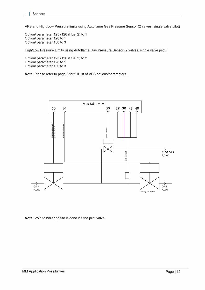
VPS and High/Low Pressure limits using Autoflame Gas Pressure Sensor (2 valves, single valve pilot) Option/ parameter 125 (126 if fuel 2) to 1 Option/ parameter 128 to 1 Option/ parameter 130 to 3 High/Low Pressure Limits using Autoflame Gas Pressure Sensor (2 valves, single valve pilot) Option/ parameter 125 (126 if fuel 2) to 2 Option/ parameter 128 to 1 Option/ parameter 130 to 3 Note: Please refer to page 3 for full list of VPS options/parameters.
Note: Void to boiler phase is done via the pilot valve.

1 Sensors
Page | 13
MM Application Possibilities
VPS using a Low Pressure Switch Option/ parameter 125 (126 if fuel 2) to 1 Option/ parameter 128 to 0 Option/ parameter 156 to 1 Note: Please refer to page 3 for full list of VPS options/parameters.
Note: During VPS, the input on terminal 82 should be on during the VPS air proving and gas proving phases, and at all other VPS phases, the input to terminal 82 should be off. The pressure detected is the static line pressure, so the pressure switch should be set at a value just below this line pressure. When the burner is firing, terminal 82 is not checked.

1 Sensors
Page | 14
MM Application Possibilities
External VPS Option/ parameter 125 (126 if fuel 2) to 3 Note: Please refer to page 3 for full list of VPS options/parameters.

1 Sensors
Page | 15
MM Application Possibilities
1.1.3 Calculating Proving Time and Pressure Change The following formulae may be used for calculating the proving time and pressure change allowed. They are based on DVGW requirements of a leakage rate of 0.1% of the maximum volume flow. Valve Proving Time:
𝑉𝑉𝑉𝑉𝑉𝑉 = 4 × ��𝑙𝑙𝑉𝑉 × 𝑃𝑃𝑃𝑃
𝑀𝑀𝑉𝑉𝑉𝑉 ÷ 1000� + 1�
Vpt Valve proving time in seconds. Ip Inlet pressure in millibars. Pv Pipe volume in litres (volume = πr2 x length, total volume of any interconnecting
pipe between valve seals) Mtp Maximum gas throughput in litres per hour.
Pressure change:
𝑃𝑃𝑃𝑃𝑃𝑃𝑃𝑃𝑃𝑃𝑃𝑃𝑃𝑃𝑃𝑃 𝑐𝑐ℎ𝑎𝑎𝑎𝑎𝑎𝑎𝑃𝑃 = 0.25 × 𝑁𝑁𝑁𝑁𝑁𝑁𝑁𝑁𝑎𝑎𝑎𝑎𝑙𝑙 𝑁𝑁𝑎𝑎𝑙𝑙𝑃𝑃𝑉𝑉 𝑉𝑉𝑃𝑃𝑃𝑃𝑃𝑃𝑃𝑃𝑃𝑃𝑃𝑃𝑃𝑃 (𝑁𝑁𝑚𝑚𝑎𝑎𝑃𝑃) Example Valve proving time:
Inlet pressure = 50mBar Pipe volume = 5litres Max gas flow = 100,000litres per hour
𝑉𝑉𝑉𝑉𝑉𝑉 = 4 × ��50 × 5
100,000 ÷ 1000� + 1�
𝑉𝑉𝑉𝑉𝑉𝑉 = 14𝑃𝑃𝑃𝑃𝑐𝑐𝑃𝑃
Set option 132 = 15 seconds.
Set parameter 132 = 15 seconds. Note: option 132 is set in increments of 5 seconds, values must be rounded up. Pressure change:
Inlet pressure = 50mBar
𝑃𝑃𝑃𝑃𝑃𝑃𝑃𝑃𝑃𝑃𝑃𝑃𝑃𝑃𝑃𝑃 𝑐𝑐ℎ𝑎𝑎𝑎𝑎𝑎𝑎𝑃𝑃 = 0.25 × 50𝑁𝑁𝑚𝑚𝑎𝑎𝑃𝑃
Set Option/Parameter 133 = 12.5 mBar
Note: This is a metric formula, therefore imperial units must be converted before applying this calculation. To convert PSI to mBar multiply the PSI value by 68.94. To convert Cubic Feet to Litres multiply the Cubic Feet value by 28.31. To convert Cubic Feet per hour to Litres multiply your Cubic Feet per hour value by 28.31.

1 Sensors
Page | 16
MM Application Possibilities
Figure 1.1.3.i Mk8 MM Gas Valve Proving Diagram
Figure 1.1.3.i shows the sequence for the Mk8 MM gas valve proving and high/low pressure limits using an Autoflame gas sensor.

1 Sensors
Page | 17
MM Application Possibilities
Figure 1.1.3.ii Mini Mk8 MM Valve Proving Diagram
Figure 1.1.3.ii shows the valve proving operation in the Mini Mk8 MM. The tests have been designed on the Mini Mk8 MM used with block valves; a pressure drop is seen when the valves close after the ‘void to air’ and ‘void to gas’ states. In the VPS air proving phase, after the valves close, there is a 1.5 second delay before the pressure reading is taken. In the VPS gas proving phase, after the valves close, there is a 1.5 second delay before the initial gas pressure reading is taken. The reading taken after this delay must be at least 80% of this measured static pressure.

1 Sensors
Page | 18
MM Application Possibilities
1.2 Oil Pressure Sensor Oil Sensor Mk8 MM Green (2) T35 Blue (3) T48 Red (1) T49 IP 65 NEMA 4 Torque setting Max 25Nm O-Ring material Viton Storage Temperature -25 to 85OC (-13 to 185OF) Operating Temperature -25 to 85 OC (-13 to 185 OF) Media Temperature -25 to 125 OC (-13 to 257 OF) Operating Range 0 to 40 Bar (0 to 600 PSI) Over Pressure Rating 80 Bar (1160 PSI) Burst Pressure Rating 290 Bar (4350 PSI) Maximum 2.5mm flat blade screw driver for electrical connection. Plug fits correctly in one position only, do not force. Do not use case to tighten pressure connection.
19mm (¾”) across flats ¼” NPT
Drawing No. 9002

1 Sensors
Page | 19
MM Application Possibilities
Oil Pressure Sensor
Note: Flying lead supplied length is 1.5m (PMA 1m). Mk8 MM If the oil pressure sensor is being used, the following options/parameters need to be set. Option/Parameter Mk8 MM 125 Fuel pressure sensor mode – fuel 1 126 Fuel pressure sensor mode – fuel 2 127 Fuel pressure sensor mode – fuel 3 128 Fuel pressure sensor mode – fuel 4 139 Oil pressure switch – offset lower limit 140 Oil pressure switch – offset upper limit Parameter 42 Oil pressure units

1 Sensors
Page | 20
MM Application Possibilities
1.3 Air Pressure Sensor
IP 65 NEMA 14 Housing & Lid Aluminium Power Consumption 0.1 Watts Mounting Breather hole to be piped or used as differential pressure for IP65/NEMA 4 Installation Sensor should be installed vertically Operating Temp. -25OC to 85OC (-13OF to 185OF)
Part No. Min. Pressure Max. Pressure Zero Range mbar “wg PSI mbar “wg PSI mbar “wg PSI
MM80005 Digital -68 -27 -1 68 27 1 -1.36 to 1.36 -0.54 to 0.54 -0.02 to 0.02 Analogue -0.75 0.3 0 65 25 1 -2.5 to 1.25 -1.0 to 0.5 -0.02 to 0.02
MM80013 Digital -137 -55 -2 137 55 2 -2.74 to 2.74 -1.1 to 1.1 -0.04 to 0.04 Analogue -1.5 0.6 0 130 50 2 -5.0 to 2.5 -2.0 to 1.0 -0.04 to 0.04
Digital - when used with Mk8 MM, Mini Mk8 MM and Mk8 DTI Analogue - when used with Mk7 MM
Air Sensor Mk8 MM Mini Mk8 MM Brown T31 T29 Purple T32 T30 Blue T33 T48 Red T34 T49 Connect screen at only one end.
Drawing No. 9005
Socket
Plug
Circuit board
Pressure switching unit
Sealing O-rings
1/8” NSP Nylon plug with
breather hole
Quick connection screened flying lead (1.5m) Plug ¼” Tapered male nipple

1 Sensors
Page | 21
MM Application Possibilities
Air Pressure Sensor

1 Sensors
Page | 22
MM Application Possibilities
Mk8 MM If the air pressure sensor is being used, the following options/parameters need to be set. Option/Parameter Mk8 MM 141 Air proving pressure threshold for purge 147 Air pressure error window 148 Air pressure sensor type 149 Air proving pressure threshold Parameter 43 Air pressure sensor units Mini Mk8 MM If the air pressure sensor is being used, the following options/parameters need to be set. Option/Parameter Mini Mk8 MM 141 Air proving pressure threshold for purge 146 Air pressure sensor units 147 Air pressure error 148 Air pressure sensor type 149 Air proving pressure threshold

1 Sensors
Page | 23
MM Application Possibilities
1.3.1 Air Pressure Proving
Pressure sensors are dual channel and self-check. Note:
1. Position 2 must be 0.25”wg (0.62mBar) higher than position 1. 2. Minimum pressure in normal run mode must be higher than position 2. 3. Position 8 must be set equal to position 2 or higher. 4. Default settings for minimum and maximum is 15% above and below entered value.

1 Sensors
Page | 24
MM Application Possibilities
1.3.2 Air Pressure Tapped Fitting The Autoflame Air Pressure Sensor is supplied with a negative pressure port. This can be removed and installed as shown below, to measure a differential pressure. This is only necessary where the air pressure at low fire is below 0.4" w.g. or 1 mbar or when it is a local code requirement.

1 Sensors
Page | 25
MM Application Possibilities
1.4 Steam Pressure Sensor
Steam Pressure Sensor MM Blue (3) T37 White (2) T38 Brown (1) T39
For correct operation the detector must be installed with a pressure siphon loop. Do not install an isolation valve between the detector and the pressure vessel. IP 65 NEMA 4 Torque Setting 15-20Nm O-ring material Viton Max storage temp -25°C to +85 °C (-13OF to 185OF) Max operating temp -25°C to +85 °C (-13OF to 185OF) Media temp (steam) -25°C to +85 °C (-13OF to 185OF) Part No Actual Range Over Pressure Burst Pressure MM10010 (U) 0 – 3.4 bar (0 – 50 PSI) 8 bar (116 PSI) 12 bar (174 PSI) MM10008 (U) 0 – 20 bar (0 – 300 PSI) 50 bar (725 PSI) 75 bar (1087 PSI) MM10009 (U) 0 – 34 bar (0 – 500 PSI) 80 bar (1160 PSI) 100 bar (1450 PSI) MM10017 (U) 0 – 100 bar (0 – 1450 PSI) 200 bar (2900 PSI) 300 bar (4351 PSI) Plug fits correctly in one position only, do not force. Do not use case to tighten pressure connection. Maximum 2.5mm flat blade screwdriver for electrical connections
PG 7 Cable Entry 27mm (1 1/16”) across flats 1/4” NPTT
Drawing No. 9033

1 Sensors
Page | 26
MM Application Possibilities
Steam Pressure Sensor

1 Sensors
Page | 27
MM Application Possibilities
1.5 Water Temperature Sensor Temperature Sensor MM Red T38 Blue T37 Range: 0 – 400°C, 0 - 752°F.
Cable Entry 2 core Screen
½” BSP Thread Connection
Stainless Steel Immersion Pocket
Wire Connections
Drawing No. 9034

1 Sensors
Page | 28
MM Application Possibilities
Temperature Sensor
Part No. mm/inches A B C D
MM10006/100 (U) 211.42/ 8.32 185.75/ 7.31 120/ 4.72 100/ 4 MM10006/150 (U) 261.42/ 10.29 235.75/ 9.28 170/ 6.69 150/ 6 MM10006/200 (U) 311.42/ 12.26 285.75/ 11.25 220/ 8.86 200/ 8 MM10006/250 (U) 361.42/ 14.23 335.75/ 13.22 270/ 10.63 250/ 10 MM10006/400 (U) 511.42/ 20.13 485.75/ 19.12 420/ 16.54 400/ 12

1 Sensors
Page | 29
MM Application Possibilities
1.6 Outside Temperature Sensor
I.P. RATING 65 NEMA 4 Housing Aluminium Power Consumption Powered by MM Mounting Any Orientation
Outside Temperature Compensation Module
OTC Module MM Black T27 Red T28
Sensor Mk8 MM Red 19 Blue 20
2 Core Screen Cable (2m length)
Drawing No. 9022
Fixing Holes
Plastic Water Tight Conduit (1m length)
Conduit Gland
Aluminium Body (101mm length)
Drawing No. 9021

1 Sensors
Page | 30
MM Application Possibilities
Outside Temperature Sensor

1 Sensors
Page | 31
MM Application Possibilities
Outside Temperature Module

1 Sensors
Page | 32
MM Application Possibilities
Outside Temperature Module – Wiring

1 Sensors
Page | 33
MM Application Possibilities
Outside Temperature Compensation Outside Temperature Compensation (OTC) is a function which allows the boiler’s required setpoint to be automatically adjusted according to the outside air temperature. As the ambient air temperature increases the required setpoint will be decreased, and vice versa. To use OTC on a Mk8 MM, an outside temperature sensor is required, part number MM60007. If OTC is being used on MMs in a sequencing/DTI loop, then an outside temperature module is also required, part number MM70015. To use OTC on a Mini Mk8 MM, both an outside temperature module and an outside temperature sensor are required. When using the outside temperature module with a sequencing/DTI loop, the module is wired to this comms loop. Outside temperature compensation should be enabled on all the MMs in the loop, and the module will transfer the outside temperature to all the MMs. The following options must be set: Option Mk8 MM and Mini Mk8 MM 80 Outside temperature compensation 81 Setpoint at minimum outside temperature 82 Minimum outside temperature 83 Setpoint at maximum outside temperature 84 Maximum outside temperature Parameter 88 Outside temperature sensor adjustment If the actual outside temperature exceeds the boundaries set in options 82 and 84, the boiler setpoint will remain at the maximum or minimum setpoints specified by options 81 and 83.
Figure 1.6.i Outside Temperature Compensation Screen – Mk8 MM
1 Sensors
Page | 34
MM Application Possibilities
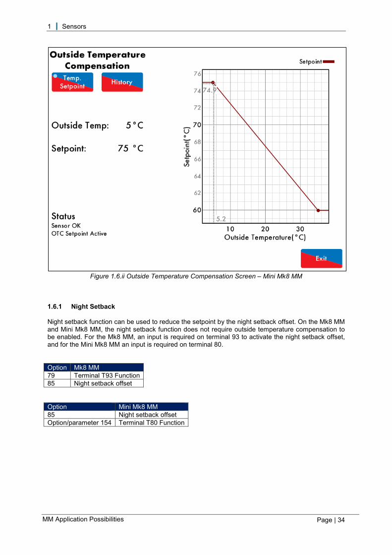
Figure 1.6.ii Outside Temperature Compensation Screen – Mini Mk8 MM
1.6.1 Night Setback Night setback function can be used to reduce the setpoint by the night setback offset. On the Mk8 MM and Mini Mk8 MM, the night setback function does not require outside temperature compensation to be enabled. For the Mk8 MM, an input is required on terminal 93 to activate the night setback offset, and for the Mini Mk8 MM an input is required on terminal 80. Option Mk8 MM 79 Terminal T93 Function 85 Night setback offset Option Mini Mk8 MM 85 Night setback offset Option/parameter 154 Terminal T80 Function

2 Flame Safeguard
Page | 35
MM Application Possibilities
2 FLAME SAFEGUARD
2.1 Burner Control Sequence Diagrams The time to achieve safety shutdown where a fault is detected is within 4 seconds. The resulting safety shutdown state is defined by the shut-off valve terminals being de-energised. The maximum flame failure response time is 1 second. Diagram Notes If VPS is not optioned on the fuel selected, the VPS phases are bypassed. Point idle – this phase is set at power up when no fuel selected on exit from lockout. Point recycle – this phase is set on exit from firing and post purge if VPS has not operated after burner run. Point post purge – this phase is set only if post purge is optioned. Point standby – this phase is set if VPS has operated after burner run. Normal lockout is reset when either the mains lockout reset input is set for 2 seconds or the display screen lockout reset button is pressed for 2 seconds. Prolonged lockout reset is set if either the mains lockout reset input or display screen lockout reset input is set for 10 or more seconds. Normal lockout is set on exit from permanent lockout reset after 20 seconds and is reset in the normal way. Blue waveforms indicate required condition. Values above/below waveform are time in seconds that the state must be continuously incorrect after which a lockout is set. If the waveform is not bold then the status is not important. The following burner control sequence diagrams are shown with example timings: • 3 second window (±1 second) for UV detection for simulated flame • 1 second window for UV loss for flame failure • 3 second window (±1 second) for CPI loss for CPI input wrong state/ no CPI reset • 3 second window (±1 second) for air switch loss for no air proving The Mk8 MM and Mini Mk8 MM has the following default timings: Burner control default timings Seconds Flame failure response time < 1 Time to achieve safety shutdown < 4 Time to achieve lockout < 1

2 Flame Safeguard
Page | 36
MM Application Possibilities
2.1.1 Interrupted Pilot – Gas

2 Flame Safeguard
Page | 37
MM Application Possibilities
2.1.2 Interrupted Pilot – Oil

2 Flame Safeguard
Page | 38
MM Application Possibilities
2.1.3 Intermittent Pilot – Gas with Post VPS

2 Flame Safeguard
Page | 39
MM Application Possibilities
2.2 Flame Scanner Types 2.2.1 IR End View Scanner Part Number: MM 70017 Maximum Operating Temperature: 60°C / 140°F IP 54 Housing Aluminium Power Consumption Powered by external 15V DC supply Mounting Any orientation so that photo tube faces flame Note: Power to the IR scanner is terminated when removed from the magnetic ring socket.
IR Scanner Mk8 MM and Mini Mk8 MM Yellow (29) T29 Green (30) T30 Blue (37) T48 Red (39) T49 Connect screen at one end only.
Serial - +
15v 0v
Perspex window
Gasket
IR sensor
PG11 to ½” – PG11 conduit adaptor
Calcium fluoride lens
O-ring Magnetic ring
½” BSP socket
Drawing No. 9023

2 Flame Safeguard
Page | 40
MM Application Possibilities
IR End View Scanner

2 Flame Safeguard
Page | 41
MM Application Possibilities
2.2.2 Self-Check End View UV Scanner – High Sensitivity Part Number: MM60003/HS Maximum Operating Temperature: 50°C / 122°F IP 54 NEMA 5 Power Consumption Max 0.5W Housing Aluminium Mounting Any orientation
UV Scanner MM Red T51 Blue T50 Yellow T21 Green T22 Connect screen at one end only.
Perspex window
Gasket Paddle UV cell Stepper motor housing PG11 to ½” conduit adaptor Red LED is UV detection Yellow LED is shutter operation Quartz glass O-rings 1” BSP
Drawing No. 9024

2 Flame Safeguard
Page | 42
MM Application Possibilities
Self-Check End View UV Scanner – High Sensitivity

2 Flame Safeguard
Page | 43
MM Application Possibilities
2.2.3 Self-Check Side View UV Scanner – High Sensitivity Part numbers: MM60003/HS/SV Maximum operating temperature: 50°C / 122°F IP 54 Power Consumption Max 0.5W Housing & Lid Aluminium UV Cell High Intensity
UV Scanner MM Red T51 Blue T50 Yellow T21 Green T22 Connect screen at one end only.
Perspex window Gasket UV sensor PG11 to 1/2” conduit adaptor O-ring Viewing tube UV viewing opening Quartz glass Mirror Drawing No. 9025

2 Flame Safeguard
Page | 44
MM Application Possibilities
Self-Check Side View UV Scanner – High Sensitivity

2 Flame Safeguard
Page | 45
MM Application Possibilities
2.2.4 Mk8 Series Side View UV Scanner Part Number: MM80004 Maximum Operating Temperature: 60°C / 140°F
IP 54 NEMA 5 Housing Aluminium Power Consumption Powered by MM Mounting Any orientation so that photo tube faces the flame
UV Scanner MM Red T51 Blue T50 Screen S
Perspex window UV cell PG11 Gland Screened flying lead (1.5m)

2 Flame Safeguard
Page | 46
MM Application Possibilities
2.2.4 Standard European Side Viewing UV Scanner Part number: MM60004 Maximum Operating Temperature: 60°C / 140°F IP 54 NEMA 5 Housing Aluminium Power Consumption Powered by MM Mounting Any orientation so that photo tube faces the flame
UV Scanner MM Red T51 Blue T50 Connect screen at one end only. Perspex window
Gasket UV cell PG11 to ½ conduit adapter Viewing tube UV viewing opening Quartz glass
Note: If wired incorrectly, a limited UV signal will be detected but the LED will not illuminate
Drawing No. 9026
Two red LEDs show UV detection

2 Flame Safeguard
Page | 47
MM Application Possibilities
Standard European Side Viewing UV Scanner

2 Flame Safeguard
Page | 48
MM Application Possibilities
2.2.6 Standard North American UV Scanner – End Viewing Part number: MM60004/U Maximum operating temperature: 60°C / 140°F IP 54 NEMA 5 Housing Aluminium Power Consumption Powered by MM Mounting Any orientation so that photo tube faces flame
UV Scanner MM Red T51 Blue T50 Connect screen at one end only.
Perspex window Gasket UV cell PG11 to1/2” conduit adaptor Quartz glass O-ring ¼”NPT thread socket
Drawing No. 9027
Two red LEDs show UV detection

2 Flame Safeguard
Page | 49
MM Application Possibilities
Standard North American End Viewing UV Scanner

2 Flame Safeguard
Page | 50
MM Application Possibilities
2.2.7 Standard North American UV Scanner – End Viewing High Sensitivity Part number: MM60004/HSU Maximum operating temperature: 60°C / 140°F IP 54 NEMA 5 Housing Aluminium Power Consumption Powered by MM Mounting Any orientation so that photo tube faces flame
UV Scanner MM Red T51 Blue T50 Connect screen at one end only.
Drawing No. 9027
Perspex window Gasket High Sensitivity UV cell PG11 to1/2” conduit adaptor Quartz glass O-ring 1/2” NPT thread socket
Two red LEDs show UV detection

2 Flame Safeguard
Page | 51
MM Application Possibilities
2.2.8 Swivel Mount Assembly
Dimensions: mm (inches) Part A B C D E F Swivel mount 1” UVM60003
100 (3.94) 50 (1.97) 85 (3.35) 104 (4.09) 36 (1.42) 33 (1.30)
Swivel mount 0.5” UVM60004
100 (3.94) 50 (1.97) 85 (3.35) 86 (3.37) 36 (1.42) 26 (0.99)
2 Flame Safeguard
Page | 52
MM Application Possibilities
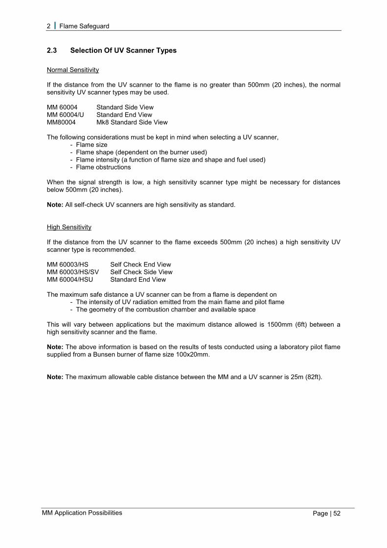
2.3 Selection Of UV Scanner Types Normal Sensitivity If the distance from the UV scanner to the flame is no greater than 500mm (20 inches), the normal sensitivity UV scanner types may be used. MM 60004 Standard Side View MM 60004/U Standard End View MM80004 Mk8 Standard Side View The following considerations must be kept in mind when selecting a UV scanner,
- Flame size - Flame shape (dependent on the burner used) - Flame intensity (a function of flame size and shape and fuel used) - Flame obstructions
When the signal strength is low, a high sensitivity scanner type might be necessary for distances below 500mm (20 inches). Note: All self-check UV scanners are high sensitivity as standard. High Sensitivity If the distance from the UV scanner to the flame exceeds 500mm (20 inches) a high sensitivity UV scanner type is recommended. MM 60003/HS Self Check End View MM 60003/HS/SV Self Check Side View MM 60004/HSU Standard End View The maximum safe distance a UV scanner can be from a flame is dependent on
- The intensity of UV radiation emitted from the main flame and pilot flame - The geometry of the combustion chamber and available space
This will vary between applications but the maximum distance allowed is 1500mm (6ft) between a high sensitivity scanner and the flame. Note: The above information is based on the results of tests conducted using a laboratory pilot flame supplied from a Bunsen burner of flame size 100x20mm. Note: The maximum allowable cable distance between the MM and a UV scanner is 25m (82ft).

2 Flame Safeguard
Page | 53
MM Application Possibilities
2.3.1 UV Installation The distance between the UV scanner and the flame depends on the shape (width) of the flame. Figure 2.3.1.i shows the variation of the maximum allowed distance with the shape of the flame for a standard UV scanner.
Figure 2.3.1.i UV Scanner Installation

2 Flame Safeguard
Page | 54
MM Application Possibilities
2.3.2 UV Self Adaptive Pulse Width Modulation
Figure 2.3.2.i UV Timing Diagram
Figure 2.3.2.i shows a timing diagram for the UV signal. After first safety time, voltage is reduced by 5 volts every 500ms. This is providing the flame signal is above the UV setpoint. If below the UV threshold, voltage will remain at 330 volts. The voltage will not increase during main flame operation. If 5 counts or less have been detected over any 730ms period, the system will invoke a lockout. A short circuit between the two wires connected to the UV would produce 3 counts or less. This is the reason for nominating 5 counts as the lockout level. During normal operation, 300 volts would be applied for a 240ms period after the second safety time. This is providing the UV signal is above the UV setpoint which is set at 25 counts. The setpoint cannot be adjusted. If the UV count is above 25 counts then the time voltage is applied to the UV sensor is decreased by 1ms every 500ms. This time is reduced until a maximum of 10ms has been reached. This helps preserve the life of the UV scanner as the time that voltage is applied to the scanner is reduced dramatically. Every 500ms the recorded counts are averaged and displayed on the MM screen. Note: When using a self-check scanner the timing reduction resets the minute when the paddle operates. Note: As the flame is increasing, the UV counts will stabilise at 5 times the UV threshold set in option/parameter 120. As the flame is dereasing, the UV counts will stabilise at 3 times the UV threshold set in option/parameter 120.

2 Flame Safeguard
Page | 55
MM Application Possibilities
2.3.3 Dual Flame Scanner Operation Dual flame scanner operation is designed to give extra safety to the flame detection system by adding a second scanner to verify that the other scanner is working correctly and is detecting the flame correctly in addition to the self-diagnostics built into the MM. Option/parameter 122 sets dual flame scanner operation. Dual flame scanner operation MM Compatibility IR and UV Mk8 MM, Mini Mk8 MM IR and Ionisation Mini Mk8 MM IR or UV Mk8 MM Ionisation to UV switchover Mini Mk8 MM Both scanners work independently in detecting a flame signal so it is not required that the two scanners have to read the same flame signal strength. It is recommended that a good flame signal is found on both scanners to ensure reliable operation of the dual scanners. IR and UV, IR and Ionisation Both flame scanners must detect a flame when there should be and vice versa. If either flame scanner fails to see a flame when there should be a flame, the MM will lockout on no flame signal, even if the other scanner detects the flame. This is the same for simulated flame; only one scanner must see a flame when there should not be, for the MM to lockout. IR or UV Either flame scanner must detect a flame when there should be and vice versa. If one flame scanner fails to see a flame when there should be but the other scanner does detect a flame, then the MM will continue to fire without a lockout. Only if both flame scanners fail to detect the flame when there should be and vice versa, will the MM lockout. This is the same for simulated flame; either or both scanners must see a flame when there should not be, for the MM to lockout. Ionisation to UV Switchover The ionisation rod can be used to detect the pilot flame and then the UV scanner can be used to check the main flame. The pilot type must be set to interrupted pilot or continuous interrupted pilot (only available on the Mk8 MM) when using ionisation to UV switchover. AGA The AGA (Australian Gas Association) requires that there are 2 types of technologies together checking the flame. Option 122 would need to be set to 3 on the Mk8 MM, and 5 and 6 on the Mk8 MM to comply with this regulation. The UV scanner must be self-check UV scanner to comply with the AGA regulations.

2 Flame Safeguard
Page | 56
MM Application Possibilities
2.4 Mk8 MM Flame Detection Using An External Flame Switch To configure operation with a flame switch, option/parameter 122 must be set to 1. The operation of Terminals 85 and 86 must be as follows: When the flame switch indicates no flame, the voltage on Terminal 85 must be 0Vac, and the voltage on Terminal 86 must be mains voltage (110/230Vac). When the flame switch indicates the presence of a flame, the voltage on Terminal 85 must be mains voltage (110/230Vac), and the voltage on Terminal 86 must be 0Vac. Terminal 85 is the functional input for detecting the flame. Terminal 86 is solely for the purpose of checking that Terminal 85 is operating correctly. Terminal 86 must be seen to be the inverse of Terminal 85, i.e. if Terminal 85 is at 0Vac, terminal 86 must be at mains voltage and if Terminal 85 is at mains voltage, Terminal 86 must be at 0Vac. If Terminal 86 does not follow the inverse of Terminal 85 the following lockout will occur – ‘Terminal 86 inverse.’ Note: High purge interlock (parameter #92) will not operate with flame switch. Within the MM there is a latency of 250 milliseconds on the monitoring of Terminal 85. To ensure a 1 second overall flame failure response time, it is essential that the response time of the flame switch is set to no more than 750 milliseconds. Flame switches often provide a volt free changeover contact to indicate the flame status. Alternatively, they may provide a pair of `inverse’ outputs. If the flame switch only provides a single output terminal, a relay will have to be installed between the flame switch and the MM to provide a set of volt free changeover contacts. 2.5 Mini Mk8 MM Flame Detection Using Ionisation As well as using UV or IR, the Mini Mk8 MM can detect a flame using an ionisation signal/flame rod. This is wired into terminal 64 and the cable must be shielded. For ionisation, the flame will be signalled when the rectification voltage is above 30Vdc, the maximum sensed rectification voltage is 540Vdc, above which a Lockout will be generated.

2 Flame Safeguard
Page | 57
MM Application Possibilities
2.6 No Pre-Purge It is possible to minimise the burner start-up time by bypassing the pre-purge. The major advantage of this control means that the overall boiler efficiency is increased by minimising the heat loss to the stack during a purge cycle. This means the burner starts-up quicker therefore reaching setpoint in a reduced time. According to the EN676 European regulation, the burner is allowed to restart without a pre-purge if the burner has recycled due to operational temperature/pressure. When the burner is stopped by a lockout then this procedure is not allowed and the burner will have to start-up as normal with a pre-purge. In order for no pre-purge to be active, valve proving must take place and finish successfully. If this valve proving operation is successful then the burner may start-up without a pre-purge. In order to initiate the no pre-purge feature, option/ parameter 143 must be set to a value of 1. During the first start-up the burner will start with a pre-purge initiated. Once the complete commissioning curve has been entered and the burner has started successfully, the burner will then start-up every time with no pre-purge. If the burner goes above its setpoint and turns off on high temperature/ pressure, then the next time the burner starts-up, it will go through the VPS operation and then light off without a pre-purge, i.e. the burner has shut down in a controlled manner and the gas valves have been checked for integrity. According to the EN676 regulation, the burner is only allowed to work in this manner if VPS operation has been set to operate before the burner starts up; option/parameter 129 must be set to 0. The start sequence without pre-purge is as follows:
1. Firstly the system goes through its internal tests and relay checks. 2. Call for heat on Terminal 57 activates and the system will go through the VPS operation. 3. If this operation is successful then the MM will drive the channels to the light off or start
position. 4. Once all channels reach the start position then the burner will light off.
burner shuts down in an abrupt manner, e.g. loss of power to the unit, then the next time the burner starts-up a complete purge will be initiated. If no pre-purge is enabled in option/parameter 143, and one or more of the following conditions occur, the next time the burner starts up, a complete pre-purge will be initiated:
• Burner lockout • Loss of power to the MM • VPS checks have failed • MM has been in standby for 24 hours or more
Note: Pre-purge is only available on fuels which are optioned as gaseous.

2 Flame Safeguard
Page | 58
MM Application Possibilities
2.7 Continuous Pilot The Mk8 MM has a continuous pilot (pilot relight) feature. If continuous pilot is enabled, when the burner goes above its off differential of the required setpoint, the burner will continue to fire with only the pilot valves energised. To enable continuous pilot, set option/ parameter 111 to either 3 or 4 interrupted continuous pilot or intermittent continuous pilot. If the burner goes off on high temperature/ pressure, then the pilot will continue to fire for a time period, set in option 71. After the time set in option 71, if the main flame is not re-established through load demand, the system will shut down and recycle. Option 72 sets the offset above the required setpoint where during the time period, if the actual temperature/ pressure goes above this value, the pilot will turn off as well. In the situation when the burner switches back to pilot flame, the burner will open the pilot valves and after the second safety time (option/parameter 116), the burner will close its main valves. During the hot standby position the gas pressure is checked by the gas sensor, it is important that the main valves and pilot valves are connected with a small measuring pipeline. When burner is ready to go back to main flame the main fuel valves will open and after the second safety time the pilot valves will be closed and the normal operation will start again. When default settings are used, the quickest the MM can go from pilot to high fire once the stat comes on is approximately 30 seconds. At the slowest motor travel speed and the maximum timings, it would take approximately 1minute and 30 seconds to from pilot to high fire. It is recommend that assured low fire shutoff (parameter 100) is used with continuous pilot.

2 Flame Safeguard
Page | 59
MM Application Possibilities
2.7.1 Continuous Pilot with Interrupted Pilot Sequence
Start
T53 Circuit Made?
No
Yes
Purge
Ignition On
Main Valves On
Stat Circuit Made?
Ignition Off
Pilot Valves On
Stat Circuit Made?
Firing
Stat Circuit Made?
Move to low fire
Continuous Pilot
T53 Circuit Made?
Post purge
Continuous Pilot timer expired?
Main Valves Off
T53 Circuit Made?
Yes
No
Yes
No
Yes
Pilot Valves Off
No
Yes
No
No
Yes
Yes
No
Return to Start
Continuous Pilot offset breached?
Yes No
Move to Golden start (if commissioned)
Main Valves Off
Pilot Valves Off
Pilot Valves On

2 Flame Safeguard
Page | 60
MM Application Possibilities
2.7.2 Continuous Pilot with Intermittent Pilot Sequence Start
T53 Circuit Made?
No
Yes
Purge
Ignition On
Main Valves On
Stat Circuit Made?
Ignition Off
Pilot Valves On
Stat Circuit Made?
Firing
Stat Circuit Made?
Move to low fire
T53 Circuit Made?
Post purge
Continuous Pilot timer expired?
Main Valves Off
T53 Circuit Made?
Yes
No
Yes
No
Yes
Pilot Valves Off
No
Yes
No
No
Yes
Yes
No
Return to Start
Continuous Pilot offset breached?
Yes No
Main Valves & Pilot Valves Off
Continuous Pilot
Move to Golden start (if commissioned)

2 Flame Safeguard
Page | 61
MM Application Possibilities
2.8 Mini Mk8 MM Single Servomotor 2.8.1 Single Servomotor with VSD For applications where only the VSD controls the air going into the burner and no air servomotor is required, the Mini Mk8 MM can be set for single servomotor with VSD. The MM will make changes to the fuel servomotor and VSD in synchronisation as the firing rate modulates up and down. When using a single servomotor with VSD, the MM checks that the VSD feedback is within the fault tolerance bands set in option 99 as the fuel servomotor drives open to increase the firing rate. If the VSD feedback is not higher than the tolerance band at that the servomotor angle, then the servomotor will wait until the VSD ramps up to meet this limit at minimum. This prevents the burner from being too fuel-rich as the firing rate increases. As the fuel servomotor closes, there is a natural lag in the VSD feedback as it slows down; the fuel servomotor still waits for the VSD but does not modify the target VSD speed.
Relative channelposition
Time
Fuel (servo)
Air(VSD)
Natural lag
Air channel advanced by VSD
tolerance band
High Fire
Low Fire
VSD Band
Figure 2.8.1.i Single Servomotor with VSD Diagram Option 4 Air Channel must be set to setting 1 for ‘VSD Channel 4,’ and options 90 to 99 must be set according to the VSD settings. Option 8 must be set to ‘Channel 1 only.’ Option 89 allows the user to send the high signal to the VSD only when the T58 is required to come on, to prevent the burner being forced with air at start-up. Note: EGA trim will not work with single servomotor with VSD. For single servomotor with VSD, both the fuel servomotor on channel 1 and the VSD on channel 4 are wired as normal to the MM. Please refer to the Mini Mk8 MM Installation and Commissioning Guide.

2 Flame Safeguard
Page | 62
MM Application Possibilities
Figure 2.8.1.i Single Servomotor with VSD
The commissioning procedure remains the same, however only the channel 1 gas servomotor position and channel 4 VSD position needs be entered for each point. In Run mode the system will show the servomotor position and VSD input and output signals.

2 Flame Safeguard
Page | 63
MM Application Possibilities
2.8.2 Digital Fan Adapter For applications where the burner uses a digital fan, a PCB can be fitted to the MM to connect to output to a digital fan. The digital fan adapter is plugged into VSD terminals 1 – 3 and 10 – 12. The power supplied to PCB comes from the IR scanner terminals 48 and 49. Please see wiring diagram below:
The digital fan adapter must be purchased according to the specification of the digital fan. The device must be programmed with the correct speed settings for the fan to be used and must be fitted with the correct interface components. Before purchasing this item please contact Autoflame Engineering. Options 90 to 99 must be set according to the VSD settings. The commissioning procedure remains the same. In Run mode the system will show the servomotor position and VSD input and output signals.

2 Flame Safeguard
Page | 64
MM Application Possibilities
2.8.3 No Air Servomotor Some burner applications use natural draught to supply air for combustion without the need for air blower for forced draught and there is no air damper, so the air supplied to the burner is at atmospheric pressure. In such applications there is no need for control on the air channel and only the fuel channel requires controlling. The Mini Mk8 MM allows the system to be set so that the burner is commissioned with channel 1 servomotor only to control the fuel flow. This configuration can also be used for pre-mix burners where the fuel to air volume ratio is not varied. In these applications, channel 1 is sued to vary the volume of combined air and fuel. The gas servomotor is wired as normal to the MM, and option 4 must be set to ‘No Air Channel.’ Option 8 must be set to ‘Channel 1 only.’
Figure 2.8.3.i Commissioning No Air Servomotor
The commission procedure follows the normal steps but with channel 1 servomotor only. For more information on using the Mini Mk8 MM on an atmospheric burner or pre-mix burner and what limit switches or purge delay is required, please contact Autoflame Engineering Ltd.

2 Flame Safeguard
Page | 65
MM Application Possibilities
2.9 Mk8 MM External 4-20mA Servomotor 2.9.1 Overview A third party 4-20mA servomotor can be used with the Mk8 MM in conjunction with a Universal IO Module. The IO module acts as an interface between the MM and the external 4-20mA servomotors. This feature is used in sites where the fuel and/or air going into the burner cannot be controlled by mains voltage or where pneumatic control already exists. The MM will send a 4-20mA signal out from the IO module for the position of the servomotor for it to move according to the commissioned fuel-air curve and receives a 4-20mA signal back to the IO to indicate where the external 4-20mA servomotor position is currently. The Mk8 MM channels which can be controlled using an external 4-20mA servomotor include channels 1 – 4 and 7. Any or all of the 5 servomotor channels available on the Mk8 MM can be independently configured to use an externa 4-20mA servomotor or the Autoflame servomotor. Servomotor channel on Mk8 MM IO Module Analogue Input/ Output 1 1 2 2 3 3 4 4 7 5 2.9.2 External 4-20mA Servomotor Requirements In order for the MM to control the servomotor channels via external 4-20mA servomotors, the following requirements must be met:
1. The external 4-20mA servomotor must be capable of being controlled to an accuracy no higher than 0.5° angular accuracy.
2. There must be both a 4-20mA input and 4-20mA positional feedback from the external 4-20mA servomotor.
3. The feedback signal from the external 4-20mA servomotor must correlate directly to the input signal. For example, if 8mA is outputted from the MM, then the servomotor should move to the position that gives 8mA feedback to the MM.
4. The range of the external 4-20mA servomotor is 4mA for the closed position at 0.0o up to 20mA for the open position at 90.0o position, with a linear scaling. For example 12mA will correspond to a position of 45.0o.
5. Neither the input or output signal from the external 4-20mA servomotor follows loop control; this means that if the MM sends a signal of 10mA to the servomotor via the IO module, and the servomotor does not have angular position to return a 10mA signal back to the MM, then a fault condition will occur.

2 Flame Safeguard
Page | 66
MM Application Possibilities
2.9.3 Wiring

2 Flame Safeguard
Page | 67
MM Application Possibilities
2.9.4 Settings It is possible to use a combination of external 4-20mA servomotors and Autoflame servomotor, for example, channel 1 can be set as an Autoflame servomotor and channel 2 can be set as an external 4-20mA servomotor. The degree of accuracy when using an external 4-20mA servomotor via a Universal IO module is 0.5o, in comparison to the accuracy level of 0.1o which is possible on the Autoflame servomotor. The control method for each servomotor can be set by the following options: Option Mk8 MM 86 Channel 1 Servo Control Method 87 Channel 2 Servo Control Method 88 Channel 3 Servo Control Method 89 Channel 4 Servo Control Method Expansion Option Mk8 MM 81 Draught Servo Control Method The IO module must be configured for ID 1. Please refer to the Autoflame PC Software Guide for more information. The MM will automatically configure all other settings in the IO module unit required for operation. Please note that mixed IO software version 3.01 or above is required. 2.9.5 Commissioning
Figure 2.9.5.i Commissioning External 4-20mA Servomotor
The commission procedure for the Mk8 MM with external 4-20mA servomotors follows the normal commissioning procedure, with the positions displayed in angular degrees. In run mode, the servomotor screens show the same information as that displayed for Autoflame servomotors.

3 Hand, Low Flame Hold and Auto
Page | 68
MM Application Possibilities
3 HAND, LOW FLAME HOLD AND AUTO
3.1 Hand Operation Hand operation enables the firing rate positions to be set to a specific position, in the range of low to high fire, when the burner is firing. Fuel flow metering must be entered. Sequencing will not operate correctly if the MM is in hand mode. Hand mode can only be activated when the burner is firing. Mk8 MM The Mk8 MM will go into hand mode when a voltage is detected on Terminal 94 or when the hand mode button is pressed in the Status screen. Arrows will then appear on the screen which can be used to increase and decrease the firing rate. Once the hand mode is deactivated, the MM will go to auto mode and fire according to normal modulation. On the Mini Mk8 MM the transfer between hand and auto mode is always bumpless. If Hand and Low Flame Hold are selected at the same time via Terminals 94 and 95, then Low Flame Hold takes priority. Mini Mk8 MM The Mini Mk8 MM will go into hand mode when the hand mode button is pressed in the Status screen. Arrows will then appear on the screen which can be used to increase and decrease the firing rate. Once the hand mode is deactivated, the MM will go to auto mode and fire according to normal modulation. On the Mini Mk8 MM the transfer between hand and auto mode is always bumpless. If the low flame hold input is activated on terminal 81 (see option/parameter 155), then this will take priority over the hand button pressed in the Status screen. 3.2 Low Flame Hold Low flame hold is the state when the MM’s firing rate goes to its low fire position, while the burner is firing. Fuel flow metering must be entered. Sequencing will not operate correctly if the MM is in low flame hold. Mk8 MM To put the Mk8 MM into low flame hold, put an input on terminal 95 go to the Status screen and press the low flame hold button. The low fire position will be maintained until the input on terminal 95 is removed or the button is pressed again. When switching from low flame hold to auto the MM will return to normal modulation. Mini Mk8 MM To put the Mini Mk8 MM into low flame hold, go to the Status screen and press the low flame hold button, or put an input on terminal 81 (option/parameter 155 must be set to 2). Once out of low flame hold, the MM will return to normal modulation. 3.3 Auto Operation The MM ‘Auto’ operation enables the burner modulation to maintain the setpoint; the firing rate will modulate according to how far away the actual temperature or pressure is away from the required setpoint. The firing rate is determined from the fuel flow metering entered via option 57; the more accurate the fuel flow metering, the more accurate the firing rate.

4 PID Control
Page | 69
MM Application Possibilities
4 PID CONTROL
The standard control algorithm used by Autoflame to control the fuel/air ratio is PID control; Proportional-Integral-Derivative control. The control algorithm compares the actual measured temperature or pressure and compares it to the user specified setpoint temperature or pressure. Depending on the measured and setpoint values, the MM’s PID control will then either modulate the burner up or down. The rate of change or speed of the burner modulation in relation to changes in measured temperature or pressure is dependent on the settings of the PID control. The PID control action is the sum of the “Proportional” + “Integral” + “Derivative” actions of the PID control. Each contributes to how the 3 term PID control modulates the burner and each operates as outlined below. Most applications can be controlled adequately using just the Proportional and Integral settings; a PI control setup. Modification to the Autoflame system settings should only ever be carried out by qualified combustion engineers. Changes to the Autoflame control system setup has the potential to make the controller operate in an unstable and potentially unsafe manner. 4.1 Proportional Band The Proportional term is specified in option 6 by defining the “Proportional band” (P-Band). The P-Band is simply an offset from the setpoint pressure or temperature. Outside and below the P-Band, the MM’s PID control will modulate the burner at maximum flame, upon reaching the P-Band, it will then modulate the burner linearly down (see option 6).
Figure 4.1.i Proportional Band

4 PID Control
Page | 70
MM Application Possibilities
4.2 Integral Control The Integral term is specified in option 7, where the “Integral time”, also known as “Reset time”, is set. Within a threshold of the P-Band, the integral term has the effect of increasing or decreasing the burner firing rate by a specific amount every “n” seconds. The amount the firing rate is adjusted by is specified in parameter 106, the default is 10% of the difference between the measured and setpoint temperature or pressure values, and the time period this amount is added, every “n” seconds, “n” is specified in option 7, the default is 60s. Note: The Mini Mk8 MM does not use parameter 106. Option 7 is integral time, for which every ‘n’ seconds, 10% of the present offset from the setpoint is added when below the setpoint, or removed when above the setpoint, to the present proportional value.
Figure 4.2.i Integral Control
(Parameter 48 = 0.8, Integral operation band of P-Band)

4 PID Control
Page | 71
MM Application Possibilities
4.3 Derivative Control The Derivative term of the control system analyses the rate of change in the difference between the measured and set point temperature or pressure. Derivative specific options are set in option 37, 38 and 39. The time interval over which the compared and measured temperature or pressure values are taken is set in option 37, the derivative dead-band or margin above and below the required set point in which no derivative action occurs is set in option 38, and the response sensitivity as a percentage of firing rate increase or decrease is defined in option 39. Note: The Mini Mk8 MM does not use option 39. The derivative response sensitivity is set as default to 10% firing rate. The derivative time set via option 37 is the time taken to add/remove additional 10% to the firing rate based on the actual value and the required value.
Figure 4.3.i Derivative Control
NOTE: The derivative action occurs at all points outside of the deadband. This includes within the proportional band.

5 Intelligent Boiler Sequencing
Page | 72
MM Application Possibilities
5 INTELLIGENT BOILER SEQUENCING
The objective of Intelligent Boiler Sequencing (IBS) is to ensure that the minimum number of boiler/ burner units are in operation at any one time to satisfy the heat or steam requirement imposed upon the boiler plant, in the case of multi-boiler installations. The benefits from using IBS include an increased savings in electrical costs, a reduction in thermal stress on the lag boilers, and an increase in overall plant efficiency. It is possible on the MMs to select steam sequencing, low pressure steam sequencing and hot water sequencing. There are variations of the IBS software that can be selected via the options/parameters procedure: hot water boilers, and steam boilers. A maximum of ten MM, EGA, universal I/O modules may be interconnected by a two wire screened data cable. Any MM interconnected may be selected as the lead boiler for the sequencing. The lead boiler is identified by:
1. Connecting a mains voltage onto Terminal 88 (only on the Mk8 MM) 2. Selecting Lead boiler in the IBS screen 3. Instructing the modules via the DTI module (Data Transfer Interface) or by PC CEMS Audit
software. The sequence order of the MMs in the loop can be changed by changing their ID numbers or by changing the order on the DTI if shuffle sequencing is enabled through parameter 101. Sequencing can be used with external load detector and multi-burner operation, but it cannot be used with external modulation.

5 Intelligent Boiler Sequencing
Page | 73
MM Application Possibilities
5.1 Sequencing Schematics 5.1.1 Sequencing Connection Diagram

5 Intelligent Boiler Sequencing
Page | 74
MM Application Possibilities
5.1.2 DTI Connection Diagram

5 Intelligent Boiler Sequencing
Page | 75
MM Application Possibilities
5.1.3 Hot Water Example

5 Intelligent Boiler Sequencing
Page | 76
MM Application Possibilities
5.1.4 Single/ Multi-Burner Examples
Boiler 1 Boiler 2 Boiler 3
1 2 3
1 2 3 4 5 6
1 2 3 4 Note: Multi-burner operation is not available on the Mini Mk8 MM

5 Intelligent Boiler Sequencing
Page | 77
MM Application Possibilities
5.1.5 IBS Communications

5 Intelligent Boiler Sequencing
Page | 78
MM Application Possibilities
5.2 Sequencing Options and Parameters Options and Parameters must only be changed by factory trained technicians who have a thorough appreciation of the Autoflame combustion systems and the combustion process in general. Any person changing Options and Parameters who does not have the correct factory training and understanding of these settings may place themselves and others in a potentially dangerous situation. The following tables show the sequencing options, parameters and expansion options (Mk8 MM only) for the Mk8 MM and Mini Mk8 MM. Option Description 16 Sequencing and DTI enable 33 MM identification 35 Sequence scan time 40 Warming facility for low pressure steam 41 Warming mode 42 Standby setpoint 53 Steam sequencing burner off time 54 Steam sequencing burner on time 57 Fuel flow metering 100 (Mini Mk8 MM only) Sequencing/DTI or Modbus operation Parameter Description 1 Sequence scan time set when unit goes offline 3 Number of boilers initially on 5 Modulation timeout 57 Highest MM ID 62 Hot water sequencing 86 IBS change down threshold 87 IBS change up threshold 101 Shuffle sequencing Expansion Option (Mk8 MM only) Description 100 Sequencing/DTI or Modbus function

5 Intelligent Boiler Sequencing
Page | 79
MM Application Possibilities
5.3 Hot Water Sequencing 5.3.1 Implementing Hot Water Sequencing For hot water sequencing, a temperature detector must be fitted to all the MMs (only Master MMs in Multi-Burner operation if option 14 is set to 1 – Mk8 MM only) and option 1 must be set to 0 or 5. As sequencing is based on firing rate, the MMs must have fuel flow metering entered, see option 57. The burner rating is set as point 1 high fire in fuel flow commissioning. See the Mk8 MM Installation and Commissioning Guide and Mini Mk8 MM Installation and Commissioning Guide for more information on fuel flow commissioning. The MMs can be configured for sequencing either in Commissioning Mode, or Online Changes; this allows the commissioning engineer to implement/adjust sequencing later after the burners have been commissioned. Each MM in the sequencing loop must be set with an individual ID number through option 33; no two MMs can have the same ID number in sequencing, Multi-Burner operation, and when connected to a DTI/Modbus interface. The highest MM ID number should be set for that sequencing loop in parameter 57, so the system only looks for communications with these MMs. The maximum number of MMs that can be in a sequence loop is 10. If there is a DTI in the sequence loop, to control the sequence loop via the DTI, parameter 101 must be set to 1. To enable sequencing, option 16 must be set to 1, or 3 for sequencing with DTI. If option 16 is set to 3, then the DTI/Modbus interface is capable of some remote control. The individual and global required setpoint, lead boiler select, sequence order, enable/disable and firing rate can be set remotely. If an MM’s firing rate is set by the DTI/Modbus interface, then that MM will not follow the sequencing loop. For hot water sequencing, option 53 must be set to 0 to disable the standby warming which is used in steam sequencing. Options 40 and 41 must be set to 0 on all the MMs in the sequencing loop. If warming is required for lag hot water boilers, then hot water sequencing can function like steam sequencing by setting option 62. In a sequence loop, there is one lead burner, and the rests are lag MMs. The lead burner identifies its own firing rate by looking at its fuel flow metering data, proportional to the system’s load requirements. Having established the percentage firing rate and maximum heating capacity, the MM will calculate the amount of heat being contributed to the system by this burner. The sequence scan time, see option 35, sets after how long the firing rates of all the MMs in the loop are assessed. The scan time has a critical effect on the responsiveness of the sequencing system. Too long a scan can result in the boilers not coming online quick enough to meet the load demand; too short a scan time (shorter than the burner start-up time) can cause another boiler to be brought online before the previous lag boiler has started firing. The scan time should normally be set at minimum, the start-up time for the burner. The lead burner looks at its firing rate and sends a command to the lag MMs to either contribute to load because it cannot reach the setpoint, or to stop contributing to the load because the system has met the load demand. Only one lead burner can be selected at one time, if more than 1 is selected as lead burner, then the MMs will ignore the sequencing loop commands and return to independent firing. Parameter 2 sets how often the ‘bus driver’ MM requests and transmit information to the other MM The ‘bus driver’ is always the MM with the lowest ID number. The MMs will start, continue or stop contributing to the load based on the change up and down thresholds, see parameter 86 and 87. The next lag MM will be brought online if the lead burner cannot cope with the load demand, and its firing rate is above the change up threshold. Alternatively, the MM will go into standby, warming or offline if the last two lag MMs have a total combined firing rate less than the change down threshold, because the system can cope with the load demand.

5 Intelligent Boiler Sequencing
Page | 80
MM Application Possibilities
For example, if the change up threshold in parameter 87 is set at 90%, then if the last firing MM in the sequence is above 90% firing rate, then upon the elapse of the next scan time, the next lag MM will be brought online. If at the next scan time, the firing rates of the last two online lag MM are 30% and 40% respectively, and the change down threshold in parameter 86 is set at 80%, then the last lag MM will go into standby, warming or off depending on how the sequencing mode is set. If a lag burner fails to start when requested, the scan time will be decreased by the offset set in parameter 1, until it is automatically ignored from the sequencing communication loop. If a lag burner fails to modulate after being requested to contribute to the load requirement, then that MM will be ignored from the sequencing communication loop after a time delay set in parameter 5. After a power recycle, the number of MMs which are initially set on when the MMs start up again, is set in parameter 3. 5.3.2 Two Port Valve Operation In hot water sequencing, when there is no demand for all of the lag boilers to be on, the system will close the two port valves on the lag boilers that do not need to be on. This will stop the hot water circulating in the system from passing through the boiler and the heat being wasted. It is possible to use Terminal 78 which is a switched neutral to control the two port valve. This works by switching to neutral once the burner has stopped firing but if the temperature of the boiler ever gets above the required set point then Terminal 78 will switch back even if the boiler is not firing.
• When the two port valve is closed on an OFF lag boiler, if at any time, the residual heat in that boiler is above the required setpoint, the valve is opened immediately and the heat is let through the system. The two port valve then stays open.
• When the lead boiler recognises that it needs a lag boiler to come online after the sequence scan time, the lag boiler will then run its relay tests. This will open the two port valve immediately and it will then stay open.
For the two port valve to close, the lag boiler must be in standby mode, and the actual setpoint must be on or below the required setpoint; it must be in this condition for at least one minute. Terminal 78 on the MM is a switched neutral connection for controlling a two port valve that would normally be installed in the boilers return pipe connection to the common return header. This facility ensures that boilers that are switched ‘offline’ do not contribute return temperature water to the flow header thereby diluting the flow temperature to the building.

5 Intelligent Boiler Sequencing
Page | 81
MM Application Possibilities
5.4 Steam Sequencing 5.4.1 Warming Steam Boilers The difference between steam pressure sequencing is the warming periods; the IBS settings explained in section 5.3.1 are the same (see section 5.4.2 for options 40, 41 and 53). By keeping the lag boilers at low fire when they are in standby/ warming, when they are requested by the lead MM to come online and contribute to the load, they will not be started from cold. A steam boiler is at risk of thermal shock if not warmed before running at high fire. If the lag boiler is required to contribute to the steam load, then the boiler must be warm in order to contribute quickly in a safe manner. If the boiler is started from cold and allowed to fire at a high firing rate straight away then this may cause damage to the boiler. The tubes will increase in temperature and if the boiler started from a cold position then this will cause thermal shock to the boiler. Additionally, not warming a steam boiler can result in a slow response to meet the system’s steam demand. For process applications and critical sites such as hospitals, it is imperative that the steam is met efficiently and quickly. If one of the boilers fails, or locks out then it is very important that the next boiler in the sequencing loop gets up to pressure as quickly as possible. Therefore, if this starts up from a cold status then this will take a long time to get up to pressure safely. By warming this lag boiler this means that the boiler will maintain a pressure, offset from the required setpoint in order to ensure that when required this gets up to pressure quickly. 5.4.2 Implementing Steam Sequencing When the IBS software control package is applied to steam boilers, its operation is similar to hot water sequencing but with additional features and enhancements as explained below. In the case of heating boilers only two states in the control form exist, either on or off. When steam boiler variations of IBS are optioned there are three states which are controlled sequentially. Just like in hot water sequencing, steam sequencing is used to ensure that only the minimum boilers required are contributing to meet the required setpoint, reducing fuel consumption. Mk8 MM and Mini Mk8 MM The steam sequencing operation has 4 sequencing states:
• On – the burner fires and modulates freely to meet the required setpoint. The burner will start and stop according to the above and below offset differentials (see options 9, 10 and11).
• Standby – the burner remains at the low fire position to meet the standby setpoint (set as an absolute value in option 42). The burner will start and stop according to the above and below offset differentials (see options 9, 10 and 11).
• Warming – the burner remains at the low fire position to meet the standby setpoint (see option 42) and runs according to a timer of X minutes firing (see option 54) and Y minutes not firing (see option 53). If option 54 is set to 0, then the burner will continually fire at the low fire position to meet the standby setpoint in the warming state. The burner can also be controlled by a (warming) thermostat fitted in the boiler shell, wired to terminal 82 (see option/ parameter 156).
• Off – the burner does not fire.
5 Intelligent Boiler Sequencing
Page | 82
MM Application Possibilities
As well the options/parameters given in section 5.3.1, the following also need to be set for steam sequencing:
• Option 41 – Sets whether all the lag boiler states, either the first lag is kept in standby state with the second lag in warming and the remaining lag MMs off, or all the lag boilers after the first lag boiler are kept in warming state and there are no boilers offline.
• Option 42 – Sets the standby setpoint for sequencing where non-return valves are installed; the first lag boiler will aim to maintain this standby setpoint when in the warming/standby phase. This is set as absolute value.
• Options 53 – Sets the steam sequencing burner off time. This is the time in minutes for how long the boiler will be off for during Warming mode.
• Option 54 – Sets the steam sequencing burner on time. This is the time in minutes for how long the boiler will be in low flame hold for the boiler to heat up to its standby setpoint, when in Warming mode. Options 42, sets the standby setpoint.
5.4.3 Low Pressure Steam Sequencing For steam boiler plants where check (non-return) valves are not installed, or the required setpoint is less than 2 Bar (20 PSI), it is not possible to use a standby setpoint. Each pressure sensor would read the same pressure value, regardless of individual boiler temperature/ pressure. A thermostat (Aquastat) can be installed into the boiler shell, and option 40 must be set to low pressure steam sequencing. For the Mk8 MM, a 230V/ 120V input on terminal 93 (see option 79) will initiate the warming for that lag boiler, and this will fire according to the warming interval timings in options 53 and 54. For the Mini Mk8 MM, a 230V/ 120V input on terminal 82 (see option/ parameter 156) will initiate warming for that lag boiler, and this will fire according to the interval timings in options 53 and 54.

5 Intelligent Boiler Sequencing
Page | 83
MM Application Possibilities
5.5 Troubleshooting – Sequencing The IBS software can be used for up to 10 MM modules. It can be burners with water level control and also EGAs. Troubleshooting If the IBS software is not turning the lag boilers on and off as needed to meet load demand, this indicates that there an issue with the sequencing communications. Fuel flow metering must be set correctly on all the MMs as this is used to determine the firing rate and burner rating which the IBS software looks at to decide whether to bring on or turn off lag boilers. The MMs must be connected via a Belden 9501 daisy chain configuration, with the data cable screened at one end. During firing, an MM will be removed from the sequence loop should any of the following occur:
• Communications to the MM has timed out • The MM has been disabled remotely via the DTI or a BMS with option 16 set to 3 • Option 16 on the MM is not set to 1 or 3 • The MM is in an error, burner lockout or expansion alarm state • The MM has not started modulating within the required time • The DTI is manually controlling the firing rate • Modulation exerciser is being used • Option 47 has been set for cold-start routine • The MM is in Hand or Low Flame Hold mode • The MM has been optioned for Modbus
Testing Communications with an LED When having communications problems between Autoflame MMs, a simple test with a standard 5V LED can confirm if they are due to hardware or wiring problems. Take a standard 5V LED and wire it into terminals 27 and 28 of the MM ensuring correct polarity (black connected to the negative leg of the LED). If the MM is communicating, the LED will flash intermittently. If the LED does not flash, check the polarity is correct on the LED. If the LED still does not flash, please contact Autoflame Sales Department. Do this for all the MMs in the sequence.
6 Multi-Burner Operation – Mk8 MM
Page | 84
MM Application Possibilities
6 MULTI-BURNER OPERATION – MK8 MM
6.1 Multi-Burner Overview Some special applications such as dual furnace fire tube boilers, multi-burner water tube boilers and other application may require Multi-Burner operation. This feature can be used where two or more independent burners require controlling simultaneously. It is available on the Mk8 MM only. In multi-burner operation setup, all components must be kept separate and independent for each burner, so each burner should have its own independent components, this includes:
• Air damper. • Air fan / blower and its motor. • Induced draught fan / blower and its motor. • Draught control damper / valve and its control servomotor. • Draught pressure sensor. • Air pressure sensor or switch. • Gas pressure sensor or switch. • Forced FGR fan / blower. • FGR valve and its control servomotor.
In multi-burner operation a leading MM is set as the main controller; this is called the Master MM, any other MM units in the setup are secondary and called Salve MMs. In a multi-burner setup only one Master MM can be setup and as many as 9 Slave MMs can be used to control up to 10 burners in total. Note:
• All MMs in a multi-burner operation must have identical version of the software (MM, BC & DI).
• Fuel Change on the Fly (COF) feature cannot be used with Multi-Burner operation.

6 Multi-Burner Operation – Mk8 MM
Page | 85
MM Application Possibilities
6.2 Configuring Multi-Burner Operation 6.2.1 Wiring Terminals 23 and 24 on the Mk8 MM are used for Multi-Burner communications, a screen must be connected at one end. The connection must be made as per the diagram below:
Mk8 MM – ID 2 (Slave MM)
Mk8 MM – ID 1 (Master MM)
6 Multi-Burner Operation – Mk8 MM
Page | 86
MM Application Possibilities
6.2.2 Options and Parameters Options and Parameters must only be changed by factory trained technicians who have a thorough appreciation of the Autoflame combustion systems and the combustion process in general. Any person changing Options and Parameters who does not have the correct factory training and understanding of these settings may place themselves and others in a potentially dangerous situation. The following table shows the Mk8 MM options relevant to implement Multi-Burner operation. Option Description 43 Multi-Burner Function 44 Multi-Burner ID 51 Multi-Burner Highest Slave ID 6.2.3 Commissioning in Multi-Burner Operation In Multi-Burner operation, the MMs can be commissioned simultaneously or individually. To commission all MMs simultaneously, option 43 should be set to 1 or 2. To commission the MMs individually, option 43 should be set to 0, then changed to 1 or 2 after the commissioning is done. Before commissioning, set the ID number for each MM in option 44. The Master MM must have ID number 1 and the Slave MM must have ID number of 2 or greater. The multi-burner ID is independent of sequence ID number, which should also be set as required in option 33. Option 51 must be set to the highest multi-burner ID in the multi-burner configuration as set in option 44. It is the commissioning engineer’s responsibility to ensure that no adverse effects are caused as a result of using this feature, particularly, stress to a boiler not designed to have only one burner firing. It is strongly recommended to have all burners commissioned simultaneously. After setting the relevant options, the MM can be commissioned as detailed in the Mk8 MM Installation and Commissioning Guide. After commissioning all the MMs, if commissioned individually, option 43 will need to be set to 1 or 2 as appropriate. 6.2.4 Fuel Flow Metering in Multi-Burner Operation To enter fuel flow commissioning, all MMs should be in firing mode, all burners will follow the firing rate of the unit being metered. Each MM must have its fuel flow metering done individually one at a time. Please refer to the Mk8 MM Installation and Commissioning Guide for information on how to set-up fuel flow metering. 6.2.5 Single Point Change in Multi-Burner Operation For Single Point Change, all burners will follow the firing rate of the MM unit being subject to the Single Point Change. It is not possible to perform single point change on more than one unit at a time. After performing single point change to the commissioning curve, the fuel flow metering needs to be re-done on all MMs in the Multi-Burner setup.

6 Multi-Burner Operation – Mk8 MM
Page | 87
MM Application Possibilities
6.3 Multi-Burner Operation Multi-Burner function can be configured in 2 different ways as set in option 43; fully linked or independent on fault. 6.3.1 Fully Linked Operation This operation mode is most common in multi-burner fire-tube boiler applications. Fully linked operation can be selected by setting option 43 to 1, in this case all MMs will fire simultaneously, the Slave MM(s) will always take the firing rate from the Master MM, including when the master has been put in low flame hold or hand mode. All MMs will start-up together and phases are checked for multi-burner sync – position to purge, position to start, ignition and modulation. All burners will always fire simultaneously; the internal stat of all MMs will open if any one of the MMs is shut down by an external stat. If a lockout or error occurs on one of the MMs, then all burners will turn off, until the lockout/error has been reset, all MMs will proceed to start-up and fire simultaneously A load detector does not need to be wired to the slave MMs, only the master MM. The load detector input on the slave MMs can be left open circuit. For hand and low flame hold modes, the inputs must be wired to terminals 94 and 95 respectively on the Master MM, no inputs are required on the Slave MMs for Hand Mode or Low Flame-Hold modes. For sequencing with multi-burner, the Master MMs can be connected via terminals 27 and 28 in a daisy-chain configuration. Option 16 should be set to 1 or 3 on all master MMs. If all the MMs are connected to a DTI, then they should all be connected be via terminals 27 and 28 in a daisy chain configuration, including the slave MMs, Option 16 should be set to 0 on all slave MMs. This would allow the DTI to gather information from all the MMs in the loop. The lead boiler switch should only be wired to terminal 88 on the Master MMs. If there is a loss of communications between the MMs, all of them will open their internal stat and a ‘multi-burner communications fault’ alarm will occur. They will all shut down and only start once all are communicating via the multi-burner link.

6 Multi-Burner Operation – Mk8 MM
Page | 88
MM Application Possibilities
6.3.2 Independent on Fault This operation mode is most suitable for water-tube boiler with multi-burners and can be selected by setting option 43 to 2; all MMs can fire simultaneously and independently. The Slave MMs will always take their firing rate from the Master MM, including when the Master MM has been put in low flame hold or hand mode, apart from when the master is not firing or is in a lockout state. If the Master MM is powered off, has an error or multi-burner communications loss, all burners will shut down. If a Slave MM is powered off, has an error, lockout or multi-burner communications loss, then the other MMs will continue to fire independently. When the Master MM is powered back on, the error is reset or the multi-burner communications is recovered, all burners will then start-up in sync and resume firing in multi-burner operation. When a Slave MM is powered up, the error, lockout or multi-burner communications recovered, it will restart and resume multi-burner operation. When Multi-Burner operation setup is set as Independent on Fault, a load detector must be wired to the Master MM as well as all Salve MMs. For hand and low flame hold modes, inputs can be wired to terminals 94 and 95 on all MMs. When the Master MM is put into low flame hold or hand mode, all Slave MMs will follow the Master MM. If a Slave MM is put into hand or low flame hold mode, the burner will continue to follow the Master MM. When multi-burner MMs are setup as independent, each individual MM will go into hand or low flame hold if the input is active on its terminals 94 and 95, respectively.

6 Multi-Burner Operation – Mk8 MM
Page | 89
MM Application Possibilities
6.3 Multi-Burner with Water Level Control Water Level Control must be enabled on the Master MM only and disabled on all Slave MMs. All MMs can fire simultaneously or independently as per section 6.2 with water level safety provided by the Master MM. If the Master MM is powered off, has a communications loss or an error or expansion alarm, then the Slave MMs will all shut down, until the Master MM is powered on, communications is restored or the error or expansion alarm has been reset. If the Master MM has a normal lockout or is not running due to internal or external stat, when option 43 is set to 1, then the Slave MMs will continue to fire independently. Unless the Master MM is powered off, has a communications loss, develops an error or an expansion alarm. In order to meet BS EN 12953, the minimum requirements for safe water level control are to have an independent high integrity self-monitoring low water cut off, in addition to the water level control. When using the Autoflame water level control, an auxiliary 2nd low probe must be fitted to meet these requirements in the EU. 6.4 Multi-Burner with EGA 6.4.1 Multi-Burner with Single EGA The multi-burner function can be used in conjunction with an Exhaust Gas Analyser (EGA) to monitor and trim emissions. When using the multi-burner function it is possible to use only one EGA if the boiler has a common stack and the burners are firing into the same combustion chamber. The following modules are required:
• 2 or more Mk8 MMs for multi-burner application • 1 x Mk8 EGA and sampling probe to measure the exhaust gases from the common stack
The EGA sampling probe is mounted in the stack, and the EGA communicates with the Master MM through the data link on terminals 25 and 26. The EGA data is then transferred over to the Save MMs via the multi-burner data link on terminals 23 and 24. In addition to the multi-burner options the following EGA options will need to be set on the master only:
• Option 12 – EGA Operation • Option 33 – MM Identification (Master MM ID must match EGA ID)
All burners need to be either fully commissioned simultaneously, with the points in the combustion curve entered at the same point and at similar angular degrees to ensure that all burners are firing with good emissions throughout the firing range. Alternatively the systems can be commissioned independently with option 12 set to 1 (EGA for monitoring only) and then set to 2 or 3 afterwards with trim values entered in single point change on the master MM only. Once trim is commissioned on the Master MM, all burners will modulate as normal and follow the trim as set in the Master MM. Safety limits of combustion on EGA can also be used with multi-burner operation, allowing the user to set absolute or offset limits of O2, CO, CO2, NO and exhaust temperature, on the Master MM only. Any combustion limits alarms will operate as set in EGA option 13 on the Master MM. Please refer to the Mk8 MM Installation and Commissioning Guide for more information on setting up combustion limits. In critical situations where one of the MMs is in fault condition, single burner firing can be used. However it is recommended that the EGA is optioned to monitor only (Mk8 MM option 12 set to 1) or completely disabled to ensure reliability. Provided no changes are made to the combustion either through re-commissioning, or single point change, the EGA can be re-optioned when required.

6 Multi-Burner Operation – Mk8 MM
Page | 90
MM Application Possibilities
6.4.2 Multi-Burner with individual EGAs If the Master and Slave MMs fire into individual combustion chambers, individual EGAs can be used for each MM, by mounting the sampling probes in the individual flue or in the first pass, before the flues join to meet a common stack. The EGA sampling probe is mounted in the stacks, and the EGA communicates with each MM individually through a direct data link on terminals 25 and 26, these cannot be wired in parallel or series. In addition to the multi-burner options, the following EGA options need to be set on each MM:
• Option 12 – EGA Operation • Option 33 – MM Identification (MM ID must match EGA ID)
All MMs need to be fully commissioned simultaneously, with the points in the combustion curve entered at the same point and at similar angular degrees to ensure that all burners are firing with good emissions throughout the firing range. Alternatively the MMs can be commissioned independently with option 12 set to 1 (EGA monitoring only) and then set to 2 or 3 afterwards with trim values entered in single point change one system at a time. Once all systems are commissioned, all MMs will modulate as normal and trim to their own trim curve. Combustion Safety Limits on the EGAs can also be used with multi-burner operation, allowing the user to set absolute or offset limits of O2, CO, CO2, NO and exhaust temperature. Any combustion limits alarms will operate as set in EGA option 13, the effect on other multi-burner systems is dependent on option 43 setting. Please refer to the Mk8 MM Installation and Commissioning Guide for more information on setting up combustion limits Note: When using multiple EGAs, the CEMS on the Master MM’s EGA is based on the total of all systems, the Slave EGA CEMS is only on the individual MM.

6 Multi-Burner Operation – Mk8 MM
Page | 91
MM Application Possibilities
6.5 Multi-Burner External Modulation Multi-Burner can be used with both permanent external modulation and switched external modulation. Only the Master MM needs to be wired for external modulation, please see the Mk8 MM Installation and Commissioning Guide for full details. 6.5.1 Permanent External Modulation With option 45 set to 1 or 2 and option 55 set to 0 for permanent external modulation the following occurs when there is an error/lockout: Option 43 = 1 If either the Master or Slave MM has a lockout, then both MMs will go into standby. Once the fault condition has been cleared, both MMs will start up in sync. Option 43 =2 If the Master MM has a lockout, then the Slave MM will continue to fire at low flame hold. Once the lockout is reset, the Master MM will go through its start-up sequence and the MMs will sync once it has reached firing; they will continue to fire as per the external modulation signal. If the Slave MM has an error/lockout, then the Master MM will continue to fire on its own, following the external modulation to reach the setpoint. 6.5.2 Switched External Modulation With option 45 set to 0, and option 55 set to 1 for switched external modulation, a line voltage on terminal 88 switches the MM from internal PID to external modulation. Switched modulation cannot be used with sequencing. The following occurs when there is a lockout: Option 43 = 1 When the terminal 88 input is switched on, all MMs change to external modulation. If either the Master or a Slave MM has a lockout with either external modulation switched on or off, all MMs will go into standby. Once the fault has cleared, they will start up and fire in sync. Option 43 = 2 With the switched external modulation input turned off on terminal 88, so that all MMs are using the internal PID, if the Master or a Slave has a lockout, then the other will continue to fire following the internal PID. Once the fault has cleared, they will fire simultaneously with internal PID. If the MMs are switched on for external modulation and the Master MM has a lockout, then the slave MM will go to internal PID and continue to fire. Once the lockout has been reset, the Master MM will go through the start-up sequence and synchronise with the Slave MM once it has reached firing status, they will continue to fire following the external modulation. If the MMs are switched on for external modulation and a Slave MM has a lockout, the Master MM will continue to fire with external modulation. Once the fault has been reset, they will sync when the Slave MM reaches firing status, and continue with external modulation.

Combustion Management Systems
Technical Manual MM Application Possibilities 18 December 2019 AUTOFLAME ENGINEERING LTD Unit 1-2, Concorde Business Centre Airport Industrial Estate, Wireless Road Biggin Hill, Kent TN16 3YN United Kingdom Tel: +44 (0)1959 578 820 Email: [email protected] Website: www.autoflame.com