mm-011932-001, rev. a, tri-chemistry chargers, single and...
TRANSCRIPT

Maintenance ManualMM-011932-001
Rev. A, Jan/10
Tri-Chemistry Chargers Single and Multi-Unit
(CH-104560 and CH-104570)

MM-011932-001, Rev. A
2
REV DATE REASON FOR CHANGE
- May/08 Initial Release.
A Jan/10 Update the compatibility table and drawings as necessary. Update format to reflect that of Harris corporate identity. Add 3 position DIP switch information.
Harris Corporation, Public Safety and Professional Communications (PS&PC) Business continually evaluates its technical publications for completeness, technical accuracy, and organization. You can assist in this process by submitting your comments and suggestions to the following:
Harris Corporation PS&PC Business or fax your comments to: 1-434-455-6851 Technical Publications
221 Jefferson Ridge Parkway or e-mail us at: [email protected] Lynchburg, VA 24501
CREDITS Harris and assuredcommunications are registered trademarks and ProScan and Failsoft are trademarks of Harris Corporation. Panasonic is a registered trademark of Matsushita Electric Industrial Co., Ltd. National is a registered trademark of National Semiconductor Corporation. Texas Instruments is a trademark of Texas Instruments Incorporated. RayChem is a registered trademark of Tyco Electronics Coporation. Coilcraft is a registered trademark of Coilcraft Incorporated. All other brand and product names are trademarks, registered trademarks, or service marks of their respective owners.
NOTICE! Tyco Electronics (“TE”) has divested its Wireless Systems Business to Harris Corporation (“HARRIS”). As a result, all references herein to TE or M/A-COM shall be to HARRIS. Neither TE nor M/A-COM is an agent or affiliate of Harris.
Information and descriptions contained herein are the property of Harris Corporation. Such information and descriptions may not be copied or reproduced by any means, or disseminated or distributed without the express prior written permission of Harris Corporation, PS&PC Business, 221 Jefferson Ridge Parkway, Lynchburg, VA 24501.
This manual covers products manufactured and sold by Harris Corporation.
This product conforms to the European Union WEEE Directive 2002/96/EC. Do not dispose of this product in a public landfill. Take it to a recycling center at the end of its life.
Repairs to this equipment should be made only by an authorized service technician or facility designated by the supplier. Any repairs, alterations, or substitution of recommended parts made by the user to this equipment not approved by the manufacturer could void the user’s authority to operate the equipment in addition to the manufacturer’s warranty.
This manual is published by Harris Corporation, without any warranty. Improvements and changes to this manual necessitated by typographical errors, inaccuracies of current information, or improvements to programs and/or equipment, may be made by Harris Corporation, at any time and without notice. Such changes will be incorporated into new editions of this manual. No part of this manual may be reproduced or transmitted in any form or by any means, electronic or mechanical, including photocopying and recording, for any purpose, without the express written permission of Harris Corporation.
This device complies with Part 15 of the FCC Rules. Operation is subject to the following two conditions: 1. This device may not cause harmful interference. 2. This device must accept any interference received, including interference that may cause undesired operation.
INDUSTRY CANADA This Class B digital apparatus complies with Canadian ICES-003.
Cet appareil numérique de la classe B est conforme à la norme NMB-003 du Canada.
Copyright 2008, 2010 Harris Corporation.

EXPORT CONTROL STATEMENT
NOTICE! The material contained herein is subject to U.S. export approval. No export or re-export is permitted without written approval from the U.S. Government. Rated: 5E992 or 5E991 or EAR99; in accordance with U.S. Dept. of Commerce regulations 15CFR774, Export Administration Regulations.

EXPORT CONTROL STATEMENT
This page intentionally left blank.
MM-011932-001, Rev. A
3
TABLE OF CONTENTS Page
1 REGULATORY AND SAFETY INFORMATION............................................................................................. 4 1.1 FCC COMPLIANCE ............................................................................................................................................. 4 1.2 SAFETY CONVENTIONS ................................................................................................................................... 5 1.3 BATTERY DISPOSAL ......................................................................................................................................... 6 1.4 USER SAFETY INFORMATION ........................................................................................................................ 7
2 INTRODUCTION................................................................................................................................................... 8 2.1 DESCRIPTION...................................................................................................................................................... 8 2.2 FEATURES ........................................................................................................................................................... 8 2.3 SPECIFICATIONS................................................................................................................................................ 9 2.4 CUSTOMER SERVICE ...................................................................................................................................... 11
3 CHARGER/SLEEVE COMPATIBILITY ......................................................................................................... 12 3.2 BATTERY CONTACT LAYOUT ...................................................................................................................... 14
4 DIP SWITCH CONFIGURATION/CONTROL ............................................................................................... 16 5 PARTS LIST ......................................................................................................................................................... 17 5.1 MULTI-CHARGER PARTS LIST: R8264-C01B, REV. B................................................................................ 17 5.2 MULTI-CHARGER PARTS LIST: R8264-C01, REV B1 ................................................................................. 18 5.3 SINGLE CHARGER PARTS LIST: R8263-C01, REV. C ................................................................................. 18
6 OUTLINE DIAGRAM ......................................................................................................................................... 19 7 SCHEMATIC DIAGRAM................................................................................................................................... 23 8 MECHANICAL DIAGRAMS ............................................................................................................................. 28
FIGURES FIGURE 2-1: CHARGER LABEL LEGEND .................................................................................................................. 8 FIGURE 3-1: CONTACT LAYOUT.............................................................................................................................. 14 FIGURE 3-2: CH-016151-026 – SOLDER SIDE .......................................................................................................... 15 FIGURE 3-3: CH-016151-026 – COMPONENT SIDE ................................................................................................. 15 FIGURE 4-1: TRI-CHEMISTRY CHARGER MAIN BOARD ASSEMBLY .............................................................. 16 FIGURE 6-1: SINGLE CHARGER ALTERNATE VIEW, TOP OF BOARD (R8263-D01, SH. 4, REV. C) ............. 19 FIGURE 6-2: SINGLE CHARGER PWB, R8263-C01, SH. 3, REV. B....................................................................... 20 FIGURE 6-3: SLEEVE PWB (SHOWN HERE CH-016151-007 [RSLV-P53-S-CO2, REV. A]) ................................ 21
TABLES TABLE 2-1: SINGLE CHARGER (CH-104560) SPECIFICATIONS ............................................................................ 9 TABLE 2-2: MULTI-UNIT CHARGER (CH-104570) SPECIFICATIONS................................................................. 10 TABLE 3-1: CHARGER AND BATTERY CONFIGURATION.................................................................................. 12 TABLE 3-2: CHARGER, BATTERY, AND SLEEVE CH-016151-016 ...................................................................... 13 TABLE 3-3: CHARGER, BATTERY, AND SLEEVE CH-016151-026 ...................................................................... 13 TABLE 4-1: CHARGE PARAMETER ADJUSTMENT DIP SWITCH POSITIONS (SW1) ...................................... 16

MM-011932-001, Rev. A
4
1 REGULATORY AND SAFETY INFORMATION
1.1 FCC COMPLIANCE
The Tri-Chemistry Single and Multi-Unit Chargers have been tested and found to comply with the limits for a Class B digital device, pursuant to part 15 of the FCC rules. These limits are designed to provide reasonable protection against harmful interference in a residential installation. This equipment generates, uses, and can radiate Radio Frequency (RF) energy and, if not installed and used in accordance with these instructions, may cause harmful interference to radio communications. However, there is no guarantee that interference will not occur in a particular installation. If this equipment does cause harmful interference to radio or television reception, which can be determined by turning the equipment off and on, the user is encouraged to try to correct the interference by one or more of the following measures:
Reorient or relocate the receiving antenna.
Increase the separation between the equipment and receiver.
Connect the equipment to an outlet on a circuit different from that to which the receiver is connected.
Consult the dealer or an experienced radio/TV technician for help.
CAUTION
Any changes or modifications to this equipment not expressly approved in this manual could void your warranty and your authority to operate this equipment.
Rechargeable batteries have a useful lifetime. After this, they must be disposed of (see Section 1.2). Always follow approved processes when disposing of old or bad batteries.
MM-011932-001, Rev. A
5
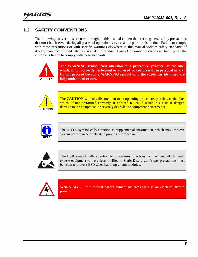
1.2 SAFETY CONVENTIONS
The following conventions are used throughout this manual to alert the user to general safety precautions that must be observed during all phases of operation, service, and repair of this product. Failure to comply with these precautions or with specific warnings elsewhere in this manual violates safety standards of design, manufacture, and intended use of the product. Harris Corporation assumes no liability for the customer's failure to comply with these standards.
The WARNING symbol calls attention to a procedure, practice, or the like, which, if not correctly performed or adhered to, could result in personal injury. Do not proceed beyond a WARNING symbol until the conditions identified are fully understood or met.
CAUTION
The CAUTION symbol calls attention to an operating procedure, practice, or the like, which, if not performed correctly or adhered to, could result in a risk of danger, damage to the equipment, or severely degrade the equipment performance.
The NOTE symbol calls attention to supplemental information, which may improve system performance or clarify a process or procedure.
The ESD symbol calls attention to procedures, practices, or the like, which could expose equipment to the effects of Electro-Static Discharge. Proper precautions must be taken to prevent ESD when handling circuit modules.
WARNING - The electrical hazard symbol indicates there is an electrical hazard present.
MM-011932-001, Rev. A
6
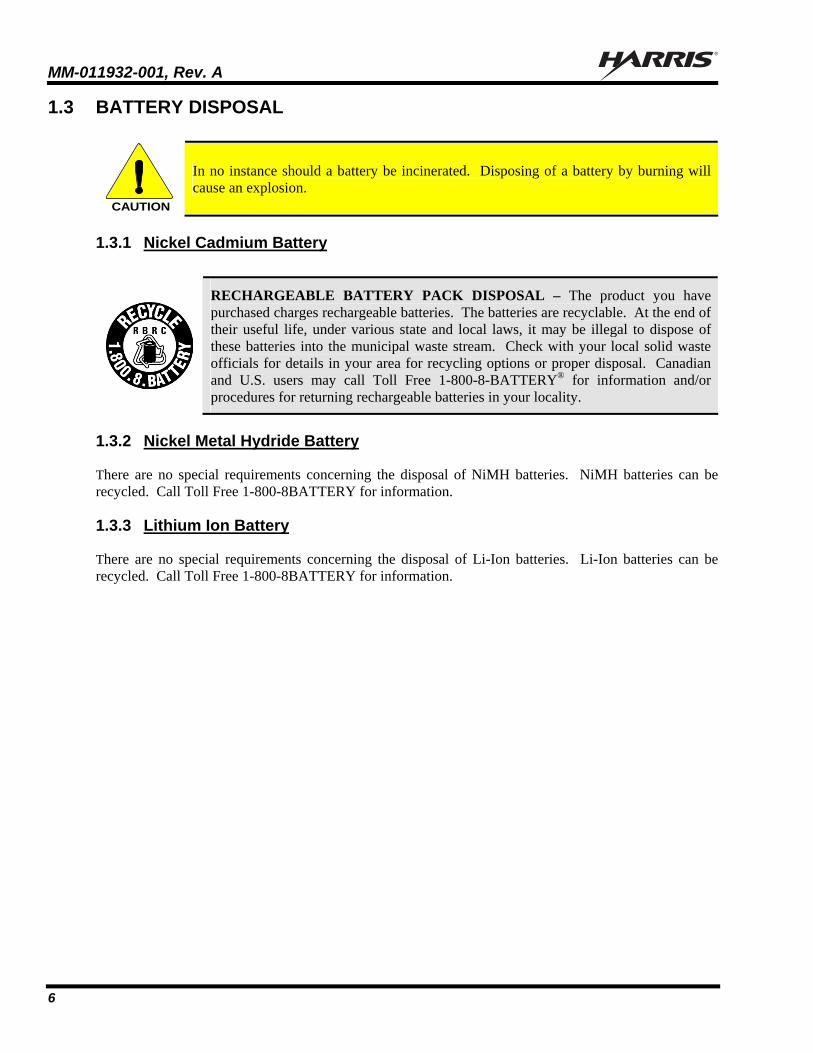
1.3 BATTERY DISPOSAL
CAUTION
In no instance should a battery be incinerated. Disposing of a battery by burning will cause an explosion.
1.3.1 Nickel Cadmium Battery
RECHARGEABLE BATTERY PACK DISPOSAL – The product you have purchased charges rechargeable batteries. The batteries are recyclable. At the end of their useful life, under various state and local laws, it may be illegal to dispose of these batteries into the municipal waste stream. Check with your local solid waste officials for details in your area for recycling options or proper disposal. Canadian and U.S. users may call Toll Free 1-800-8-BATTERY® for information and/or procedures for returning rechargeable batteries in your locality.
1.3.2 Nickel Metal Hydride Battery
There are no special requirements concerning the disposal of NiMH batteries. NiMH batteries can be recycled. Call Toll Free 1-800-8BATTERY for information.
1.3.3 Lithium Ion Battery
There are no special requirements concerning the disposal of Li-Ion batteries. Li-Ion batteries can be recycled. Call Toll Free 1-800-8BATTERY for information.
MM-011932-001, Rev. A
7
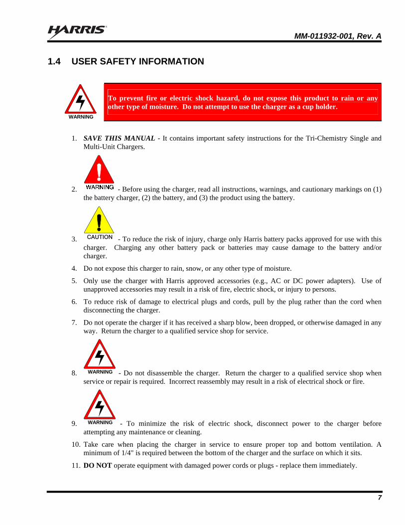
1.4 USER SAFETY INFORMATION
WARNING
To prevent fire or electric shock hazard, do not expose this product to rain or any other type of moisture. Do not attempt to use the charger as a cup holder.
1. SAVE THIS MANUAL - It contains important safety instructions for the Tri-Chemistry Single and Multi-Unit Chargers.
2. - Before using the charger, read all instructions, warnings, and cautionary markings on (1) the battery charger, (2) the battery, and (3) the product using the battery.
3. CAUTION - To reduce the risk of injury, charge only Harris battery packs approved for use with this charger. Charging any other battery pack or batteries may cause damage to the battery and/or charger.
4. Do not expose this charger to rain, snow, or any other type of moisture.
5. Only use the charger with Harris approved accessories (e.g., AC or DC power adapters). Use of unapproved accessories may result in a risk of fire, electric shock, or injury to persons.
6. To reduce risk of damage to electrical plugs and cords, pull by the plug rather than the cord when disconnecting the charger.
7. Do not operate the charger if it has received a sharp blow, been dropped, or otherwise damaged in any way. Return the charger to a qualified service shop for service.
8. WARNING - Do not disassemble the charger. Return the charger to a qualified service shop when service or repair is required. Incorrect reassembly may result in a risk of electrical shock or fire.
9. WARNING - To minimize the risk of electric shock, disconnect power to the charger before attempting any maintenance or cleaning.
10. Take care when placing the charger in service to ensure proper top and bottom ventilation. A minimum of 1/4" is required between the bottom of the charger and the surface on which it sits.
11. DO NOT operate equipment with damaged power cords or plugs - replace them immediately.

MM-011932-001, Rev. A
8
2 INTRODUCTION
This manual provides maintenance instructions for the Tri-Chemistry Single and Multi-Unit chargers, CH-104560 and CH-104570, respectively.
2.1 DESCRIPTION
The Tri-Chemistry Single and Multi-Unit Chargers are designed to charge Harris Corporation Nickel Cadmium (NiCd), Nickel Metal Hydride (NiMH), and Lithium Ion (Li-Ion) batteries used with the P7300, P7200, P7100, P5400, P5300, P5200, and P5100 series portable radios. The Tri-Chemistry Single charger is typically situated on a desk or table top. The Tri-Chemistry Multi-Unit charger can also be placed on a desk or table top, or it can be mounted on a wall (refer to Operator’s Manual MM-011974-001 for mounting instructions). The charger can charge the battery pack with or without being attached to the radio. However, the charger is not designed to charge a transmitting radio. Turn off all radios before placing them into the charger.
This charger is not intended to be used with a transmitting portable radio. Doing so may violate Regulatory compliance.
2.2 FEATURES
The Tri-Chemistry Single and Multi-Unit Chargers provide the following features:
Fast Charge
Auto Discharge Feature
Auto Conditioning for First-Time Ni Chemistry Batteries
Pre-Charge, Rapid Charge, Discharge, Conditioning, Top-Off, Fault, and Ready Indicators (see Figure 2-1.)
Auto-Restart Charging
Adjustable Charge and Trickle Charge Current Settings
120 VAC Power Cord
Backward compatible charger model to accommodate BKB 191 210 series and BT-191210 series batteries
Figure 2-1: Charger Label Legend

MM-011932-001, Rev. A
9
2.3 SPECIFICATIONS
Table 2-1: Single Charger (CH-104560) Specifications
PARAMETER LIMITS
Charging voltage range Ni Chemistry Li Chemistry
6.0V – 11.2V ±5% 6.0 – 8.35V ±0.05V
Charging current 1.5 A ±10% or 1.0 A ±10% (switch selectable)
Trickle Charging Current (NiCd and NiMH)
180 mA ±50 mA or 90 mA ±50 mA (switch selectable)
Discharge Current 1.0A minimum @ 8.6V pack voltage
Operating temperature range 0oC to +45oC (+32oF to +113oF)
Charging temperature range (Start Rapid or Discharge Functions) Ni Chemistry Li Chemistry
+5.0oC to +45oC ±3oC (+41oF to +113oF ±37.4oF) +5.0oC to +40oC ±3oC (+41oF to +104oF ±37.4oF)
Charging temperature range (During Rapid Charge) Ni Chemistry Li Chemistry
0oC to +50oC ±3oC (+32oF to +122oF ±37.4oF) 0oC to +45oC ±3oC (+32oF to +113oF ±37.4oF)
Weight, Single Charger w Sleeve 1.10 lbs (500 g) Weight, Single Charger w Sleeve, Cord, Manual, and Packaging
1.85 lbs. (839 g)
Recharge time NiCd: NiMH: Li-Ion:
Approximately 1 hour Approximately 2 hours Approximately 4 hours
Power consumption 19 Watts MIL-STD-810E standards Low temperature
High temperature Temperature shock Humidity
MM-011932-001, Rev. A
10
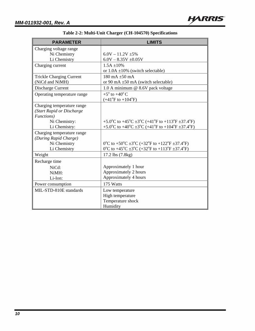
Table 2-2: Multi-Unit Charger (CH-104570) Specifications
PARAMETER LIMITS
Charging voltage range Ni Chemistry Li Chemistry
6.0V – 11.2V ±5% 6.0V – 8.35V ±0.05V
Charging current
1.5A ±10% or 1.0A ±10% (switch selectable)
Trickle Charging Current (NiCd and NiMH)
180 mA ±50 mA or 90 mA ±50 mA (switch selectable)
Discharge Current 1.0 A minimum @ 8.6V pack voltage Operating temperature range +5o to +40o C
(+41oF to +104oF) Charging temperature range (Start Rapid or Discharge Functions) Ni Chemistry: Li Chemistry:
+5.0oC to +45oC ±3oC (+41oF to +113oF ±37.4oF) +5.0oC to +40oC ±3oC (+41oF to +104oF ±37.4oF)
Charging temperature range (During Rapid Charge) Ni Chemistry Li Chemistry
0oC to +50oC ±3oC (+32oF to +122oF ±37.4oF) 0oC to +45oC ±3oC (+32oF to +113oF ±37.4oF)
Weight 17.2 lbs (7.8kg)
Recharge time NiCd: NiMH: Li-Ion:
Approximately 1 hour Approximately 2 hours Approximately 4 hours
Power consumption 175 Watts MIL-STD-810E standards Low temperature
High temperature Temperature shock Humidity
MM-011932-001, Rev. A
11
2.4 CUSTOMER SERVICE
2.4.1 Technical Support
Harris Technical Assistance Center (TAC) resources are available to help you with overall system operation, maintenance, upgrades, and product support. TAC is your point of contact when you need technical questions answered.
Product specialists, with detailed knowledge of product operation, maintenance, and repair, provide technical support via a toll-free telephone number (in North America). Support is also available through mail, fax, and e-mail.
For more information about technical assistance services, contact your sales representative, or call the Technical Assistance Center directly at:
North America: 1-800-528-7711
International: 1-434-385-2400
FAX: 1-434-455-6712
E-mail: [email protected]
MM-011932-001, Rev. A
12
3 CHARGER/SLEEVE COMPATIBILITY (P7100/P5100 & P7200/P5200 Series Radios Only)
The P7300, P5400, and P5300 series portable radios and associated SMART battery products, without exception, are fully supported by the Tri-Chemistry Chargers. The information in this section applies only to the P7200/P5200 and P7100/P5100 series portable radios and the associated batteries.
The P7300, P5400, and P5300 series portable radios and associated SMART battery products, without exception, are fully supported by the Tri-Chemistry Chargers. The information in this section does not apply.
The new Tri-Chemistry charger is the initial phase of a SMART battery and charger program. The SMART battery and charger program is an effort to establish a communication link between the portable radio, its battery, and the charger to allow for optimized portable radio performance. Please refer to the following tables for compatibility/capability information. The following tables are only necessary to determine the compatibility/capability for P7100/P5100 and P7200/P5200 series portable radio and battery products.
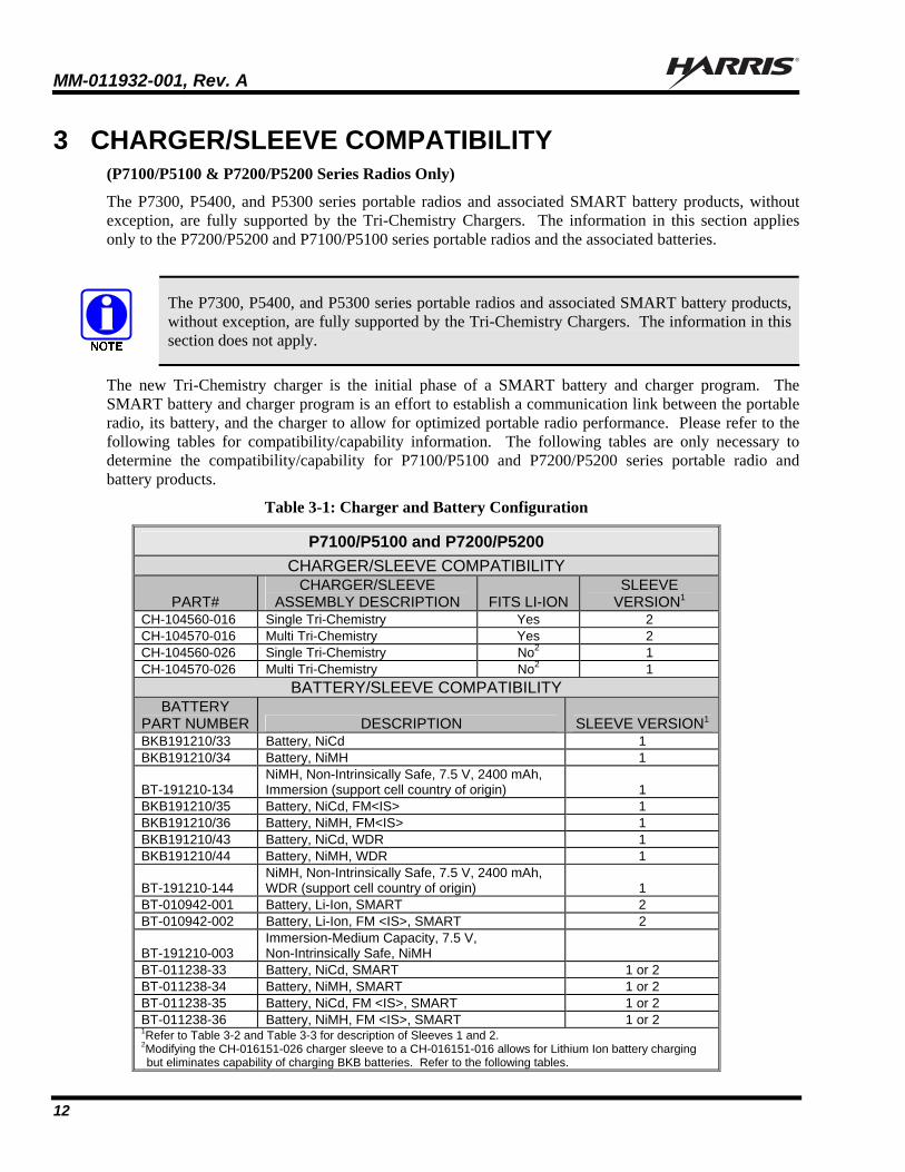
Table 3-1: Charger and Battery Configuration
P7100/P5100 and P7200/P5200
CHARGER/SLEEVE COMPATIBILITY
PART# CHARGER/SLEEVE
ASSEMBLY DESCRIPTION FITS LI-ION SLEEVE
VERSION1 CH-104560-016 Single Tri-Chemistry Yes 2 CH-104570-016 Multi Tri-Chemistry Yes 2 CH-104560-026 Single Tri-Chemistry No2 1 CH-104570-026 Multi Tri-Chemistry No2 1
BATTERY/SLEEVE COMPATIBILITY BATTERY
PART NUMBER DESCRIPTION SLEEVE VERSION1 BKB191210/33 Battery, NiCd 1 BKB191210/34 Battery, NiMH 1
BT-191210-134 NiMH, Non-Intrinsically Safe, 7.5 V, 2400 mAh, Immersion (support cell country of origin) 1
BKB191210/35 Battery, NiCd, FM<IS> 1 BKB191210/36 Battery, NiMH, FM<IS> 1 BKB191210/43 Battery, NiCd, WDR 1 BKB191210/44 Battery, NiMH, WDR 1
BT-191210-144 NiMH, Non-Intrinsically Safe, 7.5 V, 2400 mAh, WDR (support cell country of origin) 1
BT-010942-001 Battery, Li-Ion, SMART 2 BT-010942-002 Battery, Li-Ion, FM <IS>, SMART 2
BT-191210-003 Immersion-Medium Capacity, 7.5 V, Non-Intrinsically Safe, NiMH
BT-011238-33 Battery, NiCd, SMART 1 or 2 BT-011238-34 Battery, NiMH, SMART 1 or 2 BT-011238-35 Battery, NiCd, FM <IS>, SMART 1 or 2 BT-011238-36 Battery, NiMH, FM <IS>, SMART 1 or 2 1Refer to Table 3-2 and Table 3-3 for description of Sleeves 1 and 2. 2Modifying the CH-016151-026 charger sleeve to a CH-016151-016 allows for Lithium Ion battery charging but eliminates capability of charging BKB batteries. Refer to the following tables.

MM-011932-001, Rev. A
13
Table 3-2: Charger, Battery, and Sleeve CH-016151-016
P7100/P5100/P7200/P5200 TRI-CHEMISTRY CHARGER WITH Part # CH-016151-016: SLEEVE VERSION 2 3
Non-SMART Battery Packs(BKB Series & BT-191210)
SMART Battery Packs (BT Series non-191210)
Jumper Position
NiMH NiCd NiMH NiCd Li-Ion
Conditions No No Yes Yes Yes N/A
Charges No No Yes Yes Yes N/A 3 CH-016151-016 (designated Sleeve version 2 in Table 3-2) supports only the BT-011238 and BT-010942 Series battery packs, including Li-Ion battery packs. CH-016151-016 does NOT support BKB series battery packs.
3.1.1 CH-016151-016 Compatibility Summary
CH-016151-016 supports only the BT-011238 and BT-010942 Series battery packs, including Li-Ion battery packs. BKB series and BT-191210 series battery packs are NOT supported by the CH-016151-016 sleeve.
Table 3-3: Charger, Battery, and Sleeve CH-016151-026
P7100/P5100/P7200/P5200 TRI-CHEMISTRY CHARGER USED WITH Part # CH-016151-026: SLEEVE VERSION 1 4
Non-SMART Batteries
(BKB Series) SMART Battery
(BT- Series) Jumper Position
NiMH NiCd NiMH NiCd Li-Ion
Conditions No No No No No Default Pins 2-3
Charges Yes Yes Yes Yes No Default Pins 2-3
Conditions No No Yes Yes No Pins 1-2 Charges Yes No Yes Yes No Pins 1-2 4 CH-016151-026 (designated Sleeve version 1 in Table 3-3) does not support Li-Ion battery packs. It is capable of being modified via jumper position to support the conditioning feature as noted in the table and explained in detail below.
3.1.2 CH-016151-026 Compatibility Summary
If the jumper on Sleeve CH-016151-026 is connected between pins 1 and 2, as it is shipped, the chargers will CHARGE (not condition) both BT-series nickel-based batteries and BKB-series nickel-based batteries. Lithium chemistry battery packs are NOT supported. If the -026 sleeve is modified to connect the jumper between pins 2 and 3, the SMART battery feature is enabled for the BT-series nickel-based battery packs to both charge and condition, but will then only support the charging of the NiMH BKB191210 and BT-191210 battery pack.
MM-011932-001, Rev. A
14
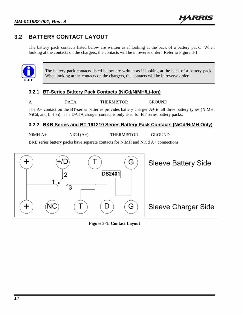
3.2 BATTERY CONTACT LAYOUT
The battery pack contacts listed below are written as if looking at the back of a battery pack. When looking at the contacts on the chargers, the contacts will be in reverse order. Refer to Figure 3-1.
The battery pack contacts listed below are written as if looking at the back of a battery pack. When looking at the contacts on the chargers, the contacts will be in reverse order.
3.2.1 BT-Series Battery Pack Contacts (NiCd/NiMH/Li-Ion)
A+ DATA THERMISTOR GROUND
The A+ contact on the BT-series batteries provides battery charger A+ to all three battery types (NiMH, NiCd, and Li-Ion). The DATA charger contact is only used for BT series battery packs.
3.2.2 BKB Series and BT-191210 Series Battery Pack Contacts (NiCd/NiMH Only)
NiMH A+ NiCd (A+) THERMISTOR GROUND
BKB series battery packs have separate contacts for NiMH and NiCd A+ connections.
Figure 3-1: Contact Layout
MM-011932-001, Rev. A
15
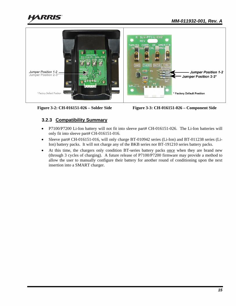
Figure 3-2: CH-016151-026 – Solder Side Figure 3-3: CH-016151-026 – Component Side
3.2.3 Compatibility Summary
P7100/P7200 Li-Ion battery will not fit into sleeve part# CH-016151-026. The Li-Ion batteries will only fit into sleeve part# CH-016151-016.
Sleeve part# CH-016151-016, will only charge BT-010942 series (Li-Ion) and BT-011238 series (Li-Ion) battery packs. It will not charge any of the BKB series nor BT-191210 series battery packs.
At this time, the chargers only condition BT-series battery packs once when they are brand new (through 3 cycles of charging). A future release of P7100/P7200 firmware may provide a method to allow the user to manually configure their battery for another round of conditioning upon the next insertion into a SMART charger.
MM-011932-001, Rev. A
16
4 DIP SWITCH CONFIGURATION/CONTROL
Harris Corporation’s Tri-Chemistry Chargers, models CH-104560 and CH-104570, are microprocessor controlled and use a switching power supply to regulate the charge current/voltage. The charge control microprocessor in the charger reads the pack identification information from the battery memory chip contained in the P7300, P5400, and P5300 portable radio batteries, and establishes the appropriate charge profile for Lithium Ion, Nickel Metal Hydride, or Nickel Cadmium packs.
The microprocessor is programmed during manufacturing and is not intended for general revision. However, provision is provided for service depot level re-programming should it be necessary. The DIP switches are NOT end-user selectable and must be switched at a depot level service shop.
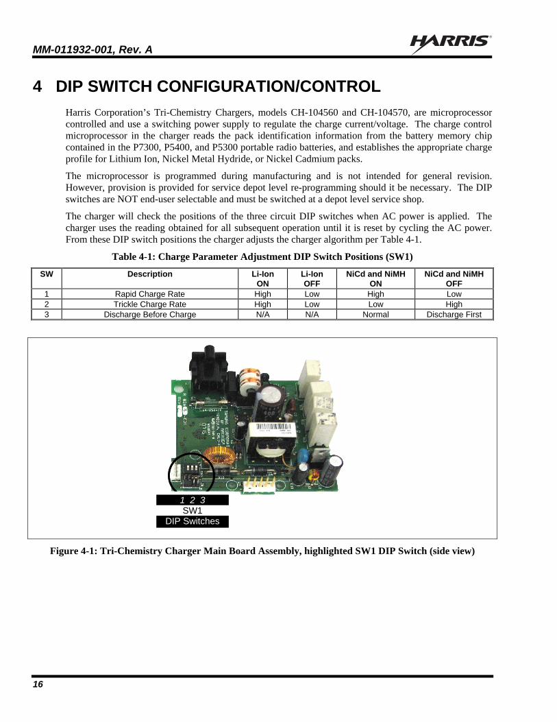
The charger will check the positions of the three circuit DIP switches when AC power is applied. The charger uses the reading obtained for all subsequent operation until it is reset by cycling the AC power. From these DIP switch positions the charger adjusts the charger algorithm per Table 4-1.
Table 4-1: Charge Parameter Adjustment DIP Switch Positions (SW1)
SW Description Li-Ion ON
Li-Ion OFF
NiCd and NiMH ON
NiCd and NiMH OFF
1 Rapid Charge Rate High Low High Low 2 Trickle Charge Rate High Low Low High 3 Discharge Before Charge N/A N/A Normal Discharge First
Figure 4-1: Tri-Chemistry Charger Main Board Assembly, highlighted SW1 DIP Switch (side view)
1 2 3 SW1
DIP Switches
1 2 3 SW1
DIP Switches

MM-011932-001, Rev. A
17
5 PARTS LIST
All components in the following parts list are for reference only or are considered common parts available from your local electronic parts distributor.
5.1 MULTI-CHARGER PARTS LIST: R8264-C01B, REV. B
REF DES
DESCRIPTION
CAPACITORS C12 Capacitor, 10µF 25V C13 Capacitor, 10µF 25V C15 Capacitor, 470pF C16 Capacitor, 0.47µF, 16V C17 Capacitor, 0.001µF C18 Capacitor, 0.1µF C19 Capacitor, 0.01µF C20 Capacitor, 0.1µF C21 Capacitor, 0.001µF C22 Capacitor, 0.001µF C23 Capacitor, 0.1µF C25 Capacitor, 0.1µF C26 Capacitor, 0.1µF
DIODES D11 Diode, Rectifier Diode, 100V, CMPD4448 D12 Diode, Rectifier Diode, 100V, CMPD4448 D13 Diode, Zener 12V, 1/2W Z1 Diode, Zener 5.1V
RESISTORS R10 Resistor, 130 kohms, 1% R11 Resistor, 100 kohms, 1% R17 Resistor, 100 ohms, 1% R18 Resistor, 0.10 ohms, 1W R19 Resistor, 10.0 ohms, 1% R21 Resistor, 1.33 kohms, ¼ R20 Resistor, 1.50 kohms, 1% R22 Resistor, 1.82 kohms, 1% R23 Resistor, 20.0 kohms, 1% R24 Resistor, 10.0 kohms, 1% R25 Resistor, 20.0 kohms, 1% R26 Resistor, 20.0 kohms, 1% R27 Resistor, 39 kohms R28 Resistor, 24 kohms, .1% R29 Resistor, 1.21 kohms, 1% R30 Resistor, 20.0 kohms, 1% R32 Resistor, 3.01 kohms, 1% R34 Resistor, 619 ohms, 1% R35 Resistor, 1.00 kohms, 1% R36 Resistor, 1.30 kohms, 1%
REF DES
DESCRIPTION
R37 Resistor, 619 ohms, 1% R38 Resistor, 24.3 kohms, 1% R39 Resistor, 47.5 kohms, 1% R40 Resistor, 10.0 kohms, 1% R41 Resistor, 1.33 kohms, ¼ R42 Resistor, 1.33 kohms, ¼ R43 Resistor, 1.33 kohms, ¼ R44 Resistor, 1.00 kohms, 1% R45 Resistor, 47.5 kohms, 1% R46 Resistor, 1.82 kohms, 1% R47 Resistor, 1.82 kohms, 1% R48 Resistor, 1.82 kohms, 1% R49 Resistor, 47.5 kohms, 1% R50 Resistor, 47.5 kohms, 1% R51 Resistor, 47.5 kohms, 1% R52 Resistor, 47.5 kohms, 1% R53 Resistor, 47.5 kohms, 1% R54 Resistor, 475 kohms, 1% R57 Resistor, 3.01 kohms, 1%
TRANSISTORS Q2 Transistor, P-MOSFET, 30V, 5A Q3 Transistor, P-Channel 60V (D-S) MOSFET,
TP061OK SOT-23 Q4 Transistor, 500mA, 80V, NPN Q5 Transistor, N-Channel Enhancement Mode Field
Effect Transistor, 60V, 800mA, 2N7002 Q6 Transistor, N-Channel Enhancement Mode Field
Effect Transistor, 60V, 800mA, 2N7002K INTEGRATED CIRCUITS
U4 IC E-PROM –Based 8-Bit CMOS Microcontroller,PIC16H PROG

MM-011932-001, Rev. A
18
5.2 MULTI-CHARGER PARTS LIST: R8264-C01, REV B1
REF DES
DESCRIPTION
CAPACITORS C10 Capacitor, 220µF, 35V
INDUCTORS
L3 Choke,
CONNECTORS J2 Connector, 2 Circuits J3 Connector, 5 Circuit Hdr J4 Connector, 8 Circuits Dual Row J5 Connector, 4 Circuits with Lock
REF DES
DESCRIPTION
Jumper, 2 Circuits Dual
DIODES D9 Diode, 3A, 40V Schottky
D10 Diode, 3A, 40V Schottky
TRANSISTORS Q1 Transistor, FET 9.0A 60V N-Channel
RESISTORS R12 Resistor, 30 ohms, 5W R13 Resistor, 30 ohms, 5W R14 Resistor, 30 ohms, 5W R15 Resistor, 30 ohms, 5W
SWITCHES SW1 Switch, Dipswitch, 3 Position
5.3 SINGLE CHARGER PARTS LIST: R8263-C01, REV. C
REF DES
DESCRIPTION
CAPACITORS C1 Capacitor, 0.1 µF, 250V C2 Capacitor, 0.1 µF, 400V C3 Capacitor, 68 µF, 400V C4 Capacitor, 0.001 µF, 500V C5 Capacitor, 47 µF, 25V C8 Capacitor, 2.2 nF, 250V C9 Capacitor, 470, 25V
C10 Capacitor, 220 µF, 35V
DIODES D1 Diode, 1A, 1000V D2 Diode, 1A, 1000V D3 Diode, 1A, 1000V D4 Diode, 1A, 1000V D5 Diode, 1A, 1000V D7 Diode, 10A, 100V D9 Diode, 3A, 40V, Schottky
D10 Diode, 3A, 40V, Schottky
FUSES F1 Fuse, 1.6A
CONNECTORS J1 Receptacle, AC Inlet 2 Circuit J3 Connector, 5 Circuit Header Gold J4 Connector, 8 Circuits Dual Row J5 Connector, 4 Circuits with Lock Jumper, 2 Circuits Dual
INDUCTORS L1 Inductor, 18 mH, 0.5A L2 Choke L3 Choke
TRANSISTORS
Q1 Transistor, FET, 9.0A, 60V, N-Channel
RESISTORS R3 Resistor, 82 kohms, 2WM, 5%
R12 Resistor, 30 ohms, 5W R13 Resistor, 30 ohms, 5W R14 Resistor, 30 ohms, 5W R15 Resistor, 30 ohms, 5W RT1 Thermistor, 4 ohms, 3A
SWITCHES
SW1 Switch, 3 Position Dip Switch
INDUCTORS T1 Transformer,
INTEGRATED CIRCUITS
U1 IC, 26W U2 IC, Optocoupler, PS2561L1, 4PN
VARISTORS
VR1 Varistor, 5A, 430V VR2 Transorb, 200V, 2.1A, 600W
MM-011932-001, Rev. A
19
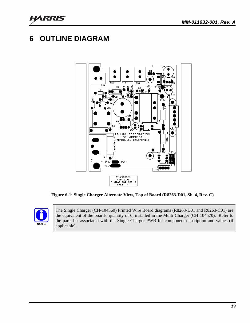
6 OUTLINE DIAGRAM
Figure 6-1: Single Charger Alternate View, Top of Board (R8263-D01, Sh. 4, Rev. C)
The Single Charger (CH-104560) Printed Wire Board diagrams (R8263-D01 and R8263-C01) are the equivalent of the boards, quantity of 6, installed in the Multi-Charger (CH-104570). Refer to the parts list associated with the Single Charger PWB for component description and values (if applicable).

MM-011932-001, Rev. A
20
Figure 6-2: Single Charger PWB, R8263-C01, Sh. 3, Rev. B

MM-011932-001, Rev. A
21
Figure 6-3: Sleeve PWB (shown here CH-016151-007 [RSLV-P53-S-CO2, Rev. A])
MM-011932-001, Rev. A
22
This page intentionally left blank.
MM-011932-001, Rev. A
23
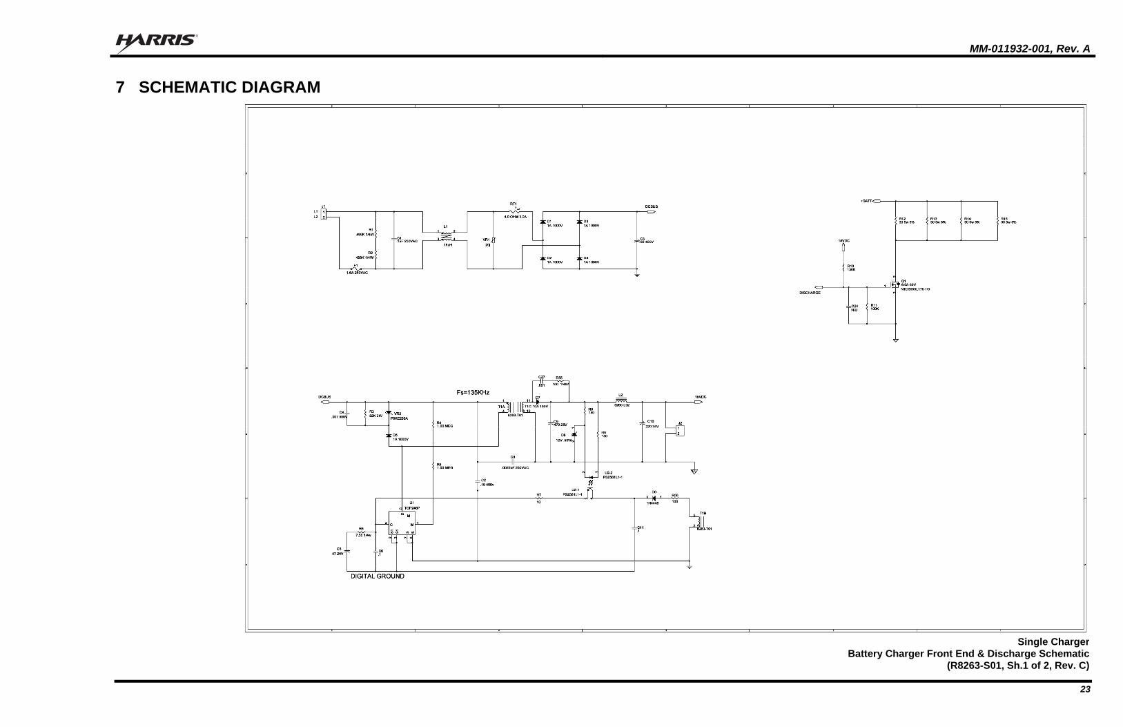
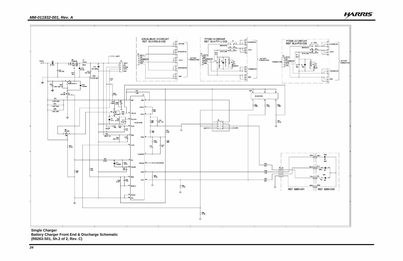
7 SCHEMATIC DIAGRAM
Single Charger
Battery Charger Front End & Discharge Schematic(R8263-S01, Sh.1 of 2, Rev. C)
MM-011932-001, Rev. A
24
Single Charger Battery Charger Front End & Discharge Schematic (R8263-S01, Sh.2 of 2, Rev. C)

MM-011932-001, Rev. A
25
Multi-ChargerSystem Schematic
(R8264-S01, Rev. A)
MM-011932-001, Rev. A
26
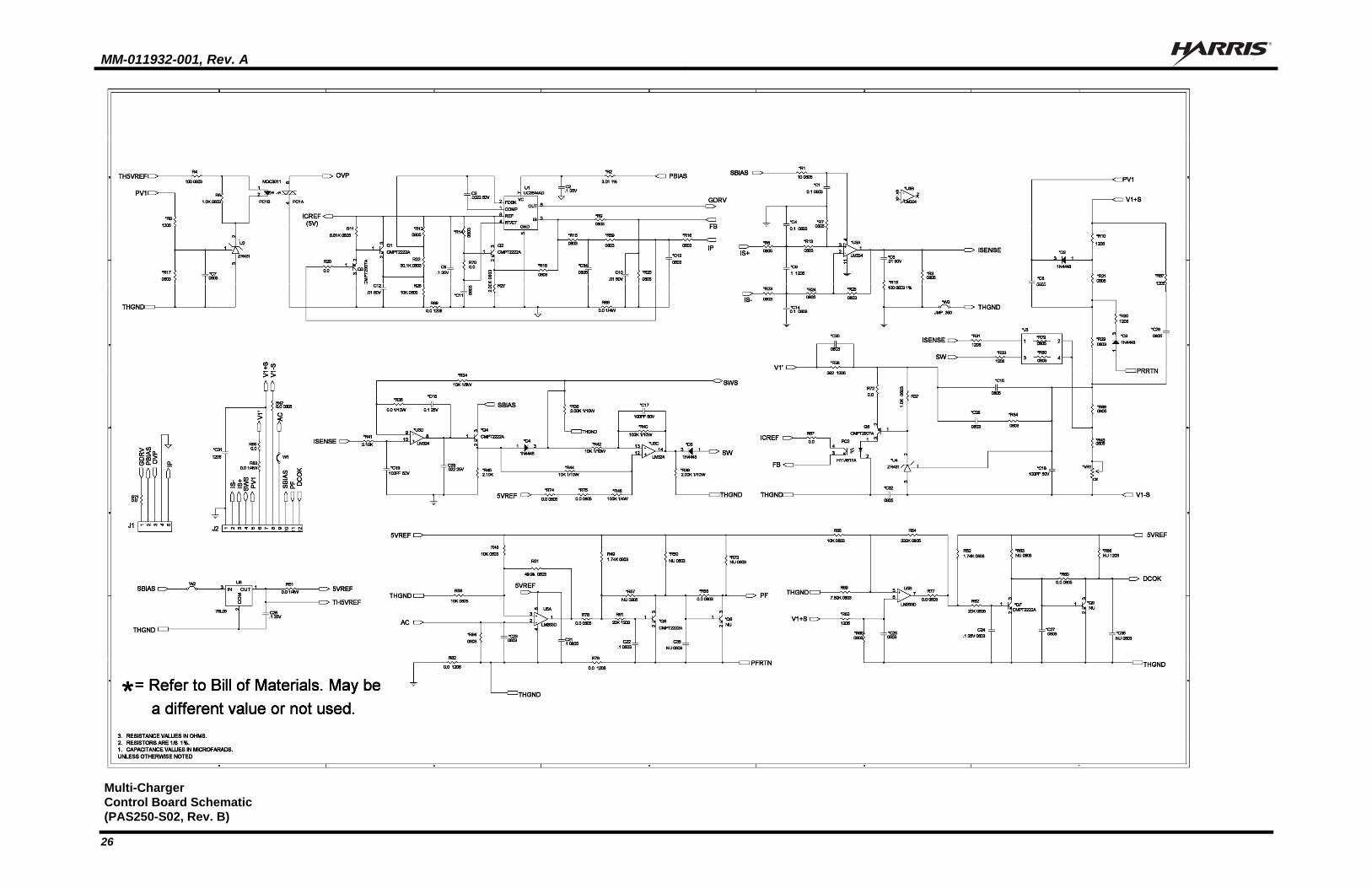
Multi-Charger
Control Board Schematic (PAS250-S02, Rev. B)
MM-011932-001, Rev. A
27
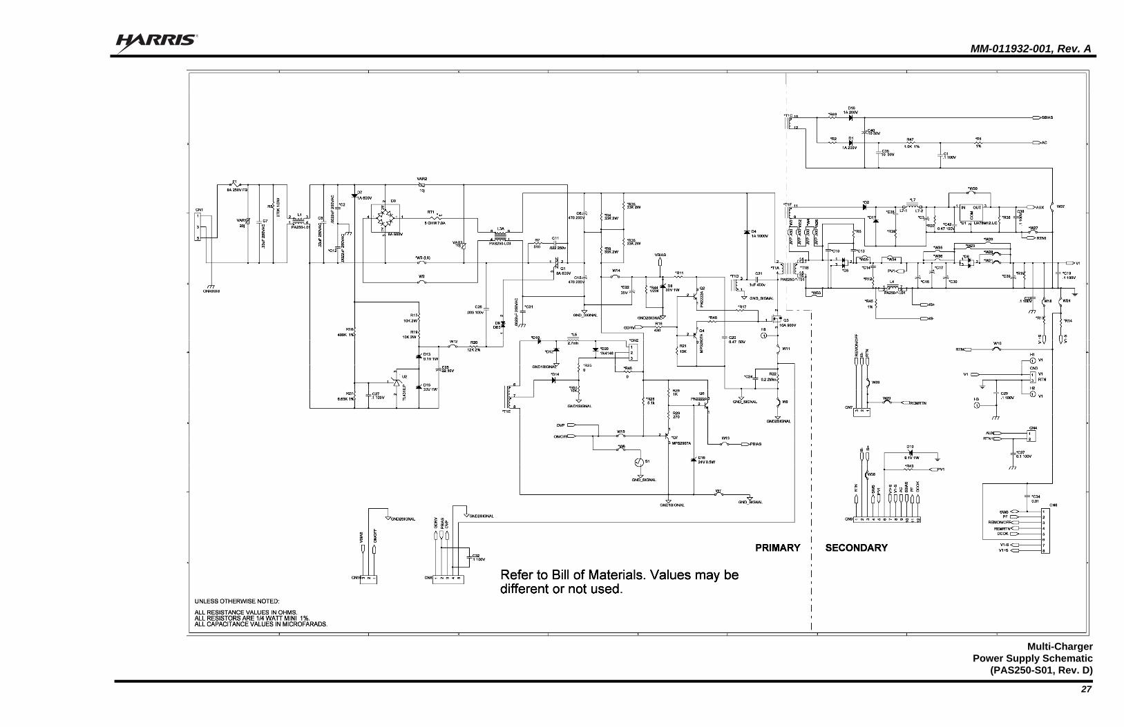
Multi-Charger
Power Supply Schematic(PAS250-S01, Rev. D)
MM-011932-001, Rev. A
28
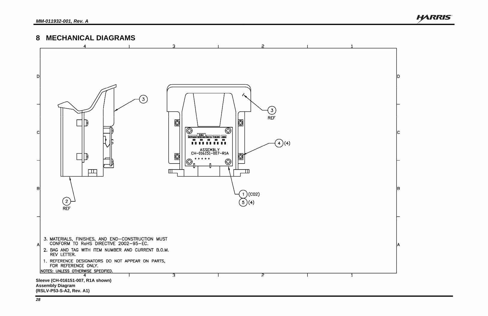
8 MECHANICAL DIAGRAMS
Sleeve (CH-016151-007, R1A shown)
Assembly Diagram (RSLV-P53-S-A2, Rev. A1)
MM-011932-001, Rev. A
29
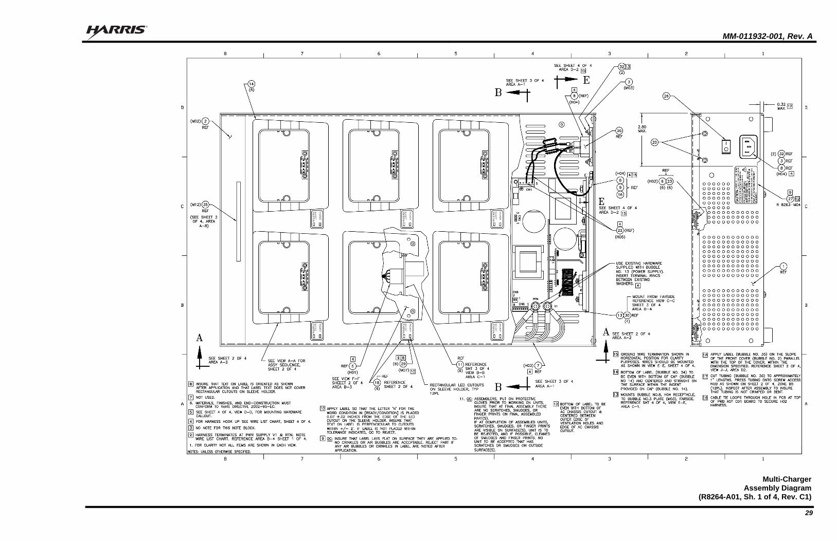
Multi-ChargerAssembly Diagram
(R8264-A01, Sh. 1 of 4, Rev. C1)
MM-011932-001, Rev. A
30
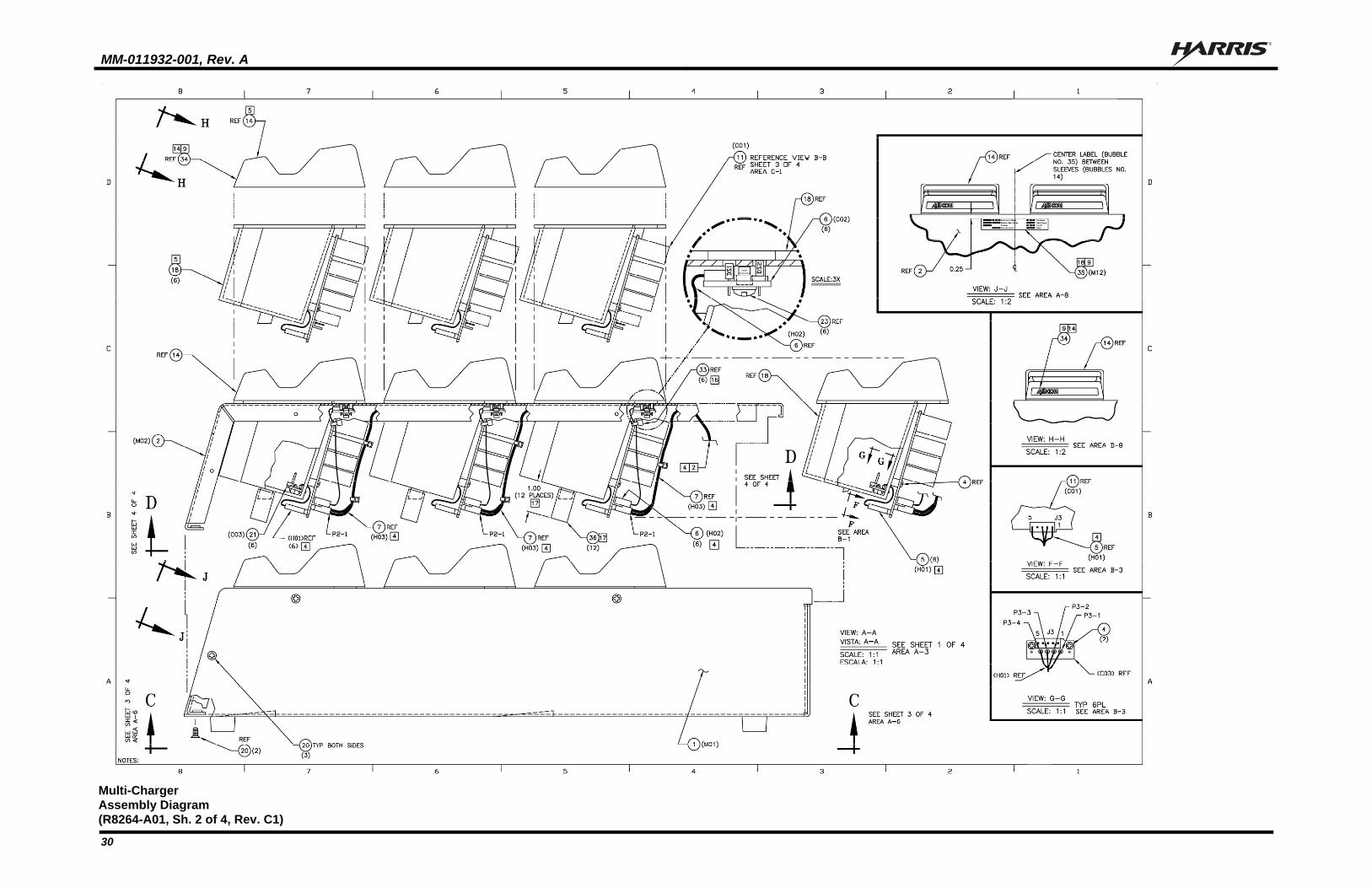
Multi-Charger Assembly Diagram (R8264-A01, Sh. 2 of 4, Rev. C1)
MM-011932-001, Rev. A
31
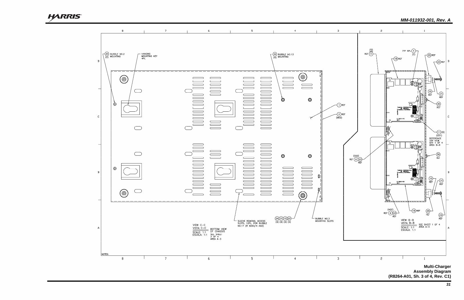
Multi-ChargerAssembly Diagram
(R8264-A01, Sh. 3 of 4, Rev. C1)
MM-011932-001, Rev. A
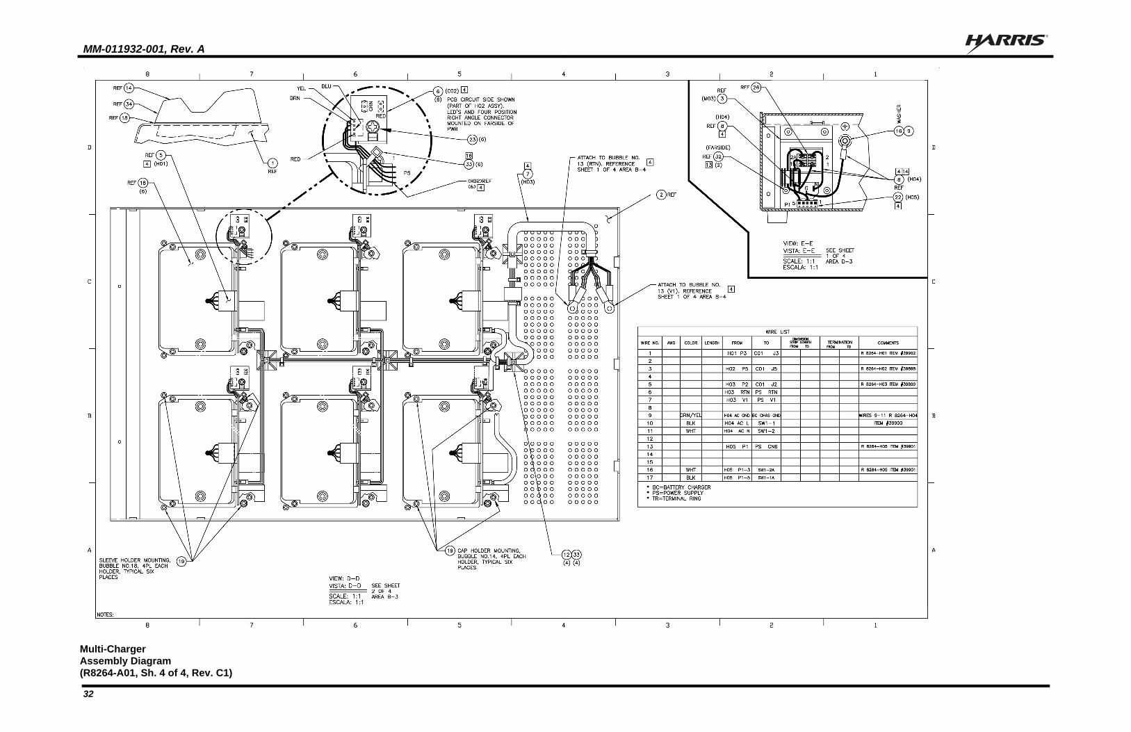
32
Multi-Charger Assembly Diagram (R8264-A01, Sh. 4 of 4, Rev. C1)

MM-011932-001, Rev. A
33
This page intentionally left blank.

Public Safety and Professional Communications | www.harrispublicsafety.com221 Jefferson Ridge Parkway | Lynchburg, VA USA 24501 | 1-800-528-7711