mk2 n1mm logger+ setup - microham_setup.pdf · microkeyer ii and n1mm logger+ setup router setup:...
TRANSCRIPT
micro KEYER II and N1MM Logger+ Setup
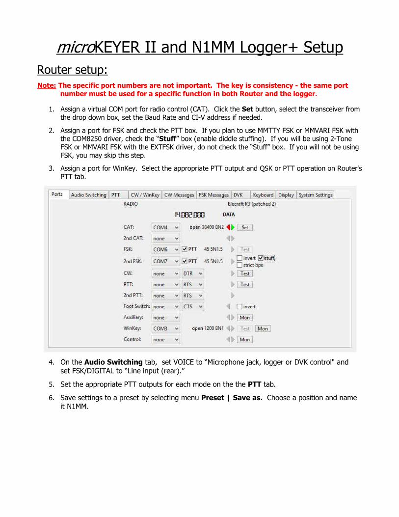
Router setup:Note: The specific port numbers are not important. The key is consistency - the same port
number must be used for a specific function in both Router and the logger.
1. Assign a virtual COM port for radio control (CAT). Click the Set button, select the transceiver from the drop down box, set the Baud Rate and CI-V address if needed.
2. Assign a port for FSK and check the PTT box. If you plan to use MMTTY FSK or MMVARI FSK with the COM8250 driver, check the “Stuff” box (enable diddle stuffing). If you will be using 2-Tone FSK or MMVARI FSK with the EXTFSK driver, do not check the “Stuff” box. If you will not be using FSK, you may skip this step.
3. Assign a port for WinKey. Select the appropriate PTT output and QSK or PTT operation on Router'sPTT tab.
4. On the Audio Switching tab, set VOICE to “Microphone jack, logger or DVK control" and set FSK/DIGITAL to “Line input (rear).”
5. Set the appropriate PTT outputs for each mode on the the PTT tab.
6. Save settings to a preset by selecting menu Preset | Save as. Choose a position and name it N1MM.
N1MM hardware setup:
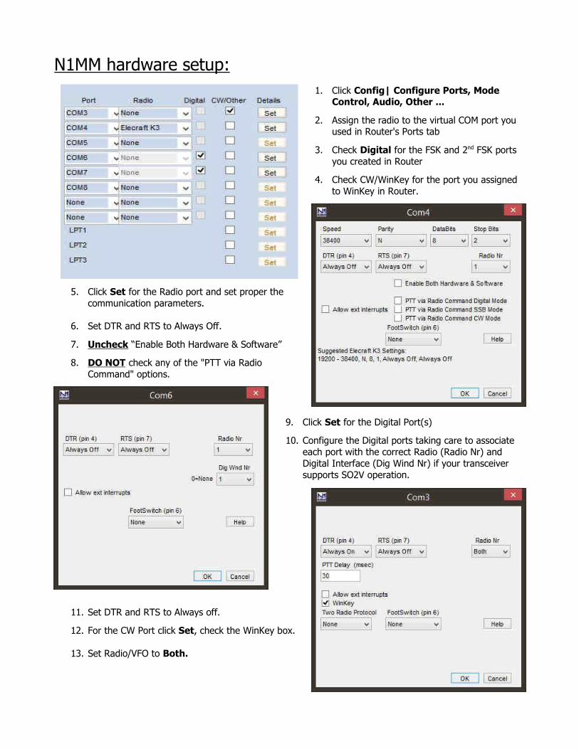
1. Click Config| Configure Ports, Mode Control, Audio, Other ...
2. Assign the radio to the virtual COM port you used in Router's Ports tab
3. Check Digital for the FSK and 2nd FSK ports
you created in Router
4. Check CW/WinKey for the port you assigned
to WinKey in Router.
5. Click Set for the Radio port and set proper the
communication parameters.
6. Set DTR and RTS to Always Off.
7. Uncheck “Enable Both Hardware & Software”
8. DO NOT check any of the "PTT via Radio
Command" options.
9. Click Set for the Digital Port(s)
10. Configure the Digital ports taking care to associate
each port with the correct Radio (Radio Nr) and
Digital Interface (Dig Wind Nr) if your transceiver
supports SO2V operation.
11. Set DTR and RTS to Always off.
12. For the CW Port click Set, check the WinKey box.
13. Set Radio/VFO to Both.
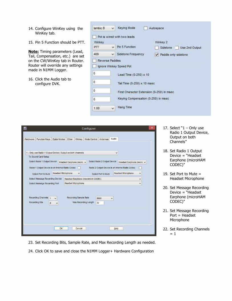
14. Configure WinKey using the
WinKey tab.
15. Pin 5 Function should be PTT.
Note: Timing parameters (Lead,
Tail, Compensation, etc.) are set
on the CW/WinKey tab in Router.Router will override any settings
made in N1MM Logger.
16. Click the Audio tab to
configure DVK.
17. Select “1 – Only use Radio 1 Output Device,
Output on both
Channels”
18. Set Radio 1 Output
Device = “Headset Earphone (microHAM
CODEC)”
19. Set Port to Mute =
Headset Microphone
20. Set Message Recording
Device = “Headset
Earphone (microHAM
CODEC)”
21. Set Message Recording Port = Headset
Microphone
22. Set Recording Channels
= 1
23. Set Recording Bits, Sample Rate, and Max Recording Length as needed.
24. Click OK to save and close the N1MM Logger+ Hardware Configuration

MMTTY FSK setup:
N1MM Logger Plus supports the MMTTY Engine, MMVARI, 2-Tone and/or an external TNC for RTTY contesting. This configuration is based on using MMTTY in FSK mode.
1. Install MMTTY.
2. Note: If your radio supports dual receiver (SO2V) operation, you may want to install MMTTY to two different directories on your hard disk.
3. Select the Digital Modes tab in Configure Ports, Mode Control, Audio, Other ...
4. Set TU Type to Soundcard
5. Select FSK as the MMTTY mode for DI-1 and DI-2 if using SO2V.
6. Enter the path to each MMTTY installation.
7. Open the Mode Control tab
8. Select the method to determinethe mode to log.
9. Set the appropriate RTTY andPSK modes for your transceiver. .
Note: See the N1MM Logger Helpfiles for the supported RTTY and PSK modes for each transceiver.
10. Click "OK" to save the settings and close the Mode Control.
11. Activate the left Entry Window (Radio 1) and Enter RTTY to open DI 1.
12. If this is the first time you have used the MMTTY interface, click on Interface | MMTTY to activate the MMTTY interface.
13. In the Digital Interface, Click Setup | Setup MMTTY.
14. Select the "SoundCard" tab.
15. Select “Line (microHAM CODEC) for Reception.
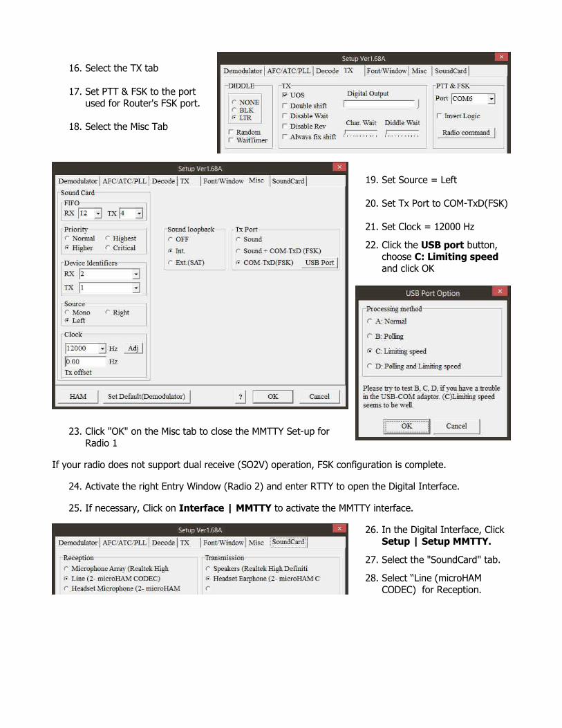
16. Select the TX tab
17. Set PTT & FSK to the portused for Router's FSK port.
18. Select the Misc Tab
19. Set Source = Left
20. Set Tx Port to COM-TxD(FSK)
21. Set Clock = 12000 Hz
22. Click the USB port button, choose C: Limiting speed and click OK
23. Click "OK" on the Misc tab to close the MMTTY Set-up forRadio 1
If your radio does not support dual receive (SO2V) operation, FSK configuration is complete.
24. Activate the right Entry Window (Radio 2) and enter RTTY to open the Digital Interface.
25. If necessary, Click on Interface | MMTTY to activate the MMTTY interface.
26. In the Digital Interface, Click Setup | Setup MMTTY.
27. Select the "SoundCard" tab.
28. Select “Line (microHAM CODEC) for Reception.
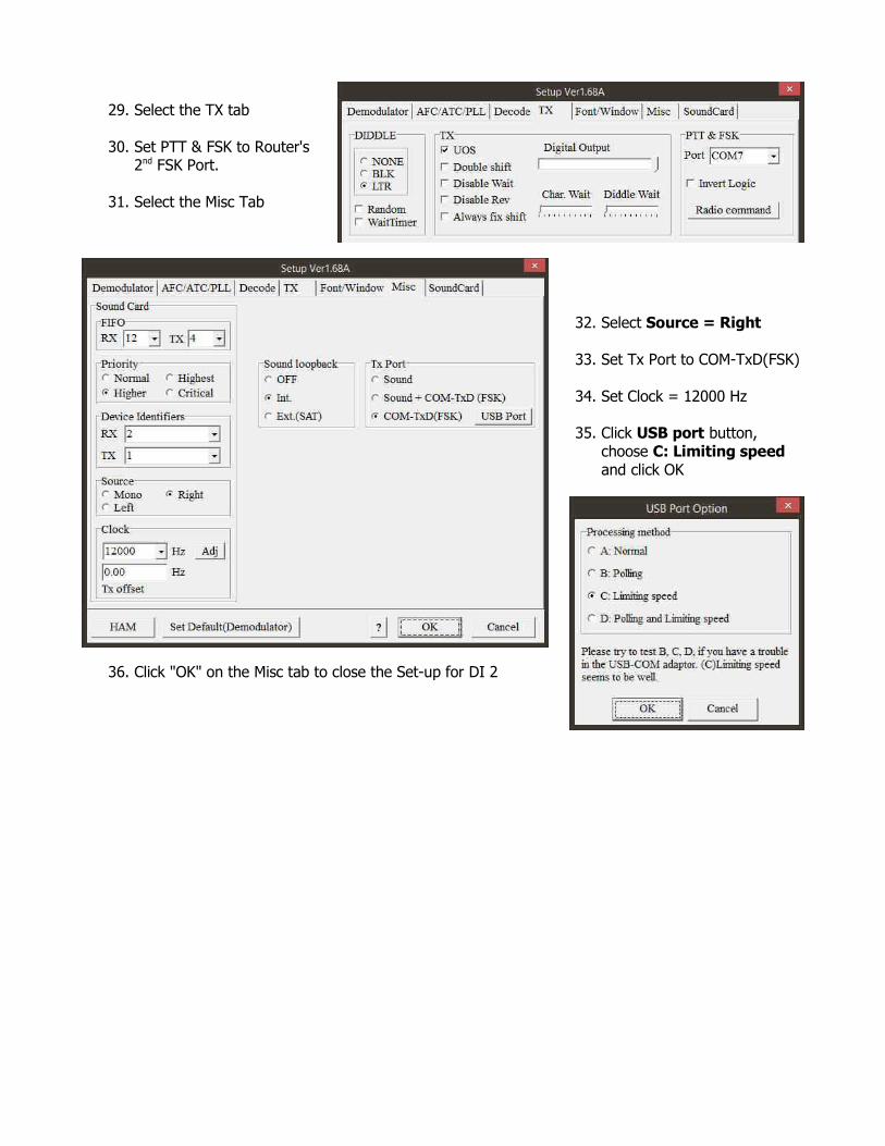
29. Select the TX tab
30. Set PTT & FSK to Router's2nd FSK Port.
31. Select the Misc Tab
32. Select Source = Right
33. Set Tx Port to COM-TxD(FSK)
34. Set Clock = 12000 Hz
35. Click USB port button, choose C: Limiting speed and click OK
36. Click "OK" on the Misc tab to close the Set-up for DI 2
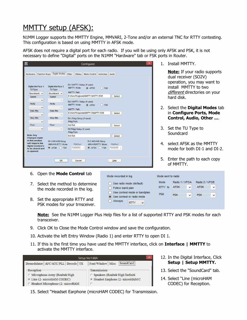
MMTTY setup (AFSK):N1MM Logger supports the MMTTY Engine, MMVARI, 2-Tone and/or an external TNC for RTTY contesting. This configuration is based on using MMTTY in AFSK mode.
AFSK does not require a digital port for each radio. If you will be using only AFSK and PSK, it is not necessary to define "Digital" ports on the N1MM "Hardware" tab or FSK ports in Router.
1. Install MMTTY.
Note: If your radio supports dual receiver (SO2V) operation, you may want to install MMTTY to two different directories on your hard disk.
2. Select the Digital Modes tabin Configure Ports, Mode Control, Audio, Other ....
3. Set the TU Type to Soundcard
4. select AFSK as the MMTTY mode for both DI-1 and DI-2.
5. Enter the path to each copy of MMTTY.
6. Open the Mode Control tab
7. Select the method to determinethe mode recorded in the log.
8. Set the appropriate RTTY andPSK modes for your trnsceiver.
Note: See the N1MM Logger Plus Help files for a list of supported RTTY and PSK modes for each transceiver.
9. Click OK to Close the Mode Control window and save the configuration.
10. Activate the left Entry Window (Radio 1) and enter RTTY to open DI 1.
11. If this is the first time you have used the MMTTY interface, click on Interface | MMTTY to activate the MMTTY interface.
12. In the Digital Interface, Click Setup | Setup MMTTY.
13. Select the "SoundCard" tab.
14. Select “Line (microHAM CODEC) for Reception.
15. Select “Headset Earphone (microHAM CODEC) for Transmission.
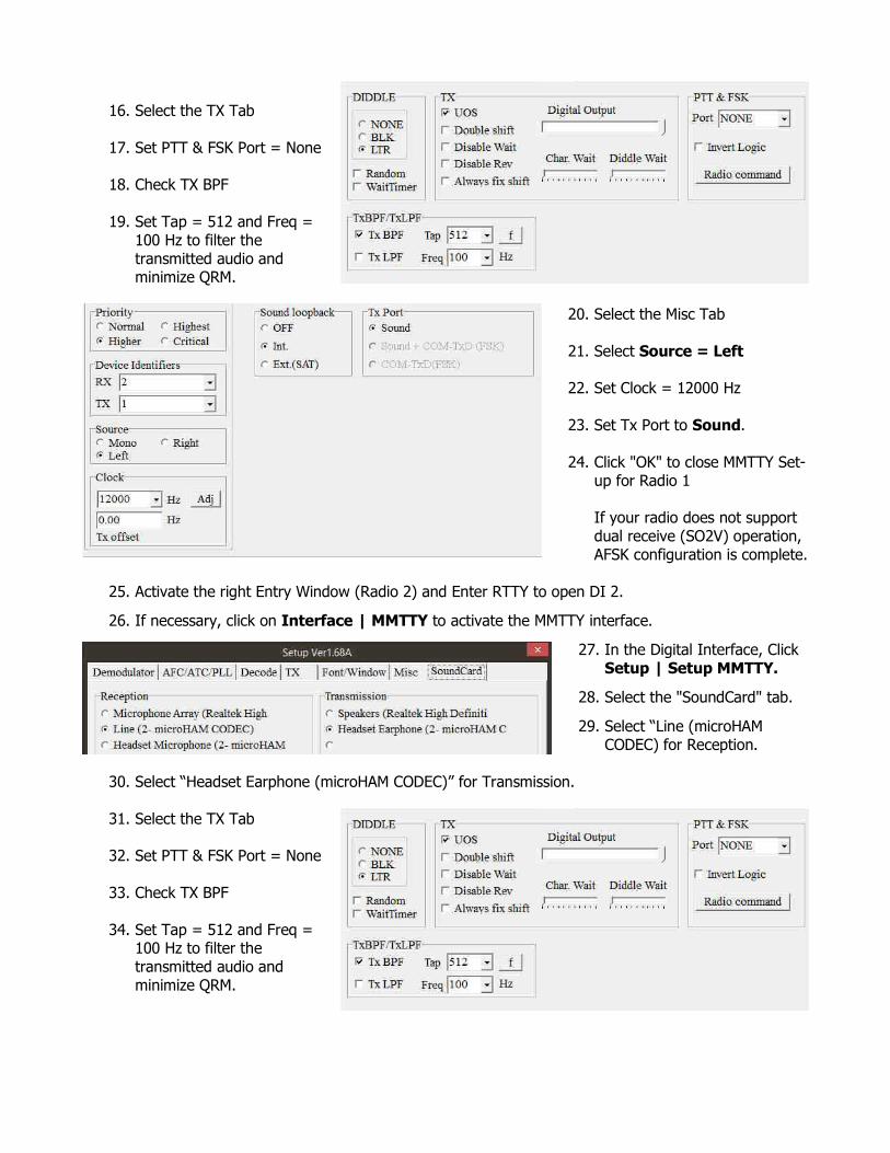
16. Select the TX Tab
17. Set PTT & FSK Port = None
18. Check TX BPF
19. Set Tap = 512 and Freq =100 Hz to filter thetransmitted audio andminimize QRM.
20. Select the Misc Tab
21. Select Source = Left
22. Set Clock = 12000 Hz
23. Set Tx Port to Sound.
24. Click "OK" to close MMTTY Set-up for Radio 1
If your radio does not support dual receive (SO2V) operation, AFSK configuration is complete.
25. Activate the right Entry Window (Radio 2) and Enter RTTY to open DI 2.
26. If necessary, click on Interface | MMTTY to activate the MMTTY interface.
27. In the Digital Interface, Click Setup | Setup MMTTY.
28. Select the "SoundCard" tab.
29. Select “Line (microHAM CODEC) for Reception.
30. Select “Headset Earphone (microHAM CODEC)” for Transmission.
31. Select the TX Tab
32. Set PTT & FSK Port = None
33. Check TX BPF
34. Set Tap = 512 and Freq =100 Hz to filter thetransmitted audio andminimize QRM.

35. Select the Misc Tab
36. Select Source = Right
37. Set Clock = 12000 Hz
38. Set Tx Port to Sound
39. Click "OK" to close MMTTY Setup for Radio 2.

MMVARI Setup with FSK:N1MM Logger supports the MMTTY Engine, MMVARI, 2-Tone and/or an external TNC for RTTY contesting. This configuration is for FSK RTTY and PSK with MMVARI.
FSK requires a digital port for each receiver (DI). Be sure you have defined Digital ports for each DI in the N1MM "Hardware" tab and FSK ports in Router.
1. Select the Digital Modes tab in Configure Ports, Mode Control, Audio, Other ....
2. Set the TU Type to Soundcard
3. select FSK as the MMVARI RTTY mode for both DI-1 and DI-2.
4. Set the FSK Port to FSK8250for both DI-1 and DI-2
5. Open the Mode Control tab
6. Open the Mode Control tab
7. Select the method to determinethe mode to log.
8. Set the appropriate RTTY andPSK modes for your transceiver.
Note: See the N1MM LoggerPlus Help files for the supported RTTY and PSK modes for each transceiver.
9. Click "OK" to save the settings and close the Mode Control.
10. Activate the left Entry Window (Radio 1) and enter PSK.
11. Click Setup | Settings and select MMVARI as the Default RTTY Interface and MMVARI as the Default PSK Interface.
12. Select MMVARI Setup.
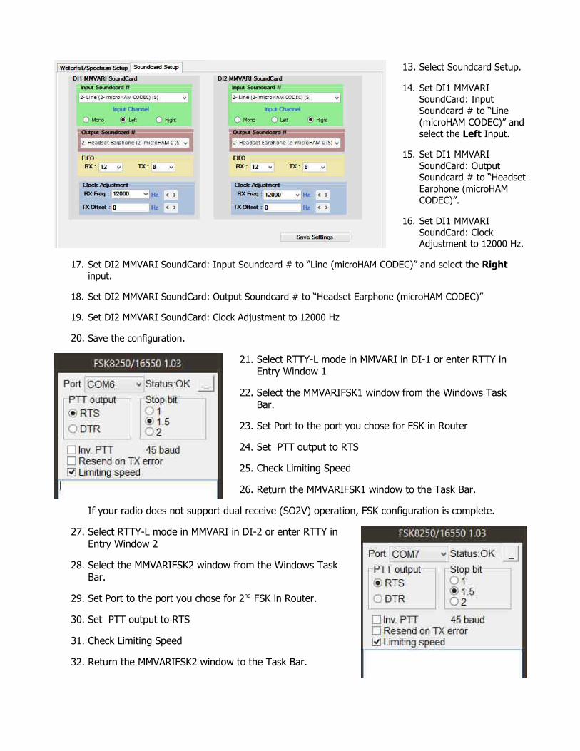
13. Select Soundcard Setup.
14. Set DI1 MMVARI SoundCard: Input
Soundcard # to “Line
(microHAM CODEC)” and
select the Left Input.
15. Set DI1 MMVARI
SoundCard: Output
Soundcard # to “Headset
Earphone (microHAM CODEC)”.
16. Set DI1 MMVARI
SoundCard: Clock Adjustment to 12000 Hz.
17. Set DI2 MMVARI SoundCard: Input Soundcard # to “Line (microHAM CODEC)” and select the Right input.
18. Set DI2 MMVARI SoundCard: Output Soundcard # to “Headset Earphone (microHAM CODEC)”
19. Set DI2 MMVARI SoundCard: Clock Adjustment to 12000 Hz
20. Save the configuration.
21. Select RTTY-L mode in MMVARI in DI-1 or enter RTTY in Entry Window 1
22. Select the MMVARIFSK1 window from the Windows Task Bar.
23. Set Port to the port you chose for FSK in Router
24. Set PTT output to RTS
25. Check Limiting Speed
26. Return the MMVARIFSK1 window to the Task Bar.
If your radio does not support dual receive (SO2V) operation, FSK configuration is complete.
27. Select RTTY-L mode in MMVARI in DI-2 or enter RTTY inEntry Window 2
28. Select the MMVARIFSK2 window from the Windows TaskBar.
29. Set Port to the port you chose for 2nd FSK in Router.
30. Set PTT output to RTS
31. Check Limiting Speed
32. Return the MMVARIFSK2 window to the Task Bar.
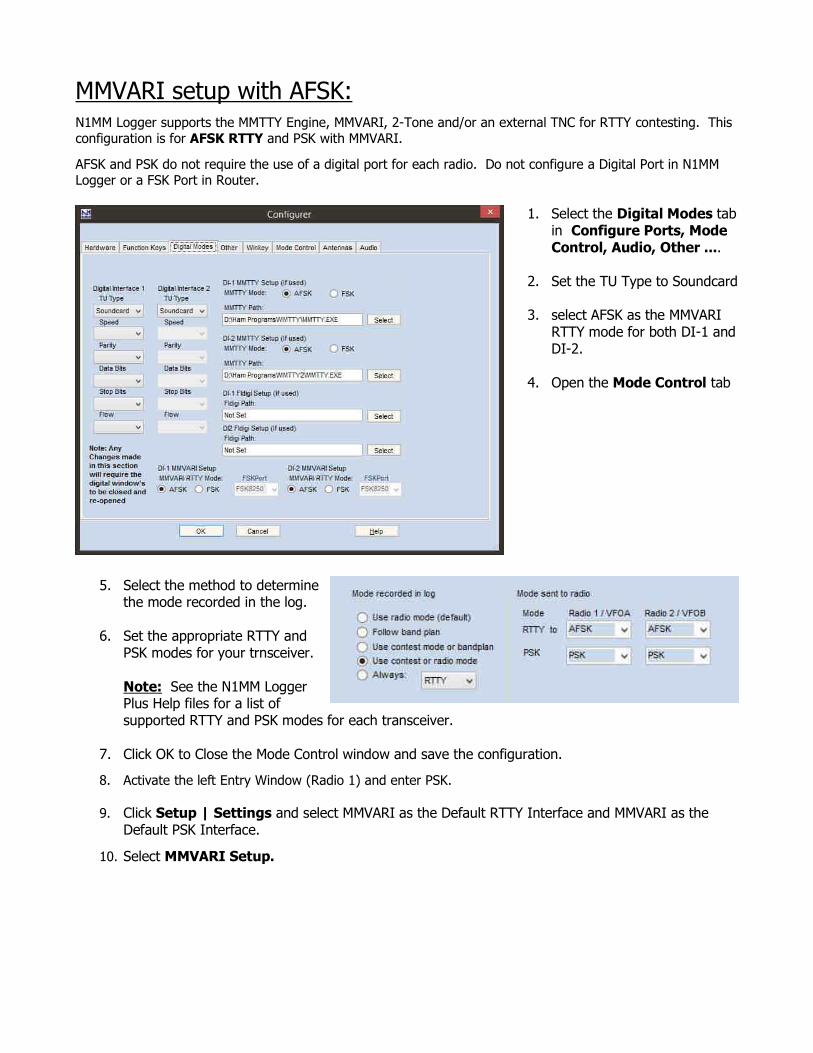
MMVARI setup with AFSK:N1MM Logger supports the MMTTY Engine, MMVARI, 2-Tone and/or an external TNC for RTTY contesting. This configuration is for AFSK RTTY and PSK with MMVARI.
AFSK and PSK do not require the use of a digital port for each radio. Do not configure a Digital Port in N1MM Logger or a FSK Port in Router.
1. Select the Digital Modes tabin Configure Ports, Mode Control, Audio, Other ....
2. Set the TU Type to Soundcard
3. select AFSK as the MMVARI RTTY mode for both DI-1 andDI-2.
4. Open the Mode Control tab
5. Select the method to determinethe mode recorded in the log.
6. Set the appropriate RTTY andPSK modes for your trnsceiver.
Note: See the N1MM LoggerPlus Help files for a list ofsupported RTTY and PSK modes for each transceiver.
7. Click OK to Close the Mode Control window and save the configuration.
8. Activate the left Entry Window (Radio 1) and enter PSK.
9. Click Setup | Settings and select MMVARI as the Default RTTY Interface and MMVARI as the Default PSK Interface.
10. Select MMVARI Setup.
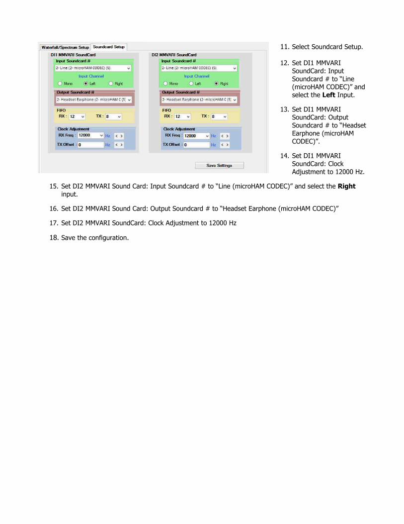
11. Select Soundcard Setup.
12. Set DI1 MMVARI
SoundCard: Input
Soundcard # to “Line (microHAM CODEC)” and
select the Left Input.
13. Set DI1 MMVARI SoundCard: Output
Soundcard # to “Headset
Earphone (microHAM
CODEC)”.
14. Set DI1 MMVARI
SoundCard: Clock
Adjustment to 12000 Hz.
15. Set DI2 MMVARI Sound Card: Input Soundcard # to “Line (microHAM CODEC)” and select the Right
input.
16. Set DI2 MMVARI Sound Card: Output Soundcard # to “Headset Earphone (microHAM CODEC)”
17. Set DI2 MMVARI SoundCard: Clock Adjustment to 12000 Hz
18. Save the configuration.