mitsubishi cnc ethernet/ip configuration tool … · this instruction manual describes how to use...
TRANSCRIPT
Introduction
This instruction manual describes how to use MITSUBISHI CNC EtherNet/IP Configuration Tool. Incorrect
handling may lead to unforeseen accidents, so make sure to read this instruction manual thoroughly before
operation to ensure correct usage.
MITSUBISHI CNC EtherNet/IP Configuration Tool supports the following NC series.
Appropriate NC
M800W/M800S/M80/M80W/E80 Series
Notes on Reading This Manual
(1) For the specifications of individual machine tools, refer to the manuals issued by the respective machine tool builders. The "restrictions" and "available functions" described by the machine tool builders have precedence over this manual.
(2) This manual describes as many special operations as possible, but it should be kept in mind that operations not mentioned in this manual cannot be performed.

Precautions for Safety
Always read the specifications issued by the machine tool builder, this manual, related manuals and attached
documents before installation, operation, programming, maintenance or inspection to ensure correct use.
Understand this numerical controller, safety items and cautions before using the unit.
This manual ranks the safety precautions into "DANGER", "WARNING" and "CAUTION".
DANGER When the user may be subject to imminent fatalities or major injuries if handling is mistaken.
WARNING When the user may be subject to fatalities or major injuries if handling is mistaken.
CAUTION When the user may be subject to injuries or when property damage may occur if handling is mistaken.
Note that even items ranked as " CAUTION", may lead to major results depending on the situation. In any case, important information that must always be observed is described.
DANGER
Not applicable in this manual.
WARNING
Not applicable in this manual.
CAUTION
1. Items related to product and manual
If the descriptions relating to the "restrictions" and "allowable conditions" conflict between this manual and the machine tool builder's instruction manual‚ the latter has priority over the former.
The operations to which no reference is made in this manual should be considered impossible. This manual is compiled on the assumption that your machine is provided with all optional functions.
Confirm the functions available for your machine before proceeding to operation by referring to the specification issued by the machine tool builder.
In some NC system versions‚ there may be cases that different pictures appear on the screen‚ the machine operates in a different way on some function is not activated.
Check condition of the NC device to transfer NC data and machining program by MITSUBISHI CNC EtherNet/IP Configuration Tool to NC device connected to the network. It may cause unintended rewriting of the program.


Trademarks MELDAS, MELSEC, EZSocket, EZMotion, iQ Platform, MELSOFT, GOT, CC-Link, CC-Link/LT and CC-Link
IE are either trademarks or registered trademarks of Mitsubishi Electric Corporation in Japan and/or other
countries.
Ethernet is a registered trademark of Xerox Corporation in the United States and/or other countries.
Microsoft® and Windows® are either trademarks or registered trademarks of Microsoft Corporation in the
United States and/or other countries.
EtherNet/IP is a trademark of Open DeviceNet Vendor Association,Inc.
Other company and product names that appear in this manual are trademarks or registered trademarks of the
respective companies.

Contents
1. Outline .................................................................................................................................................................................. 1 2. Operating Environment of the EIP-CT .................................................................................................................................. 1 3. Installation ............................................................................................................................................................................ 2
3.1 Requirements ............................................................................................................................................................. 2 3.2 Installation Procedure ................................................................................................................................................. 2
3.2.1 Start setup.exe ................................................................................................................................................ 3 3.2.2 Install Runtime ................................................................................................................................................ 3 3.2.3 Start the EIP-CT Installation ........................................................................................................................... 5 3.2.4 Specify the Destination Folder for Installation ................................................................................................. 5 3.2.5 Start Installation .............................................................................................................................................. 6 3.2.6 Copying ........................................................................................................................................................... 7 3.2.7 Installation Completed .................................................................................................................................... 7 3.2.8 Start the EIP-CT ............................................................................................................................................. 8
3.3 Uninstallation .............................................................................................................................................................. 9 4. Screen Overview ................................................................................................................................................................ 10
4.1 Screen Configuration ................................................................................................................................................ 10 4.2 Display Items ............................................................................................................................................................ 10
5. Device Setting and Configuration File Output ..................................................................................................................... 11 5.1 When NC is Used with a Scanner ............................................................................................................................ 11
5.1.1 Configuration ................................................................................................................................................ 11 5.1.2 Operations in the EIP-CT .............................................................................................................................. 12
5.2 Adapter Function ...................................................................................................................................................... 24 5.2.1 Configuration ................................................................................................................................................ 24 5.2.2 How to Obtain the EDS File .......................................................................................................................... 24 5.2.3 Configuration Setting .................................................................................................................................... 25
6. Diagnostic Function ............................................................................................................................................................ 28 6.1 Procedures for Diagnostic Startup............................................................................................................................ 28 6.2 Diagnostic Screen .................................................................................................................................................... 30
6.2.1 Diagnostic Status Confirmation Screen ........................................................................................................ 30 6.2.2 I/O Data Confirmation Screen ....................................................................................................................... 31
7. Compatible NC Versions .................................................................................................................................................... 32

MITSUBISHI CNC EtherNet/IP Configuration Tool Instruction Manual
1. Outline
1 IB-1501536-A
1. Outline
In order to use the NC EtherNet/IP function, the connected device needs to be set with the
"EtherNet/IP Configuration Tool (hereafter EIP-CT)". The EIP-CT is a tool which operates on Windows.
With the EIP-CT, in addition to the setting of connected devices, diagnostic function to confirm the
connecting status of connected devices is available.
This manual describes the essential information for the EIP-CT only. For details about the EIP-CT,
refer to Help of the EIP-CT*.
*The contents that can be set with the EIP-CT depends on the NC EtherNet/IP specifications.
Also, the following functions in Help cannot be used with NC. ∙ The contents in "Downloading the configuration"
∙ The following contents in "8. Properties of the EtherNet/IP scanner"
- The Ethernet tab
- The EtherNet/IP tab
- The User Data tab ∙ The contents in "13. Device names and items configuration"
∙ QoS, DNS Server, Host Name, Domain Name, DHCP, and BOOTP settings
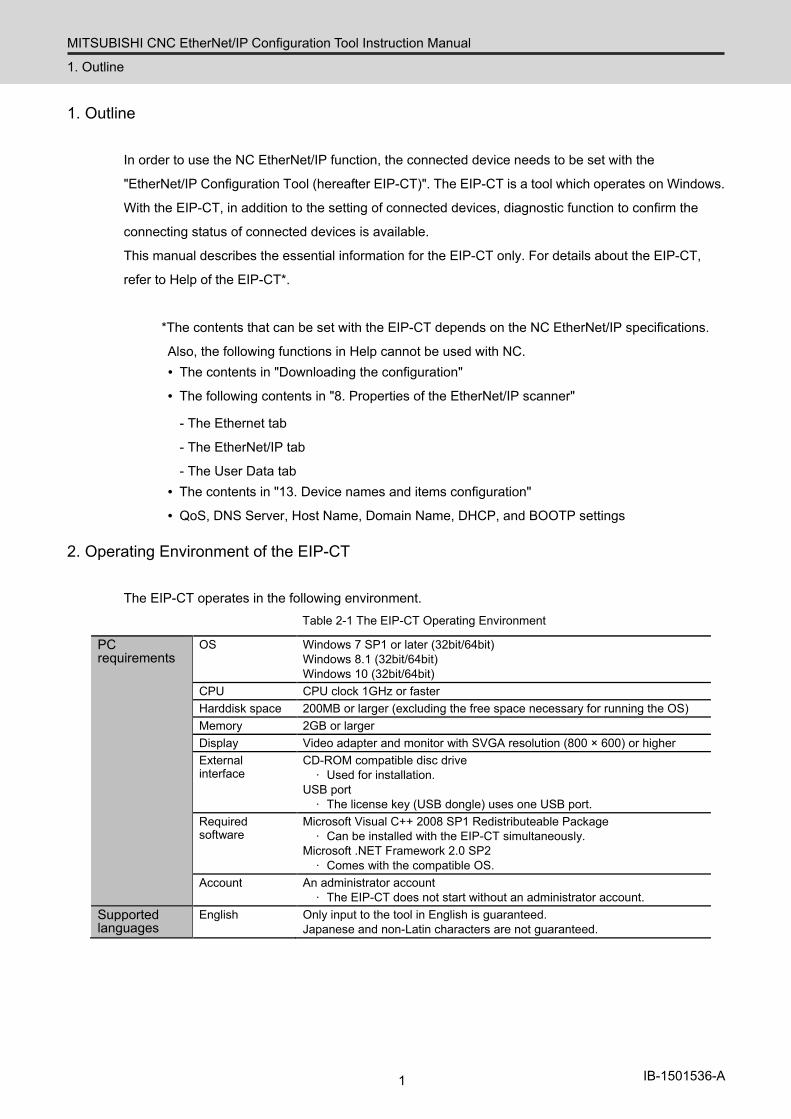
2. Operating Environment of the EIP-CT
The EIP-CT operates in the following environment. Table 2-1 The EIP-CT Operating Environment
PC requirements
OS Windows 7 SP1 or later (32bit/64bit) Windows 8.1 (32bit/64bit) Windows 10 (32bit/64bit)
CPU CPU clock 1GHz or faster Harddisk space 200MB or larger (excluding the free space necessary for running the OS) Memory 2GB or larger Display Video adapter and monitor with SVGA resolution (800 × 600) or higher External interface
CD-ROM compatible disc drive ∙ Used for installation.
USB port ∙ The license key (USB dongle) uses one USB port.
Required software
Microsoft Visual C++ 2008 SP1 Redistributeable Package ∙ Can be installed with the EIP-CT simultaneously.
Microsoft .NET Framework 2.0 SP2 ∙ Comes with the compatible OS.
Account An administrator account ∙ The EIP-CT does not start without an administrator account.
Supported languages
English Only input to the tool in English is guaranteed. Japanese and non-Latin characters are not guaranteed.
MITSUBISHI CNC EtherNet/IP Configuration Tool Instruction Manual
3. Installation
2 IB-1501536-A
3. Installation
The following describes how to install the EIP-CT.
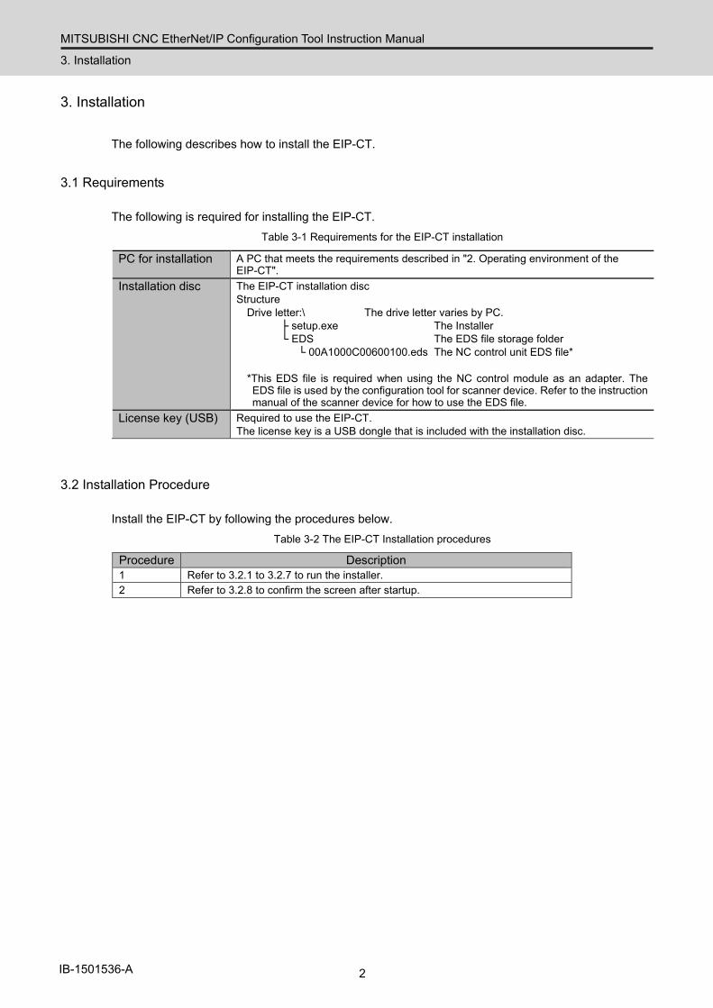
3.1 Requirements
The following is required for installing the EIP-CT. Table 3-1 Requirements for the EIP-CT installation
PC for installation A PC that meets the requirements described in "2. Operating environment of the EIP-CT".
Installation disc The EIP-CT installation disc Structure
Drive letter:\ The drive letter varies by PC. ├ setup.exe The Installer └ EDS The EDS file storage folder
└ 00A1000C00600100.eds The NC control unit EDS file*
*This EDS file is required when using the NC control module as an adapter. The EDS file is used by the configuration tool for scanner device. Refer to the instruction manual of the scanner device for how to use the EDS file.
License key (USB) Required to use the EIP-CT. The license key is a USB dongle that is included with the installation disc.
3.2 Installation Procedure
Install the EIP-CT by following the procedures below. Table 3-2 The EIP-CT Installation procedures
Procedure Description 1 Refer to 3.2.1 to 3.2.7 to run the installer. 2 Refer to 3.2.8 to confirm the screen after startup.
MITSUBISHI CNC EtherNet/IP Configuration Tool Instruction Manual
3. Installation
3 IB-1501536-A
3.2.1 Start setup.exe
Execute "Drive letter\:setup.exe" from the installation disc.
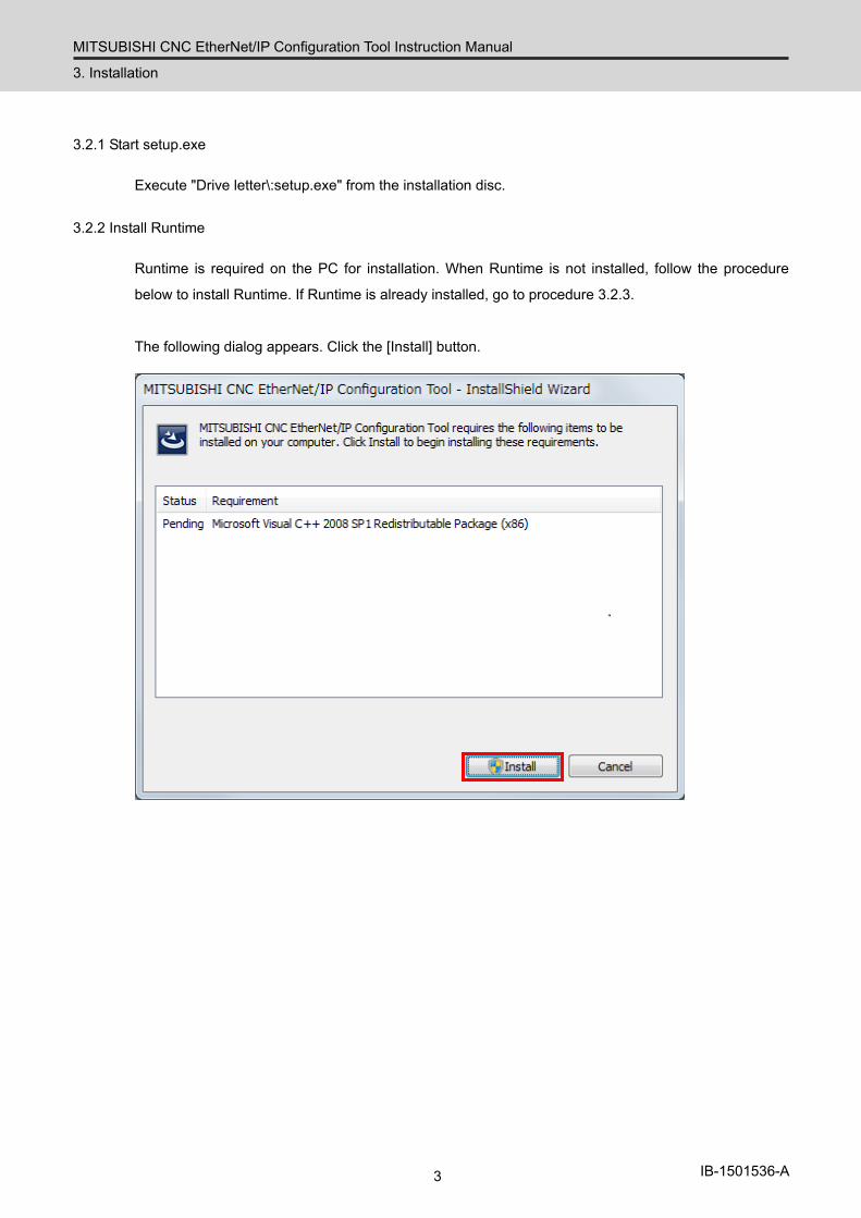
3.2.2 Install Runtime
Runtime is required on the PC for installation. When Runtime is not installed, follow the procedure
below to install Runtime. If Runtime is already installed, go to procedure 3.2.3.
The following dialog appears. Click the [Install] button.

MITSUBISHI CNC EtherNet/IP Configuration Tool Instruction Manual
3. Installation
4 IB-1501536-A
When the user account control function asks for permission to make changes to the computer, click the
[Yes] button.
Wait until copying is completed.
MITSUBISHI CNC EtherNet/IP Configuration Tool Instruction Manual
3. Installation
5 IB-1501536-A
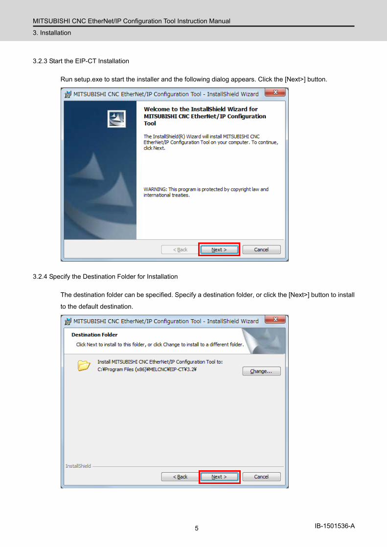
3.2.3 Start the EIP-CT Installation
Run setup.exe to start the installer and the following dialog appears. Click the [Next>] button.
3.2.4 Specify the Destination Folder for Installation
The destination folder can be specified. Specify a destination folder, or click the [Next>] button to install
to the default destination.
MITSUBISHI CNC EtherNet/IP Configuration Tool Instruction Manual
3. Installation
6 IB-1501536-A
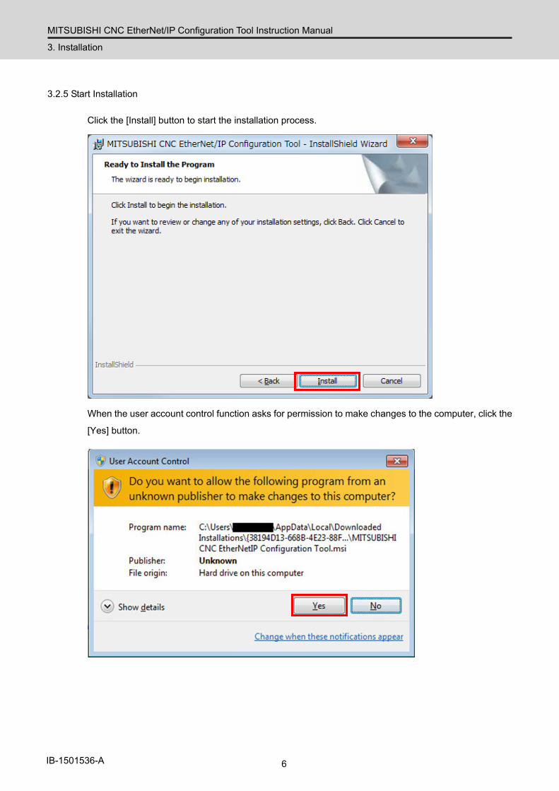
3.2.5 Start Installation
Click the [Install] button to start the installation process.
When the user account control function asks for permission to make changes to the computer, click the
[Yes] button.
MITSUBISHI CNC EtherNet/IP Configuration Tool Instruction Manual
3. Installation
7 IB-1501536-A
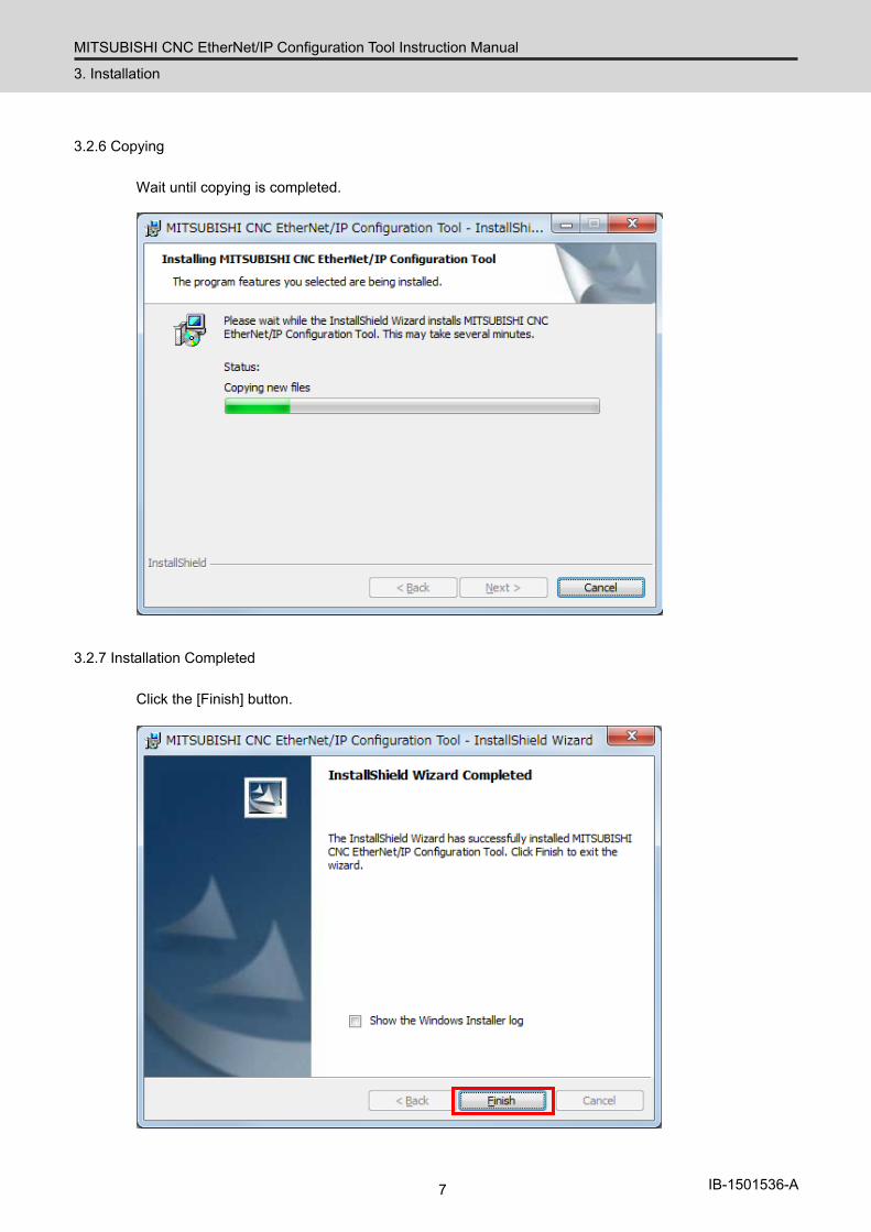
3.2.6 Copying
Wait until copying is completed.
3.2.7 Installation Completed
Click the [Finish] button.

MITSUBISHI CNC EtherNet/IP Configuration Tool Instruction Manual
3. Installation
8 IB-1501536-A
3.2.8 Start the EIP-CT
Insert the license key to the PC with the EIP-CT installed, and follow the procedure below to start the EIP-CT.
*Be sure to insert the license key before starting the EIP-CT.
*The driver for the license key is automatically installed when the license key is inserted into the PC.
[Start] – [All programs] – [MELCNC] – [EIP Configuration tool] – [EIP-CT]
Start the EIP-CT, and confirm that the following screen appears. If the following screen does not
appear, the installation may have failed. Install the EIP-CT again from the beginning.
This is the end of the EIP-CT installation procedure.
MITSUBISHI CNC EtherNet/IP Configuration Tool Instruction Manual
3. Installation
9 IB-1501536-A
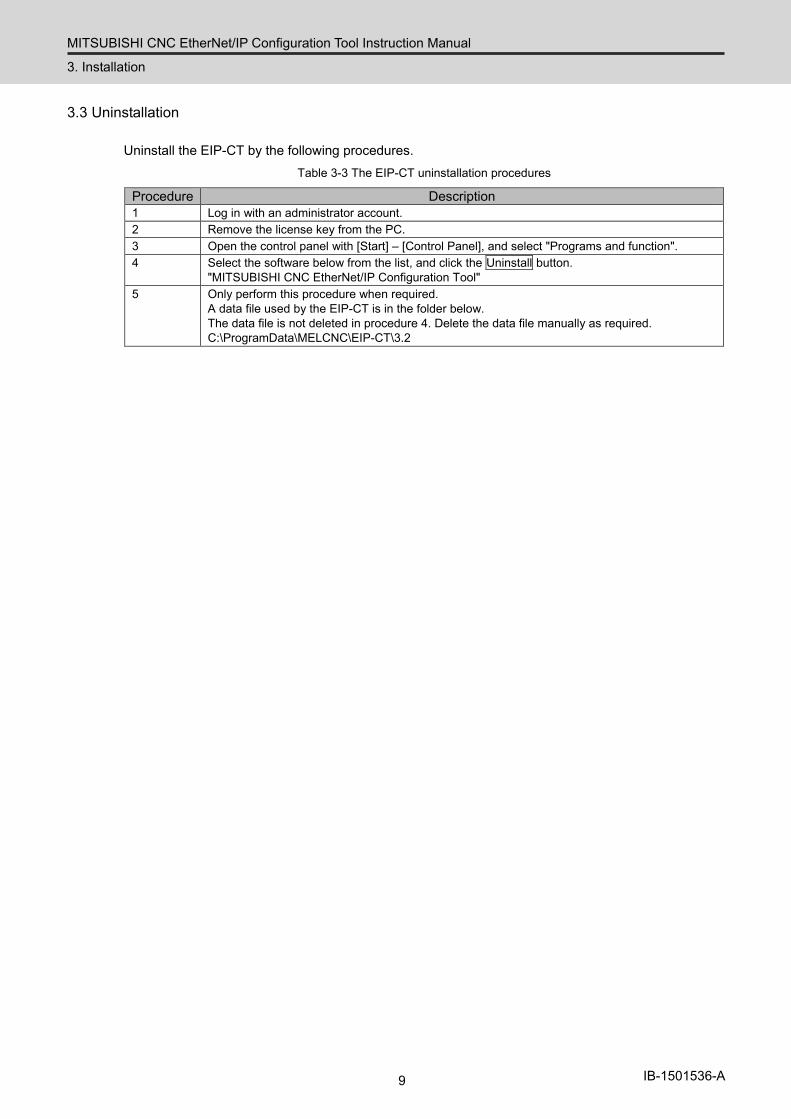
3.3 Uninstallation
Uninstall the EIP-CT by the following procedures. Table 3-3 The EIP-CT uninstallation procedures
Procedure Description 1 Log in with an administrator account. 2 Remove the license key from the PC. 3 Open the control panel with [Start] – [Control Panel], and select "Programs and function". 4 Select the software below from the list, and click the Uninstall button.
"MITSUBISHI CNC EtherNet/IP Configuration Tool" 5 Only perform this procedure when required.
A data file used by the EIP-CT is in the folder below. The data file is not deleted in procedure 4. Delete the data file manually as required. C:\ProgramData\MELCNC\EIP-CT\3.2
MITSUBISHI CNC EtherNet/IP Configuration Tool Instruction Manual
4. Screen Overview
10 IB-1501536-A
4. Screen Overview
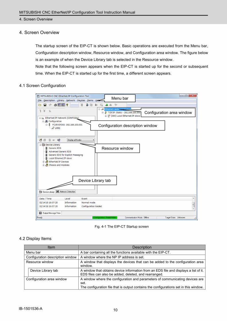
The startup screen of the EIP-CT is shown below. Basic operations are executed from the Menu bar,
Configuration description window, Resource window, and Configuration area window. The figure below
is an example of when the Device Library tab is selected in the Resource window.
Note that the following screen appears when the EIP-CT is started up for the second or subsequent
time. When the EIP-CT is started up for the first time, a different screen appears.
4.1 Screen Configuration
Menu bar
Configuration description window
Device Library tab
Configuration area window
Resource window
Fig. 4-1 The EIP-CT Startup screen
4.2 Display Items
Item Description Menu bar A bar containing all the functions available with the EIP-CT. Configuration description window A window where the NP IP address is set. Resource window A window that displays the devices that can be added to the configuration area
window. Device Library tab A window that obtains device information from an EDS file and displays a list of it.
EDS files can also be added, deleted, and rearranged. Configuration area window A window where the configuration and parameters of communicating devices are
set. The configuration file that is output contains the configurations set in this window.
MITSUBISHI CNC EtherNet/IP Configuration Tool Instruction Manual
5. Device Setting and Configuration File Output
11 IB-1501536-A
5. Device Setting and Configuration File Output
This section describes the basic operations for setting devices, and generating configuration files.
The setting method for devices depends on whether an NC control unit is used with a scanner or with
an adapter. A description for each case follows.
5.1 When NC is Used with a Scanner
With the EtherNet/IP scanner function, the NC control unit can communicate with adapters (such as I/O
units).
The scanner function and the adapter function can be used at the same time.
The following describes the operations on the EIP-CT when using the NC control unit with a scanner.
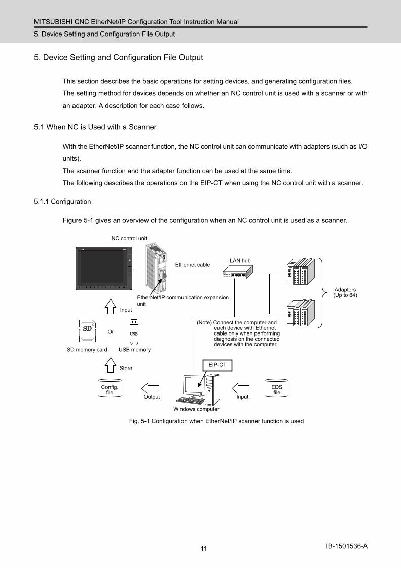
5.1.1 Configuration
Figure 5-1 gives an overview of the configuration when an NC control unit is used as a scanner.
EtherNet/IP communication expansion unit
NC control unit
Ethernet cable
LAN hub
Windows computer
Adapters (Up to 64)
EIP-CT
SD
USB
Or
SD memory card USB memory
EDS file
Config. file
(Note) Connect the computer and each device with Ethernet cable only when performing diagnosis on the connected devices with the computer.
Input Output
Store
Input
Fig. 5-1 Configuration when EtherNet/IP scanner function is used
MITSUBISHI CNC EtherNet/IP Configuration Tool Instruction Manual
5. Device Setting and Configuration File Output
12 IB-1501536-A
5.1.2 Operations in the EIP-CT
In order to use EtherNet/IP, the connected device needs to be set using the EIP-CT tool on a Windows
computer. The configuration file output from the EIP-CT is input to the NC control unit using the NC
control unit input/output function.
Output the configuration file by following the procedure below.
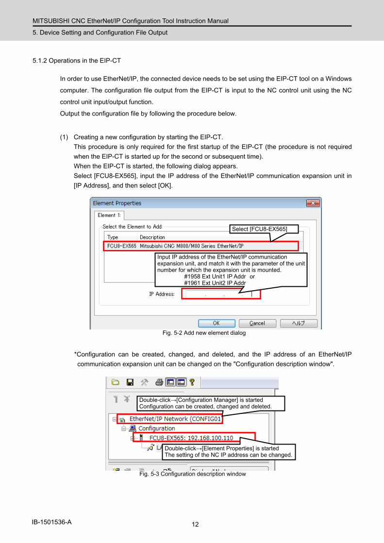
(1) Creating a new configuration by starting the EIP-CT. This procedure is only required for the first startup of the EIP-CT (the procedure is not required
when the EIP-CT is started up for the second or subsequent time). When the EIP-CT is started, the following dialog appears. Select [FCU8-EX565], input the IP address of the EtherNet/IP communication expansion unit in [IP Address], and then select [OK].
Select [FCU8-EX565]
Input IP address of the EtherNet/IP communication expansion unit, and match it with the parameter of the unit number for which the expansion unit is mounted.
#1958 Ext Unit1 IP Addr or #1961 Ext Unit2 IP Addr
Fig. 5-2 Add new element dialog
*Configuration can be created, changed, and deleted, and the IP address of an EtherNet/IP communication expansion unit can be changed on the "Configuration description window".
Double-click→[Configuration Manager] is started Configuration can be created, changed and deleted.
Double-click→[Element Properties] is started The setting of the NC IP address can be changed.
Fig. 5-3 Configuration description window
MITSUBISHI CNC EtherNet/IP Configuration Tool Instruction Manual
5. Device Setting and Configuration File Output
13 IB-1501536-A
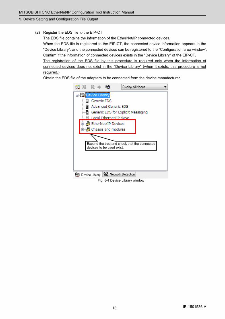
(2) Register the EDS file to the EIP-CT The EDS file contains the information of the EtherNet/IP connected devices.
When the EDS file is registered to the EIP-CT, the connected device information appears in the "Device Library", and the connected devices can be registered to the "Configuration area window". Confirm if the information of connected devices exists in the "Device Library" of the EIP-CT. The registration of the EDS file by this procedure is required only when the information of connected devices does not exist in the "Device Library" (when it exists, this procedure is not required.) Obtain the EDS file of the adapters to be connected from the device manufacturer.
Expand the tree and check that the connected devices to be used exist.
Fig. 5-4 Device Library window
MITSUBISHI CNC EtherNet/IP Configuration Tool Instruction Manual
5. Device Setting and Configuration File Output
14 IB-1501536-A
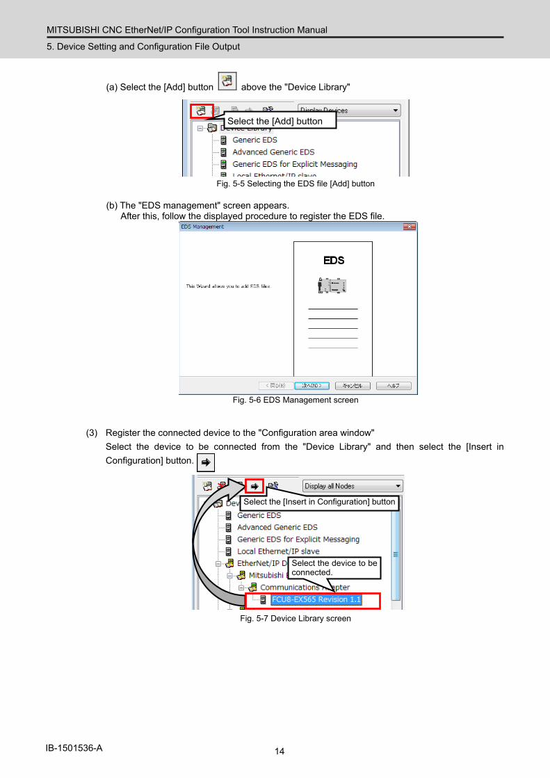
(a) Select the [Add] button above the "Device Library"
Select the [Add] button
Fig. 5-5 Selecting the EDS file [Add] button
(b) The "EDS management" screen appears.
After this, follow the displayed procedure to register the EDS file.
Fig. 5-6 EDS Management screen
(3) Register the connected device to the "Configuration area window" Select the device to be connected from the "Device Library" and then select the [Insert in Configuration] button.
Select the device to be connected.
Select the [Insert in Configuration] button
Fig. 5-7 Device Library screen
MITSUBISHI CNC EtherNet/IP Configuration Tool Instruction Manual
5. Device Setting and Configuration File Output
15 IB-1501536-A
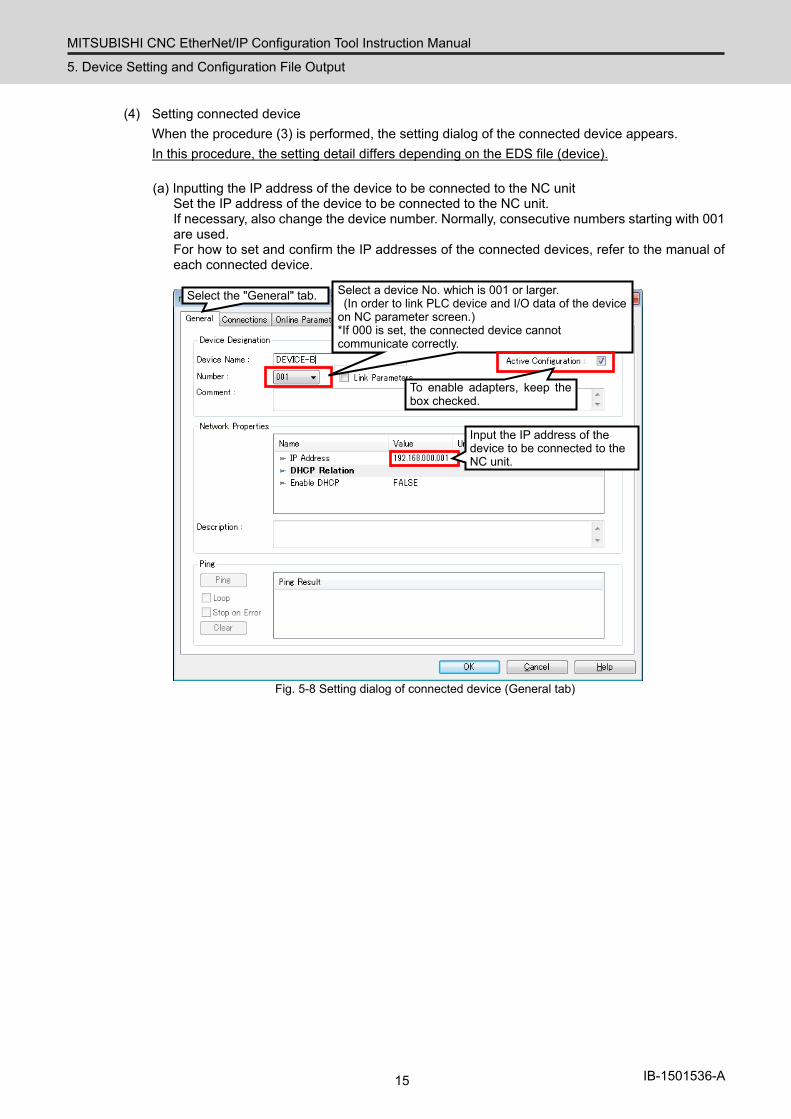
(4) Setting connected device When the procedure (3) is performed, the setting dialog of the connected device appears. In this procedure, the setting detail differs depending on the EDS file (device).
(a) Inputting the IP address of the device to be connected to the NC unit
Set the IP address of the device to be connected to the NC unit. If necessary, also change the device number. Normally, consecutive numbers starting with 001 are used. For how to set and confirm the IP addresses of the connected devices, refer to the manual of each connected device.
Select a device No. which is 001 or larger. (In order to link PLC device and I/O data of the device on NC parameter screen.) *If 000 is set, the connected device cannot communicate correctly.
Input the IP address of the device to be connected to the NC unit.
Select the "General" tab.
To enable adapters, keep the box checked.
Fig. 5-8 Setting dialog of connected device (General tab)
MITSUBISHI CNC EtherNet/IP Configuration Tool Instruction Manual
5. Device Setting and Configuration File Output
16 IB-1501536-A
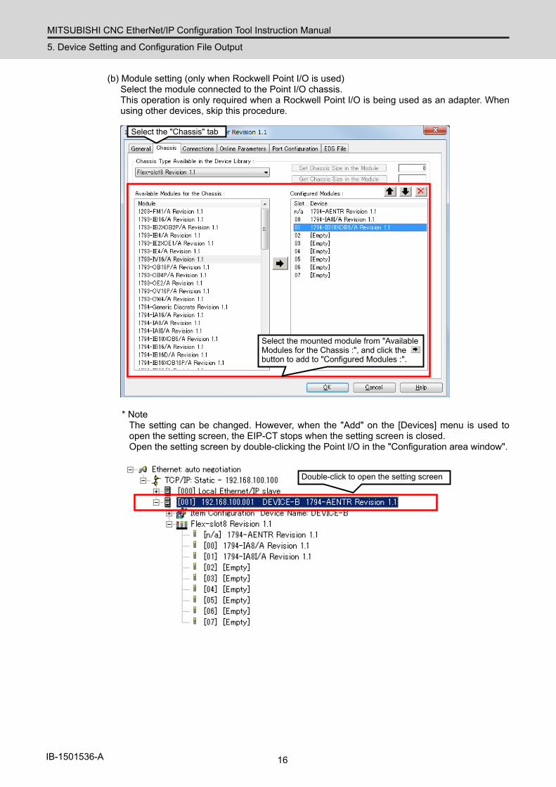
(b) Module setting (only when Rockwell Point I/O is used) Select the module connected to the Point I/O chassis. This operation is only required when a Rockwell Point I/O is being used as an adapter. When using other devices, skip this procedure.
Select the "Chassis" tab
Select the mounted module from "Available Modules for the Chassis :", and click the button to add to "Configured Modules :".
* Note
The setting can be changed. However, when the "Add" on the [Devices] menu is used to open the setting screen, the EIP-CT stops when the setting screen is closed. Open the setting screen by double-clicking the Point I/O in the "Configuration area window".
Double-click to open the setting screen
MITSUBISHI CNC EtherNet/IP Configuration Tool Instruction Manual
5. Device Setting and Configuration File Output
17 IB-1501536-A
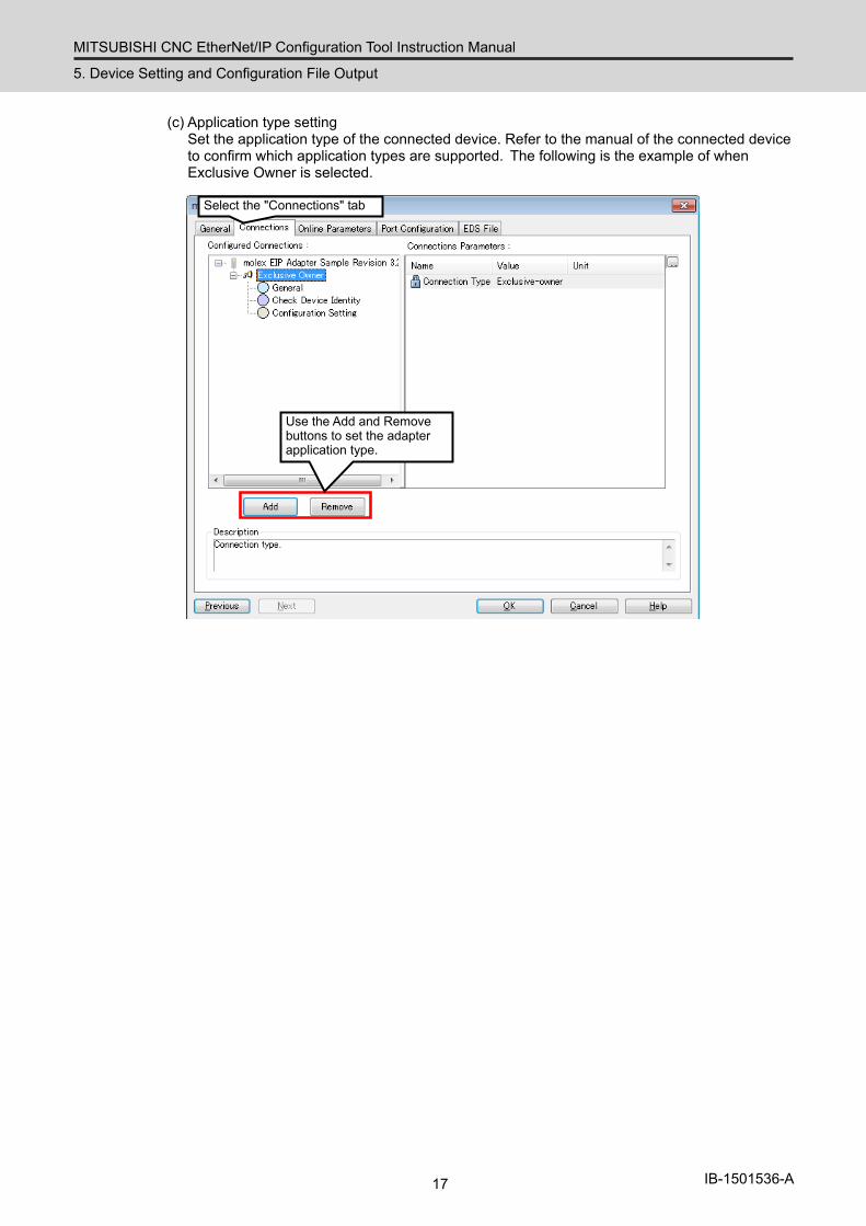
(c) Application type setting Set the application type of the connected device. Refer to the manual of the connected device to confirm which application types are supported. The following is the example of when Exclusive Owner is selected.
Select the "Connections" tab
Use the Add and Remove buttons to set the adapter application type.
MITSUBISHI CNC EtherNet/IP Configuration Tool Instruction Manual
5. Device Setting and Configuration File Output
18 IB-1501536-A
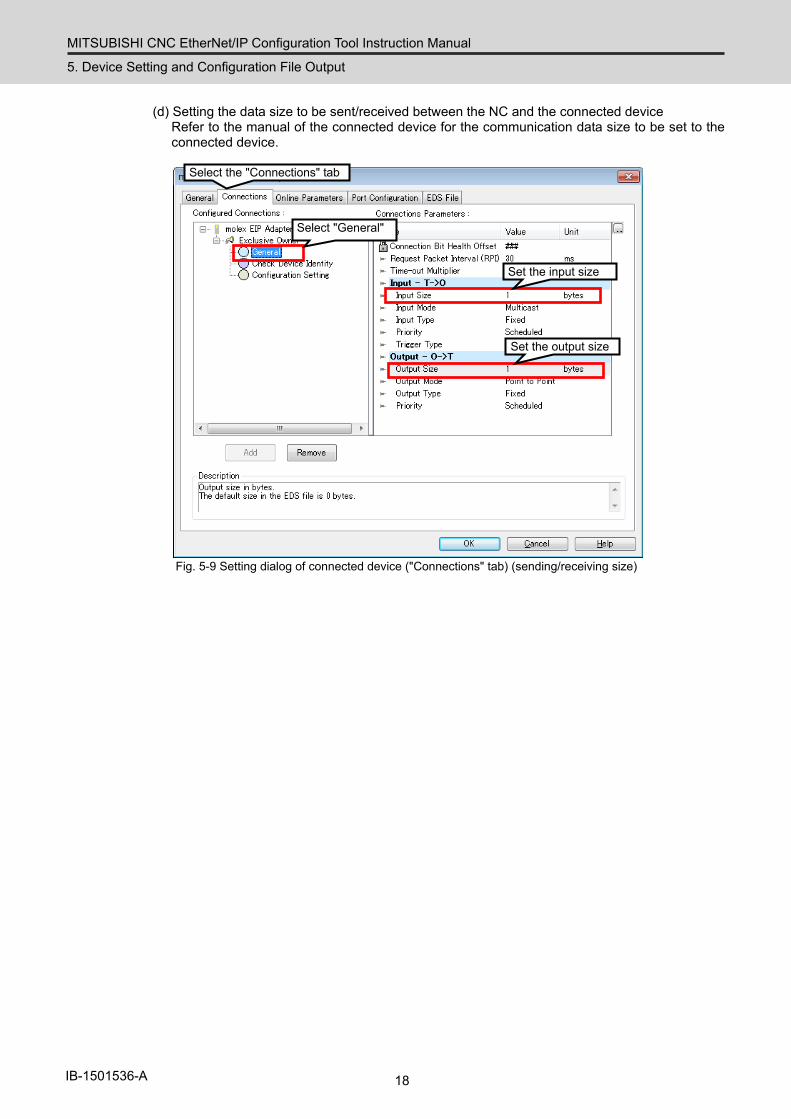
(d) Setting the data size to be sent/received between the NC and the connected device Refer to the manual of the connected device for the communication data size to be set to the connected device.
Select "General"
Set the input size
Select the "Connections" tab
Set the output size
Fig. 5-9 Setting dialog of connected device ("Connections" tab) (sending/receiving size)
MITSUBISHI CNC EtherNet/IP Configuration Tool Instruction Manual
5. Device Setting and Configuration File Output
19 IB-1501536-A
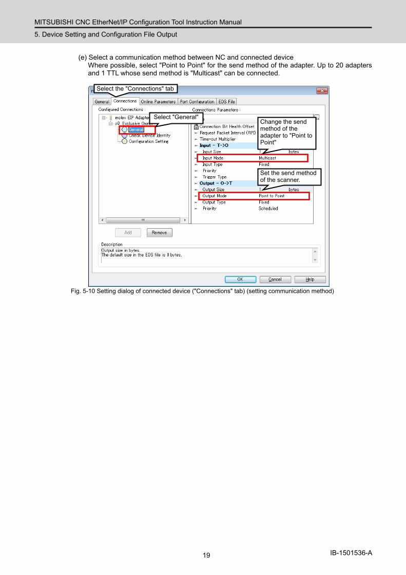
(e) Select a communication method between NC and connected device Where possible, select "Point to Point" for the send method of the adapter. Up to 20 adapters and 1 TTL whose send method is "Multicast" can be connected.
Select "General" Change the send method of the adapter to "Point to Point"
Select the "Connections" tab
Set the send method of the scanner.
Fig. 5-10 Setting dialog of connected device ("Connections" tab) (setting communication method)

MITSUBISHI CNC EtherNet/IP Configuration Tool Instruction Manual
5. Device Setting and Configuration File Output
20 IB-1501536-A
(f) Setting instance ID input/output object This setting may be unnecessary. Refer to the manual of the connected device for the instance ID to be set.
Select "Configuration Setting"
Input instance ID of "Assembly" object. *Setting is not required when nothing is displayed.
Select the "Connections" tab
Fig. 5-11 Setting dialog of connected device ("Connections" tab)
MITSUBISHI CNC EtherNet/IP Configuration Tool Instruction Manual
5. Device Setting and Configuration File Output
21 IB-1501536-A
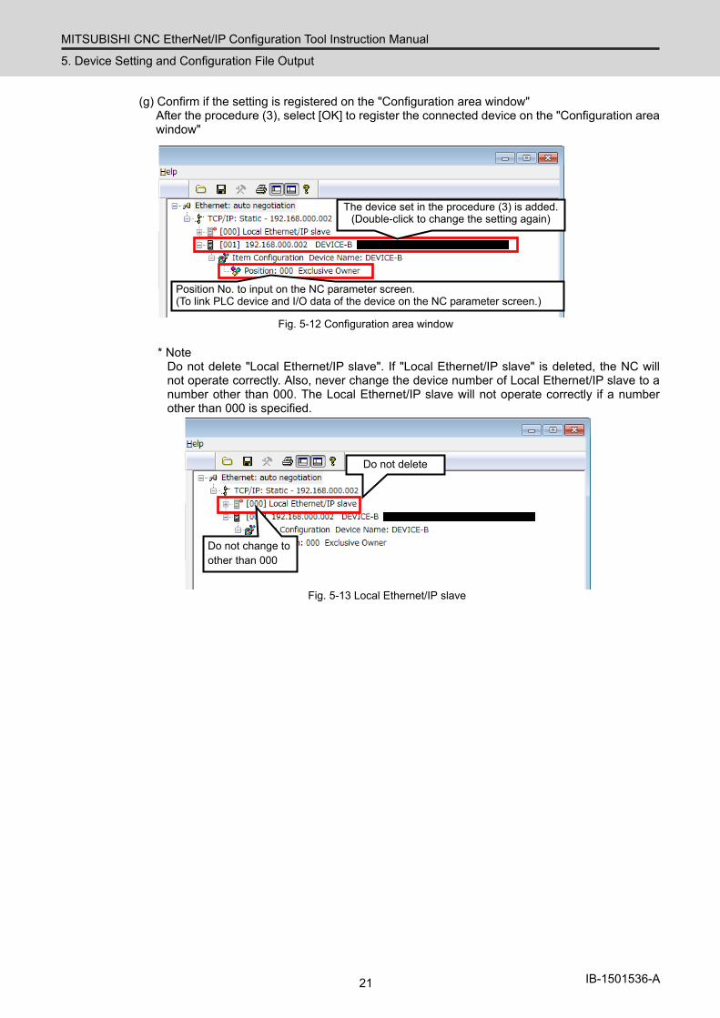
(g) Confirm if the setting is registered on the "Configuration area window" After the procedure (3), select [OK] to register the connected device on the "Configuration area window"
The device set in the procedure (3) is added. (Double-click to change the setting again)
Position No. to input on the NC parameter screen. (To link PLC device and I/O data of the device on the NC parameter screen.)
Fig. 5-12 Configuration area window
* Note Do not delete "Local Ethernet/IP slave". If "Local Ethernet/IP slave" is deleted, the NC will not operate correctly. Also, never change the device number of Local Ethernet/IP slave to a number other than 000. The Local Ethernet/IP slave will not operate correctly if a number other than 000 is specified.
Do not delete
Do not change to other than 000
Fig. 5-13 Local Ethernet/IP slave
MITSUBISHI CNC EtherNet/IP Configuration Tool Instruction Manual
5. Device Setting and Configuration File Output
22 IB-1501536-A
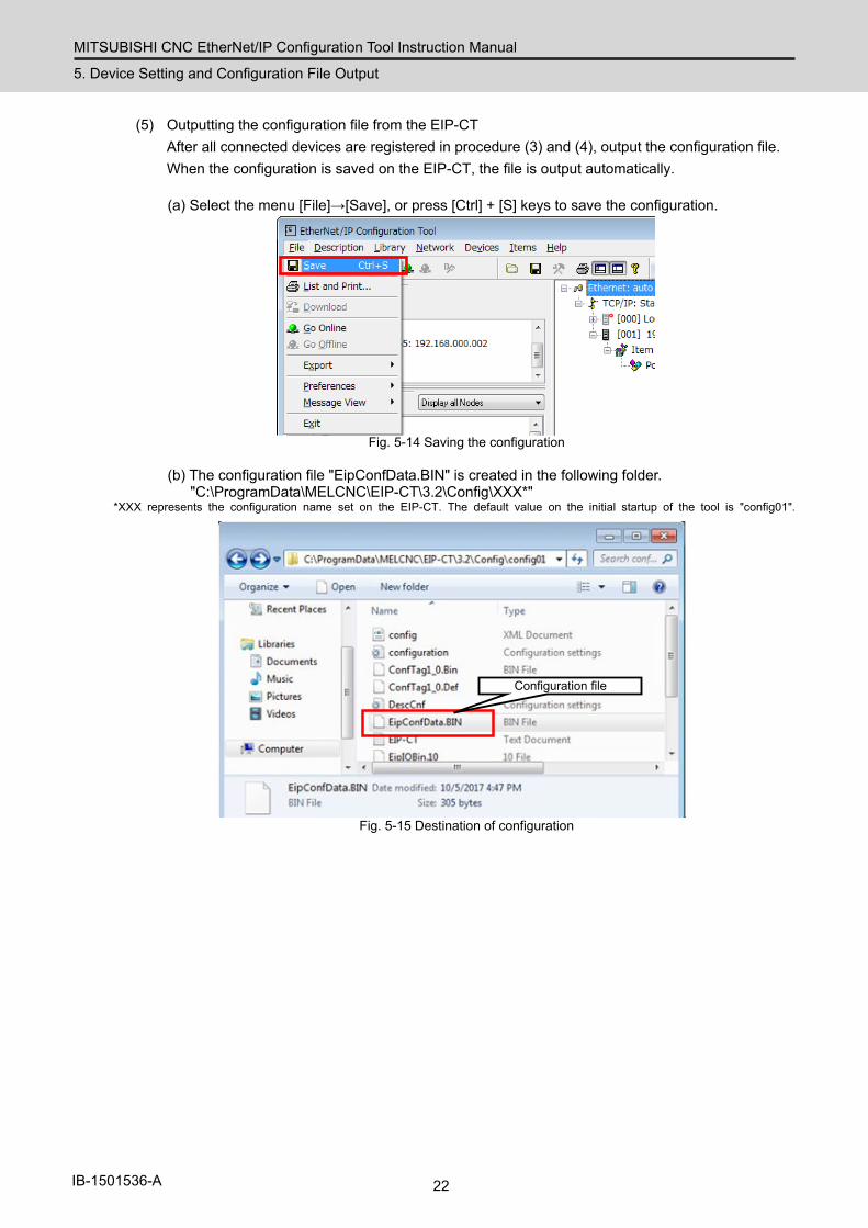
(5) Outputting the configuration file from the EIP-CT After all connected devices are registered in procedure (3) and (4), output the configuration file. When the configuration is saved on the EIP-CT, the file is output automatically.
(a) Select the menu [File]→[Save], or press [Ctrl] + [S] keys to save the configuration.
Fig. 5-14 Saving the configuration
(b) The configuration file "EipConfData.BIN" is created in the following folder. "C:\ProgramData\MELCNC\EIP-CT\3.2\Config\XXX*"
*XXX represents the configuration name set on the EIP-CT. The default value on the initial startup of the tool is "config01".
Configuration file
Fig. 5-15 Destination of configuration

MITSUBISHI CNC EtherNet/IP Configuration Tool Instruction Manual
5. Device Setting and Configuration File Output
23 IB-1501536-A
(6) Inputting the configuration file to the NC control unit This section explains how to input the configuration file "EipConfData.BIN" to the NC control unit. This operation uses the "input/output" function of NC.
[Preparation] Save the configuration file "EipConfData.BIN" on an SD card or a USB memory and insert it in the NC control unit.
After inserting the SD card or USB memory, perform the following operations on the input/output screen.
(a) Select [Mainte]→[I/O] to move to the input/output screen. (b) For [A:Dev], select the device where the configuration file is saved. (c) For the file name for [A:Dev], set "EipConfData.BIN". (d) For [B:Dev], select "Memory". (e) For the directory of [B:Dev], input "/FNET".
"FieldNet Config File" is set to the directory automatically. (f) Select [Trnfr A→B].
The configuration file is input to the NC control unit.
Fig. 5-16 Inputting the configuration file
Note 1) If the configuration file name is changed from "EipConfData.BIN" with the "Rename" function on the input/output screen, the NC control unit does not recognize the renamed file as the EtherNet/IP configuration file.
MITSUBISHI CNC EtherNet/IP Configuration Tool Instruction Manual
5. Device Setting and Configuration File Output
24 IB-1501536-A
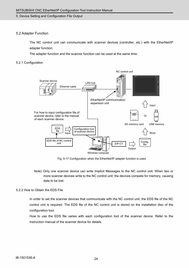
5.2 Adapter Function
The NC control unit can communicate with scanner devices (controller, etc.) with the EtherNet/IP
adapter function.
The adapter function and the scanner function can be used at the same time.
5.2.1 Configuration
Scanner device
EtherNet/IP communication expansion unit
NC control unit
Ethernet cable LAN hub
Windows computer
Configuration tool of scanner device
EDS file
Output
EDS file of NC control unit
For how to input configuration file of scanner device, refer to the manual of each scanner device.
EIP-CT
SD
USB
Or
SD memory card USB memory
Config. file
Store
Input
Input
Fig. 5-17 Configuration when the EtherNet/IP adapter function is used
Note) Only one scanner device can write Implicit Messages to the NC control unit. When two or more scanner devices write to the NC control unit, the devices compete for memory, causing data to be lost.
5.2.2 How to Obtain the EDS File
In order to set the scanner devices that communicate with the NC control unit, the EDS file of the NC
control unit is required. The EDS file of the NC control unit is stored on the installation disc of the
configuration tool.
How to use the EDS file varies with each configuration tool of the scanner device. Refer to the
instruction manual of the scanner device for details.
MITSUBISHI CNC EtherNet/IP Configuration Tool Instruction Manual
5. Device Setting and Configuration File Output
25 IB-1501536-A
5.2.3 Configuration Setting
In order to use the adapter function, the connected device needs to be set with the EIP-CT, which is
the tool operated on Windows. The configuration file with the adapter function enabled is output from
the EIP-CT. Use the input/output function of the NC control unit to input the configuration file to the NC
control unit, enabling the use of the NC control unit adapter function.
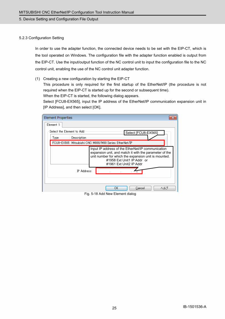
(1) Creating a new configuration by starting the EIP-CT This procedure is only required for the first startup of the EtherNet/IP (the procedure is not required when the EIP-CT is started up for the second or subsequent time). When the EIP-CT is started, the following dialog appears. Select [FCU8-EX565], input the IP address of the EtherNet/IP communication expansion unit in [IP Address], and then select [OK].
Select [FCU8-EX565]
Input IP address of the EtherNet/IP communication expansion unit, and match it with the parameter of the unit number for which the expansion unit is mounted.
#1958 Ext Unit1 IP Addr or #1961 Ext Unit2 IP Addr
Fig. 5-18 Add New Element dialog

MITSUBISHI CNC EtherNet/IP Configuration Tool Instruction Manual
5. Device Setting and Configuration File Output
26 IB-1501536-A
(2) Setting the adapter function Set the adapter function. (a) Double-click "Local Ethernet/IP slave" in the "Configuration area window" to open the "Local
Ethernet/IP slave" dialog.
Double-click→[Local Ethernet/IP slave dialog] is started
Fig. 5-19 Configuration area window
(b) Set the adapter function Enable the adapter function. Set the sizes of instance 101 (PLC output data) and instance 102 (PLC input data) of assembly objects. After setting the following, select [OK].
Check this box to set to Active.
Set the size of IN/OUT Note that it is opposite to the size of IN/OUT set with the scanner device.
Use "000" for device No.
Specify within the range of 1 to 500.
Check this box when enabling the Input Only or Listen Only function.
Do not change the initial values.
Fig. 5-20 Setting dialog of the NC control unit (Host)
MITSUBISHI CNC EtherNet/IP Configuration Tool Instruction Manual
5. Device Setting and Configuration File Output
27 IB-1501536-A
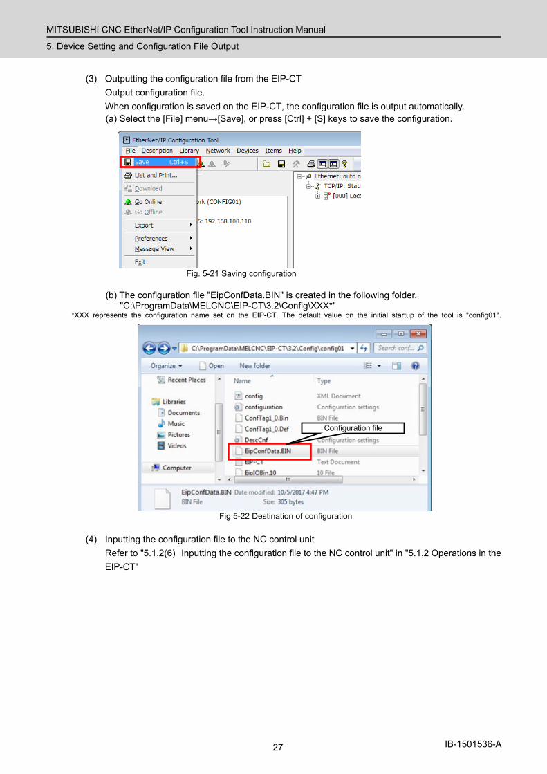
(3) Outputting the configuration file from the EIP-CT Output configuration file. When configuration is saved on the EIP-CT, the configuration file is output automatically. (a) Select the [File] menu→[Save], or press [Ctrl] + [S] keys to save the configuration.
Fig. 5-21 Saving configuration
(b) The configuration file "EipConfData.BIN" is created in the following folder. "C:\ProgramData\MELCNC\EIP-CT\3.2\Config\XXX*"
*XXX represents the configuration name set on the EIP-CT. The default value on the initial startup of the tool is "config01".
Configuration file
Fig 5-22 Destination of configuration
(4) Inputting the configuration file to the NC control unit
Refer to "5.1.2(6) Inputting the configuration file to the NC control unit" in "5.1.2 Operations in the EIP-CT"
MITSUBISHI CNC EtherNet/IP Configuration Tool Instruction Manual
6. Diagnostic Function
28 IB-1501536-A
6. Diagnostic Function
Using the EIP-CT, which is a tool operating on Windows, enables the current status of each connected
device to be diagnosed.
In order to perform diagnostics, a Windows computer with the EIP-CT installed needs to be connected
to the EtherNet/IP communication expansion unit with an Ethernet cable.
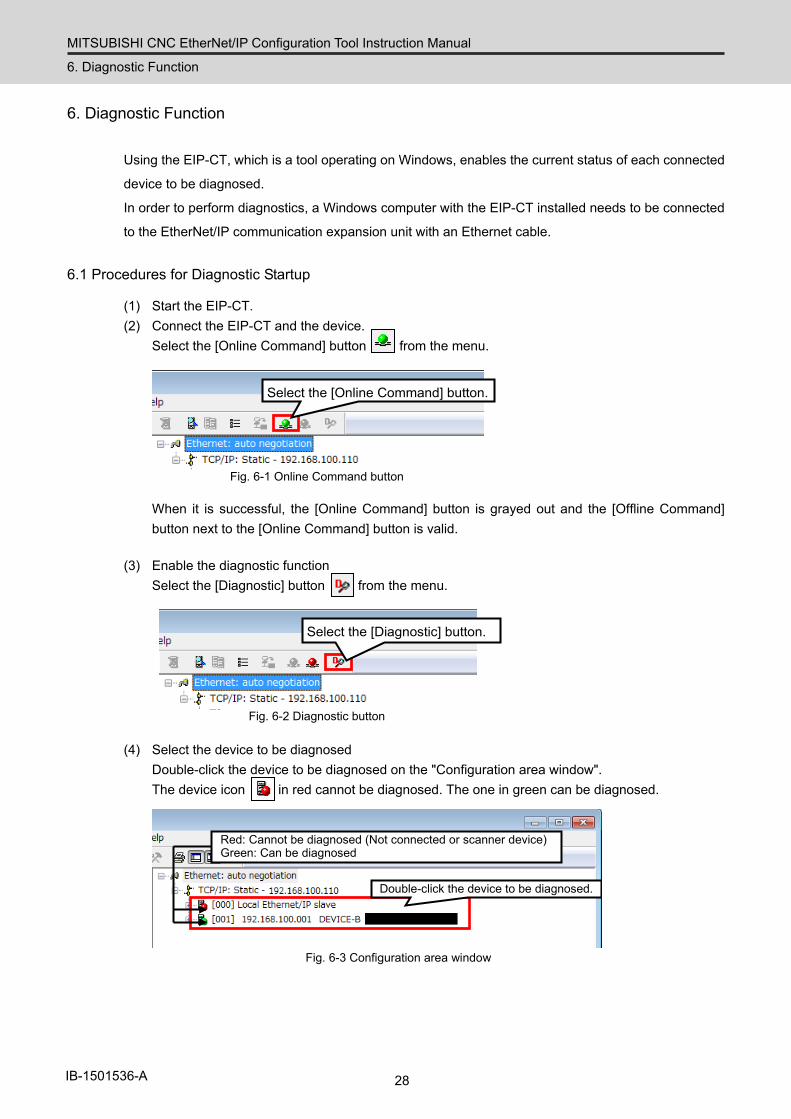
6.1 Procedures for Diagnostic Startup
(1) Start the EIP-CT. (2) Connect the EIP-CT and the device.
Select the [Online Command] button from the menu.
Select the [Online Command] button.
Fig. 6-1 Online Command button
When it is successful, the [Online Command] button is grayed out and the [Offline Command] button next to the [Online Command] button is valid.
(3) Enable the diagnostic function
Select the [Diagnostic] button from the menu.
Select the [Diagnostic] button.
Fig. 6-2 Diagnostic button
(4) Select the device to be diagnosed Double-click the device to be diagnosed on the "Configuration area window". The device icon in red cannot be diagnosed. The one in green can be diagnosed.
Double-click the device to be diagnosed.
Red: Cannot be diagnosed (Not connected or scanner device) Green: Can be diagnosed
Fig. 6-3 Configuration area window
MITSUBISHI CNC EtherNet/IP Configuration Tool Instruction Manual
6. Diagnostic Function
29 IB-1501536-A
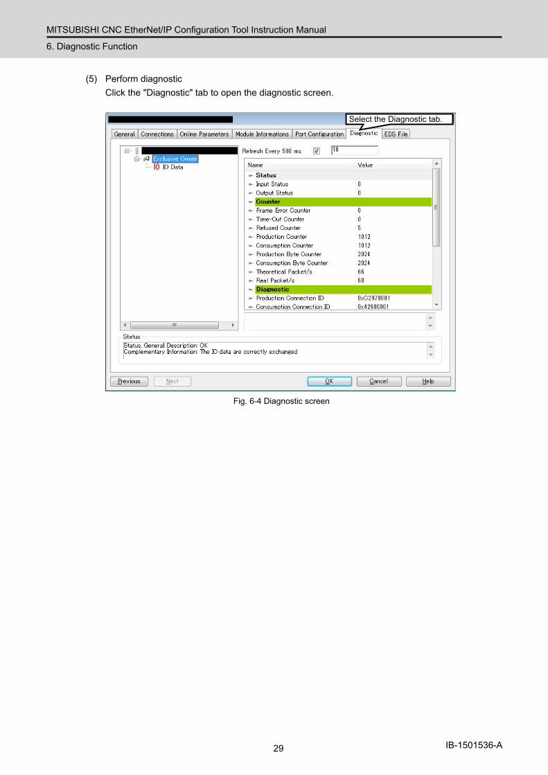
(5) Perform diagnostic Click the "Diagnostic" tab to open the diagnostic screen.
Select the Diagnostic tab.
Fig. 6-4 Diagnostic screen
MITSUBISHI CNC EtherNet/IP Configuration Tool Instruction Manual
6. Diagnostic Function
30 IB-1501536-A
6.2 Diagnostic Screen
There are two types of diagnostic screen: A screen for checking the current input/output status, and a
screen for checking the current I/O data.
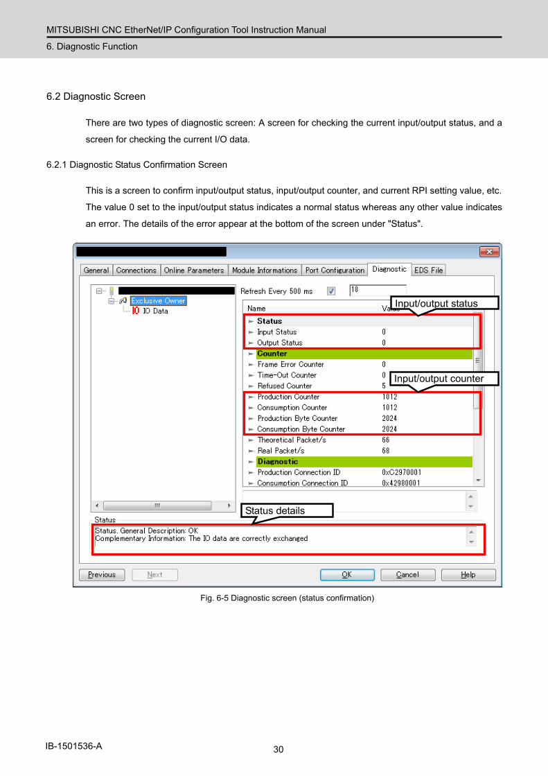
6.2.1 Diagnostic Status Confirmation Screen
This is a screen to confirm input/output status, input/output counter, and current RPI setting value, etc.
The value 0 set to the input/output status indicates a normal status whereas any other value indicates
an error. The details of the error appear at the bottom of the screen under "Status".
Input/output counter
Input/output status
Status details
Fig. 6-5 Diagnostic screen (status confirmation)
MITSUBISHI CNC EtherNet/IP Configuration Tool Instruction Manual
6. Diagnostic Function
31 IB-1501536-A
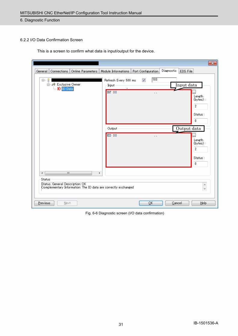
6.2.2 I/O Data Confirmation Screen
This is a screen to confirm what data is input/output for the device.
Output data
Input data
Fig. 6-6 Diagnostic screen (I/O data confirmation)
MITSUBISHI CNC EtherNet/IP Configuration Tool Instruction Manual
7. Compatible NC Versions
32 IB-1501536-A
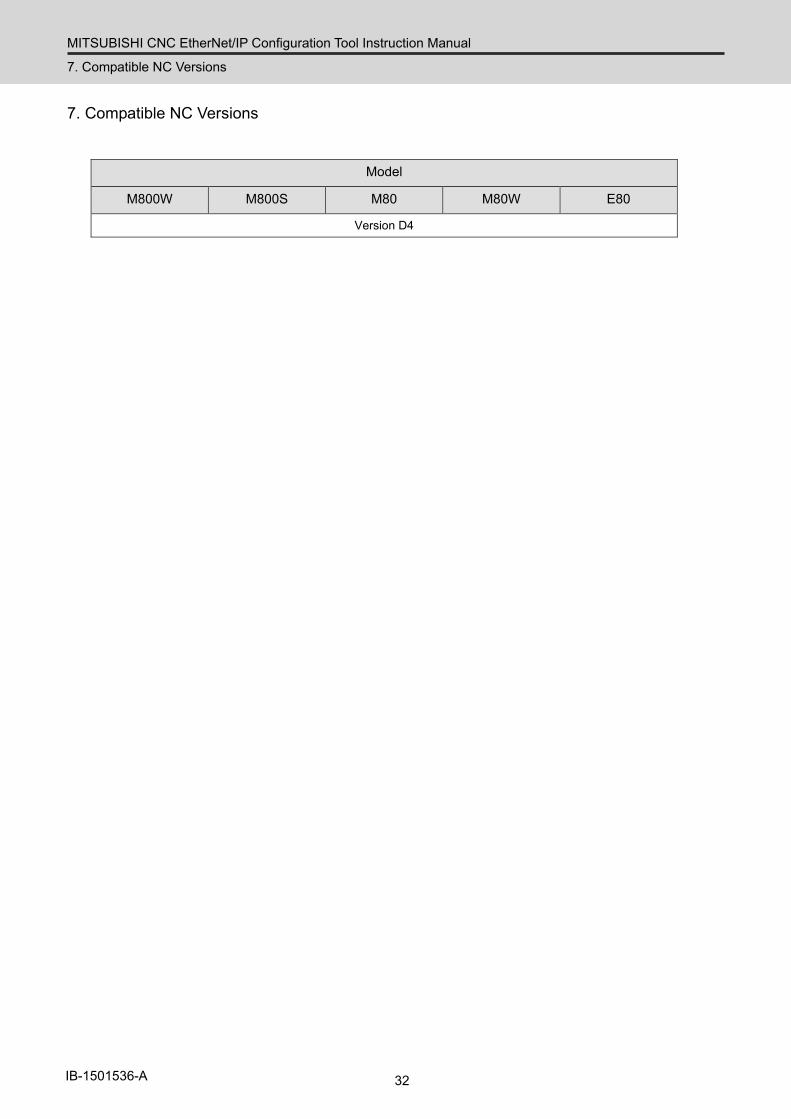
7. Compatible NC Versions
Model
M800W M800S M80 M80W E80
Version D4

Revision History
Date of revision Manual No. Revision details
Mar. 2018 IB(NA)1501536-A First edition created.
Global Service Network
AMERICA EUROPE
MITSUBISHI ELECTRIC AUTOMATION INC. (AMERICA FA CENTER) MITSUBISHI ELECTRIC EUROPE B.V. Central Region Service Center (Chicago) European Service Headquarter (Dusseldorf, GERMANY) 500 CORPORATE WOODS PARKWAY, VERNON HILLS, ILLINOIS 60061, U.S.A. Mitsubishi-Electric-Platz 1 40882 RATINGEN, GERMANY TEL: +1-847-478-2500 / FAX: +1-847-478-2650 TEL: +49-2102-486-1850 / FAX: +49-2102-486-5910 Minneapolis, MN Service Satellite Detroit, MI Service Satellite South Germany Service Center (Stuttgart) Grand Rapids, MI Service Satellite KURZE STRASSE. 40, 70794 FILDERSTADT-BONLANDEN, GERMANY Lima, OH Service Satellite TEL: + 49-711-770598-123 / FAX: +49-711-770598-141 Cleveland, OH Service Satellite Indianapolis, IN Service Satellite France Service Center (Paris) St. Louis, MO Service Satellite 25, BOULEVARD DES BOUVETS, 92741 NANTERRE CEDEX FRANCE
TEL: +33-1-41-02-83-13 / FAX: +33-1-49-01-07-25South/East Region Service Center (Georgia) 1845 SATTELITE BOULEVARD STE. 450, DULUTH, GEORGIA 30097, U.S.A. France Service Satellite (Lyon) TEL +1-678-258-4529 / FAX +1-678-258-4519 120, ALLEE JACQUES MONOD 69800 SAINT PRIEST FRANCE Charleston, SC Service Satellite TEL: +33-1-41-02-83-13 / FAX: +33-1-49-01-07-25 Charlotte, NC Service Satellite Raleigh, NC Service Satellite Italy Service Center (Milan) Dallas, TX Service Satellite VIALE COLLEONI, 7 - CENTRO DIREZIONALE COLLEONI PALAZZO SIRIO INGRESSO 1, Houston, TX Service Satellite 20864 AGRATE BRIANZA (MB), ITALY Hartford, CT Service Satellite TEL: +39-039-6053-342 / FAX: +39-039-6053-206 Knoxville, TN Service Satellite Nashville, TN Service Satellite Italy Service Satellite (Padova) Baltimore, MD Service Satellite VIA G. SAVELLI, 24 - 35129 PADOVA, ITALY Pittsburg, PA Service Satellite TEL: +39-039-6053-342 / FAX: +39-039-6053-206 Allentown, PA Service Satellite Syracuse, NY Service Satellite U.K. Service Center Tampa, FL Service Satellite TRAVELLERS LANE, HATFIELD, HERTFORDSHIRE, AL10 8XB, U.K. Lafayette, LA Service Satellite TEL: +49-2102-486-1850 / FAX: +49-2102-486-5910
Western Region Service Center (California) Spain Service Center 5900-B KATELLA AVE. - 5900-A KATELLA AVE. CYPRESS, CALIFORNIA 90630, U.S.A. CTRA. DE RUBI, 76-80-APDO. 420, 08173 SAINT CUGAT DEL VALLES, BARCELONA SPAIN TEL: +1-714-699-2625 / FAX: +1-847-478-2650 TEL: +34-935-65-2236 / FAX: +34-935-89-1579 San Francisco, CA Service Satellite Seattle, WA Service Satellite Poland Service Center
UL.KRAKOWSKA 50, 32-083 BALICE, POLANDCanada Region Service Center (Tronto) TEL: +48-12-347-6500 / FAX: +48-12-630-4701 4299 14TH AVENUE MARKHAM, ONTARIO L3R OJ2, CANADA TEL: +1-905-754-3805 / FAX: +1-905-475-7935 Hungary Service Center Edmonton, AB Service Satellite MADARASZ VIKTOR 47-49 , BUDAPEST XIII; HUNGARY Montreal, QC Service Satellite TEL: +48-12-347-6500 / FAX: +48-12-630-4701
Mexico Region Service Center (Queretaro) MITSUBISHI ELECTRIC TURKEY A.Ş Parque Tecnológico Innovación Querétaro, Lateral Carretera Estatal 431, Km 2+200, Lote 91 Modulos 1 y 2 Turkey Service Center Hacienda la Machorra, CP 76246, El Marqués, Querétaro, México SERIFALI MAHALLESI NUTUK SOKAK. NO.5 34775 TEL: +52-442-153 4250 UMRANIYE, ISTANBUL, TURKEY Monterrey, NL Service Satellite TEL: +90-216-526-3990 / FAX: +90-216-526-3995 Mexico City, DF Service Satellite
Czech Republic Service Center AutoCont Control Systems s.r.o (Service Partner) KAFKOVA 1853/3, 702 00 OSTRAVA 2, CZECH REPUBLIC
BRAZIL TEL: +420-59-5691-185 / FAX: +420-59-5691-199
Mitsubishi Electric do Brasil Comércio e Serviços Ltda. Russia Service CenterVotorantim Office NC-TECH (Service Partner) AV. GISELE CONSTANTINO,1578, PARQUE BELA VISTA, VOTORANTIM-SP, BRAZIL CEP:18.110-650 213, B.NOVODMITROVSKAYA STR., 14/2, 127015 MOSCOW, RUSSIA TEL: +55-15-3023-9000 TEL: +7-495-748-0191 / FAX: +7-495-748-0192 JOVIMAQ – Joinville, SC Service Satellite MAQSERVICE – Canoas, RS Service Satellite Sweden Service Center
HAMMARBACKEN 14, P.O.BOX 750 SE-19127, SOLLENTUNA, SWEDEN TEL: +46-8-6251000 / FAX: +46-8-966877
Bulgaria Service Center AKHNATON Ltd. (Service Partner) 4 ANDREJ LJAPCHEV BLVD. POB 21, BG-1756 SOFIA, BULGARIA TEL: +359-2-8176009 / FAX: +359-2-9744061
Ukraine Service Center (Kharkov) CSC Automation Ltd. (Service Partner) APTEKARSKIY PEREULOK 9-A, OFFICE 3, 61001 KHARKOV, UKRAINE TEL: +380-57-732-7774 / FAX: +380-57-731-8721
Belarus Service Center TECHNIKON Ltd. (Service Partner) NEZAVISIMOSTI PR.177, 220125 MINSK, BELARUS TEL: +375-17-393-1177 / FAX: +375-17-393-0081
South Africa Service Center MOTIONTRONIX (Service Partner) P.O. BOX 9234, EDLEEN, KEMPTON PARK GAUTENG, 1625, SOUTH AFRICA TEL: +27-11-394-8512 / FAX: +27-11-394-8513
ASEAN CHINA
MITSUBISHI ELECTRIC ASIA PTE. LTD. (ASEAN FA CENTER) MITSUBISHI ELECTRIC AUTOMATION (CHINA) LTD. (CHINA FA CENTER)Singapore Service Center China Shanghai Service Center 307 ALEXANDRA ROAD #05-01/02 MITSUBISHI ELECTRIC BUILDING SINGAPORE 159943 1-3,5-10,18-23/F, NO.1386 HONG QIAO ROAD, CHANG NING QU, TEL: +65-6473-2308 / FAX: +65-6476-7439 SHANGHAI 200336, CHINA
TEL: +86-21-2322-3030 / FAX: +86-21-2322-3000*8422Philippines Service Center China Ningbo Service Partner Flexible (Service Partner) China Wuxi Service Partner UNIT NO.411, ALABAMG CORPORATE CENTER KM 25. WEST SERVICE ROAD China Jinan Service Partner SOUTH SUPERHIGHWAY, ALABAMG MUNTINLUPA METRO MANILA, PHILIPPINES 1771 China Hangzhou Service Partner TEL: +63-2-807-2416 / FAX: +63-2-807-2417
China Beijing Service Center 9/F, OFFICE TOWER 1, HENDERSON CENTER, 18 JIANGUOMENNEI DAJIE,
VIETNAM DONGCHENG DISTRICT, BEIJING 100005, CHINA TEL: +86-10-6518-8830 / FAX: +86-10-6518-8030
MITSUBISHI ELECTRIC VIETNAM CO.,LTD China Beijing Service PartnerVietnam Ho Chi Minh Service Center UNIT 01-04, 10TH FLOOR, VINCOM CENTER 72 LE THANH TON STREET, DISTRICT 1, China Tianjin Service Center HO CHI MINH CITY, VIETNAM UNIT 2003, TIANJIN CITY TOWER, NO 35 YOUYI ROAD, HEXI DISTRICT, TEL: +84-8-3910 5945 / FAX: +84-8-3910 5946 TIANJIN 300061, CHINA
TEL: +86-22-2813-1015 / FAX: +86-22-2813-1017Vietnam Hanoi Service Center 6TH FLOOR, DETECH TOWER, 8 TON THAT THUYET STREET, MY DINH 2 WARD, China Chengdu Service Center NAM TU LIEM DISTRICT, HA NOI CITY, VIETNAM 1501-1503,15F,GUANG-HUA CENTRE BUILDING-C,NO.98 NORTH GUANG HUA 3th RD, TEL: +84-4-3937-8075 / FAX: +84-4-3937-8076 CHENGDU,610000,CHINA
TEL: +86-28-8446-8030 / FAX: +86-28-8446-8630
INDONESIA China Shenzhen Service Center ROOM 2512-2516, 25/F., GREAT CHINA INTERNATIONAL EXCHANGE SQUARE, JINTIAN RD.S.,
PT. MITSUBISHI ELECTRIC INDONESIA FUTIAN DISTRICT, SHENZHEN 518034, CHINAIndonesia Service Center (Cikarang) TEL: +86-755-2399-8272 / FAX: +86-755-8229-3686 JL. KENARI RAYA BLOK G2-07A, DELTA SILICON 5, LIPPO CIKARANG - BEKASI 17550, INDONESIA China Xiamen Service Partner TEL: +62-21-2961-7797 / FAX: +62-21-2961-7794 China DongGuang Service Partner
China Dalian Service Center MALAYSIA DONGBEI 3-5, DALIAN ECONOMIC & TECHNICAL DEVELOPMENTZONE, LIAONING PROVINCE,
116600, CHINAMITSUBISHI ELECTRIC SALES MALAYSIA SDN. BHD. TEL: +86-411-8765-5951 / FAX: +86-411-8765-5952Malaysia Service Center (Kuala Lumpur Service Center) LOT 11, JALAN 219, P.O BOX 1036, 46860 PETALING JAYA, SELANGOR DARUL EHSAN. MALAYSIA TEL: +60-3-7960-2628 / FAX: +60-3-7960-2629 KOREA Johor Bahru Service satellite
MITSUBISHI ELECTRIC AUTOMATION KOREA CO., LTD. (KOREA FA CENTER)Korea Service Center
THAILAND 8F GANGSEO HANGANG XI-TOWER A, 401 YANGCHEON-RO, GANGSEO-GU, SEOUL 07528 KOREA
MITSUBISHI ELECTRIC FACTORY AUTOMATION (THAILAND) CO.,LTD TEL: +82-2-3660-9609 / FAX: +82-2-3664-8668Thailand Service Center Korea Daegu Service Satellite 12TH FLOOR, SV.CITY BUILDING, OFFICE TOWER 1, NO. 896/19 AND 20 RAMA 3 ROAD, KWAENG BANGPONGPANG, KHET YANNAWA, BANGKOK 10120,THAILAND TEL: +66-2-682-6522 / FAX: +66-2-682-6020 TAIWAN
MITSUBISHI ELECTRIC TAIWAN CO., LTD. (TAIWAN FA CENTER) INDIA Taiwan Taichung Service Center
NO.8-1, INDUSTRIAL 16TH RD., TAICHUNG INDUSTRIAL PARK, SITUN DIST., MITSUBISHI ELECTRIC INDIA PVT., LTD. TAICHUNG CITY 40768, TAIWANCNC Technical Center (Bangalore) TEL: +886-4-2359-0688 / FAX: +886-4-2359-0689 PLOT NO. 56, 4TH MAIN ROAD, PEENYA PHASE 3, PEENYA INDUSTRIAL AREA, BANGALORE 560058, KARNATAKA, INDIA Taiwan Taipei Service Center TEL : +91-80-4655-2121 FAX : +91-80-4655-2147 10F, NO.88, SEC.6, CHUNG-SHAN N. RD., SHI LIN DIST., TAIPEI CITY 11155, TAIWAN Chennai Service Satellite TEL: +886-2-2833-5430 / FAX: +886-2-2833-5433 Coimbatore Service Satellite Hyderabad Service Satellite Taiwan Tainan Service Center
11F-1., NO.30, ZHONGZHENG S. ROAD, YONGKANG DISTRICT, TAINAN CITY 71067, TAIWANNorth India Service Center (Gurgaon) TEL: +886-6-252-5030 / FAX: +886-6-252-5031 2ND FLOOR, TOWER A&B, DLF CYBER GREENS, DLF CYBER CITY, DLF PHASE-III, GURGAON- 122 002, HARYANA, INDIA TEL : +91-124-4630 300 FAX : +91-124-4630 399 OCEANIA Ludhiana Satellite Panth Nagar Service Satellite MITSUBISHI ELECTRIC AUSTRALIA PTY. LTD. Delhi Service Satellite Oceania Service Center Jamshedpur Service Satellite 348 VICTORIA ROAD, RYDALMERE, N.S.W. 2116 AUSTRALIA
TEL: +61-2-9684-7269/ FAX: +61-2-9684-7245West India Service Center (Pune) EMERALD HOUSE, EL-3, J BLOCK, M.I.D.C., BHOSARI, PUNE - 411026, MAHARASHTRA, INDIA TEL : +91-20-2710 2000 FAX : +91-20-2710 2100 Kolhapur Service Satellite Aurangabad Service Satellite Mumbai Service Satellite
West India Service Center (Ahmedabad) UNIT NO: B/4, 3RD FLOOR, SAFAL PROFITAIRE, PRAHALADNAGAR CORPORATE ROAD, PRAHALADNAGAR SATELLITE, AHMEDABAD – 380015, GUJRAT, INDIA TEL : +91-265-2314699 Rajkot Service Satellite
Notice
Every effort has been made to keep up with software and hardware revisions in the contents described in this manual. However, please understand that in some unavoidable cases simultaneous revision is not possible.
Please contact your Mitsubishi Electric dealer with any questions or comments regarding the use of this product.
Duplication Prohibited This manual may not be reproduced in any form, in part or in whole, without written permission from Mitsubishi Electric Corporation.
2018 MITSUBISHI ELECTRIC CORPORATION ALL RIGHTS RESERVED.