mit radiation lab series, v2, radar aids to navigation
DESCRIPTION
MIT Radiation Laboratory Series, Radar Aids to Navigation - Volume 2, 1947TRANSCRIPT

PART I
INTRODUCTION

CHAPTER 1
PRINCIPLES OF RADAR
BY J. S: HALL, J. P. NASH, D. HALLIDAY, R. M. WHITMER,R. E. MEAGHER, AND J. B. PLA’rr
Before we discuss how radar can help us solve problems in navigation,we should first describe how radar works. This chapter gives the com-mon background of knowledge needed for use in the three main divisionsof this book, airborne radar, ground-based radar, and shipborne radar.
HOW RADAR WORKS
BY J. S. HALL
101. The Fundamental Ideaa.—There are a number of situationswhere men or animals cannot see clearly but succeed, nevertheless, infinding their way about. They do this by making sounds and thendetecting echoes from solid objects still some distance away. Theechoes are used as guides. Many blind persons, for instance, develop inthe course of time a considerable ability to avoid obstacles by means ofauditory cues received from sounds of their own making, like footstepsor the tapping of a cane. Their skill is often drastically impaired iftheir hearing is blocked by ear plugs or by distracting noises. Bats canfly through the total darkness of caves without striking the walls orjutting stalactites which may be in their way. This is possible becausethey emit a supersonic cry—inaudible to human ears because its fre-quency is from 30,000 to 70,000 cps—and orient themselves by means ofthe echoes of this cry, which return to them from any obstacles whichlie ahead.l
The experimental evidence2 which forms the basis of these conclusionsmakes fascinating reading. It has been demonstrated conclusively thata bat loses his uncanny ability to navigate in the dark if his mouth istied shut or hk hearing impaired. The rate at which he producessupersonic cries has been shown to increase according to a definite pat-tim (always to the advantage of the bat) as he approaches obstacles inhis path. These facts, combined with the special anatomical character-
1D. R. Grifiin,Sciewx, 100, 589-590 (1944).2D. R. Gri5 and R. Galambos,Jour. Ezp. Zool., 86, 481–505(1941).
3
4 PRINCIPLES OF RADAR [SEC.1.1
istics of their larynges and ears, indicate strongly that bats use thegeneral principle of radar as an aid to navigation.
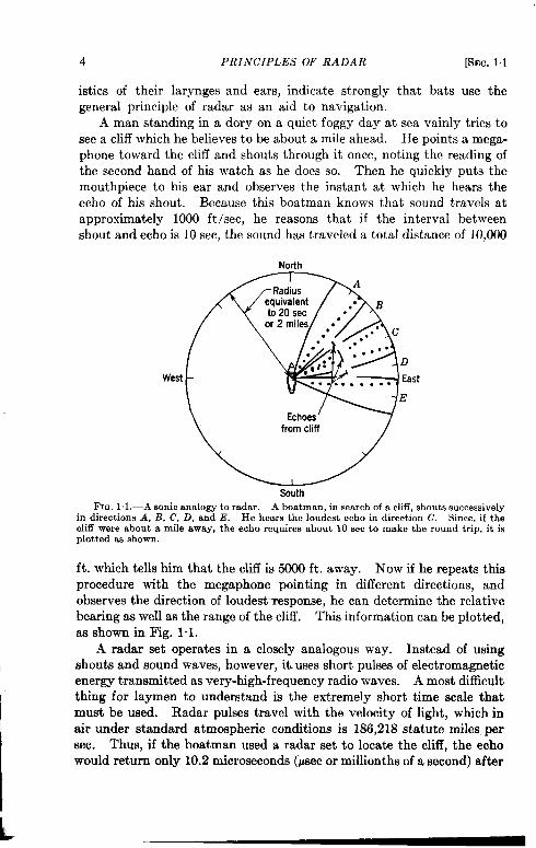
A man standing in a dory on a quiet foggy day at sea vainly tries tosee a cliff which he believes to be about a mile ahead. He points a mega-phone toward the cliff and shouts through it once, noting the reading ofthe second hand of his watch as he does so. Then he quickly puts themouthpiece to his ear and observes the instant at which he hears theecho of his shout. Because this boatman knows that sound travels atapproximately 1000 ft /see, he reasons that if the interval betweenshout and echo is 10 see, the sound has traveled a total distance of 10,000
North
West
SouthFIO.1.1.—A sonicanalogyto radar, A boatman, in search of a cli5, shouts successively
in directions A, 1?, C, D, and E. He hears the loudest echo in direction C, Since, if thecliff were about a mife away, the echo requires about 10 sec to make the round trip, it isplotted as shown.
ft. which tells him that the cliff is 5000 ft. away. Now if he repeats thisprocedure with the megaphone pointing in different directions, andobserves the direction of loudest~esponse, he can determine the relativebearing as well as the range of the cliff. This information can be plotted,as shown in Fig. 1.1.
A radar set operates in a closely analogous way. Instead of usingshouts and sound waves, however, iti uses short pulses of electromagneticenergy transmitted as very-high-frequency radio waves. A most difficultthing for laymen to understand is the extremely short time scale thatmust be used. Radar pulses travel with the velocity of light, which inair under standard atmospheric conditions is 186,218 statute miles, persec. Thus, if the boatman used a radar set to locate the cliff, the echowould return only 10.2 microseconds (Psec or millionths of a second) after
....
SEC.11] THE FUNDAMENTAL IDEAS 5
the pulse was transmitted. This is about one milhonth of the timerequired for sound to travel the same distance.
Such short time intervals must be measured by electronic methods.As each puke is transmitted, a small spot starts to move at a uniformspeed radially outward from the center of the face of a cathode-ray tube.If no echo were received, that is, if the radar pulse did not bounce backfrom an object in its path, it would trace a faint line of uniform intensityon the face of the tube. But if an echo is received—if the radar pulsedoes bounce back from an object-it intensifies this spot and brightensmomentarily a short segment of the line. If several hundred pulses persecond are transmitted, and this process is repeated for each pulse, theechoes from these pulses repeatedly brighten the same segment on theface of the cathode-ray tube, making a steady spot of light.
The antenna which radiates the pulses directs the electromagneticenergy into a narrow beam, like that of a searchlight. If thk antenna isrotated slowly in azimuth, and if the direction the radial line makes onthe tube face is rotated in synchronism with it, the position of the spotof light on the tube face will show both the direction and range of theobject the radar set is looking for—in this case, the cliff.
The problem of locating an object with radar, then, is a dual one.The time it takes each pulse to reach an object and return must bemeasured accurately. An indication of the direction in which eachpulse is propagated must be presented simultaneously in an easily under-standable form. Ways in which such information is obtained are dis-cussed in later sections. The most widely used way in which thisinformation is presented is the plan position indicator, or PPI, which isdescribed below.
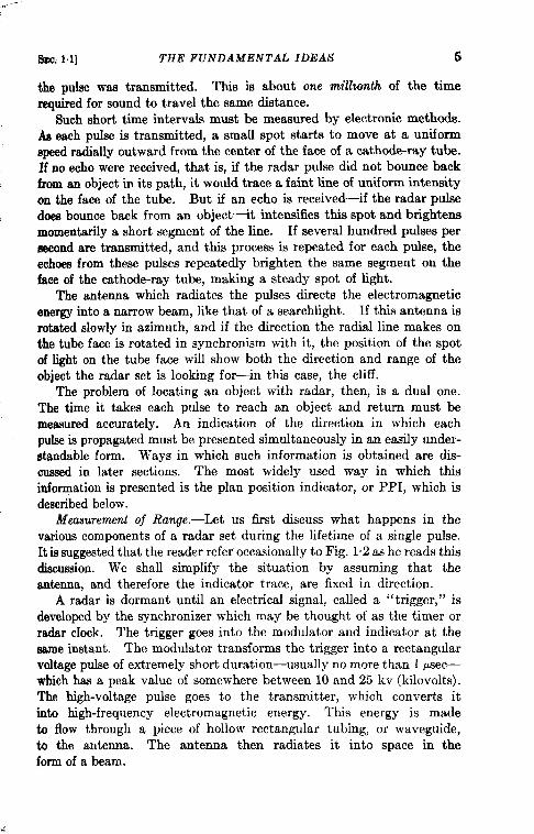
Measurement of Range.-Let us first discuss what happens in thevarious components of a radar set during the lifetime of a single pulse.It is suggested that the reader refer occasionally to Fig. 1“2 as he reads thisdiscussion. We shall simplify the situation by assuming that theantenna, and therefore the indicator trace, are fixed in direction.
A radar is dormant until an electrical signal, called a “tzigger,” isdeveloped by the synchronizer which may be thought of as the timer orradar clock. The trigger goes into the modulator and indicator at thesame instant. The modulator transforms the trigger into a rectangularvoltage pulse of extremely short duration—usually no more than 1 psec—which has a peak value of somewhere between 10 and 25 kv (kilovolts).The high-voltage pulse goes to the transmitter, which converts itinto high-frequency electromagnetic energy. This energy is madeto flow through a piece of hollow rectangular tubing, or waveguide,to the antenna. The antenna then radiates it into space in theform of a beam.
6 PRINCIPLES OF RADAR [SEC. 1.1
All this can happen in less than 1 Keec because electrical energytravels along conductors with a speed only slightly less than that of lightin vacuo.1 Thk slug of electromagnetic energy radiated by the antennafor a period of 1 Psec contains a large number of waves whose lengths
Azimuthdb(electrical)
Trans-“ mittar
Trigger\ Pathof, Transm”M pulse R~eiver =h:r~lses
Synchro-nizer
‘Siinal voltage1,
Trigge~> pulses(video)
Elactriilmngemarkers
Planpositionindicator
Fm. 1.2.—Radar block diagram showing the components packaged in a common form.
are very short, compared to ordinary radio waves. For a l-psec pulse,the distance between the leading and trailing edges of this wavetrain inempty apace is 984 ft.
I A very special switching arrangementallows the transmitted pulse to psasthroughthe waveguideto the antennaat high power levels,while,at the sametime,it prevents all but a very smallportion of the pulsefrom leakinginto the rsceiver.Then, in a matterof 1 or 2 psec,the switchdisconnectsthe antennafrom the trans-mitterand recormcctsit to the receiver.
SEC.1.1] THE FUNDAMENTAL IDEAS 7
After the energy has been tranami tted, extremely d portiona of itare reflected back toward the antenna by a greatvariety of objects.Successive echoes strike the antenna and are then fed back through thewaveguide to the receiver. The receiver performs the reverse functionof the transmi tter, but at very low energy levels; that is, it transformsthe extremely weak pulses of high-frequency electromagnetic wavesreflected from the various targets within the antenna beam back intovoltage pulses. In doing so, it amplifies them many times before pawingthem onto the indicator, as so-called “video” signals, at a voltage levelof a few volts. 1
The reader will recall that as the trigger goes to the modulator itsimultaneously goes to the indicator. In the indicator, the triggercauses a beam of electrons to strike from behind the center of a lumi-nescent screen which backs the face of a large cathode-ray tube. If thisbeam were stationary, the observer would see a bright spot. As a pulseof electromagnetic energy goes out from the antenna, this beam ofelectrons moves radially at a constant speed toward the edge of the tubeand a faint line is generated on the luminescent screen. This process isillustrated in Fig. 13.
The intensity of this beam of electrons is increased considerably andthe line brightened momentarily whenever signals are received. Theobserver, therefore, sees a series of brightened spots on this line. Thedistance of any one of these spots from the center of the tube is a measureof the time it took the radio waves to travel to the various targets andback. Since it requires 10.7 Psec for a pulse to reach a target a mileaway and return from it, it is evident that the time required by a pulseto reach any target and return divided by 10.7 gives the range to thetarget in statute miles.
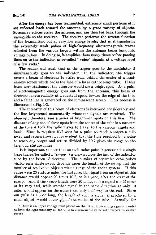
It is important to note that as each radar pulse is generated, a singletrace (hereafter called a “sweep”) is drawn across the face of the indicatortube by the beam of electrons. The number of separable echo pulsesvisible on a single sweep depends upon the length of the sweep and thenumber of resolvable objects within range of the radar system. If thisrange were 20 statute miles, for instance, the signal from an object at thisdistance would appear 20 times 10.7, or 214 psec, after the start of thesweep. And if the sweep length were 20 miles, such a signal would occurat its very end, while another signal in the same direction at only 10miles would appear on the same trace only half way to the end. Sinceour pulse is 1 ~sec long, the length of such a signal, if produced by asmall object, would cover ~ of the radius of the tube. Actually, for
1 There is an upper voltage limit placed on the return from strong signals in orderto limit the light intensity on the tube to a reasonable value with respect to weakerechoes,
8 PRINCIPLES OF RADAR [SEC. 1.1
this sweep length it may be somewhat longer because the signal cannotbe smaller than the inherent diameter of the luminescent spot.
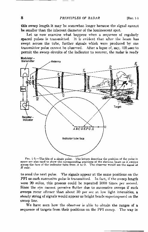
Let us now examine what happens when a sequence of regularlyspaced pulses is transmitted. It is evident that after the beam hasswept across the tube, further signals which were produced by onetransmitter pulse cannot be observed. After a lapse of, say, 100 psec topermit the sweep circuits of the indicator to recover, the radar is ready
Madulator -transmitter , Anten na m
FIG. 1.3.—The life of a single pulse. The letters denoting the position of the pulse inspace are also used to show the corresponding positions of the electron beam as it sweepsacroes the face of the indicator tube from A to0. The observer would see the gignal atH Ody.
to send the next pulse. The signals appear at the same positions on thePPI as each successive pulse is transmitted. In fact, if the sweep lengthwere 20 miles, this process could be repeated 3000 times per second.Since the eye cannot perceive flutter due to successive sweeps if suchsweeps recur oftener than about 30 per sec at low light intensities, asteady string of signals would appear as bright beads superimposed on thesweep line.
We have seen how the observer is able to obtain the ranges of asequence of targets from their positions on the PPI sweep. The way in
I%!.c.1.1] THE FUNDAMENTAL IDEAS 9
which he measures these positions depends on the complexity of the
The simplest procedure is to place a suitably engraved transparentdisk over the face of the tube. A more elaborate arrangement is one inwhich range markers are generated electrically at regular intervals aftereach transmitted pulse, the first marker always occurring simultaneouslywith the trigger from the synchronizer.
If now we imagine the sweep rotating in synchronism with the antennait should be evident that these electronic markers would trace concentriccircles on the face of the tube. On fast sweeps it is usually possible toestimate the range of a target with an average error of no more than+ mile.
Measurement of Bearing. -We will now see how signals appear whenthe antenna and sweeps rotate together. It is desirable first to pointout certain important general features of the indicator tube itself. 1
A deflection coil is so mounted as to surround the glass neck of acathode-ray tube. The current through this coil begins to rise as eachpuke is transmitted. The current in the coil changes in such a way thatthe electron beam is deflected at a uniform rate from the center to theedge of the tube. The direction taken by this sweep corresponds directly tothe orientation of the cod. Consequent] y, if the coil is rotated mechani-cally in synchronism with the antenna, each sweep would take a slightlydifferent direction, which corresponds to that of the antenna. Anelectrical linkage system, known as a ‘‘ servomechanism” (Sec. 1.7), iscommonly used to keep the coil orientation in step with the antenna. Itis customary to orient this coil in such a way that the sweep assumesthe “ 12 o’clock” position when the antenna is pointed north and torotate the antenna from north to east so that the sweeps rotate clockwise.
The number of pulses per second and the speed of antenna rotationare set at such rates that successive sweeps are barely resolved at theouter edge of the tube. Near the center they overlap.
As the direction of the sweeps changes around the face of the tube,bright bluish-white signals appear along each sweep. Although thesesignals decrease rapidly in intensity to a yellow glow, they persist longenough to produce a maplike picture of the region immediately surround-ing t,heantenna. Individual landmarks are revealed only in their grossdimensions. As the antenna rotates, they reappear continuously a~ thesame places on the tube face if the relative position of target and radaris fixed.
The bearing of any particular object may be determined by bisectingits signal on the tube face with a cursor (a radial line inscribed on a
1A moredetailed description of the cathode-ray tube and various types of indi-eatme is given toward the end of this chapter.
10 PRINCIPLES OF RADAR [SEC. 1.2
transparent overlay) which can be rotated manually about an axiscoincident with the center of the tube face, and then reading the corre-sponding bearing on a circular scale at its periphery. A simpler methodis to use a transparent overlay with bearing lines and figures engravedon the side next to the tube face. Angle markers can be displayedelectronically by brightening a few successive sweeps at intervals of-10° or 15°.
1“2. Resolution, Accuracy, and Coverage. Range Resolution, Mini-mum Ra~e, and Ra~e Accuracy .-The range resolution of a radar is theminimum resolvable separation in the range of two targets. It dependson the length of the transmitted pulse, the characteristics of the receiverand indicator, and the type of target. A pulsed radar transmitter doesnot transmit on a single frequency, but rather on a narrow band of fre-quencies. The width of the band in which most of the energy is trans-mitted is inversely proportional to the pulse length; it is about 2 Mc(megacycles) wide for a 1 psec pulse and 8 Mc for a ++sec pulse.
The intermechate-frequehcy amplifier of the receiver must be capableof amplifying energy distributed over this range of frequencies so thatmost of the detected energy can be profitably presented on the indicator.This range of frequencies—the so-called “pass band” of the receiver-must be tailored to the pulse length. If it is too wide, backgroundeffects or “noise” might drown out weak signals entirely. It is not yetpractical to use pulses that are much shorter than 0.1 psec.
After the amplified signals in the receiver have been rectified intovoltage pulses, they are again amplified and limited in voltage beforegoing to the indicator. This last amplification is accomplished in a so-called “video amplifier.” Its pass band should beat least half that of theintermediate-frequency amplifier mentioned above if the full range-measuring capabilities of the radar are to be realized.
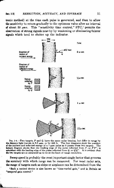
The range resolution of a particular radar system cannot be statedexactly without actual tests on different types of targets. With a well-designed radar, sharply defined targets at the same bearing should beresolved if their ranges differ by the distance light travels in a time equalto half the pulse length. Figure 14 shows that two targets should beresolvable with a radar generating 1-PSCCpulses if the targets are separatedin range by the distance light travels in + psec, which is 492 ft. Anexperienced observer can sometimes resolve certain types of targetsseparated by less than this distance.
The minimum range at which signals can be detected depends onmany factors. An experimental radar system has been made whoseminimum detectable range is only a few feet; the effective minimum rangefor most radars is between 200 and 1000 ft. In surface-based radars it iscustomary to reduce the receiver sensitivity considerably (by an elec-
SEC. 1,2] RESOLUTION,
tronic method) at the time
ACCURACY, AND COVERAGE 11
each pulse is generated, and then to allowthe sensitivity to return gradually to the optimum value after an intervalof about 50 psec. This “sensitivityy time control,” STC,’ permits theobservation of strong signals near-by by weakening or eliminating faintersignals which tend to clutter up the indicator.
Oirectionofmdlon ofre$cted energy
P’!
........ ............,.:,.: ....,:.:,’:.,....4
,........“:: : ‘*.+;
Energy
H
. ..>; :;.. Qreflected ..,.::,..... ... >,..’.::.:>
by P -;?”J..... .. ,=,.2... ..: ., .:,..Energyreflected ❑ >>:-..:”::“’ ‘“”L
by Q
FIG.14.-Two targets, P andQ, havethe sameradarbearing,but differin rangebythedietancelighttravelsin 0.5 psec, or by 492 ft. The four diagrams show the pogitionof the incident and reflected energy of a l-psec pulse as it paw-esthese two targets. Thebottom diagramshows that the traifing edge of the pulse reflected from P, or P’P”, iscoincidentwiththeleadingedgeof thepulsereflectedfromQ,or Q’,Q”. It is evidentthatthetwotargeteareso separatedas to be at thelimitof rangeresolution.
Sweep speed is probably the most important single factor that governsthe accuracy with which range can be measured. For most radar sets,the range of targets such as ships or airplanes can be determined from the
1Sucha control device is also known as ‘(time-varied gain,” and in Britain as“temporalgain control.”
12 PRINCIPLES OF RADAR [SEC. 1.2
PPI tube face to within about an eighth of a mile. BY projecting virtualimages of maps onto the PPI (see Sec. 9“6), it is possible, with fast sweeps,to determine range with errors of 150 ft or less. Radar systems thatcan determine range to within 10 or 15 ft have been designed for specialpurposes.
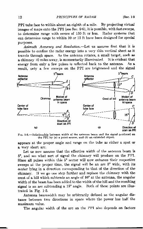
Azimuth Accuracy and Resolution.—Let us assume first that it ispossible to confine the radar energy into a very thin vertical sheet as ittravels through space. As the antenna rotates, a small target, such asa chimney 10 miles away, is momentarily illuminated. It is evident thatenergy from only a few pulses is reflected back to the antenna. As aresufi~ only a few sweeps on the PPI are brightened and the signal
I Motion’ ofChimney antenna beam
Iin space
Center oftube fete
/ . ..-.------T.:--5$---=-—-—_ ________
DirectionBofscan on PPI
(a)
5°beam
-I Motioiof
Crest of hill antenna ~am
I
in-3paceCenter of ctube face
~g
Lay:--::::------ ----;;”-----
------
B
(b) Direction ofscan on PPI
Fm. l&-Relationship between width of the antenna beam and the signal PIeduced onthe PPI by (a) a point source, and (b) an extended object.
appears at the proper angle and range on the tube as either a spot ora very short arc.
Let us now assume that the effective width of the antenna beam is5°, and see what sort of signal the chimney will produce on the PPI.Since all pulses within this 5° sector will now enhance their respectivesweeps at the proper time, the signal will be an arc 5° wide, with itscenter lying in a direction corresponding to that of the direction of thechimney. If we go one step further and replace the chimney with thecrest of a hill which subtends an angle of 10° at the antenna, the angularwidth of the beam has been added to the width of the hill and the resultingsignal is an arc subtending a 15° angle. Both of these points are illus-trated in Fig. 1.5.
Antenna beamwidth may be arbitrarily defined as the angular dis-tance between two directions in space where the power has half themaximum value.
The angular width of the arc on the PPI also depends on factors
SEC.1.2] RESOLUTION, ACCURACY, AND COVERAGE 13
other than beamwidth. All antennas radiate small amounts of powerindirection other than that of the main lobe. Flanking the main lobeon each side, there may be one or two so-called “side lobes” which con-tain less than 2 per cent of the ener~ in the main lobe. In some casesthis is sufficient to produce from a single target two or more signalsplaced symmetrically on each side of the main image. A very large,distant target, such as a ship standing broadside to the radar beam, ord close targets, may even produce semi-circular arcs on the PPI.
The observer can often eliminate these effects by reducing the gain(amplification) of the radar receiver until only the signal voltage fromthe center of the main lobe is strong enough to show on the PPI. Whenthis b done, however, the receiver can no longer detect very weak signals.
It has already been mentioned that sensitivity time control, STC,can automatically turn down the receiver gain for the first few miles ofsignals and thereby permit only the stronger ones to be resolved. Forall but shipbome radars, ground signals are not only very numerous but,because they are near and therefore strong, they are usually much broaderthau normal and often tend to clutter up the PPI. Although STC is ahelpful device, other and more effective methods of eliminating theundesirable effects of nearby signals can be used. Such methods arediscussed in Sees. 5.1 and 7.9.
It is diilicult to discuss azimuth resolution without again mentioningrange resolution. Targets appearing at the same bearing but differingin range by 500 ft usually can be seen separately on a fast sweep whenpulses of 1 psec or Iesaare used. This is true regardless of whether the twotargets are 6 or 60 miles away, although in the latter case the beginningof the fast sweep must be delayed. When each target can be seen sep-arately, its arc can be bisected by the cursor and its bearing determinedto about one-tenth the width of the radar beam. With our typical be~-width of 5“, the bearing of each target can be found to 0.5°. This valuecorresponds to+ mile at 57 miles-in other words, at 57 miles the positionof each target can be determined to within 500 ft in range and + milein a direction perpendicular to the line of sight. This latter uncertaintywould decrease to + mile (or 264 ft) at 5.7 miles. It is evident fromthis discussion that radar is particularly effective in range resolution.
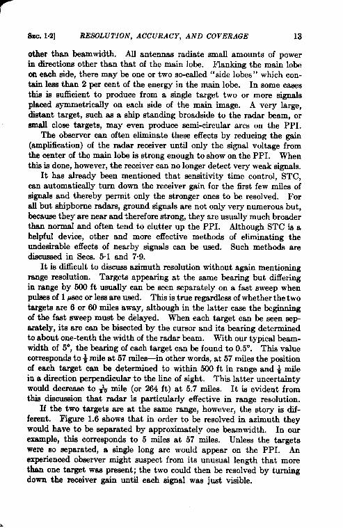
If the two targets are at the same range, however, the story is dif-ferent. F@we 1.6 shows that in order to be resolved in azimuth theywould have to be separated by approximately one beamwidth. In our
example, this corresponds to 5 miles at 57 miles. Unless the targetswere so separated, a single long arc would appear on the PPI. Anexperienced observer might suspect from its unusual length that morethan one target was present; the two could then be resolved by turningdown the receiver gain until each signal was just tilble.
14 PRINCIPLES OF RADAR [SEC.1.2
It is evident, therefore, that high range resolution (short pukes andfast sweeps) will tend to compensate for the disadvantages of a wideantenna beam. This compensation is more important for surface-basedradars than for airborne systems. It is also true that the antenna patternshould be made as sharp as possible in order to keep the signals small onthe indicator tube. The problem of identifying landmarks, particularlywith airborne sets, can in this way be made less difficult.
Relaiion between Beamwidth, Antenna Size, and [email protected] canbe shown theoretically that the beamwidth (in radians) for a circularaperture is given roughly by the expression 1.2 h/D, where x is the wave-length employed and D is the diameter of the aperture. This expression
=01.,,.,....
D
Antenna
,,/
‘
Center of PPI
__________
PQ
Direction ofscan on PPI
Fm. 1.6.—Relationship between the beamwidth of the antenna and azimuth resolution.The two chimneys at Q have an angular separation equal to the beamwidth and are at thelimit of resolution. If the same two chimneys were at P, or at one-half the range, it isapparent that each would appear as separate signals on the PPI.
holds tolerably well for paraboloids whose boundaries are not circularbut elliptical in shape.
Two widely used wavelengths’ which are useful for navigationalradars are in the 10- and 3-cm regions. Substituting in the above expres-sion, we find that if D is measured in feet, the beamwidth in degrees at10.7 cm is 24/D. At 3.25 cm, it is 7.3/D. We see from these expressionsthat a 6-ft circular paraboloid will form a circular beam 4° in diameterat 10.7 cm; at 3.25 cm the same paraboloid or “dish” will form a beam1.2° in diameter. At 10.7 cm, a paraboloid 18 ft in the horizontal direc-tion and 6 ft in the vertical produces a beam 1.3° wide and 4° high
Coverage.-There is a large variety of antenna dishes and feeds.Because we are more concerned with principles than with applications inthis section, only two commonly used antennas are described.
1Radarswith wavelengthsup to 2 metersproved extremelyusefulduringthe warand are of greathistoric interest. Their value is severelylimited, however,becausevery largeantennaaare requiredto producereasonablysharpbeams.
8SC. 1.3] DESIGN CONSIDERATIONS 15
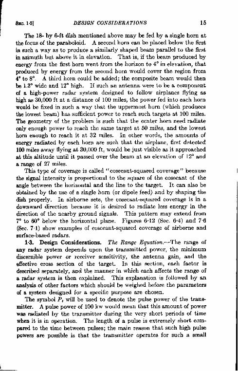
The 1S- by 6-ft dish mentioned above may be fed by a single horn atthe focus of the paraboloid. A second horn can be placed below the firstin such a way as to produce a similarly shaped beam parallel to the firstin azimuth but above it in elevation. That is, if the beam produced byenergy from the first horn went from the horizon to 4° in elevation, thatproduced by energy from the second horn would cover the region from4° to 8°. A third horn could be added; the composite beam would thenbe 1.3° wide and 12” high. If such an antenna were to be a componentof a high-power radar system designed to follow airplanes flying ashigh as 30,000 ft at a distance of 100 miles, the power fed into each hornwould be fixed in such a way that the uppermost horn (which producesthe lowest beam) has sufficient power to reach such targets at 100 miles.The geometry of the problem is such that the center horn need radiateonly enough power to reach the same target at 50 miles, and the lowesthorn enough to reach it at 32 miles. In other words, the amounts ofenergy radiated by each horn are such that the airplane, first detected100 miles away flying at 30,000 ft, would be just visible as it approachedat this altitude until it passed over the beam at an elevation of 12° anda range of 27 miles.
This type of coverage is called “ cosecant-squared coverage” becausethe signal intensity is proportional to the square of the cosecant of theangle between the horizontal and the line to the target. It can also beobtained by the use of a single horn (or dipole feed) and by shaping thedish properly. In airborne sets, the cosecant-squared coverage is in adownward direction because it is desired to radiate less energy in thedirection of the nearby ground signals. This pattern may extend from7° to 60° below the horizontal plane. Figures 6“12 (Sec. 6“4) and 7“6(Sec. 7“1) show examples of cosecant-squared coverage of airborne andsurface-based radars.
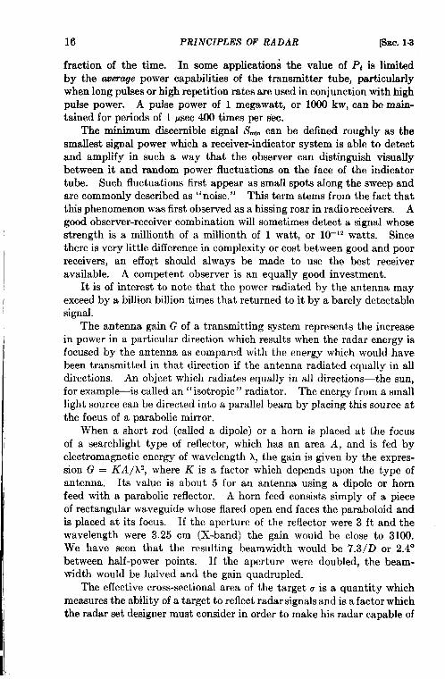
1.3. Design Considerations. The RaWe Equation.—The range ofany radar system depends upon the transmitted power, the minimumdiscernible power or receiver sensitivity, the antenna gain, and theeffective cross section of the target. In this section, each factor isdescribed separately, and the manner in which each affects the range ofa radar system is then explained. This explanation is followed by ananalysis of other factors which should be weighed before the parametersof a system designed for a specific purpose are chosen.
The symbol P, will be used to denote the pulse power of the trans-mitter. A pulse power of 100 kw would mean that this amount of powerwas radiated by the transmitter during the very short periods of timewhen it is in operation. The length of a pulse is extremely short com-pared to the time between pulses; the main reason that such high pulsepowers are possible is that the transmitter operates for such a small
16 PRINCIPLES OF RADAR [SEC. 1.3
fraction of the time. In some applications the value of P, is limitedby the averoge power capabilities of the transmitter tube, particularlywhen long pulses or high repetition rates are used in conjunction with highpulse power. A pulse power of 1 megawatt, or 1000 kw, can be main-tained for periods of 1 psec 400 times per sec.
The minimum discernible signal Sti can be defined roughly as thesmallest signal power which a receiver-indicator system is able to detectand amplify in such a way that the observer can distinguish visuallybetween it and random power fluctuations on the face of the indicatortube. Such fluctuations first appear as small spots along the sweep andare commonly described as “noise.” This term stems from the fact thatthis phenomenon was first observed as a hissing roar in radio receivers. Agood observer-receiver combination will sometimes detect a signal whosestrength is a millionth of a millionth of 1 watt, or 10–12 watts. Sincethere is very little difference in complexity or cost between good and poorreceivers, an effo@ should always be made to use the best receiveravailable. A competent observer is an equally good investment.
It is of interest to note that the power radiated by the antenna mayexceed by a billion billion times that returned to it by a barely detectablesignal.
The antenna gain G of a transmitting system represents the increasein power in a particular direction which results when the radar energy isfocused by the antenna as compared with the energy which would havebeen transmitted in that direction if the antenna radiated equally in alldirections. An object which radiates equally in all directions—the sun,for example-is called an “isotropic” radiator. The energy from a smalllight source can be directed into a parallel beam by placing this source atthe focus of a parabolic mirror.
When a short rod (called a dipole) or a horn is placed at the focusof a searchlight type of reflector, which has an area A, and is fed byelectromagnetic energy of wavelength A, the gain is given by the expres-sion G = KA/A2, where K is a factor which depends upon the type ofantenna. Its value is about 5 for an antenna using a dipole or hornfeed with a parabolic reflector. A horn feed consists simply of a pieceof rectangular waveguide whose flared open end faces the paraboloid andis placed at its focus. If the aperture of the reflector were 3 ft and thewavelength were 3.25 cm (X-band) the gain would be close to 3100.We have seen that the resulting beamwidth would be 7.3/D or 2.4°between half-power points. If the aperture were doubled, the beam-width would be halved and the gain quadrupled.
The effective cross-sectional area of the target u is a quantity whichmeasures the ability of a target to reflect radar signals and is a factor whichthe radar set designer must consider in order to make his radar capable of
SFic.1.3] DESIGN CONSIDERATIONS 17
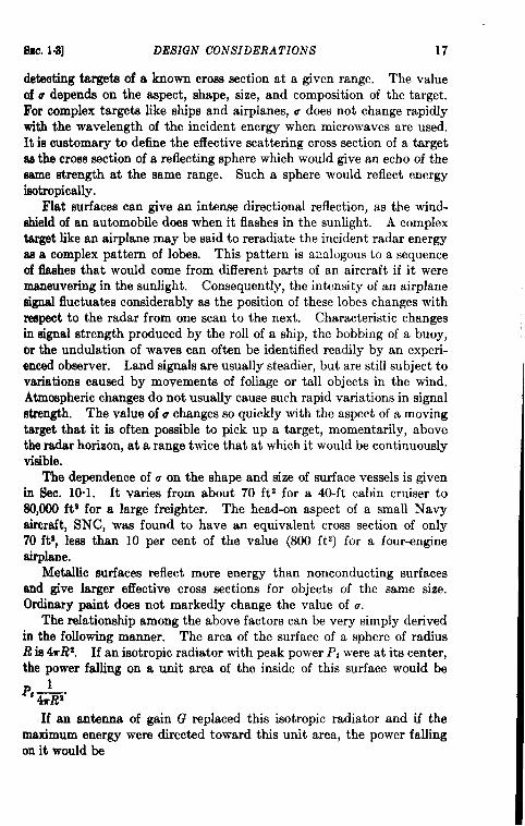
detecting targetiof aknowncross sectional a given range. The valueofu depends on the aspect, shape, size, and composition of the target.Forcomplex targets like ships and airplanes, udoes not change rapidlywith the wavelength of the incident energy when microwaves are used.It is customary to define the effective scattering cross section of a targetas the cross section of a reflecting sphere which would give an echo of thesame strength at the same range. Such a sphere would reflect energyisotropically.
Flat surfaces can give an intense directional reflection, as the wind-shield of an automobile does when it flashes in the sunlight. A complextarget like an airplane maybe said to reradiate the incident radar energyss a complex pattern of lobes. This pattern is analogous to a sequenceof flashes tha~ would come from different parts of an aircraft if it weremaneuvering in the sunlight. Consequently, the intensity of an airplanesignal fluctuates considerably as the position of these lobes changes withrespect to the radar from one scan to the next. Characteristic changesin signal strength produced by the roll of a ship, the bobbing of a buoy,or the undulation of waves can often be identified readily by an experi-enced observer. Land signals are usually steadier, but are still subject tovariations caused by movements of foliage or tall objects in the wind.Atmospheric changes do not usually cause such rapid variations in signalstrength. The value of u changes so quickly with the aspect of a movingtarget that it is often possible to pick up a target, momentarily, abovethe radar horizon, at a range twice that at which it would be continuouslyvisible.
The dependence of u on the shape and size of surface vessels is givenin Sec. 10.1. It varies from about 70 ft ~ for a 40-ft cabin cruiser to80,000 ft~ for a large freighter. The head-on aspect of a small Navyaircraft, SNC, was found to have an equivalent cross section of only70 ft?, less than 10 per cent of the value (800 ftz) for a four-engineairplane,
Metallic surfaces reflect more energy than nonconducting surfacesand give larger effective cross sections for objects of the same size.ordinary paint does not markedly change the value of a.
The relationship among the above factors can be very simply derivedin the following manner. The area of the surface of a sphere of radiusR is 4mR2, If an isotropic radiator with peak power P, were at its center,the power falling on a unit area of the inside of this surface would be
P, --L&R%
If an antenna of gain G replaced this isotropic radiator and if themaximum energy were directed toward this unit area, the power fallingon it would be
18 PRINCIPLES QF RADAR
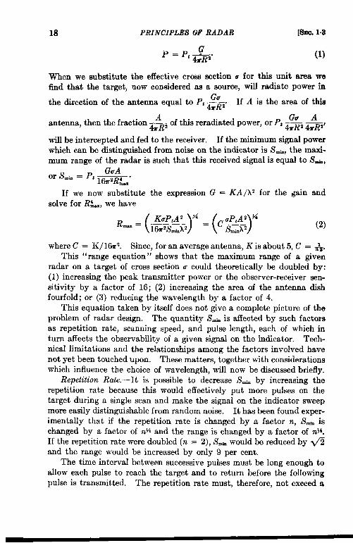
p . pt -.&.
When we substitute the effective cross section o
[sm. 1.3
(1)
for this unit area wefind that the target, now considered as a source, will radiate power in
the direction of the antenna equal to P, $. If A is the area of this
Aantenna, then the fraction —
Gv A&R2 of this reradiated power, or Pt ————&R2 &R2’
will be intercepted and fed to the receiver. If the minimum signal powerwhich can be distinguished from noise on the indicator is S~, the maxi-mum range of the radar is such that this received signal is equal to Sti,
GuAor Smb=Pt —.
l&rZR~
If we now substitute the expression G = KA/h2 for the gain andsolve for R~, we have
(2)
where C = K/l&rz. Since, for an average antenna, K is about 5, C = ~.This “range equation” shows that the maximum range of a given
radar on a target of cross section u could theoretically be doubled by:(1) increasing the peak transmitter power or the observer-receiver sen-sitivityy by a factor of 16; (2) increasing the area of the antenna dishfourfold; or (3) reducing the wavelength by a factor of 4.
This equation taken by itself does not give a complete picture of theproblem of radar design. The quantity S~h is affected by such factorsas repetition rate, scanning speed, and pulse length, each of which inturn affects the observability of a given signal on the indicator. Tech-nical limitations and the relationships among the factors involved havenot yet been touched upon. These matters, together with considerationswhich influence the choice of wavelength, will now be discussed briefly.
Repetition Rate.—It is possible to decrease Sti by increasing therepetition rate because this would effectively put more pulses on thetarget during a single scan and make the signal on the indicator sweepmore easily distinguishable from random noise. It has been found exper-imentally that if the repetition rate is changed by a factor n, S’* ischanged by a factor of n% and the range is changed by a factor of n}i.If the repetition rate were doubled (n = 2), S- would be reduced by @and the range would be increased by only 9 per cent.
The time interval between successive pulses must be long enough toallow each pulse to reach the target and to return before the followingpulse is transmitted. The repetition rate must, therefore, not exceed a

SEC.1.3] DESIGN CONSIDERATIONS 19
value compatible with the maximum range of the set. The averagepower of the transmitter tube depends directly on how often it is requiredto send out pulses. Its power capabilities often limit the repetition rate.
Because the range is improved and moving target indication (seeSec. 7.9) is more satisfactory, it is usually desirable, within the limitationsmentioned in the previous paragraph, to make the repetition rate as highas possible. There is a very wide range in the repetition rates used withdifferent radars; some operate at 60 and others at 4000 pulses per sec.
Scanning Losses. —Another consideration that enters into the value ofk’~bis that of scanning losses. 1 The range of a radar system when itsantenna is continuously scanning is not so great as it is when this antennais continuously pointed in the general direction of the target. This lattercondition is called ‘‘ searchlighting. ”
The detectability of a weak signal (expressed as S~,m)is affected bythe rate of scan for much the same reason that it is affected by the changesin the repetition rate. An experimental comparison between conditionsof scanning and searchlighting has shown that Smi. is proportional to(8/t)~, where t is the time in seconds during which pulses are strikingthe target on each scan. This relationship holds only for values of t lessthan 8 sec. If, for instance, the antenna rotates at 6 rpm, it scans 36° persec. If the beam is 6° wide, pulses effectively strike the target for + secper scan. Sti is then (48) )$ times as large as its value under search-lighting conditions and the loss in range is equal to (48)% = 1.62. Inother words, the range under searchlighting conditions is 1.62 timesgreater for a given target than if the antenna were rotating at 6 rpm.Thus it is evident that the ratio of beamwidth to scan rate governs theamount of scanning loss. To avoid excessive losses, a radar producinga narrow beam should be made to scan slowly.
Pulse Length.-Another factor which affects the range of a system isthe pulse length. The random background-noise power of a receivingsystem, PE, is directly proportional to its bandwidth and inversely pro-portional to the pulse length. Since S~ is proportional to P., it is alsoinversely proportional to the pulse length. If the pulse length weredoubled, the range would be increased by a factor of 2~~,or 19 per cent.
The limitations imposed by lengthening the pulse are: (1) the loss inminimum range detection and in range resolution; (2) an increase in thesignal return from clouds and ground clutter compared with the returnfrom sharply defined targets; (3) considerations of permissible averagetransmitted power. In order to maintain the same average power as thepulse is lengthened, it is customary to reduce the repetition rate. Thedisadvantages in doing this have been previously outlined.
1A completediscussionof scanninglossesis given in Radar System En@”nseri~,Vol. 1, RadiationLaboratoryS&es.
20 PRINCIPLES OF RADAR [SEC.1.3
A pulse length of 1 or 2 psec has been found to be a good compromisewhen reasonable range resolution and extreme ranges are required. Apulse length of+ or+ psec has been used to advantage in shipborne radarsystems where range resolution and minimum range are more importantthan the detection of targets at great distances. Radar systems whichcan transmit either short or long pulses have proven satisfactory.
A useful summary of these factors affecting the minimum observablesignal is given by the equation
is.=—[ 1angle of scan in 8 sec 94
(PyF) ~’ beamwidthP. (3)
The proportionality factor of 90 is an empirical constant that fits experi-mental data so that the approximate useful range of several representa-tive systems can be calculated from Eq. (2) when the above expressionis used for S~~.
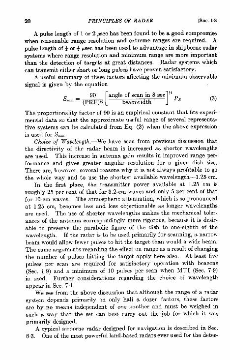
Choice of Wavelength.—We have seen from previous discussion thatthe directivity of the radar beam is increased as shorter wavelengthsare used. Thk increase in antenna gain results in improved range per-formance and gives greater angular resolution for a given dish size.There are, however, several reasons why it is not always profitable to gothe whole way and to use the shortest available wavelength-1.25 cm.
In the first place, the transmitter power available at 1.25 cm isroughly 25 per cent of that for 3.2-cm waves and only 5 per cent of thatfor 10-cm waves. The atmospheric attenuation, which is so pronouncedat 1.25 cm, becomes less and less objectionable as longer wavelengthsare used. The use of shorter wavelengths makes the mechanical toler-ances of the antenna correspondingly more rigorous, because it is desir-able to preserve the parabolic figure of the dish to one-eighth of thewavelength. If the radar is to be used primarily for scanning, a narrowbeam would allow fewer pulses to hit the target than would a wide beam.The same arguments regarding the effect on range as a result of changingthe number of pulses hitting the target apply here also. At least fivepulses per scan are required for satisfactory operation with beacons(Sec. 19) and a minimum of 10 pulses per scan when MTI (Sec. 7.9)is used. Further considerations regarding the choice of wavelengthappear in Sec. 7.1.
We see from the above discussion that although the range of a radarsystem depends primarily on only half a dozen factors, these factorsare by no means independent of one another and must be weighed insuch a way that the set can best carry out the job for which it wasprimarily designed.
A typical airborne radar designed for navigation is described in Sec.6.3. One of the most powerful land-based radars ever used for the detec-
Sac. 14] EARTH’S CUR VA TURE-A TMOSPHERIC REFRACTION 21
tion of aircraft in air surveillance problems is described briefly in Sec.7’1, and in considerable detail in Radar System Engineering, Vol. 1.
Although these two radars represent extremes in radar design, the argu-ments used have a certain degree of similarity and general application.A radar proposed for shipborne navigation is described in Chap. 10.
Experience has shown that for surface-based radars to be used foraircraft detection, which, therefore, require higher power and cose-cant-squared antenna beams, a wavelength between 8 and 25 cm shouldbe used. (A detailed analysis of this question is given in Sec. 7-1.) Inthe case of an airborne system in which weight and space are at a premium,small dishes and a wavelength either slightly longer or shorter than 1.25cm would seem desirable. A shipborne navigational radar system canusually use moderate-sized dishes. Since the purpose of a shipbornesystem is to detect and locate the positions of surface vessels, icebergs,lighthouses, land surfaces, and buoys, a wavelength just enough longerthan 1.25 cm to avoid atmospheric absorption and to permit the bestpossible low coverage near the horizon for a given antenna height wouldbe most useful. Radio waves between 1 and 12 cm long are often called“microwaves.” High resolution in both range and azimuth is requiredif the radar is to be used for pilotage purposes in narrow waters or indocking operations. Consequently, dishes as large as permissible, shortwavelengths, and short pulses are desirable features of a shipborne radarsystem.
PROPAGATION
1.4. Curvature of the Earth and Atmospheric Refraction. I—If weneglect the effects of the atmosphere, microwave radiation travels instraight lines; the curvature of the earth is an ultimate limitation on therange of any radar set. In practice, it is found that horizontal stratifi-cation of the atmosphere of the earth causes refraction of the microwaverays, usually bending them downward so that they tend to follow moreclosely the surface of the earth.
The effects of atmospheric refraction are usually unimportant forairborne radar sets because the wave path traverses the stratified layersat such large angles that refraction effects are not noticeable. In addi-tion, the horizon is at such a great distance from high-flying aircraft thatthe limitation is in the radar set itself. For surface-based radars,however, for which the range limit is usually the horizon, refraction isimportant.
If a radar antenna is at height ha above the surface of the earth, thegeometrical distance to the horizon, assuming the radius of the earth tobe 4000 statute miles, is given by the relation D = 1.08 fi, where hais in feet and D is in nautical miles. The geometrical distance to the
1By J. P. Nash.
22 PRINCIPLES OF RADAR [i3Ec. 1.5
hotizon from a height of 100 ft is then 10.8 nautical miles. If there is asmall target at height h; above the surface, the total horizon range is thesum of the distances to the horizon from both transmitter and target,or D = 1.08. (fit + fi). For microwave radar energy, which isrefracted more than light by the atmosphere, the factor becomes about1.24.
If the formula D = 1.24 fi is used to calculate radar-horizondistances, the result is the same as if rectilinear propagation were assumedon an earth with a radius ~ the true radius of the earth. This is a con-venient concept which makes it possible without loss of accuracy to drawdiagrams with rays as straight lines rather than curved ones; the notionof a radar earth is universally used for such purposes. However, there isnothing hard and fast about the choice of ~ as a conversion factor; itrepresents an average from many meteorological observations over a widerange of climatic conditions. Similar results are obtained when\ is used.
The # value is based upon the assumption of “standard” refraction,which is defined as that resulting from a linear decrease in the refractiveindex of the atmosphere with height at a rate of approximately 1.2 x 10_sper ft. Nonstandard propagation is briefly discussed in Sec. 10.1.
1.6. Atmospheric Attenuation. ]-The atmospheric attenuation ofmicrowave radiation varies with frequency. It can be generally statedthat although the effects are not serious at 3 and 10 cm, they are at 1.25cm. We now discuss in turn attenuation by water present as rain,water present as clouds, and water present as vapor. Attenuation bynitrogen and oxygen and other components of the atmosphere is notusually important in these three bands. For wavelengths somewhatshorter than 1.25 cm, however, oxygen attenuation does become verylarge.
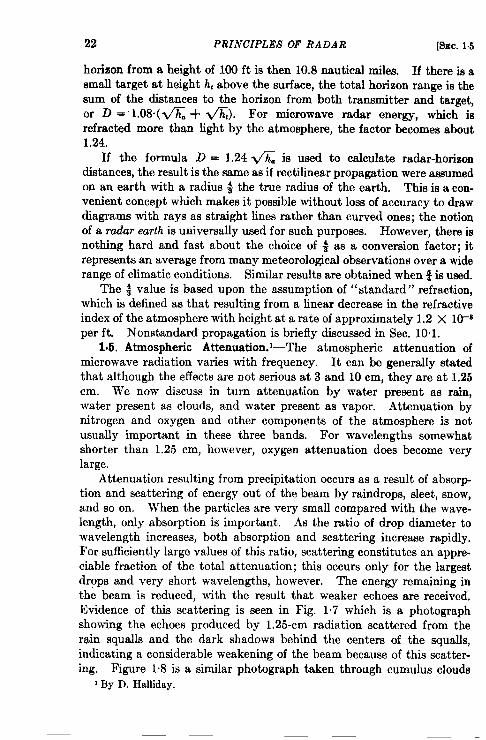
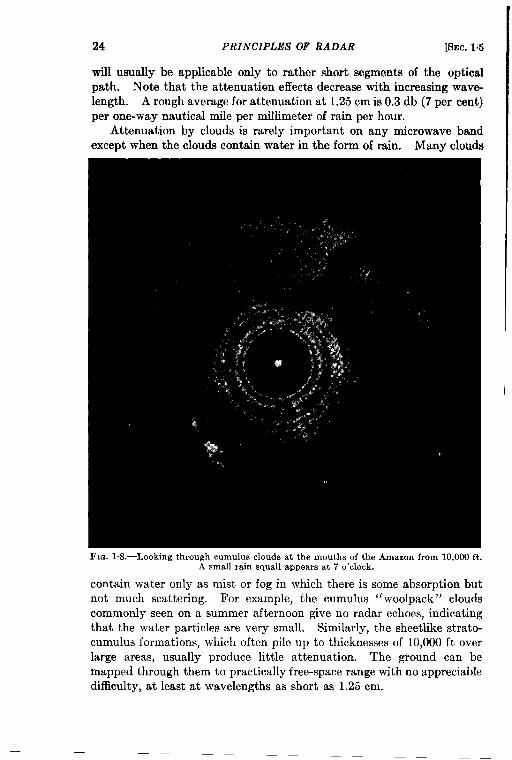
Attenuation resulting from precipitation occurs as a result of absorption and scattering of energy out of the beam by raindrops, sleet, snow,and so on. When the particles are very small compared with the wave-length, only absorption is important. As the ratio of drop diameter towavelength increases, both absorption and scattering increase rapidly.For sufficiently large values of this ratio, scattering constitutes an appre-ciable fraction of the total attenuation; thk occurs only for the largestdrops and very short wavelengths, however. The energy remaining inthe beam is reduced, with the result that weaker echoes are received.Evidence of this scattering is seen in Fig. 1.7 which is a photographshowing the echoes produced by 1.25-cm radiation scattered from therain squalls and the dark shadows behind the centers of the squalls,indicating a considerable weakening of the beam because of this scatteri-ng. Figure 1.8 is a similar photograph taken through cumulus clouds
I By D. Halliday.
24 PRINCIPLES OF RADAR [SEC. 1.5
will usually be applicable only to rather short segments of the opticalpath. Note that the attenuation effects decrease with increasing wave-length. A rough average for attenuation at 1.25 cm is 0.3 db (7 per cent)per one-way nautical mile per millimeter of rain per hour.
Attenuation by clouds is rarely important on any microwave bandexcept when the clouds contain water in the form of rain. Many clouds
FIG. I.S.—Looking through cumulus clouds at the mouths of the Amazon from 10,000 ft.A small rain squall appears at 7 o’clock.
contain water only as mist or fog in which there is some absorption butnot much scattering. For example, the cumulus “ woolpack” cloudscommonly seen on a summer afternoon give no radar echoes, indicatingthat the water particles are very small. Similarly, the sheetlike strato-cumulus formations, which often pile up to thicknesses of 10,000 ft overlarge areas, usually produce little attenuation. The ground can bemapped through them to practically free-space range with no appreciabledifficult y, at least at wavelengths as short as 1.25 cm.
SEC. 1.5] ATMOSPHERIC ATTENUATION 25
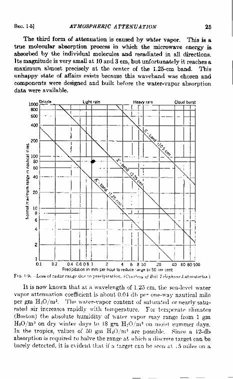
The third form of attenuation is caused by water vapor. This is atrue molecular absorption process in which the microwave energy isabsorbed by the individual molecules and reradiated in all directions.Its magnitude is very small at 10 and 3 cm, but unfortunately it reaches amaximum almost precisely at the center of the 1.25-cm band. Thisunhappy state of affairs exists because this waveband was chosen andcomponents were designed and built before the water-vapor absorptiondata were available.
1000Soo60U
400
200;.-E~ 100S 80260c.-; 40sE~ 20.-x?~ 10z s‘6
4
2
10.1 0.2 0.4060S1 2 4 6S10 20 40 6080100
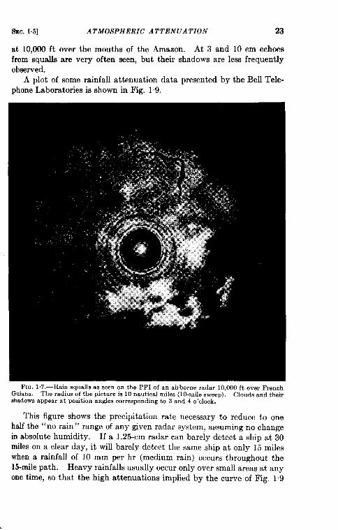
FJG.PreclpitahonInmm per hourto reduce rangeto 50 per cent
1.9.—Loss of radar range due to precipitation. (Couricsyof Bdl Tdephom Laborator iea.)
It is now known that at a wavelength of 1,25 cm, the sea-level watervapor attenuation coefficient is about 0,04 db per one-way nautical mileper gm HZO/m3. The water-vapor content of saturated or nearly satu-rated air increases rapidly with temperature. For temperate climates(Boston) the absolute humidity of \vater vapor may range from 1 gmH20/m3 on dry winter days to 18 gm H*O/ma on moist summer days.In the tropics, values of 50 gm H*O,ms are possible, Since a 12-dbabsorption is required to halve the range at which a discrete target can bebarely detected, it is evident that if a target can be seen at 1,5miles on a
26 PRINCIPLES OF RADAR [SEC.1.6
day when the absolute humidity is 10 gm H20/m3 it could be seen at 30miles on a perfectly dry day.
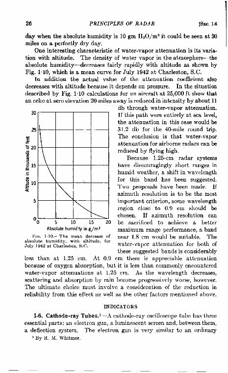
One interesting characteristic of water-vapor attenuation is its varia-tion with altitude. The density of water vapor in the atmosphere-theabsolute humidity-decreases fairly rapidly with altitude as shown byFig. 1.10, which is a mean curve for July 1942 at Charleston, S.C.
In addition the actual value of the attenuation coe5cient alsodecreases with altitude because it depends on pressure. In the situationdescribed by Fig. 1.10 calculations for an aircraft at 25,000 ft show thatan echo at zero elevation 20 miles away is reduced in intensit y by about 11
Absolute humidity in g/ma
FIG. l.10,—The mean decrease ofabsolute humidity, with altitude, forJuly 1942 at Charleston, S.C.
less than at 1.25 cm. At 0.9
db through water-vapor attenuation.If this path were entirely at sea level,the attenuation in this case would be31.2 db for the 40-mile round trip.The conclusion is that water-vaporattenuation for airborne radars can bereduced by flying high.
Because 1.25-cm radar systemshave discouragingly short ranges inhumid weather, a shift in wavelengthfor this band has been suggested.Two proposals have been made. Ifazimuth resolution is to be the mostimportant criterion, some wavelengthregion close to 0.9 cm should bechosen. If azimuth resolution canbe sacrificed to achieve a bettermaximum range performance, a bandnear 1.8 cm would be suitable. Thewater-vapor attenuation for both ofthese suggested bands is considerably
cm there is appreciable attenuationbecause of oxygen absorption, but it is less than ~ommonly encounteredwater-vapor attenuations at 1.25 cm. As the wavelength decreases,scattering and absorption by rain become progressively worse, however.The ultimate choice must involve a consideration of the reduction inreliability from this effect as well as the other factors mentioned above.
INDICATORS
1.6. Cathode-ray Tubes.1—A cathode-ray oscilloscope tube has threeessential parts: an electron gun, a luminescent screen and, between them,a deflection system. The electron gun is very similar to an ordinary
1By R. M. Whitmer.
SEC.16] CATHODE-RAY TUBEAS 27
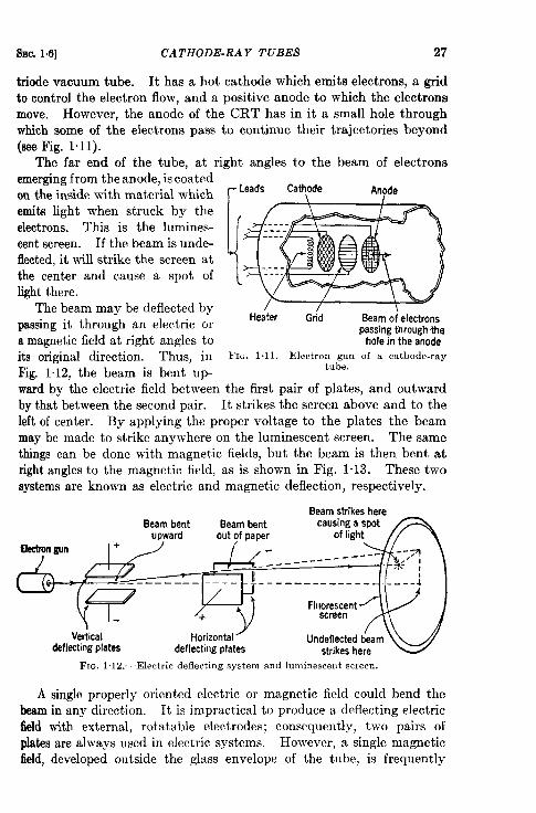
triode vacuum tube. Ithas a hot cathode which emits electrons, a gridtocontrol the electron flow, andapositive anode to which the electronsmove. However, the anode of the CRT has in it a small hole throughwhich some of the electrons pass to continue their trajectories beyond(see Fig. 1.11).
The far end of the tube, at right angles to the beam of electronsemerging from the anode, is coatedon the inside with material whicheraits light when struck by theelectrons. This is the lumines-cent screen. If the beam is unde-fiected, it will strike the screen atthe center and cause a spot oflight there.
The beam may be deflected bypassing it through an electric ora magnetic field at right angles to
Heater Grid Beam of electronspassing through the
hole in the anode
its original direction. Thus, in FIG. 1.1I.—Electron gun of a cathode-ray
Fig. 1.12, the beam is bent up-tube.
ward by the electric field between the first pair of plates, and outwardby that between the second pair. It strikes the screen above and to theleft of center. By applying the proper voltage to the plates the beammay be made to strike anywhere on the luminescent screen. The samethings can be done with magnetic fields, but the beam is then bent atright angles to the magnetic field, as is shown in Fig. 1”13. These twosystems are known as electric and magnetic deflection, respectively.
BeamstrikeshereBeam bent Beam bent causing a spot
upward
Qectrongun +
Vertical Horizontaldeflecting plates deflecting plates strikes here
Fm. 1.12.—Electric deflecting system and Imninescent screen.
A single properly oriented electric or magnetic field could bend thebeam in any direction. It is impractical to produce a deflecting electricfield with external, rotatable electrodes; consequently, two pairs ofplates are always used in electric systems. However, a single magneticfield, developed outside the glass envelope of the tube, is frequently
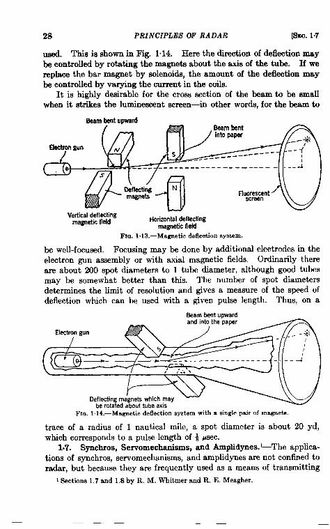
28 PRINCIPLES OF RADAR [SS9C.1.7
UA. This is shown in Fig. 1.14. Here the direction of deflection maybe controlled by rotating the magnets about the axis of the tube. If wereplace the bar magnet by solenoids, the amount of the deflection maybe controlled by varying the current in the coils.
It is highly desirable for the cross section of the beam to be smallwhen it strikes the luminescent screen-in other worda, for the beam to
&aambentwward
Uectrongun
L
(/
al
f-wkting Nmagnets flug;orcnt
‘L)Vettical ‘-’’ --’--
magntim 1WWmagnetic field -
(Li?i?--------J ----- ------- ------ ------ ----- d
aenecung-.:_ n-,- Horizontal deflecting
l%. 1.13.—Magnetic deflection system.
electrodes in theOrdinarily there
be well-focused. Focusing may be done by additionalelectron gun assembly or with axial magnetic fields.are about 200 spot diameters to 1 tube diameter, although good tubesmay be somewhat better than this. The number of spot diametersdetermines the limit of resolution and gives a measure of the speed ofdeflection which can be. used with a given pulse length. Thus, on a
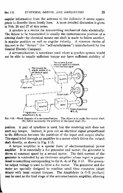
Beam bent uoward
\— I
.,,- q,
/
,“ n’?..”.
be rotated about tube axisDeflecting ma’gnets which may ~ -~
FKG.1.14.—Magnetic deflection system with a single pair of magnets.
trace of a radius of 1 nautical mile, a spot diameter is about 20 yd,which corresponds to a pulse length of ~ Ysec.
1.7. Synchros, Servomechanisms, and Amplidynes.1-The applica-tions of synchros, servomechanisms, and amplidynes are not confined toradar, but because they are frequently used as a means of transmitting
1 Sections1.7 and 1.8by R. M. Whitmerand R. E. Meagher.
SEC.1.7] SYNCHROS, SERVOS, AND AMPLID YNES 29
angular information from the antenna to the indicator it seems appro-priate to describe them briefly here. A more detailed discussion is given
in Vols. 26 and 27 of this series.A synchro is a device for transmitting mechanical data electrically.
The datum to be transmitted is usually the instantaneous position of arotating shaft—by electrical means one shaft is made to follow another,in angular position as well as angular velocity. A common device ofthis sort is the ‘‘ Selsyn” (for “self-synchronous”) manufactured by theGeneral Electric Company.
A servomechanism is sometimes used where a synchro system wouldnot be able to supply sufficient torque nor have sufficient stability of
Thmconverts82to an
proportionalto 0, -Oz
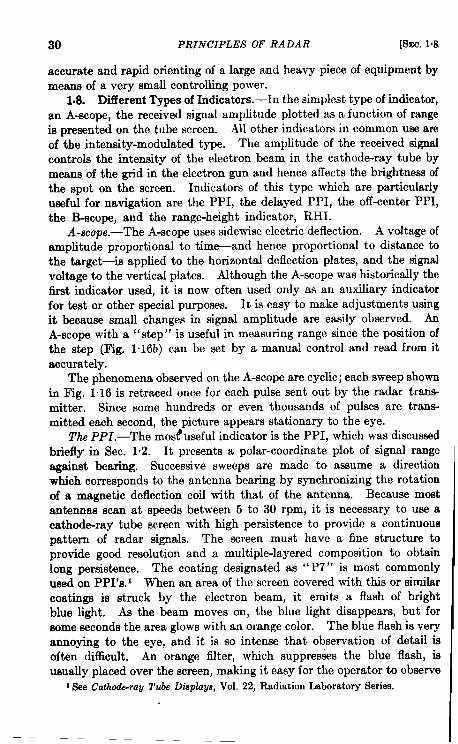
Fai.1.15.—Block diagram of a servomechanism. The object is to make the output shaft(OJ follow accurately the position of the input shaft (0,).
position. A pair of synchros is used, but the receiving unit does notexert any torque. Instead, it puts out an electrical signal proportionalti the difference between the positions of the input and output shafts.This signal is fed through an amplifier to a motor which drives the outputshaft directly, as shown in Fig. 1~15.
A torque amplifier is a special form of electromechanical poweramplifier. It is essentially a d-c generator and motor; the generator isdriven at constant speed by a second motor. The field current of thegenerator is controlled by an electronic amplifier whose input is propor-tional to something corresponding to the 191-o* of Fig. 1.15. The genera-tor output voltage is used to drive a d-c motor. The generator and d-cmotor are specially designed to combine small time constants (shortdelays) with large output torques. The Amplidyne (a G-E product)may be used as the final stage of the servomechanism amplifier, allowing
30 PRINCIPLES OF RADAR [SEC.I.&
accurate and rapid orienting of a large and heavy piece of equipment bymeans of a very small controlling power.
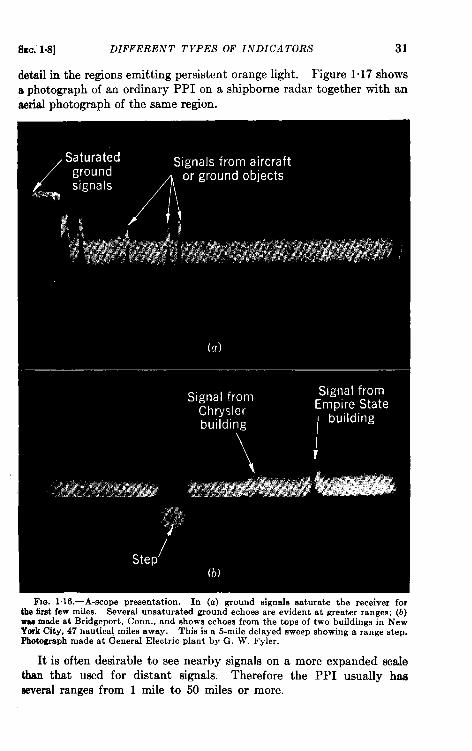
1.8. DiiYerent Types of Indicators.-In the simplest type of indicator,an A-scope, the received signal amplitude plotted as a function of rangeis presented on the tube screen. All other indicators in common use areof the intensity-modulated type. The amplitude of the received signalcontrols the intensity of the electron beam in the cathode-ray tube bymeans of the grid in the electron gun and hence affects the brightness ofthe spot on the screen. Indicators of this type which are particularlyuseful for navigation are the PPI, the delayed PPI, the off-center PPI,the B-scope, and the range-height indicator, RHI.
A-scope.—The A-scope uses sidewise electric deflection. A voltage ofamplitude proportional to time-and hence proportional to distance tothe target—is applied to the horizontal deflection plates, and the signalvoltage to the vertical plates. Although the A-scope was historically thefirst indicator used, it is now often used only as an auxiliary indicatorfor test or other special purposes. It is easy to make adjustments usingit because small changes in signal amplitude are easily observed. AnA-scope with a “step” is useful in measuring range since the position ofthe step (Fig. 1.16b) can be set by a manual control and read from itaccurately.
The phenomena obwxved on the A-scope are cyclic; each sweep shownin Fig. 1“16 is retraced once for each pulse sent out by the radar trans-mitter. Since some hundreds or even thousands of pulses are trans-mitted each second, the picture appears stationary to the eye.
The PP1.—The mosl?useful indicator is the PPI, which was discussedbriefly in Sec. 1.2. It presents a polar-coordinate plot of signal rangeagainst bearing. Successive sweeps are made to assume a directionwhich corresponds to the antenna bearing by synchronizing the rotationof a magnetic deflection coil with that of the antenna. Because mostantennas scan at speeds between 5 to 30 rpm, it is necessary to use acathode-ray tube screen with high persistence to provide a continuouspattern of radar signals. The screen must have a fine structure toprovide good resolution and a multiple-layered composition to obtainlong persistence. The coating designated as “ P7” is most commonlyused on PPI’s. 1 When an area of the screen covered with this or similarcoatings is struck by the electron beam, it emits a flash of brightblue light. As the beam moves on, the blue light disappears, but forsome seconds the area glows with an orange color. The blue flash is veryannoying to the eye, and it is so intense that observation of detail isoften difficult. An orange filter, which suppresses the blue flash, isusually placed over the screen, making it easy for the operator to observe
ISee Cathrk-ra~ Tube Dtipkwj Vol. 22, RadiationLaboratorySeries.
I
SEC.1.8] DIFFERENT TYPES OF INDICATORS 31
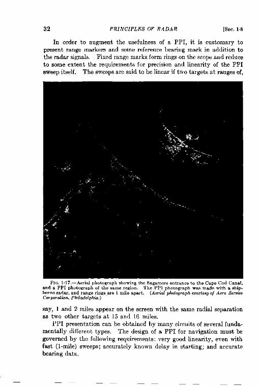
detail in the regions emitting persistent orange light. Figure 1~17 showsa photograph of an ordinary PPI on a shipborne radar together with anaerial photograph of the same region.
l%. 1.16.—A-scope presentation. In (a) ground signals saturate the receiver forthe 6rst few miles. Several unsaturated ground echoes are evident at greater ranges; (b)was made at Bridgeport, Corm., and shows echoes from the tops of two buildings in NewYork City, 47 nautical miles away. This is a 5-mile delayed sweep showing a range step.Photographmade at General Electric plant by G. W. Fyler.
It is often desirable to see nearby signals on a more expanded scalethan that used for distant signals. Therefore the PPI usually hasseveral ranges from 1 mile to 50 miles or more,
T~n:mp#ier Redmgular -wave ~ -mr cathode CumnfEenarator follmver L&me
+ 275 V —,. -.. . D ..,. ..- .,. 1..,.
I
3.75k 15k50W 5W
5FP71
Gateturnafi
I y’~–Xolulf Ilw
+C’ l&w04-.. I !47k
~–loov27k.5%22k-5%
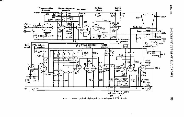
lW’ lW’FIG. 1.18.—A typical high-quality rotating-coil PPI circuit.
$+5000V
47 k--- 6COV----
~ 0,01Video
in~S& --- 470k5N7GT
51k 100k 33kIntensity
.
Focuscontrol6AG7
7
+150v
nN
Ocus
44< 51k5y.
70k.5z
ww
34 PRINCIPLES OF RADAR [SEC. t.8
There are three methods of generating the magnetic deflecting fieldsfor a PPI. In the first, known as MM (Magnetic-Mechanical) or rotatingcoil method, a single pair of deflecting coils (corresponding to the two barmagnets in Fig. 1014) is used. The variation of current through these coilsproduces the radial sweep of the electron beam. The coils are rotatedmechanically about the axis of the cathode-ray tube in synchronism withthe scanner rotation. Each of the other two methods uses two pairs offixed coils. The relative phases of the currents through them are suchthat they produce a resultant magnetic field which rotates about the axisof the tube. This is very similar to the rotating field in an inductionmotor. The currents may be applied directly, as in the MS (Magnetic-Selsyn) or resolved current method, or through a level-setting and ampli-
Antennaq
PPI coil
~--
ltol Igearratio
I I ICompass Ibearing 5 DG CT
(differential (controlgenerator) transformer)
Motor
synchroT
synchro
<I
To otherSewo
PPI’Sk amplifier
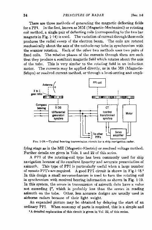
LFm. 1,19.—Typical bearing transmission circuit for a ship navigation radar.
fying stage as in the ME (Magnetic-Electric) or resolved voltage method.Further details are given in Vols. 1 and 22 of thk series.
A PPI of the rotating-coil type has been commonly used for shipnavigation because of its excellent linearity and accurate presentation ofazimuth. This type of PPI is particularly useful when a large numberof remote PPI’s are required. A good PPI circuit is shown in Fig. 1.18.1In this design a small servomechanism is used to turn the rotating coilin synchronism with received bearing information as shown in Fig. 1.19.In this system, the errors in transmission of azimuth data have a valuenot exceeding ~, which is probably less than the errors in readingazimuth on the tube. Other, less accurate designs are usually used inairborne radars because of their light weight.
Ars expanded picture may be obtained by delaying the start of anordinary PPI. When economy of parts is required, this is a simple and
1A detailedexplanationof this circuitk given in Vol. 22, of this series.
t?iEc. 1.8] DIFFERENT TYPES OF INDICATORS 35
effective way of obtaining expanded indication. The pattern is highlydistorted; for example, if a 25-mile delay be introduced, all targets at25 miles will appear superimposed at the center of the screen. Theeffect is similar to that which would be observed if a map were printedon a handkerchief whose center is placed over a hole formed by thethumb and forefinger of one hand, and part of the handkerchief drawnthrough the hole with the other hand.
A further modification of the PPI appears to be nearly ideal: thecenter of rotation of the PPI beam can be moved so that it is no longerthe geometrical center of the tube face. Indeed, if the center of rotationcould be moved anywhere and at the same time a wide range of sweep
57
16
11
6
1 1 1
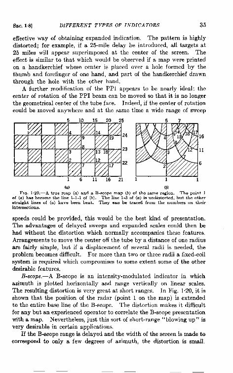
(a) (b)Fm. 1.20.—A true map (a) and a B-scope map (b) of the same region. The point 1
of (a) has become the line 1-1-1 of (b). The line 1-5 of (a) is undistorted, but the otherstraight lines of (a) have been bent. They ean be traced from the numbers on theirintersections.
speeds could be provided, this would be the best kind of presentation.The advantages of delayed sweeps and expanded scales could then behad without the distortion which normally accompanies these features.Arrangements to move the center off the tube by a distance of one radiusare fairly simple, but if a displacement of several radii is needed, theproblem becomes difficult. For more than two or three radii a fixed-coilsystem is required which compromises to some extent some of the otherdesirable features.
B-scope.—A B-scope is an intensity-modulated indicator in whichazimuth is plotted horizontally and range vertically on linear scales.The resulting distortion is very great at short ranges. In Fig. 1.20, it isshown that the position of the radar (point 1 on the map) is extendedto the entire base line of the B-scope. The distortion makes it difficultfor any but an experienced operator to correlate the B-scope presentationwith a map. Nevertheless, just thk sort of short-range “blowing up” isvery desirable in certain applications.
If the B-scope range is delayed and the width of the screen is made tocorrespond to only a few degrees of azimuth, the distortion is small.
36 PRINCIPLES OF RADAR [SEC. 1.9
Thk sort of presentation is very similar to the off-center PPI, but thecircuits for obtaining it are considerabley simpler. It is frequently used,therefore, to examine on a large scale a small part of the field which theradar covers.
RHI.—The range-height indicator, RHI, is used for the presentationof height data from systems that scan in a vertical plane. The indicatoris intensity-modulated, range is plotted horizontally, and height verti-cally. The scales are linear, but the height scale is more expanded thanthe range scale; for example, an inch measured vertically on the indicatorscreen may represent 10,000 ft in height, whereas an inch measured hori-zontally measures 10 miles. Typical RHI pictures are shown in Sec. 7.5.
RADAR BEACONS
13Y R. M. WHITMER AND J. B. PLATT
1.9. Operation.-A radar beacon, sometimes called a “transponder,”consists essentially of a receiver which picks up pulses from a radartransmitter, and a transmitter, triggered by the output of this receiver,which puts out signals to be detected by the radar receiver. The beaconmight be called a device for giving an amplified echo. When a radarcauses a beacon to operate it is said to be “interrogating” the beacon.
Because radar-to-beacon and beacon-to-radar transmissions are eachone-way, the signal intensities vary as the inverse square of the rangerather than as the inverse fourth power, as do ordinary radar echoes.This means that the range of a radar beacon maybe doubled by increasingthe radar transmitter power or the receiver sensitivity fourfold, whereas a16-fold increase would be required to double the range on ordinary echoes.Also, the power transmitted by the beacon is independent of the strengthof the interrogating signal. Hencej beacon signals maybe seen by radarsat much greater distances than may ordinary echoes. Usually therange is limited only by the horizon.
Distinctions between Echoes and Beacon Signals.—For most appli-cations in the microwave region, the frequency of the beacon transmitteris not the same as that of the radar transmitter. This means that theradar receiver must be retuned in order to receive the beacon. Other-wise, a second receiver must be used. In either case, normal echoes andbeacon signals may be presented separately. In addition, the microwavebeacon usually replies with a series of two to six pulses so spaced that theyappear to be 1 to 3 miles apart in range, all at the same azimuth, ratherthan with a single pulse for each pulse received. This distinctive group ofsignals cannot be mistaken for an echo from a normal target. Thespaces may be used to identify the beacon. The first of this series ofpulses reaches the radar receiver at very nearly the same instant as woulda normal echo from a target at the position of the beacon. On a scanning
SEC. 1.9] BEACONS 37
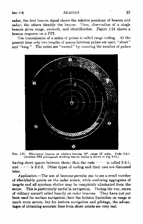
radar, the first beacon signal shows the relative positions of beacon andradar; the others identify the beacon. Thus, observation of a singlebeacon gives range, azimuth, and identification. Figure 1.21 shows abeacon response on a PPI.
The transmission of a series of pulses is called range coding. At thepresent time only two lengths of spaces between pulses are used, “short”and “long.” The codes are “named” by counting the number of pulses
FIG. 1.21 .—Microwave beacon at relative bearing 12”, range 27 miles. Code(Another PPI photograph showing beacon replies is shown in Fig. 61 1.)
3-2-1.
having short spaces between them; thus the code ““. .~ “ is called 3-2-1,and .. “O. . is 2-2-2. Other types of coding and their uses are dkcussedlater.
Application.-The use of beacons permits one to see a small numberof identifiable points on the radar sc~een, while confusing aggregates oftargets and all spurious clutter may be completely eliminated from thescope. This is particularly useful in navigation. During the war, crewsof military aircraft relied heavily on radar beacons. They have not yetbeen used for surface navigation; here the horizon limitation on range ismuch more severe, but for inshore navigation and pilotage, the advan-tages of obtaining accurate fixes from shore points are very real.
38 PRINCIPLES OF RADAR [SEC. 1.9
Beacons have also been installed in aircraft for use with airborne andground radar, for identification or increase in effective range or both.In the future they may also be used for limited communication.
During the war, many ground beacon stations were set up in theUnited States as well as abroad for use with airborne radars. Since theend of hostilities the United States Coast Guard has been made responsi-ble for their maintenance, just as in peacetime it is responsible for anumber of other types of navigational aids. Hydrographic Office Publi-cation No. 520 contains a list of beacon locations, operating hours, codes,
r+--Receivingantenna
1[
QDiscriminatorMust reject radar searchpulses but accept any
beacon interrogating pukes
*
TransmitterMagnetron to producepip-coded r-f power
of frequency assigned
TunerAllows frequencyto be set exactly
Coder ModulatorSpacing between successive Similar to radar
pips to be short or long modulatorchosen at will
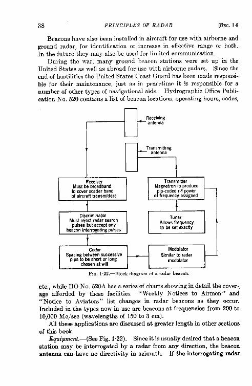
FIG. 1.22.—Block diagram of a radar beacon.
etc., while HO No. 520A has a series of charts showing in detail the cover--age afforded by these facilities. “Weekly Notices to Airmen” and“Notice to Aviators” list changes in radar beacons as they occur.Included in the types now in use are beacons at frequencies from 200 to10,000 Me/see (wavelengths of 150 to 3 cm).
All these applications are discussed at greater length in other sectionsof this book.
Equipment.-(See Fig. 1.22). Since it is usually desired that a beaconstation may be interrogated by a radar from any direction, the beaconantenna can have no directivity in azimuth. If the interrogating radar
SEC. 1.9] BEACONS 39
is at any appreciable distance from the beacon, the radar-to-beacon lineis very nearly horizontal. Conversely, when the radar-to-beacon line isnot approximately horizontal—as is the case when an aircraft is almostdirectly above a ground beacon—the range is very short. Hence, theantenna pattern must have a strong maximum in the horizontal direc-tion but it does not need high gain at high angles. Because of thisomnidirectionality in azimuth, the gain of a beacon antenna is muchsmaller than that of a radar antenna. Separate but identical transmittingand receiving antennas have been used, but TR switches satisfactory forbeacons are now available so that a common antenna is practicable.
In the microwave region it is neither practical nor desirable to adjusteach radar transmitter to exactly the same frequency, yet a beacon mustbe able to receive signals from any of them. In practice this has meantthat a beacon receiver designed for a certain nominal frequency wasrequired to cover a frequency band that might be 1 or 2 per cent wide,which at microwave frequencies may mean as much as 100 Me/see.This is called the scatter band because the frequencies of the differentradar transmitters are scattered throughout it. The sensitivity of such areceiver cannot be made greater than from 1 to 10 per cent of that of aradar receiver for the same nominal frequency, but because it is used onlywith one-way transmission this low sensitivity and the small antennagain do not usually limit the useful range from interrogator to beacon.
If many radars are within interrogation range and the beacon isoperated by each pulse that it receives, the resulting demands on thebeacon transmitter may well be excessive. This could happen eventhough none of the radars were deliberately interrogating the beacon.In order to reduce these demands, some sort of interrogation coding isfrequently used. In the simplest and commonest form, the beacon is sodesigned that it will not reply to a normal radar search pulse, but only toa pulse of a certain specified length. Since the beacon does not replyuntil the length of the received pulse has been “measured,” a small delayin range is introduced; the delay amounts only to about 300 yd, andcompensation may be made for it in the radar sweep circuits. The unitin the beacon that measures the length of the received pulse is called thediscriminator. In some specialized applications, discriminators are notused.
If two radars are interrogating the same beacon and both scanners arepointed toward it, each operator will see the beacon’s replies to the other.These are easily interpreted as false signals because they are unsynchron-ized; that is, since the pulse recurrence rates are never exactly equal fordifferent radars, the “false” signals appear at a different range on eachscan, while the “true” beacon replies always appear at the same range.But if a large number of radars interrogate the same beacon simultane-
40 PRINCIPLES OF RADAR [SEC. 1.9
ously, each will see so many false signals that it may be difficult to tindthe true ones. This was observed on airborne radars when they wereinterrogating beacons near airfields. Interrogation codhg prevents thiscondition from arising often.
Beacon Transmittw Frequency. -In order that all radars operating ina given frequency band can receive all beacons at will, an assignment of aspot frequency for the beacon transmission is made; both the beacontransmitters and the radar receivers must be accurately tuned to it.Standard cavities, which pass energy of only one frequency, are used forreference, just as quartz crystals are used at lower frequencies. Thefrequency chosen is a little outside the scatter band to avoid interferencewith the echoes of any radar set. Because of the one-way transmission,the required transmitter power is appreciably smaller than that of a radartransmitter.
Special Provisions in the Radar.—At the radar set, it is necessaryto alter the pulse length and to retune the receiver in order to interrogateand receive the beacon. Usually the pulse-repetition frequency ischanged, also, to keep the average power output constant. These opera-tions are all performed by throwing a single switch from “search”position to “beacon” position. If the radar set does not have automaticfrequency control some manual tuning will also be necessary. In eithercase a standard cavity is used as a frequency reference.
In the radar-plus-beacon system we have two distinct transmission-reception links. The maximum range on the interrogation (radar-to-beacon) link is determined by one set of factors, while the response range(beacon-to-radar) is limited by another set. It is desirable for these tworange limits to be equal. This is accomplished easily if all the radarsdesigned to operate with a given group of beacons are identical, butdifferences among the radars may affect the two range limits differently,For example, consider two which are identical except for transmitterpower. The radar having the greater power can interrogate the beacon
, at a greater range, but the range limits for receiving the beacon are thesame for both radars.
Future Developments; Coding.—The simple range-coding system men-tioned above is the only one which has been used for microwave beaconsin the past, and it is the only practical one which can be “read” directlyfrom the radar indicator. The total number of distinct codes which thissystem gives is about 50, if the number of pulses does not exceed six.This is sufficient for identification of ground and shore navigationalbeacons because codes may be repeated without confusion with sufficientgeographical separation.
For other applications, more codes are needed. The electronic tech-niques which would be used for more elaborate coding and decoding are
SEC. 1.10] FUTURE DEVELOPMENTS; SYSTEMS 41
already well developed, but since they have not been put to this particularuse only rough estimates of relative complexity and weight can be given.Among these systems are:
1. Space-coding. This is an obvious generalization of range-coding.Instead of allowing only short and long spaces between beaconreply pulses, the spaces may be varied in steps of, say, 1 psec.If only three pips, with spaces of from 1 to 10 ysec, are used, 100codes are available. Using six pips, this number is increased to100,000. The coder would be very similar to those now in use,but the tolerances on components and voltages would be muchcloser. Adecoder would berequired in the radar.
2. Pulse-width Coding. In this system, the spacing between pulsesis kept constant, but the width of each pulse in a reply series maybevaried. The range of practical pulse width is less than that of thespaces; probably 1, 2, and 3 psec would be used. Four pips heregive 81 codes and six give 729. The coder and modulator in thebeacon would be heavier and more complex than those now in use,but not seriously so. It would again be necessary to use a decoderin the radar. All such proposed systems meet with difficulties iftwo or more beacons are likely to be situated so that their repliesoverlap each other, as might happen if they were carried in aircraftflying close together.
Other systems, such as frequency-coding (the beacon replying ontwo or more radio frequencies simultaneously), and time- or gap-coding(in which the beacon is insensitive for periods as long as seconds), havebeen conceived, and gap-coding has been used but it is out of the questionwith scanning radar sets.
Combinations of space- and width-coding may be used to give enor-mous numbers of distinct codes. For instance, if three pips, each 1, 2, or3 psec long are used, with spaces variable from 5 to 25 psec in steps of 1~sec, we have 10,800 codes. The total is increased to 648,000 if fourpips are used.
Such systems probably will be most practical for ground or shoreradar sets working with airborne or shipborne beacons. Fortunately,these are just the applications in which a large number of codes are neededfor identification.
1.10. Future Developments; Systems.—The description given hereapplies to microwave radar beacons as they were used during the war.Three narrow and widely separated frequency bands were used for air-borne radar, and beacons were designed for two of these bands—thescatter bands mentioned above. In order to give navigational service
42 PRINCIPLES OF RADAR [SEC. 1.10
to all airborne microwave radars, each ground beacon station wasrequired to have distinct beacon equipment for each of the two bands.
Actually, a far greater number of beacons operating outside themicrowave region (in the neighborhood of 200 Me/see) were used,because they were developed earlier. Their use was somewhat differentand suggests a different approach to the beacon problem.
Most of these low-frequency beacons were used in the IFF system(Identification, Friend or Foe). The objective was to equip everyfriendly ship and aircraft with a beacon whose reply would establish thefriendly character of the vessel or airplane. Obviously, because allbeacons of this system had to be alike to be of any use, it was necessaryto supply extra interrogating equipment to operate in conjunction withthe great variety of radar sets at different frequencies. In a similar way,the British developed such supplementary equipment to enable aircraftcarrying radars which operated at many different frequencies to interr~gate beacons in the 200-Mc/sec region.
Some problems can be solved entirely by the use of beacons andinterrogating equipment which does not display radar echoes at all.Such an apparatus is called an ‘‘ interrogator-responsor. ” This equip-ment can be made somewhat simpler than a true radar set, especially ifonly range or relatively inaccurate determination of azimuth will suffice.
The designer of a navigational system should, therefore, considerthese three combinations of equipment:
1. Beacons with simple interrogator-responsors that are not completeradar sets.
2. Separate-band beacons which are in a special frequency band setaside for the purpose, with supplementary interrogating andreceiving equipment added to the radar sets.
3. Beacons to operate directly with the radar sets at the radarfrequencies.
If the designer concludes that it is not necessary or desirable toplan for the radar use, he should be quite clear as to why not. Theextra complication required to achieve radar performance would seem tobe small compared to the probable value of the radar information.
If the primary function is to be the radar use, but beacons are alsodesired, the problem is to decide between the use of separate-bandbeacons and radar beacons. There seems to be no obvious solutionthat is best for all cases. The use of radar beacons requires the design,install ation, and maintenance of a whole new set of beacons for everyband of frequencies used for radar. It is feasible only if the frequenciesof the radar sets to be so used are kept within a relatively small numberof fairly narrow bands. On the other hand, it automatically guarantees
SEC.110] FUTURE DEVELOPMENTS; SYSTEMS 43
beacon signals that can be most advantageously displayed by the radarsets and obviates the necessity of adding more equipment to them.For airborne radar sets, in particular, this is important since the inter-rogator-responsor is likely to require extra weight and bulk that arevery appreciable fractions of those of the radar alone. The use of theseparate-band beacons greatly decreases the number of beacons requiredand allows unrestricted utilization of the whole frequency spectrum forradar purposes. There is the disadvantage, however, of having to addthe extra interrogator-responsor with special antennas to every radar set,as mentioned above. Also, if the beacon frequency is much differentfrom that of the radar, the signals are not likely to be such that theycan be displayed to best advantage by the radar indicator. Thequestion must be settled for every use, but in so doing, it is desirable toconsider the systems as comprehensively as the prospects for unifiedplanning and operation will permit.
For more detailed discussions of all aspects of beacon design and use,the reader is referred to Vol. 3 of this series, Radar Beacons.
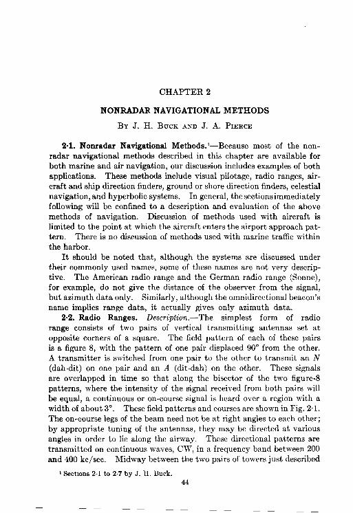
CHAPTER 2
NONRADAR NAVIGATIONAL METHODS
BY J. H. BUCK AND J. A. PIERCE
2.1. Nonradar Navigational Methods.l—Because most of the non-radar navigational methods described in this chapter are available forboth marine and air navigation, our discussion includes examples of bothapplications. These methods include visual pilotage, radio ranges, air-craft and ship direction finders, ground or shore direction finders, celestialnavigation, and hyperbolic systems. In general, the sections immediatelyfollowing will be confined to a description and evaluation of the abovemethods of navigation. Discussion of methods used with aircraft islimited to the point at which the aircraft enters the airport approach pat-tern. There is no discussion of methods used with marine traffic withinthe harbor.
It should be noted that, although the systems are discussed undertheir commonly used names, some of these names are not very descrip-tive. The American radio range and the German radio range (Sonne),for example, do not give the distance of the observer from the signal,but azimuth data only. Similarly, although the omnidirectional beacon’sname implies range data, it actually gives only azimuth data.
2.2. Radio Ranges. Description.—The simplest form of radiorange consists of two pairs of vertical transmitting antennas set atopposite corners of a square. The field pattern of each of these pairsis a figure 8, with the pattern of one pair displaced 90° from the other.A transmitter is switched from one pair to the other to transmit an N(dab-dit) on one pair and an A (alit-dab) on the other. These signalsare overlapped in time so that along the bisector of the two figure-8patterns, where the intensity of the signal received from both pairs willbe equal, a continuous or on-course signal is heard over a region with awidth of about 3°. These field patterns and courses are shown in Fig. 2.1.The on-course legs of the beam need not be at right angles to each other;by appropriate tuning of the antennas, they may be directed at variousangles in order to lie along the airway. These directional patterns aretransmitted on continuous waves, CW, in a frequency band between 200and 400 kc/see. Midway between the two pairs of towers just described
1Ssctions2.1 to 2.7 by J. H. Buck.44
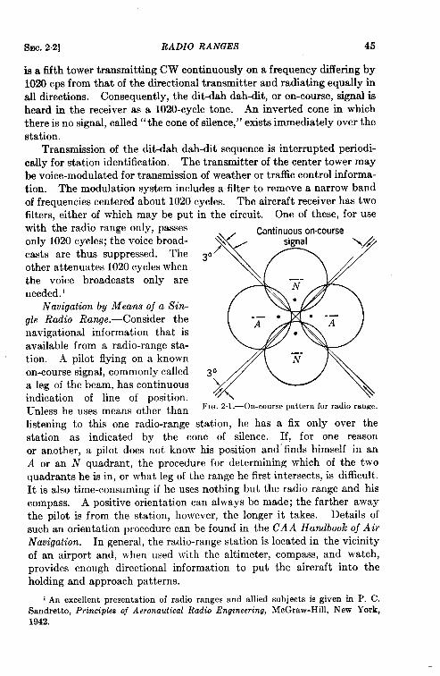
SEC. 2.2] RADIO RANGES 45
is a tifth tower transmitting CW continuously on a frequency differing by1020 cps from that of the directional transmitter and radiating equally inall directions. Consequently, the dlt-dah dah-dit, or on-course, signal isheard in the receiver as a 1020-cycle tone. An inverted cone in whichthere is no signal, called” the cone of silence,” exists immediately over thestation.
Transmission of the dit-dah dah-dit sequence is interrupted periodi-cally for station identification. The transmitter of the center tower maybe voice-modulated for transmission of weather or traffic control informa-tion. The modulation system includes a filter to remove a narrow bandof frequencies centered about 1020 cycles. The aircraft receiver has twofilters, either of which may be put in the circuit. One of these, for usewith the radio range only, passesonly 1020 cycles; the voice broad-casts are thus suppressed. The soother attenuates 1020 cycles whenthe voice broadcasts only areneeded.’
Navigation by Means of a Sin-gle Radio Range. -Consider thenavigational information that isavailable from a radio-range sta-tion. A pilot flying on a knownon-course signal, commonly called 3a leg of the beam, has continuousindication of line of position.Unless he uses means other than FIG. 2.1.—On-course pattern for radio range.
listening to this one radio-range station, he has a fix only over thestation as indicated by the cone of silence. If, for one reasonor another, a pilot does not know his position and” finds himself in anA or an N quadrant, the procedure for determining which of the twoquadrants he is in, or what leg of the range he first intersects, is difficult.It is also time-consuming if he uses nothing but the radio range and hiscompass. A positive orientation can always be made; the farther awaythe pilot is from the station, however, the longer it takes. Details ofsuch an orientation procedure can be found in the CAA Handbook oj AirNavigation. In general, the radio-range station is located in the vicinityof an airport and, when used with the altimeter, compass, and watch,provides enough directional information to put the aircraft into theholding and approach patterns.
1An excellent presentation of radio ranges and allied subjects is given in P. C.Sandretto,Principles oj AeronauticalRadio Engineering,McGraw-Hill, New York,1942.
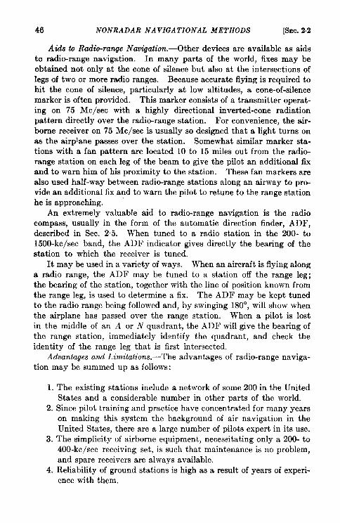
46 I?ONRADAR NAVIGATIONAL METHODS [SEC. 2.2
Aids to Radio-ra~e Navigation. -Other devices are available as aidsto radio-range navigation. In many parts of the world, fixes may beobtained not only at the cone of silence but also at the intersections oflegs of two or more radio ranges. Because accurate flying is required tobit the cone of silence, particularly at low altitudes, a cone-of-silencemarker is often provided. This marker consists of a transmitter operat-ing on 75 Me/see with a highly directional inverted-cone radiationpattern directly over the radio-range station. For convenience, the air-borne receiver on 75 Me/see is usually so designed that a light turns onas the airplane passes over the station. Somewhat similar marker sta-tions with a fan pattern are located 10 to 15 miles out from the radio-range station on each leg of the beam to give the pilot an additional fixand to warn him of his proximity to the station. These fan markers arealso used half-way between radio-range stations along an airway to pro-vide an additional fix and to warn the pilot to retune to the range stationhe is approaching.
An extremely valuable aid to radio-range navigation is the radiocompass, usually in the form of the automatic direction finder, ADF,described in Sec. 25. When tuned to a radio station in the 200- to1500-kc/sec band, the ADF indicator gives directly the bearing of thestation to which the receiver is tuned.
It maybe used in a variety of ways. When an aircraft is flying alonga radio range, the ADF may be tuned to a station off the range leg;the bearing of the station, together with the line of position known fromthe range leg, is used to determine a fix. The ADF may be kept tunedto the radio range being followed and, by swinging 180°, will show whenthe airplane has passed over the range station. When a pilot is lostin the middle of an A or N quadrant, the ADF will give the bearing ofthe range station, immediately identify the quadrant, and check theidentity of the range leg that is first intersected.
Advantages and Limitations.—The advantages of radio-range naviga-tion may be summed up as follows:
1. The existing stations include a network of some 200 in the UnitedStates and a considerable number in other parts of the world.
2. Since pilot training and practice have concentrated for many yearson making this system the background of air navigation in theUnited States, there are a large number of pilots expert in its use.
3. The simplicity of airborne equipment, necessitating only a 200- to400-kc/sec receiving set, is such that maintenance is no problem,and spare receivers are always available.
4. Reliability of ground stations is high as a result of years of experi-ence with them.
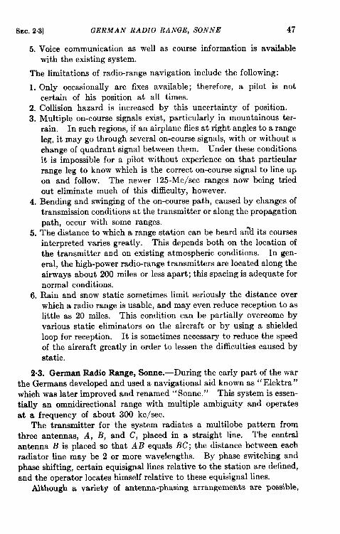
SEC.23] GERMAN RADIO RANGE, SONNE 47
5. Voice communication as well as course information is availablewith the existing system.
The limitations of radio-range navigation include the following:
1. Only occasionally are fixes available; therefore, a pilot is notcertain of hk position at all times.
2. Collision hazard is increased by this uncertainty of position.3. Multiple on-course signals exist, particularly in mountainous ter-
rain. In such regions, if an airplane flies at right angles to a rangeleg, it may go through several on-course signals, with or without achange of quadrant signal between them. Under these conditionsit is impossible for a pilot without experience on that particularrange leg to know which is the correct on-course signal to line upon and follow. The newer 125-Mc/sec ranges now being triedout eliminate much of this difficulty, however.
4. Bending and swinging of the on-course path, caused by changes oftransmission conditions at the transmitter or along the propagationpath, occur with some ranges.
5. The distance to which a range station can be heard ar?d its coursesinterpreted varies greatly. This depends both on the location ofthe transmitter and on existing atmospheric conditions. In gen-eral, the high-power radio-range transmitters are located along theairways about 200 miles or less apart; this spacing is adequate fornormal conditions.
6. Rain and snow static sometimes limit seriously the distance overwhich a radio range is usable, and may even reduce reception to aslittle as 20 miles. This condition can be partially overcome byvarious static eliminators on the aircraft or by using a shieldedloop for reception. It is sometimes necessary to reduce the speedof the aircraft greatly in order to lessen the difficulties caused bystatic.
2.3. German Radio Rsnge, Sonne.-During the early part of the warthe Germans developed and used a navigational aid known as “ Elektra”which was later improved and renamed ‘‘ Sonne. ” This system is essen-tially an omnidirectional range with multiple ambiguity and operatesat a frequency of about 300 kc/see.
The transmitter for the system radiates a multi lobe pattern fromthree antennas, A, B, and C, placed in a straight line. The centralantenna B is placed so that A B equals BC; the distance between eachradiator line may be 2 or more wavelengths. By phase switching andphase shifting, certain equisignal lines relative to the station are defined,and the operator locates himself relative to these equisignal lines.
Although a variety of antenna-phasing amangernents are possible,
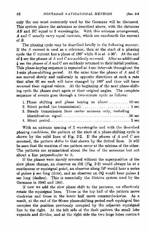
48 NON~ADAR NAVIGATIONAL METHODS [SEC. 2.3
only the one most commonly used by the Germans will be discussed.This system places the antennas as described above, with the distancesAB and BC equal to 3 wavelengths. With this antenna arrangement,A and C usually carry equal currents, which are one-fourth the currentof B.
The phasing cycle may be described briefly in the following manner.If the A current is used as a reference, then at the start of a phasingcycle the C current has a phase of 180e while B is at + 90°. At the endof # sec the phases of A and C are suddenly reversed. After an additional”~ sec the phases of A and C are suddenly returned to their initial position.This phase-keying sequence is repeated at l-see intervals throughout thel-rein phase-shifting period. At the same time the phases of A and Care moved slowly and uniformly in opposite directions at such a ratethat after 60 sec each will have changed by 180° and thus will havereversed their orginal values. At the beginning of the next phase-shift-ing cycle the phases start again at their original angles. The completesequence of events goes through a two-minute cycle as follows:
1. Phase shifting and phase keying as above . 60 sec2. Silent period (no transmission). . . . . . . . . . . . . . lsec3. Steady transmission from center antenna only, including
identification signal . . . . . . . . . .56sec4. Silent period . . . . . . . . . . . . . . . . . . . . . . . . . . . . . . . . . . . . . . . ..3sec
With an antenna spacing of 3 wavelengths and with the describedphasing conditions, the pattern at the start of a phase-shifting cycle isshown by the solid lines of Fig. 2.2. If the phases of A and C arereversed, the pattern shifts to that shown by the dotted lines. It willbe seen that the maxima of one pattern occur at the minima of the other.The patterns are symmetrical about the line of the antennas but notabout a line perpendicular to it.
If the phases were merely reversed without the superposition of theslow phase change, an observer on OR (Fig. 2“2) would always be at acontinuous or equisignal point, an observer along OP would hear a seriesof pulses ~ sec long (dots), and an observer on OQ would hear pulses &sec long (dashes). This is essentially the Elektra system used by theGermans in 1940 and 1941.
If now we add the slow phase shift to the patterns, we effectivelyrotate the equisignal lines. Those in the top half of the pattern moveclockwise and those in the lower half move counterclockwise. As aresult, at the end of the 60-sec phase-shifting period each equisignal lineoccupies the position previously occupied by the adjacent equisignalline to the right. At the left side of the dash pattern the small lobeexpands and divides, and at the right side the two large lobes contract
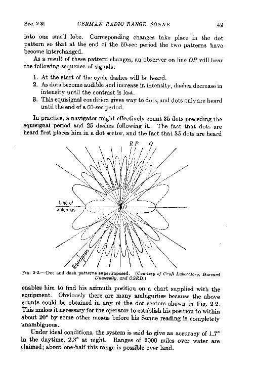
SEC. 2.3] GERMAN RADIO RANGE, SONNE 49
into one small lobe. Corresponding changes take place in the dotpattern so that at the end of the 60-sec period the two patterns havebecome interchanged.
As a result of these pattern changes, an observer on line OP will hearthe following sequence of signals:
1. At the start of the cycle dashes will be heard.2. AS dots become audible and increase in intensity, dashes decrease in
intensity until the contrast is lost.3. This equisignal condition gives way to dots, and dots only are heard
until the end of a 60-sec period.
In practice, a navigator might effectively count 35 dots preceding theequisignal period and 25 dashes following it. The fact that dots areheard first places him in a dot sector, and the fact that 35 dots are heard
RP Q
FIG. 2.2.—Dot and dash patterns superimposed. (Courtenuof Cruft Laborato~U, Hanm.dUnitwrati~, and OSRD.)
enables him to find his azimuth position on a chart supplied with theequipment. Obviously there are many ambiguities because the abovecounts could be obtained in any of the dot sectors shown in Fig. 2.2.This makes it necessary for the operator to establish his position to withinabout 20° by some other means before his Sonne reading is completelyunambiguous.
Under ideaf conditions, the system is said to give an accuracy of 1.7oin the daytime, 2.3° at night. Ranges of 2000 miles over water areclaimed; about one-half this range is possible over land.
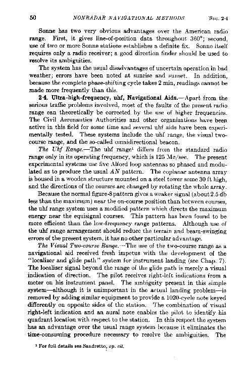
50 NONRADAR NAVIGATIONAL METHODS [SEC. 2.4
Sonne has two very obvious advantages over the American radiorange. First, it gives line-of-position data throughout 360°; second,use of two or more Sonne stations establishes a definite fix. Sonne itselfrequires only a radio receiver; a good direction finder should be used toresolve its ambiguities.
The system has the usual disadvantages of uncertain operation in badweather; errors have been noted at sunrise and sunset. In addition,because the complete phase-shifting cycle takes 2 rein, readings cannot bemade more frequently than this.
2.4. Ultra-high-frequency, uhf, Navigational Aids.-Apart from theserious traffic problems involved, most of the faults of the present radiorange can theoretically be corrected by the use of higher frequencies.The Civil Aeronautics Authorities and other organizations have beenactive in this field for some time and several uhf aids have been experi-mentally tested. These systems include the uhf range, the visual two-course range, and the so-called omnidirectional beacon.
The Uhf Range.-The uhf rangel differs from the standard radiorange only in its operating frequency, which is 125 .Mc/sec. The presentexperimental systems use five Alford loop antennas so phased and modu-lated as to produce the usual AN pattern. The coplanar antenna arrayis housed in a wooden structure mounted on a steel tower some 30 ft high,and the directions of the courses are changed by rotating the whole array.
Because the normal figure-8 pattern gives a weaker signal (about 2.5 dbless than the maximum) near the on-course position than between courses,the uhf range system uses a modified pattern which directs the maximumenergy near the equisignal courses. This pattern has been found to bemore efficient than the low-frequency range patterns. Although use ofthe uhf range arrangement should reduce the terrain and beam-swingingerrors of the present system, it has no other particular advantage.
The Visual Two-course Range.-The use of the two-course range as anavigational aid received fresh impetus with the development of the“localizer and glide path” system for instrument landing (see Chap. 7).The localizer signal beyond the range of the glide path is merely a visualindication of direction. The pilot receives right-left indications from ameter on his instrument panel. The ambiguity present in this simplesystem-although it is unimportant in the actual landing problem—isremoved by adding similar equipment to provide a 1020-cycle note keyeddifferently on opposite sides of the station. The combination of visualright-left indication and an aural note enables the pilot to identify hisquadrant location with respect to the station. In this respect the systemhaa an advantage over the usual range system because it eliminates thetime-consuming procedure necessary to resolve the ambiguities, The
1For full detailsseeSandretto,op. cd.
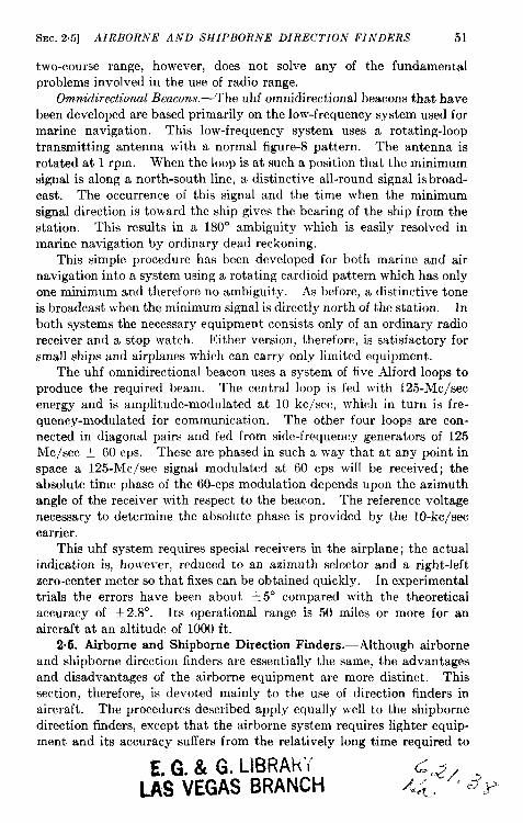
~EC. 25] AIRBORNE AND SHIPBORNE DIRECTION FINDERS 51
two-course range, however, does not solve any of the fundamentalproblems involved in the use of radio range.
Omnidirectional Beacons.—The uhf omnidirectional beacons that havebeen developed are based primarily on the low-frequency system used formarine navigation. This low-frequency system uses a rotating-looptransmitting antenna with a normal figure-8 pattern. The antenna isrotated at 1 rpm. When the loop is at such a position that the minimumsignal is along a north-south line, a distinctive all-round signal is broad-cast. The occurrence of this signal and the time when the minimumsignal direction is toward the ship gives the bearing of the ship from thestation. Thk results in a 180° ambiguity which is easily resolved inmarine navigation by ordinary dead reckoning.
This simple procedure has been developed for both marine and airnavigation into a system using a rotating cardioid pattern which has onlyone minimum and therefore no ambiguity. As before, a distinctive toneis broadcast when the minimum signal is directly north of the station. Inboth systems the necessary equipment consists only of an ordinary radioreceiver and a stop watch. Either version, therefore, is satisfactory forsmall ships and airplanes which can carry only limited equipment.
The uhf omnidirectional beacon uses a system of five Alford loops toproduce the required beam. The central loop is fed with 125-Mc/secenergy and is amplitude-modulated at 10 kc/see, which in turn is fre-quency-modulated for communication. The other four loops are con-nected in diagonal pairs and fed from side-frequent y generators of 125Me/see f 60 cps. These are phased in such a way that at any point inspace a 125-M c/sec signal modulated at 60 cps wil! be received; theabsolute time phase of the 60-cps modulation depends upon the azimuthangle of the receiver with respect to the beacon. The reference voltagenecessary to determine the absolute phase is provided by the 10-kc/seccarrier.
This uhf system requires special receivers in the airplane; the actualindication is, however, reduced to an azimuth selector and a right-leftzero-center meter so that fixes can be obtained quickly. In experimentaltrials the errors have been about + 5° compared with the theoreticalaccuracy of t 2.8°. Its operational range is 50 miles or more for anaircraft at an altitude of 1000 ft.
2.6. Airborne and Shipbome Direction Finders.-Although airborneand shipborne direction finders are essentially the same, the advantagesand disadvantages of the airborne equipment are more distinct. Thissection, therefore, is devoted mainly to the use of direction finders inaircraft. The procedures described apply equally well to the shipbornedirection finders, except that the airborne system requires lighter equip-ment and its accuracy suffers from the relatively long time required to
E.G.& G. I-lBRAk’I’LAS VEGAS BRANCH
52 NONRADAR NAVIGATIONAL METHODS [SEC, 25
obtain fixes. Both direction finders consist primarily of a loop antennalused in conjunction with an azimuth indicator, some type of loop-rotatingmechanism, and a radio receiver.
Fundamentally, the loop and its associated equipment are merely themeans of detecting a radio signal and determining the direction fromwhich it comes. If the plane of the loop is at right angles to the directionof the signal, a minimum voltage is induced. The bearing is alwaysobtained at this null position because the rate of variation of inducedvoltage with loop position is much greater around this point than aroundthe maximum signal position. The azimuth indicator shows the directionperpendicular to the plane of the loop. It therefore indicates the direc-tion of the transmitting station when the loop is rotated for minimumsignal.
If this equipment only is used, the pilot or navigator tunes his receiverto the frequency of the station that he wishes to locate and then rotatesthe loop until the signal reaches a minimum. It is important to notethat because the loop antenna has a figure-8 pattern this indication isambiguous; the station may be in one of two directions, 180° apart,Such “fixes” on two or more stations, however, enable the operator toeliminate this ambiguity and to determine his position. This simpleequipment has, in recent years, been developed progressively into theradio compass and various types of automatic direction finders. z
Both the radio compass and the automatic direction finder havevertical antennas in addition to the loop antennas. The receiver, ineach case, then, is fed by two antennas, one with a figure-8 pattern, theother with a circular pattern. If the signals from these are properlyphased in azimuth a cardioid pattern which is unidirectional in its indi-cation results.
The radio compass uses the cardioid pattern, but is operated in suchaway that some of the unidirectional property of the pattern is lost. Theloop is rigidly mounted with its plane at right angles to the major axisof the aircraft, and the output signal of the loop is rapidly reversedby electronic switching. As a result, the phase of the loop signal ischanged by 180°. This phase change, added to the signal from the verti-cal antenna, has the effect of rapidly reversing the cardioid pattern. Thetotal signal is fed to a zero-center meter and, depending on the positionof the station relative to the airplane, the needle of the radio compass willdeflect to the right or left. If the pilot turns the airplane to obtain zerodeflection the station will be placed either directly ahead of or behind theairplane. Another simple turn can tell the pilot immediately which is the
1Full descriptionof the loop antennaused can be found in Sandretto, op. cit.,Chap. 4.
2Sandretto,10C.cit.
.
SEC. 2.5] AIRBORNE AND SHIPBORNE DZRECTION FINDERS 53
case. The radio compass is usually used as a method of “homing” butgives no indication of distance from the station.
The radio compass is very difficult to use in a cross wind because noallowance is made for drift. If the pilot carefully keeps it centered whilehis airplane is being blown off course by a cross wind, he flies a curvedpath and eventually approaches the station approximately upwind.Such a path is a long route and requires constant adjustment if the windis very strong.
Use of ADF.-Several types of automatic direction finders whichuse the radio compass as a basis have been developed. Most of theseuse a rotatable instead of a fixed loop, following the system patented byF. L. Mosely. In simple form the loop is rotated until the needle of theradio compass returns to zero; the loop direction at this point is indicatedon a bearing indicator by means of a flexible shaft connection. Bearingson two or more such stations, of course, provide a fix. If the airplane isexactly on course on a radio-range leg, a fix can be obtained by one ADFsetting.
Rather simple additions to this system make the direction findercompletely automatic. As long as the receiver is tuned to the requiredsignal, the loop, and hence the indicator, remains pointed at the station.This gives the pilot a continuous indication of his direction from thisstation.
Basically, any type of radio compass is simple to use; a great deal ofcare is required, however, if reasonable accuracy is to be obtained.Under the best conditions of smooth flight and good received signals, theerrors are limited to f 2°. Usually, however, they range from + 3° to~ 5°. The accuracy depends not only on skilled operation and steadyflight but also on the accuracy of the calibration of the loop. Thiscalibration must be done carefully for each airplane and for each positionof the loop because the metal structure of the airplane varies the amountof the energy received by the loop from certain directions.
Advantages and Limitations.—The advantages of the airborne radiocompass and automatic direction finder as navigational aids may besummarized as follows:
1. Because the system may be tuned to any radio station the pilotcan always find a” homing” station over reasonably well-populatedcountry.
2. The airborne equipment is simple and easy to use.
The disadvantages are as follows:
1. The system is subject to all of the bad weather faults of the radiorange including reduction of range due to precipitation static.
54 NONRADAR NAVIGATIONAL METHODS [8EC. 2.6
2. Physical features of the terrain can give reflections that will causefalse indications of direction.
3. Because there is no indication of distance from any one station,position fixes must be obtained by plotting bearings on appropriatemaps, a task that is time-consuming and extremely awkward fora pilot.
4. Collision hazard isserious because theexact position of the aircraftis not known.
2.6. Ground Direction Finders.-This aid to navigation can be usedalmost equally well with marine or airborne traffic. Because of the speedinvolved, however, it is more difficult to use with airplanes. It is essen-tially the same as the airborne or shipborne direction finders except thatthe measurements are taken on the ground and the burden of calculationis placed on the ground station, and the navigator is given a fix by directradio communication.
Like all other radio navigational aids, ground direction finding wasfirst tried at relatively low frequencies; in fact, it is still largely used atthese frequencies. The United States–Canadian direction-finding sta-tions along the Atlantic coast, for example, are nearly all on 375 kc.Similar frequencies were used in Europe, where the system was the firstnavigational aid used by airplanes. During the war, however, operationwas very successful on 3000 to 7000 kc. Higher frequencies are beingtried to eliminate the usual difficulties-static, bending, etc., at longwavelengths.
Much work has been done on ground-based equipment. The Adcockdirection finder and the spaced-loop direction finderl eliminate most ofthe errors due to abnormal polarization, but successful operation stilldepends on the station operator’s ability to take bearings quickly andaccurately.
As first used, the ground direction-finding system did not coordinatethe ground stations. A navigator would request a fix, and while hetransmitted, two or more stations would determine the direction of hissignal and report this to him with their identity. From these data andthe known location of the stations the navigator could determine hisposition. The directions given would, of course, be the actual directionof arrival of the radio signal reaching the station over a great circle course.
This method was satisfactory for most marine traffic, because thetime necessary for the calculations could be taken. With ships close toshore and airplanes approaching their bases, however, it has been foundmuch more satisfactory to operate the ground stations in teams. The
1Full descriptionsof those antenna systems are given in Sandretto, op cit.,Chaps8.
SEC. 2.7] CELESTIAL NA VI(7A TION 55
stations in any one group report bearings to a central position where allcalculations of the navigator’s position can be made rapidly and accu-rately and transmitted to him.
During the war this latter method of ground direction-finding wasused very successfully by transatlantic airplanes. Although onlymedium-high frequencies were used, the operators became so skilled thatfixes could be transmitted very rapidly. In fact, instead of giving fixes,the stations often broadcast headings for the aircraft to fly; in badweather they were able to guide airplanes into their final approach path.This kind of performance is unusual and depends on the use of excep-tionally well-trained and experienced operators.
In many ways this system, if it is reliably operated, is the mostsatisfactory of all the radio navigational aids because:
1. All the measuring equipment is on the ground; calibrations aremore accurate, therefore, and can be checked frequently. Calcu-lations can also be made more quickly and more accurately in apermanent ground installation than inan airplane.
2. Studies of terrain effects and reflections from nearby objects canbe made in order to eliminate or allow for errors in each station.
3. Constant monitoring assures proper operation of each station.The usual difficulties of fading, beam swinging, and bad weatherstatic are still present, however. In addition, the traffic-handlingcapacity is too small for an active airport if the system is being usedwith aircraft.
2.7. Celestial Navigation. -Until very recently the only navigationalaid available to marine traffic and to aircraft on long flights over waterwas celestial navigation. This aid is primarily dependent on three things:
1. Clear weather so as to see the sun or the stars.2. An accurate sextant and the necessary charts and tables.3. A reasonably well-trained observer.
When the above conditions are filled, the position of a ship can befound to within 1 or 2 miles. A ship, however, is a relatively steadyplatform for observation, and very accurate sextants can be used withthe sea horizon as a reference level. On the other hand, when a ship issailing under complete overcast, no readings are possible. Before thedays of radio direction-finding, the only means of navigation under suchcircumstances was dead reckoning. Fortunately for marine traffic, deadreckoning is reasonably reliable because of the accuracy of speed indica-tors and accurate knowledge of ocean currents.
For air navigation, however, a sextant with an artificial horizon wasnecessary before celestial navigation could be used at all. Such a sex-
56 NONRADAR NAVIGATIONAL METHODS [SEC. 2.8
tant, using a bubble level, makes possible readings from an airplane, butaccuracies are no better than t 10 to f 20 miles. To offset this dis-advantage, the navigator of an airplane is often able to obtain readingsby flying “above the weather.)’
Despite the obvious disadvantage of complete dependence on fairweather, celestial navigation has the advantage of simple rugged equip-ment and it pleases those navigators who like to feel independent of out-side aid. It should be noted, however, that its accuracy is independentof location and is inadequate for aircraft about to let down throughheavy clouds to a landing in dangerous terrain.
LORAN AND OTHER NAVIGATIONAL NETS
BY J. A. PIERCE
2.8. Hyperbolic Systems.—Hyperbolic navigation is achieved whensynchronized signais having a known velocity of propagation are trans-mitted from at least three known points, and when the relative times ofarrival of these signals are measured and interpreted by a navigator.The general principle of hyperbolic navigation is shown in Fig. 2.3.
The signals may be transmitted and received by any known means;at present, radio is the only mechanism which is accurate at long ranges.Various sorts of signals, ranging from continuous waves through modu-lated waves to pulses, may be used. Pulse transmission is preferred formany present applications because ambiguity is minimized and thepower supplied to the transmitters may be kept low. Pulse transmissionordinarily requires more space in the radio spectrum (that is, greaterchannel width) than does continuous-wave transmission; in a pulsenavigation system, however, this apparent disadvantage may be entirelyillusory because a number of methods of identifying signals becomeavailable by the very use of pulses. Thus, pulsed systems permit thetransmission of a large number of signals within a common radio-fre-quency channel without excessive confusion, but continuous-wavesystems require the use of a separate radio frequency for each componentto provide identification.
The hyperbolic principle is now used by only three operating systemsif we include those in which the base lines are so short that each is con-tained within a single transmitting site. Examples of these last are theOmnidirectional Range and the German Sonne systems. Of the threehyperbolic systems, the pulse method is exemplified by two, Gee andLoran, while the continuous-wave technique is used in the Decca system.
Consider two fixed stations that transmit signals at the same instant.If a navigator receives these signals simultaneously, and if the velocity ofpropagation can be considered to be equal over the two paths, he knows
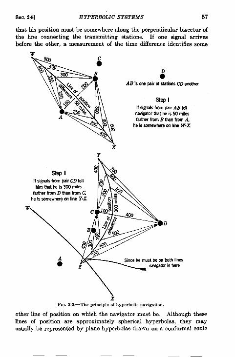
SEC. 2:8] HYPERBOLIC SYSTEMS 57
that his position must be somewhere along the perpendicular bisector ofthe line connecting the transmitting stations. If one signal arrivesbefore the other, a measurement of the time difference identifies some
w
6All Is one pair of stations CD another
Step IIf signals from pair AB tell
navigator that he is 50 miles
farther from B than from A,heissomewhere on line W-X.
Y
stepIIIf signals from pair CD tell
him that he is 300 miles
farther from D than from C,
he is somewhere on line Y-Z.
Since he must be on both lines
xFIG. 2.3.—The principle of hyperbolic navigation.
other line of position on which the navigator must be. Although theselines of position are approximately spherical hyperbolas, they mayusually be represented by plane hyperbolas drawn on a conformal conic
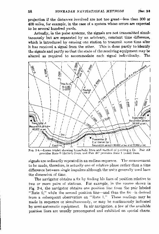
58 NONRADAR NAVIGATIONAL METHODS [fhc. 2s8
projection if the distances involved are not too great—less than 300 or400 miles, for example, in the case of a system whose errors are expectedto be several hundred yards.
Actually, in the pulse systems, the signals are not transmitted simul-taneously but are separated by an arbitrary, constant time difference,which is introduced by causing one station to transmit some time afterit has received a signal from the other. Thk is done partly to identifythe signals and partly so that the state of the receiving equipment maybealtered as required to accommodate each signal individually. The
T\
\
\%\s.
\\\\ \\ I\ I\\
\\
TransmltierC
/
///’
// / Recurrenceperiod=40,000p secand39,900.Ukc
Fm. 2.4.—Loran triplet showing hyperbolic lines and method of plotting a fix. Pair ABprovides Rate O (dotted) lines, and Pair BC provides Rate 1 (solid) lines.
signals are ordinarily repeated in an endless sequence. The measurementto be made, therefore, is actually one of relative phase rather than a timedifference between single impulses although the units generally used havethe dimension of time.
The navigator obtains a fix by finding his lines of position relative totwo or more pairs of stations. For example, in the course shown inFig. 2.4, the navigator obtains one position line from the pair labeled“ Rate O,” while the second position line—and thus the fix-is derivedfrom a subsequent observation on “ Rate 1.“ These readings may bemade in sequence or simultaneously, or may be continuously indicatedby semi-automatic equipment. In air navigation, a few of the availableposition lines are usually precomputed and exhibited on special charts.
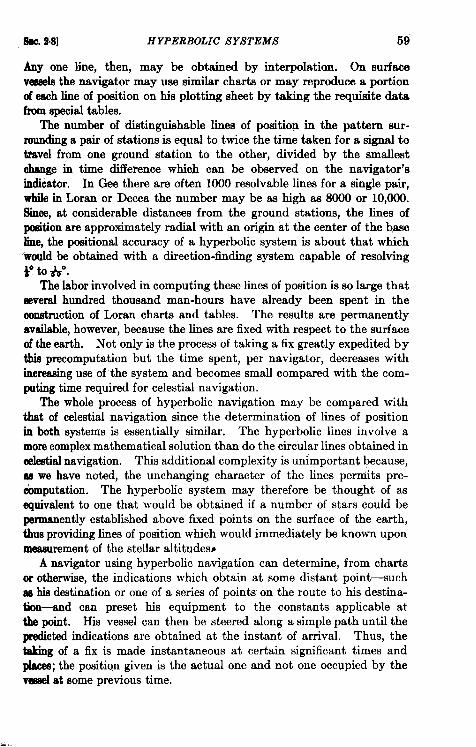
kc. 2,8] HYPERBOLIC SYSTEMS 59
Any one line, then, may be obtained by interpolation. On surfacevesselsthe navigator may use similar charts or may reproduce a portionof each line of position on his plotting sheet by taking the requisite datafrom spbcial tables.
The number of distinguishable lines of position in the pattern sur-rounding a pair of stations is equal to twice the time taken for a signal totravel from one ground station to the other, divided by the smallestchange in time difference whio,h can be observed on the navigator’sindicator. In Gee there are often 1000 resolvable lines for a single pair,while in Loran or Decca the number may be as high as 8000 or 10,000.Since, at considerable distances from the ground stations, the lines ofposition are approximately radial with an origin at the center of the baseline, the positional accuracy of a hyperbolic system is about that which‘would be obtained with a direction-finding system capable of resolvingVtow.
The labor involved in computing these limes of position is so large thatseveral hundred thousand man-hours have already been spent in themnstmction of Loran charts and tables. The results are permanentlyavailable, however, because the lines are fixed with respect to the surfaceof the earth. Not only is the process of taking a fix greatly expedited b ythis precomputation but the time spent, per navigator, decreases withincreasing use of the system and becomes small compared with the com-puting time required for celestial navigation.
The whole process of hyperbolic navigation may be compared withthat of celestial navigation since the determination of lines of positionin both systems is essentially similar. The hyperbolic lines involve amorecomplex mathematical solution than do the circular lines obtained incelestialnavigation. This additional complexity is unimportant because,as we have noted, the unchanging character of the lines perniits pre-computation. The hyperbolic system may therefore be thought of asequivalent to one that would be obtained if a number of stars could bepermanently established above fixed points on the surface of the earth,thus providing lines of position which would immediately be known uponmeasurement of the stellar altitudes~
A navigator using hyperbolic navigation can determine, from chartsor otherwise, the indications which obtain at some distant point—suchas his destination or one of a series of points on the route to his destina-tion-and can preset his equipment to the constants applicable atthe point. His vessel can then be steered along a simple path until thepredicted indications are obtained at the instant of arrival. Thus, thetaking of a fix is made instantaneous at certain significant times andplacea; the position given is the actual one and not one occupied by thevesselat some previous time.
60 NONRADAR NAVIGATIONAL METHODS [i?tEc.2.9
The great advantage of hyperbolic navigation over radar beaconsystemsl that might offer equal orgreater precision over thesame rangeais that saturation of the ground facilities is impossible. The transmittersof a hyperbolic system can be compared with a family of Iighthouseawhose keepers simply transmit intelligence as prearranged. There is nocorrelation between the activities of the navigators and those of theoperators of the transmitters, and the behavior of the system does notdepend upon whether one or ten or thousands of navigators are makinguse of the service it provides.
2-9. Gee.—The Gee system was the primary radio navigational aidduring the European War. Its successes were far too numerous and toowell known to need recounting here. The Gee system was put i&ooperation in March 1942. Its usefulness over Germany varied somewhatwith changes in types and magnitude of enemy jamming, but it servedcontinuously as an invaluable homing system for the RAF and theAmerican air forces, as the coverage chart in Fig. 2“5 illustrates.
Gee stations radiate about 300 kw on frequencies between 20 and 85Me/see and therefore give service at somewhat more than optical ranges.Near the surface of the earth, their useful range is not over 150 miles, buttheir reliable service radius increases with altitude to a maximum of 450miles. This range is attainable, in the case of fixed stations with highantennas, for aircraft at 30,000 ft. The pulses used are about 6 psec inlength (as seen on the oscilloscope) and the method of comparison is suchthat time differences can be estimated to about one-tenth of the pulselength.
Base lines in the Gee system are usually about 75 miles long and aredisposed with the master station in the center and ‘the two or three“slaves” dispersed around the circumference of a rough circle. Eachchain formed by such a group of stations operates on a different radiofrequency. Six frequencies are available in each of the four bandsassigned to the system. (This flexibility was, of course, of great value inavoiding the worst effects of enemy jamming of the British stations.)
The navigator’s indicating equipment presents visually a family offour or five pulses, two being transmitted from the master station and onefrom each slave. A double time base (one upper and one lower trace)with a total length of 4000 ~sec is employed on the cathode-ray tube.This is shown in circle a of Fig. 26.
By the use of delay circuits, four fast cathode-ray sweeps can beinitiated at such times that two of the sweeps contain and exhibit themaster-station pulses and the other two exhibit two of the slave pulsesin inverted form. Each of the slave pulses may be adjusted laterally tolie with its base coincident with the base of one of the master pulses.
1See Chap. 7.
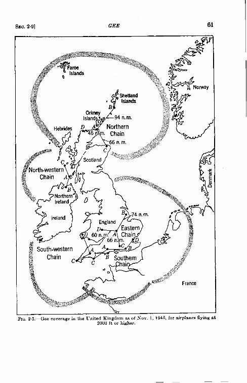
SEC. 2.9] GEE 61
k-8
&. . ,.. . .
Fm. 2,5.—Gee coverage in the United Kingdom as of NOV.1, 1945, for rurplanesnylng at2000 ft or higher.
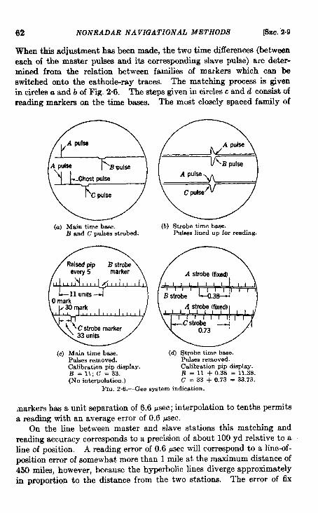
62 NONRADAR NAVIGATIONAL METHODS [SEC. “2.9
When this adjustment haa been made, the two time differences (betweeneach of the master pulses and its corresponding slave pulse) are deter-mined from the relation between families of markers which can beswitched onto the cathod+ray traces. The matching process is givenin circles a and b of Fig. 2-6. The steps given in circles c and d consist ofreading markers on the time bases. The most closely spaced family of
(a) Main time base.B and C pulses strobed.
me!5
A pld=
C pulse
(b) Strobe time base.Pufses lined up for reading.
(c) Main time base. (d) Strobe time base.Pulses removed. Pulses removed.Calibration pip display. Calibration pip display.B=ll; C= 33. B = 11 + 0,3S = 11.3S.(No interpolation,) c = 33 + 0.73 = 33.73.
FM-.2.6.—Gee system indication.
markers has a unit separation of 6.6 psec; interpolation to tenths permitsa reading with an average error of 0.6 psec.
On the line between master and slave stations this matching andreading accuracy corresponds to a precision of about 100 yd relative to aline of position. A reading error of 0.6 psec will correspond to a line-of-position error of somewhat more than 1 mile at the maximum distance of450 miles, however, because the hyperbolic lines diverge approximatelyin proportion to the distance from the two stations. The error of fix
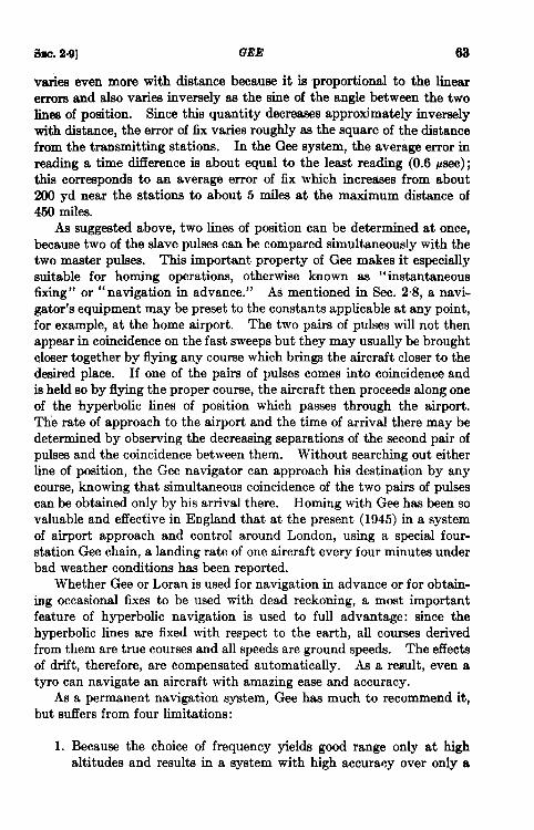
SEC. 24)] GEE 63
varies even more with distance because it is proportional to the linearerrors and also varies inversely ae the sine of the angle between the twohnes of position. Since this quantity decreases approximately inverselywith distance, the error of fix varies roughly as the square of the distancefrom the transmitting stations. In the Gee system, the average error inreading a time difference is about equal to the least reading (0.6 psec);this corresponds to an average error of fix which increases from about200 yd near the stations to about 5 miles at the maximum distance of450 miles.
As suggested above, two lines of position can be determined at once,because two of the slave pulses can be compared simultaneously with thetwo master pulses. This important property of Gee makes it especiallysuitable for homing operations, otherwise known as “instantaneous6xing” or “ navigation in advance.” As mentioned in Sec. 2.8, a navi-gator’s equipment may be preset to the constants applicable at any point,for example, at the home airport. The two pairs of pulses will not thenappear in coincidence on the fast sweeps but they may usually be broughtcloser together by flying any course which brings the aircraft closer to thedesired place. If one of the pairs of pulses comes into coincidence andis held so by flying the proper course, the aircraft then proceeds along oneof the hyperbolic lines of position which passes through the airport.The rate of approach to the airport and the time of arrival there maybedetermined by observing the decreasing separations of the second pair ofpulses and the coincidence between them. Without searching out eitherline of position, the Gee navigator can approach his destination by anycourse, knowing that simultaneous coincidence of the two pairs of pulsescan be obtained only by his arrival there. Homing with Gee has been sovaluable and effective in England that at the present (1945) in a systemof airport approach and control around London, using a special four-station Gee chain, a landing rate of one aircraft every four minutes underbad weather conditions has been reported.
Whether Gee or Loran is used for navigation in advance or for obtain-ing occasional fixes to be used with dead reckoning, a most importantfeature of hyperbolic navigation is used to full advantage: since thehyperbolic lines are fixed with respect to the earth, all courses derivedfrom them are true courses and all speeds are ground speeds. The effectsof drift, therefore, are compensated automatically. As a result, even atyro can navigate an aircraft with amazing ease and accuracy.
As a permanent navigation system, Gee has much to recommend it,but suffers from four limitations:
1. Because the choice of frequency yields good range only at highaltitudes and results in a system with high accuracy over only a
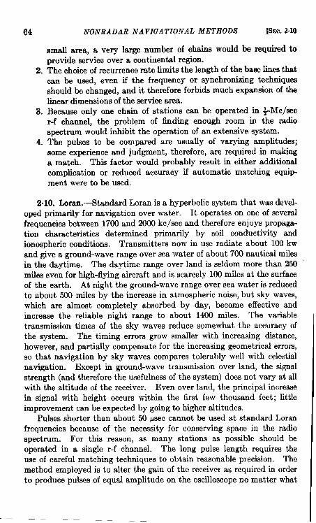
64
2.
3.
4.
NONRADAR NAVIGATIONAL METHODS [SEC. 2.10
small area, a very large number of chains would be required toprovide service over a continental region.The choice of recurrence rate limits the length of the base lines thatcan be used, even if the frequency or synchronizing techniquesshould be changed, and it there fore forbids much expmionof thefinear dimensions of the service area.Because ordy one chain of stations can be operated in +Mc/secr-f channel, the problem of finding enough room in the radiospectrum would inhibit the operation of an extensive system.The I-X.&W to be compared are usually of varying amplitudes;some experience and judgment, therefore, are required in makinga match. This factor would probably result in either additionalcomplication or reduced accuracy if automatic matching equip-ment were to be used.
201O. Lorrtn.-i%andard Loran is a hyperbolic system that was devel-oped primarily for navigation over water. It operates on one of severalfrequencies between 1700 and 2000 kc/see and therefore enjoys propaga-tion characteristics determined primarily by soil conductivity andionospheric conditions. Transmitters now in use radiate about 100 kwand give a ground-wave range over sea water of about 700 nautical milesin the daytime. The daytime range over land is seldom more than 250miles even for high-flying aircraft and is scarcely 100 miles at the surfaceof the earth. At night the ground-wave range over sea water is reducedto about 500 miles by the increase in atmospheric noise, but sky waves,which are almost completely absorbed by day, become effective andincrease the reliable night range to about 1400 miles. The variabletransmission times of the sky waves reduce somewhat the accuracy ofthe system. The “timing errors grow smaller with increasing distance,however, and partially compensate for the increasing geometrical errors,so that navigation by sky waves compares tolerably well with celestialnavigation. Except in ground-wave transmission over land, the signalstrength (and therefore the usefulness of the system) does not vary at allwith the altitude of the receiver. Even over land, the principal increasein signal with height occurs within the first few thousand feet; littleimprovement can be expected by going to higher altitudes.
Pulses shorter than about 50 ~sec cannot be used at standard Loranfrequencies because of the necessity for conserving space in the radiospectrum. For this reason, as many stations as possible should beoperated in a single r-f channel. The long pulse length requires theuse of careful matching techniques to obtain reasonable precision. Themethod employed is to alter the gain of the receiver as required in orderto produce pulses of equal amplitude on the oscilloscope no matter what
I
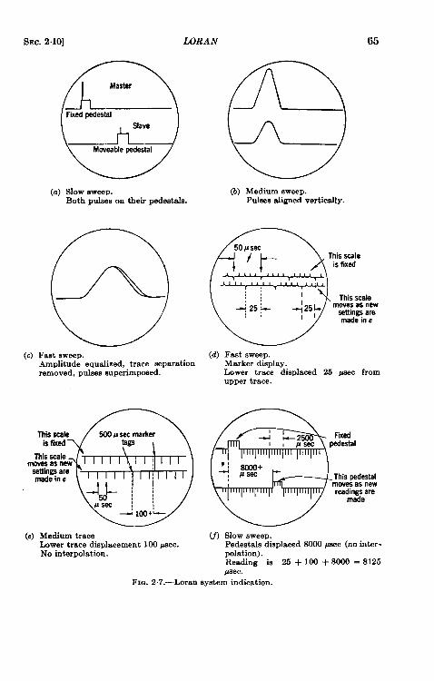
SEC. 2.10] WRAN 65
(c)
QLFixadpedestal
Slave
Mweable pedestal
(a) slow sweep.Both pnlsas on their pedestals.
(aFast sweep.Amplitude equalized, trace separationremoved, pulses superimposed.
@
ITdsscale 500Paecmarkerisfixed tsga
7hisscalemwaaasnew
aastingearemadein c
d,} ~ ~
#aec:!4 Iw+k
(e) Medium traceLower trace displacement 100 paec.No interpolation.
(b) Medium uweep.Pukes aligned vertically.
R50P Sec
I’t
This scaleis fixed
:: II This scala::G25~ ~25~ mwes as new
aathgs aremade in c
(d) Fast SW&P.Marker display.Lower trace displaced 25 psec fromupper trace.
@
-J -2 Fixad1, J! Sac pedestal
J 80W+laaec 1- This pedestal
mwea as newreadings are
made
(f) SIOW sweep.Pedestrdadisplaced 8000 @ac (no inter-polation).Reading ia 25 + 100 + 8000 = 8125paec.
FIG. 2.7.—Loran eystem indication.
66 NONRADAR NAVIGATIONAL METHODS [SEC.2.10
distances orother attenuating factors maybe present in the two trans-nuseion paths. The pulses may then be superimposed accurately,provided that, as radiated, they are made su5ciently identical by alltransmitters. Such a measurement maybe made with a prec@ion of 1 percent of the pulse length if the signal-t~noiee ratio is satisfactory. Figure2.7 depicts the Loran reading process. Figure 2.8 is a picture of theairborne and shipborne equipments.
The meth~ of measurement is similar to that used in the Gee system,except that no effort is made to indicate two lines of position at once.This is a very important exception. The reason for it is somewhatinvolved and will be discussed below. The navigator can make readingsto the nearest microsecond-tw~thirds of the precision of the Gee read-ing. The base lines ordinarily used are about 300 miles in length so thatthe geometrical factors at 1400 miles are similar to those of Gee at 350miles.
If, as is common, three Loran stations are used as a triplet, the accu-racy of fix may be compared to that of Gee because the same factorsapply. The average error at short distances is about 300 yd and increasessmoothly throughout the ground-wave service area to a little more than1 mile at 700 miles. At night, sky waves may be used at distancesbetween 300 and 1400 miles with average errors ranging from 1.5 toabout 8 miles.
The average errors of fix at long ranges are often smaller than theseestimates because selected Loran pairs can often be found which supplybetter crossing angles than are obtainable from a lone triplet. Loranstations are often installed as a chain consisting of three or more stations,along a coast line or between islands. In each pair, pulses are trans-mitted at a specially assigned recurrence rate, one of a family that haveratios 400 to 399 to 398 and so on . . . to 393. Thus, as many as eightpairs, all employing the same r-f channel, may operate as a chain. Thew ~dark squjx.wxd cam .!Mad,iusted ta .s.ymdmmize with any one ofthese rates to identify a particular pair. The pulses at the chosen ratethen appear stationary and their time difference can be measured. Thepulses from all other stations pass across the screen at such speeds thatconfusion is negligible. Stations between the ends of a chain ordinarilyare “double”; that is, they act in all essentials as two independent sta-tions at the same location, so that a chain consists of a number of separatepairs set accurately end to end.
The navigator can choose from among these the pairs he will use fordetermining a fix in the same way that he would choose stars for celestialnavigation. In other words, he takes those whose lines of position crossat the most favorable angle. In fact, he frequently uses thre~ or four-line fixes for maximum precision, because the reading of a single line of
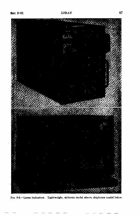
BEC.2.10] LORAN 67
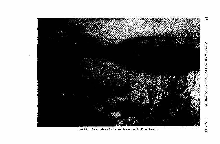
68N
ON
RA
DA
RN
AV
IGA
TIO
NA
LM
ET
HO
DS
[SE(!.2.10
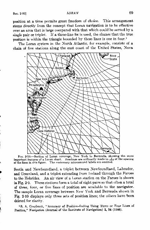
i
I
SEC. 2.10] WRAN 69
position at a time permits great freedom of choice. This arrangementstems directly from the concept that Loran navigation is to be effectiveover an area that is large compared with that which could be served by asingle pair or triplet. If a three-line fix is used, the chance that the trueposition is within the triangle bounded by these lines is one in four. 1
The Loran system in the North Atlantic, for example, consists of achain of five stations along the east coast of the United States, Nova
.
Fm. 2.10.—Sectionof Loran coverage,New York to Bermuda,showingthe moreimportantfeaturesof a Loran chart. Readings are ordinarily made to + of the spacingof the linee in this figure. The customary microsecond labels are omitted.
Scotia and Newfoundland, a triplet between Newfoundland, Labrador,and Greenland, and a triplet extending from Iceland through the Faroesto the Hebrides. An air view of a Loran station on the Faroes is shownin Fig. 2.9. These stations forma total of eight pairs so that often a totalof three, four, or five lines of position are available to the navigator.The sample Loran coverage between New York and Bermuda shown inFig. 2.10 displays only three sets of position lines; the others have beendeleted for clarity.
IS. A. Goudsmit, “Accuracy of Position-findingUsing Three or Four Lines ofPosition,” Nti”gation (Journalof the Institute of Navigation) 1, 34 (1946).
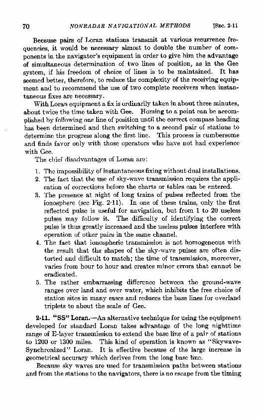
70 NONRADAR NAVIGATIONAL METHODS [SEC. 2.11
Because pairs of Loran stations transmit at various recurrence fre-
quencies, it would be necessary almost to double the number of com-ponents in the navigator’s equipment in order to give Klm the advantage
of simultaneous determination of two lines of position, as in the Geesystem, if his freedom of choice of lines is to be maintained. It ~Sseemed better, therefore, to reduce the complexity of the receiving equip-
ment and to recommend the use of two complete receivers when instan-taneous fixes are necessary.
With Loran equipment a fix is ordinarily taken in about three minutes,
about twice the time taken with Gee. Homing to a point can be accom-
plished by following one line of position until the correct compass heading
has been determined and then switching to a second pair of stations todetermine the progress along the first line. This process is cumbersome
and finds favor only with those operators who have not had experiencewith Gee.
The chief disadvantages of Loran arc:
1.2.
3.
4.
5.
The impossibility of instantaneous fixing without dual installations.The fact that the use of sky-wave transmission requires the appli-cation of corrections before the charts or tables can be entered.The presence at night of long trains of pulses reflected from theionosphere (see Fig. 2“ 11). In one of these trains, only the first
reflected pulse is useful for navigation, but from 1 to 20 uselesspulses may follow it. The difficulty of identifying the correct
pulse is thus greatly increased and the useless pulses interfere withoperation of other pairs in the same channel.The fact that ionospheric transmission is not homogeneous with
the result that the shapes of the sky-wave pulses are often dis-torted and difficult to match; the time of transmission, moreover,varies from hour to hour and creates minor errors that cannot be
eradicated.The rather embarrassing difference between the ground-waveranges over land and over water, which inhibits the free choice of
station sites in many cases and reduces the base lines for overlandtriplets to about the scale of Gee.
2.11. “SS” Loran.-An alternative technique for using the equipment
developed for standard Loran takes advantage of the long nighttimerange of E-layer transmission to extend the base line of a pair of stationsto 1200 or 1300 miles. This kind of operation is known as “ Skywave-Synchronized” Loran. It is effective because of the large increase ingeometrical accuracy which derives from the long base line.
Because sky waves are used for transmission paths between stations
and from the stations to the navigators, there is no escape from the timing
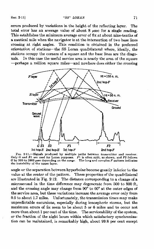
SEC. 2.11] “SS” LORAN 71
errors produced by variations in the height of the reflecting layer. Thetotal error has an average value of about 8 jLsec for a single reading.This establishes the minimum average error of fix at about nine-tenths ofa nautical mile when the navigator is at the intersection of two base linescrossing at right angles. This condition is obtained in the preferredorientation of stations—the SS Loran quadrilateral where, ideally, the
stations occupy the corners of a square and the base lines are the diago-nals. In this case the useful service area is nearly the area of the square—perhaps a million square miles—and nowhere does either the crossing
Tran
1sthopE 2nd hop-E M hopF 2ndhop-F.FIG. 2.11 .—Signals produced by multiple paths between transmitter and receiver.
Only G and El are used for Loran purposes. F1 is often split, as shown, and F2 followsG by 500 to 2000 peec depending on the range. The long and complex F pattern indicatesthe instability of the upper layer.
angle or the separation between hyperbolas become greatly inferior to thevalue at the center of the pattern. These properties of the quadrilateral
are illustrated in “Fig. 2“12. The distance corresponding to a change of amicrosecond in the time difference may degenerate from 500 to 800 ft,
and the crossing angle may change from 90° to 60° at the outer edges ofthe service area, but these variations increase the average error only from
0.9 to about 1.7 miles. Unfortunately, the transmission times may makeunpredictable excursions, especially during ionospheric storms, but themaximum errors of fix seem to be about 5 or 6 miles and to occur notmore than about 1 per cent of the time. The serviceability of the system,
or the fraction of the night hours within which satisfactory synchroniza-tion can be maintained, is remarkably high, about 99.8 per cent except
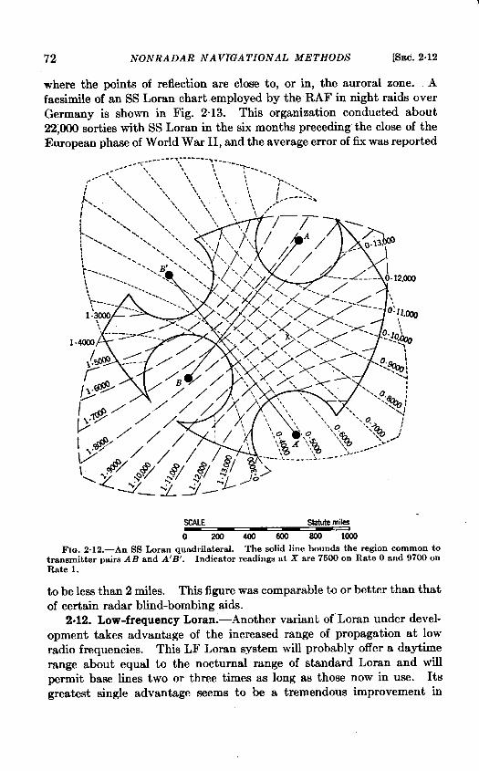
72 NONRADAR NAVIGATIONAL METHODS [SEC. 2.12
where the points of reflection are close to, or in, the auroral zone. A
facsimile of an SS Loran chart employed by the RAF in night raids over
Germany is shown in Fig. 2“13. This organization conducted about
22))00 sorties with SS Loran in the six months preceding the close of theEuropean phase of World War II, and the average error of fix waa reported
SCALE Statute miles
o 2o0400600soolm
Fm. 2.1 2.—An SS Loran quadrilateral. The solid line bounds the region common totransmitterpairs AB and A’B’. Indicator readings at X are 7500 on Rate Oand 9700 onRate 1.
to be less than 2 miles. This figure was comparable to or better than thatof certain radar blind-bombing aids.
2.12. Low-frequency Loran.-Another variant of Loran under devel-
opment takes advantage of the increased range of propagation at lowradio frequencies. This LF Loran system will probably offer a daytime
range about equal to the nocturnal range of standard Loran and willpermit base lines two or three times as long as those now in use. Its
greatest single advantage seems to be a tremendous improvement in
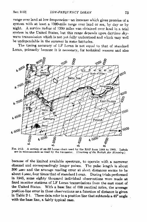
SEC, 2.12] LOW-FREQUENCY LORAN 73
range over land at low frequencies—an increase which gives promise of asystem with at least a 1000-mile range over land or sea, by day or bynight. A service radius of 1500 miles was obtained over land in a trialsystem in the United States, but this range depends upon daytime sky-wave transmission which is not yet fully understood and which may wellbe undependable in the summer in some latitudes.
The timing accuracy of LF Loran is not equal to that of standardLoran, primarily because it is necessary, for technical reasons and also
Fm. 2.13.—A section of an SS Loran chart used by the RAF from 1944 to 1945. Labelsare in microseconds as read by the navigator. (Courtesuof the&iti8h Air ~in’istr~.)
because of the limited available spectrum, to operate with a narrowerchannel and correspondingly longer pulses. The pulse length is about300 ALsecand the average reading error at short distances seems to beabout 4 psec, four times that of standard Loran. During trials performedin 1945, some eighty thousand individual observations were made atfixed monitor stations of LF Loran transmissions from the east coast ofthe United States. With a base line of 600 nautical miles, the averageposition-line error in these observations as a function of distance is givenin Table 2.1. These data refer to a position line that subtends a 45° anglewith the base line, a fairly typical case.
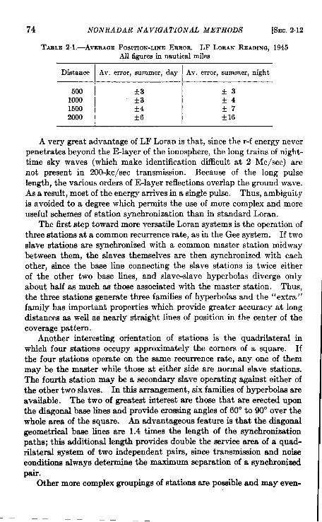
74 NONRADAR NAVIGATIONAL METHODS [SEC.2.12
TMILE 2.1.—AVERAGE POSITION-UNEERROR. LF LORAN READING,1945All figures in nautical miles
Dietance I Av. error, summer,day I Av. error, summer,night
500 *3 *31000 *3 *41500 *4 *72000 +6 +16
A very great advantage of LF Loran is that, since the r-f energy neverpenetrates beyond the E-layer of the ionosphere, the long trains of night-time sky waves (which make identification difficult at 2 Me/see) arenot present in 200-kc/sec transmission. Because of the long pulselength, the various orders of E-layer reflections overlap the ground wave.As a result, most of the energy arrives in a single pulse. Thus, ambiguityis avoided to a degree which permits the use of more complex and moreuseful schemes of station synchronization than in standard Loran.
The first step toward more versatile Loran systems is the operation ofthree stations at a common recurrence rate, as in the Gee system. If twoslave stations are synchronized with a common master station midwaybetween them, the slaves themselves are then synchronized with eachother, since the base line connecting the slave stations is twice eitherof the other two base lines, and slave-slave hyperbolas diverge onlyabout half as much as those associated with the master station. Thus,the three stations generate three families of hyperbolas and the “extra”family has important properties which provide greater accuracy at longdistances as well as nearly straight limes of position in the center of thecoverage pat tern.
Another interesting orientation of stations is the quadrilateral inwhich four stations occupy approximately the corners of a square. Ifthe four stations operate on the same recurrence rate, any one of themmay be the master while those at either side are normal slave stations.The fourth station may be a secondary slave operating against either ofthe other two slaves. In this arrangement, six families of hyperbolas areavailable. The two of greatest interest are those that are erected uponthe diagonal base lines and provide crossing angles of 60° to 90° over thewhole area of the square. An advantageous feature is that the diagonalgeometrical base lines are 1.4 times the length of the synchronizationpaths; this additional length provides double the service area of a quad-rilateral system of two independent pairs, since transmission and noiseconditions always determine the maximum separation of a synchronizedpair.
Other more complex groupings of stations are potible and may even-
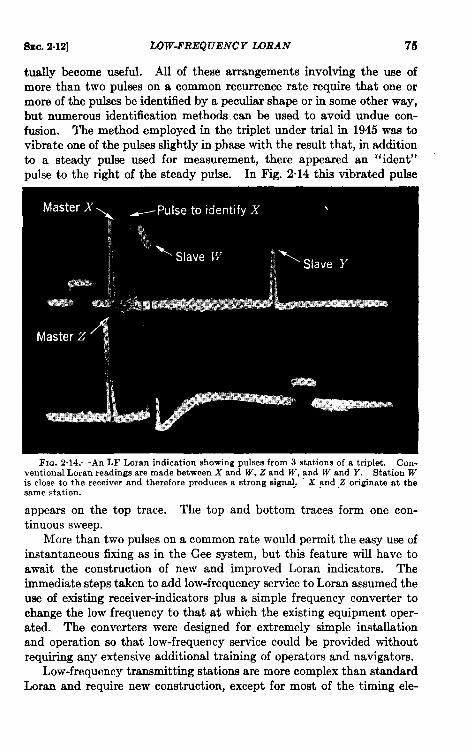
Smc.2.12] LOW-FREQUENCY LORAN 75
tually become usef~. AU of these arrangements involving the use of
more than two pulses on a common recurrence rate require that one ormore of the pulses be identified by a peculiar shape or in some other way,but numerous identification methods can be used to avoid undue con-fusion. The method employed in the triplet under trial in 1945 was tovibrate one of the pulses slightly in phase with the result that, in additionto a steady pulse used for measurement, there appeared an “ ident”pulse to the right of the steady pulse. In Fig. 2“14 this vibrated pulse
FIG. 2.14.—An LF Loran indication showing pulses from 3 stations of a triplet. Con-ventional Loran readings are made between X and W’, Z and W, and W and Y. Station Wis close to the receiver and therefore produces a strong signal.. - X and Z originate at thesame station.
appears on the top trace. The top and bottom traces form one con-tinuous sweep.
More than two pulses on a common rate would permit the easy use ofinstantaneous fixing as in the Gee system, but this feature will have to
await the construction of new and improved Loran indicators. Theimmediate steps taken to add low-frequency service to Loran assumed theuse of existing receiver-indicators plus a simple frequency converter tochange the low frequency to that at which the existing equipment oper-ated. The convefirs were designed for extremely simple installationand operation so that low-frequency service could be provided withoutrequiring any extensive additional training of operators and navigators.
Low-frequency transmitting stations are more complex than standardLoran and require new construction, except for most of the timing ele-
76 NONRADAR NAVIGATIONAL METHODS [SEC.2.13
ments, but there are so few of them that thetotal effort required to addlow-frequency operation to the present Loran system is entirely withinreason.
A version of LF Loran which may become extremely important, atleast for certain applications, is called “cycle matching”; it consists ofcomparing the phase of the r-f or i-f cycles of apairof pulses rather thanof comparing the envelopes of the two pulses. Equipment for thistechnique is still in such an early stage of laboratory development that acritical evaluation is not yet possible; it seems reasonable, however, toexpect that measurements may be made to 0.1 ~sec over ground-waveranges. The facility with which such readings can be taken is as yetunknown, but it is probably safe to predict that after a difficult develop-ment program cycle matching can provide accuracies equal to those ofH-systems, at ranges of 600to 800 miles. Preliminary testsin August1945 gave an average position-line error of 160 ft for observations onstations 750 miles distant.
2.13. Decca.—Decca is the name commonly applied to a low-fre-quency continuous-wave hyperbolic system, officially designated “ QM,”that has been under test and operation by the British Admiralty for someyears. As in other hyperbolic systems, at least three stations (two pairs)are necessary to provide fixing cover. The master station transmits atthe basic radio frequency of the system while the slave in each pairradiates at a different radio frequency simply related to that of the master,the ratio being 3t02, or4to 3, etc. Each slave monitors the master,maintaining its own emissions at its assigned frequency but with phaserigidly related to that of the master. The family of hyperbolic lines thusare lines of constant phase difference.
The navigator’s equipment consists of a receiver channel for eachstation (three in all for fixing), suitable multiplying and phase-comparingcircuits, and two phase-indicating meters (similar to watt-hour meters).Let us assume the master frequency to be 90 kc/see, that of one slave tobe 120 kc/see and that of the other slave to be 135 kc/see. The equip-ment, by means of frequency multipliers, changes the frequencies of themaster and first slave to the common multiple of 360 kc/see, and displaysthe phase difference on the indicating meter; this furnishes informationon one line of position.
For the second slave and second line of position the phase differenceis examined at a frequency of 270 kc/see. The operation is whollydifferential; the coordinates of the point of departure must be set into theequipment manually at the beginning of every continuous run. A con-stant phase reading indicates that a hyperbolic course is being followed,and changes of phase may be summed up when cutting across hyperbolic“lanes.” The wavelengths used are about a mile or greater. The read-
SEC. 2.14] ACCURACY AND RANGE OF VARIOUS SYSTEMS 77
ing precision has been quoted variously from & of a wavelength to &of a wavelength.
The Decca system in its present form is highly ambiguous becausethere can be no identification of a cycle. Therefore, although a greatmany lines of position are available to the navigator, successful inter-pretation of the data obtained depends upon two factors, First, thepoint of departure of the vessel must be known, and second, the equip-ment must be operated continuously. Ambiguity can be reduced as faras desired by modulating the radio frequency with a lower envelopefrequency that gives coarser identification of the hyperbolic lines. Thistechnique apparently makes the receiving equipment prohibitivelycomplex.
Decca has two other defects that militate against its extensive use.One is its somewhat extravagant use of the radio spectrum. Because adifferent frequency is required for each station, the number of frequenciesrequired to cover a large area would be prohibitive. A pulsed systemcovering an equal area would utilize only one spot in the spectrum andrequire a smaller net channel width.
The second, and more serious, defect of Decca is that interferingcontinuous waves can distort the readings almost without limit withoutthe navigator’s being aware of it. An extreme example is the inter-ference produced by sky-wave transmission, which is often present at thefrequencies employed for Decca. It prevents the use of base lines morethan 100 miles long, and limits the useful service radius to perhaps aslittle as 200 miles.
2.14. Accuracy and Range of Various Systems.—A consideration ofthe factors which affect the timing accuracy of pulsed systems indicatesthat a Loran system (a system in which the pulses are equalized andsuperimposed) ideally should yield matches which are accurate to abouthalf a wavelength. This accuracy corresponds to a minimum error ofline of position of a quarter wavelength, or 125 ft at the frequency usedfor standard Loran. Actually, the minimum error in standard Loran isabout 500 ft; this increase is due partly to the use of pulses about twicethe minimum size and partly to the use of reading techniques that are notas precise as could be desired.
The accuracy of Loran in the ground-wave service area could nodoubt be quadrupled by the use of shorter pulses and indicators withmore stable circuits and more closely spaced families of marker pips.These changes, however, would not enhance the sky-wave service, whichcontributes a large part of the usefulness of the system, because in thatcase the accuracy is controlled by propagational variations that seldompermit an average error of less than 2 psec, which is twice the currentreading error.
78 NONRADAR NAVIGATIONAL METHODS [SEC.2.14
Gee pulses are not equalized in amplitude or superimposed. Ameasurement, therefore, is good only to about one tenth of the pulselength. Inthe Geesystem, thepractical average error is about 100yd;the “theoretical’’e rrorisa bout one fourth as great, oreven less at thehigher frequencies. As in Loran, the departure from the optimum isaccounted for partly by the use of long pulses to reduce the spectrumspace required and partly by a certain crudity in the indicating equipmentfor the sake of simplicity.
For LF Loran the same analysis leads to an estimate of average errorsof a quarter mile in the best areas. Although this figure may actually beattained now at short distances, propagational factors as well as geometr-ical ones will probably operate to increase these errors over a large partof the service area.
For Decca or other phase-comparison systems, it seems reasonablethat a precision of 1° of phase should be attained, although neitherDecca nor cycle-matching LF Loran have yet reached that accuracy inpractice. Even the present precision of about 1 per cent of a wavelength,however, is extremely interesting in comparison with pulse envelopemethods.
Transmission ranges and service areas also depend primarily onfrequency, and the lower the frequency the better. The reliable rangethroughout the microwave region is little more than the optical range.Even the ranges obtained in the uhf band are not more than about one andone-half times the optical range. This often results in good cover forhigh-flying aircraft, as in the Gee system, but the distances usable at thesurface of the earth are discouraging from the point of view of navigation.
As the frequencies decrease through the high- and medium-frequencyregions, ground-wave ranges increase and the differential in signalstrength observed at high and low altitudes grows smaller, especially oversea water. The propagation of signals as the frequency is decreased isno longer simple because of the complex structures of multiple sky-wavereflections that vary tremendously with the time of day. Furthermore,at the higher frequencies the behavior of sky-wave reflections is extremelyunpredictable.
These sky-wave phenomena become simpler and more predictable inthe lower part of the medium-frequency range, but only at low frequen-cies is there such a degree of stability that sky waves can be used withoutconfusion. At very low frequencies, propagation over thousands of milesis easy and reliable, but wide-band antenna systems are not availablebecause the required size is prohibitive.
As long as current techniques prevail, therefore, pulse methods cannotbe expected to operate at these frequencies. At present it seems that 100to 150 kc/see is about the lower limit for pulse systems. At these fre-
Sw. 2,15] A UTOMA TIC DATA ANALYSIS 79
quencies ranges of 1500 miles should be easily obtained over land or seaand at any altitude. Either pulse or continuous-wave systems may beused at these frequencies, although the pulse systems will require largerand more expensive antenna structures. If reliable ranges greater thanabout 1500 miles are needed, continuou~wave systems operating at verylow frequencies must be used. The alternative is to use pulse systemswith very long pulses and relatively low accuracy.
All of these considerations lead to the conclusion that there are,theoretically, two infinite families of hyperbolic navigation systems, thepulsed and the continuous-wave methods, and that for each method thechoice of frequency establishes the desired compromise between range andaccuracy. Continuous-wave systems have inherently greater precisionhut are so ambiguous that they are of interest only at the low-frequencyend of the spectrum. Pulse systems, on the other hand, may be usefulat any radio frequencies except the very lowest, but they suffer fromlimited range at higher frequencies, from sky-wave interference andambiguity at middle frequencies, and from limited accuracy at the lowfrequencies.
Nevertheless, the choice among the many possibilities is easy. In apermanent navigation system, the ambiguities inherent in the continuous-wave method and in pulse methods in the high-frequency range areintolerable. Therefore, the choice lies between low-frequency and uhfpulse methods. Of these, the uhf method is unsatisfactory because ofits very short ranges at the surface of the earth. A secondary factor ofmarked economic importance is the far greater number of high-frequencystations required to cover a given area. A low-frequency Loran system,on the other hand, should give fixes to within 5 miles or so over tremen-dous areas and errors well under a mile in certain areas. For mostpurposes this accuracy is sufficient. If much greater accuracy is requiredthere are two alternatives whose relative merits need to be investigated:cycle matching in LF Loran, and local-approach uhf chains supplement-ing a low-frequency general navigation system and receivable with thesame equipment.
2.15. Automatic Data Analysis.-Anyone familiar with Gee or Loranequipment can readily see that it would not be difficult to perform all ofthe set manipulations automatically. There is no insuperable technicalproblem in producing a receiver which will automatically present, forexample, the Loran readings on two lines of position on a pair of dialcounters. During the war, however, completely automatic receiverswere not needed, but when hyperbolic navigation is applied to commercialtransportation a position-determining set that operates continuously willbe desirable. Like the chronometer in the chart room, it will be in con-stant use; the navigator should be able to look at it whenever he wishes to
80 NONRADAR NAVIGATIONAL METHODS [SEC.2.15
know his position. There are a great many ways in which such automaticsets can be built. Most of them may be so complicated, however, thatthe navigator would be properly skeptical of their reliability.
The most common suggestion for a device of this kind is to have anattachment to the indicator which would automatically present latitudeand longitude directly to the observer. This is a natural but misguidedproposal because there is little that is inherently more desirable in latitudeand longitude than there is in Loran coordinates. The two things that anavigator always wants to know are the distance and direction to one orto several points.
Another suggestion is to use a black box containing a number of pushbuttons and a pair of visible counter mechanisms. A navigator wouldonly have to push the button marked “ Bermuda,” for instance—where-upon the counters would spin and stop so that he could read ‘‘ distance,342 miles; course, 1140.” Such a device, however fine a toy it might be,fails because the navigator should not be satisfied unless he is told hisrelation to a great many different places. Once he obtained this informa-tion, either with the black box or the latitude-longitude indicator, hewould then have to plot his position on a chart before he could understandthe interrelations between his position and those of all other significantpoints.
Obviously, the only really effective automatic aid to navigation willplot the position of the vessel continuously. It should leave a permanenttrack on a chart so that the navigator can see at a glance his currentposition in relation to all other points on the chart, and also can have thehistory of his voyage presented to him in graphic form.
The desirability of such an instrument will be obvious to the salesmanagers of our larger electronic corporations. They will probably seeto it that the necessary time is spent to develop and produce a practicabledevice. The only prerequisites are that ground stations must be inoperation to provide the necessary coverage, and that the control of theground stations must be in responsible hands.
It is worth while here to point out a single concept which, althoughit violates sea-going tradition, may have some influence by virtue of itssimplicity. In any Loran indicator, there is sure to be a shaft whoserotation is more or less linearly proportional to the Loran reading.This shaft may be connected to a pen through a mechanism such that thelateral position of the pen also bears a linear relation to the Loran read-ing. A second shaft from the same, or a second, indicator may be con-nected so that a rotation of that shaft in accordance with a second Loranreading produces a linear motion of the pen at an angle to the first motion.With this arrangement, any pair of Loran readings which defines a pointon the surface of the earth also defines a position of the penpoint on a
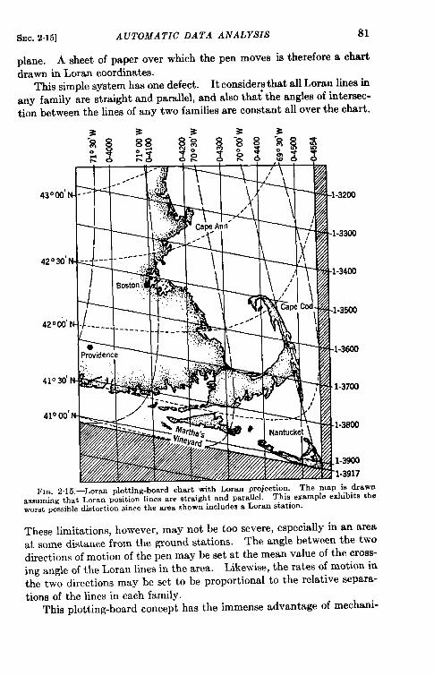
SEC. 215] A UTOMA TIC DATA ANALYSIS 81
plane. A sheet of paper over which the pen moves is therefore a chartdrawn in Loran coordinates.
This simple system has one defect. It considerp that all Loran lines in
any family are straight and parallel, and also that the angles of intersec-tion between the lines of any two families are constant all over the chart.
I I I/--
,, \ I ‘t \ I
42030’wK-i
IF’rovidw ~ ‘.:-.‘.,,.
.
Fm. 2.15.—Loran plotting-board chart with Loran projection. The yap is dr~ssuming that Loran position lines are straight and parallel. T,hi~e~
, .,.:.-
worst possible distortion since tbe area shown includes a Loran station.
~wnthe
These limitations, however, may not be too severe, especially in an areaat some distance from the ground stations. The angle between the two
directions of motion of the pen may be set at the mean value of the cross-ing angle of the Loran lines in the area. Likewise, the rates of motion in
the two directions may be set to be proportional to the relative separa-tions of the lines in each family.
This plotting-board concept has the immense advantage of mechani-
82 NONRADAR NAVIGATIONAL METHODS ~EC. 2.11
caland electrical simplicity. Inmanycases, ifthearea onachart isnottoo great and if the ground stations themselves are not in the chartedarea, the distortions encountered in drawing such a chart in Loran coordi-nates are no greater tian those involved in many other projections.
Experiments were conducted with SS Loran using a plotting board ofthis sort. An ordinary Lambert chart was used to cover an area whoseside was 150 miles, about a sixth of the length of the base liies, andthe Loran lines were sufficiently straight and uniform to ensure that theerrors due to the assumptions mentioned above were no larger than theerrors inherent in SS Loran. The presentation described in the lastparagraph was also tried and flown for standard Loran, with good results.A section of the Loran projection so used is given in Fig. 2.15.
2.16. Automatic Piloting.-Mentally it is only a very short step, andmechanically not a long one, from automatic presentation of position ona map to connecting the map and the rudder of a vessel so that a pre-determined track may be followed automatically. The means are easyto visualize and are already at hand. Only incentive and time arerequired; here, again, commercial enterprise may be relied upon to bringa family of such devices into being.
One variant from past experience with direction-finding must bepointed out. When a direction-finding system is used, any change ofcourse is immediately indicated and measured so that a correction maybe made instantaneously if the change is accidental. When a hyperbolicsystem is used, however, a change of course does not lead to any change ofindication until after the new course has been held for some finite time.That is, the hyperbolic system gives an indication of position, not ofdh-ection, and the indication does not depend at all upon the attitude ofthe vehicle. This is an important and valuable point. It makes naviga-tion independent of currents in sea or air because, to reiterate, all coursesand speeds directly derived from hyperbolic systems are ground coursesand ground speeds.
A simple right-left indicator to show a pilot whether he is to the rightor left of the Loran line he wishes to follow, or even how far to the right orleft, will not be very successful in helping him follow the line becausethere is no appreciable relation between the indications on the meter andthe course that the pilot should follow. Thus, if the meter shows him tobe to the left of hk desired track, he tends to turn more and more to theright, until he crosses the line at a large angle, and has to repeat the processin reverse. The net result is a zigzag track which, although it passesnearly over the objective, wastes large quantities of time, fuel, and thepilot’s energy on the way.
Theoretically, this difficulty could be removed if the pilot would studythe behavior of the right-left meter in enough detail to understand both
&Jc.2.16] AUTOMATIC PILOTING S3
the degree of his displacement from the line and his rate of progreeatoward or away from it. With a knowledge of both these factors, hecould return to the desired track by a gentle change of course and couldstay on it with only small excursions. The pilot is, however, too occupiedwith the business of piloting to enter into such a study, so it is necessaryto advance the equipment another stage and present to him both hisrate of approach and the distance from the line he wishes to follow. Hemay be shown, for example, two meter readings, as is now done in Shoran(Sec. 7“13). One of these might tell him that he is 1000 ft to the left ofthe line, and the other that he is approaching the line at 50 ft/sec. It isclear immediately that, if he continues on the same course he has beenholding, he will reach the line in 20 sec and that, if he wishes to comesmoothly onto the line, he should begin to change course to the left.This conclusion is, of course, the opposite of that derived from the simpleright-left indicator and shows clearly the defect in that presentation.
Within certain limits, it is possible to combine automatically thefactors of displacement and rate of change of displacement. The pilot,therefore, would not need the two meters mentioned in the precedingparagraph, but could use a single indicator calibrated in terms of theappropriate course correction, such as “two degrees to the left. ” Theonly defect in this instrument would be a time constant dependent uponthe time required to analyze the rate of approach to the track, requiringthe pilot to learn not to make a second correction too soon after the first.
This difficulty would vanish if the meter indication, instead of beingpresented to a human pilot, were connected to a gyro-controlled automaticpilot. In that case the linkage to the automatic pilot could easily begiven the appropriate time constant to prevent overcorrection.
The design suggested above is the simple and natural way to build adevice that will automatically follow a Loran line. This is worthwhile because there is always a line passing through any target in aLoran service area, but it falls far short of the really desirable solution.The most important requisite of automatic equipment, like the humanpilot-navigator combination, is the ability to proceed by a simple andreasonably direct course from wherever the vessel happens to be to wher-ever it should go.
This ability can stem only from simultaneous examination of twofamilies of hyperbolas. There are many ways to make this examination,just as there are many ways to make a plotting board. One of them is sovery simple that it should be mentioned here .“
Assume a Loran receiver capable of following automatically two Loranreadings in two families of hyperbolic lines. The shaft rotation corres-ponding to either of these readings could be connected through thedisplacement-and-rate device mentioned above to the rudder of the vessel.
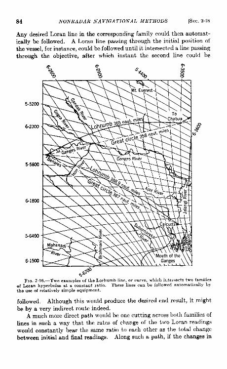
84 NONRADAR NAVIGATIONAL METHODS [SEC.2.16
Any desired Loran line in the corresponding family could then automat-ically be followed. A Loran line passing through the initial position ofthe vessel, for instance, could be followed until it intersected a line passingthrough the objective, after which instant the second line could be
5-5200
6-2300
5-5800
6-1800
5-6400
6-1500
#’$ “
FIG. Z.16.—TWOexamples of the Lorhumb line, or curve, which intersects two familiesof Loran hyperbolas at a constant ratio. These lines can be followed automatically bythe use of relatively simple equipment.
followed. Although this would produce the desired end result, it mightbe by a very indirect route indeed.
A much more direct path would be one cutting across both families oflines in such a way that the rates of change of the two Loran readingswould constantly bear the same ratio to each other as the total changebetween initial and final readings. Along such a path, if the changes in
SEC. 2.16] AUTOMATIC PIWTING 85
one Loran reading were followed automatically while the time differencefor the second set of lines was constrained to vary in the designated ratioto the variation in the first reading, then the second pair of pulses, onceset to coincidence, would remain so. The steering mechanism might beso controlled by the second pair of pulses that it would maintain thecoincidence, thus directing the vessel along the chosen path.
For example, if the readings were 3500 at the initial point and 27oO atthe objective on the first Loran pair, and 1400 and 1800 on the secondpair, the linkage between the indications would be set at – & Thevessel would then follow such a track that it would successively passthrough points whose Loran coordinates were (3400, 1450) (3300, 1500). . . (2800, 1750) to the objective at (2700, 1800). The track wouldbe almost direct unless it passed very near one of the transmitting sta-tions. In fact, the track would differ from a great circle only in propor-tion as the Loran lines differed from being straight and parallel.
Figure 2.16 shows two lines of this sort drawn upon a Loran chart ofpart of India. The great circle from Calcutta to Benare~ is shown as adashed line while the proposed curve, or “ Lorhumb line,” which crossesthe East-West lines at two-thirds the rate that it crosses the North-Southlines, is shown as a solid line. For the great-circle track, the shortestdistance is 387 miles. The Lorhumb line is 1.9 miles, or 0.5 per cent,longer.
A second Lorhumb line is drawn between Benares and point Q whichis about halfway from Benares to Chabua, off to the right of the map inFig. 2.16. Here the geometry of the Loran limes is less favorable so thatthe proposed course is 7.0 miles, or 2.0 per cent, longer than the great-circle dktsmce of 358 miles. If an attempt were made to span the dis-tance from Benares to Chabua with a single Lorhumb line, the excessdistance would be about 30 miles, or 4 per cent, of the total distance.
This sort of path has been called the “Lorhumb line” because it is t heexact parallel, in hyperbolic navigation, of the rhumb line in Mercatorsailing. Various Lorhumb lines might be connected by the navigator toform an approximate great circle or any other desired path. Devicesutilizing this principle will probably be adequate for all navigationalpurposes (as distinguished from problems of pilotage) and will presumablybe simpler than others which, through more complete analysis of the exactforms of the hyperbolic lines, could follow slightly more direct paths.The advantages of the design are so obvious that devices that embodythis principle may be expected to be ready for experimental operation assoon as engineering talent is available.

PART II
AIRBORNE RADAR

CHAPTER 3
CHARACTERISTICS OF AIRBORNE RADAR
BY D. L. HAGLER, C. F. J, OVERHAGE, J. H. BUCK, J. J. HIBBERT,
G. A. GARRETT, H. FAHNESTOCK, JR., AND T. H. WATERMAN
INTRODUCTION
The purpose of this chapter is twofold-first, to present to the readera picture of what an observer sees on his airborne radar indicator; andsecond, to show how this information may be interpreted and used as anaid to navigation and pilotage.
The most elementary method of air navigation consists of flying fromlandmark to landmark with little or no reference to instruments of anykind. This is usually supplemented by some form of dead reckoning toovercome poor visibility. The radar equipment, essentially, enables oneto fly a similar reference-point course at night or through overcast and touse reference points at a much greater distance than is possible visually.
The scale of usable reference points in radar, of course, is different.Visually, roads, railroads, villages, parks, lakes, and rivers, usually withina 10-mile radius, are most useful for reference. On the radar indicatoronly towns, cities, larger lakes, and rivers are visible in recognizableforms; they can, however, be identified 20 to 50 miles away. When thereference points are not easy to identify individually, the pilot may findhis position by using a map with his radar indicator to identify a com-bination of reference points.
In visual pilotage, the distance to an object and its angular positionwith respect to the airplane must be estimated. This is relatively easyto do at low altitudes, but at high altitudes, distances are extremely hardto judge, even on a clear day. With radar pilotage, guesswork is elimi-nated because range marks and an azimuth scale giving adequate accu-racies can be superimposed on the picture.
3.1. Features Revealed by Radar Mapping. ‘When presented on aPPI, the basic range, azimuth, and signal strength information obtainedby radar form a radar map of the territory over which the airplane isflying. This map, which displays the relative amount of energy reflectedback to the antenna by the individual elements of the surroundingterrain, has a direct resemblance to its topographical characteristics.
ISections3.1 and 3.2 by D. L. Haglerand C. F. J. Overhage.89
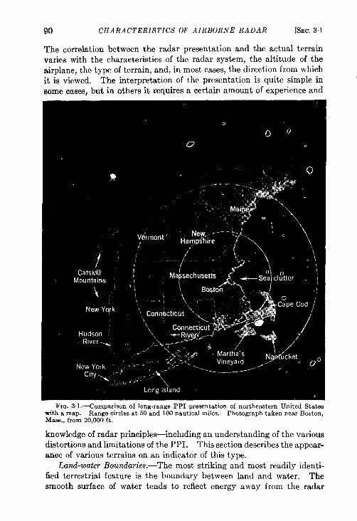
90 CHARACTERISTICS OF AIRBORNE RADAR [SEC.3.I
The correlation between the radar presentation and the actual terrainvaries with the characteristics of the radar system, the altitude of theairplane, the type of terrain, and, in most cases, the direction from whichit is viewed. The interpretation of the presentation is quite simple insome cases, but in others it requires a certain amount of experience and
Fm. 3.1 .—Comparison of long-range PPI presentation of northeastern United Stateswith a map. Range circles at 50 and 100 nautical miles. Photograph taken near Boston,Mass., from 20,000 ft.
knowledge of radar principles-including an understanding of the variousdistortions and limitations of the PPI. This section describes the appear-ance of various terrains on an indicator of this type.
Land-water Boundaries.-The most striking and most readily identi-fied terrestrial feature is the boundary between land and water. Thesmooth surface of water tends to reflect energy away from the radar
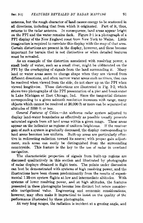
SEC.31] FEATURES REVEALED BY RADAR MAPPING 91
antenna, but therough character oflandcauses energy to be scattered inall directions, including that from which it originated. Part of it, thus,returns to the radar antenna. In consequence, land areas appear brighton the PPI and the water remains dark. Figure 3.1 is a photograph of aPPI display of the New England coast from New York to Maine. Littleimagination is required to correlate this display with the map of that area.Certain distortions are present in the display, however, and these becomeimportant for terrain that is not distinctive or when detailed featuresmust be revealed.
As an example of the distortion associated with resolving power, asmall body of water, such as a small river, might be obliterated on thePPI by the overlapping of signals from the land surrounding it. Manyland or water areas seem to change shape when they are viewed fromdifferent directions, and often narrow water areas such as rivers, that canbe resolved when viewed from the side, do not show up on the PPI whenviewed lengthwise. These distortions are illustrated in Fig. 3.2, whichshows two photographs of the PPI presentation of a pier and breakwaterin Lake Michigan at East Chicago, Ind. Since the tangential distancecorresponding to a given azimuth resolution increases with range, manyobjects which cannot be resolved at 20,000 ft or more can be separated ataltitudes of 5000 ft or less.
General Features of Cities.—An airborne radar system adjusted todisplay land-water boundaries as effectively as possible usually presentssaturated signals from all land areas within a given range. These areasappear on the indicator as regions of uniform brightness. If the receivergain of such a system is gradually decreased, the display corresponding toland areas becomes less uniform. Built-up areas are particularly effec-tive in redirecting radiation toward its source; with proper gain adjust-ment, such areas can easily be distinguished from the surroundingcountryside. This feature is the key to the use of radar in overlandnavigation.
The characteristic properties of signals from built-up regions ared~cussed qualitatively in this section and illustrated by photographsof radar displays obtained in flight tests. The points under discussioncan best be demonstrated with systems of high resolving power, and theillustrations have been chosen predominantly from the results of experi-mental 1.25-cm system flights at low and intermediate altitudes. Withsystems of lower resolving power, and at high altitudes, the featurespresented in these photographs become less distinct but retain consider-able navigational value. Engineering and economic considerations,however, may often make it impractical to insist on the quality of theperformance illustrated by these photographs.
At very long ranges, the radiation is incident at a grazing angle, and
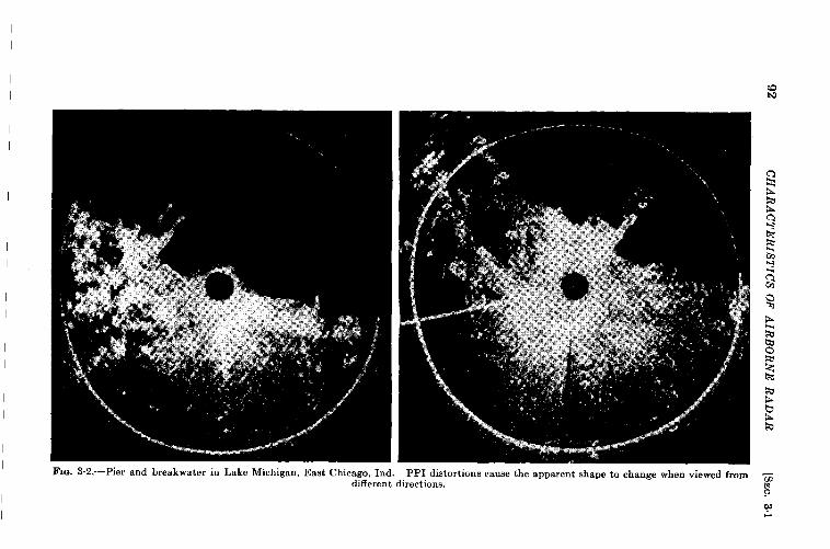
92C
HA
RA
CT
ER
ISTIC
SO
FA
IRB
OR
NE
RA
DA
R[S
EC
.31
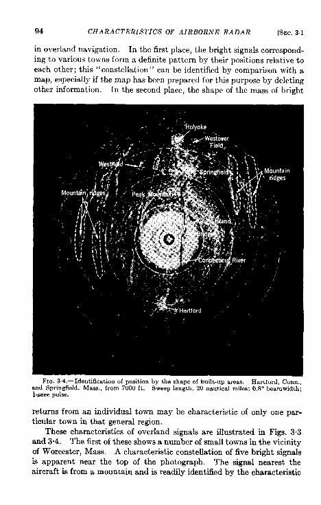
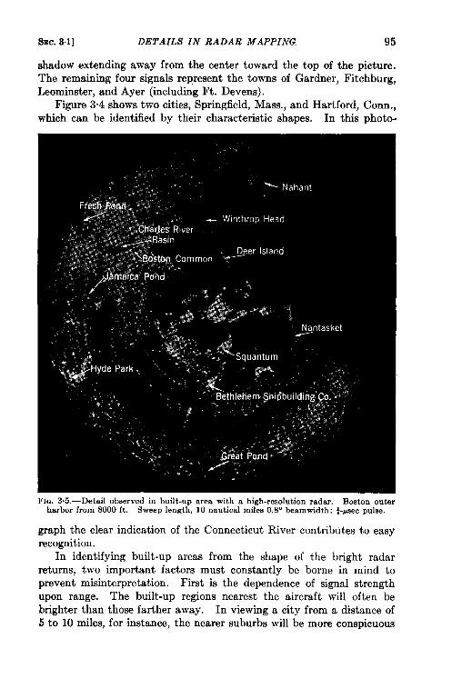
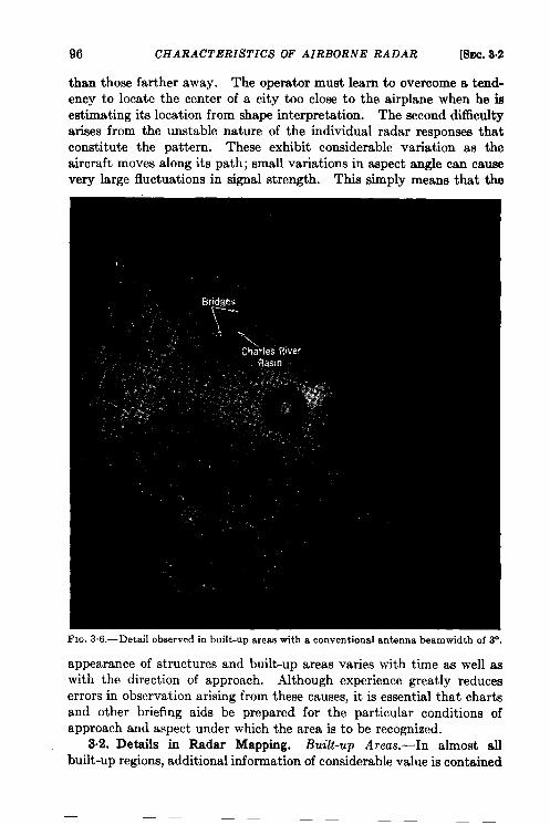
96 CHARACTERISTICS OF AIRBORNE RADAR [SEC..32
than those farther away. Theoperator must learn toovercome a tend-ency to locate the center of a city too close to the airplane when he isestimating its location from shape interpretation. The second difficultyarises from the unstable nature of the individual radar responses thatconstitute the pattern. These exhibit considerable variation as theaircraft moves along its path; small variations in aspect angle can causevery large fluctuations in signal strength. This simply means that the
Fm. 3.6.—Detai1 observed in buift-up areaewith a conventional antenna beamwidth of 3“.
appearance of structures and built-up areas varies with time as well aswith the direction of approach. Although experience greatly reduceserrors in observation arising from these causes, it is essential that chartsand other briefing aids be prepared for the particular conditions ofapproach and aspect under which the area is to be recognized.
3.2. Details in Radar Mapping. Built-up Areas.—In almost allbuilt-up regions, additional information of considerable value is contained
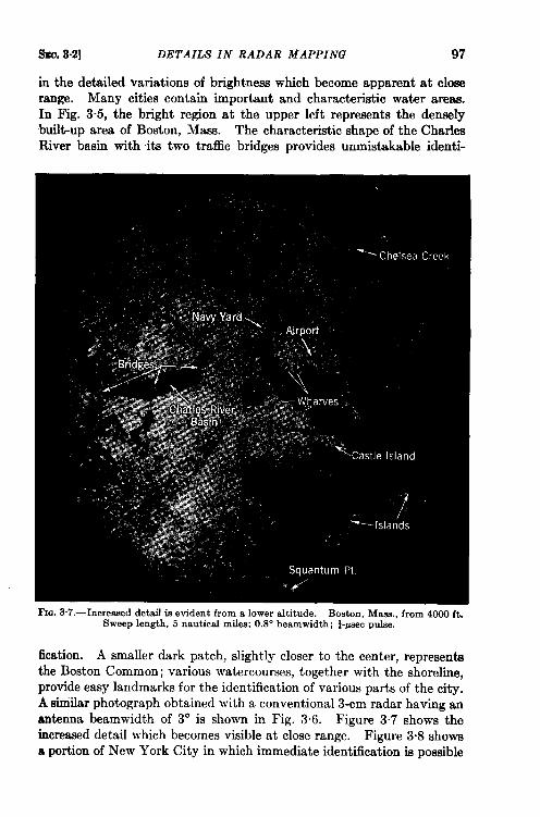
snc. 8.2] DETAILS IN RADAR MAPPING 97
in the detailed variations of brightness which become apparent at closerange. Many cities contain important and characteristic water areas.In Fig. 3.5, the bright region at the upper left represents the denselybuilt-up area of Boston, Maw. The characteristic shape of the CharlesRiver basin with its two trafic bridges provides unmistakable identi-
Fm. 3.7.—Increaaed detaif is evident from a lower altitude. Boston, Maes., from 4000 ft.Sweep length, 5 nautical miles; 0.8” beamwidth; }-psec pulse.
fication. A smaller dark patch, slightly closer to the center, representsthe Boston Common; various watercourses, together with the shoreline,provide easy landmarks for the identification of various parts of the city.A siniilar photograph obtained with a conventional 3-cm radar having anantenna beamwidth of 3° is shown in Fig. 3.6. Figure 3.7 shows theincreased detail which becomes visible at close range. Figure 3.8 showsa portion of New York City in which immediate identification is possible
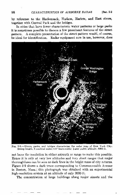
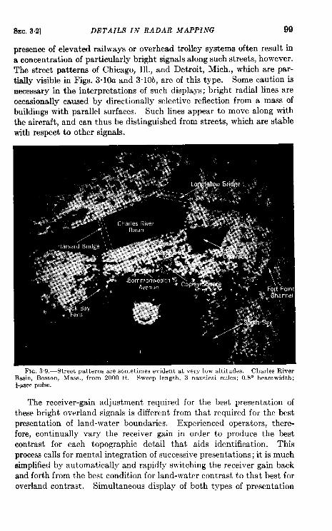
%c. 32] DETAILS IN RADAR MAPPiNG 99
presence of elevated railways or overhead trolley systems often result ina concentration of particularly bright signals along such streets, however.The street patterns of Chicago, Ill., and Detroit, Mich., which are par-tially visible in Figs. 3“10a and 3“10b, are of this type. Some caution isnecessary in the interpretations of such displays; bright radial lines areoccasionally caused by directionally selective reflection from a mass ofbuildings with parallel surfaces. Such lines appear to move along withthe aircraft, and can thus be distinguished from streets, which are stablewith respect to other signals.
The receiver-gain adjustment required for the best presentation ofthese bright overland signals is different from that required for the bestpresentation of land-water boundaries. Experienced operators, there-fore, continually vary the receiver gain in order to produce the bestcontrast for each topographic detail that aids identification. Thisprocess calls for mental integration of successive presentations; it is muchsimplified by automatically and rapidly switching the receiver gain backand forth from the best condition for land-water contrast to that best foroverland contrast. Simultaneous display of both types of presentation
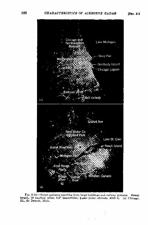
loo CHARACTERISTICS OF AIR”BORNE RADAR [SEC.3.2
Fm. 3.10.—Street patterns resulting from large buildings and railway systems. Sweeplength, 10 nautical miles; 0.8° beamwidth; $Asec pulse; altitude, 4000 ft. (a) Chicago,IU., (b) Detroit, Mich.
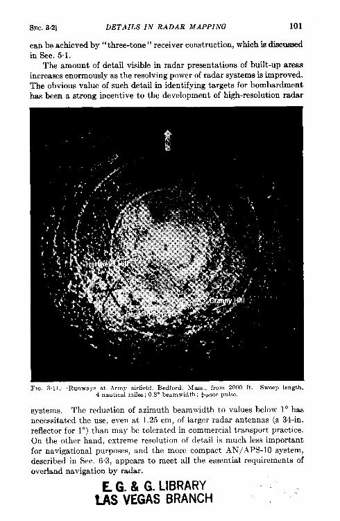
SEC. 3.2] DETAILS IN RADAR MAPPING 101
crm be achieved by” three-tone” receiver construction, which is discussedin Sec. 5.1.
The amount of detail visible in radar presentations of built-up areasincreases enormously as the resolving power of radar systems is improved.The obvious value of such detail in identifying targets for bombardmenthas been a strong incentive to the development of high-resolution radar
FIG. 3.11,—Runways at Army airfield, Bedford, Mass., from 2000 ft. Sweep length,4 nautical miles; 0,8° beamwidth; &psec pulse.
systems. The reduction of azimuth beamwidth to values below 1° hasnecessitated the use, even at 1.25 cm, of larger radar antennas (a 34-in.reflector for 10, than may be tolerated in commercial transport practice.On the other hand, extreme resolution of detail is much less importantfor navigational purposes, and the more compact AIN/APS-10 system,described in Sec. 63, appears to meet all the essential requirements ofoverland navigation by radar.
E G. & G. LIBRARYMS VEGAS f3FtAi’W-i ‘ . :
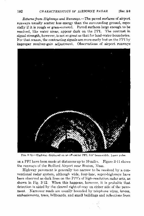
102 CHARACTERISTICS OF AIRBORNE RADAR [SEC.3.2
Returns from Highways and Runways.—The paved surfaces of airportrunways usually scatter less energy than the surrounding ground, espe-cially if it is rough or grass-covered. Paved surfaws large enough to beresolved, like water areas, appear dark on the PPI. The contrast insignal strength, however, is not so great as that for land-water boundaries.For that reason, the contrasting signals are more easily lost on the PPI byimproper receiver-gain adjustment. Observations of airport runways
FIG. 3.12.—Highway displayed on an off-center PPI, O.SObeamwidth, &psec pulse.
on a PPI have been made at distances up to 10 miles. Figure 3.11 showsthe runways of the Bedford Airport near Boston, Mass.
Highway pavement is generally too narrow to be resolved by a con-vent ional radar system, although wide, four-lane, super-highways havebeen observed as dark lines on the PPI’s of high-resolution radar sets, asshown in Fig. 3.12. When this happens, however, it is probable thatdetection is aided by the cleared right-of-way on either side of the pave-ment. Narrower roads are usually bounded by telephone wires, fences,embankments, trees, billboards, and small buildings and reflections from
. .
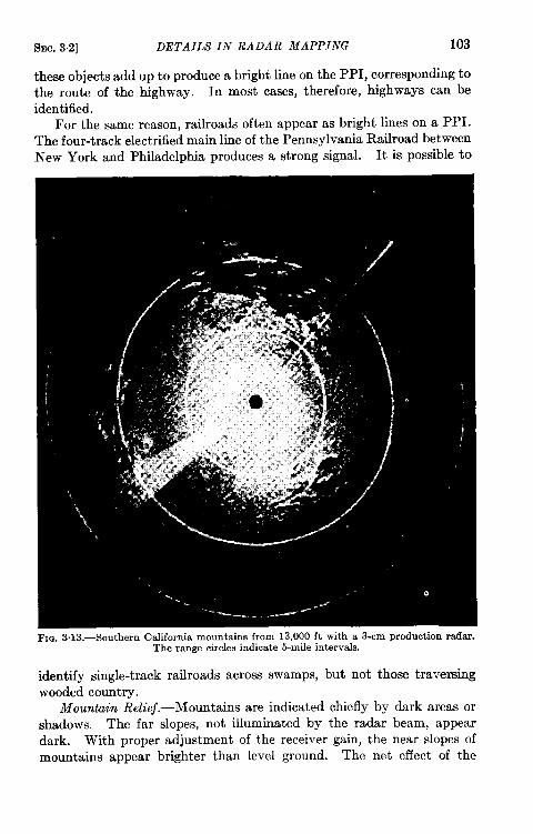
SEC.3.2] DETAILS IN RA DAR MAPPING 103
these objects add up to produce a bright line on the PPI, corresponding tothe route of the highway. In most cases, therefore, highways can beidentified.
For the same reason, railroads often appear as bright lines on a PPI.The four-track electrified main line of the Pennsylvania Railroad betweenNew York and Philadelphia produces a strong signal. It is possible to
FIG. 3.13.—Southern California mountains from 13,000 ft with a 3-cm production radar.The range circles indicate 5-mile intervals.
identify single-track railroads across swamps, but not those traversingwooded country.
Mountain Relief.—Mountains are indicated chiefly by dark areas orshadows. The far slopes, not illuminated by the radar beam, appeardark. With proper adjustment of the receiver gain, the near slopes ofmountains appear brighter than level ground. The net effect of the
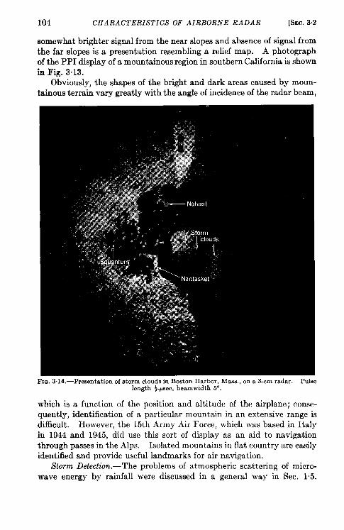
Snc. 34] MEASUREMENT OF DRIFT AND GROUND SPEED 105
Signals from storms have been observed on airborne radar sets at rangesaegreatas50miles, Theydiffer fromthose ofmostother objects becausethey have less distinct boundaries, usually change in shape and size, andpersist even when the antenna is tilted upward and the ground signalsdieappear. Figure 3.14 shows a storm area on a PPI display of Bostonharbor. The characteristic appearance of the storm may be comparedwith the sharp boundary between land and water. Note that the radarreturn from the central portion of the storm area is strong enough toobscure the return from ships that might be located on the ocean below.
3.3. The Operator.-The two previous sections described the infor-mation that can be obtained by observation of the PPI of an airborneradar. In this section the necessary qualifications of the radar operatorare discussed.
It is easy to operate an airborne radar set and to obtain signals on thePPI, but it is difficult both to operate the equipment intelligently and tointerpret the picture correctly. The operator must be trained to look atthe PPI as we ordinarily look at a photograph. It is equivalent to ana-lyzing an X-ray in which bright blobs must be recognized as towns andcities, dark spots as lakes or mountain shadows. This interpretive abilitycomes only with training and practice.
A poorly trained operator gets land-water contrast but n.o detail of theland even with a high-resolution set. At least 25 to 50 hours of actualoperating experience are required to learn the proper technique to makerailroads, buildings, etc. stand out clearly. Only then can the operatorproperly and completely interpret his oscilloscope picture.
Not all of the required training need be done in the air. In fact,htter initial training can be done on a supersonic trainer on the ground,away from the noise and complications of flying. Like the Link trainer,the supersonic radar trainer gives the operator the fundamental ideas ofradar operation, teaches him the initial knob twisting, and enables himto practice measurements of ground speed and drift at any time. Teach-ing is infinitely easier on a ground trainer than in an airplane because theoperator’s errors and progress can be checked directly.
3.4. Measurement of Drift and Ground Speed.z ConventionalMethods.—Navigation of an airplane can be compared with the problemof determining the angle at which a canoe should be headed upstream sothat it will travel in a straight line to a point directly across the river.This angle is a function of the speed of the canoe and of the river current.The velocity of the current is exactly analogous to the velocity of the airmass (that is, the wind) through which the airplane flies. We may speakof the airplane heading as the direction in which it is pointing—the
1By J. H. Buck.~By J, J. Hibbert.
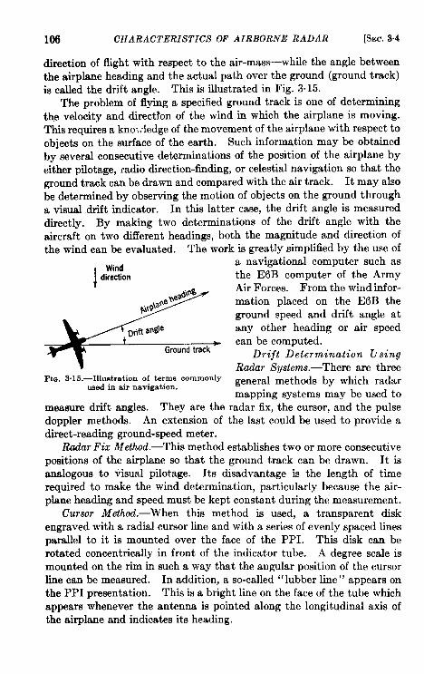
106 CHARACTERISTICS OF AIRBORNE RADAR [SEC.3.4
direction of flight with respect to the air-mass—while the angle betweenthe airplrme heading and the actual path over the ground (ground track)i6 called the drift angle. This is illustrated in Fig. 3.15.
The problem of flying a specified ground track is one of determiningthe velocity and direction of the wind in which the airplane is moving.This requires a kno’:.-ledge of the movement of the airplane with respect toobjects on the surface of the earth. Such information may be obtainedby several consecutive determinations of the position of the airplane byeither pilotage, radio direction-finding, or celestial navigation so that theground track can be drawn and compared with the air track. It may alsobe determined by observing the motion of objects on the ground througha visual drift indicator. In this latter case, the drift angle is measureddirectly. By making two determinations of the drift angle with theaircraft on two different headings, both the magnitude and direction ofthe wind can be evaluated. The work is greatly simplified by the use of
IWhd
direction
FIG. 3.16.—Illustration of terms commonlyused in air navigation.
a navigational computer such asthe E6B computer of the ArmyAir Forces. From the wind infor-mation placed on the E6B theground speed and drift angle atany other heading or air speedcan be computed.
Drijt Determination tisingRadar Systems.—There are threegeneral methods by which radarmapping systems may be used to
measure drift angles. They are the rada~ ‘fix~the cursor, and the pulsedoppler methods. An extension of the last could be used to provide adirect-reading ground-speed meter.
Radar Fix Method.—This method establishes two or more consecutivepositions of the airplane so that the ground track can be drawn. It isanalogous to visual pilotage. Its disadvantage is the length of timerequired to make the wind determination, particularly because the air-plane heading and speed must be kept constant during the measurement.
Cursor Method.—When this method is used, a transparent diskengraved with a radial cursor line and with a series of evenly spaced linesparallel to it is mounted over the face of the PPI. This disk can berotated concentrically in front of the indicator tube. A degree scale ismounted on the rim in such a way that the angular position of the cursorline can be measured. In addition, a so-called “lubber line” appears onthe PPI presentation. This is a bright line on the face of the tube which
appears whenever the antenna is pointed along the longitudinal axis ofthe airplane and indicates its heading.
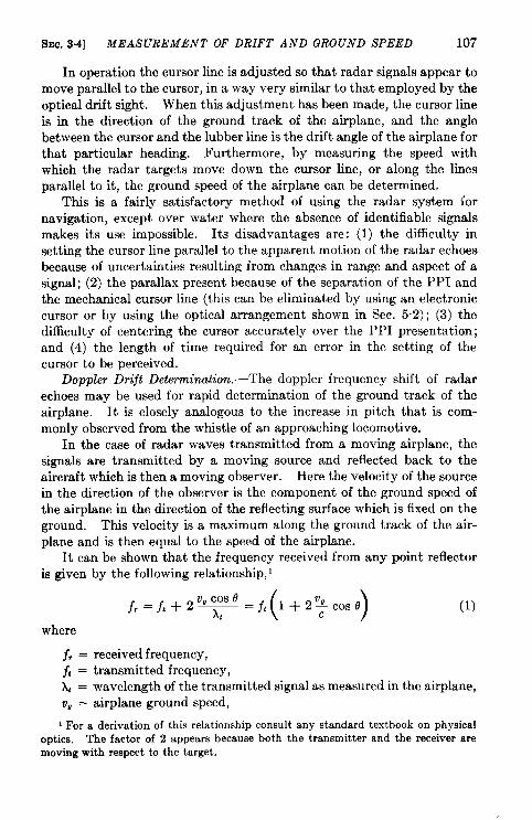
SEC, 3.4] MEASUREMENT OF DRIFT AND GROUND SPEED 107
In operation the cursor line is adjusted so that radar signals appear tomove parallel to the cursor, in a way very similar to that employed by theoptical drift sight. When this adjustment has been made, the cursor lineis in the direction of the ground track of the airplane, and the anglebetween the cursor and the lubber line is the drift angle of the airplane forthat particular heading. Furthermore, by measuring the speed withwhich the radar targets move down the cursor line, or along the linesparallel to it, the ground speed of the airplane can be determined.
This is a fairly satisfactory method of using the radar system fornavigation, except over water where the absence of identifiable signalsmakes its use impossible. Its disadvantages are: (1) the difficulty insetting the cursor line parallel to the apparent motion of the radar echoesbecause of uncertainties resulting from changes in range and aspect of asignal; (2) the parallax present because of the separation of the PPI andthe mechanical cursor line (this can be eliminated by using an electroniccursor or by using the optical arrangement shown in Sec. 5.2); (3) thedifficulty of centering the cursor accurately over the PPI presentation;and (4) the length of time required for an error in the setting of thecursor to be perceived.
Doppler Drift Determination.-The doppler frequency shift of radarechoes may be used for rapid determination of the ground track of theairplane. It is closely analogous to the increase in pitch that is com-monly observed from the whistle of an approaching locomotive.
In the case of radar waves transmitted from a moving airplane, thesignals are transmitted by a moving source and reflected back to theaircraft which is then a moving observer. Here the velocity of the sourcein the direction of the observer is the component of the ground speed ofthe airplane in the direction of the reflecting surface which is fixed on theground. This velocity is a maximum along the ground track of the air-plane and is then equal to the speed of the airplane.
It can be shown that the frequency received from any point reflectoris given by the following relationship, 1
(1)
where
j, = received frequency,j, = transmitted frequency,k~ = wavelength of the transmitted signal as measured in the airplane,V@= airplane ground speed,
1For a derivation of this relationship consult any standard textbook on physicaloptics. The factor of 2 appears because both the transmitter and the receiver aremoving with respect to the target.
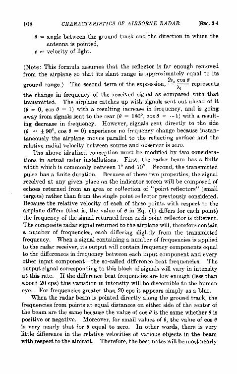
108 CHARACTERISTICS OF AIRBORNE RADAR [SEC.34
0 = angle between the ground track and the direction in which theantenna is pointed,
c = velocity of light.
(Note: This formula assumes that the reflector is far enough removedfrom the airplane so that its slant range is approximately equal to its
2V@cos eground range.) The second term of the expression, ~ represents
the change in frequency of the received signal as compared with thattransmitted. The airplane catches up with signals sent out ahead of it(O = O, cos O = 1) with a resulting increase in frequency, and is goingaway from signals sent to the rear (8 = 180”, cos @ = – 1) with a result-ing decrease in frequency. However, signals sent directly to the side(O = + 90°, cos @ = O) experience no frequency change because instan-taneously the airplane moves parallel to the reflecting surface and therelative radial velocity between source and observer is zero.
The above idealized conception must be modified by two considera-tions in actual radar installations. First, the radar beam has a finitewidth which is commonly between 1° and 106. Second, the transmittedpulse has a finite duration. Because of these two properties, the signalreceived at any given place on the indicator screen will be composed ofechoes returned from an area or collection of “point reflectors” (smalltargets) rather than from the single point reflector previously considered.Because the relative velocity of each of these points with respect to theairplane differs (that is, the value of 0 in Eq. (1) cliffers for each point)the frequency of the signal returned from each point reflector is different.The composite radar signal returned to the airplane will, therefore containa number of frequencies, each differing slightly from the transmittedfrequency. When a signal containing a number of frequencies is appliedto the radar receiver, its output will contain frequency components equalto the differences in frequency between each input component and everyother input component—the so-called difference beat frequencies. Theoutput signal corresponding to this block of signals will vary in intensityat this rate. If the difference beat frequencies are low enough (less thanabout 20 cps) this variation in intensity will be discernible to the humaneye. For frequencies greater than 20 cps it appems simply as a blur.
When the radar beam is pointed directly along the ground track, thefrequencies from points at equal distances on either side of the center ofthe beam are the same because the value of cos o is the same whether o ispositive or negative. Moreover, for small values of O,the value of cos ois very nearly that for 8 equal to zero. In other words, there is verylittle difference in the relative velocities of various objects in the beamwith respect to the aircraft. Therefore, the beat notes will be most nearly
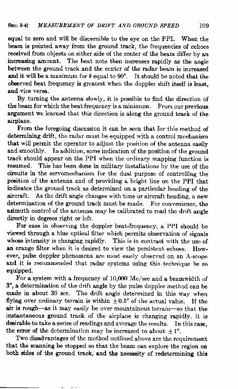
SEC. 3°4] MEASUREMENT OF DRIFT AND GROUND SPEED 109
equal to zero and will be discernible to the eye on the PPI. When thebeam is pointed away from the ground track, the frequencies of echoesreceived from objects on either side of the center of the beam differ by anincreasing amount. The beat note then increases rapidly as the anglebetween the ground track and the center of the radar beam is increasedand it will be a maximum for o equal to 90°. It should be noted that theobserved beat frequency is greatest when the doppler shift itself is least,and vice versa.
By turning the antenna slowly, it is possible to find the direction ofthe beam for which the beat frequency is a minimum. From our previousargument we learned that this direction is along the ground track of theairplane.
From the foregoing discussion it can be seen that for this method ofdetermining drift, the radar must be equipped with a control mechanismthat will permit the operator to adjust the position of the antenna easilyand smoothly. In addition, some indication of the position of the groundtrack should appear on the PPI when the ordinary mapping function isresumed. This has been done in military installations by the use of thecircuits in the servomechanism for the dual purpose of controlling theposition of the antenna and of providing a bright line on the PPI thatindicates the ground track as determined on a particular heading of theaircraft. As the drift angle changes with time or aircraft heading, a newdetermination of the ground track must be made. For convenience, theazimuth control of the antenna may be calibrated to read the drift angledirectly in degrees right or left.
For ease in observing the doppler beat-frequency, a PPI should beviewed through a blue optical filter which permits observation of signalswhose intensity is changing rapidly. This is in contrast with the use ofan orange filter when it is desired to view the persistent echoes. How-ever, pulse doppler phenomena are most easily observed on an A-scopeand it is recommended that radar systems using this technique be soequipped.
For a system with a frequency of 10,OOOMe/see and a beamwidth of3°, a determination of the drift angle by the pulse doppler method can bemade in about 30 sec. The drift angle determined in this way whenflying over ordinary terrain is within Y 0.5° of the actual value. If theair is rough—as it may easily be over mountainous terrain—so that theinstantaneous ground track of the airplane is changing rapidly, it isdesirable to take a series of readings and average the results. In this case,the error of the determination may be increased to about + 1°.
Two disadvantages of the method outlined above are the requirementthat the scanning be stopped so that the beam can explore the region onboth sides of the ground track, and the necessity of redetermining thie
110 CHARACTERISTICS OF AIRBORNE RADAR [SEC. 3.5
track wherever a major change in the airplane heading is made. Anideal system would have an instantaneous direct indication of the groundtrack of the airplane at all times. The fact that several unsuccessfulattempts to perform this function have been made emphasizes both itsdifficulty and desirability.
Possibility of Instantaneous Ground-speed Determination by DopplerMethod.—An examination of Eq. (1) discloses the interesting fact that theabsolute value of the doppler frequency shift of radar waves when meas-ured along the ground track is directly proportional to the ground speed ofthe aircraft. Therefore, a direct-reading frequency meter could serve asa ground-speed indicator. Along the ground track (0 = O), the doppler
frequency shift becomes exactly ~ v,. Specifically, the doppler shift for
a ground speed of 150 mph and a frequency of 11,780 Me/see (a wave-length of 2.54 cm) would be 5280 cps, whereas at 300 mph it would betwice this value. These frequencies are in the audible range wheredirect-reading frequency meters have been available for some time.
Several methods of using this phenomenon to measure the groundspeed of airplanes have been proposed. As in the case of radio altimeters,either continuous wave or pulsed radiation may be used; the argumentswhich have been brought forward do not conclusively favor either.Sufficient power must be available in order that echoes will be receivedfrom targets at ranges so great that the slant range and ground range arenearly equal, or as an alternative the antennas might be arranged topoint down at a fixed known angle.
The antenna system employed might be either a rotatable beam ortwo fixed antennas with one pointed to the right and the other pointed tothe left of the longitudinal axis of the airplane. In the former, it will benecessary to point the antenna in the direction in which the ground speedis a maximum to determine the ground track and speed. In the latter,a vector addition of the two components of ground speed obtained fromthe two antennas will determine both ground speed and track.
Although no completely successful system employing the dopplerfrequency shift to measure the ground speed of aircraft has yet beenbuilt, future development may unravel the difficulties and provide theairplane with the equivalent of the automobile speedometer.
3.6. Determination of Drift and “Ground Speed” Over Water.1—Theoptical solution to the problem of drift and “ground speed” over watermay be simple when weather does not interfere with visual sighting ofthe water surface. In daylight the optical-drift sight may be used tosight on wave crests or on a drift marker—an object dropped from theaircraft in flight which floats on the surface of the water. At night,
1By J. J. Hibbert and N. W. MacLean.
SEC. 3.5] DRIFT AND “GROUND SPEED” OVER WATER 111
floating flares may be dropped. Information obtained in these ways isused in the manner described in the preceding section. Overwater sightsgive the relative air-ocean current drift, but because the ocean current issmall, the measurement is usually regarded as one of drift relative to theground.
Just as in overland navigation, drift angle may be found from twofixes obtained in any convenient way. Unfortunately, in overwaternavigation, when the only signal available is the echo from the sea itself,the pulse doppler radar technique has not yet been applied successfully.Limited tests indicate that a radar system with a frequency of 10,000Me/see (3 cm) and a beamwidth of 3° gives no indication of the ground,track when flying over water. on the other hand, at 3000 Me/see L
(10 cm) with a 7° beam, a minimum beat frequency can be detected but,no change in it can be observed over an angle of 20° centered about theground track.
Although the reason for th~ apparent failure of the conventional pulsedoppler technique has not been established definitely, it is probably theresult of extraneous doppler frequency shifts caused by the motion o~ thewaves or ripples. Each of the reflecting wave or ripple surfaces is movmgwith its own particular velocity which must be considered in calculatingthe doppler shift of the radar signal. Because this velocity may. varyfrom wave to wave and over the surface of a single wave, the echo signalwill contain a mixture of frequencies. Even if the radar beam, werepointed directly along the ground track of the airplane and there were aminimum frequency corresponding to the aircraft motion, this frequencymight be masked by the doppler frequencies caused by the movementof the waves.
This hypothesis would also explain the failure to detect any freqkenc$ -minimum when 10,000 Me/see are used, while a rough minimum can bedetected at frequencies in the vicinity of 3000 Me/see. At the higherfrequency, minor irregularities moving with random velocities on thewave surface are large enough to reflect a substantial amount of energy.Therefore, a much greater random variation in the degree of frequencyshift would be expected. At 3000 Me/see, the signal is returned mainlyfrom the larger waves and hence is not subject to so many perturbations.
In spite of this somewhat discouraging prospect, experimental evi-dence is far from complete, and so it is entirely possible that for someother radar frequency and beamwidth a puke doppler determination ofground track over water could be developed. Moreover, modified appli-cations of the doppler phenomena such as those described in Sec. 3.4might provide both ground-speed and drift information.
The approximate direction of surface winds may sometimes beobtained by noting the appearance of sea return on the radar screen.
112 CHARACTERISTICS OF AIRBORNE RADAR [SEC,36
If the surface wind direction has been fairly constant fora period of afew hours, seareturn will be most prominent inadirection upwind fromthe aircraft.
Corner reflectors that can be dropped from the airplane (see Sec. 9.4)have been used over water to provide radar signals useful in determiningdrift and ground speed. The maximum range at which such reflectorshave been ofvalue tothisproblem at3cmis about 6 miles. This meansthat by suitable maneuvering of the aircraft, the reflector could beobserved during about 12 miles of flight. The maximum range at whichcorner reflectors can be used decreases as the altitude of the aircraftincreases because of the nature of the reflector radiation pattern. Thehighest altitude at which nominal ranges of 5 or 6 miles can be obtainedusing the corner reflectors now available is about 5000 ft. The maximumrange is reduced by rough seas.
Fixed radar beacons (Sec. 1.9) and Gee and Loran (Sees. 2.9 and 2. 10)can be used for drift and ground-speed measurement by taking two fixessome distance apart and making the usual calculations. This method ispreferable because it provides absolute fix data in addition to drift andground speed. Except in the case of Loran, however, it is limited by theshort range of the fixed stations.
3.6. Information Available on Flights over Water. I—In overwaterflight, the value of radar equipment may be seriously limited by theshortage of targets.
Landjall.-It is evident from the discussion on landwater boundariesin Sec. 3“1 that landfall can be easily determined by radar. This informa-tion is extremely valuable for air navigation near a coast line or overregions containing islands.
Surface Vessel Detection.—The radar returns from ships are usuallyvery strong and stand out vividly as spots or short arcs on a PPI againstthe dark background of water areas. In Fig. 3. 16b, several ships maybeseen along the Massachusetts coast south of Boston. They are en routebetween Boston and the Cape Cod Canal. Additional ships may beseen in Buzzard Bay, south of the canal.
Even very small vessels, such as life boats, can be detected at rangesup to 10 miles or more. This fact is of great value in sea-rescue work.Collapsible corner reflectors have been added to the equipment suppliedwith the life rafts carried by ships and airplanes. These reflectors con-siderably increase the radar detection range.
The Problem of Sea Return and Its Alleviation.-In the discussion ofland-water boundaries in Sec. 3.1 it was stated that water areas tend toreflect the radar energy away from the radar antenna. This statementia strictly true only for a perfectly smooth water surface with no waves or
I By D. L. Haglerand G. A. Garrett.
SMC. 3.6] INFORMATION AVAILABLE OVER WATER 113
spray. Such a surface would act as a mirror and would scatter only anegligible amount of energy. This condition rarely, if ever, exists innature; some radar return, therefore, is to be expected from any largebody of water.
This sea return appears as a bright area at the center of the PPIdisplay. It tends to obscure desired signals and may even obliteratethem, as shown in Fig. 3.16a, and thus it may be a limiting factor in theusefulness of a radar equipment.1
Although the exact phenomena which cause the scattering of radarenergy by a rough water surface are not completely understood, theprincipal factors involved have been evaluated. In general, the intensityis greater for heavy winds than for light winds and is greatest from thewindward direction because the size and shape of the waves and theamount of spray near the surface of the water depend upon the intensityand direction of the wind. The maximum range at which saturated seareturn is obtained may be twice as great upwind as downwind. Theintensity increases with increasing angles of incidence from the hori-zontal. The intensity and maximum range at which it appears increaseas the power output, antenna gain, and receiver gain are increased.Measurements made on a 3-cm set show that the maximum range ofsaturated sea return increases rapidly with altitude for the first one ortwo thousand feet, and then at a diminishing rate because of the variationin the angle of incidence. 2
The available information on the effect of polarization on the intensityof sea clutter at 3 cm and 10 cm is given in Table 3“1. It is not veryconclusive.
TAZLE 3.1.—POLARIZATIONGIVINGLEASTSEA RETUFtNFOR GRAZING INCIDENCEAngle between beam and the surface of the sea less than 5°.
r ;P1
Range and azimuth resolution are also important factors. They areparticularly significant when it is necessary to detect the presence of smallcraft within the clutter. The sea return at any one point on the indicatorscreen comes from an area on the surface of the earth of width equal to theradar beamwidth and of length corresponding to the distance light travelsin half the duration of the pulse. The area of the water surface is usually
1E. W. Cowan, “Sea-return Effecteand Their Eliminationin the AN/APS-6,”RL Report No. 707, June 11, 1945.
: Cowan,op. m“t.
I
I
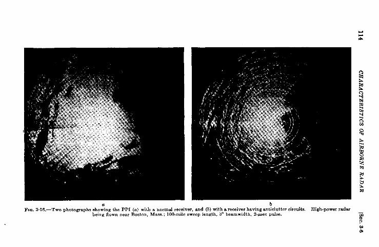
114C
HA
RA
CT
ER
ISTIC
SO
FA
IRB
OR
NE
RA
DA
R
SEC. 3.7] USE OF MAPS AS AIDS TO RADAR PILOTAGE 115
large compared with this area of resolution and therefore intercepts thesame total amount of radar energy regardless of its size. A small shipor a similar object, however, occupies an area which is small comparedto this area of resolution. Thus, if the resolution of the radar @ iaimproved, the ship will intercept a larger fraction of the total radar pulseenergy and will therefore produce a stronger radar return without acorresponding increase in sea return. This increase in the ratio of desiredship return to sea return continues, however, only so long as the radarbeam is wider than the ship or so long as the effective pulse length isgreater than twice the width of the ship. Also, this discussion is baaedon the assumption that changes inlxxmnwidtha ndpulsel engtha remadewithout changing the total transmitted energy per pulse.
Several circuits have been found useful in minimizing the effect of seareturn and are discussed in Microwaw Receitiers, Vol. 23, Chap. 10.Ail circuits accomplish their purpose by lowering the amplitude of thesea-return signal within thereceiver to a value below the saturation limitso that other signals superimposed upon the sea return appear on theindicator. No one circuit is entirely satisfactory as a remedy for seareturn, but certain combinations give great improvement. They arealso useful in alleviating other types of clutter.
A striking pair of PPI photographs showing what can be accomplishedby the use of anticlutter circuits is shown in Fig. 316. It is evident thatmany more ships (or possibly aircraft) can be seen and that Cape Cod ismore clearly delineated when the anticlutter circuits are used.
Airplane Detection over Water.—The radar returns from other aircraftare detected more easily against the return from the ocean than againstthe stronger returns from land objects. The sea-return problems dis-cussed in the above section apply to airplane detection as well as to thedetection of objects on the ocean surface. This subject is discussedfurther in Sec. 4.2.
3.7. The Use of Maps as Aids to Radar Pilotage. ‘—Radar navigationhas been accomplished with the aid of only the conventional navigationalmaps. However, Air Force experience in Europe definitely proved thatthese maps were inadequate for easy navigation for two reasons:
1. They did not give all the information needed by the operator.2. They provided a mass of useless, confusing information.
As a result, special radar-pilotage maps were prepared. The initialmaps on the scale of l-to-1,000,000 included detailed outlines of citiesbased on PPI photographs. In addition, they showed rivers, lakes, andrailroads. These maps proved to be of tremendous help to navigatorsuntil the introduction of higher resolution equipment revealed certain
1By H, Fahnestock, Jr, and J. H. Buck.
116 CHARACTERISTZCSOF AIRBORNE RADAR [SEC. 3.7
undesirable limitations. For example, greater detail was needed in theoutline of built-up areas, and light contour shading seemed neceeawy.In many respects, a l-t&iOO,OOO scale seems best for high-resolutionradar, but this must be balanced, of course, by the amount of territorycovered by any one map.
For any well-traveled route, a great deal of the bulkiness of maps canbe eliminated by the use of strip maps. Preferably these should be sec-tions of special radar maps cut so as to cover territory 25 to 50 miles oneach side of the planned course. As an aid to the operator, pictures ofthe scope appearance at various positions along the course can be joinedto the map at appropriate points. This is unnecessary if the radar mapis well made.
A problem of the Troop Carrier Command, TCC, for example, was tonavigate at night at altitudes below 1000 ft to a predetermined drop zonewhich was most often a small field. As an aid to such navigation, stripphotographs leading from some prominent landmark to the drop zonewere made in daytime from altitudes of 8000 to 10,000 ft. Positivetransparencies were made from these negatives and dyed with a fluores-cent dye. When viewed with an ultraviolet light behind them, thesephotographs were extremely realistic and showed land contours far betterthan most presentations. The films were placed on rollers in a box witha viewing window and an ultraviolet light behind the film. The rollerswere geared to a variable-speed motor synchronized to the ground speedof the aircraft so that the picture in the window corresponded with thepilot’s view of the ground.
A similar technique can be applied to a radar oscilloscope. Periodicphotographs can be taken of a radar oscilloscope during reconnaissancemissions flown with accurate navigation. The photographs can then bemade into a strip and used in a manner similar to the TCC method, withthe viewer set up adjacent to the radar oscilloscope. The navigator orpilot then directs the aircraft so that the picture on his oscilloscopecorresponds to the reconnaissance strip. This has a distinct advantageover the visual photographs in that the maximum range shown by thephotograph can be changed so as to be appropriate to the targets ofgreatest importance to the radar at the part of the trip in question. Insome cases it might be desirable to show one or more beacons with theradar sweep set to 100 miles. The reconnaissance film could then havemarked on it the fact that the radar sweep is to be set to 100 miles forthat section of the film.
Similarly, the sweep could be changed as directed when the airplaneapproaches a coast line, a prominent river, or an airport. If desired,either electrical or optical means can be devised to superpose the recon-~aissance (or, in the case of beacons, probably an artificial reconnais-
SEC. 3.8] RADAR BEACON NA VI(3A TION 117
sance) on top of the picture of the targets being scanned by the radar.The aircraft would then be maneuvered to make the two coincide.
3.8. Radar Beacon Navigation. -A brief description of beacons isgiven in Sec. 1.9.2 Ground beacons automatically transmit continuousinformation concerning their range and bearing to any aircraft inter-rogating them with a suitable radar system. Precise fixes may be deter-mined and courses closely held by using the signals received from beacons.In addition, beacons help solve several special navigational problems.
Taking Fixes. —Because a beacon signal gives both range and bearinginformation, it is sufficient for a fix. The error of this fix is made up ofbearing and range errors. At long ranges, errors in bearing are thegreater because beacon signals usually cannot be read closer than about 1°.An angular inaccuracy of 1° at a range of 200 miles causes an error of 3miles in position. The bearing error will also contain any inaccuracies ofthe compass reading used to convert relative to true bearing; these can besignificantly large at long ranges or in rough air. Range errors are nearlyindependent of the range at which measurements are made and are usuallyless than 500 ft if readings are made on a short sweep.
Another possible source of error in obtaining range fixes is the use ofslant ranges. The size of such errors here maybe reduced by taking fixesonly from beacons at ranges at least several times the altitude or by cor-recting the ranges graphically if they are taken from targets closer thanthis. This error is automatically eliminated, of course, if the radar sweepindicates ground ranges instead of slant ranges.
Because range can be read more accurately than bearing on mostairborne radars, a better fix can be obtained with two beacons than withone. One intersection of the range circles gives the position of the air-craft. The fix error then is made up only of slant-range and readingerrors. Very rough bearing measurements usually resolve the ambiguityarising from the fact that the range circles intersect at two points.
CouTse Indication. -Radar beacons can be used for holding anydesired course within the area covered by a ground installation. If theground stations are set up along an airway, a pilot using a radar scopecan follow the beacon signals and steer directly by reference to the indi-cator screen. Homing is accomplished by keeping the signals from thebeacon centered on the line on the radar scope that represents the courseof the airplane. In the no-wind (or direct-head or tail-wind) conditionthis course line is the same as the heading line; otherwise these two differby the drift angle, for which allowance is made in a radar system exactlyas it is in the conventional radio compass.
I By T. H. Waterman,2 Radar Beacons, Vol. 3, contains detailed discussion of the uses and operation of
beacons.
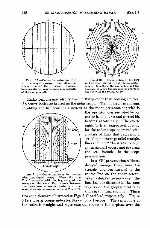
118 CHARACTERISTICS OF AIRBORNE RADAR [SEC.3.8
0
0FIG. 3.17.—Course indicator for PPI FIG. 3.18.—Course indicator for F’PI
with undelayed sweeps. Line O-Ois the with sweeps delayed by half the maximumcourse line of the overlay. Distance range. Line O-Oisthe course line and thebetween theparacourse lines is one-tenth distance between the paracourse curves isof the sweep length one-tenth of the sweep delay.
Radar beacon8 may also be used in flying other than homing courses,
if a course indicator is used on the radar scope. The indicator is a means
of adding another coordinate system to the radar presentation; with itthe operator can see whether or
~Fm. 3.19.—Course indicator for B-scope
with undelayed sweep. When the lineR = O coincides with the beginning of thesweeps on the scope, the distance betweenthe paracourse curves is one-tenth of thesweep distance between R = Oand R = 10D.
not he is on course and correct hisheading accordingly. The courseindicator is a transparent overlayfor the radar scope engraved witha series of lines that represent aset of equidistant parallel straightlines running in the same directionas the aircraft course and coveringthe area included in the scopepresentation.
In a PPI presentation withoutdelayed sweeps these lines arestraight and run parallel to thecourse line on the radar screen.When a delayed sweep is used, thelines become distorted in the sameway as do the geographical rela-tions of the area covered. These
two conditions are illustrated in Figs. 3.17 and 3.18, respectively. Figure3.19 shows a course indicator drawn for a B-scope. The center line ofthe series is straight and represents the course of the airplane over the
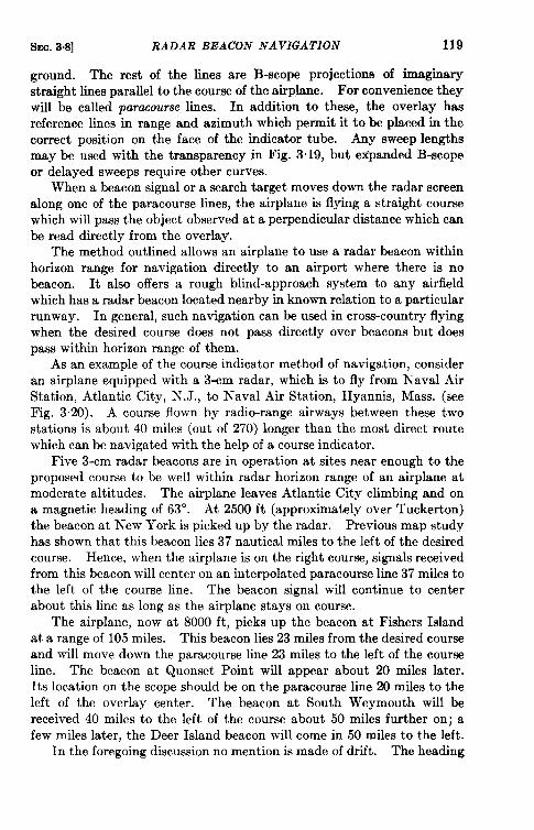
SEC. 3.8] RADAR BEACON NAVIGATION 119
ground. The rest of the limes are B-scope projections of imaginarystraight lines parallel to the course of the airplane. For convenience theywill be called para.course limes. In addition to these, the overlay hasreference lines in range and azimuth which permit it to be placed in thecorrect position on the face of the indicator tube. Any sweep lengthsmay be used with the transparency in Fig. 3.19, but expanded B-scopeor delayed sweeps require other curves.
When a beacon signal or a search target moves down the radar screenalong one of the paracourse lines, the airplane is flying a straight coursewhich will pass the object observed at a perpendicular distance which canbe read directly from the overlay.
The method outlined allows an airplane to use a radar beacon withinhorizon range for navigation directly to an airport where there is nobeacon. It also offers a rough blind-approach system to any airfieldwhich has a radar beacon located nearby in known relation to a particularrunway. In general, such navigation can be used in cross-country flyingwhen the desired course does not pass directly over beacons but doespass within horizon range of them.
As an example of the course indicator method of navigation, consideran airplane equipped with a 3-cm radar, which is to fly from Naval AirStation, Atlantic City, N. J., to Naval Air Station, Hyannis, Mass. (seeFig. 320). A course flown by radio-range airways between these twostations is about 40 miles (out of 270) longer than the most direct routewhich can be navigated with the help of a course indicator.
Five 3-cm radar beacons are in operation at sites near enough to theproposed course to be well within radar horizon range of an airplane atmoderate altitudes. The airplane leaves Atlantic City climbing and ona magnetic heading of 63°. At 2500 ft (approximately over Tuckerton)the beacon at New York is picked up by the radar. Previous map studyhas shown that this beacon lies 37 nautical miles to the left of the desiredcourse. Hence, when the airplane is on the right course, signals receivedfrom this beacon will center on an interpolated paracourse line 37 miles tothe left of the course line. The beacon signal will continue to centerabout this line as long as the airplane stays on course.
The airplane, now at 8000 ft, picks up the beacon at Fishers Islandat a range of 105 miles. This beacon lies 23 miles from the desired courseand will move down the paracourse line 23 miles to the left of the courseline. The beacon at Quonset Point will appear about 20 miles later.Its location on the scope should be on the paracourse line 20 miles to theleft of the overlay center. The beacon at South Weymouth will bereceived 40 miles to the left of the course about 50 miles further on; afew miles later, the Deer Island beacon will come in 50 miles to the left.
In the foregoing discussion no mention is made of drift. The heading
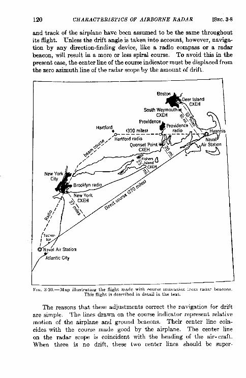
120 CHARACTERISTICS OF AIRBORNE RADAR [SEC.3.8
and track of the airplane have been assumed to be the same throughoutits flight. Unless the drift angle is taken into account, however, navigwtion by any direction-finding device, like a radio compass or a radarbeacon, will result in a more or less spiral course. To avoid this in thermesent case, the center line of the course indicator must be displaced from~he zero azimuth line of the radar scope by the amount of drift.
Boston
&T
Deer Island. CXEH
+*“’h&:fOfi’h-$$q
Providence ~\~4
Hartfordt(310 miles) t“
i
p.. ––––-- ,/ Hartford radio
\%*/..4 / Ouonset Point W-d
//’,’Tucker.1 tonI
fiav21 Air Station
/ AtlanticCity
FIG. 320.-Map illustrating the flight made with course mmcaucm imm radar beacons.This flight is described in detail in the text.
The reasons that these adjustments correct the navigation for driftare simple. The lines drawn on the course indicator represent relativemotion of the airplane and ground beacons. Their center line coin-cides with the course made good by the airplane. The center lineon the radar scope is coincident with the heading of the air-craft.When there is no drift, these two center lines should be super-
SEC.3,8] RADAR BEACON NAVIGATION 121
posed. When there is drift, the two center lines should be displaced sothat the course line of the overlay is superposed on the azimuth line ofthe video which corresponds with the track of the airplane.
Fortunately the slant-range error is negligible for general navigationexcept at short ground ranges and high altitudes. At 10,000 ft or less,course errors resulting from slant-range effect will be less than 1 mile evenwhen the airplane is almost over the beacon. For practical purposes,this factor may be safely neglected at low and medium altitudes. Athigh and very high altitudes only signals 25 miles or more in range shouldbe used for course indication unless the distance of the beacon from thecourse is 10 miles or more.
Radar beacons could be used with course indicators in this way to setup parallel air traffic lanes. These would add a horizontal dimension tothe present vertical stratification of air traffic. Such an application wouldpermit the use of several air lanes on either side of a course marked bybeacons.
Special Applica~ion.s.-There are several special applications for whichground beacons might be used. For example, they could be used as aidsin blind approach to airport runways. Several lightweight portablebeacons already developed are suitable for this purpose. They could bemounted on trucks with their own power supply and moved from onerunway to another as the need arose. Separate beacons could markthe ends of the strip, and additional equipment could be so located as toindicate critical turns in the let-down procedure. In an emergency,trucks with such beacons could be used to set up temporary navigationalaids at auxiliary landing fields where no permanent setup exists. Thisapplication is discussed at greater length in Sec. 1.9.
Radar beacons in permanent installations might be valuable asanticollision markers for high obstructions near the airways, like partic-ularly dangerous skyscrapers and mountains. A special type of obstruc-tion marker would be an airborne beacon informing the pilot of thewhereabouts of any other nearby aircraft. Airborne radar beacons haveother uses and are discussed in more detail in Sec. 7.10.
Radar beacons can also be shipborne. Possible applications of thissort would include homing indication for aircraft employed in ship-to-shore mail transfer or other special services. Lightships may also proveto be useful beacon sites to aid aircraft navigating over continentalshelf waters.
CHAPTER 4
SPECIAL AIDS AND DEVICES
BY W. J. TULL, R. H. MtiLLER, R. M. ROBERTSON,AND R. L. SINSHEI~ER
NAVIGATION AND ANTICOLLISION
4.1. The Ground Position Indicator. ‘A ground position indicator,GPI, is a device that continuously shows the position of the vehicle thatcarries it. The position is usually indicated either by latitude andlongitude or by E-W and N-S distances from a point of departure.Information on the speed and direction of the vehicle is fed into the GPIcontinuously. It resolves the speed into components of velocity, multi-plies the component velocities by the elapsed time to get the correspond-ing displacements, and adds these partial displacements to get the totaldisplacements. These are automatically added to the coordinates of thestarting point to give the display of the coordinates of position at anyinstant.
A GPI can be used only when means are provided for determining aninitial fix and instantaneous values of ground speed and direction. Thecombination of a radar set, a true-airspeed meter, and a compass canprovide all the necessary data for purposes of navigation. The GPIdescribed in this section is one designed to be used in aircraft equippedwith those three instruments. A GPI for some other vehicle might differin minor detail but would be much the same in principle.
The GPI is made so that it will yield the following information:
1. The total distance traveled (given as two components of displace-ment).
2. The position of the aircraft relative to any landmark that gives aradar signal, obtained by setting an electronic index or crosshairscoincident with the radar signal.
3. The heading to be steered in order to follow a direct course to somedesired destination.
4. The time that will be required to reach that destination if theprescribed course is flown.
An airborne GPI must be more complicated than one that would beused on a ship for two reasons: (1) the radar set measures slant range to
1By W. J. Tull, R. H. Miiller.122
SEC. 4.1] THE GROUND POSITION INDICATOR 123
the radar target; this must be corrected for altitude to get the correspond-ing distance from the point on the earth directly below the airplane tothe target; (2) from the true-airspeed meter and compass, the componentsof the velocity in the air mass are readily computed but they differ fromthe components of the ground velocity by the amounts of the correspond-ing components of the velocity of the wind. Ocean currents producesimilar but much smaller effects. The airborne GPI, then, must be soarranged that the components of the wind velocity can be determinedand set in as a continuously operating correction.
The individual measurements which are to be set into the computerare described below.
Fix Determination.-The position of the aircraft is established bymeasurements of three quantities. They are the difference in altitudebetween the aircraft and the landmark, the slant-range or straight-linedistance between the aircraft and the landmark, and the direction of thelandmark relative to the aircraft.
The altitude H is set into the computer by making a range markcoincide with the first (nearest) radar signal appearing on the scope.This signal is assumed to come from a target almost directly under theaircraft. The altitude knob with which the range setting is made intro-duces the information into the computer.
The components of the fix mileage are adjusted until the crosshairscoincide with the reference signal on the PPI.
When these operations have been performed, it is possible to readfrom dials the altitude of the aircraft above the ground and its groundposition with respect to the reference point. Ground position is repre-sented in rectangular coordinates by two fix dials, one corresponding toX miles in the east-west, the other 1’ miles in the north-south, direction.The compass bearing of the landmark has been taken account of auto-matically by the GPI, into which the readings of the compass are con-tinually fed. From this point on, all GPI computations are made in aplane parallel to the surface of the earth, the H factor being used only toconvert slant-range radar data to GPI ground-range information.
Rate Determh.tion.-The ground rate of the vehicle is determined byvector addition of the true airspeed and the wind speed. The GPI ismade so that thk vector addition can be made easily.
Suppose that the crosshaks have been set on a reference signal butthat no correction for the wind has been put in. The crosshairs will thendrift away from the reference si~al with the direction and speed of thewind because the crosshairs are continuously shifted by the GPI ody inaccord with the velocity with respect to the air. If, however, the cor-rection for the wind has been set in properly the crosahairs will remainhi coincidence with the reference.
124 SPECIAL AIDS AND DEVICES [SEC. 4.1
Wind correction M put into the computer by a simple process knownas “memory point tracking.” The operator sets the electronic indexcoincident with the landmark on the radar range scope, pushes a switch,waits until the index has drifted away from the reference by an appre-ciable amount, and then resets it on the landmark. The GPI thenautomatically computes and sets in the correct components of windvelocity that would have caused the marker to remain coincident with theradar signal. The computer has automatically taken two fixes, comparedthe components of true displacement and apparent displacement, meas-ured the elapsed time, computed the components of the wind velocity,and set in the resulting values as a continuing correction.
Course De&rmination.-The course of the vehicle is set by placing theelectronic index on the point over which it is desired to fly. This can bedone in two ways. The first method consists simply of placing theindex in coincidence with a signal, by a means involving the direct com-parison of the relative position of the two as they appear on the radarscope. The second method performs the same function for points thatdo not appear on the radar scope. This method takes advantage of theknowledge of present position obtained from the GPI and the operator’sability to set the fix dials at desired future position numbers. Becausethe fix dials define the position of the crosshairs, they will appear in thecorrect position on the radar scope whether a radar signal is there or not,provided that the correct future position has been set on the dials.
With the crosshairs set on this point over which it is desired to fly,the computer will indicate both the change in headiig and the time to go,which is necessary in order to reach the point in question.
Navigational Procedure.-The practice of GPI navigation has beenmade simple and permits accurate navigation with great facility. Thisprocedure is outlined in four steps as follows:
1. Determine radar altitude.2. Measure wind.3. Set present-position dials to indicate position of aircraft.4. Proceed with check-point navigation.
Steps 1 and 2 have been described. The fix dials indicate in north-south and east-west components the ground range and direction to anyreference on which the crosshairs are set.
In Fig. 4.1 the fix dials (outer dials) show that the crosshairs are seton a point which is 18 miles north and 11 miles east of the aircraft. Ifthe aircraft should proceed to this point the zeros of the fix dials will thenhave moved under the cursor, and on the PPI the crosshahs will havemoved into the center of the oscilloscope. Clearly, the zeros of the fl.xdials may be thought of as representing the crosshairs. Now suppoee
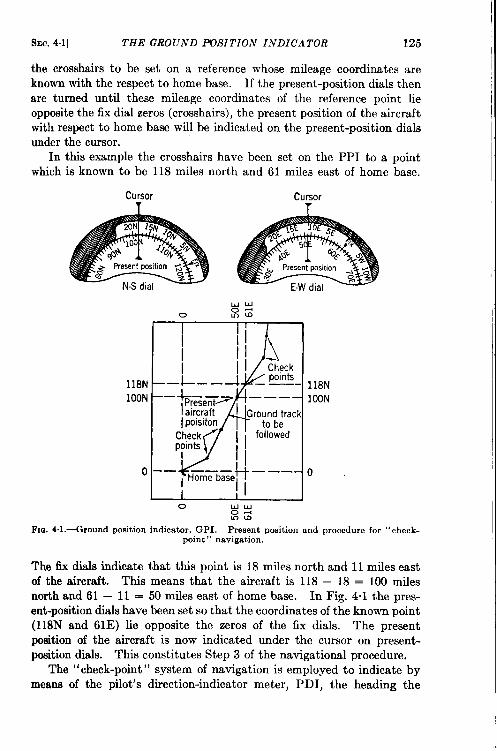
SEC. 4.1] THE GROUND POSITION INDICATOR 125
the crosshairs to be set on a reference whose mileage coordinates areknown with the respect to home base. If the present-position dials thenare turned until these mileage coordinates of the reference point lieopposite the fix dial zeros (crosshairs), the present position of the aircraftwith respect to home base will be indicated on the present-position dialsunder the cursor.
In this example the crosshairs have been set on the PPI to a pointwhich is known to be 118 miles north and 61 miles east of home base.
Cursor Cursor
III
118N— –l.-lOON—
ipoisiton
Checkp;ints
oI
Fm 4.1 .+round
0 Uu0-!mu)
position indicator, GPI, Present position and procedurepoint” navigation.
for “
The fix dials indicate that this point is 18 miles north and 11 miles eastof the aircraft. This means that the aircraft is 118 – 18 = 100 milesnorth and 61 — 11 = 50 miles east of home base. In Fig. 4.1 the pres-ent-position dials have been set so that the coordinates of the known point(118N and 61E) lie opposite the zeros of the fix dials. The presentposition of the aircraft is now indicated under the cursor on present-position dials. This constitutes Step 3 of the navigational procedure,
The “check-point” system of navigation is employed to indicate bymeans of the pilot’s direction-indicator meter, PDI, the heading the
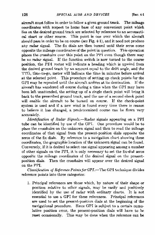
126 &’PECIAL AIDS AND DEVICES [SEC, 4.1
aircraft must follow in order to follow a given ground track. The mileagecoordinates with respect to home base of any convenient point whichlies on the desired ground track are selected by reference to an aeronauti-cal chart or other source. This point is one over which the aircraftshould pass in order to be on course (see Fig. 4“1), and it need not produceany radar signal. The fix dials are then turned until their zeros comeopposite the mileage coordinates of the point in question. This operationplaces the crosshairs over this point on the PPI even though there maybe no radar signal. If the function switch is now turned to the courseposition, the PDI meter will indicate a heading which is upwind fromthe desired ground track by an amount equal to the drift angle, and theTTG, time-to-go, meter will indicate the time in minutes before arrivalat the selected point. This procedure of setting up check points for theGPI may be repeated until the aircraft arrives at its destination. If theaircraft has wandered off course during a time when the GPI may havebeen left unattended, the setting up of a single check point will bring itback to the prescribed ground track, and the use of a second check pointwill enable the aircraft to be turned on course. If the check-pointsystem is used and if a new wind is found every time there is reasonto believe it has changed, a predetermined course can be flown veryaccurately.
Identification of Radar Signals.—Radar signals appearing on a PPItube can be identified by use of the GPI. One procedure would be toplace the crosshairs on the unknown signal and then to read the mileagecoordinates of that signal from the present-position dials opposite thezeros of the fix dials. By reference to a navigation chart showing thesecoordinates, the geographic location of the unknown signal can be found.Conversely, if it is desired to select one signal appearing among a numberof other signals on the PPI, it is only necessary to set the fix-chal zerosopposite the mileage coordinates of the desired signal on the present-position dials. Then the crosshairs will appear over the desired signalon the PPI.
Cla-ssijkation of Reference Points for GPI.—The GPI technique dividesreference points into three categories:
1. Principal references are those which, by nature of their shape orposition relative to other signals, may be easily and positivelyidentified by the use of radar with ordinary charts. It is notessential to use a GPI for these references. Principal referencesare used to set the present-position dials at the beginning of thenavigational procedure. Since GPI is subject to a certain cumu-lative position error, the present-position dials will have to bereset occasionally. This may be done when the reference can be
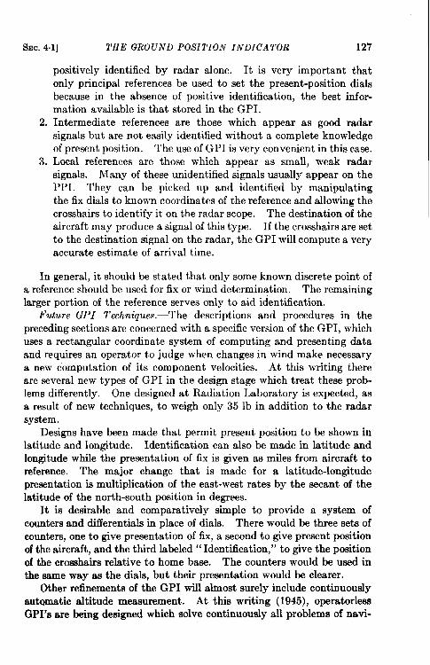
SEC. 4.1] THE GROUND POSITION INDICATOR 127
positively identified by radar alone. It is very important thatonly principal references be used to set the present-position dialsbecause in the absence of positive identification, the best infor-mation available is that stored in the GPI.
2. Intermediate references are those which appear as good radarsignals but are not easily identified without a complete knowledgeof present position. The use of GPI is very convenient in this case.
3. Local references are those which appear as small, weak radarsignals. Many of these unidentified signals usually appear on thePPI. They can be picked up and identified by manipulatingthe fix dials to known coordinates of the reference and allowing thecrosshairs to identify it on the radar scope. The destination of theaircraft may produce a signal of this type. If the crosshairs are setto the destination signal on the radar, the GPI will compute a veryaccurate estimate of arrival time.
In general, it should be stated that only some known discrete point ofa reference should be used for fix or wind determinantion. The remaininglarger portion of the reference serves only to aid identification.
Future GPI Techniques.—The descriptions and procedures in thepreceding sections are concerned with a specific version of the GPI, whichuses a rectangular coordinate system of computing and presenting dataand requires an operator to judge when changes in wind make necessarya new computation of its component velocities. At this writing thereare several new types of GPI in the design stage which treat these prob-lems differently. One designed at Radiation Laboratory is expected, asa result of new techniques, to weigh only 35 lb in addition to the radarsystem.
Designs have been made that permit present position to be shown inlatitude and longitude. Identification can also be made in latitude andlongitude while the presentation of fix is given as miles from aircraft toreference. The major change that is made for a latitude-longitudepresentation is multiplication of the east-west rates by the secant of thelatitude of the north-south position in degrees.
It is desirable and comparatively simple to provide a system ofcounters and differentials in place of dials. There would be three sets ofcounters, one to give presentation of fix, a second to give present positionof the aircraft, and the third labeled “Identification,” to give the positionof the crosshairs relative to home base. The counters would be used inthe same way as the dials, but their presentation would be clearer.
Other refinements of the GPI will alinost surely include continuouslyautomatic altitude measurement. At this writing (1945), operatorlessGPI’s are being designed which solve continuously all problems of navi-
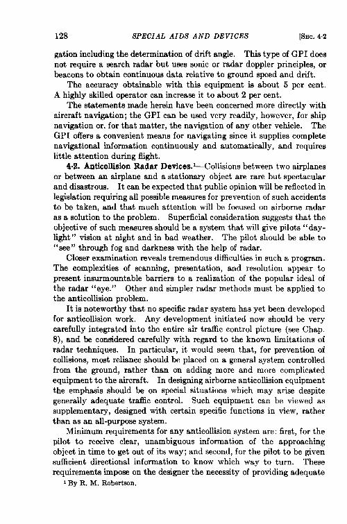
128 SPECIAL AIDS AND DEVICES [t?iEc.4.2
gation including the determination of drift angle. This type of GPI doesnot require a search radar but uses sonic or radar doppler principles, orbeacons to obtain continuous data relative to ground speed and drift.
The accuracy obtainable with this equipment is about 5 per cent.A highly sidled operator can increase it to about 2 per cent.
The statements made herein have been concerned more directly withaircraft navigation; the GPI can be used very readily, however, for shipnavigation or, for that matter, the navigation of any other vehicle. TheGPI offers a convenient means for navigating since it supplies completenavigational information continuously and automatically, and requireslittle attention during flight.
4.2. Anticollision Radar Devices.1-Collisions between two airplanesor between an airplane and a stationary object are rare but spectacularand disastrous. It can be expected that public opinion will be reflected inlegislation requiring all possible measures for prevention of such accidentsto be taken, and that much attention will be focused on airborne radaras a solution to the problem. Superficial consideration suggests that theobjective of such measures should be a system that will give pilots “day-light” vision at night and in bad weather. The pilot should be able to“see” through fog and darkness with the help of radar.
Closer examination reveals tremendous difficulties in such a program.The complexities of scanning, presentation, and resolution appear topresent insurmountable barriers to a realization of the popular ideal ofthe radar “eye.” Other and simpler radar methods must be applied tothe anticollision problem.
It is noteworthy that no specific radar system has yet been developedfor anticollision work. Any development initiated now should be verycarefully integrated into the entire air traffic control picture (see Chap.8), and be considered carefully with regard to the known limitations ofradar techniques. In particular, it would seem that, for prevention ofcollisions, most reliance should be placed on a general system controlledfrom the ground, rather than on adding more and more complicatedequipment to the aircraft. In designing airborne anticollision equipmentthe emphasis should be on special situations which may arise despitegenerally adequate traffic control. Such equipment can be viewed assupplementary, designed with certain specific functions in view, ratherthan as an all-purpose system.
Minimum requirements for any anticollision system are: first, for thepilot to receive clear, unambiguous information of the approachingobject in time to get out of its way; and second, for the pilot to be givensufficient directional information to know which way to turn. Theserequirements impose on the designer the necessity of providing adequate
1By R. M. Robertson.
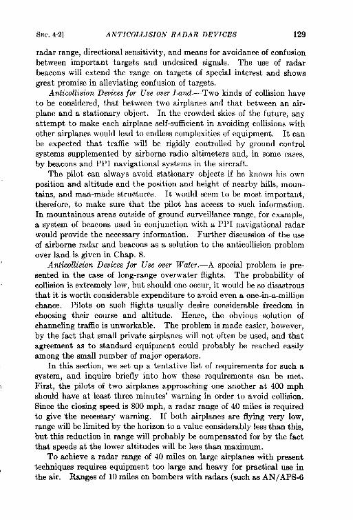
SEC.4.2] ANTICOLLISION RADAR DEVICES 129
radar range, directional sensitivityy, and means for avoidance of confusionbetween important targets and undesired signals. The use of radarbeacons will extend the range on targets of special interest and showsgreat promise in alleviating confusion of targets.
Anticollision Devices jor Use over Land.—Two kinds of collision haveto be considered, that between two airplanes and that between an air-plane and a stationary object. In the crowded skies of the future, anyattempt to make each airplane self-sufficient in avoiding collisions withother airplanes would lead to endless complexities of equipment. It canbe expected that traffic will be rigidly controlled by ground controlsystems supplemented by airborne radio altimeters and, in some cases,by beacons and PPI navigational systems in the aircraft.
The pilot can always avoid stationary objects if he knows his ownposition and altitude and the position and height of nearby hills, moun-tains, and man-made structures. It would seem to be most important,therefore, to make sure that the pilot has access to such information.In mountainous areas outside of ground surveillance range, for example,a system of beacons used in conjunction with a PPI navigational radarw-ould provide the necessary information. Further discussion of the useof airborne radar and beacons as a solution to the anticollision problemover land is given in Chap. 8.
Anticollision Devices for Use over Water.—A special problem is pre-sented in the case of long-range overwater flights. The probability ofcollision is extremely low, but should one occur, it would be so disastrousthat it is worth considerable expenditure to avoid even a one-in-a-millionchance. Pilots on such flights usually desire considerable freedom inchoosing their course and altitude. Hence, the obvious solution ofchanneling traffic is unworkable. The problem is made easier, however,by the fact that small private airplanes will not often be used, and thatagreement as to standard equipment could probably be reached easilyamong the small number of major operators.
In this section, we set up a tentative list of requirements for such asystem, and inquire briefly into how these requirements can be met.First, the pilots of two airplanes approaching one another at 400 mphshould hwe at least three minutes’ warning in order to avoid collision.Since the closing speed is 800 mph, a radar range of 40 miles is requiredto give “the necessary warning. If both airplanes are flying very low,range will be limited by the horizon to a value considerably less than this,but this reduction in range will probably be compensated for by the factthat speeds at the lower altitudes will be less than maximum.
To achieve a radar range of 40 miles on large airplanes with presenttechniques requires equipment too large and heavy for practical use inthe air. Ranges of 10 miles on bombers with radars (such as AN/APS-6
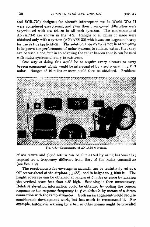
130 SPECIAL AIDS AND DEVICES [SEC.4.2
and SCR-724)) designed for aircraft interception use in World War IIwere considered exceptional, and even then pronounced difficulties wereexperienced with sea return in all such systems. The components ofAN/APS-6 are shown in Fig. 4.2. Ranges of 40 miles or more wereobtained only with a system (AN/APS-20) which was too large and heavyfor use in this application. The solution appears to lie not in attemptingto improve the performance of radar systems to such an extent that theycan be used alone, but in so adapting the radar beacon that it can be usedwith radar systems already in existence. “
One way of doing this would be to require every aircraft to carrybeacon equipment which would be interrogated by a sector-scanning PPIradar. Ranges of 40 miles or more could then be obtained. Problems
Fm. 4.2.—Components of AN /APS-6 system.
of sea return and cloud return can be eliminated by using beacons thatrespond at a frequency different from that of the radar transmitter(see Sec. 1.9).
The requirements for coverage in azimuth can be tentatively set at a90° sector ahead of the airplane ( +450), and in height to + 1000 ft. Theheight coverage can be obtained at ranges of 5 miles or more by makingthe vertical beam less than 4.5° high. Scanning is then unnecessary.Relative elevation information could be obtained by coding the beaconresponse or the response frequency to give altitude by means of a directconnection with the radio altimeter. Such an arrangement would requireconsiderable development work, but has mtich to recommend it. Forexample, automatic warning by a bell or other means might be provided
S- 4.2] ANTICOLLISION RADAR DEVICES 131
when a signal is received that indicates an aircraft approaching at nearlythe same height.
If accurate relative elevation could be obtained from the beaconresponse, the system would be simplfied by having the aircraft changealtitude to avoid an impending collision, instead of turning away from it.A convention might be established by which, for example, only east-bound aircraft would take evasive action by diving or climbing. Such asystem would relax the requirement on azimuth directional informationand might permit use of a simple nonscanning system.
ALTITUDE DETERMINATION
BY R. L. SINSHEIMER
Radio altimeters determine altitude by measurement of the timerequired for radio energy to travel from an airplane to the earth and back.They provide an absolute measure of the clearance of the airplane abovethe terrain. Barometric altimeters, on the other hand, measure the alti-tude of the airplane above sea level. The accuracy of the height indica-tion of a barometric altimeter rests upon two assumptions: fist, that theobserved atmospheric pressure on the ground beneath the airplane hasnot changed since the zero of the altimeter was last adjusted, and second,that the atmospheric pressure decreases at the assumed rate with increas-ing altitude. Because both of these assumptions are affected by meteor-ological fluctuations, the accuracy of barometric altimeter readings isalso similarly affected.
Meteorological conditions, however, do not influence the accuracy ofradio altimeters. Because these devices provide a rough profile of theterrain below the airplane, they can be used to a limited extent for navi-gation. For example, when an airplane crosses a coastline toward land,the altimeter indication will suddenly become slightly unsteady andfluctuate with variations of the terrain.
Methods for navigation over water which take advantage of thedifferent properties of the radio and barometric altimeters have beendevieed. For example, fairly accurate measurements of crosswind canbe obtained by utilizing the radio altimeter as a standard for observingchanges in atmospheric pressure as shown on the barometric altimeter. ~With thiB information it is possible to hold a more accurate course. Thistectilque, however, is limited to overwater flights on which the radioaltitude is the true altitude above sea level.
Two types of radio altimeters, one using the pulse technique, the otherfrequency modulation, are in common use. In the following sections
I AAF Board Report 3265B413.44.
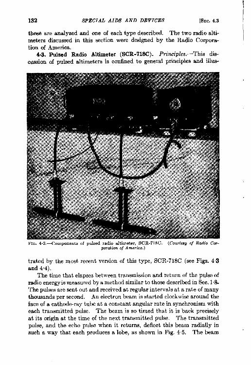
132 SPECIAL AIDS AND DEVICES [Smc. 4.3
these are analyzed and one of each type described. The two radio alti-meters discussed in this section were designed by the Radio Corpora-tion of America.
4.3. Pulsed Radio Altimeter (SCR-718C). Principles.-This dis-cussion of pulsed altimeters is confined to general principles and ilhs-
FIG. 4.3.—Components of pulsed radio altimeter, SCR-718C. (Courtwti Of Radio Cor-poration of America.)
tinted by the most recent version of this type, SCR-718C (see Figs. 4“3and 4.4).
The time that elapses between transmission and return of the pulse ofradio energy is measured by a method similar to those described in Sec. 1“8.The pulses are sent out and received at regular intervals at a rate of manythousands per second. An electron beam is started clockwise around theface of a cathode-ray tube at a constant angular rate in synchronism witheach transmitted pulse. The beam is so timed that it is back preciselyat its origin at the time of the next transmitted pulse. The transmittedpulse, and the echo pulse when it returns, deflect this beam radially insuch a way that each produces a lobe, as shown in Fig. 4“5. The beam
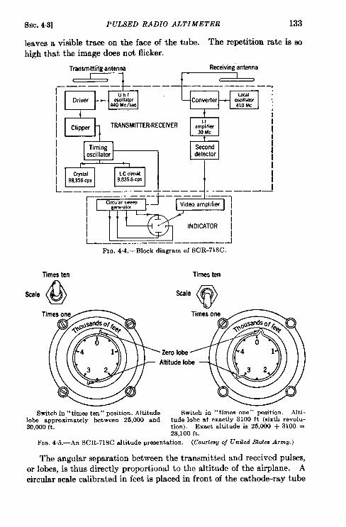
SEC. 4.3] PULSED RADIO ALTIMETER 133
leaves a visible trace on the face of the tube. The repetition rate is sohigh that the image does not flicker.
Trammitt~antenna Receiving-antenna
c——. —.—
4
;:;’I’F
———— ————————.Uhf Local i
Drwer oscillator Converter440Mckc
.awillator410Mc
1.1I Clipper TRANSMlllER.RECEIVER amphfier
30Mc
Timing Second 1
oscillator detector 4
1
I
LCcircuitI 9S!3%’:P 9,835.6CPS iL______________ –––– - .____–—l
[!1— ——Fm. 4.4.—B1ock diagram of SCR-718C.
Times ten Times ten
Scale
// [h l~\ \ \=Ze
Switch in ‘‘ times ten” position. Altitude Switch in “times one” position. Alti-lobe approximately between 25,000 and tude lobe at exactly 3100 ft (sixth revolu-30,000ft. tion). Exact altitude ia 25,000 + 3100 =
28,100 ft.FIG. 4.5.—An SCR-71SC altitude presentation. (Courtesyoj Untied Notes Amw.)
The angular separation between the transmitted and received pulses,or lobes, is thus directly proportional to the altitude of the airplane. Acircular scale calibrated in feet is placed in front of the cathode-ray tube
134 SPECIAL AIDS AND DEVICES [SEC. 4.3
in such a way that the zero is at the leading edge of the transmittedpulse and the scale reading at the leading edge of the echo pulse is thealtitude.
On the low-altitude range of SCR-718C, 98,356 pulses are sent outeach second. The electron beam must travel around its circular path in
& wc or 10.167 psec. This is precisely the time required for a pulse
to ‘travel to earth and back, if the airplane is at an altitude of 5000 ft.Hence, the circular scale is calibrated at 50-ft intervals from O to 5000 ft,and the reading opposite the leading edge of a return pulse is the aircraftaltitude—if the aircraft is below 5000 ft.
If the aircraft were at 7500 ft, the ground signal would appear at areading corresponding to 2500 ft because the electron beam continuallyretraces its circular path, and this reading would be ambiguous. Pr~vision is made, however, for measuring altitudes up to 50,000 ft withoutambiguity. The repetition rate of the radio altimeter is switched to one-tenth its previous value and simultaneously the electron beam is made tomove around the face of the tube at one-tenth its previous speed. Thesame altitude scale may then be used by simply assigning ten times theprevious number of feet to each scale division.
The accuracy of altitude measurement on a scale so compressed isnecessarily poor. The proper operational technique with this altimeter,therefore, is to use the higher altitude scale only to locate the aircraftwithin a particular 5000-ft zone and then to switch to the low-altitudescale to measure accurately the altitude increment within that zone.By adding the reading on the 5000-ft scale to the nearest smaller multipleof 5000 ft, as observed on the high-range scale, the altitude of the airplanecan be accurately measured (see Fig. 4.5).
Characteristics. -The pulses used in the radio altimeter describedabove are of 0.2- to 0.3-psec duration and the pulse power is 10 watts.A radio frequency of 440 Me/see is employed. The beamwidth is verybroad because half-wave dipoles are used as antennas. Separate anten-nas, located on the underside of the airplane, are employed for transmis-sion and reception.
The return signal is always very weak and must be amplified before itcan be used to deflect the electron beam. After conversion to an inter-mediate frequency, the signal is amplified and converted to a videosignal in much the same way as in an ordinary radar.
The SCR-718C weighs 24* lb, exclusive of cables and brackets, whichfor most installations weigh between 10 and 20 lb. The power require-ment is 135 watts at 115 volts at any frequency from 400 to 2400 cycles.
The actual high-altitude limit of this equipment is 40,000 ft in anunpressurized airplane, because arcing in the high-voltage components
SEC. 4.3] PULSED RADIO ALTIMETER 135
will damage the set at higher altitudes. At the other extreme, overlap-ping of the transmitted and received pulses and the inaccuracies mentionedbelow make readings at altitudes below 50 ft valueless.
The accuracy is dependent upon such heterogeneous factors as thetime of rise of the transmitted pulse, the bandwidth of the i-f and videoampli.tiem, the accuracy of the pulse-repetition rate, and the fineness ofthe scale calibration. Of these, the first two are usually the limitingfactors which determine the ultimate accuracy because it is necessary toestimate the position of the leading edge of the puke. If we assume,for a moment, that the leading edge of the transmitted pulse is very steep,then the rate of rise of the received puke as seen on the cathode-ray tubeis determined by the half-bandwidth of the i-f amplifier or by the videobandwidth, whichever is the smaller. It is probably possible to estimatethe position of the leading edge of the pulse with an accuracy in timeof + l/10Af, where Af is the bandwidth. In SCR-718C, Af is approxi-mately 2 Me/see so that this uncertainty gives rise to an error of + 0.05~sec, or +25 ft of altitude. Because the small scale divisions reprewmt50-ft increments (for the O-to-5000-ft scale) it is difficult to read the posi-tion of a pulse to closer than 25 ft.
The stability of the pulse-repetition rate is important because a fixedscale of calibration which assumes a particular period for each revolutionof the electron beam is used. If the repetition rate, and consequentlythe time of revolution of the beam, varies, the calibration is no longercorrect. Thk potential source of inaccuracy is minimized, however, bythe use of a crystal-controlled repetition rate on the lower range scale.Such extreme stability is not needed on the high-range scale, because it isused only to locate the 5000-ft zone in which the airplane is flying. Therepetition rate on the high range must not drift appreciably, however, orconfusion will result upon shifting from high to low range.
In addition to these intrinsic errors, the pulse altimeter is also subjectto a functional inaccuracy known as the “mushing error” which arisesfrom the correction for the residual altitude (the apparent altitude whenthe airplane is actually on the ground). Its magnitude varies with thealtitude of the airplane. Because it is small compared with the errorsjust mentioned, detailed discussion is reserved for the following sectionon frequency-modulated altimeters.
The pulsed altimeter is also subject to the usual operational inaccura-cies, particularly in the matter of setting the reference transmitted pulseopposite the zero of the calibrated scale.
As a result of these combined intrinsic and operational characteristics,the error of SCR-718C is, at all altitudes, considered to be not greaterthan 50 ft + 0.25 per cent of the altitude. This error, therefore, is notgreater than 62.5 ft at 5000 ft or 100 ft at 20,000 ft.
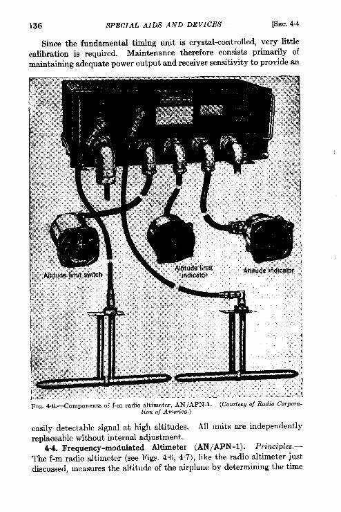
136 SPECIAL AIDS AND DEVICES [SEC.b-b
Since the fundamental timing unit is crystal-controlled, very littlecalibration is required. Maintenance therefore consists primarily ofmaintaining adequate power output and receiver sensitivity to provide an
FIG. 4.6.—Components of f-m radio altimeter, AN /APN-l. (Courte6g of Radio Corpora-tion of A77wrkz.)
easily detectable signal at high altitudes. All units are independentlyreplaceable without internal adjustment.
4.4. Frequency-modulated Altimeter (AN/APN-1). Principles.—The f-m radio altimeter (see Figs. 4“6, 4.7), like the radio altimeter justdiscussed, measures the altitude of the airplane by determining the time
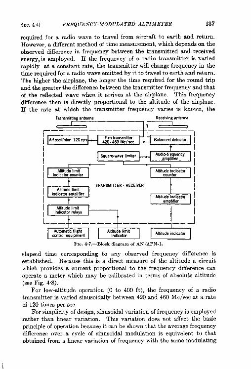
SEC.4.4] FREQUENCY-MODULATED ALTIMETER 137
required for a radio wave to travel from aircraft to earth and return.However, a different method of time measurement, which depends on theobserved difference in frequency between the transmitted and receivedenergy, is employed. If the frequency of a radio transmitter is variedrapidly at a constant rate, the transmitter will change frequency in thetime required for a radio wave emitted by it to travel to earth and return.The higher the airplane, the longer the time required for the round tripand the greater the difference between the transmitter frequency and thatof the reflected wave when it arrives at the airplane. This frequencydifference then is directly proportional to the altitude of the airplane.If the rate at which the transmitter frequency varies is known, the
Transmitting antenna ReceivingantennaI
t ),—— —. ——— ——— ——— ——. —..
/ lA.fosciitator ImcpsH F-m transmitter420-460 f#CISaC Balanced detector
I t
i,
ISquare-wavelimiter Aud:iofra#~y
P I
[ t TRANSMITTER-RECEIVER +
9Altltude indicatoramplifier
L—_+__. __+ ——— —.+_..
Fm. 4.7.—Block diagram of AN/APN-1.
elapsed time corresponding to any observed frequency difference isestablished. Because this is a direct measure of the altitude a circuitwhich provides a current proportional to the frequency difference canoperate a meter which may be calibrated in terms of absolute altitude(see Fig. 4.8).
For low-altitude operation (0 to 400 ft), the frequency of a radiotransmitter is varied sinusoidally between 420 and 460 Me/see at a rateof 120 times per sec.
For simplicity of design, sinusoidal variation of frequency is employedrather than linear variation. This variation does not affect the basicprinciple of operation because it can be shown that the average frequencydifference over a cycle of sinusoidal modulation is equivalent to thatobtained from a linear variation of frequency with the same modulating
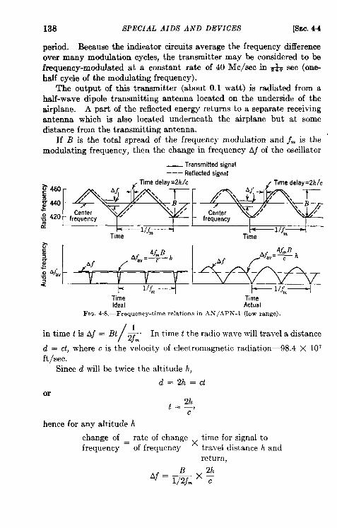
138 SPECIAL AIDS AND DEVICES [SEC. 4.4
period. Because the indicator circuits average the frequency differenceover many modulation cycles, the transmitter may be considered to befrequency-modulated at a constant rate of 40 Me/see in & sec (onc-half cycle of the modulating frequency).
The output of this transmitter (about 0.1 watt) is radiated from ahalf-wave dipole transmitting anterma located on the underside of theairplane. A part of the reflected energy returns to a separate receivingantenna which is also located underneath the airplane but at somedistance from the transmitting antenna.
If B is the total spread of the frequency modulation and j~ is themodulating frequency, then the change in frequency Af of the oscillator
_ Transmitted signal
––– Reflected sifmal
Time~me ~~~
Ideal Actual
FIG. 4.8.—Frequency-time relationa in AN /APN-l (low range).
/1
‘n ‘ime t ‘s ‘j = ‘t ~m”In time t the radio wave will travel a distance
d = CL,where c is the velocity of electromagnetic radiation—98.4 X 107ft/sec.
Since d will be twice the altitude h,
d=2h=ctor
hence for any altitude h
change of rate of change time for signal tofrequency =
xof frequency travel distance h and
return,
B
‘f = l/2jm—-x:
8EC. 4-4] FREQUENCY-MOD ULATED
or
4fmB ~.Aj=—c
ALTIMETER 139
On the low-range scale of AN/APN-1, fm = 120 cycles, B = 40Mc/sec, so that Afwillbe 19cycles per foot of altitude.
A signal frequency j., equal to the difference in frequency of thetransmitted and reflected waves, is derived by mixing in a balanceddetector a fraction of the transmitter output with the reflected wave, aspicked up on the receiving antenna. An audio sigrml of average fre-quency equal to 19 times the altitude in feet is obtained from this detector.
The actual instantaneous audio frequency varies periodically as shownin Fig. 4.8. It even goes to zero every time the oscillator frequency andthat of the reflected wave become equal (twice every cycle); as pre-viously mentioned, however, the indicating circuits average the signalfrequency over many modulation cycles.
This signal is amplified in the audio amplifier to a value equal to thehit level. The output consists of pukes, one for every cycle of theaudio signal. These pulses then operate a counting circuit which gener-ates a current proportional to the number of pulses per second. Thiscurrent passes through a meter which provides the altitude indication.
In order that the difference frequencies shall not become too high forthe pass band of the audio amplifier, when the high-altitude scale (O to4000 ft is used) B is reduced by a factor of 10 to 4 Me/see. Thus fA isreduced to 1.9 cycles per foot of altitude. An audio frequency nowcorresponds to ten times its previous altitude. Since the indicatingcircuit is virtually unchanged, the same indicating meter can be usedmerely by multiplying the scale by a factor of 10.
Separate circuits are provided for the attachment of an altitude limitindicator with three lights (“Above Altitude,” “At Altitude, ” “BelowAltitude”) for a pilot who wishes to fly at a fixed altitude. These cir-cuits can, if desired, be tied in to the automatic pilot to provide automaticcontrol of the aircraft altitude.
Chanwteristic.s.-AN/APN-l weighs 24* lb exclusive of cables andbrackets, which may weigh anywhere from 10 to 20 lb depending uponthe installation. The altimeter requires 70 watts at 27+ volts, DC.
Because of design considerations, the O-to-MOO-ft range scale mustnot be used below 400 ft. The low-range scale cannot be used as avernier to the high-range scale as it is in the pulsed altimeter.
Two sources of error are inherent in AN/APN-l: one is the so-called“fixed” error and the other the mushing error.
The source of the fixed error lies in the pulse-counting method ofobtaining a current proportional to altitude. The number of pulses per
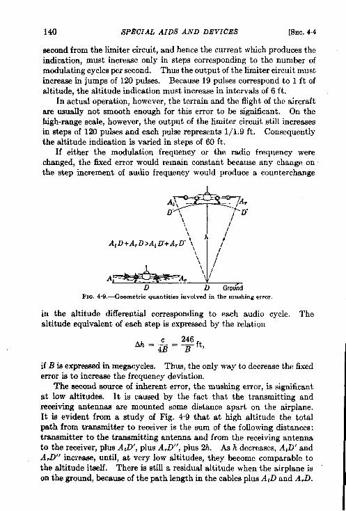
140 SPECIAL AIDS AND DEVICES [SEC. 44
second from the limiter circuit, and hence the current which produces theindication, must increase only in steps corresponding to the number ofmodulating cycles per second. Thus the output of the limiter circuit mustincrease in jumps of 120 pulses. Because 19 pulses correspond to 1 ft ofaltitude, the altitude indication must increase in intervals of 6 ft.
In actual operation, however, the terrain and the flight of the aircraftare usually not smooth enough for this error to be significant. On thehigh-range scale, however, the output of the limiter circuit still increasesin steps of EN pulses and each pulse represents 1/1.9 ft. Consequentlythe altitude indication is varied in steps of 60 ft.
If either the modulation frequency or the radio frequency werechanged, the fixed error would remain constant because any change onthe step increment of audio frequency would produce a counterchange
\\\\ h /
At D+ ArD>At LY+A,D” ‘I\\ /’\\ /
A,+Ar “~GK)”fii
Fm. 4.9.-@eometric quantities involved in the mushing error.
in the altitude differential corresponding to each audio cycle. Thealtitude equivalent of each step is expressed by the relation
Ah=&= yft,
if B is expressed in megacycles. Thus, the only way to decrease the fixederror is to increase the frequency deviation.
The eecond source of inherent error, the mushing error, is significantat low altitudes. It is caused by the fact that the transmitting andreceiving antennas are mounted some distance apart on the airplane.It is evident from a study of Fig. 49 that at high altitude the totalpath from transmitter to receiver is the sum of the following distances:transmitter to the transmitting antenna and from the receiving antennato the receiver, plus A,D’, plus A,D”, plus 2h. Ash decreases, A,D’ andA,D” increase, until, at very low altitudes, they become comparable tothe altitude itself. There is still a residual altitude when the airplane ison the ground, because of the path length in the cables plus AtD and A,D.
SEC. 4.5] COMPARISON OF F-M AND PULSED ALTIMETERS 141
As a result of this residual altitude an audi~frequency signal isdeveloped in the altimeter when the airplane is on the ground. Becausethe altimeter should read zero under such circumstances, it is calibratedto read zero when this audio frequency exists. At medium and highaltitudes, however, - since AtD + A,D > AtD1 + A,D”, this zero setcorrection is too great and the altimeter will read low. Within the low-altitude range, this error is minimized by altering the proportionalitybetween the indicating meter current and the audio frequency developed,no that the meter reads correctly at 300 ft as well as on the ground.Betw”een O and 300 ft, this effect can cause the altimeter to read low by asmuch as 5 ft in some installations.
In addition to these inherent errors operational errors, arising fromdrift of calibration, temperature or supply voltage changes, and so on,also exist. Ae a result, the error of AN/APN-l appears to be not greaterthan 5 ft + 5 per cent of the altitude on the low scale and 50ft + 5per cent of the altitude on the high scale. For a well-calibratedset, the altitude indication upon landing will most probably be within*5 ft.
AN/APN-l appears to hold calibration very well for periods of atleast a month. Special test equipment (TS-250/APN) is needed tocalibrate it. If a transmitter-receiver unit becomes defective it canbe replaced only by a unit calibrated for the same residual altitude.For a known installation this can be done at a test bench.
4.6. Comparison of F-m and Pulsed Altimeters.-It is evident thatthe f-m and pulsed altimeters, as they are designed at present, areintended for different purposes. The f-m unit has a very small fixederror; the puked altimeter haa a negligible percentage error. Bothmeasure the tme clearanm above the surface, but the f-m type is intendedfor very accurate height measurement at low altitudes, and thepulsed type is intended for less precise measurement up to very highaltitudes.
Each type performs its particular function well, but each could, atleast in principle, be adapted to serve both purposes. The f-m typecould be extended to higher altitudes without sacrifice of accuracy by theuse of a wider audio amplifier band and greater power output. Corre-spondingly, the accuracy of the puked type could be increased by the useof a shorter pulse (with appropriate increases in i-f and video bandwidth)and a shorter range scale for low-altitude measurement (perhaps a 500-ftscale).
The two types have very similar weight and power requirements.If no a-c supply is available, however, an inverter would be necessary tofurnish power for SCR-718C. The wartime cost of SCR-718C was $700while that of AN/APN-l was only $415,
142 SPECIAL Al DS AND DEVICES [SEC.4.6
The necessity for careful calibration of AN/APN-l means greaterdMiculties in maintenance than in the case of SCR-718C. In addition,as noted above, AN/APN-l transmitter-receivers are not readily replace-able unless similarly calibrated units are available. The meter presenta-tion of AN/APN-l seems definitely preferable to the cathode-ray tubepresentation of SCR-718C. The latter must be observed in reasonablydim light, whereas the meter can be placed in the cockpit dashboard.
4.6 Suggested Future Trends.—A single device with the range of thepulsed altimeter and the low-altitude accuracy of the f-m altimeter wouldbe a desirable improvement for future development. Meter presentationfor the pulsed altimeter could certainly be achieved by adoption of anyof a variety of existing range-tracking techniques, with little increasein weight.
If future applications require a decrease in the fixed error of the f-maltimeter, “an increase in the operating frequency would become desirableto permit the necessarily wider frequency deviation. In any shift to ahigher frequency, however, the radiated beam must not be made toonarrow or indications will be lost during banking or will be false duringsteep climbs or dives. Sharper beams than are used at present, however,would afford more accurate altitude information over rough terrain.
CHAPTER 5
SPECIAL DESIGN CONSIDERATIONS
BY D. HALLIDAY
Experience with airborne radar systems has shown that the simplicityof operation obtained by the reduction in the number and complexity ofcontrols nearly always results in improved usefulness. Nevertheless,it is often desirable to provide the operator with special devices or facil-ities which may be extremely valuable under certain restricted operatingconditions, although they are not essential. The radar designer mustevaluate the need for all special attachments and controls, balancingtheir usefulness against weight, power, and space limitations. No exactrules can be given because much depends upon the intended use of theradar system. This chapter describes some of the extra design featuresthat are often desirable, and discusses special receiver, indicator, andantenna problems associated with the design of airborne radar equipment.
5.1. Receivers. Autornutic Frequency Control, AFC.—Probably noother nonbasic design feature is so desirable as AFC which keeps the radarreceiver continually and automatically tuned to the frequency of thetransmitter. Commercial airborne radar receivers will almost cer-tainly incorporate it. AFC makes it possible for the receiver to followextremely rapid fluctuations in the frequency of the transmitter, causedby reflections of the radar pulses from the scanner housing or otherparts of the aircraft structure and usually synchronized with the rotationof the scanner. Such detuning is much more rapid than detuning causedby changes in pressure and in the temperatures of certain components ofthe radar system during search operation.
Two electronic AFC devices are commonly used for search and beaconoperation. In search operation the technique is to divert a tiny fractionof each transmitted puke into a circuit that measures the frequency.The electrical output of this circuit is used to alter the receiver tuningfrom pulse to pulse in order to keep it tuned at all times to the transmitterfrequency. Because a tuning correction is given by each pulse, the fre-quency to which the receiver is tuned is corrected hundreds of times persecond.
A special difficulty arises in beacon operation because the transmitterto which the radar receiver is to be tuned is located elsewhere-in the
143
144 SPECIAL DESIGN CONSIDERATIONS [SEC. 5.1
beacon. Dhect sampling of its frequency is impossible. Instead, acarefully constructed small hollow metallic cavity is installed as part ofthe beacon AFC equipment in the aircraft. It is resonant at a preciselychosen reference frequency. Circuits are arranged to keep the localoscillator of the receiver tuned to the frequency of this reference cavity.The frequency of the transmitter of the ground-based beacon is heldconstant with the aid of a similar reference cavity, the two frequen-cies differing by an amount equal to the intermediate frequency of thereceiver.
During beacon operation, AFC is most useful in the initial pickup atlong range. Beacon AFC usually permits instant pickup of the signal,whereas minutes might be required to find it by manual tuning becauseof the need for scanning. Once the signal has been observed, moreover,there is freedom from detuning caused by temperature drifts of the radarsystem.
Under conditions of perfect radar maintenance AFC should eliminatethe need for any manual tuning control. Experience has demonstrated,however, that present AFC circuits are so temperamental that the manualtuning control must be retained and a switch provided to transfer fromautomatic to manual tuning when necessary.
Three-tone Provisions.-It was pointed out earlier that the navigatorin an aircraft is interested in radar echoes from cities and other largetargets as well as in the weaker but more extensive echoes from the grounditself. Under some conditions, he will use low receiver gain in order toaccentuate the strong echoes from cities at the expense of those from thebackground of land. Sometimes he will use high gain to accentuaterivers, lakes, and other land-water boundaries. Because ordinaryreceivers and indicators do not allow clear distinction between the largeechoes from cities and the almost equally bright background of groundclutter, a device is needed to increase the contrast so that both classes ofsignals are displayed to good advantage on the PPI at one gain-controlsetting. Such electronic devices are known as “three-tone” circuits,the three” tones” being (1) the dark-noise background, (2) the somewhatlighter signal level from ground reflections, and (3) the bright signalsfrom cities and other large targets.
Figure 5.1 shows the advantage of using such a device. The improvedcontrast is apparent. These circuits also aid the recognition of detailwithin complex targets. Toward the close of the war, three-tone circuitswere being installed as field modifications of many military airborneradars. Three-tone circuits are useful because echoes seem to fall intotwo fairly separate groups of weak signals and strong signals.
There are several methods for attaining three-tone display; the onedescribed here uses two receivers differing in certain characteristics.
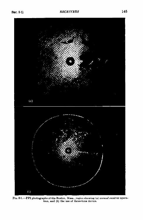
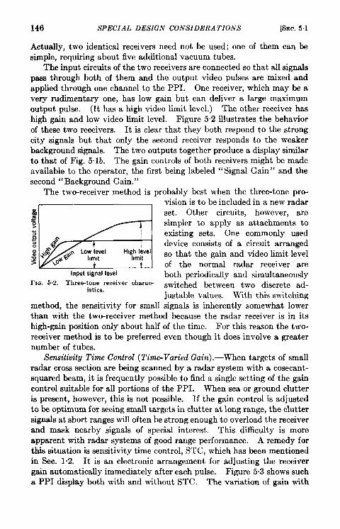
146 SPECIAL DESIGN CONSIDERATIONS [SEC. 5.1
Actually, two identical receivers need not be used; one of them can besimple, requiring about five additional vacuum tubes.
The input circuits of the two receivers are connected so that all signalspass through both of them and the output video pulses are mixed andapplied through one channel to the PPI. One receiver, which may be avery rudimentary one, has low gain but can deliver a large maximumoutput puke. (It has a high video limit level.) The other receiver hashigh gain and low video limit level. Figure 52 illustrates the behaviorof these two receivers. It is clear that they both respond to the strongcity signals but that only the second receiver responds to the weakerbackground signals. The two outputs together produce a dkplay similarto that of Fig. 5.lb. The gain controls of both receivers might be madeavailable to the operator, the first being labeled “Signal Gain” and thesecond “Background Gain. ”
The two-receiver method is probably best when the three-tone pro-
I
k?zzf5#input signal level
FIG. 5.2.—Three-tone receiver charac-istics.
method, the sensitivity for small
vision is to be included in a new radarset. Other circuits, however, aresimpler to apply as attachments toexisting sets. One commonly useddevice consists of a circuit arrangedso that the gain and video limit levelof the normal radar receiver areboth periodically and simultaneouslyswitched between two discrete ad-justable values. With this switchingsignals is inherently somewhat lower
than with the two-receiver method because the radar receiver is in itshigh-gain position only about half of the time. For this reason the two-receiver method is to be preferred even though it does involve a greaternumber of tubes.
Ssn.sditrity Tim Con.?rol (Time-Varied Gain) .—When targets of smallradar cross section are being scanned by a radar system with a cosecant-squared beam, it is frequently possible to find a single setting of the gaincontrol suitable for all portions of the PPI. When sea or ground clutteris present, however, this is not possible. If the gain control is adjustedto be optimum for seeing small targets in clutter at long range, the cluttersignals at short ranges will often be strong enough to overload the receiverand mask nearby signals of special interest. This difficulty is moreapparent with radar systems of good range performance. A remedy forthis situation is sensitivity time control, STC, which has been mentionedin Sec. 1.2. It is an electronic arrangement for adjusting the receivergain automatically immediately after each pulse. Figure 5.3 shows sucha PPI display both with and without STC. The variation of gain with
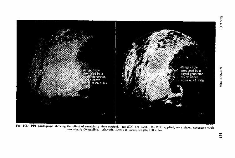
SE
C.5.1]
RE
CE
IVE
RS
147
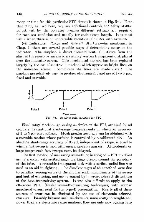
148 SPECIAL DESIGN CO.VSIDERA TIONS [SEC.5.2
range or time for this particular STC circuit is shown in Fig. 5.4. Notethat STC, as used here, requires additional controls and fairly skillfuladjustment by the operator because different settings are requiredfor each sea condition and usually for each sweep length. It is mostuseful when there is no appreciable variation of clutter with azimuth.
6.2. Indicators. Range and Azimuth Markers.—As mentioned inChap. 1, there are several possible ways of determining range on theindicator. The simplest is direct measurement of distance from thestart of the sweep by means of a suitably scribed transparent disk placedover the indicator screen. This mechanical method has been replacedlargely by the use of electronic markers which appear as bright lines onthe indicator screen. (Sometimes the lines are made dark.) Themarkers are relatively easy to produce electronically and are of two types,fixed and movable.
:t~
————- ---- —-— —-—— -.
‘: ,&$%
I t tPulse 1 Pulse 2 Pulse 3
Time —~lG. 5.4.—Iteceiver gain variation for STC.
Fixed range markers, appearing as circles on the PPI, are used for allordinary navigational slant-range measurements in which an accuracyof 2 to 5 per cent suffices. Much greater accuracy can be obtained witha movable marker whose position is controlled by a calibrated dial. Anabsolute slant-range accuracy of 25 yd, independent of range, is possiblewhen a fast sweep is used with such a movable marker. At moderate orlarge ranges such fast sweeps must be delayed.
The first method of measuring azimuth or bearing on a PPI involveduse of a collar with scribed angle markings placed around the peripheryof the tube. A rotatable transparent disk with a scribed radial line wasused as an aid in sighting. The disadvantages of this method were dueto parallax, zeroing errors of the circular scale, nonlinearity of the sweepand lack of centering, and errors caused by inherent azimuth distortionsof the data-transmitting system. It was also difficult to apply to theoff-center PPI. Similar azimuth-measuring techniques, with similarassociated errors, exist for the type-B presentation. Nearly all of thesesources of error can be eliminated by the use of electronic azimuthmarkers. Possibly because such markers are more costly in weight andpower than are electronic range markers, they are only now coming into
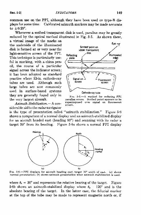
%c. 5.2] INDICATORS 149
common use on the PPI, although they have been used on type-B dis-plays for some time. Calibrated azimuth markers may be made accurateto ~ 0.25°.
Whenever a scribed transparent disk is used, parallax may be greatlyreduced by the optical method illustrated in Fig. 5.5. As shown there,a virtual image of the marks onthe underside of the illuminateddisk is formed at or very near thelight-sensitive screen of the PPI.This technique is particularly use-ful in marking, with a china pen-cil, the course of a particularsignal across the indicator screen;it has been adopted as standardpractice where 12-in. cathode-raytubes are used. Although suchlarge tubes are now commonlyused in surface-based systemsthey are generarly found only inthe very largest aircraft.
Azimuth Stabilization.—A con-siderable aid to the radar navigator
Eye
%ribed point on7
upper transparent /
F]Q. 5.5.—A method for reducing PPIparallax errors. Scribed point appears to bemperimposed over signal on fluorescentscreen.
is the type of presentation called “azimuth stabilization. ” Figure 5.6shows a comparison of a normal display and an azimuth-stabilized displayfor an aircraft headed east (heading 90°) and scanning with its radar atarget 30° from its heading. Figure 5.6a shows a normal PPI display
(a) (b]
Fm. 5.6.—PPI displays for aircraft heading east, target 30° south of east. (a) showsnormal presentation; (b) shows azimuth presentation when azimuth stabilization is used.
where 8, = 30° and represents the relative bearing of the target. Figure5.6b shows an azimuth-stabilized display where da = 120” and is theabsolute bearing of the target. In the latter case, the fiducial markerat the top of the tube may be made to represent magnetic north or, if
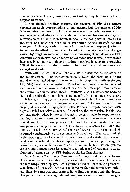
lbo SPECIAL DESIGN CONSIDERATIONS [SEC. 5.2
the variation is known, true north, so that 9. may be measured withrespect to either.
If the aircraft heading changes, the pattern of Fig. 5.6a rotatesthrough an angle corresponding to the change, but the pattern of Fig.5%b remains unaltered. Thus, comparison of the radar screen with amap is facilitated when azimuth stabdication is used because the map canautomatically be held with north in the 12 o’clock position beside theindicator and does not need to be reoriented as the aircraft headingchanges. It is also easier to use with overlays or map projection, atechnique described in Sec. 9.5. In addition, erratic heading changescaused by rough air motions do not cause smearing of signals on the PPI.Azimuth stabilization has so many advantages that it was incorporatedinto nearly all military airborne radars installed in airplanes weighing100,000 lb or more. It alao promises to be a useful adjunct to commercialnavigational radar.
With azimuth stabili.zation, the aircraft heading can be indicated onthe radar screen. The indication usually takes the form of a brightradial marker flashed upon the screen at the proper azimuth angle (seeFig. 5.6b) once each revolution. This flashing marker may be initiatedby a switch on the scanner shaft that is tripped once per revolution asthe scanner ie pointed dead ahead. Without such a marker, the headingcan be determined, but much less conveniently, from a magnetic compass.
It is clear that a device for providing azimuth stabilization must havesome connection with a magnetic compass. The instrument oftenemployed as standard equipment is the Pioneer Fluxgate compass witha gyro-leveled sensitive element. In outline, the mechanism is this: thecompass shaft, when it moves through a certain angle in response to aheading change, controls a motor that turns a rotation-sensitive com-ponent in the PPI sweep system through the same angle. Severalsweep-circuit components have this rotation characteristic. One fre-quently used is the rotary transformer or ‘‘ selsyn,” the rotor of whichis turned continuously by the scanner as it revolves. The stator, whichis clamped rigidly to the aircraft frame when azimuth stabilization is notused, can be rotated by thk compass-controlled motor, producing thedesired sweep azimuth displacements. In azimuth-stabilization systemsthe servomechanism must be capable of a high speed of response to avoidblurring of signals on the PPI during rapid heading changes.
Importance of Good Range Resolution.—An important factor in the useof airborne radar is the short time available for examining the detailsof short-range PPI displays. At a ground speed of 400 mph the presenta-tion displayed on a PPI with a 5-mile sweep changes completely withinless than two minutes and there is little time for examining the detailsof a pattern or for making detailed comparisons with a map. Recogni-
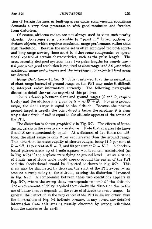
SEC. 5.2] INDICATORS 151
tion of terrain features or built-up areaa under such viewing conditionsdemands a very clear presentation with good resolution and freedomfrom distortion.
Of course, airborne radars are not always used to view such nearbyobjects. Sometimes it is preferable to “paint in” broad outlines ofdistant objects, which requires maximum range performance rather thanhigh resolution. Because the same set is often employed for both short-and long-range service, there must be either some compromise or opera-tional control of certain characteristics, such as the pulse length. Themost recently designed systems have two pulse lengths for search use-0.5 Paec when good resolution is required at close range, and 5.0 ~sec whenmaximum range performance and the mapping-in of extended land areasare desired.
Range Distortion.-In Sec. 3.1 it is mentioned that the presentationof slant range instead of ground range on the PPI may make it difficultto interpret radar information correctly. The following paragraphsdiscuss in detail the various aspects of thk problem.
The relationship between slant and ground ranges (S and R, respec-tively) and the altitude h is given by S = ~R2 + hz. For zero groundrange, the slant range is equal to the altitude. Because the nearestground target is usually the point directly below the airplane, it is clearwhy a dark circle of radius equal to the altitude appears at the center ofthe PPI.
The distortion is shown graphically in Fig. 5“7. The effects of intro-ducing delays in the sweeps are also shown. Note that at a great distanceS and R are approximately equal. At a distance of five times the alti-tude, the slant range is only 2 per cent greater than the ground range.This distortion increases rapidly at shorter ranges, being 11.5 per cent atR = 2H, 41 per cent at R = H, and 80 per cent at R = H/2. A checker-board pattern made up of l-mile squares would remain undistorted (asin Fig. 5.7b) if the airplane were flying at ground level. At an altitudeof 1 mile, an altitude circle would appear around the center of the PPIand the checkerboard would be distorted as shown in Fig. 5.7c. Thiscircle may be eliminated by delaying the start of the PPI sweep by anamount corresponding to the altitude, causing the distortion illustratedin Fig. 5.7d. A compromise between these two conditions appears inFig. 5.7e, where the sweep delay corresponds to one-half the altitude.The exact amount of delay required to minimize the distortion due to theuse of linear sweeps depends on the ratio of altitude to sweep range. Ingeneral, the distortion at the very center of the PPI is less important thanthe illustrations of Fig. 5.7 indicate because, in any event, any detailedinformation from this area ia usually obscured by strong reflectionsfrom the surface of the earth.
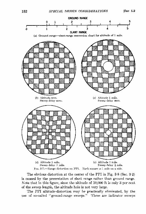
152 SPECIAL DESIGN CONSIDERATIONS [SEC 5.2
GROUND RANGE
01 2 3 4 5I I I I
r I I I T I I I I I 1
0 1 2 3 4 5
SLANT RANGE
(a) Ground rang-slant-range conversion chart for altitude of 1 mile.
(b) Altitude zero.Sweep delay zero.
(d) Altitude 1 mile.Sweep delay 1 mile.
(.) Altitude 1 miIe.Sweep delay zero.
(e) Altitude 1 mile.Sweep delay i mile.
FIQ. 57.-Range distortion on PPI. Each square IS 1 mile on a side.
The obvious distortion at the center of the PPI in Fig. 3.8 (Sec. 3.2)
is caused by the presentation of slant range rather than ground range.
Note that in this figure, since the altitude of 10,000 ft is only 3 per cent
of the sweep length, the altitude hole is not very large.The PPI altitude-distortion may be practically eliminated, by the
use of so-called “ground-range sweeps. ” These are indicator sweeps
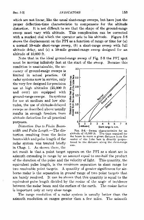
f+Ec.5.2] INDICATORS 153
which are not linear, like the usual slant-range sweeps, but have just the
proper deflection-time characteristic to compensate for the altitude
distortion. lt is not difficult to see that the shape of the ground-range
sweep must vary with altitude. This complication can be corrected
with a marked dial which the operator sets to his altitude. Figure 5.8
shows the displacement on the PPI as a function of range or time for (a)
a normal lo-mile slant-range sweep, (b) a slant-range sweep with full
altitude delay, and (c) a lo-mile ground-range sweep designed for an
altitude of 10,000 ft.
Note that in the ideal ground-range sweep of Fig. 5.8 the PPI spot
must be moving infinitely fast at the start of the sweep. Because this
condition is unattainable, the ac-curacy of ground-range sweeps islimited in actual practice. Of
radar systems now in service, only
the very few designed for precision
use at high altitudes (25,000 ft
and over) are equipped with
ground-range sweeps. In systems
for use at medium and low alti-
tudes, the use of altitude-delayed
sweeps as described above usually
results in enough freedom from
altitude distortion for all practical
purposes.Distortion Due to Finite Beam-
width and Pulse Length.-The dis-tortion resulting from the finite
beamwidth and pulse length of the
radar system was treated briefly
in Chap. 1. As shown there, the
“012345678l-AIStude+ Slant range in n.m.
FIG. 6. S.—Sweep characteristics for analtitude of 10,000 ft. The time required forthe beam to move a given distance from thecenter of the tube face is directly propor-tional to the distance along the slant-rangeaxis.
net result is that a point target appears on the PPI as a short arc in
azimuth extending in range by an amount equal to one-half the product
of the duration of the pulse and the velocity of light. This quantity, the
equivalent pulse length, is the minimum separation in slant range for
two resolvable point targets. A quantity of greater significance for air-
borne radar is the separation in ground range of two point targets that
are barely resolved. It can be shown that this quantity is equal to the
equivalent pulse length divided by the cosine of the angle of incidence
between the radar beam and the surface of the earth. The cosine factor
is important only at very close range.
The range resolution of a radar system is usually better than the
azimuth resolution at ranges greater than a few miles. The azimuth
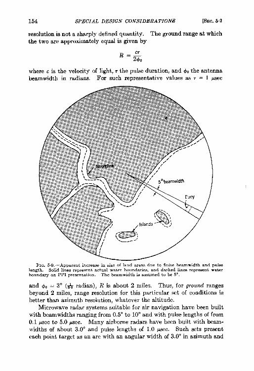
154 SPECIAL DESIGN CONSIDERATION@ [SEC.5.2
resolution is not a sharply defined quantity. The ground range at whichthe two are approximately equal is given by
where c is the velocity of light, r the pulse duration, and 410the antennabeamwidth in radians. For such representative values as 7 = 1 #see
)FIG 5.9.—Apparent increase in size of land areas due to finite beamwidth and pulse
length. Solid lines represent actual water boundaries, and dashed lines represent waterboundary on PPI presentation. The beamwidth is assumed to be 5“.
and ~0 = 3° (~ radian), R is about 2 miles. Thus, for ground rangesbeyond 2 miles, range resolution for this particular set of conditions isbetter than azimuth resolution, whatever the altitude.
Microwave radar systems suitable for air navigation have been builtwith beamwidths ranging from 0.5° to 10° and with pulse lengths of from0.1 psec to 5.o psec. Many airborne radars have been built with beam-widths of about 3.00 and pulse lengths of 1.0 psec. Such sets presenteach point target as an arc with an angular width of 3.0° in azimuth and
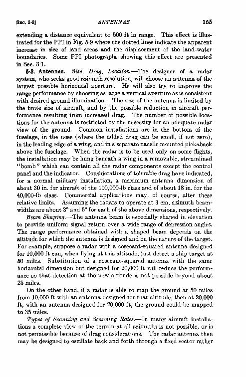
SM. 5.3] ANTENNAS 155
extending a distance equivalent to 500 ft in range. This effect is illus-trated for the PPI in Fig. 5“9 where the dotted lines indicate the apparentincrease in size of land areas and the displacement of the land-waterboundaries. Some PPI photographs showing this effect are presentedin Sec. 3.1.
6.3. Antennas. Size, Drag, Locution.-The designer of a radarsystem, who seeks good azimuth resolution, will choose an antenna of thelargest possible horizontal aperture. He will also try to improve therange performance by choosing as large a vertical aperture as is consistentwith desired ground illumination. The size of the antenna is limited bythe finite size of aircraft, and by the possible reduction in aircraft per-formance resulting from increased drag. The number of possible loca-tions for the antenna is restricted by the necessity for an adequate radarview of the ground. Common installations are in the bottom of thefuselage, in the nose (where the added drag can be small, if not zero),in the leading edge of a wing, and in a separate nacelle mounted pickabackabove the fuselage. When the radar is to be used only on some flights,the installation may be hung beneath a wing in a removable, streamlined“bomb” which can contain all the radar components except the controlpanel and the indicator. Considerations of tolerable drag have indicated,for a normal military installation, a maximum antenna dimension ofabout 30 in. for aircraft of the 100,000-lb class and of about 18 in. for the40,000-lb class. Commercial applications may, of course, alter theserelative limits. Assuming the radars to operate at 3 cm, azimuth beam-widths are about 3° and 5° for each of the above dimensions, respectively.
Beam Shaping.-The antenna beam is especially shaped in elevationto provide uniform signal return over a wide range of depression angles.The range performance obtained with a shaped beam depends on thealtitude for which the antenna is designed and on the nature of the target.For example, suppose a radar with a cosecant-squared antenna designedfor 10,000 ft can, when flying at this altitude, just detect a ship target at50 miles. Substitution of a cosecant-squared antenna with the samehorizontal dimension but designed for 20,000 ft will reduce the perform-ance so that detection at the new altitude is not possible beyond about25 miles.
On the other hand, if a radar is able to map the ground at 50 milesfrom 10,000 ft with an antenna designed for that altitude, then at 20,000ft, with an antenna designed for 20,000 ft, the ground could be mappedto 35 miles.
Types of Scanning and Scanning Rates.—In many aircraft installa-tions a complete view of the terrain at all azimuths is not possible, or isnot permissible because of drag considerations. The radar antenna thenmay be designed to oscillate back and forth through a fixed sector rather
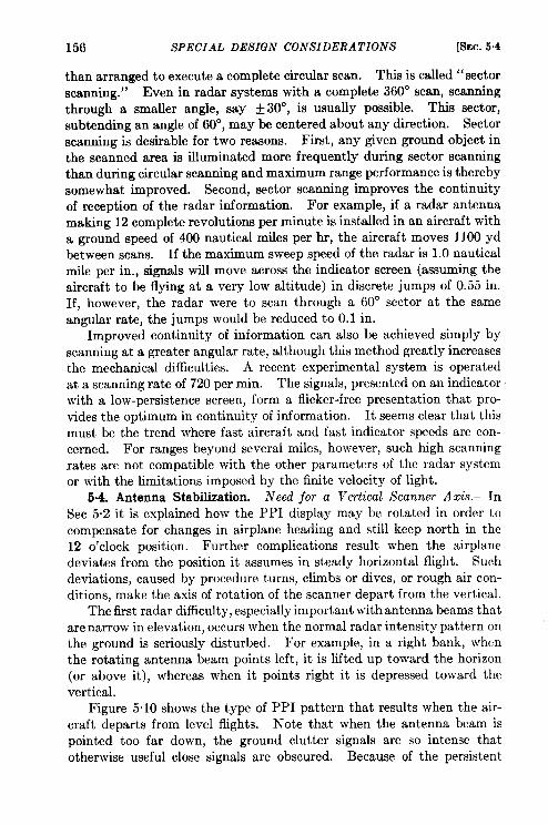
156 SPECIAL DESIGN CONSIDERATIONS [SEC. $4
than arranged to execute a complete circular scan. This is called “sectorscanning. ” Even in radar systems with a complete 360° scan, scanningthrough a smaller angle, say + 30°, is usually possible. This sector,subtending an angle of 60°, may be centered about any direction. Sectorscanning is desirable for two reasons. First, any given ground object inthe scanned area is illuminated more frequently during sector scanningthan during circular scanning and maximum range performance is therebysomewhat improved. Second, sector scanning improves the continuityof reception of the radar information. For example, if a radar antennamaking 12 complete revolutions per minute is installed in an aircraft witha ground speed of 400 nautical miles per hr, the aircraft moves 1100 ydbetween scans. If the maximum sweep speed of the radar is 1.0 nauticalmile per in., signals will move across the indicator screen (assuming theaircraft to be flying at a very low altitude) in discrete jumps of 0.55 in.If, however, the radar were to scan through a 60° sector at the sameangular rate, the jumps would be reduced to 0.1 in.
Improved continuity of information can also be achieved simply byscanning at a greater angular rate, although this method greatly increasesthe mechanical difficulties. A recent experimental system is operatedat a scanning rate of 720 per min. The signals, presented on an indicatorwith a low-persistence screen, form a flicker-free presentation that pro-vides the optimum in continuity of information. It seems clear that thismust be the trend where fast aircraft and fast indicator speeds are con-cerned. For ranges beyond several miles, however, such high scanningrates are not compatible with the other parameters of the radar systemor with the limitations imposed by the finite velocity of light.
5-4. Antenna Stabilization. Need jor a Vertical Scanner Axis.—InSec 5.2 it is explained how the PPI display may be rotated in order tocompensate for changes in airplane heading and still keep north in the1!2 o’clock position. Further complications result when the airplanedeviates from the position it assumes in steady horizontal flight. Suchdeviations, caused by procedure turns, climbs or dives, or rough air con-ditions, make the axis of rotation of the scanner depart from the vertical.
The first radar difficulty, especially important with antenna beams thatare narrow in elevation, occurs when the normal radar intensity pattern onthe ground is seriously disturbed. For example, in a right bank, whenthe rotating antenna beam points left, it is lifted up toward the horizon(or above it), whereas when it points right it is depressed toward thevertical.
Figure 5.10 shows the type of PPI pattern that results when the air-craft departs from level flights. Note that when the antenna beam ispointed too far down, the ground clutter signals are so intense thatotherwise useful close signals are obscured. Because of the persistent
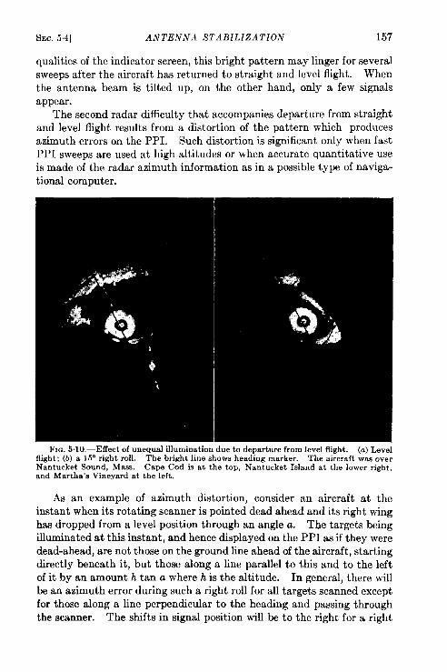
SEC. 5.4] ANTENNA STABILIZATION 157
qualities of the indicator screen, this bright pattern may linger for severalsweeps after the aircraft has returned to straight and level flight. Whenthe antenna beam is tilted up, on the other hand, only a few signalsappear.
The second radar difficulty that accompanies departure from straightand level fight results from a distortion of the pattern which producesazimuth errors on the PPI. Such distortion is significant only when fastPPI sweeps are used at high altitudes or when accurate quantitative useis made of the radar azimuth information as in a possible type of naviga-tional computer.
FIG. 5.10.—Effect of unequal illumination due to departure from Ievel flight. (a) Levelflight; (b) a 15° right roll. The bright line shows heading marker. The aircraft was over
Nantucket Sound, Mass. Cape Cod is at the top, Nantucket Island at the lower right,and Martha’s Vineyard at the left.
As an example of azimuth distortion, consider an aircraft at theinstant when its rotating scanner is pointed dead ahead and its right winghas dropped from a level position through an angle a. The targets beingilluminated at this instant, and hence displayed on the PPI as if they weredead-ahead, are not those on the ground line ahead of the aircraft, startingdirectly beneath it, but those along a line parallel to this and to the leftof it by an amount h tan a where h is the altitude. In general, there willbean azimuth error during such a right roll for all targets scanned exceptfor those along a line perpendicular to the heading and passing throughthe scanner. The shifts in signal position will be to the right for a right
158 SPECIAL DESIGN CONSIDERATIONS [SEC.6.4
roll, the exact azimuth error depending on both the range and azimuthof the target in question. No range errors are involved.
At an altitude of 25,000 ft, and with a ground-range sweep of 0.5nautical mile per in., the sideways shift of fore-and-aft signals on the PPIis about 0.4 in. during a 3° roll. Such displacement might be seriousunder special circumstances. However, for h = 10,000 ft, a = 3°, anda ground-range sweep speed of 1.0 nautical mile per in. the maximumsignal displacement is approximately 0.08 in., a negligible error forordinary navigational uses.
In commercial air service, the relatively few procedure turns and othermaneuvers can usually be anticipated; rough air motion is the mostcommon reason for departures from level flight. Continuous rough airmotions greatly reduce the usefulness of the radar and cause the indicatorscreen to resemble Fig. 5.10 much of the time. This is unfortunate sinceit is often precisely under these conditions that radar aid is most required.
Angular motions of the aircraft do not affect the accuracy of rangemeasurements, provided, of course, that the radar beam continues toilluminate the target.
Stabilization Requirenwnts.-lt is possible either to reduce greatlyor to eliminate both abnormal ground illumination and the patterndistortions by means of s~alled “ antennwstabilization” techniques.To evaluate the need for such stabilizing devices it is necessary to knowthe magnitude of roil and pitch to be expected during various fightconditions and the effect of such motions on ground illumination and onpattern distortion.
The angles of roll normally encountered are, on the average, about tentimes as large as pitch angles. Angular rates of roll are also considerablygreater than those of pitch. Hence, the problem is primarily one ofcorrecting for roll.
During coordinated turns, large roll angles develop. The roll angleduring such a turn is given by
tana=720~ti
where o is the true air speed in nautical miles per hour and w the turningrate of the aircraft in degrees per second. Thus, for an aircraft doing a30/see coordinated turn at a true airspeed of 250 nautical miles per hr, theroll angle is 30°.
One set of measurements of average rough-air motions has been madeby the National Advisory Committee for Aviation on a Lockheed trans-port of 55-ft wingspan. It was found that roll angles exceeded 10”during only 6 per cent of the flight time. These figures apply to averageair and were compiled under conditions in which the pilot attempted to
SEC. 5.4] ANTENNA STABILIZATION 159
fly a straight and level course. Clearly special operating conditions willcause wide departures from these figures.
Effects of pitch during turns and in rough air are usually small.Leveling difficulties may ~ccur, however, under special circumstances.In every aircraft there is a pair of level pads, small machined bosses soplaced that the line joining them is horizontal during level flight at ratedindicated air speed and for normal aircraft load. The radar scanner isinstalled so that its rotational axis is perpendicular to the line determinedby the level pads. Departures of the level-pad line from the horizontal,caused by climbs or dives, operation at other than standard indicated airspeed, and operation with other than standard loading, produces distor-tion of both the illumination and the apparent azimuth on the radar.A range of adjustment of 10° in the direction of the scanner axis can
) compensate for most of these departures from horizontal.The variations in pitch described above can be easily compensated for
by means of a screw so arranged that it can tilt the scanner base through+ 5° about an axis parallel to the wingspan line axis. This screw maybe operated manually with a flexible shaft either at the scanner or byremote control. The adjustment is made in flight, the criterion beingthat the ground clutter signals in the forward and rear sectors on thePPI appear equally bright. Automatic operation with a pendulum-con-
) trolled motor is also possible. Even though many aircraft now in servicedo not have leveling screws, they are a useful feature.
Methods of Stabilization.-The ideal solution to the problem of non-level flight would be to support the rotating antenna system in a doubleset of gimbals, driven in such a fashion that the scanner rotational axisalways remained vertical. This stable-base stabilization is relativelycostly in weight and is probably not justified for general commercialapplication. There are less costly approximate corrective devices whichperform quite adequately. Two of these, line-of-sight stabilization androll stabfization, are discussed below.
A need common to all stabilization schemes is a device for detecting\departures of the aircraft from level flight. A gimbal-supported gyro-scope provided with some self-erecting mechanism is nearly always used\for this purpose. It has the drawback that the erecting mechanism,which is purposely gravity-sensitive and acts so as to align the gyrospinaxis with the vertical during level flight, also responds to centripetalforces. During a protracted turn it will tend to pull the gyroaxis awayfrom the vertical and align it parallel to the resultant of gravity and thecentripetal acceleration. This effect, which is serious only in long turns,may be eliminated in some cases by disabling the erecting mechanismduring these turns.
The most common method of stabilization is called line-of-sight
160 SPECIAL DESIGN CONSIDERATIONS [sEC. 54
stabilization. Here the scanner base is fastened rigidly to the aircraft,and the beam is held pointed in the right direction by tilting the antennaas the scanner rotates. Thus if the right wing drops (right roll), theantenna must tilt upwards from its normal level flight position whenpointing to the right and downward when pointing left to maintainnormal ground illumination. when pointing fore or aft no tilt correctionis required. Thus one complete cycle of tilting per revolution must beaccomplished. For rapid-scanning or sector-scanning systems this canprove costly in terms of weight and power.
Ground illumination maintained by line-of-sight stabilization isadequate only for roll or for pitch. For combined roll and pitch, theillumination pattern departs somewhat from the normal. Because thescanner rotational axis actually leaves the vertical during maneuvers,PPI azimuth dktortions occur to the same extent as if no stabilizationwere used at all. These distortions can be partially compensated forby displacing the PPI pattern with the aid of electrical information fromthe gyro. The weight of present line-of-sight stabilizing equipment isabout 50 lb. for a 350-lb radar system.
Roll Stabilization.—A second method, which has been used only inexperimental installations, is roll stabilization. While it weighs moreand requires more space in the radome (for 360° coverage at least) thisscheme corrects perfectly when roll alone occurs. There is no provisionfor correction of pitch but, as has been pointed out, pitch effects canusually be neglected.
Roll stabilization, in its simplest form, is accomplished by suspendingthe scanner on trunnions so that it can be made to rotate about an axisparallel to that of the aircraft level-pad. When the aircraft is rolling,this rotatable scanner assembly is driven by a motor, deriving its exci-tation signal from the gyro. The motor has to operate only slowlyand infrequently in comparison with the tilt motor of line-of-sightstabilization.
Stabdization of antennas is a fairly recent development in airborneradar. The choice between roll stabilization and line-of-sight stabiliza-tion is difficult. In general, the cost of somewhat greater weight andradome size required by roll stabilization will be worth while only whencorrection of the azimuth distortion is important. Antennas of many ofthe radar systems now in service are not stabilized at all. Of those thatare, nearly all are stabilized in line-of-sight. Unstabilized radars includesystems developed before the advent of stabilization and more recents! ‘stems of small antenna diameter (broad antenna beam) designed forservice at medium and low altitudes. A complete discussion of antennastabilization will be found in Radar Scanrwm and Radomes, Vol. 26, Radia-tion Laboratory Series.
CHAPTER 6
ENGINEERING AND ECONOMIC CONSIDERATIONS
BY W. M. CADY, F. R. BANKS, JR., R. L. SINSHEIMER, D. HALLIDAY,AND H. FAHNESTOCK, JR.
6.1. Installation.l Scanner Installation and Radome Problems.—Theinstallation of the scanner presents a difficult problem. Some compro-mise which gives a good vantage point for viewing the ground, minimizesthe drag coefficient of the airplane, and at the same time makes thescanner easily accessible must be found.
The only position from which the scanner has a good 360° view isbeneath the fuselage. But in this location, too great a protrusion belowthe keel line adds to the aerodynamic drag. On the other hand, if theantenna is retracted too far, coverage is inadequate because the field ofradiation is partially blocked. The minimum protrusion allowable fromthe radar point of view in the prototype of each installation must bedetermined by measurements of the antenna pattern made with theantenna installed in a mockup. Such measurements have shown thatcertain recent scanning fanbeam antennas give satisfactory results if theyare installed so that nearly half their height is above the keel line of theairplane. These experimental results have been confirmed by observa-tions of the indicator in flight. Even in a belly installation, however,parts of the aircraft may cast shadows. Figure 6“1 shows the blankingof a part of the landscape caused by the partially retracted landing wheelsof a C-47 in which the equipment was installed. Similar blocking dueto the close approach of another aircraft is shown in Fig. 6.2.
The airborne scanner must be housed for protection against wind andweather. Its shelter is called the radome, and must be considered a partof the radar. The radome presents difficult problems of aerodynamics,transmission of electromagnetic waves, and structural design.
The aerodynamic problem arises because the antenna must protrudefrom the airplane; this requirement is probably most embarrassing in thecase of belly in~tallations. Antennas now in use must protrude somewhatmore than half their height (12 to 36 in. ) and the radome must protrudeenough to allow about an inch clearance as the antenna scans. Earlyradomes were cylindrical and not streamlined at all. They reduced the
LBy W, M. Cady.161
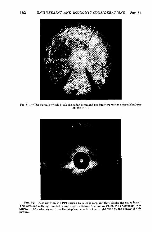
162 ENGINEERING AND ECONOMIC C!ONSIDERATIONS [SEC.6.1
F]~. 6.1 .—The aircraft wheelsblock the radar beam and produce two wedge-shapedshadowaon the PPI.
Fro..This airtaken.picture.
6.2.—A shadow on the ppI caused by a large airplane that blocks tbe radar beplane is flying just below and slightly behind the one in which the photographThe radar signal from the airplane is lost in the bright spot at the center of
earn.wasthis
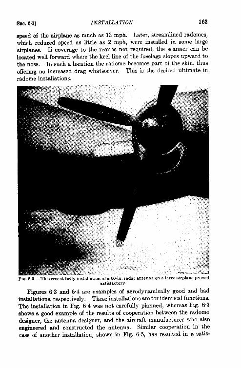
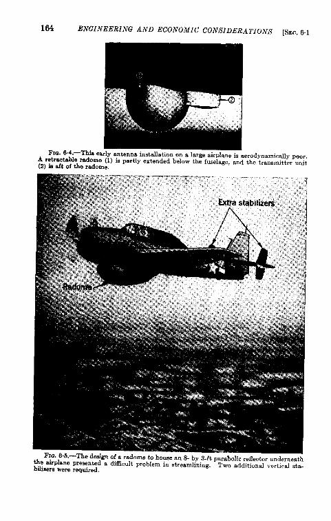
164 ENGINEERING AND ECONOMIC CONSIDERATIONS [SEC. 6.1
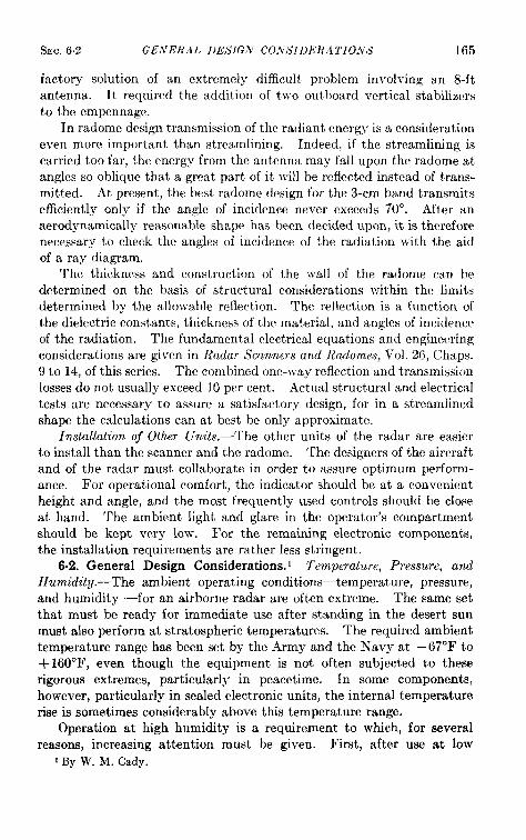
s~c, 6.2] GENERAL I)ESIG.\T CO.VSIDERA TIO.VS 165
factory solution of an extremply difficult problem involving an 8-ftantenna. It required the addition of two outboard vertical stabilizersto the empennage.
In raclome design transmission of the radiant energy is a considerationeven more important than streamlining. Indeed, if the streamlining iscarried too far, the energy from the antenna may fall upon the radome atangles so oblique that a great part of it will be reflected instead of trans-mitted. At present, the best radome design for the 3-cm band transmitsefficiently only if the angle of incidence never exceeds 70°. After anaerodynamically reasonable shape has been decided upon, it is thereforenecessary to check the angles of incidence of the radiation with the aidof a ray diagram.
The thickness and construction of the wall of the radome can bedetermined on the basis of structural considerations within the limitsdetermined by the allowable reflection. The reflection is a function ofthe dielectric constants, thickness of the material, and angles of incidenceof the radiation. The fundamental electrical equations and engineeringconsiderations are given in Radar Scanners and Radomes, Vol. 26, Chaps.9 to 14, of this series. The combined one-way reflection and transmissionlosses do not usually exceed 10 per cent. .4ctual structural and electricaltests are necessary to assure a satisfactory design, for in a streamlinedshape the calculations can at best be only approximate.
Installation of Other Units.—The other units of the radar are easierto install than the scanner and the radome. The designers of the aircraftand of the radar must collaborate in order to assure optimum perform-ance. For operational comfort, the indicator should be at a convenientheight and angle, and the most frequently used controls should be closeat hand. The ambient light and glare in the operator’s compartmentshould be kept very low. For the remaining electronic components,the installation requirements are rather less stringent.
6.2. General Design Considerations. 1 Temperature, Pressure, andHumiditq.—The ambient operating conditions—temperature, pressure,and humidity —for an airborne radar are often extreme. The same setthat must be ready for immediate use after standing in the desert sunmust also perform at stratospheric temperatures. The required ambienttemperature range has been set by the Army and the Navy at – 67°F to+ 160”F, even though the equipment is not often subjected to theserigorous extremes, particularly in peacetime. In some components,however, particularly in sealed electronic units, the internal temperaturerise is sometimes considerably above this temperature range.
Operation at high humidity is a requirement to which, for severalreasons, increasing attention must be given. First, after use at low
1By W. M, Cady.
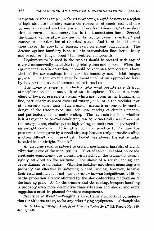
166 ENGINEERING AND ECONOMIC CONSIDERATIONS [SEC.6.2
temperature (for example, in the strat osphere), a rapid descent to a regionof high absolute humidity causes the formation of much frost and dewon mechanical and electrical parts. These formations may cause shortcircuits, corrosion, and energy loss in the transmission lines. Second,the diurnal temperature changes in the tropics cause “sweating” andconsequent deterioration of electrical parts. And third, humid condi-tions favor the growth of fungus, even on circuit components. Thedefense against humidity is to seal the transmission lines hermeticallyand to seal or “fungus-proof” the electrical components.
Equipment to be used in the tropics should be treated with any ofseveral commercially available fungicidal paints and sprays. When theequipment is not in operation, it should be kept at a temperature abovethat of the surroundings to reduce the humidity and inhibit fungusgrowth. The temperature may be maintained at an appropriate levelby leaving the heaters of vacuum tubes turned on.
The range of pressure in which a radar must operate extends fromatmospheric to about one-sixth of an atmosphere. The most notableeffect of lowered pressure is arcing, which may occur in the transmissionline, particularly at connectors and rotary joints, or in the modulator orother circuits where high voltages exist. Arcing is prevented by carefuldesign of the transmission line, adequate spacing of circuit elements,and particularly by hermetic sealing. The transmission line, whetherit is waveguide or coaxial conductor, can be hermetically sealed even atthe rotary joints; similarly, the high-voltage circuits can be packaged inan airtight container. It is rather common practice to maintain thepressure in some parts by a small airpump because truly hermetic sealingis often difficult and impractical. Sometimes almost the entire radaris sealed in an airtight “bomb.”
An airborne radar is subject to certain mechanical hazards, of whichvibration is one of the more serious. Most of the chassis that house theelectronic components are vibration-isolated, but the scanner is usuallyrigidly attached to the airframe. The shock of a rough landing cancause damage to the radar. Vibration isolators and shock mountings areprobably not effective in softening a hard landing, however, becausetheir total motion could not much exceed ~ in.—an insignificant additionto the protection already afforded by the shock-absorbing mechanism ofthe landing-gear. As for the scanner and the cabling, inexpert handlingis probably even more destructive than vibration and shock, and extraruggedness must be planned for these components.
Reduction oj Wc-ight.-Weight 1 is an extremely important considera-tion for airborne radar, as for any other flying equipment. Although the
1W. L. Myers, “Weight Analysis of Airborne Radar Sets,” RL Report No. 450,Jan. 1, 1945.
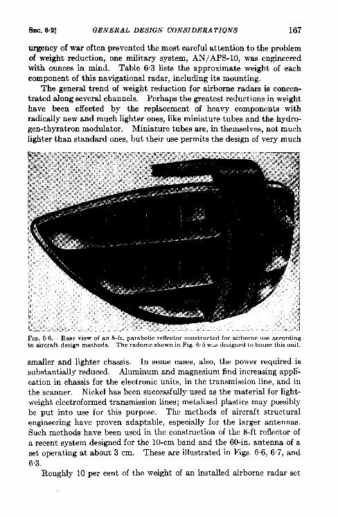
8~C. 6.2] GENERAL DESIGN CONSIDERATIONS 167
urgency of war often prevented the most careful attention to the problemof weight reduction, one military system, AN/APS-10, was engineeredwith ounces in mind. Table 6.3 lists the approximate weight of eachcomponent of this navigational radar, including its mounting.
The general trend of weight reduction forairborne radars is concen-tratedalong several channels. Perhaps thegreatest reductions in weighthave been effected by the replacement of heavy components withradically new and much lighter ones, like miniature tubes and the hydro-gen-thyratron modulator. Miniature tubes are, in themselves, not muchlighter than standard ones, but their use permits the design of very much
Fm. 66.-Rear view of an 8-ft. parabolic reflector constructed for airborne use accordingto aircraft design methods. The radome 6hown in Fig, 6.5 wus designed to house this unit.
smaller and lighter chassis. In some cases, also, the power required issubstantially reduced. Aluminum and magnesium find increasing appli-cat ion in chassis for the electronic units, in the transmission line, and inthe scanner. Nickel has been successfully used as the material for light-weight electroformed transmission lines; metalized plastics may possiblybe put into use for this purpose. The methods of aircraft structuralengineering have proven adapt able, especially for the larger antennas.Such methods have been used in the construction of the 8-ft reflector ofa recent system designed for the 10-cm band and the 60-in. antenna of aset operating at about 3 cm. These are illustrated in Figs. 6.6, 6.7, and63.
Roughly 10 per cent of the weight of an installed airborne radar set
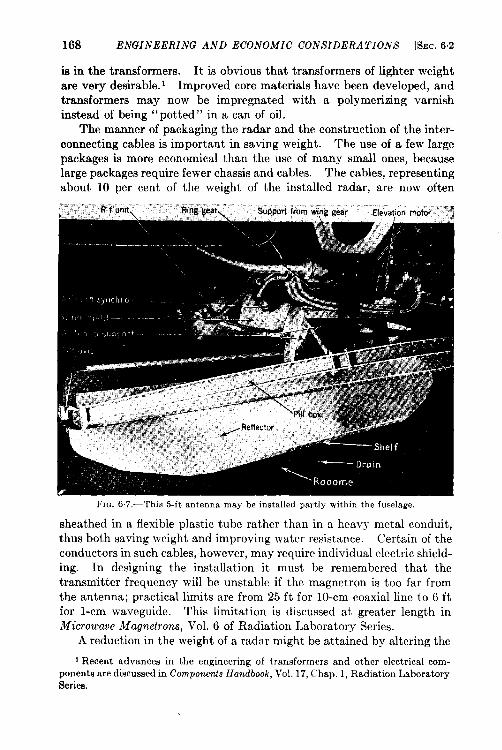
168 ENGINEERING AND ECONOMIC CONSIDERATIONS &C. 6,2
FIG. 6.7,—This 5-ft antenna may be installed partly within the fuselage.
sheathed in a flexible plastic tube rather than in a heavy metal conduit,thus both saving weight and improving water resistance. Certain of theconductors in such cables, however, may require individual electric shield-ing. In designing the installation it must be remembered that thetransmitter frequency will be unstable if the magnetron is too far fromthe antenna; practical limits are from 25 ft for 10-cm coaxial line to 6 ftfor l-cm waveguide. This limitation is discussed at greater length inMicrowave Magnetrons, Vol. 6 of Radiation Laboratory Series.
A reduction in the weight of a radar might be attained by altering the
1Recent advances in the engineering of transformers and other electrical com-ponents are discussed in Components Handbook, Vol. 17, Chap. 1, Radiation LaboratorySeries.
SEC. 6.2] GENERAL DESIGN CONSIDERATIONS 169
frequency and voltage of the power sources” now available. It is ques-tionable, however, whether frequencies higher than the nominal 400 cpsnow in use would be very effective because the saving in transformeriron might be offset by an increased weight of equipment for controllingthe voltage and the waveform. Voltages higher than the nominal 24volts d-c now used would allow reduction of the weight of the copper inthe cables.
Although the weight of existing radar sets ranges from 50 to as highas 500 lb, in redesign for peacetime use newer manufacturing practiceswill probably make possible a material reduction.
Primury Electm”calPower,-The power for operating an airborne radarcomes from generators mechanically driven by the aircraft engines.The requirements are for a small amount of d-c power at 27 volts and apreponderance of a-c at 115 volts and 400 to 800 CPS. For microwaveradar, the a-c load is usually in the range 1 to 3 kw. Some simple radardevices, such as altimeters and the like, require less than 100 watts.
Although the d-c generators now in use are fairly satisfactory, therigid insistence on light weight has prevented realization of both reliabil-ityy and satisfactory output characteristics in the a-c generators. Atpresent, heavy generators must be tolerated if the requirements of con-stant waveform and voltage (sometimes as strict as t 3 per cent) are tobe met despite reasonable variations in frequency (400 to 800 cps) and inload characteristics. Although a sinusoidal waveform is not essentialfor its own sake, generators which provide an extremely impure outputare also likely to produce an undesirable change in the waveform withchanges in load. In most installations the a-c power is still supplied byan inverter, but single-engine Navy airplanes have engine-driven gener-ators for both alternating current and direct current.
Electrical Noise Interference and Its Elimination. —’l’he radar maycause noise in the radio and intercommunication systems. Correctdesign and installation of both these and the radar system can greatlymitigate this disturbance. 1 Any wire that is not within a shieldedenclosure and carries high frequency or sharply varying current is apossible source of noise. Pickup may be prevented by: shielding orfiltering the leads of the communication systems; designing the radar toavoid, as far as possible, puked or high-frequency currents in long leads,and shielding the leads which must carry such currents; filtering at thenoise source within an offending unit; and providing adequate groundingof all shields and chassis to the airframe. Any spare wires in cables shouldbe grounded.
D-c motors are notorious sources of noise. At present, the usual cure
1Air Technical Service Command Technical Note TN-TSERR2-1, “Notes onDesign of Radar Systems Which do not Cause Radio Interference.”
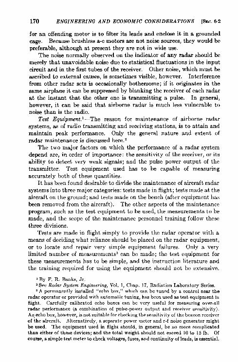
170 ENGINEERING AND ECONOMIC CONSIDERATIONS [SEC.6.2
for an offending motor is to ~ter its leads and enclose it in a groundedcage. Because brushless a-c motors are not noise sources, they would bepreferable, although at present they are not in wide use.
The noise normally observed on the indicator of any radar should bemerely that unavoidable noise due to statistical fluctuations in the inputcircuit and in the first tubes of the receiver. Other noise, which must beascribed to external causes, is sometimes visible, however. Interferencefrom other radar sets is occasionally bothersome; if it originates in thesame airplane it can be suppressed by blanking the receiver of each radarat the instant that the other one is transmitting a pulse. In general,however, it can be said that airborne radar is much less vulnerable tonoise than is the Iadio.
Test Equipment. ‘—The reason for maintenance of airborne radarsystems, as of radio transmitting and receiving stations, is to attain andmaintain peak performance. Only the general nature and extent ofradar maintenance is discussed here. 2
The two major factors on which the performance of a radar systemdepend are, in order of importance: the sensitivity of the receiver, or itsability to detect very weak signals; and the pulse power output of thetransmitter. Test equipment used has to be capable of measuringaccurately both of these quantities.
It has been found desirable to divide the maintenance of aircraft radarsystems into three major categories: tests made in flight; tests made at theaircraft on the ground; and tests made on the bench (after equipment hasbeen removed from the aircraft). The other aspects of the maintenanceprogram, such as the test equipment to be used, the measurements to bemade, and the scope of the maintenance personnel training follow thesethree divisions.
Tests are made in flight simply to provide the radar operator with ameans of deciding what reliance should be placed on the radar equipment,or to locate and repair very simple equipment failures. Only a verylimited number of measurements3 can be made; the test equipment forthese measurements has to be simple, and the instruction literature andthe training required for using the equipment should not be extensive.
I By F, R. Banks, Jr.2See Radar System Engineering, Vol. 1, Chap. 17, Radiation Laboratory Series.aA permanently installed “echo box, ” which can be tuned by a control near the
radar operator or provided with automatic tuning, has been used as test equipment inflight, Carefully calibrated echo boxes can be very useful for measuring over-allradar performance (a combination of pulse-pewer output and receiver sensitivity).An,echo box, however, is not suitable for checking the sensitivity of the beacon receiverof the aircraft. Alternatively, a separate power meter and r-f noise generator mightbe used. The equipment used in flight should, in general, be no more complicatedthan either of these devices; and the total weight should not exceed 10 to 15 lb. Ofcourse, a simple test meter to check voltages, fuses, and continuity of leads, is essential.
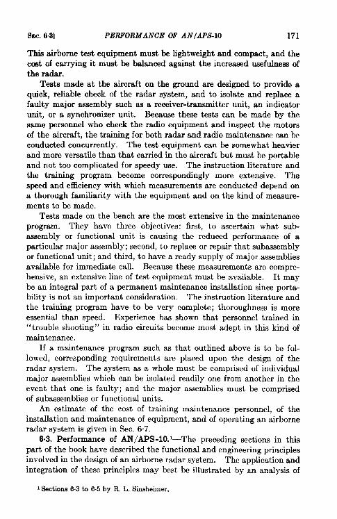
SEC. 6.3] PERFORMANCE OF AN/APS-10 171
This airborne test equipment must be lightweight and compact, and thecoat of carrying it must be balanced against the increased usefulness ofthe radar.
Tests made at the aircraft on the ground are designed to provide aquick, reliable check of the radar system, and to isolate and replace afaulty major assembly such as a receiver-transmitter unit, an indicatorunit, or a synchronizer unit. Because these tests can be made by thesame personnel who check the radio equipment and inspect the motorsof the aircraft, the training for both radar and radio maintenance can beconducted concurrently. The test equipment can be somewhat heavierand more versatile than that carried in the aircraft but must be portableand not too complicated for speedy use. The instruction literature andthe training program become correspondingly more extensive. Thespeed and efficiency with which measurements are conducted depend ona thorough familiarityy with the equipment and on the kind of measure-ments to be made.
Tests made on the bench are the most extensive in the maintenanceprogram. They have three objectives: first, to ascertain what sub-assembly or functional unit is causing the reduced performance of aparticular major assembly; second, to replace or repair that subassemblyor functional unit; and third, to have a ready supply of major assembliesavailable for immediate call. Because these measurements are compre-hensive, an extensive line of test equipment must be available. It maybe an integral part of a permanent maintenance installation since porta-bility is not an important consideration. The instruction literature andthe training program have to be very complete; thoroughness is moreessential than speed. Experience has shown that personnel trained in“trouble shooting” in radio circuits become most adept in this kind ofmaintenance.
If a maintenance program such as that outlined above is to be fol-lowed, corresponding requirements are placed upon the design of theradar system. The system as a whole must be comprised of individualmajor assemblies which can be isolated readily one from another in theevent that one is faulty; and the major assemblies must be comprisedof subassemblies or functional units.
An estimate of the cost of training maintenance personnel, of theinstallation and maintenance of equipment, and of operating an airborneradar system is given in Sec. 6.7.
6.3. Performance of AN/APS-10. ‘The preceding sections in thispart of the book have described the functional and engineering principlesinvolved in the design of an airborne radar system. The application andintegration of these principles may best be illustrated by an analysis of
1Sections6.3 to 6.5 by R. L. Sinsheimer.
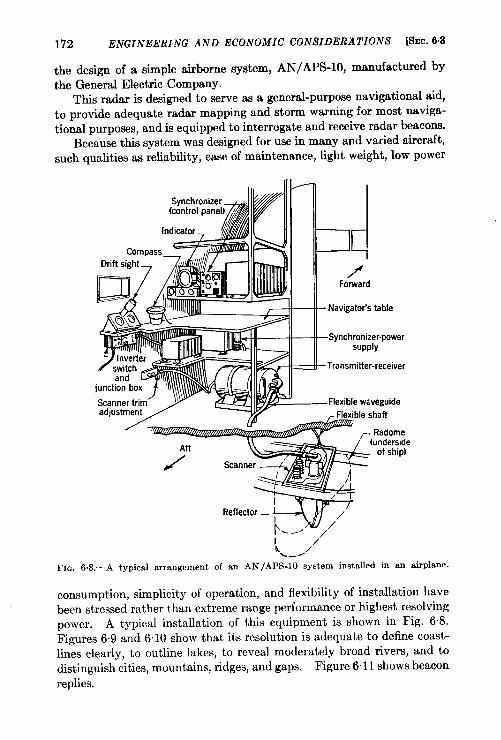
172 ENGINEERING AND ECONOMIC CONSIDERATIONS @JC. 6.3
the design of a simple airborne system, AN/APS-10, manufactured bythe General Electric Company.
This radar is designed to serve as a general-pu~ose natigatioml aid,to provide adequate radar mapping and storm warning for most naviga-tional purposes, and is equipped to interrogate and receive radar beacons.
Because this system was designed for use in many and varied aircraft,such qualities as reliability, ease of maintenance, light weight, low power
Fm.
/’Forward
5jil13Navigator’s table
SynchronizerPowersupply
. Transmitter-receiver
and
?
7
junction box ‘\\ \
Scanner trim Flexlble wiveguideadjustment Flexible shaft
Radome(underside
of ship)
~. ---
1/
/h /
=--
6.8.—A typical arrangement of an AN /APS-l O system installed in an airplane.
consumption, simplicity of operation, and flexibility of installation havebeen stressed rather than extreme range performance or highest resolvingpower. A typical installation of this equipment is shown in Fig. 6.8.Figures 6.9 and 6.10 show that its resolution is adequate to define coast-lines clearly, to outline lakes, to reveal moderately broad rivers, and todistinguish cities, mountains, ridges, and gaps. Figure 6“11 shows beacon
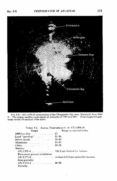
SEC. 6.3] PERFORMANCE OF AN/APSIO 173
FIG. 6.9.—AN/APS-lO presentation of the Chesapeake Bay area, Maryland, from 5600ft. The engine nacelles mask signals at azimuths of 100° and 260°. Pulse length 0.8 psec,range circles 10 nautical miles apart.
TABLE 61.-RANGE PERFOEMAWEOF AN/.kPS- 10Target
5000-ton ship.Land “painting”.Storm cloudsMountains.Cities . . . . .Beacons
AN/cPN-6Permanent ground installationAN/uPN-3.Semi-portableAN/uPN-4 .Portable
Range in nautical miles2525-3010-4025-3520-50
150 if not limited by horizon
At least 115 if not hmited by horizon
40-70
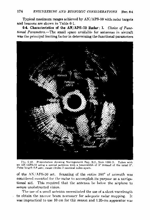
174 ENGINEERING AND ECONOMIC CONSIDERATIONS &m. 6.4
Typical maximum ranges achieved by AN/APS-10 with radar targetsand beacons are shown in Table 6.1.
6.4. Characteristics of the AN/APS-10 Radar: I. Choice of Func-tional Parameters.—The small space available for antennas in aircraftwas the principal limiting factor in determining the functional parameters
FIG. 610.-Presentat]on showing Narragansett Bay, R. I., from 1000 ft. Taken withrm AN /APS-10 using a special antenna with a heamwidth of 3° instead of the usual 5“.Pulse length 0.8 ~sec, range circles 2 nautical miles apart.
of the .4N/.4 PS-lO set. Scanning of the entire 360° of azimuth wasconsidered essential for the radar to accomplish its purpose as a naviga-tional aid. This required that the antenna be below the airplane tosecure unobstructed vision.
The use of a small antenna necessitated the use of a short wavelengthto obtain the narrow beam necessary for adequate radar mapping. Itwas impractical to use 10 cm for this reason and 1.25-cm apparatus was

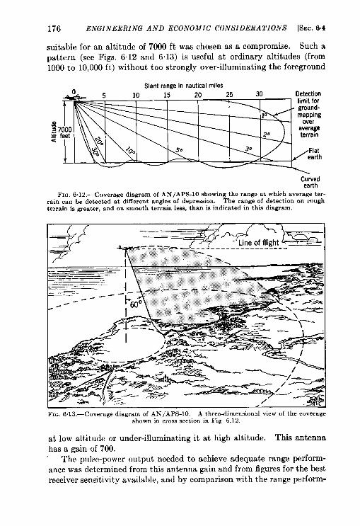
176 ENGINEERING AND ECONOMIC CONSIDERATIONS [SEC. 6.4
suitable for an altitude of 7000 ft was chosen as a compromise. Such apattern (see Figs. 6.12 and 6.13) is useful at ordinary altitudes (from1000 to 10,000 ft) without too strongly over-illuminating the foreground
Slant range in nautical miles
g=.-=<
C:aur:
FIG. 6.1 2.—Coverage diagram of AN /APS-10 showing the range at which average ter-rain can be detected at different angles of depression. The range of detection cm roughterrain is greater, and on smooth terrain less, than ie indicated in this diagram.
,—, ,
Fm. 6.13.—Coverage diagram of AN/APS-10. A three-dimensional view of the coverageshown in cross section in Fig 6.12.
at low altitude or under-illuminating it at high altitude. This antennahas a gain of 700.
The pulse-power output needed to achieve adequate range perform-ance was determined from this antenna gain and from figures for the bestreceiver sensitivityy available, and by comparison with the range perform-
8sIc. 6.4] CHARACTERISTICS OF THE AN/APS-10 RADAR 177
ante and parameters of existing systems. The calculations revealedthat a pulse-power output of 8 to 10 kw was necessary. Thk permittedthe use of a lightweight low-voltage transmitter—the 2J42 magnetron—and resulted in appreciable reduction in the weight, power consump-tion, and complexity of the modulator and modulator power suPplY ascompared with previous similar equipments.
Because of this low-power output and the small antenna, a stablereceiver of high sensitivity was required. As in most radar systems, asuperheterodyne receiver is employed. Reliability is improved by theuse of an AFC system for the local oscillator with a separate mixer forthe AFC channel.
The choice of other parameters, such as pulse-repetition frequency,PRF, and scan rate, depended on the requirements of coverage and rangeperformance. The PRF on search operation was limited by the timenecessary for each pulse to go to the maximum useful range and return,in addition to the time required for the indicator circuits to recoverbetween successive sweeps. This consideration led to a PRF of 810 persec. For beacon operation this value is halved so that the 2.2-ALsecpukelength necessary for beacon interrogation will not too drastically increasethe power requirements of the modulator above that of search operation.
This lower repetition frequency on beacon operation sets an upperlimit to the scan rate since several pulses, at least, must trigger the beaconeach time the beam sweeps by. In an aircraft traveling 4 to 6 miles perrein, only a few seconds can be allowed between successive scans in orderthat the range of nearby targets should not change too rapidly (see Sec.5.3.). As a compromise, a scan rate of 30 rpm was adopted. Thisprovides a look at each target every 2 sec and even at the lower repetitionrate five or six effective pulses per scan strike the beacon. 1
To provide reliable long-range beacon operation, every effort has beenmade to achieve a high receiver sensitivity for beacon signals. Auto-matic frequency control with a reference cavity is used to hold the localoscillator of the beacon to the proper frequency for the beacon reception.Video pulse stretching of the beacon signals (see Radar Beacons, Vol. 3,Sec. 2.3) is incorporated to enhance the brilliance of the beacon return onlong-range sweeps.
Presenkztion.-The PPI presentation, best for a navigational radarsystem, is employed in AN/APS-10. The M-S type is used because it islighter and gives more accurate azimuth data transmission than the M-Etype, and does not require the precise mechanical construction needed
1only half the pulsesincidentuponthe beaconareeffectivebecausethe frequencyrangeto whichthe beacon (AN/CPN-6) is sensitiveis rapidly switchedbetweentwohands. Thic is done in order tQcover the wide rangeof frequenciesused for 3-cmairborneradar.
178 ENGINEERING AND ECONOMIC CONSIDERATIONS [SEC. 64
for the M-M type. (See Sec. 1.8 for a discussion of these three methodsof deflecting the beam.)
The choice of range sweeps closely follows the operational capabilitiesof the sydem. An adjustable sweep, continuously variable from 4 to25 miles, is provided for the operator’s convenience in following thetarget. A 50-mile sweep allows the detection of cities beyond the generala-ma of land mapping. Extra O- to 90- and 70-to 160-mile beacon sweepsare provided to take advantage of the ability of the system to pick updistant beacons. The range marks provided are those most convenientto the operator. The specifications for the sweep lengths and rangemarks are shown in Table 6.2.
TABLE 6.2.-SWEEP LENGTHSAND RANGE MAFtKSUSED IN AN/APS-10Sweeprangesin miles Range marks
0-4 to &14 (continuouslyvariable). . . . . . . . . . every 2 miles0-15 to O-25 (continuouslyvariable)
}. . every 10 miles
and G50O-90and 70-160. . . . . . . . . . . . . . . . . . . . . . . . . . . . . . . . . ..every20 miles
A tube face with a diameter of 5 in. was the smallest that could be usedto provide a picture easily interpreted by the operator. The restrictedspace in aircraft prohibited the use of a larger tube. The persistence ofthe cathode-ray tube was chosen to match the scan rate by providing amap that neither faded between scans nor blurred after the second scan.For the avoidance of blurring a P-14 was found to be preferable to a P-7phosphor.
To combat unfavorable ambient light conditions, cathode-ray tubesgiving high light intensity are employed, but for many installations—andespecially for any cockpit installation for a pilot—a visor is necessary forobserving the tube.
There is usually an indicator at the navigator’s position in an aircraft.For some installations, however, it is desirable that the pilot also have anindicator. For this purpose full provisions for a second, remote indicatorare included.
Operation.-Considerable effort was expended to simplify the operat-ing controls of AN/APS-10 and to make them virtually foolproof.
There are four frequently used and four infrequently used operatingcontrols, and two more that are primarily for the operator’s convenience.The four commonly used controls are:
1. A RaWe Selector Sun”tchto select the scale of the radar map dis-played on the PPI.
2. A Receiver Gain Control to obtain information about the relativestrength of the radar targets and to bring out terrain detail other-wise hidden.
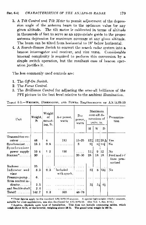
SEC. 6.4] CHARACTERISTICS OF THE AN/APS-10 RADAR 179
3.
4.
A Tilt Control and Tilt Meter to permit adjustment of the depres-sion angle of the antenna beam to the optimum value for anygiven altitude. The tilt meter is calibrated in terms of altitudein thousands of feet to serve as an appropriate guide to the properantenna depression for maximum coverage at any given altitude.The beam can be tilted from horizontal to 18° below horizontal.A Search-Beacon Switch to convert the search radar system into abeacon interrogator and receiver, and vice versa. Considerableinternal complexity is required to perform this conversion by asimple switch operation, but the resultant ease of beacon oper-ation justifies it.
The less commonly used controls are:
1. The Ofl-On Switch.2. The Focus Control.3. The Brilliance Control for adjusting the over-all brilliance of the
PPI picture to the best level relative to the ambient illumination.
TAZLE6 3.—WEIGHTS,DIMENSIO~S,ANDPOWEII REQUIREMENTS OF AN/APS-10
LTnit
Transmitter-re-ceiver
Synchronizer. . .Synchronizer
power supplyScanner*.
Radome. . . . . . . .Indicator and
visorPressurepump.Trim control in-
dicator.and flexibleshaftTotal. . . . . . . . .
k’eightlb
4613.1
19 420
258.3
6,
2.52.4
142.7
rVeightof
nount-ng, lb,
40.8
12
0:3
6:3
A-c power, D-c
watts power,watts
185 15–25
3
150
30:50
ncludedwith synch,
.Maximumover-all di-mensions of
units, in.
H w D
12: 12; 20&
9: 6: 14*
11+ 9 1228 18 18
6: ““8“ iii”
L ““
3; 5* 4+
Pressuriza-tion
YesNo
NoFeed and r-flines pres-surized
No
* These figuresSDDIYto the standard AN/A PS-10~camer. A special lightweight (13-lb.) wanner,suitable for mast applications, wanalso developed for AN/A PS-10. (See Vol. 1, Sec. 9.12.)
f Approx., depends upon type of inatrdlation. This does not include connecting cables, whichwolgh about 12 lb, or the inverter, weighing about 28 lb. The grand total weight in 189 lb.
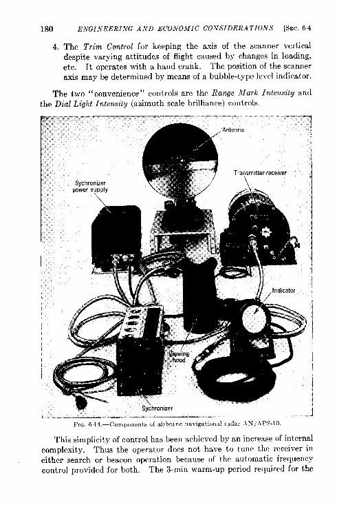
180
4.
ENGINEERING AND ECONOMIC CONSIDERA TKONS [SEC. 6,4
The Trim Control for keeping the axis of the scanner vertical
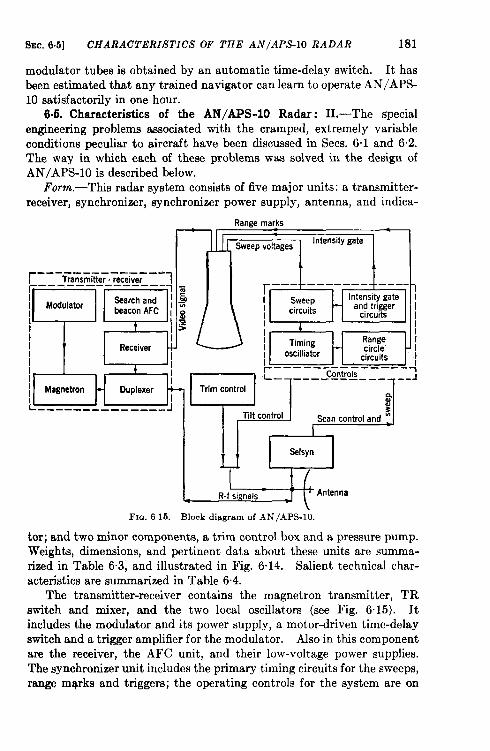
SEC. 6.5] CHARACTERISTICS OF THE AN/APS-10 RADAR 181
modulator tubes is obtained by an automatic time-delay switch. It hasbeen estimated that any trained navigator can learn to operate AN/APS-10 satisfactorily in one hour.
6.5. Characteristics of the AN/APS-10 Radar: 11.—The specialengineering problems associated with the cramped, extremely variableconditions peculiar to aircraft have been discussed in Sees. 6.1 and 6.2.The way in which each of these problems was solved in the design ofAN/APS-10 is described below.
Fomn.—Thk radar system consists of five major units: a transmitter-receiver, synchronizer, synchronizer power supply, antenna, and indica-
Range marks
[’hSweep voltages
Intensity gate
r --. -— —— —--—---
~__ flE’Emitier, receiver ~
!Ta
ModulatorSearch and ~
/ beacon AFC 1III
Receiver
[!--.—---_—_____
I I
J==J--iAntenFm. 6 15.—Block diagram of AN/APS-10.
tor; and two minor components, a trim control box and a pressure pump.
Weights, dimensions, and pertinent data about these units are summa-
rized in Table 6.3, and illustrated in Fig. 6.14. Salient technical char-
acteristics are summarised in Table 6.4.
The transmitter-receiver contains the magnetron transmitter, TR
switch and mixer, and the two local oscillators (see Fig. 6.15). It
includes the modulator and its power supply, a motor-driven time-delay
switch and a trigger amplifier for the modulator. Also in this component
are the receiver, the AFC unit, and their low-voltage power supplies.
The synchronizer unit includes the primary timing circuits for the sweeps,
range mqrks and triggers; the operating controls for the system are on
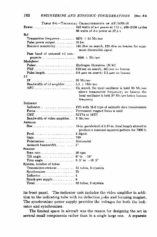
182 ENGINEERING AND ECONOMIC CONSIDERATIONS [SEC.6.5
TABLE 6.4.—TECHNICAL CEIAEACTERISTICSOF AN/APS-10Power . . . . . . . . . . . . . . . . . . . . . . . . . . 340 watts of a-c power at 115 v, 400-2400 cycles
SOwatts of d-c power at 27.5 vRf
Transmitter frequency. . . . . . . . . 9375 ~ 55 Me/seePulse power output..,......,.. 10kwReceiver sensitivity. .,. ... . . . . 131 dbw on search, 125 dbw on beacon for mini-
mum discernible signalPass band of untuned r-f com-
ponents . . . . . . . . . . . . . . . . . . . . . 92SO+hfc/secMod;latar
Puller. . . . . . . . . . . . . . . . . . . . . . . .PRO. . . . . . . . . . . . . . . . . . . . . . . . .Pulselength. . . . . . . . . . . . . . . . . .
I-fIF.,..,, . . . . . . . . . . . . . . . . . . . . .Bandwidthof i-f amplifier.. . . .AFT,.. ,, . . . . . . . . . . . . . . . . . . .
IndicatorIndicator. . . . . . . . . . . . . . . . . . .Focus . . . . . . . . . . . . . . . . . . .CRT..Bandwidthof video amplifier.
AntennaSize. . . . . . . . . . . . . . . . . . . . . . . . . .
Feed. . . . . . . . . . . . . . . . . . . . . . . . .Gain. . . . . . . . . . . . . . . . . . . . . . . . .Polarization. . . . . . . . . . . .Azimuthbeamwidth. .
ScannerScan rate. . . . . . . . . . . . . . . . . . . . .Tilt angle...,. . . . . . . . . . .Triangle., .,.,.,.. . . . . .
System,numberof tubesTransmitter-recewer. . .,Synchronizer. . . . . . . . . . . . . . . . . .Indicator. . . . . . . . . . . . . . . . . . . . .Synch-pwrsupply. . . . . . . . . . . . .Total ...,..,.. . . . . . . . . . .
Hydrogen thyratron (3C45)810/sec on search; 405/see on beacon0.8 @ec on search; 2,2.psec on beacon
30 Me/see5.5 f lMc/secOn search the local oscillator is held 30 Me/see
above transmitter frequency; on beacon tbelocal oscillator is held 30 Mc /see below beaconfrequency
PPI with M-S type of azimuth date transmissionPermanent magnet focus is used5FP14 or 5FP73 Mc /see
13-in, paraboloid of 5.67-in. focal length altered toproduce a cosecant-squared pattern for 7000 ft
2 dipole700Horizontal5°
30 rpm0° to –18”6.5°to –10,5”
31 tubes, 3 crystals254666 tubes, 3 crystals
its front panel. The indicator unit includes the video amplifier in addi-tion to the indicating tube with its deflection yoke and focusing magnet.The synchronizer power supply provides the voltages for both the indi-cator and synchronizer.
The limited space in aircraft was the reason for designing the set inseveral small components rather than in a single large one. A separate
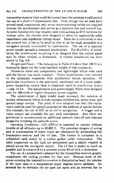
SEC. 65] CHARACTERISTICS OF THE AN/APS-10 RADAR 183
transmitter-receiver that could be located near the antenna would permitthe use of a short r-f transmission line. Even though the set does haveseveral small components only seven interconnecting cables are requiredbecause the synchronizer also serves as a junction box and control box.As some installations may require cable runs as long as 25 ft between thevarious units, the circuits were designed to allow for appreciable cablecapacitance and significant voltage drops. Since the synchronizer is alsothe control box, it has to be small so that it can be made accessible to anavigator already surrounded by instruments. The use of a separatepower supply permits a compact synchronizer. For flexibility of instal-lation the synchronizer mounting is so designed that the control panelmay be either vertical or horizontal. A typical installation has beenshown in Fig. 6.8.
Weight and Power.—The data given in Table 6.3 show that 189 lb is areasonable figure for the total installed weight of this equipment.
Miniature tubes and components and lightweight alloys were usedand the layout was made compact. Power requirements were reducedto the minimum consistent with satisfactory circuit operation. Ofparticular importance is the previously mentioned use of a lower pulse-power magnetron output than is commonly used by search-type radars—only 10 kw. The transformers and power-supply filters were designedonly for 400-cycle or higher-frequency power supplies.
The achievement of light weight made necessary the omission ofcertain refinements which include antenna stabilization, sector scan, andground range sweeps. The point of view adopted was that this equip-ment could be used for special purposes by the addition of special devices(for example, the use of GPI as an aid to navigation). A trigger and avideo output are available for any such attachment. Also there areprovisions to accommodate an additional azimuth take-off and externalmeans for reversing the azimuth motor.
Operating Conditions. -AN/APS-lO is expected to operate withouttrouble at all altitudes up to 30,000 ft. The potential dangers of arcingand of condensation of water vapor are eliminated by pressurizing the
“ transmitter-receiver and the r-f line. The former is contained in acylindrical tank sealed by a rubber gasket under compression. Thecable connectors on the tank are pressurized and a plastic window isplaced across the waveguide output. The r-f line is sealed as much aspossible and is connected to a pressure pump fitted with a desiccator.
The use of a pressurized container for the transmitter-receiver greatlycomplicates the cooling problem for that unit. Because most of thepower entering the transmitter-receiver is dissipated as heat, the interiorof the tank rises to a temperature many degrees above ambient. Aninternal fan to circulate the air past hot spots and an external fan to
184 ENGINEERING AND ECONOMIC CONSIDERATIONS [SEC.6.5
maintain a steady stream of air over the container combine to reduce therise above ambient to 35°C. Because, however, this system is requiredto operate indefinitely at 50”C and to withstand an hour’s operation at7l“C, the internal components had to be carefully selected to permitoperation at temperatures close to 100”C. Oversize resistors andpotentiometers and plastics that would not weaken were selected.
At the other extreme are the very low operating temperatures encoun-tered at high altitudes; the set is expected to operate satisfactorily at– 55”C. To insure proper operation over this extreme range of tempera-ture, wire-wound resistors and capacitors having predictable temperaturecoefficients are used for many of the circuits. The reference cavity forbeacon AFG is made of invar. Special lubricants are used that will not,
cause fan and scanner motors to freeze up at —55°C, and that will not be
too thin at 71°C. Rubber bellows and the like are of a type that ~vill
not crack at — 55°C.
The components are designed to withstand, despite their light weight,,
the severe conditions of vibration and shock encountered in aircraft.
This is accomplished by shock-mounting all components cxccpt the
antenna and trim box. Where possible, as in the transmitter-receiver,
the center-of-gravity type of shock mount is used. Shock-mounting is
impractical for the antenna which must be made sufficiently rugged to
withstand vibration. pressurized flexible waveguide is used to conduct
the radar energy from the shock-mounted transmitter-receiver to the
rigidly mounted antenna.
Primary Power Supply.—In order to minimize the effects of thevariations in frequency and waveform of aircraft power, rectifier suppliesof the full-wave choke-input type are used. Power transformers havebeen carefully designed to avoid resonances throughout the frequencyregion of 400 to 2400 cps. Electronically regulated power supplies havebeen used where necessary to maintain exact voltages or to remove thelow-frequency ripple found in the output of many aircraft inverters.
IVoise Elimination.—All units are grounded to the airframe; cablesand fan blades are shielded. Filters have been inserted in the powerleads to fan motors, antenna motors, and all circuits capable of generatingr-f energy.
Maintenance.-The contemplated variety and wide dispersion ofAN/APS-10 installations made the maintenance problem exceedinglydMicult. A defective unit should be quickly replaceable. From thispoint of view the presence of several radar boxes both simplified andcomplicated replacement. Small units We easier to remove and toreplace, but the defective unit must first be identified.
For ease of maintenance all units have been made independentlyreplaceable with no need of adjustments. Within the transmitter-
SEC.6.6] TYPICAL PERFORMANCE OF EXISTING SYSTEMS 185
receiver, the individual functional units are built upon aubchawis, whichcan easily be removed by undoing a few screws and internal connectors.The receiver and AFC units are so complex that no attempt to repairthem should be made in the field. They should be returned to majordepots for repairs.
External test points have been provided on the transmitter-receiverand synchronizer power supply to aid in identifying a defective unit.On the transmitter-receiver, these include a test trigger from the modu-lator, an extra video channel, and a lead to a directional coupler incor-porated within the transmitter-receiver. On the synchronizer powersupply, pin jacks are provided at which the power-supply voltages canbe measured. Further convenient test points are incorporated on manyof the subchassis of the transmitter-receiver unit.
These external test points, combined with a routine procedure ofinspection, permit maintenance to detect incipient failure and to ensurepeak performance.
Future Trends.-AN/APS-lO was designed during 1944. Althougha few modifications have been made, its design has remained substantiallyunchanged. Improvements in the radar field since 1944 suggest that aredesign taking full advantage of existing techniques 1 would result inappreciable improvement of range performance, resolution, and relia-bility. More specifically, an increase in range performance of perhaps 20per cent, a decrease in weight of perhaps 25 per cent, and an improvedreliability and ease of maintenance could be attained with improvedcomponents and techniques.
This system has been selected for detailed analysis as representativeof a large class of general navigational-radar systems. Airborne radarhas many functions, however, and has taken many other forms to fulfillthem. Some of the more characteristic of these are described briefly inthe following section.
6s6. Typical Performance of Some Existing Systems.~The systemsdescribed below are offered as a selection from existing equipments thatillustrate the radar performance that results from typical choices of basicdesign parameters. Systems with considerable field service as well asrecently developed laboratory prototypes are included so that trendscan be observed. The listing is in chronological order of developmentand includes only developments made in the United States. Attentionis given chiefly to navigational functions that have commercial applica-tion although all were designed for military purposes. Table 6.5 con-tains a r&um6 of some fundamental design parameters of each of these
‘~. L. Sinsheimer, “A Final Report on AN/APS-10,” RL Report No. 874, March 1,1946.
i By D. Halliday.
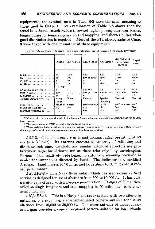
186 ENGINEERING AND ECONOMIC CONSIDERATIONS [%c, 6.6
equipments; the symbols used in Table 6.5 have the same meaning asthose used in Chap. 1. An examination of Table 6.5 shows that thetrend in airborne search radars is toward higher power, narrower beams,longer pulses for long-range search and mapping, and shorter pulses whengood discrimination is required. Most of the PPI photographs of Chap.3 were taken with one or another of these equipments.
TABLE65.-SOME DESIGNCHARACTEIUSTICSOFAIHROENERADARSYSTEMS
ASS-3
A, cm . . . . . . . . . . . . . . . . . . . . . 54G, . . . . . . . . . . . . . . . . . . . . . . 11P,. kw . . . . . . . . . . . . . . . . . . . . 5Di n., . . . . . . . . . . . . . . . . . . . 24
(array,,* fisec., putw length. 2PRF, taps. . .,,..,.,. 400O,degrees . . . . . . . . . . . . . . . . . 4.5Typical imte.llation, Wing
edgeScan type. . . . . . . . . . . . . . . . . ManualStabilized ~cnnner?. NoInstalled weight,%lb.
AN/APs-3
3.227004018
1
3Noe.e
sectorNo
AN/APS-15 AN/APQ-?
3.22 A22800 or 1200 150040 5029 190
1-1 or 0.5 0.4650 or 1010 400 or 160C3 0.4Ventral Special
housing360” or sector + 30°Yen No370 775
AN/APQ-13with largeantenna
3.2211303560
0.5,1.131350,6241.3”Ventral
360° or aectoNo500
Rapidscan I
1.254orm2429
0,1660001.0Ve”tnal
360°No350
* Mo8t of the radaraheredescribed also have a 2-uuecpuke and a .uitable repetition rate for beaconinterrogation.
t The lower value of PRF is used with the large value of r.~ These weights include cables but not the primary power auPPIY. In certain case. they include
the weight of npecificmilitary equipment such 88 bombing computem.
ASB-3.—This is an early search and, homing radar, operating at 58cm (515 Me/see). Its antenna consists of an array of reflecting anddirecting rods since parabolic and similar extended reflect ora are pro-hibitively large for airborne use at these relatively long wavelengths.Because of the relatively wide beam, no automatic scanning provision ismade; the antenna is directed by hand. The indicator is a modifiedA-scope. Land masses to 70 miles and large ships to 30 miles are stand-ard performance.
AN/APS-3.—This Navy 3-cm radar, which has seen extensive fieldservice, is designed for use at altitudes from 500 to 10,000 ft. It has onlya sector type of scan with a B-scope presentation. Ranges of 80 nauticalmiles on single freighters and land mapping to 50 miles have been com-monly attained.
AN/APS-15.—This ii a Navy 3-cm radar system with two alternateantennas, one providing a cosecant-squared pattern suitable for use ataltitudes from 10,000 to 36,000 ft. The other antenna of higher maxi-mum gain provides a cosecant-squared pattern suitable for low-altitude
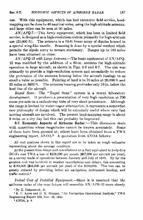
SEC.6.7] ECONOMIC’ ASPECTS OF AIRBORNE RADAR 187
use. With this equipment, which has had extensive field service, la.nd-rnapping can be done to 40 nautical miles, using the high-altitude antenna,and large cities can be seen at 90 miles.
AN/APQ-7.—This Army equipment, which has been in limited fieldservice, is designed as a high-resolution system primarily for high-altitudeuse (25,000 ft). The antenna is a 16-ft linear array of dipoles housed ina special wing-like nacelle. Scanning is done by a special method whichpermits the dipole arr~y to remain stationary. Ranges up to 160 mileshave been obtained on cities.
AN/APQ-13 m“thLarge Antenna.—The basic equipment of AN/APQ-13 was modified by the addition of a 60-in. antenna for high-altitudeoperation in large aircraft, as shown in Figs. 63 and 6.7. The aim wasprimarily to provide a high-resolution system and secondarily to reducethe protrusion of the antenna housing below the aircraft fuselage to assmall a value as possible. Painting of land is to 70 miles at 20,000 ft and35 miles at 5000 ft. The antenna housing protrudes only 10 in. below thekeel line of the aircraft.
Rap”d Scan.—The “Rapid Scan” system is a recent laboratorydevelopment. It produces a presentation of very high resolution at 700scans per min on a cathode-ray tube of very short persistence. Althoughthe range is limited by water-vapor attenuation, it represents a somewhatnew philosophy of design which will be extremely useful where very fastmoving aircraft are involved. The present land-mapping range is about9 miles on a dry day but this can probably be improved.
6.7. Economic Aspects of Airborne Radar. -This discussion dealswith quantities whose magnitudes cannot be known accurately. Someof them have been guessed at; others have been obtained from a TWAengineering report, ANOA.2 A quotation from AhTOA follows:
All cost analyses shown in thk report are to be taken as rough estimatesrepresenting about the average condition.
At the presenttime delays and cancellations on a fleet equivalent to forty-fiveDC-3’s cost TWA a loss of $250,000 per month [$67,000 per aircraft per year],on a survey made of operations between January and July of 1945. By far thegreatest cost was involved in weather cancellations and delays, this amountingto $165,000 [$44,000 per aircraft per year] of the $250,000. This loss can begreatly reduced by providing better air navigation, instrument landing, andtraffic control.3
Initial Cost oj Installed Equipment. —Since it is assumed that theairborne radar of the near future will resemble AN/APS-10 more closely
I By H. Fahnestock, Jr.z R. C. Ayres and H. K. Morgan, “ Air Navigation Operational Analysis,” TWA
Engineering Report 650, Nov. 10, 1945.1ANOA, p. 4.
188 ENGINEERING AND ECONOMIC CONSIDERATIONS [SEC.6.7
than it will any other present set, the specifications for this system areused as a basis for the discussion.
In January 1945 the airlines of the United States were operatingbetween 500 and 600 aircraft, and it is expected that this number willincrease to about 1000 by 1947. If airborne radar is to be used at allon the domestic airlines, it is to be expected that several hundred installa-tions will be made. The Army Air Forces had an order during the warfor 5000 AN/APS-10 units at $8000 each. Balancing the smallerpeacetime numbers against peacetime economies of production it wouldappear that this figure, also assumed by ANOA, will cover the price ofthe equipment plus the cost of installation. If the set were depreciatedover a period of five years, the cost of depreciation would amount to$1600 per aircraft per year. If very careful planning were done inadvance, it should take a four-man crew about three days to install thesystem.
Cosk oj Flying, Operation, and Maintenance. —Unless otherwisestated, all further cost figures are for one aircraft per year. From ANOAwe learn that it costs $30 per year to fly one pound of extra equipment.Other airlines find that this cost may be $200. The total installed weightof AN/APS-10, with all necessary auxiliary equipment, is about 190 lb.In addition, because the radome drag may reduce cruising speed by 3mph, in order to maintain the same margin of safety in range, a DC-3must carry 60 lb of extra fuel on a 6-hr flight, and a DC-4 170 lb on a10-hr flight.
Both-a radio operator and a navigator are now normally part of thecrew of a large ship in international service, and the radar set would beoperated by one of these-probably the navigator. If the crew consistsonly of a pilot and a copilot, as in a DC-3, the equipment would beoperated by the copilot. AN/APS-10 was designed with this in view.
In neither case is an extra crew member needed, but those who dooperate the set must be given special training, about 25 hours on a groundtrainer, followed by studies of oscilloscope photographs. The operatorshould then have some 20 hours’ further work in the air on oscilloscopeinterpretation. Many former radar navigators in the Army Air Forcesare now available who would need very little further training to qualifyas civilian air navigators. This subject is discussed in greater detail inSec. 3.3.
Maintenance would logically be done by the present radio mainte-nance personnel after additional training. An experienced aircraft radio-man would require about 6 months’ schooling in general radar principlesand in servicing AN/APS- 10. But here again experienced men areavailable from the Army Air Forces.
The maintenance work could be done in existing radio repair shops
SEC. 6.7] ECONOMIC ASPECTS OF”AIRBORNE RADAR 189
if they were provided with special radar test equipment and supplies ofspare parts. The time that the aircraft is grounded for radar mainte-nance should not exceed that for the radio maintenance, but actuaUy thenumber of man-hours necessary would be somewhat greater simplybecause of the greater complexity of equipment and the short life of cer-tain special tubes. In ANOA it is stated that maintenance costs of theradar are $600 per year.
Ground Beucons.-The capabilities of the radar set cannot be fullyrealized unless beacon stations are established. It is not expected thattheir costs will fall upon the airlines; more probably some governmentagency such as the Civil Aeronautics Authority would install and main-tain them, just as it now does visual beacons and other ground accessoriesto flight. Nevertheless the matter is mentioned here for completeness.
During the war 1000 ground-based beacons (AN/CPN-6) wereordered by the Navy at $30,000 apiece. About half this figure repre-sents the cost of the beacon alone and the remainder is the cost of anabundant supply of spare parts. These beacons were more powerfulthan would be necessary or desirable for the application under discussion.Let us assume that each beacon and its spare parts maybe purchased for$20,000; allow $10,000 more for the purchase or lease of a site and theconstruction of a road, power line, and equipment shelter. Let us furtherassume that one man can maintain 3 beacons and their spares at a costof $6000 a year. The initial cost per beacon station would then amountto $50,000, or $5000 per year if amortized over a 10-year period. Thecost of maintenance would increase this figure to an annual cost of $7000per beacon station.
When two beacons are placed at each location the spare could bearranged to turn on whenever the first beacon failed. The response ofeach beacon could have some peculiar characteristic by which an airplaneobserver could identify that particular beacon.
TAZLE 6.6
IA, $Soflb peryr I At $100/HJ per ~~I
DC-3 DC-4 DC-31
DC-4
l—l—Cost of equipment amortized over 5-yr
period . . . . . . . . . . . . . . . . . . . . . . $1,600 $ 1,600Cost of flying 190 lb of equipment. 5,700 5,700Cost of flying extra fuel; 6-hr trips on DC-3,
l@hron DC-4 . . . . . . 1,800 5,100Maintenance . . . . . . . . . . . 600 600Cost to airline per year per airplane. 9,700 13,000
$ 1,60019,000
6,000
600
27,200
$ 1,600
19,000
17,000600
38,200

190 ENGINEERING AND ECONOMICAL CONSIDERATIONS [~EC: 6.7
Net Cost and Savings.—The above costs to an airline per airplane peryear are tabulated for a DC-3 and a DC-4 using two values for dollarsper pound per year in Table 6.6.
There are no figures in ANOA which correspond directly with these.There is one of $12,440, the greater part of which is radar cost, but itincludes the cost of some other equipment as well. The above costs areto be compared with expected decreased costs of $28,000, about one-halfof which can be fairly ascribed to the use of radar equipment. 1
If dollars were the sole consideration it appears that there would beno particular advantage in installing AN/APS- 10 in commercial aircraft.However, the increase in good will and respect for air travel which wouldgo hand-in-hand with progressive increases in safety and dependabilitymight far outweigh the foregoing economic considerations.
1ANOA, pp. 24, 30.
PART III
GROUND-B.4SED RADAR

–——
——
...
——
CHAPTER 7
TYPES OF GROUND-BASED RADAR AND SPECIAL EQUIPMENT
BY NI. A. CHAFFEE, J. S. HALL, H. B. ABAJIAN, H. P. STABLER,
G. C. COMSTOCK, A. G. EMSLIE, J. B. PLATT, R. IW WHITMER,
J. L1. STURTEVANT, AND R. H. I’IULLER
SEARCH AND AUTOMATIC-TRACKING RADARS
The following two chapters are intended to gi~c the reader insightinto the problem of air traffic control and landing. The basic n~viga-tional aids required for a reasonable solution of this problem may be usedin any one of many possible forms. The rather heterogeneous collectionof aids described in this chapter are molded into several possible patternsin the chapter that follows.
7.1. A Long-range Microwave System. ‘There appears to be apeacetime need for a radar set with long range and high resolution whichshould be able to deal with large numbers of aircraft, give a completeover-all picture of the air traffic, and permit detailed examination of theactivity in a small selected area. High resolution would allow aircraftflying close together to be seen separately on the PPI and would reducethe possibility of target confusion due to ground signals.
Let us first pursue the line of thinking which a radar designer wouldprobably follow if he were to design a long-range microwave ground-basedradar.
Specifications. -Thespecifications of such a microwave radar may besummarized briefly as follows. It should be capable of detecting a singlefour-engined airplane above the horizon up to an altitude of 30,000 ftand out to a range of about 200 miles. The rate of scan is 4 rpm; atleast 15 pulses per scan should strike each target. Resolution in rangeand azimuth should be as high as is compatible with these specificationsfor range and rate of scan.
An inspection of a coverage diagram such as that shown in Fig. 7“6indicates that two separate antenna systems might be used. The long-range system would produce a single lobe with a vertical spread of 3°.If the axis of this lobe were elevated 1° above the horizontal, such a beamwould satisfy the range-height specification at low elevation angles. Theshort-range antenna system must have a beam that is fanned at least 25°
1By M. A. Chaffee and J. S. Hall.193
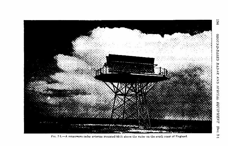
194G
RO
UN
D-B
AS
ED
RA
DA
RA
ND
SP
EC
IAL
EQ
UIP
ME
NT
[SEC.
71
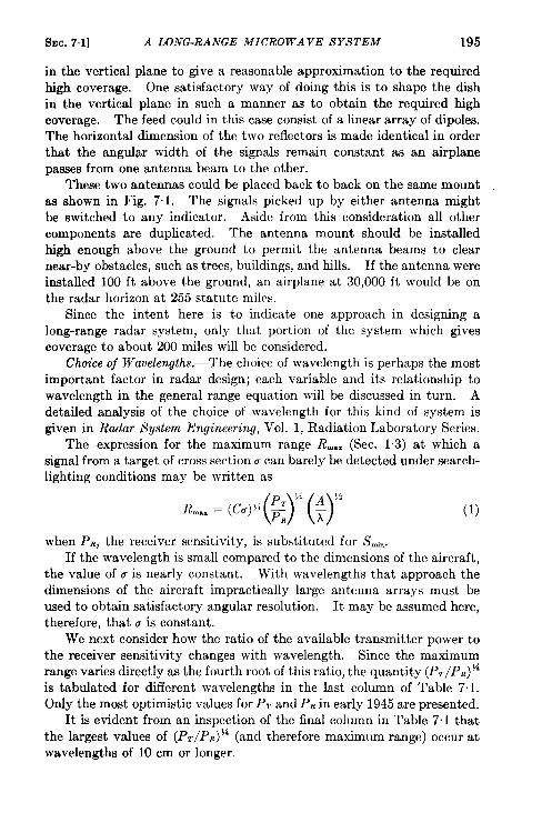
SEC. 7.1] A LONG-RANGE MICROWAVE SYSTEM 195
in the vertical plane to give a reasonable approximation to the requiredhigh coverage. One satisfactory way of doing this is to shape the dishin the vertical plane in such a manner as to obtain the required highcoverage. The feed could in this case consist of a linear array of dipoles.The horizontal dimension of the two reflectors is made identical in orderthat the angular width of the signals remain constant as an airplanepasses from one antenna beam to the other.
These two antennas could be placed back to back on the same mountas shown in Fig. 7.1. The signals picked up by either antenna mightbe switched to any indicator. Aside from this consideration all othercomponents are duplicated. The antenna mount should be installedhigh enough above the ground to permit the antenna beams to clearnear-by obstacles, such as trees, buildings, and hills. If the antenna wereinstalled 100 ft above the ground, an airplane at 30,000 ft would be onthe radar horizon at 255 statute miles.
Since the intent here is to indicate one approach in designing along-range radar system, only that portion of the system which givescoverage to about 200 miles will be considered.
Choice oj WaoeleWths.—The choice of wavelength is perhaps the mostimportant factor in radar design; each variable and its relationship towavelength in the general range equation will be discussed in turn. Adetailed analysis of the choice of wavelength for this kind of system isgiven in Radar System Engineering, Vol. 1, Radiation Laboratory Series.
The expression for the maximum range R~,. (Sec. 1.3) at which asignal from a target of cross section u can barely be detected under search-lighting conditions may be written as
R~==(c”’%)($
(1)
when P~, the receiver sensitivity, is substituted for A’ti.If the wavelength is small compared to the dimensions of the aircraft,
the value of u is nearly constant. W“ith wavelengths that approach thedimensions of the aircraft impractically large antenna arrays must beused to obtain satisfactory angular resolution. It may be assumed here,therefore, that u is constant.
We next consider how the ratio of the available transmitter power tothe receiver sensitivity changes with wavelength. Since the maximumrange varies directly as the fourth root of this ratio, the quantity (P,/PR) ‘iis tabulated for different wavelengths in the last column of Table 7.1.Only the most optimistic values for P. and P, in early 1945 are presented.
It is evident from an inspection of the final column in Table 7.1 thatthe largest values of (P~/P~) ‘i (and therefore maximum range) occur atwavelengths of 10 cm or longer.
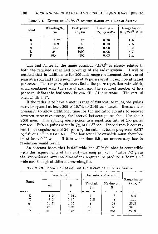
196 GROUND-BASED RADAR AND SPECIAL EQUIPMENT [SEC. 7.1
TAHLE 7.1.—EFFEcT OF (PT/PR)% ON THE RANGE OF A RADAR SYSTEM
Band Wavelength, Peak power Recvr. sens. Range factorcm PT., kw P., w watts (PT/Pfl) J{ x Iof
K 1,25 25 0.20 1,9
x 3.2 50 0.13 2.5
s 10.7 1000 0.08 6.0
L 25 1000 0.05 6.7P 100 500 0.03 6.4
The last factor in the range equation (A/x)}i is closely related toboth the required range and coverage of the radar system. It will berecalled that in addition to the 200-mile range requirement the set mustscan at 4 rpm and that a minimum of 15 pulses must hit each point targetper scan. The range requirement limits the pulse repetition rate which,when combined with the rate of scan and the required number of hitsper scan, defines the horizontal beamwidth of the antenna. The verticalbeam width is 3°.
If the radar is to have a useful range of 200 statute miles, the pulsesmust be spaced at least 200 X 10.74, or 2148 psec apart. Because it isnecessary to allow additional time for the indicator circuits to recoverbetween successive sweeps, the interval between pukes should be about2500 psec. This spacing corresponds to a repetition rate of 400 pulsesper sec. Fifteen pulses occur in+& or 0.037 sec. Since 4 rpm is equiva-lent to an angular rate of 24° per see, the antenna beam progresses 0.037X 24° or 0.9° in 0.037 sec. The horizontal beamwidth must thereforebe at least 0.9° wide. If it is wider than 0.9°, an unnecessary loss inresolution would result.
An antenna beam that is 0.9° wide and 3° high, then is compatiblewith the requirements of this early-warning problem. Table 7.2 givesthe approximate antenna dimensions required to produce a beam 0.9°wide and 3° high at different wavelengths.
TABLE72.-EFFECT OF (A/x)$4 ON THE RANGE OF A RADAR SYSTEM
I Wavelength I Dimensions of reflector
Bandft Vertical, Horizontal,cm ft ft
K 1.25 0.041 1 3x 3.2 0.10 2.5 8
s 10.7 0,35 8 28L 25 0.82 19 66P 100 3.26 75 264
Range factor(A/h)~fi
8.614.125.339,177.9
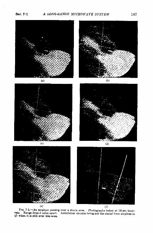
SEC. 71] A LONG-RANGE MICROWAVE SYSTEM 197
(a)
(c)
(e)FIG. 7.2.—An airplane passing over a storm area, Photographs taken at 15-sec inter-
vals. Range lines 2 miles apart. Anticlutter circuits bring out the signal from airplane inU) when it ia stilf over this area.
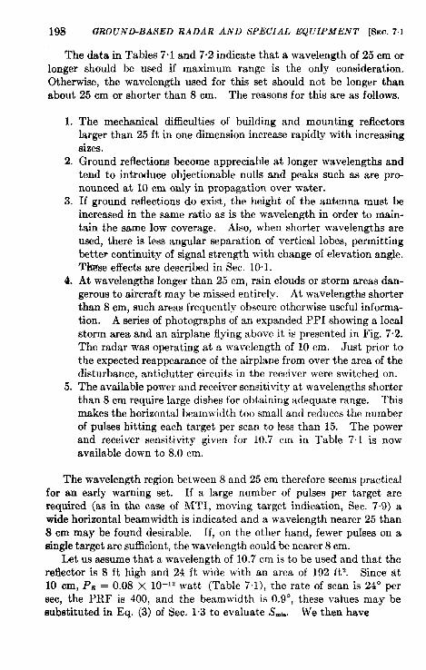
198 GROUND-BASED RADAR AND SPECIAL EQUIPMENT [SEC.71
The data in Tables 7.1 and 7.2 indicate that a wavelength of 25 cm orlonger should be used if maximum range is the only consideration.Otherwise, the wavelength used for this set should not be longer thanabout 25 cm or shorter than 8 cm. The reasons for this are as follows.
1.
2.
3.
4.
5.
The mechanical difficulties of building and mounting reflectorslarger than 25 ft in one dimension increase rapidly with increasingsizes.Ground reflections become appreciable at longer wavelengths andtend to introduce objectionable nulls and peaks such as are pro-nounced at 10 cm only in propagation over water.If ground reflections do exist, the height of the antenna must beincreased in the same ratio as is the wavelength in order to main-tain the same low coverage. Also, when shorter wavelengths areused, there is less angular separation of vertical lobes, permittingbetter continuity of signal strength with change of elevation angle.Thgse effects are described in Sec. 101.At wavelengths longer than 25 cm, rain clouds or storm areas dan-gerous to aircraft maybe missed entirely. At wavelengths shorterthan 8 cm, such areas frequently obscure otherwise useful informa-tion. A series of photographs of an expanded PPI showing a localstorm area and an airplane flying above it is presented in Fig. 7.2.The radar was operating at a wavelength of 10 cm. Just prior tothe expected reappearance of the airplane from over the area of thedisturbance, anticlutter circuits in the receiver were switched on.The available Dower and receiver sensitivity at wavelendhs shorterthan 8 cm require large dishes for obtaining adequate range. Thismakes the horizontal beamwidth too small and reduces the numberof pulses hitting each target per scan to less than 15. The powerand receiver sensitivity given for 10.7 cm in Table 7.1 is nowavailable down to 8.0 cm.
The wavelength region between 8 and 25 cm therefore seems practicalfor an early warning set. If a large number of pulses per target arerequired (as in the case of MTI, moving target indication, Sec. 7-9) awide horizontal beamwidth is indicated and a wavelength nearer 25 than8 cm may be found desirable, If, on the other hand, fewer pulses on asingle target are sufficient, the wavelength could be nearer 8 cm.
Let us assume that a wavelength of 10.7 cm is to be used and that thereflector is 8 ft high and 24 ft wide with an area of 192 ft2. Since at10 cm, P.Q = O.O8 X 10-’2 watt (Table 7.1), the rate of scan is 24” persee, the PRF is 400, and the beamwidth is 0.9°, these values may besubstituted in Eq. (3) of Sec. 1.3 to evaluate S~h. We then have
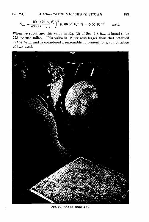
200 GROUND-BASED RADAR AND SPECIAL EQUIPMENT [8EC. 7,1
Although the range would be increased by lengthening the pulse, itis desirable to limit the pulse length to 1- or 2-psec duration. Longer
pulses would make it more difficult to resolve airplanes close to oneanother and shorter pulses might cause serious loss in range.
Radar information must be presented in such a way that the operatorshave a clear picture of all activities in a particular area. In the early
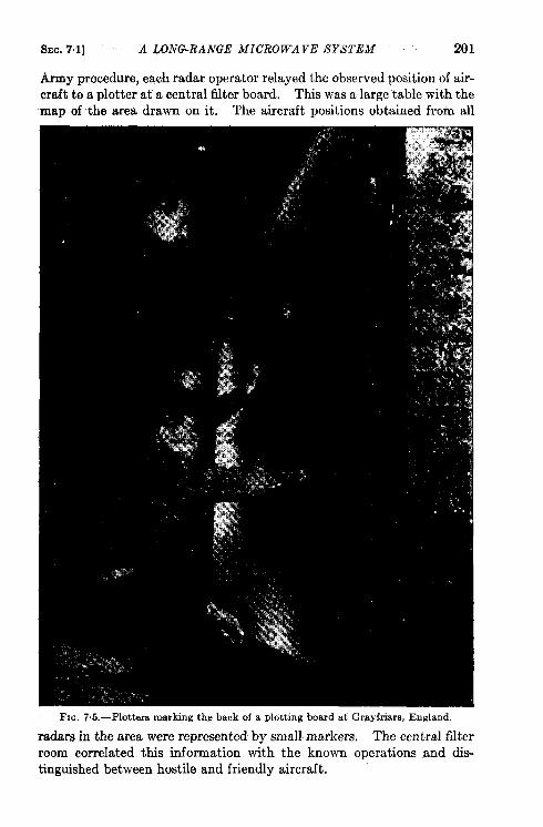
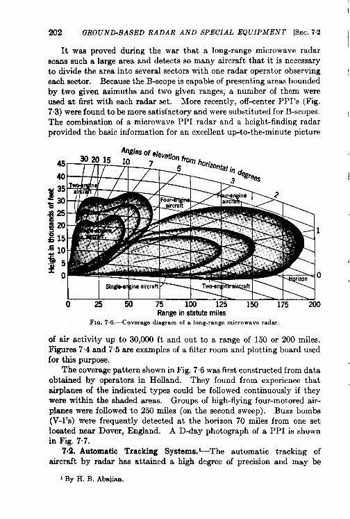
{
202 GROUND-BASED RADAR AND SPECIAL EQUIPMENT [SEC. 7.2 IIt was proved during the war that a long-range microwave radar
scans such a large area and detects so many aircraft that it is necessaryto divide the area into several sectors with one radar operator observingeach sector. Because the B-scope is capable of presenting areas boundedby two given azimuths and two given ranges, a number of them wereused at first with each radar set. More recently, off-center PPI’s (Fig.7.3) were found to be more satisfactory and were substituted for B-scopes.The combination of a microwave PPI radar and a height-finding radarprovided the basic information for an excellent up-to-the-minute picture
—11—
i
1
0
I I I I I 1% I \ I0 25 50 75 100 125 150 175 200
Rangein statute miles
FIG. 7.6.<overage diagram of a long-range microwave radar.
of air activity up to 30,000 ft and out to a range of 150 or 200 miles.Figures 74 and 7.5 are examples of a filter room and plotting board usedfor this purpose.
The coverage pattern shown in Fig. 7.6 was first constructed from dataobtained by operators in Holland. They found from experience thatairplanes of the indicated types could be followed continuously if theywere within the shaded areas. Groups of high-flying four-motored air-planes were followed to 250 miles (on the second sweep). Buzz bombs(V-l’s) were frequently detected at the horizon 70 miles from one setlooated near Dover, England. A D-day photograph of a PPI is shownin Fig. 7“7.
7,2. Automatic Tracking Systems._The automatic tracking ofaircraft by radar has attained a high degree of precision and may be
I By H. B. Abajian.
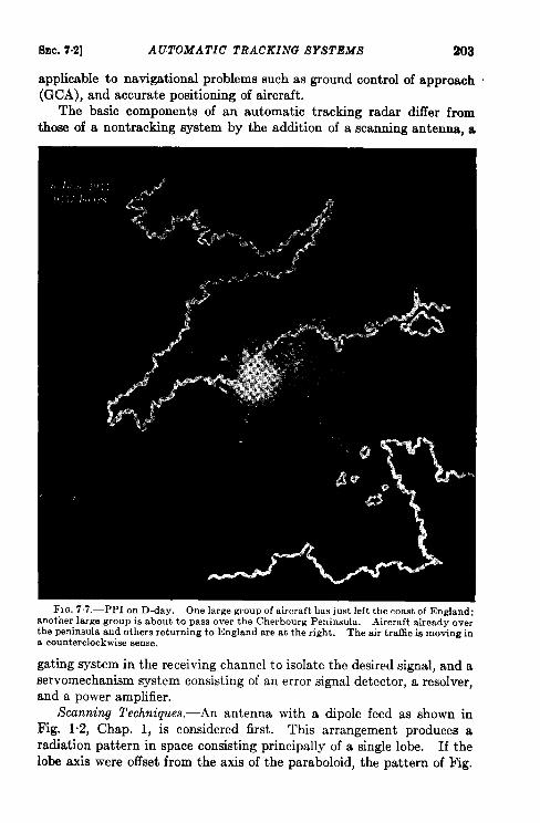
SEC. 7.2] AUTOMATIC TRACKING SYSTEMS 203
applicable to navigational problems such as ground control of approach .(GCA), and accurate positioning of aircraft.
The basic components of an automatic tracking radar differ fromthose of a nontracking system by the addition of a scanning antenna, a
FIG. 77.-PPI on D-day. One large group of aircraft has just left the coast of England;another large group is about to pass over the cherbourg peninsula. Aircraft already overthe peninsula and others returning to England are at the right. The air traffic is moving ina counterclockwise sense.
gating system in the receiving channel to isolate the desired signal, and aservomechanism system consisting of an error signal detector, a resolver,and a power amplifier.
Scanning Techniques.—An antenna with a dipole feed as shown inFig. 1.2, Chap. 1, is considered first. Thk arrangement produces aradiation pattern in space consisting principally of a single lobe. If thelobe axis were offset from the axis of the paraboloid, the pattern of Fig.
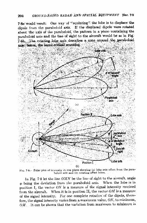
ml GROUND-BASED RADAR’ ~N& SPECf~L EQVIPMENT [SEC.7s2
. . . . . ...(b)
FIQ, 78.-Polar plot of intensity in one plane showing (a) lobe axis offset from the para-boloid axis and (b) rotating offset lobes.
In Fig. 7.8 let the line OMN be the line of sight to the aircraft, angle& being the deviation from the paraboloid axis. When the lobe is inposition I, the vector ON is a measure of the signal in~nsity receivedfrom the aircraft. When it is in position II, the vector OM is a measureof the signal intensity. For one complete rotation of the dipole, there-fore, the signal intensity varies from a maximum value, ON, to minimum,OM. It can be shown that the variation from maximum to minimum is
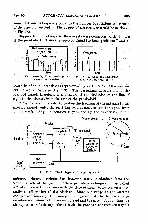
SEC. 7.2] A UT(XWA TIC TRACKING SYSTEMS 205
sinusoidal with a frequency equal to the number of Totatiom per seeondof the dipole drive shaft. The output of the receiver would be as shownin Fig. 7,9a.
Suppose the line of sight to tiie riirmaft were coincident with the axisof the paraboloid. Then the received signal for both pbsitions I and II
ss~
,..k.;~
Time TmeFIG. 7.9.—(a) Video ,nodulation FIrJ.7.9.—(b) Constant-amnlitude
when an error exists. video when no error exists.
would be of equal intensity as represented by vector OP and the receiveroutput would be as in Fig. 7.9b. The percentage modulation of thereceived signal, therefore, is a measure of the deviation of the line ofsight to the aircraft from the axis of the paraboloid.
Gated Receiver.—In order to confine the tracking of the antenna to theselected aircraft only, the receiving system must isolate the signal fromthat aircraft. Angular isolation is provided by the directivity of the
Receiver
‘n’”’~=system forautomatic
i’_ tracking
Gate
Gate- generatortiming
Gate
adjustment
FIG. 7 10.—Block diagram of the gating system.
antenna. Range disc~imination, however, must be obtained from thetiming circuits of the system. These provide a rectangular pulse, calleda “gate,” coincident in time with the desired signal to switch on a nor-mally cutoff section of the receiver. Since the range to the aircraftchanges continuously, the timing of the gate must also be variable tomaintain coincidence of the aircraft signal and the gate. A simultaneousdisplay on a cathode-ray tube of both the gate and the received signals
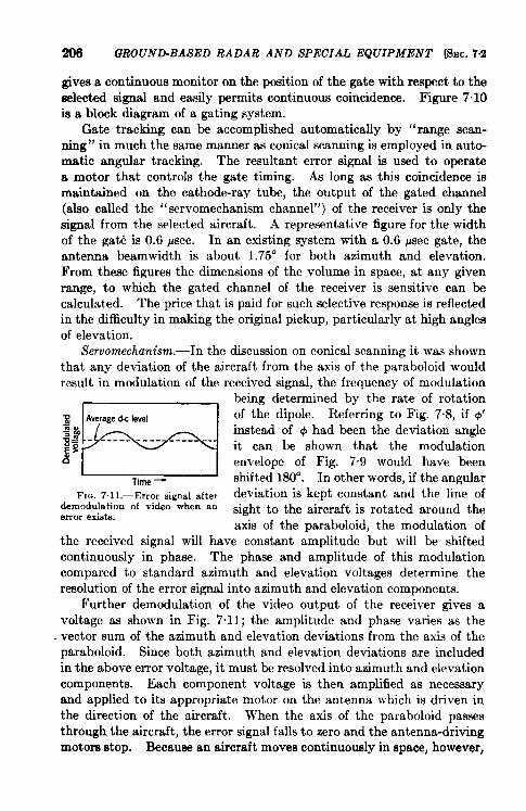
!206 GROUND-BASED RADAR AND SPECIAL EQUIPMENT ~SEC. 72
gives a continuous monitor on the position of the gate with respect to theselected signal and easily permits continuous coincidence. Figure 7”10is a block diagram of a gating system.
Gate tracking can he accomplished automatically by “range scan-ning” in much the same manner as conical scanning is employed in automatic angular tracking. The resultant error signal is used to operatea motor that controls the gate timing. As long as this coincidence ismaintained on the cathode-ray tube, the output of the gated channel(also called the “servomechanism channel”) of the receiver is only thesignal from the selected aircraft. A representative figure for the widthof the gate is 0.6 Wee. In an existing system with a 0.6 ysec gate, theantenna beamwidth is about 1.75° for both azimuth and elevation.From these figures the dimensions of the volume in space, at any givenrange, to which the gated channel of the receiver is sensitive can becalculated. The price that is paid for such selective response is reflectedin the difficulty in makhg the original pickup, particularly at high anglesof elevation.
Servomechanism.—In the discussion on conical scanning it was shownthat any deviation of the aircraft from the axis of the paraboloid wouldresult in modulation of the received signal, the frequency of modulation
being determined by the rate of rotation
~
B
Averaged< level of the dipole. Referring to Fig. 7.8, if 1#1’:% / instead of @ had been the deviation angle~; - ------ ------- --
it can be shown that the modulation13 envelope of Fig. 79 would have been
Time_ sh~fted 180°. In other words, if the angularFIG.7.11.—Error signal after deviation is kept constant and the line of
demodulation of video when anerror exists.
sight to the aircraft is rotated around theaxis of the paraboloid, the modulation of
the received signal will have constant amplitude but will be shiftedcontinuously in phase. The phase and amplitude of this modulationcompared to standard azimuth and elevation voltages determine theresolution of the error signal into azimuth and elevation components.
Further demodulation of the video output of the receiver gives avoltage as shown in Fig. 7.11; the amplitude and phase varies as thevector sum of the azimuth and elevation deviations from the axis of theparaboloid. Since both azimuth and elevation deviations are includedin the above error voltage, it must be resolved into azimuth and elevationcomponents. Each component voltage is then amplified as necessaryand applied to its appropriate motor on the antenna which is driven inthe direction of the aircraft. When the axis of the paraboloid passesthrough the aircraft, the error signal falls to zero and the antenna-drivingmotors stop. Because an aircraft moves continuously in space, however,
&c. 7.3] HEIGHT-FINDING METHODS 207
the antenna must move continuously to keep azimuth and elevationdeviation as near zero aa possible.
Data Transmission.-There remains only the question of transmissionof the data to the communication center. Single and multispeed syn-chros geared to the antenna provide precise angular data; single andmultispeed syncbroe geared to the controls which position the ranginghairline as well as the range gate provide precise slant-range data. Ifdesired, potentiometers can be substituted for the synchros, or both canbe used simultaneously.
Auzilia~ Equipment.-In order to make full use of the informationavailable at the system described, the following auxiliary equipmentwould be desirable.
1. Suitable PPI’s for initial search or to aid in providing hominginformation.
2. Range, azimuth, elevation, and altitude synchros grouped andphotographed by a constant-speed camera to make a permanentrecord of the co~rse of the aircraft. The disadvantage of such asystem is that considerable computation is necessary in order toreconstruct the course and to determine rates.
3. An altitude converter, solving the equation H = D sin E, whereH = altitude, D = slant range, and E = elevation angle, to gi~ethe true altitude of an aircraft above the radar position.
4. An automatic plotting board to trace the ground course accuratelyon a map. In addition to the ground plot, the plotting board canbe made to include the following aids: (a) timing markers to permiteasy calculation of rates at any point at any future time; (b) ratemeters so that rates can be read instantaneously; (c) a ground-bearing meter to indicate the bearing of the ground course. Driftcan then be determined easily from this indicated bearing and thecompass bearing in the aircraft.
5. A computer to give flying time, course, and glide angle for bringingan aircraft to the airport.
6. A parallel receiving system, tuned to a beacon transponder in theaircraft, to receive only coded beacon responses.
HEIGHT FINDERS
BY H. P. STABLER
7.3. Height-fiding Methods. Introduction.—Radar height findersare devices for measuring the slant range of an airplane and the elevationangle of the radiation path between the airplane and station. Of thesetwo factors, the angular measurement is peculiar to height-findingwhereas the measurement of slant range presents no unusual problem.
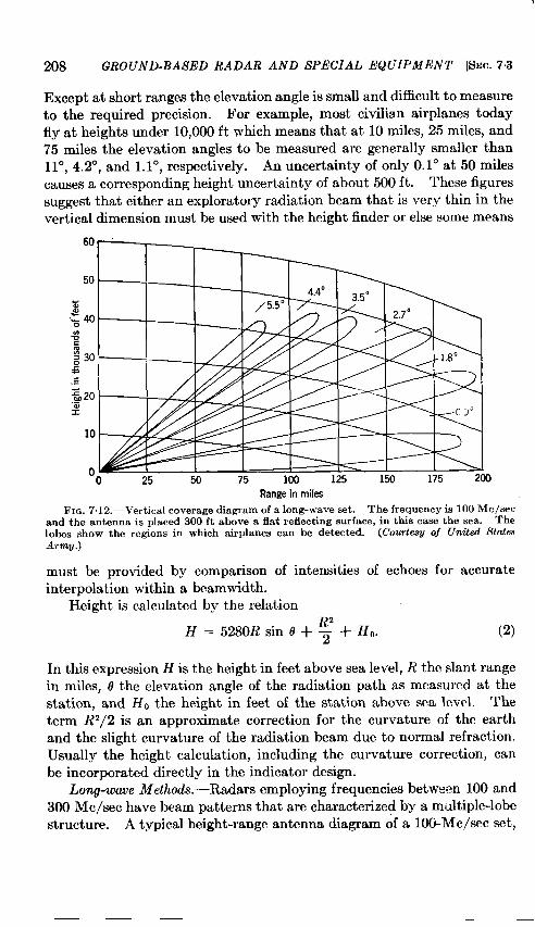
208 GROUND-BASED RADAR AND SPECIAL EQUIPMENT [SEC. 7.3
Except at short ranges the elevation angle is small and difficult to measureto the required precision. For example, most civilian airplanes today
fly at heights under 10,000 ft which means that at 10 miles, 25 miles, and75 miles the elevation angles to be measured are generally smaller than11°, 4.2°, and 1.1°, respectively. An uncertainty of only 0.1° at 50 miles
causes a corresponding height uncertain y of about 500 ft. These figuressuggest that either an exploratory radiation beam that is very thin in thevertical dimension must be used with the height finder or else some means
Range in miles
FIG. 7.12.—Vertical coverage diagram of a long-wave set. The frequency is 100 Me/seeand the antenna is placed 300 ft shove a flat reflecting surface, in this case the sea. Thelobes show the regions in which airplanes can bc. detected. (CourteSV of United flt~mArm~.)
must be provided by comparison of intensities of echoes for accurateinterpolation within a beamwidth.
Height is calculated by the relation—
H = 5280R sin O + ~ + Ho. (2)
In this expression H is the height in feet above sea level, R the slant range
in miles, o the elevation angle of the radiation path as measured at thestation, and HO the height in feet of the station above sea level. Theterm R2/2 is an approximate correction for the curvature of the earthand the slight curvature of the radiation beam due to normal refraction.
Usually the height calculation, including the curvature correction, canbe incorporated directly in the indicator design.
Long-wave il!lethods.-Radars employing frequencies between 100 and300 Me/see have beam patterns that are characterized by a multiple-lobestructure. A typical height-range antenna diagram of a 100-Mc/sec set,
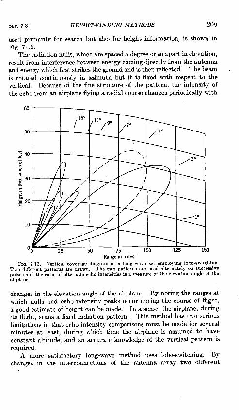
SEC. 7.3] HEIGHT-FIifDING METHODS 209
used primarily for search but also for height information, is shown inFig. 7.12.
The radiation nulls, which are spaced a degree or so apart in elevation,result from interference between energy coming djrectly from the antennaand energy which first strikes the ground and is then reflected. The beamis rotated continuously in azimuth but it is fixed with respect to the
vertical. Because of the fine structure of the pattern, the intensity of
the echo from an airplane flying a radial course changes periodically with
,// I / Y
25 ‘o
Range inmilesFIG. 7. 13.—Vertical coverage diagram of a long-wave set employing lobe-switching.
Two different patterns are drawn. The two patterns are used alternately on successivepulses and the ratio of alternate echo intensities is a measure of the elevation angle of theairplane.
changes in the elevation angle of the airplane. By noting the ranges at
which nulls and echo intensity peaks occur during the course of flight,
a good estimate of height can be made. In a sense, the airplane, during
its flight, scans a fixed radiation pattern. This method has two serious
limitations in that echo intensity comparisons must be made for several
minutes at least, during which time the airplane is assumed to have
constant altitude, and an accurate knowledge of the vertical pattern is
required.
A more satisfactory long-wave method uses lobe-switching. By
changes in the interconnections of the antenna array two different
210 (?ROUND-BASED RADAR AND SPECIAL EQUIPMENT [SEC. 7.3
vertical lobe patterns are possible. These may be as shown in Fig. 7-13,pattern A in solid lines and pattern B in d~tted lines.
Automatic switching occurs in such a way that the two patterns areused alternately on successive pukes. The echo intensity for pattern Ais compared with that for B, and their ratio is a measure of the elevationangle of the airplane. Additional patterns are avauable to resolveambi~ities and to give better high-angle coverage of the whole field.The echo-intensity ratio is estimated from an A-scope dkplay (withoutinterrupting the azimuth sweep of the antenna) and height is read from acarefully prepared calibration chart. Under favorable circumstances,good readings require two or three sweeps of the antenna, a time intervalof perhaps a minute.
Satisfactory lobe patterns can be obtained only by very careful selec-tion of the site. For example, the ground should be a good conductor,and level to within a few feet in all directions from the antenna for adistance of ~ mile. Calibration patterns are likely to be dependent onazimuth since the ground characteristics as far away as 1 mile have someeffect on pattern intensity. Because of this dependence on site andbecause of poor resolution and low-angle coverage, long-wave heightfinders are decidedly inferior to the more recent microwave systems.
“Pencil Beam” uith Conical Scan.-If a microwave pencil beam ispointed directly at an airplane, the elevation angle required for a heightreading is determined by measuring the tilt angle of the antenna. Thesharper the beam, the more accurately can its center be recognized andthe smaller will be the uncertainty in the angular measurement. Thesharp beam gives the required angular precision, however, at the expenseof making the target difficult to find.
Precision of setting with a broad pencil beam is achieved by a conicalscan as described in Sec. 7.2. This method also depends on a comparisonof echo intensities within a beamwidth. Unless the target lies directlyon the axis of the radiation cone, the signal is amplitude-modulated at thescan ffequency. The modulation is indicated by an error detectionmeter and the ant enna orientation is adjusted until the meter shows zeromodulation. Range-gating is required and the height is computedelectrically and read on a meter. A conical scan system is well-suited totracking individual targets but the searchlighting procedure is slow whenthe heights of several airplanes must be found rapidly.
Vertically Scanned Beams.-Height systems employing a verticalscan are frequently called “ beavertails” because of their flapping motionand the shape of their beams. The beams are thinner in elevation thanin azimuth, a typical cross section being 1° by 4°. The beam sweeps upand down continuously across a target and the echo is observed on arange-height indicator, RHI, which shows height and range as rectangular
SEC. 7.3] HEIGHT-FINDING METHODS 211
coordinates. The echo extends over perhaps a 1° elevation angle, andheight readings are made directly by interpolating to the center of thecorresponding pip on the face of the scope.
Beavertails fall into two categories according to whether their azimuthmotion is discontinuous or continuous. The discont~uous type issearchlighted in azimuth and is always operated in connection with anassociated search set which furnishes azimuth and range information.The azimuth data is used to orient the height-finder mount. correctly(by means of a servo); the range then identifies the airplane in questionon the indicator.
The continuous type of beavertail rotates in azimuth as it sweepsrapidly in elevation, the rate of advance in azimuth being such as to leaveno gaps in the coverage of the whole field. Azimuth and range informa-tion from an associated search set are used to select the appropriatesector for presentation on the RHI, although this is not necessary for itsoperation. A continuous beavertail scanner can furnish data to manyRHI’s operating independently of each other. If the time for onecomplete azimuth circuit can be made sufficiently short, this typeof system is well-suited for handling a large number of control problemssimultaneously.
V-bsam.-With this method the functions of plan position search andheight-finding are combined into a single system. TWO radiationsheets are employed. These are thin in the azimuth direction and suffi-ciently broad in elevation to give the desired vertical coverage. Onesheet is vertical; the other is tilted at an angle of 45° to the vertical. Theantennas for the two sheets are mounted on a single platform that rotatescontinuously in azimuth. The direction of rotation is such that thevertical sheet always leads the slant sheet. In each revolution a targetis intercepted, first by the vertical beam, and then by the slant beam.The angle through which the mount turns between the two interceptionsis a measure of the elevation angle of the target. It is clear that themotion of the slant sheet in azimuth also results in a simultaneoussweep in elevation. Angles of elevation are thus turned into apparentazimuth delay angles. The vertical beam alone is used for planposition information.
If the antennas for the vertical and slant sheets are oriented on themount so that the two sheets intersect in a horizontal plane, the twobeams form the edges of a large tipped “V” or trough, the leading edgebeing vertical and the trailing edge at 45° with respect to it. In thiscase the sine of the azimuth-delay angle is equal to the tangent of theelevation angle, and the two angles are very nearly equal. A difficultywith this arrangement is that the finite azimuth thickness of the beamscauses them to overlap near the horizon with the result that the slant
212 GROUND-BASED RADAR AND SPECIAL EQUIPMENT [i+JC. 74
and vertical echoes from a low elevation angle target are not resolved.This difficulty is avoided by offsetting the slant antenna by a fixed lag
angle 10° in azimuth behind the vertical. The ground edges of the twobeams are then separated by 10° and all delay angles increased by thisamount. This design also makes it possible to divide the height-indi-cator screen into two regions, one restricted to vertical signals andthe other to slant signals. The fixed delay must be kept small sinceit increases the percentage accuracy requirements of the angularmeasurement.
The height indicator is a modified B-scope with range plotted hori-zontally and azimuth vertically. The lower portion of the indicator
screen receives vertical beam signals over a particular 10° azimuth sectorchosen by the height operator. The remaining upper portion of thepresentation receives echoes from the slant beam. Each echo in the lowerportion has a companion slant echo in the upper portion at the samerange. A movable external scale is used to measure the-azimuth separa-tion of the echoes and gives readings directly in height. Many heightindicators can be operated independently of each other from the samesystem and, like the continuous beavertail, the V-beam method is par-ticularly suited to handling many control problems simultaneously.
7.4. General Problems of Design. Absolute and Relative Height
Accuracy.—It is desirable to distinguish between the accuracy of themeasurements of difference of the height between two airplanes and theaccuracy of the absolute value of the height obtainable for a single air-plane. If the two airplanes are widely separated in bearing, range, andheight, the accuracy in the difference in height may be little better thanthe absolute accuracy. As the separation of the two airplanes decreases,
the accuracy of the difference tends to improve. A specification of rela-tive height accuracy implies that the two airplanes are within a fewthousand feet of each other in height and sufficiently close in azimuthand range to be seen simultaneously with the same indicator setting.
Accurate readings of absolute height require correct adjustment ofthe expansions of the indicator sweep and careful determination of thezero altitude position whereas height differences are not so dependent oncalibration. For example, if the vertical axis of a beavertail mount is
actually not quite vertical, all elevation angles may appear to be toolarge at one azimuth and too small in the opposite azimuth by perhaps0.5°. This error does not affect relative height measurements for air-planes at the same azimuth. Or again, if the indicator expansions on anRHI are incorrect by 10 per cent, measurements on two airplanes at10)000 ft and 12,000 ft, respectively, will have absolute height errors ofabout 1000 ft but a relative height error of 200 ft.
In regions of anomalous propagation the measured absolute heights
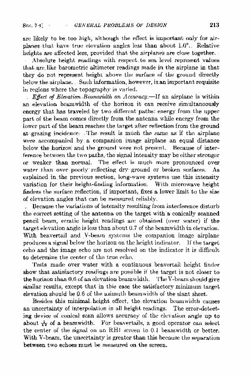
SEC. 74] GENERAL PROBLEMS OF DESIGN 213
are likely to be too high, although the effect is important only for air-planes that have true elevation angles less than about 1.OO. Relativeheights are affected less, provided that the airplanes are close together.
Absolute height readings with respect to sea level represent valuesthat are like barometric altimeter readings made in the airplane in thatthey do not represent height above the surface of the ground directlybelow the airplane. Such information, however, is an important requisitein regions where the topography is varied.
E#ect oj Elevation Beamwidth on Accuracy.-If an airplane is withinan elevation beamwidth of the horizon it can receive simultaneouslyenergy that has traveled by two different paths: energy from the upperpart of the beam comes directly from the antenna while energy from thelower part of the beam reaches the target after reflection from the groundat grazing incidence. The result is much the same as if the airplane
were accompanied by a companion image airplane an equal distance
below the horizon and the ground were not present. Because of inter-
ference between the two paths, the signal intensity may be either stronger
or weaker than normal. The effect is much more pronounced overwater than over poorly reflecting dry ground or broken surfaces. As
explained in the Prwious section, long-wave systems use this intensityvariation for their height-finding information. With microwave height
fiders the surface reflection, if important, fixes a lower limit to the size
of elevation angles that can be measured reliably.
Because the variations of intensity resulting from interference disturbthe correct setting of the antenna cm the target with w conically scanned
pencil beam, erratic height readings are obtained (over water) if the
target elevation angle is less than about 0.7 of the beamwidth in elevation.
With beavertail and V-beam systems the companion image airplane
produces a signal below the horizon on the height indicator. If the target
echo and the image echo are not resolved on the indicator it is difficult
to determine the center of the true echo.Tests made over water with a continuous beavertail height finder
show that satisfactcmy readings are possible if the target is not closer to
the horizon than 0.6 of an elevation beamwidth. The V-beam should give
similar results, exce@ that in this case the satisfactory minimum target
e~evation should be 0.6 of the azimuth beamwidth of the slant sheet.
Besides this minimal height effect, the elevation beamwidth causes
an uncertainty of interpolation in all height readings. The error-detect-
ircg device of conical scan allows accuracy of the elevation angle up toabout ~ of a be-width. For beavertails, a good operator can select
the center of the signal on an RH1 screen to 0.1 beamwidth or better.
With V-beam, the uncertainty is greater than this because the separation
between two echoes must be measured on the screen.
214 GROUND-BASED RADAR AND SPECIAL EQUIPMENT @EC. 7.4
While the beamwidth spoken of here refers to the tw~way half-powerwidth which is a function ordy of the wavelength and antenna size, theactual echo length of the spot on the screen of an indicator depends alsoon the signal intensity, that is, on the range and size of the target. Fre-quently, the best height readings are obtained when the signal isrelatively weak and the echo correspondingly small. It is impor-tant that the antenna be designed to reduce elevation side lobes to aminimum.
Pulse Spw”ng Effect.-Target information is not obtained continu-ously, but at the puke repetition frequency, PRF; a beam which isscanning may move appreciably between pulses and produce a corres-ponding uncertainty in the measured data. For instance, suppose that abeavertail beam requires the time of an integral number of pulses tosweep across a target. As the beam sweeps upward, a pulse may occureither just before or at the moment that the upper edge of the beamreaches the target. The difference in height reading between these twopossibilities is the vertical distance (at the target range) that the beammoves between pulses. A fair measure of the uncertainty in elevationangle due to this effect is one-half the angular displacement of the beambetween pulses for continuous beavertail systems and, on a probabilitybasis, somewhat less than twice this amount for V-beam systems. Theuncertainty with discontinuous beavertails can be reduced by multiplevertical scans.
Scanning Losses and Speeds. -To compare the effect of scanning onthe range capabilities of different beavertail and V-beam systems, it isconvenient to write the scanning-loss ratio discussed in Sec. 1.3 in thefollowing form:
Scan loss factor =( )
solid angle over which energy is spread in 8 sec ;~beam cross section
This represents the loss on a power basis, while the factor by which rangeis reduced is obtained by changing the exponent from } to ~. Both thesolid angle of scan and the cross section of the beam are to be measured inthe same units, square degrees, for example, and their ratio indicates howthinly the energy pulses are spaced. In calculating the ratio for dis-continuous beavertails, the azimuth beamwidth appears as a factor inboth numerator and denominator, thus canceling out; and similarly,the vertical beam width cancels from the ratio for a V-beam. Clearlythe scanning loss becomes a particularly important consideration in thedesign of continuous beavertails, since the numerator involves motionin both azimuth and elevation.
The traffic capacity of discontinuous beavertails is limited by operatortime (for azimuth servo adjustment and height reading), azimuth slewing
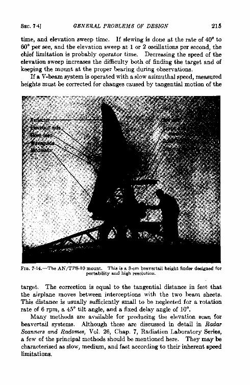
SEC. 74] GENERAL PROBLEMS OF DESIGN 21s
time, and elevation sweep time. If dewing is done at the rate of 40° to
60° per see, and the elevation sweep at 1 or 2 oscillations per second, thechief limitation is probably operator time. Decreasing the speed of theelevation sweep increases the difficulty both of finding the target and ofkeeping the mount at the proper bearing during observations,
If a V-beam system is operated with a slow azimuthal speed, measuredheights must be corrected for changes caused by tangential motion of the
Fm. 7.14.—The AN/TPS-10 mount. Thie is a 3-em beavertail height finder designed forportability and high resolution.
target. The correction is equal to the tangential distance in feet thatthe airplane moves between interceptions with the two beam sheets.This distance is usually sufficiently small to be neglected for a rotationrate of 6 rpm, a 45° tilt angle, and a fixed delay angle of 10°.
Many methods are available for producing the elevation scan forbeavertail systems. Although these are discussed in detail in Radar
Scanners and Radom.es, Vol. 26, Chap. 7, Radiation Laboratory Series,a few of the principal methods should be mentioned here. They maybecharacterized as slow, medium, and fast according to their inherent speedlimitations.
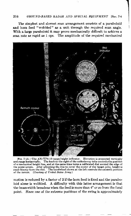
216 GROUND-BASED RADAR A.VD SPECIAL EQUIPMENT [SEC. 7.4
The simplest and slowest scan arrangement consists of a paraboloid
and horn feed “wobbled” as a unit through the required scan angle.With a large paraboloid it may prove mechanically difficult to achieve ascan rate as rapid as 1 cps. The amplitude of the required mechanical
FIG. 7. 15.—The AN/TPS-10 range-height indicator. Elevation is presented verticallyand renge horizontally. The knob to the right of the cathode-ray tube controls the positionof a mechanical height line, and at the same time turns a calibrated dial around the edge ofthe scope screen. After adjusting the line to cover the center of the target echo, height isread directly from the dial. The handwheel shown at the left controls the azimuth positionof the mount. (Courtes~ of United State-s ArmU.)
motion is reduced by a factor of 2 if the horn feed is fixed and the parabo-loid alone is wobbled. A di5culty with thk latter arrangement is thatthe beamwidth broadens when the feed is more than 4° or so from the focal
point. Since one of the extreme positions of the swing is approximately
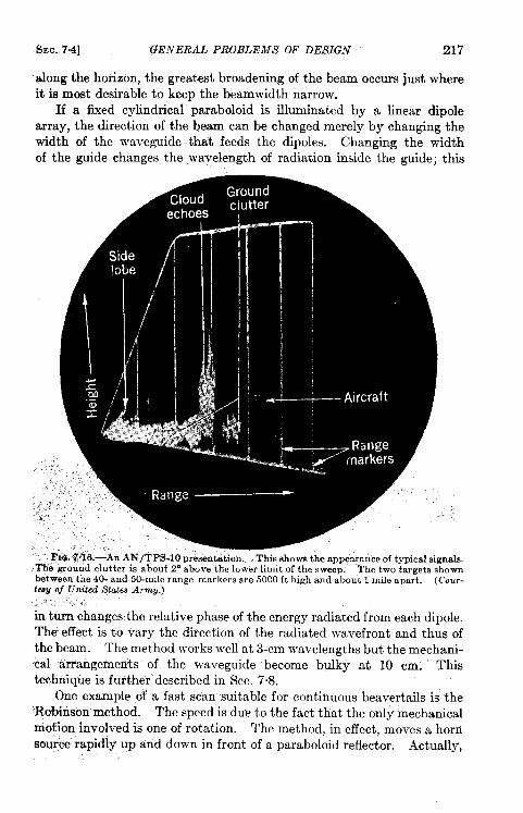
SEC. 74] GENERAL PROBLEMS OF DESIGN 217
along the horizon, the greatest broadening of the beam occurs just whereit is most desirable to keep the beamwidth narrow.
If a fixed cylindrical paraboloid is illuminated by a linear dipolearray, the direction of the beam can be changed merely by changing thewidth of the waveguide that feeds the dipoles. Changing the widthof the guide changes the wavelength of radiation inside the guide; this
On~ example of a fast scan suitable for continuous beavertails is the‘I@binson method. The speed is due to the fact that the only mechanicalmotion involved is one of rotation. The method, in effect, moves a hornsource rapidly up and down in front of a paraboloid reflector. Actually,
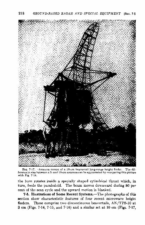
218 GROUND-BASED RADAR AND SPECIAL EQUIPMENT [SEC.7.5
FIG. 7.17.—Antenna mount of a 10-cm beavertail long-range height finder. The dif-ference in size between a 3- and 10-cm antenna can be appreciated by comparing this picturewith Fig. 7.14.
the horn rotates inside a specially shaped cylindrical throat which, inturn, feeds the paraboloid. The beam moves downward during 80 percent of the scan cycle and the upward motion is blanked,
7s5. Illustrations of Some Recent Systems.—The photographs of thissection show characteristic features of four recent microwave heightfinders. These comprise two discontinuous beavertails, AN/TPS-10 at3 cm (Figs. 7“14, 7“15, and 7“16) and a similar set at 10 cm (Figs. 7.17,
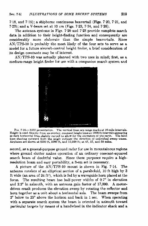
SEC. 7.5] ILL USTRA TIOiVS OF SOIUE RECENT SYSTEMS 219
7.18, and 7.19); a shipborne continuous beavertail (Figs. 7.20, 7.21, and7.22); and a V-beam set at 10 cm (Figs. 7“23, 7“24, and 7“25).
The antenna systems in Figs. 7.20 and 7.23 provide complete searchdata in addition to their height-finding function and consequently areconsiderably more elaborate than the simple beavertails. SinceAN/TPS-10 is probably the most likely of the four sets to serve as amodel for a future aircraft-control height finder, a brief consideration ofits design constants may be of interest.
AN/TPS-10 was actually planned with two uses in mind; first, as amedium-range height finder for use with a companion search system and
FIG. 7.18.—RHI presentation. The vertical lines are range marks at lo-mile intervals.Height is read directly from an overlay, constant height lines at 1000-ft intervals appearingas dark horizontal lines slightly curved to allow for the curvature of the eurth. The faintlines slanting outward from the origin indicate the direction of individual swsep traoes.Airplanes are showu at 6500 ft, 5200 ft, and 10,500 ft; at 47, 57, and 69 miles.
second, as a general-purpose ground radar for use in mountainous regionswhere ground clutter makes operation of an ordinary cosecant-squaredsearch beam of doubtful value. Since these purposes require a high-resolution beam and easy portability, a 3-cm set is necessary.
A picture of the AN/TPS-10 mount is shown in Fig. 7.14. Theantenna consists of an elliptical section of a paraboloid, 10 ft high by 3ft wide (an area of 24 ft’), which is fed by a waveguide horn placed at thefocus. The resulting beam has half-power widths of 0.7° in elevationand 2.2° in azimuth, with an antenna gain factor of 17,000. A motor-driven crank produces the elevation sweep by rotating the reflector andhorn together as a unit about a horizontal axis. The beam sweeps from2° below to 23” above the horizon and back in 1 sec. When operatingwith a separate search system the beam is oriented in azimuth towardparticular” targets by means of a handwheel in the indicator shack and a
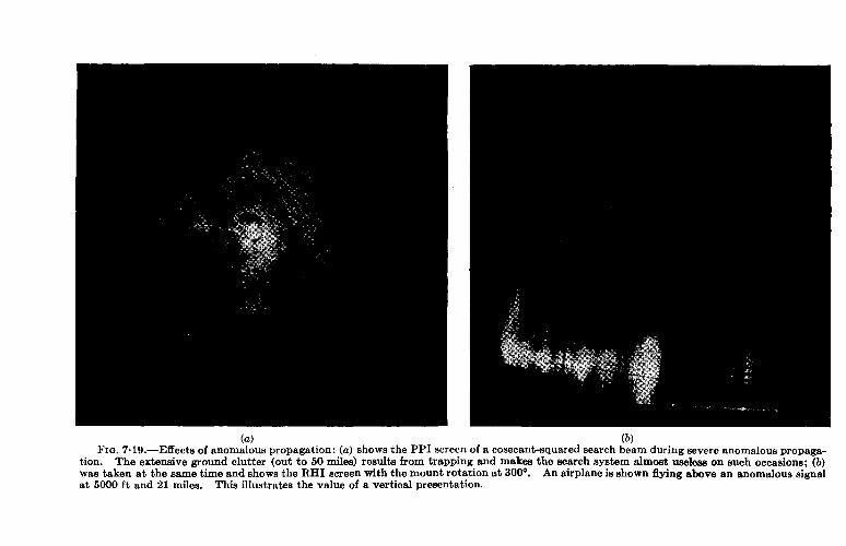
(a) (b)FIG. 7.19.—Effects of anomalous propagation: (a) shows the PP1 screenof a cosecant-squarecfsearchbeam duringsevereanomalouspropaga-
tion. The extensiveground clutter (out to 50 miles) results from trapping and makesthe searchsystem almost uselesson such occasions; (b)was taken at the sametime and showsthe RHI screenwith the mount rotation at 300°. An airplaneis shown flying above an anomaloussignalat 6000 ft and 21 miles. This ilhwtrates the value of a vertical presentation.
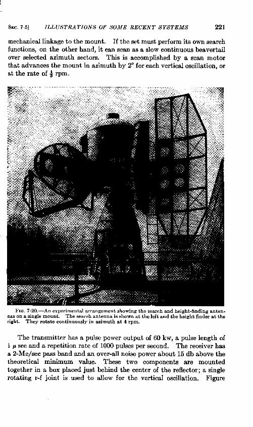
SEC. 7.5] ILL USTRA TIONS OF
mechanical linkage to the mount.
SOME RECENT SYSTEMS 221
If the set must perform its own searchfunctions, on the- other hand, it can scan as a slow continuous heavertail
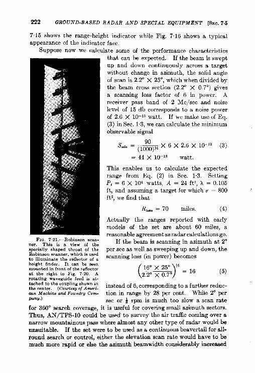
222 GROUND-BASED RADAR AND SPECIAL EQUIPMENT [SEC. 7.5
7.15 shows the range-height indicator while Fig. 7.16 shows a typicalappearance of the indicator face.
Suppose now we calculate some of the performance characteristics
FIG. 7.21.—Roblnaon scan-ner. This is a view of thespecially shaped throat of theRobinson scanner, which is usedto illuminate the reflector of aheight finder. It can be seenmounted in front of the reflectorat the right in Fig. 7.20. Arotating waveguide feed is at-tached to the coupling shown inthe center. (Courtesyof AmeTi-IXn Machine and Foundr# Com-pany.)
that can be expected. If the beam is sweptup and down continuously across a targetwithout change in azimuth, the solid angleof scan is 2.2° X 25°, which when divided bythe beam cross section (2.2’ X 0.7°) givesa scanning loss factor of 6 in power. Areceiver pass band of 2 Me/see and noiselevel of 15 db corresponds to a noise powerof 2.6 X 10⁻¹³ watt. If we make use of Eq.(3) in Sec. 1.3, we can calculate the minimumobservable signal
Sdn =90
— X 6 X 2.6 X 10-’3 (3)(looo)~+
= 44 x 10-13 watt.
This enables us to calculate the expectedrange from Eq. (2) in Sec. 1.3. SettingP, = 6 X 10’ watts, A = 24 ft’, k = 0.105ft, and assuming a target for which u = 800ft’, we find that
R-. = 70 miles. (4)
Actually the ranges reported with earlymodels of the set are about 60 miles, areasonable agreement as radar calculations go.
If the beam is scanning in azimuth at 2°per sec as well as sweeping up and down, thescanning loss (in power) becomes
LR%T=16 ‘5)instead of 6, corresponding to a further reduc-tion in range by 28 per cent. While 2° persec or + rpm is much too slow a scan rate
for 360° search coverage, it is useful for covering small azimuth sectors.Thus, AN/TPS-10 could be used to survey the air traffic coming over anarrow mountainous pass where almost any other type of radar would beunsuitable. If the set were to be used as a continuous beavertail for all-round search or control, either the elevation scan rate would have to bemuch more rapid or else the azimuth beamwidth considerably increased
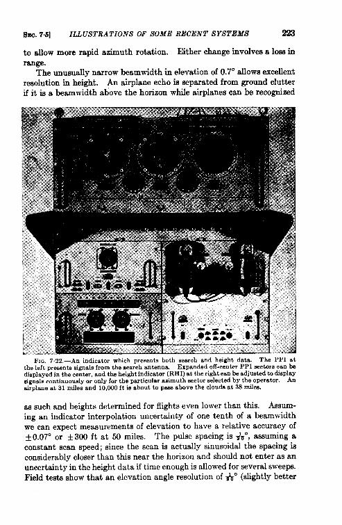
Sl!.e. 7.5] ILLUSTRATIONS OF SOME RECENT SYSTEMS 223
to allow more rapid azimuth rotation. Either change involves a 10M inrange.
The unusually narrow beamwidth in elevation of 0.7° allows excellentresolution in height. An airplane echo is separated from ground clutterif it is a beamwidth above the horizon while airplanes can be recognized
as such and heights determined for flights even lower than this. Assum-ing an. indicator interpolation uncertain y of one tenth of a beamwidthwe can expect measurements of elevation to have a relative accuracy of+0.070 or +300 ft at 50 miles. The pulse spacing is #u”, assuming aconstant scan speed; since the scan is actually sinusoidal the spacing isconsiderably closer than this near the horizon and should not enter as anuncertainty in the height data if time enough is allowed for several sweeps.Field tests show that an elevation angle resolution of # (slightly better
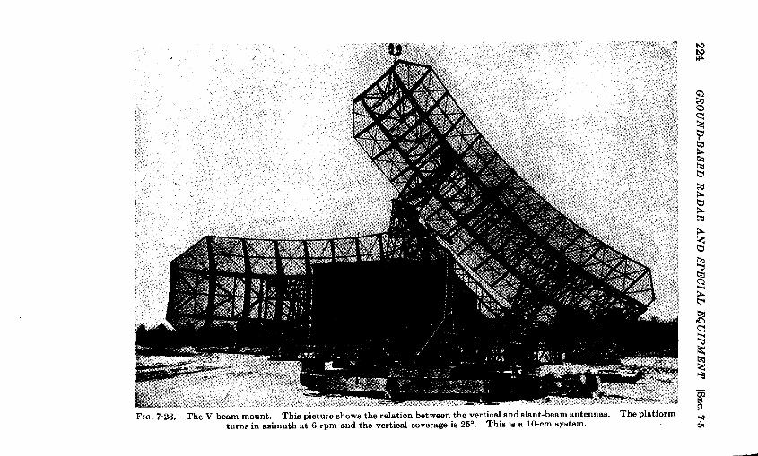
\
224G
RO
UN
D-B
ASE
DR
AD
AR
AN
DSP
EC
IAL
EQ
UIP
ME
NT
[SE
C.
75
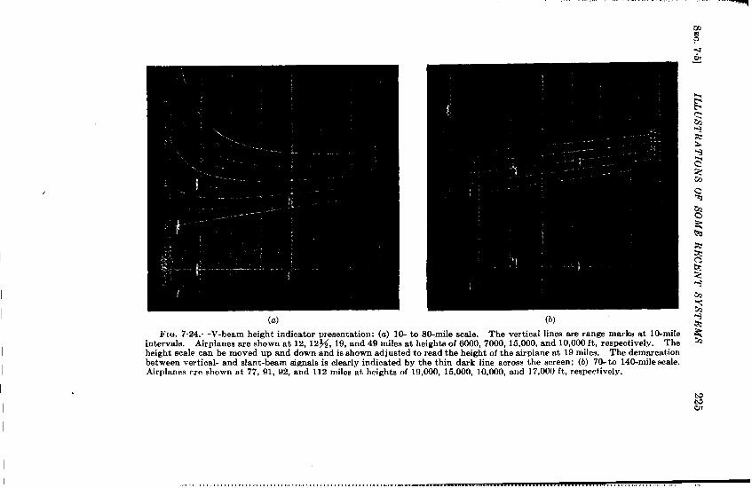
.. .---,—-,—.— .—.
.
(a) (b)
FIG. 7.24.—V-beam height indicator presentation: (a) 10- to 80-rnile scale. The vertical lines are range marks at lo-mileintervals. Airplanes are shown at 12, 12%, 19, and 49 miles at heights of 6000, 7000, 15,000, and 10,000 ft, respectively. Theheight scale can be moved up and down and is shown adjusted to read the height of the airplane at 19 miles. The demarcationbet ween vertical- and slant-beam signals is clearly indicated by the thin dark line across the screen; (b) 70-to 140-rrde scale.Airplanes m-e shown at 77, 91, 92, and 112 miles at beigbts of 19,000, 15,000, 10,000, and 17,000 ft. respectively.
. . ... .. ... .. . . .. .. .... . .. ..... . .. .... .. ..”...... .,, ,, .,,,, ,“
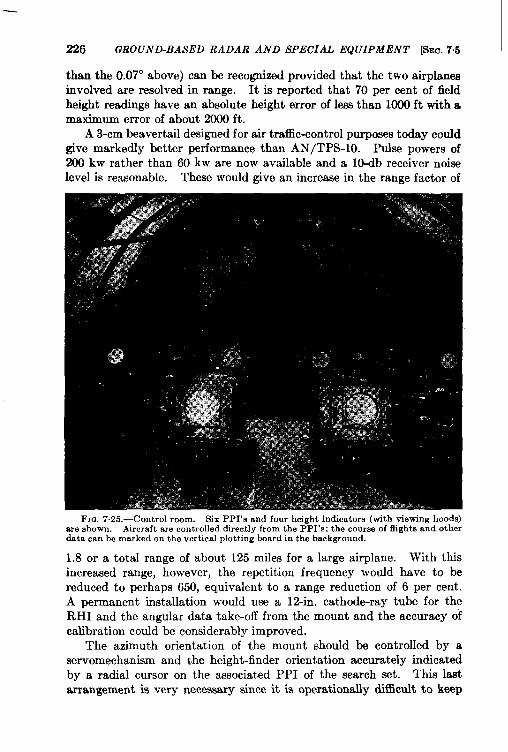
226 GROUNBBASED RADAR AND SPECIAL EQUIPMENT &C. 7,5
than the 0.07° above) can be recognized provided that the two airplanesinvolved are resolved in range. It is reported that 70 per cent of fieldheight readings have an absolute height error of less than 1000 ft with amaximum error of about 2000 ft.
A 3-cm beavertail designed for air traffic-control purposes today couldgive markedly better performance than AN/TPS-10. Puke powers of200 kw rather than 60 kw are now available and a 10-db receiver noiselevel is reasonable. These would give an increase in the range factor of
FI~, 7.25.—Control room. Six PPI’s and four height indicators (with viewing hoods)are shown. Aircraft are controlled directly from the PPI’s; the course of flights and otherdata can he marked on the vertical plotting board in the background.
1.8 or a total range of about 125 miles for a large airplane. With thisincreased range, however, the repetition frequency would have to bereduced to perhaps 650, equivalent to a range reduction of 6 per cent.A permanent installation would use a 12-in. cathode-ray tube for theRHI and the angular data take-off from the mount and the accuracy ofcalibration could be considerably improved.
The azimuth orientation of the mount should be controlled by aservomechanism and the height-finder orientation accurately indicatedby a radial cursor on the associated PPI of the search set. This l~tarrangement is very necessary since it is operationally dlffiwlt to keep
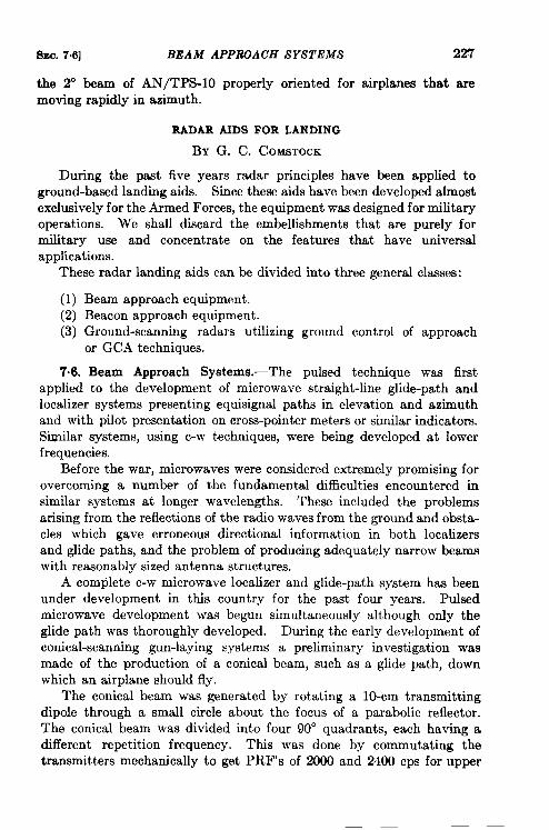
8~C. 7.6] BEAM APPRQACH SYSTEMS 227
the 2° beam of AN/TPS-10 properly oriented for airplanes that aremoving rapidly in azimuth.
WU)AR AIDS FOR LANDING
BY G. C. COMSTOCK
During the past five years radar principles have been applied toground-based landing aids. Since these aids have been developed almostexclusively for the Armed Forces, the equipment was designed for militaryoperations. We shall discard the embellishments that are purely formilitary use and concentrate on the features that have universalapplications.
These radar landing aids can be divided into three general classes:
(1) Beam approach equipment.(2) Beacon approach equipment.(3) Ground-scanning radars utilizing ground control of approach
or GCA techniques.
7.6. Beam Approach Systems.—The pulsed technique was firstapplied to the development of microwave straight-line glide-path andlocalizer systems presenting equisignal paths in elevation and azimuthand with pilot presentation on cross-pointer meters or similar indicators.Similar systems, using c-w techniques, were being developed at lowerfrequencies.
Before the war, microwaves were considered extremely promising forovercoming a number of the fundamental difficulties encountered insimilar systems at longer wavelengths. These included the problemsarising from the reflections of the radio waves from the ground and obsta-cles which gave erroneous directional information in both localizesand glide paths, and the problem of producing adequately narrow beamswith reasonably sized antenna structures.
A complete c-w microwave localizer and glide-path system has beenunder development in this country for the past four years. Pulsedmicrowave development was begun simultaneously although only theglide path was thoroughly developed. During the early development ofconical-scanning gun-laying systems a preliminary investigation wasmade of the production of a conical beam, such as a glide path, downwhich an airplane should fly.
The conical beam was generated by rotating a lo-cm transmittingdipole through a small circle about the focus of a parabolic reflector.The conical beam was divided into four 90° quadrants, each having adifferent repetition frequency. This was done by commutating thetransmitters mechanically to get PRF’s of 2000 and 2400 cps for upper
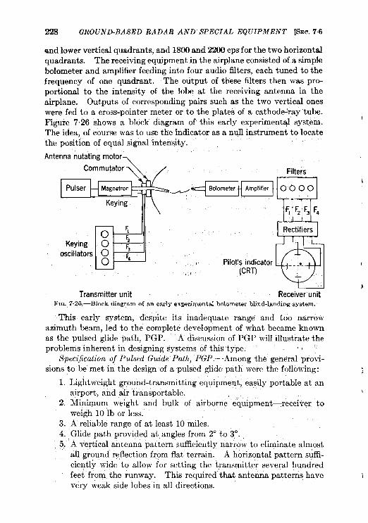
228 GROUND-BASED RADAR AND SPECIAL EQUIPMENT [SEC. 7.6
and lower vertical quadrants, and 1800 and 2200 cps for the two horizontalquadrants. The receiving equipment in the airplane consisted of a simplebolometer and amplifier feeding into four audio filters, each tuned to thefrequency of one quadrant. The output of these titers then was pro-portional to the intensity of the lobe at the receiving antenna in theairplane. Outputs of corresponding pairs such as the two vertical oneswere fed to a cross-pointer meter or to the plates of a cathode-ray tube.Figure 7.26 shows a block diagram of this early experimental system.The idea, of course was to use the indicator as a null instrument to locatethe position of equal signal intensity.
,.Antenna nutating motor
Commutator Filters
Magnetron Bolometer
Keying
o iKeying o ;
oscillators o ;0 ,,
,,i
Transmitterunit ReceiverunitFIG. 7.26.—Block diagram of an early experimental bo~ometer blind-landing system.
This early system, despite its inadequate range and too narrowazimuth beam, led to the compIete development of what became knownas the pulsed glide path, PGP. A dkcussion of PGP will illustrate theproblems inherent in designing systems of this type: ,,
Specification of Pulsed Guide Path, PGP.—Among the’ general provi-sions to be met in the design of a pulsed glide path were the following: .i
1. Lightweight ground-transmitting equipment; easily portable at anairport, and aiir transportable. ),,
2. Minimum weight and bulk of airborne equipment—receiver toweigh 10 lb or less.
3. A reliable range of at least 10 miles.4. Glide path provided at angles from 2° to 3°.5. A vertical antenna pattern sufficiently narrow to eliminate almost,,
all ground reflection from flat terrain. A horizontal pattern suffi-ciently wide to allow for setting the transmitter several hundredfeet’ from the runway. This required that antenna patterns havevery weak side lobes in all directions.
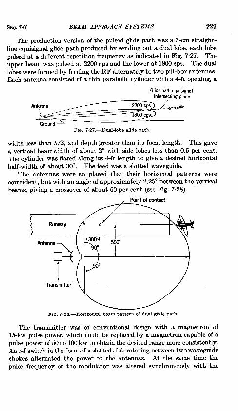
SEC. 7.6] BEAM APPROACH SYSTEMS 229
The production version of the pulsed glide path was a 3-cm straight-line equisignal glide path produced by sending out a dual lobe, each lobepulsed at a different repetition frequency as indicated in Fig. 7“27. Theupper beam was pulsed at 2200 CPSand the lower at 1800 cps. The duallobes were formed by feeding the RF alternately to two pill-box antennas.Each antenna consisted of a thin parabolic cylinder with a 4-ft opening, a
Glkfepath equisignalintersecting plane
Antenna
Ground
FIG. 7.27.—Dual-lobe glide path.
width less than X/2, and depth greater than its focal length. This gavea vertical beamwidth of about 2“ with side lobes less than 0.5 per cent.The cylinder was flared along its 4-ft length to give a desired horizontalhalf-width of about 30°. The feed was a slotted waveguide.
The antennas were so placed that their horizontal patterns werecoincident, but with an angle of approximately 2.25° between the verticalbeams, giving a crossover of about 60 per cent (see Fig. 7“28).
\Runway x
t
Antenna-300’4 ~~,
F’ ~
90°
I
90°
Transmitter
Fm. 7.28.—Horizontal beam pattern of dual glide path.
The transmitter was of conventional design with a magnetron of15-kw pulse power, which could be replaced by a magnetron capable of a
pulse power of 50 to 100 kw to obtain the desired range more consistently.An r-f switch in the form of a slotted disk rotating between two waveguidechokes alternated the power to the antennas. At the same time thepuke frequency of the modulator was altered synchronously with the
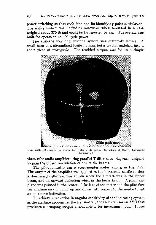
230 13ROUND-BASED RADAR AND SPECIAL EQUIPMENT &c. 7.6
power switching so that each lobe had its identifying pulse modulation.The entire transmitter, includlng antennas, when mounted in a caseweighed about 375 lb and could be transported by air. The system waabuilt for operation on 400-cycle power.
The airborne receiving antenna system was extremely simple. Asmall horn in a streamlined lucite housing fed a crystal matched into ashort piece of waveguide. The rectified output was fed to a simple
FICA 7-29.-Cross-pointer meter for pulse glide path. (Courtesy of Sperru GvroscopeC’ompanu.)
three-tube audio amplifier using parallel-T filter networks, each designedto pass the puked modulation of one of the beams.
The pilot indicator was a cross-pointer meter, shown in Fig. 729.The output of the amplifier was applied to the horizontal needle so thata downward deflection was shown when the aircraft was in the wmerbeam, and an upward deflection when in the lower beam. A smal( ~ir-plane was painted in the center of the face of the meter and the pilot flewthe airplane on the meter up and down with respect to the needle to getan on-course indication.
To achieve a reduction in angular sensitivity of the indicating systemas the airplane approaches the transmitter, the receiver uses an AVC thatproduces a drooping output characteristic for increailng input. It has
SEC. 7.6] BEAM APPROACH SYSTEMS 231
been found necessary to use such a softening of the course indicationwhen flying cross-pointer indication to prevent excessive “hunting” bythe pilot.
Evaluation of Pulsed Beams.—The PGP system as tested at a numberof different airports has the following advantages:
1. Over flat terrain, the glide paths were straight and flyable withsteady needle action that indicated no bends (due to reflections)for glide paths down to 2°. Because the narrow 2° beam with lowside lobes allows little energy to strike the ground near the airport,the glide path is essentially independent of local ground conditionsof moisture, etc.
2. Over obstructions such as hangars, etc., there were considerablyfewer bumps in the path due to reflections than encountered withlower frequency c-w systems.
3. A reliable range of 15 miles is attainable with recent standardtransmitting and receiving techniques.
4. Size and bulk of ground equipment has been reduced to a minimum,offers little hazard to flight, and can be transported from runwayto runway.
5. Airborne equipment is simple and reliable.
The limitations are, in general, the same as those of the c-w beamsystems, namely:
1. Dependence on beam intensity for information, particularly on theconstant crossover of dual beams, is a weakness that can be alle-viated partially by constant ground monitoring of beam positionand by some simple and, if possible, automatic means of correcting“squinting” errors. No monitoring equipment was designed forPGP. Such a step is not inconceivable, however, although it isdifficult to monitor an elevated beam without creating a groundhazard. The type of antennas, feed, and power switching used inmicrowave equipment reduces the likelihood of such beam swingingbut does not entirely eliminate it. Monitoring for localizes wouldpresent fewer complications.
2. Siting problems due to reflections from obstacles, are reduced.3. The equipment gives the pilot no information on the position of
obstacles. The safety of the pilot depends only on whether a clearairport site has been selected. If a poor approach is made he is inlittle danger azimuthally and can make a pull-out at a safe altitudeas indicated by hk altimeter and his knowledge of the terrain.Unfortunately only a few airport runways at which it would bedesirable to make instrument approaches under all-weather flying
232 GROUND-BASED RADAR AND SPECIAL EQUIPMENT [SEC. 77
conditions are as safe as this and then usually in but a single run-way direction per airport.
4. The equipment gives no warning of the presence of other aircrafton the glide path.
5. No information as to range or rate of approach is available to thepilot. Thus, one of the real advantages of pulsed techniques hasgone unused.
6. There is considerable danger of interference between ground sta-tions and of audio jamming of the receiving and indicating equip-ment by other radars unless some form of audio channeling isprovided.
7. The presentation of relative position only on a cross-pointer meterrequires that the pilot have considerable skill and practice in inter-pretation and coordination to obtain the necessary heading andrate of descent for a successful low approach, particularly undercross-wind conditions.
8. The equipment is purely a pilotage device; it supplies no informa-tion to the ground for controlling traffic into or on the final approachzone.
The fundamental advantages discussed above seem to be primarilythose of microwaves and do not show any clear advantage of pukedtechniques over c-w methods in producing pure beam-type glide pathsand localizes as long as stable transmitters and lightweight reliablereceivers are available for both types.
The limitations listed above show that pure beam approach systemsare rudimentary. In the discussions that follow, the real advantages ofradar technique in overcoming some of these limitations are seen.
7.7. Beacon Approach Systems, BABS.-BABS or Radar BA Typeis a radar aid to approach, designed to provide single or multilobedIocalizer and glide paths. Airborne indications showing the position ofthe airplane with respect to these paths includes continuous indication ofthe range from ground-based beacons. The interrogator-responsor iscarried in the aircraft and the indicator may be either a double A-scope(L-scope) or a meter. This system grew out of the need in the early partof the war for systems using available airborne radar gear to replace theinadequate radar aids to approach.
The pilot is “ talked down” by the navigator who gives him the neces-sary information about heading and range. This talk-down procedureis not inherent in the system; the information can be presented to thepilot and copilot directly. Many pilots, however, prefer to have the
information assimilated by some one else so that they can give more
attention to their other fight instruments.
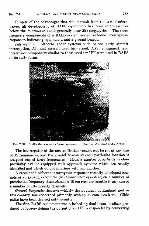
SEC. 77] BEACON APPROACH SYSTEMS, BABS 233
In spite of the advantages that would result from the use of micro-waves, all development of BABS equipment has been at frequenciesbelow the microwave band, generally near 200 megacycles. The threenecessary components of a BABS system are an airborne interrogator-responsor, indicating equipment, and a ground beacon.
in.k-rrogation.-Airborne radar systems such as the early aircraftinterception, AI, and aircraft-to-surface-vessel, ASV, equipment, andinterrogator-responsors similar to those used for IFF were used in BABSin its early forms.
FXQ.7.30.—A ZOO-MCbeacon for beam approach. (Cotmkwu o/ United State. Amrw.)
The interrogator of the newest British version can be set at any oneof 12 frequencies, and the ground beacon at each particular location isassigned one of these frequencies. Thus, a number of airfields in closeproximity can be equipped with approach systems which are readilyidentified and which do not interfere with one another.
A cross-band airborne interrogator-responsor recently developed con-sists of an L-band (about 25 cm) transmitter operating on a number ofpreselected frequency channels and a 10-cm receiver tunable to any one ofa number of lo-cm reply channels.
Ground Responder Beacons. -Early development in England and inthis country was concerned primarily with split-beam localizes. Glidepaths have been devised only recently.
The first BABS equipment was a lashed-up dual-beam localizer pro-duced by lobe-switching the output of an IFF transponder by connecting
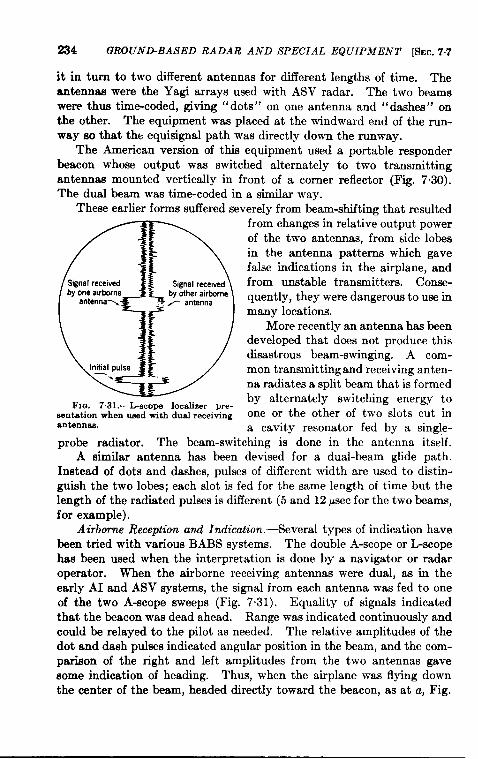
234 GROUND-BASED RADAR AND SPECIAL EQUIPMENT [SEC. 7.7
it in turn to two different antennas for different lengths of time. Theantennas were the Yagi arrays used with ASV radar. The two beamswere thus time-coded, giving “dots” on one antenna and “ dashea” onthe other. The equipment was placed at the windward end of the run-way so that the equisignal path was directly down the runway.
The American version of this equipment used a portable responderbeacon whose output was switched alternately to two transmittingantennas mounted vertically in front of a corner reflector (Fig. 7.30).The dual beam was time-coded in a similar way.
These earlier forms suffered severely from beam-shifting that resulted
FIG. 7.31.—L-stops localizer pre-sentation when used with dual receivingantemnaa.
from changes in relative output powerof the two antennas, from side lobesin the antenna patterns which gavefalse indications in the airplane, andfrom unstable transmitters. Conse-quently, they were dangerous to use inmany locations.
More recently an antenna has beendeveloped that does not produce thisdisastrous beam-swinging. A com-mon transmitting and receiving anten-na radiates a split beam that is formedby alternately switching energy toone or the other of two slots cut ina cavity resonator fed by a single-
probe radiator. The beam-switching is done in the antenna itself.A similar antenna has been devised for a dual-beam glide path.
Instead of dots and dashes, pulses of different width are used to distin-guish the two lobes; each slot is fed for the same length of time but thelength of the radiated pulses is different (5 and 12 psec for the two beams,for example).
Airborne Reception and Indication. -Several types of indication havebeen tried with various BABS systems. The double A-scope or L-scopehas been used when the interpretation is done by a navigator or radaroperator. When the airborne receiving antennas were dual, as in theearly AI and ASV systems, the signal from each antenna was fed to oneof the two A-scope sweeps (Fig. 7.31). Equality of signals indicatedthat the beacon was dead ahead. Range was indicated continuously andcould be relayed to the pilot as needed. The relative amplitudes of thedot and dash pulses indicated angular position in the beam, and the com-parison of the right and left amplitudes from the two antennas gavesome indication of heading. Thus, when the airplane was l-lying downthe center of the beam, headed directly toward the beacon, as at a, Fig.
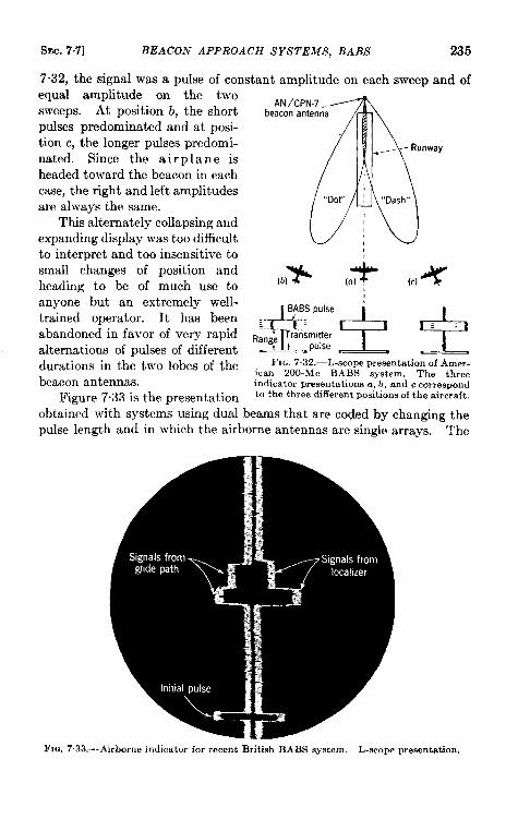
SEC. 7.7] BEACON APPROACH SYSTEMS, BABS 235
7.32, the signal was a pulse of constant amplitude on each sweep and ofequal amplitude on the twosweeps. At position b, the shortpukes predominated and at posi-tion c, the longer pulses predomi-nated. Since the airplane isheaded toward the beacon in eachcase, the right and left amplitudesare always the same.
This alternately collapsing andexpanding display was too difficultto interpret and too insensitive tosmall changes of position andheading to be of much use toanyone but an extremely well-trained operator. It has beenabandoned in favor of very rapidalternations of pulses of differentdurations in the two lobes of thebeacon antennas.
Figure 7.33 is the presentation
J!tAN/cPN-7 -
beacon antenna
Runway
“DoY’ ; “Dash”
FIG. 7.32.—L-scope presentation of Amer-ican ZOO-MC BABS system. The threeindicator presentations a, b, and c correspondto the three different positions of the aircraft.
obtained with systems using dual beams that are coded by changing thepulse length and in which the airborne antennas are single arrays. The
FIG. 7.33.--Airborne indicator for recent British BABS system. L-scope presentation.
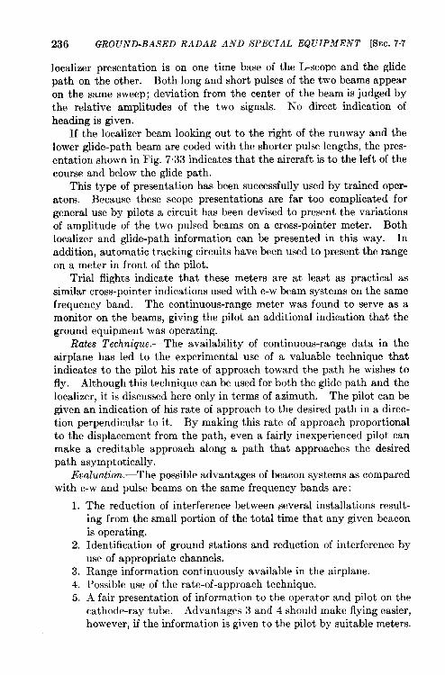
236 GROUND-BASED RADAR AND SPECIAL EQUIPMENT [&3C.7.7
localizer presentation is on one time base of the L-scope and the glidepath on the other. Both long and short pulses of the two beams appearon the same sweep; deviation from the center of the beam is judged bythe relative amplitudes of the two signals. No direct indication ofheading is given.
If the localizer beam looking out to the right of the runway and thelower glide-path beam are coded with the shorter pulse lengths, the pres-entation shown in Fig. 733 indicates that the aircraft, is to the left of thecourse and below the glide path.
This type of presentation has been successfully used by trained oper-at ors. Because these scope presentations are far too complicated forgeneral use by pilots a circuit has been devised to present the variationsof amplitude of the two pulsed beams on a cross-pointer meter. Bothlocalizer and glide-path information can be presented in thk way. Inaddition, automatic tracking circuits have been used to present the rangeon a meter in front of the pilot.
Trial flights indicate that these meters are at least as practical assimilar cross-pointer indications used with c-w beam systems on the samefrequency band. The continuous-range meter was found to serve as amonitor on the beams, giving the pilot an additional indication that theground equipment was operating.
Rates Technique.—The availability of continuous-range data in theairplane has led to the experimental use of a valuable technique thatindicates to the pilot his rate of approach toward the path he wishes tofly. Although this technique can be used for both the glide path and thelocalizer, it is discussed here only in terms of azimuth. The pilot can begiven an indication of his rate of approach to the desired path in a direc-tion perpendicular to it. By making this rate of approach proportionalto the displacement from the path, even a fairly inexperienced pilot canmake a creditable approach along a path that approaches the desiredpath asymptotically.
Evaluation.—The possible advantages of beacon systems as comparedwith c-w and pulse beams on the same frequency bands are:
1. The reduction of interference between several installations result-ing from the small portion of the total time that any given beaconis operating.
2. Identification of ground stations and reduction of interference byuse of appropriate channels.
3. Range information continuously available in the airplane.4. Possible use of the rate-of-approach technique.5. A fair presentation of information to the operator and pilot on the
cathode-ray tube. Advantages 3 and 4 should make flying easier,however, if the information is given to the pilot by suitable meters.
f!lEc. 78 GROUND-BASED SCANNING RADAR SYSTEMS 237
Its disadvantages with respect to other beam systems on similar fre-quencies are that:
1. The inclusion of additional functions makes the airborne equip-ment heavier, bulkier, and more complicated than simple beamreceiving equipment.
2. Cathode-ray tube information can be used to best advantage onlyby a highly trained radar operator and a pilot working together.This characteristic limits its use in civilian flying.
The possibilities of microwave BABS equipment would seem to givethe added advantages over the lower-frequency system, discussed in theprevious section. Airborne microwave interrogator-responders are fea-sible but would probably be heavier.
The beacon technique is well-advanced. Microwave beacons usedwith proper antennsa could produce dual glide paths and localizes thatwould reduce the reflection and siting problems encountered at lowerfrequencies.
Although it is clear from the above dkcussion that systems of theBABS type are improved beam systems, they are subject to some of thefundamental limitations already noted, namely:
1. Dependence of the reliabilityy of the information on constancy of theintensities of the beams.
2. Lack of means for warning pilots of obstacles.3. Lack of means for giving warning of the presence of other aircraft
on the glide path.4. Complication of airborne indication.5. Limited information available for traffic control.
Beacons have been used experimentally for a method of handlingtraffic in which the pilot is notified to circle the airport at a given constantrange from the beacon. A holding pattern of concentric circles is thenformed in which airplanes are flying circular paths at different fixedranges. They are then successively cleared from inner circles into finalapproach.
7.8. Ground-based Scanning Radar Systems.—A significant contri-bution to instrument landing made during the war was the use of ground-based scanning radar for obtaining accurate relative position of a landingairplane with respect to a safe path of descent to a runway, combinedwith “talk-down” techniques for giving information and instructions forlanding to the pilot by voice radio.
The prime equipment produced for these purposes was the groundcontrol of approach system, GCA, built in considerable quantities in thiscountry for use by the United States Army and Navy, and by the British.
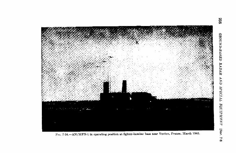
238G
RO
UN
D-B
ASE
DR
AD
AR
AN
DSP
EC
IAL
EQ
UIP
ME
NT
[SE
C.
7.8
SEC. 7.8] GROUND-BASED SCANNING RADAR SYSTEMS 239
Inthelater phases of thewarin the European, Aleutian, and Pacifictheaters GCA (AN/MPN-1) proved to beaversatile emergency landingfacility that could be used by any type of aircraft. It was used withsafety even by relatively inexperienced instrument pilots under conditionsof ceiling and visibility worse than those that would permit use of thefixed-beam system. The GCA, having served with distinction duringthe later stages of the war, emerges as an important weapon in the battlefor achieving all-weather civilian flying.
The basic concepts of the GCA system—its method of obtaining dataon the position of the airplane relative to the runway, the kind of dataobtained, and the method of presentation to the pilot—all depart radicallyfrom traditional glide-path-localizer techniques developed before the war.
The AN/MPN-l (see Fig. 7.34) is a self-contained mobile unit con-sisting of two radars, a 10-cm search radar, and a 3-cm sector-scanningsystem that covers a limited volume of space surrounding the final pathof descent. All equipment is compactly housed in an operations trailer.The trailer contains the two radars and the operating positions for thecrew of six: four scope operators, the controller of the final approach,and the crew supervisor (Fig. 7.35). Since AN/MPN-l was designedas a complete control unit in itself for use in forward areas, the trailercontains complete radio equipment for communicating with both landingaircraft and the control towers at the airport. The truck contains theprime power generators, air-conditioning units, tools, etc.
The primary function of the search system is to detect and identifyindividual airplanes coming into the landing zone and, by instructingthe pilot over voice radio, to guide the airplane through an approachpattern into a rough alignment with the final descent path at a distanceof from 4 to 10 miles from the field. The search set thus feeds the air-plane into the region where the 3-cm scanning beams are operating andwhere the pilot receives more precise information as to his position.
The search antenna was designed to cover those regions in which air-planes approach the airport for a landing. It was not meant to providehigh angle coverage over the airport for airplanes passing through theregion. The antenna consists of an 8-ft linear dipole array which feedsa semicylindrical reflector with parabolic cross section, both mountedvertically on top of the trailer. The beamwidth is approximately 5°in azimuth with a cosecant-squared coverage extending in elevation from3° to 10° above the horizon. The peak of the beam is normally at the3° angle of elevation in order to minimize ground clutter. The require-ment for frequent search information when airplanes have to be controlledaccurately at short ranges, 10 to 30 miles, is met by scanning the searcharray through 360° in azimuth at 30 rpm. With a transmitted pulsepower of 100 kw the search system is capable of detecting airplanes at
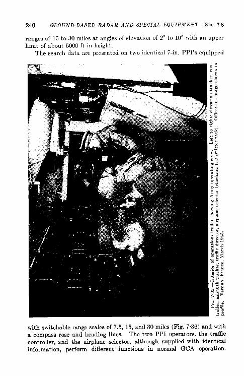
240 GROUND-BASED RADAR AND SPECIAL EQUIPMENT [SEC. 78
ranges of 15 to 30 miles at angles of elevation of 2° to 10° with an upper
limit of about 5000 ft in height.
The search data are presented on two identical 7-in. PPI’s equipped
with switchable range scales of 7.5, 15, and 30 miles (Fig. 7.36) and witha compass rose and heading lines. The two PPI operators, the trafficcontroller, and the airplane selector, although supplied with identicalinformation, perform different functions in normal GCA operation.
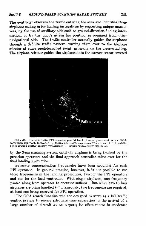
SEC.-7.8] GW.OUND-BASED SCANNING RADAR SYSTEMS 241
The controller observes the traffic entering the area and identifies thoeeairplanes calling in for lantig bstructiom by requesting unique maneu-vers, by the use of auxiliary aids such as ground-direction-finding infor-mation, or by the pilot’s giving his position as obtained from othernavigational aids. The traffic controller normally guides the airplanesthrough a definite trafEc pattern, turning them over to the airplaneselector at some predetermined point, generally on the cross-wind leg.The airplane selector guides the airplanes into the narrow sector covered
FIG 7.36.—Photo of GCA PPI showing ground track of an airplane making a ground-controlled approach (obtained by taking eucceseive exposures every 4 sec of PPI aignala,hence ground clutter greatly overexposed). Range circles every two miles.
by the 3-cm scanning system until the airplane is being tracked by theprecision operators and the final approach controller takes over for thefired landing instruction.
Separate communication frequencies have been provided for eachPPI operator. In general practice, however, it is not possible to usethree frequencies in the landing procedures, two for the PPI operatorsand one for the final controller. With single airplanes, one frequencypassed along from operator to operator suffices. But when two to fourairplanes are being handled simultaneously, two frequencies are required,at least one being reserved for PPI operation.
The GCA search function was not designed to serve as a full trafficcontrol system to ensure adequate time separation in the arrival of alarge number of aircraft at an airport; its effectiveness in moderate
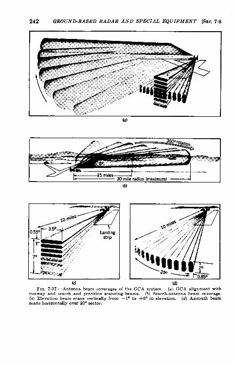
242 GROUND-BASED RADAR AND SPECIAL EQUIPMENT ISEC. 7.8
(a)
(b)
D.55°
(c) (d)FIG. 7,37.—Antenna beam coverazes of the GCA svstem. (a) GCA alienment with
runway and search and precision scanning beams. (bj Search-antenna be~m coverage.(c) Elevation beam scans vertically from – 1“ to +6° in elevation. (d) Azimuth beamscans horizontally over 20° sector.
am 7.8] GROUND-BASED SCANNING RADAR SYSTEMS 243
traffic must not be underestimated, however. When airplanes arriveevery 3 ruin or when the situation is such that the traffic controllercan pull out the bottom airplane from a stack of planes every 3 rein,15 to Xl airplanes can land per hour by the use of GCA.
The GCA system is the first landing aid that has been used to helpsolve the approach zone traffic problem by effectively feeding airplanesinto the final approach. For the first time, quantitative navigationalinformation is available to the pilot when outside the narrow sector ofthe descent path. As a result the time-consuming procedures of orienta-tion and bracketing on range legs and localizes are eliminated.
The final letdown approach to visual contact with the runway isobserved with the 3-cm system, generally referred to as the precisionsystem. Two narrow fan beams, one scanning in azimuth and the otherin elevation, locate the airplane in an area 20° wide in azimuth up to 6°above the horizon in elevation, and within a range of 10 miles. Figure7.37 shows the coverage of the three antenna beams of the GCA. Theelevation beam has a one-way half-power width of 0.55° in elevationand 3.5° in azimuth. The azimuth beam has a one-way half-powerwidth of 0.85° in azimuth and 2.0° in elevation. The approximatelocation of the trailer on the field is shown in the figure. The unit isnormally sited on the right-hand side of the runway (looking out towardthe airplane approaching at the upwind end of the landing strip), 200 to500 ft from the center of the runway, and 2000 to 4000 ft down the stripfrom the approach end so that the airplane can be ‘ 1seen” to touchdown.The coverage of the azimuthal scan is from 5° on the right side to 15° onthe left side of a line parallel to the center line of the runway and runningthrough the center of the trailer.
These fan beams are each produced by a dipole array that is fed by asqueezable waveguide placed along the focal line of a semicylindricalreflector of parabolic cross section. Figure 7.38 shows the combinationof the two antenna arrays and a cross section of the waveguide portionof the arrays. The beam is scanned electrically by varying the width ofthe waveguide periodically—that is, by moving one of its sides parallelto itself. The two arrays are alternately fed power from the same trans-mitter. The scan cycle is such that each antenna beam sweeps througha complete cycle (two looks) in 2 sec. A scan rate four times as fastas this is available for operation at short range.
The data received from each of the precision scans is presented on aseparate pair of 7-in. expanded partial PPI’s, one having a 10-mile rangeand the other a 2-mile range, that is, a five-fold expansion of the final 2miles. Two operators, the azimuth tracker and the elevation trackerfollow the airplane signal on their respective pairs of indicators. M ov-able lighted cursors (Fig. 7041 shows an elevation cursor) superimposed
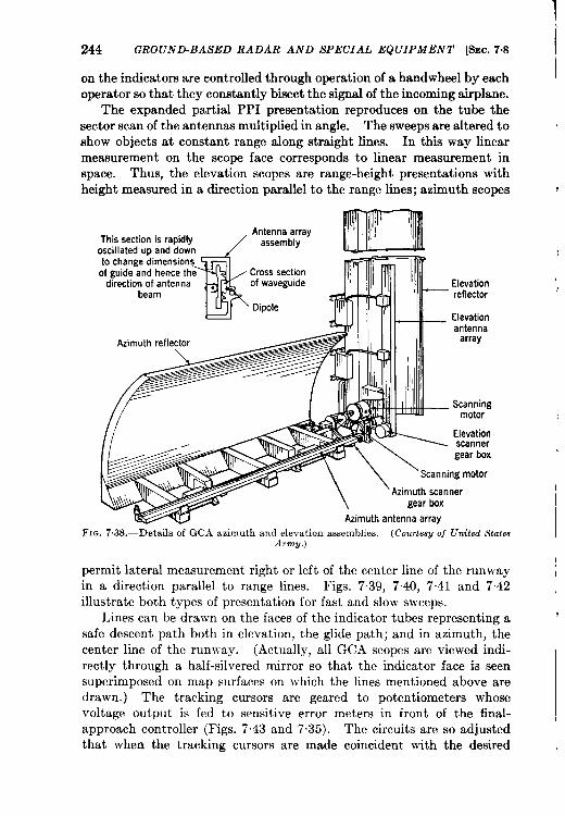
244 GROUND-BASED RADAR AND SPECIAL EQUIPMENT [SEC.7.8
on the indicators are controlled through operation of a handwheel by eachoperator so that they constantly bisect the signal of the incoming airplane.
The expanded partial PPI presentation reproduces on the tube thesector scan of the antennas multiplied in angle. The sweeps are altered toshow objects at constant range along straight lines. In this way linearmeasurement on the scope face corresponds to linear measurement inspace. Thus, the elevation scopes are range-height presentations withheight measured in a direction parallel to the range lines; azimuth scopes
This sectionAntenna array
oscil Iated upassembly
to change diof guide and Cross section
direction of of waveguldebea
Dipole
F=-
Elevationreflector
Elevationantenna
array
_ Scanning
\\ Azimuth scanner
gear box
Azimuth antenna array
FIG. 7,38.—Details of GCA azimuth and elevation assemblies. (CourtesU of United StatesArmV.)
permit lateral measurement right or left of the center line of the runwayin a direction parallel to range lines. Figs. 7.39, 7.40, 7.41 and 7.42illustrate both types of presentation for fast and slow sweeps.
Lines can be drawn on the faces of the indicator tubes representing asafe descent path both in elevation, the glide path; and in azimuth, thecenter line of the runway. (Actually, all GCA scopes are viewed indi-rectly through a half-silvered mirror so that the indicator face is seensuperimposed on map surfaces on which the lines mentioned above aredrawn.) The tracking cursors are geared to potentiometers whosevoltage output is fed to sensitive error meters in front of the final-approach controller (Figs. 7.43 and 7.35). The circuits are so adjustedthat when the tracking cursors are made coincident with the desired
I
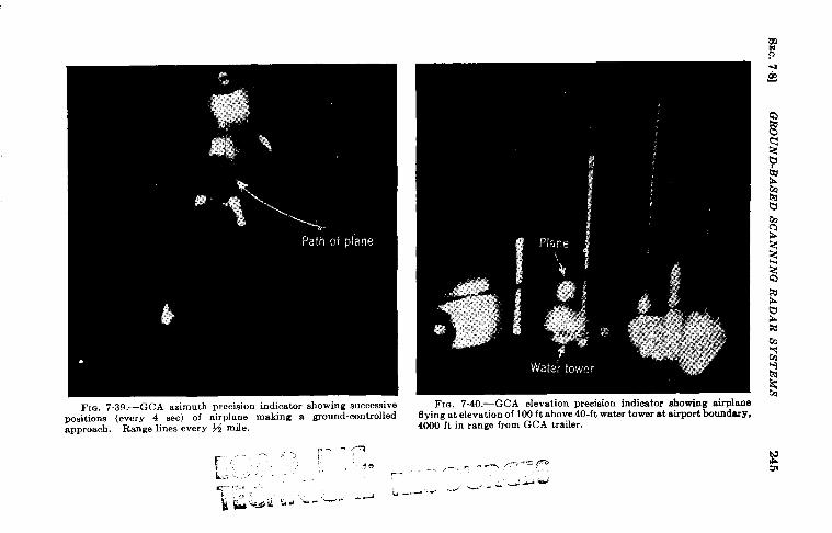
FIG. 7.39 .—GCA azimuth precisiOn indicatOr shOwingsuccessivepositions (every 4 see) of airplane making a ground-controlledapproach. Range lines every M mile.
- XTr--’ ,r- - - .-”’, ,
FIQ. 7.40.—GCA elevation precision indicator showing airplaneIIying at elevation of 100 ft above 40-ft water tower at airport boundary,4000 ft in range from GCA trailer.
“ - ,-{ ,-. P-., p. - ,-
._ d -’..-, k, - -
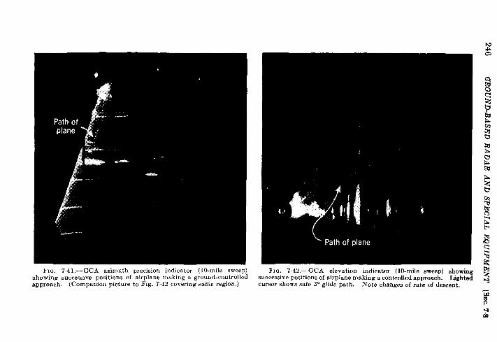
N
FIG. 7.41.—GCA azimuth precision indicator (l O-mile sweep) FIC. 7.42.—GCA elevation indicator (10-mile sweep) showingshowing successive positions of airplane making a ground-controlled successive positions of airplane making a contmlled approach. Lighted g
apprOach. (COmpanion picture to Fig. 7.42 covering same region.) cursor shows safe 3° glide path. Note changes of rate of descent.
~~-ado
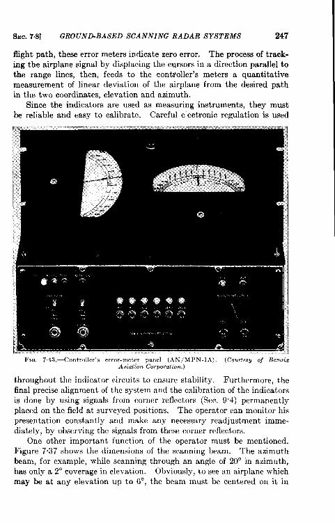
SEC. 7,8] GROUND-BASED SCANNING RADAR SYSTEMS 247
flight path, these error meters indicate zero error. The process of track-ing the airplane signal by displacing the cursors in a direction parallel tothe range lines, then, feeds to the controller’s meters a quantitativemeasurement of linear deviation of the airplane from the desired pathin the two coordinates, elevation and azimuth.
Since the indicators are used as measuring instruments, they mustbe reliable and easy to calibrate. Careful electronic regulation is used
FIQ. 7.43, —ControUer’s error-meter panel (AN[MPN-lA), (Courte8y of BendizAviation Corporation.)
throughout the indicator circuits to ensure stability. Furthermore, thefinal precise alignment of the system and the calibration of the indicatorsis done by using signals from corner reflectors (Sec. 9.4) permanentlyplaced on the field at surveyed positions. The operator can monitor hispresentation constantly and make any necessary readjustment imme-diately, by observing the signals from these corner reflectors.
One other important function of the operator must be mentioned.Figure 7.37 shows the dimensions of the scanning beam. The azimuthbeam, for example, while scanning through an angle of 20° in azimuth,has only a 2° coverage in elevation. Obviously, to see an airplane whichmay be at any elevation up to 6°, the beam must be centered on it in
248 GROUND-BASED RADAR AND SPECIAL EQUIPMENT @nC. 743
elevation by tilting the whole azimuth antenna assembly around ahorizontal axis. This is done by the elevation tracker who controls theelevation adjustment of the azimutn antenna by foot pedals in the indi-cator rack. The position of the antenna is indicated on his cathode-raytube by an additional transparent cursor linked to his foot pedals. Bykeeping the cursor roughly aligned on the airplane signal, the elevationtracker makes sure that the azimuth operator can see this signal on hisindicator. A similar arrangement permits the azimuth tracker to adjustthe position of the elevation antenna in azimuth. (In Fig. 7“42 theantenna-follower cursor is clearly shown.)
The final controller has available on his error meters the linear devia-tion of the airplane in azimuth and elevation from the desired path andcan obtain from either of his trackers continuous data on the range of theairplane. By observing the motion of his error-meter needles, he getsan indication of the rate of closing to the path. From these data andobservations on wind drift he controls the descent of the airplane bygiving instructions to the pilot on the changes in heading and rate ofdescent necessary to keep the airplane on the proper path. He warns thepilot of the presence of any aircraft on collision courses and of his prox-imity to dangerous obstacles on the ground. It is his responsibility togive orders to pull the airplane out of its approach if at the specified safeminimum altitude the airplane is not in a proper position to land or ifthere is evidence that ground equipment is malfunctioning. Since he isacting as the pilot’s “second brain” he must be very familiar with thelanding characteristics of various aircraft and the landing procedures.The entire crew must be carefully trained and ever alert to the variousemergencies that arise in instrument landing.
Advantages and Limitations.—GCA equipment was used with phenom-enal success during its first year of operation. It made possible severalthousand instrument approaches and numerous emergency landingsunder conditions of very poor visibility. and often with pilots who hadnever previously made an approach under GCA supervision. Thisrecord indicates that the system possesses a number of exceptionalattributes lacking in other landing aids.
1. Since it feeds information to the pilot over normal radio com-munications, the system requires no additional specialized gearin the airplane. It can therefore be considered a universalsystem if the proper communication channels are made available.
2. The information received aurally by the pilot requires littleinterpretation of data on his part because he does not have topay close attention to additional meters or CRT’s and is relievedof part of the burden placed upon him by the instrument flyingcondition.
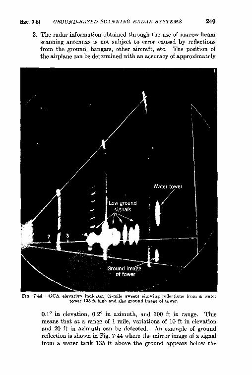
250 GROUND-BASED RADAR AND SPECIAL EQUIPMENT [SEC. 7.8
ground level. Ground-reflected energy that reaches the airplaneand is returned is thus separated from the direct signal responseuntil the airplane is less than 0.2° from the ground.
4. Signals from fixed objects close to the desired landing path,instead of being harmful, provide the ground crew with informa-tion as to the proximity of the airplane to these objects and thepilot can be told how to avoid them. Figure 7.40 shows theairplane signal clearly resolved from the ground return as itpasses over a 40-ft tower with a clearance of 100 ft at a range of4000 ft. Figure 7.39 shows the azimuth track of an airplanewhich has flown over the same obstacle.
5. The operators can give aid to all types of aircraft and provideglide paths within the range of 2° to 5° simply by realigning theelevation-tracking cursor to coincide with the proper glide-pathline drawn on the map face.
6. The radar scope presentations permit constant monitoring of thealignment of the system, a tremendous safety factor that helps toincrease the pilot’s confidence in the system.
7. The system is provided with standby dual channel equipment forall components except antenna arrays and indicators so that arapid changeover can be made upon failure of components inuse.
8. The fact that the unit can be moved from runway to runwayeliminates the inflexibility of single runway operation requiredwith most landing aids. Any necessary realignment of equipment can be accomplished within half an hour.
9. It can be used by tired pilots or those who have had little or noprevious experience with the equipment. Indoctrination ofpilots and a few preliminary flights, however, help to familiarizethe pilot with the procedure and establish his confidence in itsreliabilityy.
10. The traffic-handling capacity of the system is as great as that ofany other landing aid that has been proposed and is greatlyenhanced by its unique partial traffic control provided by thesearch system.
The following limitations have most frequently been pointed out bythe critics of GCA: (a) large, highly skilled crews are needed for 24-hrservice; (b) the system does not include a completely satisfactory identi-fication system; (c) multichannel communication is required for landingsin traffic of high density, particularly for closely adjacent fields; (d)there is the problem of language when GCA is used by pilots of differenttongues; (e) the rate of landing is limited to one aircraft every 2 to 3
SEC. 7.8] GROUND-BASED SCANNING RADAR SYSTEMS 251
ruin; this is not a limitation under present traffic conditions but maydevelop into one.
Some of these limitations are being alleviated by improvements andnew developments. The inadequacy of present communication facilitieswill be reduced with the widespread use of very-high-frequency muki-channel equipment. The language problem, already present in normalcontrol tower operation, suggests that universal codes could be devisedfor the talk-down procedure.
The identification problem is greatly improved by presenting directlyon the GCA indicators azimuth-bearing information obtained by radiodirection finders.
The greatest progress in decreasing the requirement for operators, inincreasing the traffic capacity of the system, and in improving the controlinformation would result from direct reading of the indicators of theprecision system by the controller. Although in the AN/MPN-l thecontroller was placed between the two trackers in the expectation that hecould view the scopes directly, the physical arrangement made it difficultfor him to do so. Operational experience in controlling airplanes byusing the azimuth and elevation indicators directly either by having bothoperators give instructions to the pilot alternately or having a singlecontroller observe both indicators, has proved that there are considerableadvantages to this procedure. Shorter controlled runs can be madewith greater accuracy when the controller can observe the interrela-tion between the signal trails and the desired flight paths directly andinstant 1y.
One manufacturer is developing a single tube on which both azimuthand elevation signals will be displayed simultaneously. It is hoped thatthis will permit reduction of the present team of three men for the pre-cision system to a single controller. In regions of heavy traffic wherelandings at the rate of one per minute are desired, these indicators couldbe duplicated and a second controller could give instructions to a secondairplane on the glide path.
Many instrument approaches are made under conditions that do notrequire the use of the full precision team, for instance, with ceilings of500 ft or more and visibility of 1 mile. In many locations, descent undersuch conditions can be effectively controlled from the PPI alone if thepilot is told what his elevation should be as he approaches the field. If aremote PPI were to be provided in the control tower, such informationcould be used to speed up traffic by reducing the number of missedapproaches that result from poor alignment in letdowns relying solelyon radio range and localizes. The addition of the surveillance fea-ture provided by ground radar is a must in future instrument landingprocedures.
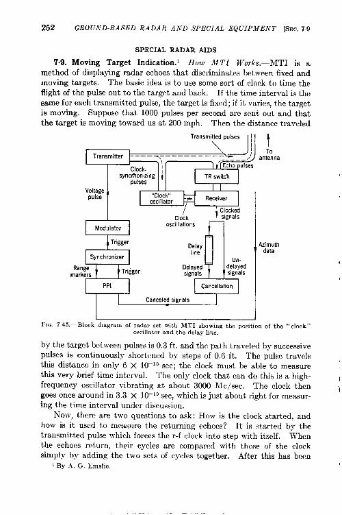
252 ~ROfJND.BASED RADAR AND SPECIAL EQUIpMENT [SEO.7.9
SPECIAL RADAR AIDS
7.9. Moving Target Indication.’ How MTI Works.—MTI is amethod of displaying radar echoes that discriminates between fixed andmoving targets. The basic idea is to use some sort of clock to time theflight of the pulse out to the target and back. If the time interval is thesame for each transmitted pulse, the target is fixed; if it varies, the targetis moving. Suppose that 1000 pulses per second are sent out and thatthe target is moving toward us at 200 mph. Then the distance traveled
~=ani’na
I...
syncrhonizing ~pulses lJ!W!J
8
Modulator
Trigger
Synchronizer
Range Triggermarkers
PPI )!3Delayhne
Un-Delayed delayedsignals signals
Cancellation
I1
Canceled signals
~FIG. 745.-Block dmgram of radar set with MTI showing the position of the “ clock”
oscillator and the delay line.
by the target between pulses is 0.3 ft. and the path traveled by successive
pulses is continuously shortened by steps of 0.6 ft. The pulse travelsthis distance in only 6 X 10⁻¹⁰ sec; the clock must be able to measure
this very brief time interval. The only clock that can do this is a high-frequency oscillator vibrating at about 3000 Me/see. The clock then
goes once around in 3.3 X 10⁻¹⁰ see, which is just about right for measur-
ing the time interval under discussion.
Now, there are two questions to ask: How is the clock started, and
how is it used to measure the returning echoes? It is started by the
transmitted pulse which forces the r-f clock into step with itself. When
the echoes return, their cycles are compared with those of the clock
simply by adding the two sets of cycles together. After this has been
i By .4, G. Emslie.
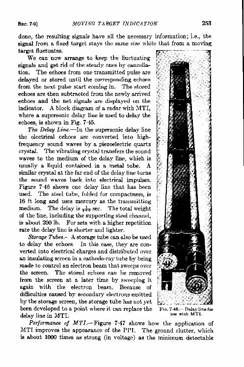
sm. 7.9] MOVING TARGET INDICATION 253
done, the resulting signals have all the necessary information; i.e., thesignal from a fixed target stays the same size while that from a movingtarget fluctuates.
We can now arrange to keep the fluctuatingsignals and get rid of the steady ones by cancella-tion. The echoes from one transmitted pulse aredelayed or stored until the corresponding echoesfrom the next pulse start coming in. The storedechoes are then subtracted from the newly arrivedechoes and the net signals are displayed on theindicator. A block diagram of a radar with MTI,where a supersonic delay line is used to delay theechoes, is shown in Fig. 745.
Tb Delay Line. -In the supersonic delay linethe electrical echoes are converted into high-frequency sound waves by a piezoelectric quartzcrystal. The vibrating crystal transfers the soundwaves to the medium of the delay line, which isusually a liquid contained in a metal tube. Asimilar crystal at the far end of the delay line turnsthe sound waves back into electrical impulses.F@re 7.46 shows one delay line that has beenused. The steel tube, folded for compactness, is16 ft long and uses mercury as the transmittingmedium. The delay is& sec. The total weightof the line, including the supporting steel channel,is about 200 lb. For sets with a higher repetitionrate the delay line is shorter and lighter.
Stor~e Tubes.—A storage tube can also be usedto delay the echoes. In this case, they are con-verted into electrical charges and distributed overan insulating screen in a cathode-ray tube by beingmade to control an electron beam that sweeps overthe screen. The stored echoes can be removedfrom the screen at a later time by sweeping itagain with the electron beam. Because ofdifficulties caused by secondary electrons emittedby the storage screen, the storage tube has not yetbeen developed to a point where it can replace thedelay line in MTI.
FIG.7.46.—Delay line forUm with MTI.
Pmjomnunce of MTI.—F@re 7.47 shows how the application ofMTI improves the appearance of the PPI. The ground clutter, whichis about 1000 times as strong (in voltage) as the minimum detectable
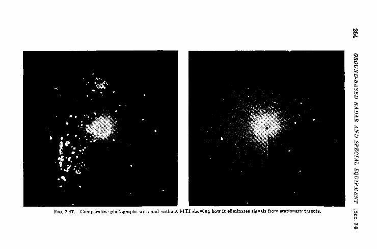
254Q
RO
UN
BB
AS
ED
RA
DA
RA
ND
SP
EC
IAL
EQ
UIP
ME
NT
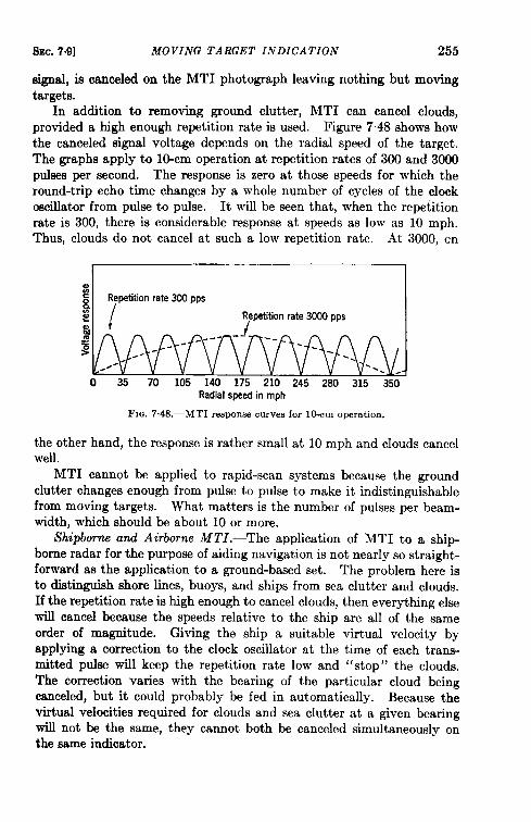
SEC.7-9] MOVING TARGET INDICATION 255
signal, is canceled on the MTI photograph leaving nothing but movingtargets.
In addition to removing ground clutter, MTI can cancel clouds,provided a high enough repetition rate is used. Figure 7“48 shows howthe canceled signal voltage depends on the radial speed of the target.The graphs apply to lo-cm operation at repetition rates of 300 and 3000pulses per second. The response is zero at those speeds for which theround-trip echo time changes by a whole number of cycles of the clockoscillator from pulse to pulse. It will be seen that, when the repetitionrate is 300, there is considerable response at speeds as low as 10 mph.Thus, clouds do not cancel at such a low repetition rate. At 3000, on
;~{%g.g
o 35 70 105 140 175 210 245 280 315 350Radial speedinmph
FIG.7.48.—MTIresponse curves for 10-cm operation.
the other hand, the response is rather small at 10 mph and clouds cancelwell.
MTI cannot be applied to rapid-scan systems because the groundclutter changes enough from pulse to pulse to make it indistinguishablefrom moving targets. What matters is the number of pulses per beam-width, which should be about 10 or more.
Shipborns and Airborne MTI.—The application of MTI to a ship-borne radar for the purpose of aiding navigation is not nearly so straight-forward as the application to a ground-based set. The problem here isto distinguish shore lines, buoys, and ships from sea clutter and clouds.If the repetition rate is high enough to cancel clouds, then everything elsewill cancel because the speeds relative to the ship are all of the same
order of magnitude. Giving the ship a suitable virtual velocity byapplying a correction to the clock oscillator at the time of each trans-mitted pulse will keep the repetition rate low and “stop” the clouds.The correction varies with the bearing of the particular cloud beingcanceled, but it could probably be fed in automatically. Because thevirtual velocities required for clouds and sea clutter at a given bearingwill not be the same, they cannot both be canceled simultaneously onthe same indicator.
256 GROUND-BASED RADAR AND SPECIAL EQUIPMENT [SEC. 7.10
For aerial navigation, clouds should be eliminated and landmarksretained. Thus, the problem is similar to that just discussed but withemphasis on the high virtual velocity that an aircraft must have to makea cloud “stop. ” This condition poses a difficult technical problemfor which no practical solution has yet appeared.
7.10. Beacons.’ Use oj Airborne Beacons for Navigation-Thefunction of an airborne beacon is to reply, when interrogated by a groundradar, with a pulse or a series of pulses which can be received by theground radar. A general description of radar beacons may be found inSec. 1.9. Airborne beacons have been built in the 3000-Mc/sec regionwhich can be seen at 300 miles by high-powered ground radars. They arecoded for identification, weigh less than 40 lb, and require about 150watts of power; similar beacons, slightly heavier and requiring morepower, have been built in the 10,000-Mc/sec region. Beacons weighingas little as 7 lb have been built for operation at 200 Me/see, but theirazimuth resolution is poor.
The advantages of using beacons are:
1. Range. The beacon reply is generally much stronger than thenatural radar echoes from the same aircraft. Originally, airbornebeacons were used to increase the range at which an aircraft couldbe seen. With the advent of high-powered long-range groundradars, this increase in range has become relatively less important.
2. Identification. Using the coding systems described in Chap. 1,each aircraft carrying a beacon can be identified.
3. Elimination of extraneous echoes. If the beacon does not replyon the radar transmitter frequency, the radar is insensitive tonormal echoes when its receiver is tuned to the beacon frequency.Hence, ground clutter does not appear.
4. Communication. Since it is fairly easy to obtain a much largernumber of codes than are necessary for aircraft identification,those remaining can be used for communication. This does notgive the complete flexibility of voice communication, but doesallow a large number of standardized messages to be handled—the reporting of aircraft altitude, for example. The various codingsystems may also be applied to the radar signals which interrogatethe beacon, making radar-to-beacon communication possible.In its present state the decoding equipment would probably betoo heavy to justify its installation in an aircraft, but futuredevelopments and demands may alter this situation. Radar-to-beacon communication can be applied more easily when the radar“searchlights” the target than when it scans.
1By J. B. Platt and R. M. Whitmer.
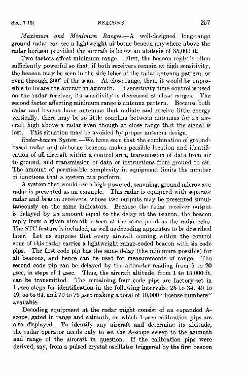
SEC. 7.10] BEACONS 257
Maximum and Minimum Ranges.—A well-designed long-rangeground radar can see a lightweight airborne beacon anywhere above theradar horizon provided the aircraft is below an altitude of 35,000 ft.
Two factors affect minimum range. First, the beacon reply is oftensufficiently powerful so that, if both receivers remain at high sensitivity,the beacon may be seen in the side lobes of the radar antenna pattern, oreven through 360° of the scan. At close range, then, it would be impos-sible to locate the aircraft in azimuth. If sensitivity time control is usedon the radar receiver, its sensitivity is decreased at close ranges. Thesecond factor affecting minimum range is antenna pattern. Because bothradar and beacon have antennas that radiate and receive little energyvertically, there may be so little coupling between antennas for an air-craft high above a radar even though at close range that the signal islost. This situation may be avoided by proper antenna design.
Radar-beacon System.—We have seen that the combination of ground-based radar and airborne beacons makes possible location and identifi-cation of all aircraft within a control area, transmission of data from airto ground, and transmission of data or instructions from ground to air.The amount of perfiissible complexity in equipment limits the numberof functions that a system can perform.
A system that would use a high-powered, scanning, ground microwaveradar is presented as an example. This radar is equipped with separateradar and beacon receivers, whose two outputs may be presented simul-taneously on the same indicators. Because the radar receiver outputis delayed by an amount equal to the delay at the beacon, the beaconreply from a given aircraft is seen at the same point as the radar echo.The STC feature is included, as well as decoding apparatus to be describedlater. Let us suppose that every aircraft coming within the controlzone of this radar carries a lightweight range-coded beacon with six codepips. The first code pip has the same delay (the minimum possible) forall beacons, and hence can be used for measurements of range. Thesecond code pip can be delayed by the altimeter reading from 5 to 20~sec, in steps of 1 psec. Thus, the aircraft altitude, from 1 to 15,000 ft,can be transmitted. The remaining four code pips are factory-set inl-~sec steps for identification in the following intervals: 25 to 34, 40 to49, 55 to 64, and 70 to 79 psec making a total of 10,000 “license numbers”available.
Decoding equipment at the radar might consist of an expanded A-scope, gated in range and azimuth, on which l-vsec calibration pips arOalso displayed. To identify any aircraft and determine its altitude,the radar operator needs only to set the A-scope sweep to the azimuthand range of the aircraft in question. If the calibration pips werederived, say, from a pulsed crystal oscillator triggered by the first beacon
258 GROUND-BASED RADAR AND SPECIAL EQUIPMENT [SEC. 711
reply, the altitude and the identification could be read directly from theA-scope. Other arrangements with more complicated apparatus but 1
simpler to operate can be conceived of; such a discussion, however, is Ibeyond the scope of this book.
If the radar operator wants to see on his PI’I display only those
aircraft at a particular altitude, a filter could be used that would pass
to the video input of the PI’I only those beacon replies with the correct
spacing between the first two pips. Thus, by changing a selector switch,
the operator could see only that part of the air traffic between 8500 and
9500 ft, or only that part between 1500 and 2500 ft.
Thus, the radar operator—and through him the air traffic controller—knows the position, altitude, and identity of every aircraft within
range of the radar.
It is obvious, however, that difficulties would arise because of the
overlapping of the coded replies from two beacons at nearly the same
azimuth and range. There is, therefore, an upper limit to the traffic
capacity that beacons with such coding provisions can efficientl~’ handle.
7“11. Radar Relay’—In any practical system of air-traffic control it is
probable that radar information will be transmitted to a remote stationby means of a radio link. The process by which video, trigger, and angu-
lar synchronization data are transmitted to and received at some remote
point is called radar relay. The design of such equipment is largely
dependent on the particular function of the radio link; the complexity of
the angle information to be transmitted, and whether or not directional
antennas can be used, are important factors. The two most important
types of radar relay link likely to be used in air traffic control are con-
veniently referred to as Type A and Type B.
!fype-A Relay Link.—It is essential that traffic controllers at airportshave accurate up-to-date information on the position of all aircraftwithin the region surrounding the airport. It may not be possible toplace a search radar at the airport because in order to get adequatecoverage the radar must be placed at a site that overlooks the surround-ing terrain. Consequently, the information from the search radar willoften have to be relayed back to the airport.
The more important characteristics of this link may be listed asfollows :
1. The transmitting and receiving stations will be at fixed locations,i.e., it will be a point-to-point link.
2. Since the transmission path will be close to the surface of the earth,considerations of profile will arise.
I By J. M. Sturtevant.
SM. 7.11] RADAR RELAY 259
3. The search radar will probably employ a circular scan of constant
rate, making the problem of angle synchronization relatively
simple.
4. There should be as much freedom of choice of presentation at the
relay receiving station as at the radar. It should, for example, be
possible to use simultaneously B-scopes or PPI’s off-centered in
various directions. This means that the output of the relay
receiver must contain all essential information that is available at
the radar station.
Links of this type may also be required to relay information from
search radars distributed along the important traffic lanes to the various
airport control centers. In this application the transmission path may
be so long that intermediate relay, or ‘( booster,” stations will have to be
used between the transmitting and receiving ends of the link.
Type-B Relay Link.—It may be advantageous to install relay-
receiving equipment with an indicator in a commercial airplane. If this
is done the pilot will have before hlm the complete information of the
ground-based radars placed at strategic intervals along the air lanes.
Such information is superior in many ways to that obtained by the use of
lightweight airborne equipment.
The important characteristics of such a ground-to-aircraft link are as
follows:
1. Because the receiving station is not at a fixed location, its range
and orientation relative to the transmitting station will be chang-ing constantly. The link will thus be nondirectional (except for
a possible small degree of directivity in the vertical dimension).2. Because the transmission path will usually be at a considerable
elevation angle it will be relatively free from the limitationsimposed by the terrain. In other words, whenever ground-based
radar can detect the airplane, it will be possible to relay informa-tion to it. It will be seen later, however, that interference
caused by reflections from the surface of the earth must be given
more careful attention in Type-B links.
3. Angle synchronization presents more of a problem with Type-Bthan with Type-A links. It may be necessary to have a really
tight system of synchronization of angles because more trouble is
to be expected from fading and insufficient attention of the operator
in an airborne relay receiver.
4. It is desirable to exercise considerable freedom of choice of display
in the aircraft. Thus, if the aircraft is at a considerable distance
from the ground-based radar it will be necessary to employ an
260 GROUND-BASED RADAR AND SPECIAL EQUIPMENT [SEC. 7.11
off -center PPI or some type of “blown-up” indication in order to
utilize the full resolution and precision of the radar.
The General Design Problem.—Past experience has shown that the
transmission of radar information by means of voice communication is
unsatisfactory, chiefly because it is impossible to transmit more than a
very small fraction of the available information in any reasonable length
of time. A satisfactory relay system must therefore transmit two types
of information, namely radar echoes and synchronization data. In order
to preserve the excellent resolution and precision in range and azimuth of
a microwave radar it is necessary to employ a broadband transmissionsystem with an over-all frequency response flat from low audio frequenciesup to a megacycle or more, depending on the pulse width of the radar.This requirement obviously rules out the use of ordinary telephonecircuits for Type-A links. Coaxial transmission lines may be employedfor moderate distances (up to a few miles). 1 Such lines having lowenough attenuation to be useful for longer distances, together with thenecessary booster and compensating amplifiers, will probably be morecostly to install and maintain than a radio relay link.
The band of frequencies required for relaying radar information is nowider than that used for television. This suggests that a convenientrelay system might be obtained simply by televising one of the radarindicators. This line of attack is receiving some attention but it isruled out for present purposes because the presentation employed at thereceiving end would be rigidly restricted to the particular display televisedat the transmitter. Thus we are forced to devise relay systems in which“raw” radar video together with complete sweep and angle informationare transmitted by a radio link in such a way that the choice of presenta-tion at the receiving station is as wide as that at the radar.
Minimum Usable Signal. —Before proceeding further with a dis-cussion of design it is important to point out that the concept of minimumusable signal strength is a very clifferent thing in the relay system fromwhat it is in the original radar. The received relay signals should bestrong enough to prevent the relay receiver from contributing appreciablyto the final noise Ievel, even during periods of fading, if possible. Itseems reasonable to specify that the received relay signal power shouldbe at least 40 db above (10,000 times) the relay-receiver noise powerduring periods of normal (nonfading) propagation. We accordinglydefine the range of a relay system as the maximum distance at whichthis specification is fulfilled. It is to be noted that relay applicationsenjoy the very great advantage of one-way as compared to twe-wayradar transmission.
1Seethe interestingcost analysisby C. W. Hansen, Proc. 1. R. E., 93, 156 (1945).
I
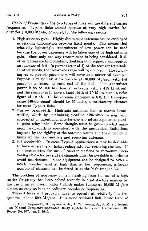
SEC. 7.11] RADAR RELAY 261
Cti oj Freq-.—The two types of links will use different carrierfrequencies. Type-A links should operate at very high carrier fre-quencies (10,000 Me/see or more), for the following reasons:
1. High antenna gain. Highly directional antennas can be employedin relaying information between fixed points. This means thatrelatively light weight transmitters of low power can be usedbecause the power deficiency will be taken care of by high antennagain. Since only one-way transmission is being considered, if allother factors are held constant, doubling the frequency will result inan increase of 6 db (a power factor of 4) at the receiver terminals.In other words, the free-space range will be doubled. The follow-ing set of possible parameters will serve as a numerical example.Suppose a relay link is to operate at 10,000 Me/see. with 4ftparabolic antennas at each end of the link. The transmitterpower is to be 100 mw (easily realizable with a 419 klystron),and the receiver is to have a bandwidth of 10 Me/see and a noisefigure of 12 db. If the antenna efficiency is 0.6, the free-spacerange (40-db signal) should be 55 miles, a satisfactory distancefor most Type-A links.
2. Narrow beamwidth. High-gain antennas lead to narrow beam-widths, which by minimizing possible difficulties arising fromaccidental or intentional interference are advantageous in point-to-point relay links. Some thought must be given to what mini-mum beamwidth is consistent with the mechanical limitationsimposed by the rigidity of the antenna towers and the difficulty oflining up the transmitting and receiving antennas.
3. R-f bandwidth. In some Type-A applications it may be desirableto have several relay links feeding into one receiving station. Ifthis necessitates the use of booster stations to surmount inter-vening obstacles, several r-f channels must be available in order toavoid interference. Since equipment can be designed to cover amuch broader band at high than at low frequencies, a largernumber of channels can be fitted in at the high frequencies.
The problem of frequency control resulting from the use of a highcarrier frequency has been solved recently in a satisfactory manner bythe use of an r-f discriminator,’ which makes tuning at 10,000 Me/seealmost as easy as it is at ordinary broadcast frequencies.
Type-B links will probably have to operate at relatively low fre-quencies, about 500 Me/see. In a nondirectional link, brute force of
1L. M. Hollingsworth, H. Logemarm, Jr., A. W. Lawson, Jr., J. M. Sturtevant,“An X-band Frequency-modulated Relay System for Video Frequencies,” RLReport No. 977, Jan. 3, 1946.
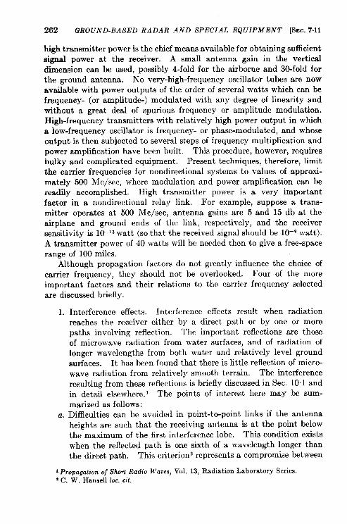
262 GROUND-BASED RADAR AND SPECIAL EQUIPMENT [SEC. 7.11
high transmitter power is the chief means available for obtaining sufficientsignal power at the receiver. A small antenna gain in the verticaldimension can be used, possibly 4-fold for the airborne and 30-fold forthe ground antenna. No very-high-frequency oscillator tubes are nowavailable with power outputs of the order of several watts which can befrequency- (or amplitude-) modulated with any degree of linearity andwithcut a great deal of spurious frequency or amplitude modulation.High-frequency transmitters with relatively high power output in whicha low-frequency oscillator is frequency- or phase-modulated, and whoseoutput is then subjected to several steps of frequency multiplication andpower amplification have been built. This procedure, however, requiresbulky and complicated equipment. Present techniques, therefore, limitthe carrier frequencies for nondirectional systems to values of approxi-mate y 500 M c/see, where modulation and power amplification can bereadily accomplished. High transmitter power is a very importantfactor in a nondirectional relay link. For example, suppose a trans-mitter operates at 500 Me/see, antenna gains are 5 and 15 db at theairplane and ground ends of the link, respectively, and the receiversenaitivit y is 1(Y13watt (so that the received signal should be 10–9 watt).A transmitter power of 40 watts will be needed then to give a free-spacerange of 100 miles.
Although propagation factors do not greatly influence the choice ofcarrier frequency, they should not be overlooked. Four of the moreimportant factors and their relations to the carrier frequency selectedare discussed briefly.
1. Interference effects. Interference effects result when radiation
reaches the receiver either by a direct path or by one or morepaths involving reflection. The important reflections are those
of microwave radiation from water surfaces, and of radiation oflonger wavelengths from both water and relatively level ground
surfaces. It has been found that there is little reflection of micro-
wave radiation from relatively smooth terrain. The interference
resulting from these reflections is briefly discussed in Sec. 10.1 and
in detail elsewhere. 1 The points of interest here may be sum-
mari zed as follows:
a. Difficulties can be avoided in point-to-point links if the antennaheights are such that the receiving antenna is at the point belowthe maximum of the first interference lobe. This condition existswhen the reflected path is one sixth of a wavelength longer thanthe direct path. This criterion represents a compromise between
1Propa@ion of Short Radio Waves, Vol. 13, Radiation Laboratory Series2 C. W, Hansen 10C.cit.
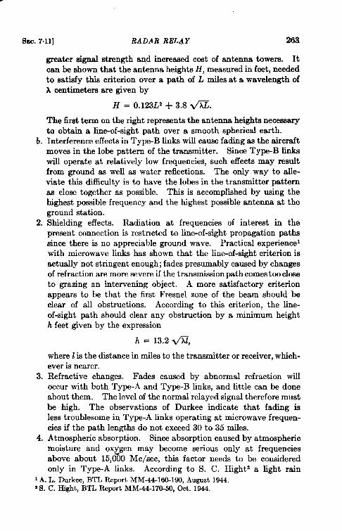
EhEc.7.11] RADAR RELAY 203
greater signal strength aqd increased cost of antenna towers. Itcan be shown that the antenna heights H, measured in feet, neededto satisfy this criterion over a path of L miles at a wavelength ofh centimeters are given by
H = 0.123L’ + 3.8 ~.
The first term on the right represents the antenna heights necessaryto obtain a lin~of-sight path over a smooth spherical earth.
b. Interference effects in Type-B links will cause fading as the aircraftmoves in the lobe pattern of the transmitter. Since Type-B linkswill operate at relatively low frequencies, such effects may resultfrom ground as well as water reflections. The only way to alle-viate this difficulty is to have the lobes in the transmitter patternaa close together as possible. This is accomplished by using thehighest possible frequency and the highest possible antenna at theground station.
2. Shielding effects. Radiation at frequencies of interest in thepresent connection is restricted to line-of-sight propagation pathssince there is no appreciable ground wave. Practical experiencewith microwave links has shown that the line-of-sight criterion isactually not stringent enough; fades presumably caused by changesof refraction are more severe if the transmission path comes too closeto grazing an intervening object. A more satisfactory criterionappears to be that the first Fresnel zone of the beam should beclear of all obstructions. According to this criterion, the line-of-sight path should clear any obstruction by a minimum heighth feet given by the expression
h = 13.2@,
where I?is the distance in miles to the transmitter or receiver, which-ever is nearer.
3. Refractive changes. Fades caused by abnormal refraction willoccur with both Type-A and Type-B links, and little can be doneabout them. The level of the normal relayed signal therefore mustbe high. The observations of Durkee indicate that fading isless troublesome in Type-A links operating at microwave frequen-cies if the path lengths do not exceed 30 to 35 miles.
4. Atmospheric absorption. Since absorption caused by atmosphericmoisture and oxygen may become serious only at frequenciesabove about 15,660 Me/see, this factor needs to be consideredonly in Type-A links. According to S. C. Hight’ a light rain
i A. L. Durkee, BTL Report MM-44-160-190, August 1944.z S. C. Hight, BTL Report MM-44-170-50, Oct. 1944.
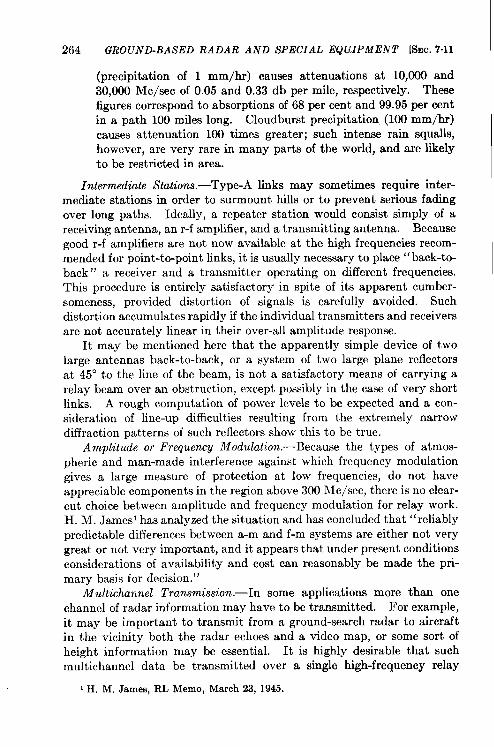
264 GROUND-BASED RADAR AND SPECIAL EQUIPMENT [S!IC. 7.11
(precipitation of 1 mm/hr) causes attenuations at 10,000 and30,000 Me/see of 0.05 and 0.33 db per mile, respectively. Thesefigures correspond to absorption of 68 per cent and 99.95 per centin a path 100 miles long. Cloudburst precipitation (100 mm/hr)causes attenuation 100 times greater; such intense rain squalls,however, are very rare in many parts of the world, and are likelyto be restricted in area.
Intermediate Stations.-Type-A links may sometimes require inter-mediate stations in order to surmount hills or to prevent serious fadingover long paths. Ideally, a repeater station would consist simply of areceiving antenna, an r-f amplifier, and a transmitting antenna. Becausegood r-f amplifiers are not now available at the high frequencies recom-mended for point-to-point links, it is usually necessary to place “back-to-back” a receiver and a transmitter operating on different frequencies.This procedure is entirely satisfactory in spite of its apparent cumber-someness, provided distortion of signals is carefully avoided. Suchdistortion accumulates rapidly if the individual transmitters and receiversare not accurately linear in their over-all amplitude response.
It may be mentioned here that the apparently simple device of twolarge antennas back-to-back, or a system of two large plane reflectorsat 45° to the line of the beam, is not a satisfactory means of carrying arelay beam over an obstruction, except possibly in the case of very shortlinks. A rough computation of power levels to be expected and a con-sideration of line-up difficulties resulting from the extremely narrowdiffraction patterns of such reflectors show this to be true.
Amplitude or Frequency Modulation. —Because the types of atmos-pheric and man-made interference against which frequency modulationgives a large measure of protection at low frequencies, do not haveappreciable components in the region above 300 Me/see, there is no clear-cut choice between amplitude and frequency modulation for relay work.H. M. James’ has analyzed the situation and has concluded that “ reliablypredictable differences between a-m and f-m systems are either not verygreat or not very important, and it appears that under present conditionsconsiderations of availability and cost can reasonably be made the pri-mary basis for decision. ”
Multichannel Transmission.—In some applications more than onechannel of radar information may have to be transmitted. For example,it may be important to transmit from a ground-search radar to aircraftin the vicinity both the radar echoes and a video map, or some sort ofheight information may be essential. It is highly desirable that suchmultichannel data be transmitted over a single high-frequency relay
I H. M. .James, RL Memo, March 23, 1945.
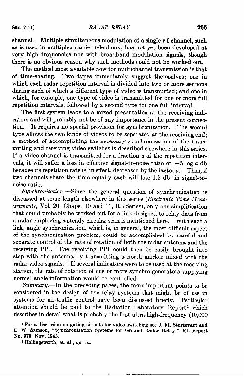
SEC.7.11] RADAR RELAY 265
channel. Multiple simultaneous modulation of a single r-f channel, suchaa is used in multiplex carrier telephony, has not yet been developed atvery high frequencies nor with broadband modulation signals, thoughthere is no obvious reason why such methods could not be worked out.
The method most available now for multichannel transmission is thatof time-sharing. Two types immediately suggest themselves; one inwhich each radar repetition interval is divided into two or more sectionsduring each of which a different type of video is transmitted; and one inwhich, for example, one type of video is transmitted for one or more fullrepetition intervals, followed by a second type for one full interval.
The first system leads to a mixed presentation at the receiving indi-—caters and will probably not be of any importance in the present connec-tion. It requires no special provision for synchronization. The secondhype allows the two kinds of videos to be separated at the receiving end;a method of accomplishing the necessary synchronization of the trans-mitting and receiving video switches is described elsewhere in this series.If a video channel is transmitted for a fraction a of the repetition inter-vals, it will suffer a loss in effective signal-to-noise ratio of – 5 log a dbbecause its repetition rate is, iri effect, decreased by the factor a. Thus, iftwo channels share the time equally each will lose 1.5 dbl in signal-to-noise ratio.
Synchronization. -Since the general question of synchronization isdiscussed at some length elsewhere in this series (Electronic Time Meas-
urements, Vol. 20, Chaps. 10 and 11, RL Series), only one simplificationthat could probably be worked out for a link designed to relay data froma radar employing a steady circular scan is mentioned here. With such alink, angle synchronization, which is, in general, the most difficult aspectof the synchronization problem, could be accomplished by careful andseparate control of the rate of rotation of both the radar antenna and thereceiving PPI. The receiving PPI could then be easily brought intostep with the antenna by transmitting a north marker mixed with theradar video signals. If several indicators were to be used at the receivingstation, the rate of rotation of one or more synchro generators supplyingnormal angle information would be controlled.
Summury.-In the preceding pages, the more important points to beconsidered in the design of the relay systems that might be of use insystems for air-traffic control have been discussed briefly. Particularattention should be paid to the Radiation Laboratory Report2 whichdescribes in detail what is probably the first ultra-high-frequency (10,000
1For a discussion on gating circuits for video switching see J. M. Sturtevant andE. W. Samson, “Synchronization Systems for Ground Radar Relay,” RL ReportNo. 978, NOV. 1945.
* Hollingsworth, et. al., op. cd.
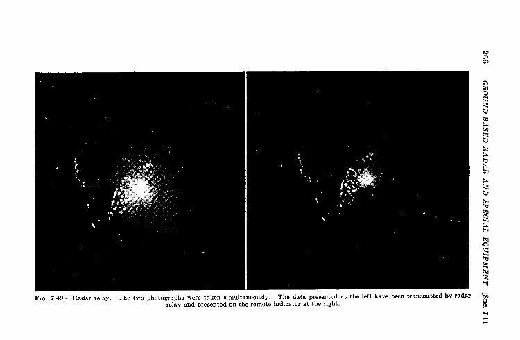
266G
RO
UN
D-B
ASE
DR
AD
AR
AN
DSP
EC
IAL
EQ
UIP
ME
NT
[SE
C.
7.11
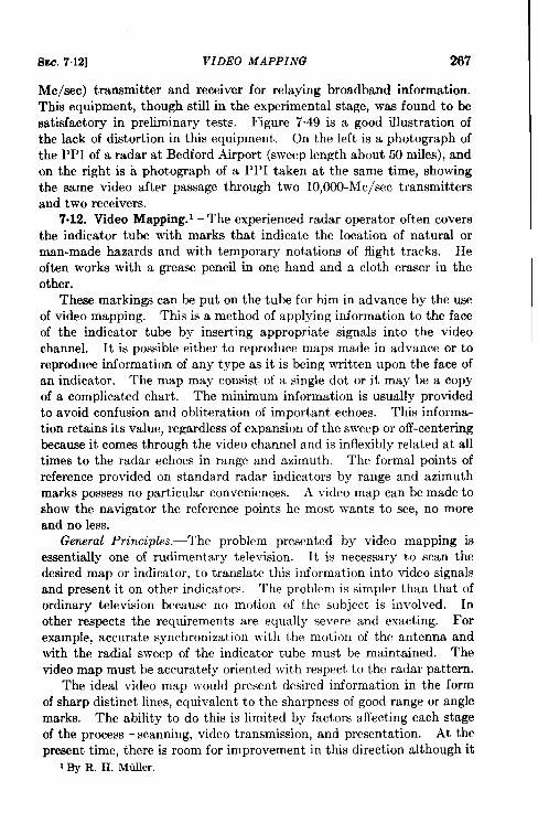
SEC. 7.12] VIDEO MAPPING 267
Me/see) transmitter and receiver for relaying broadband information.This equipment, though still in the experimental stage, was found to ksatisfactory in preliminary tests. Figure 7.49 is a good illustration ofthe lack of distortion in this equipment. On the left is a photograph ofthe PPI of a radar at Bedford Airport (sweep length about 50 miles), andon the right is a photograph of a PPI taken at the same time, showingthe same video after passage through two 10,000-Mc/sec transmittersand two receivers.
7.12. Video Mapping. ‘The experienced radar operator often coversthe indicator tube with marks that indicate the location of natural orman-made hazards and with temporary notations of flight tracks. Heoften works with a grease pencil in one hand and a cloth eraser in theother.
These markings can be put on the tube for him in advance by the useof video mapping. This is a method of applying information to the faceof the indicator tube by inserting appropriate signals into the videochannel. It is possible either to reproduce maps made in advance or toreproduce information of any type as it is being written upon the face ofan indicator. The map may consist of a single dot or it may be a copyof a complicated chart. The minimum information is usually providedto avoid confusion and obliteration of important echoes. This informa-tion retains its value, regardless of expansion of the sweep or off-centeringbecause it comes through the video channel and is inflexibly related at alltimes to the radar echoes in range and azimuth. The formal points ofreference provided on standard radar indicators by range and azimuthmarks possess no particular conveniences. A video map can be made toshow the navigator the reference points he most wants to see, no moreand no less.
General Principles.-The problem presented by video mapping isessentially one of rudimentary television. It is necessary to scan thedesired map or indicator, to translate this information into video signalsand present it on other indicators. The problcm is simpler than that ofordinary television because no motion of the subject is involved. Inother respects the requirements are equally severe and exacting. Forexample, accurate synchronization with the motion of the antenna andwith the radial sweep of the indicator tube must be maintained. Thevideo map must be accurately oriented with respect to the radar pattern.
The ideal video map would present desired information in the formof sharp distinct lines, equivalent to the sharpness of good range or anglemarks. The ability to do this is limited by factors affecting each stageof the process—scanning, video transmission, and presentation. At thepresent time, there is room for improvement in this direction although it
I By R. H. Miiller.
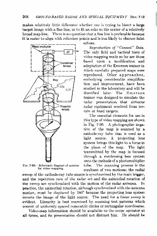
268 GROUND-BASED RADAR AND SPECIAL EQUIPMENT [SEC. 7.12
makes relatively little difference whether one is trying to bisect a largetarget image with a fine line, or to fit an echo to the center of a relativelybroad map line. There is no question that a fine line is preferable becauseit is easier to align with reference points and is lees likely to obscure faint
FIQ. 7.50.—Schematic diagram of scannerfor video mapping.
echoes.Reproduction of “Canned” Data.
The only field and tactical tests of
video mapping made so far are those
based upon a modification and
adaptation of the Emerson trainer inwhich carefully prepared maps were
reproduced. Other approach es,
embodying considerable simplifica-
tion and improvement, have been
studied in the laboratory and will be
described later. The E m e rs o n
trainer was designed to simulate the
radar presentation that airborne
radar equipment received from ter-
rain or fixed targets.
The essential elements for use in
this type of video mapping are shown
in Fig. 7.50. A photographic nega-
tive of the map is scanned by a
cathode-ray tube that is used as a
light source. A projecting lens
system brings this light to a focus inthe plane of the map. The lighttransmitted by the map is focusedthrough a condensing lens systemonto the cathode of a photomultipliertube. The scanning process is theresultant of two motions; the radial
sweep of the cathode-ray tube source is synchronized by the main trigger,and the repetition rate of the radar set and the azimuthal rotation ofthe sweep are synchronized with the motion of the radar antenna. Inpractice, the azimuthal rotation, although synchronized with the antennamotion, must be displaced by 180° because the projecting lens systeminverts the image of the light source. The need for a linear sweep isevident. Linearity is best examined by scanning test patterns whichconsist of uniformly spaced concentric circles or rectangular coordinates.
Video-map information should be available to the scope operator atall times, and its presentation should not distract him. He should be
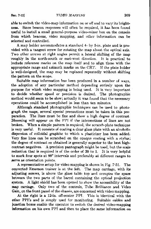
Sm. 7.12] VIDEO MAPPING 269
able to switch the video-map information on or off and to vary its bright-ness. Since beacon responses will often be required, it has been founduseful to install a small general-purpose video-mixer box on the consolefrom which beacons, video mapping, and other information can beselected and controlled.
A map holder accommodates a standard 4- by 5-in. plate and is pro-vided with a tangent screw for rotating the map about the optical axis.Two other screws at right angles permit a lateral shifting of the maproughly in the north-south or east-west direction. It k practical toinclude reference marks on the map itself and to align these with theappropriate range and azimuth marks on the CRT. If the plate holderis well-designed, the map may be replaced repeatedly without shiftingthe pattern on the scope.
Suitable map information has been produced in a number of ways,the adoption of any particular method depending entirely upon thepurpose for which video mapping is being used. It is very importantto decide whether speed or precision is desired. The photographicmethod would seem to be slow; actually it was found that the necessaryoperations could be accomplished in less than ten minutes.
Although standard photographic techniques can be used to photo-graph the maps, several special precautions must be taken in this prepsration. The lines must be fine and show a high degree of contrastBlooming will appear on the PPI if the intersections of lines are notbroken. When a simple pattern is required, the scratch-plate techniqueis very useful. It consists of coating a clear glass plate with an alcoholicdispersion of colloidal graphite to which a plasticizer has been added:Very fine lines can be scrstched on the opaque coating with a stylus;the degree of contrast so obtained is generally superior to the best high-contrsst negatives. A precision pantograph might be used, but the scalereduction that is required is of the order of Xl to 1. It is very helpfulto mark four spots at 90° intervals and preferably at different ranges toserve as orientation points.
A representative setup for video mapping is shown in Fig. 7.51. Theconverted Emerson trainer is at the left. The map carriage, with itsadjusting screws, is above the glass table top and occupies the spacebetween the two parts of the barrel containing the optical projectionsystem. A light shield has been opened to show the accessibility of themap carriage. Only two of the controls, Tube Brilliance and VideoGain, on the front panel of the chassis, are concerned with video mapping.
At the right is a 12-in. off-center PPI. This is identical with theother PPI’s and is simply used for monitoring. Suitable cables andjunction boxes enable the operator to switch the desired video-mappinginformation on his own PPI and then to place the same information on
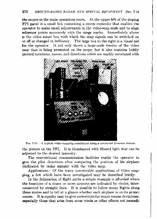
2’70 GROUND-BASED RADAR AND SPECIAL EQUIPMENT [SEC. 7.12
the scopes in the main operations room. At the upper left of the slopingPPI panel is a small box containing a sweep expander that enables theoperator to make small adjustments in the video-map scale and to alignreference points accurately with the range marks. Immediately aboveis the video mixer box with which the map signals can be switched onor off or changed in brilliancy. The large box to the right is a visual aidfor the operator. It not only shows a large-scale version of the videomap that is being presented on the scope, but it also contains boldlyprinted notations, names, and directions which are readily correlated with
FIII. 7.51 .—A typical video-mapping installation using a converted Emerson trainer.
the picture on the PPI. It is illuminated with filtered light that can beadjusted to the desired intensity.
The conventional communication facilities enable the operator togive the pilot directions after comparing the position of hk airplane(indicated by radar signals) with the video map.
Applications.—Of the many conceivable applications of video map-ping, a few which have been investigated may be described briefly.
In the delineation of flight paths a simple example is afforded wherethe locations of a dozen or more airports are indicated by circles, inter-connected by straight lines. It is possible to follow many flights alongthese routes and to tell at a glance whether each airplane is on its propercourse. It is equally easy to give corrections for minor course deviations,especially those that arise from cross winds or other effects not immedi-
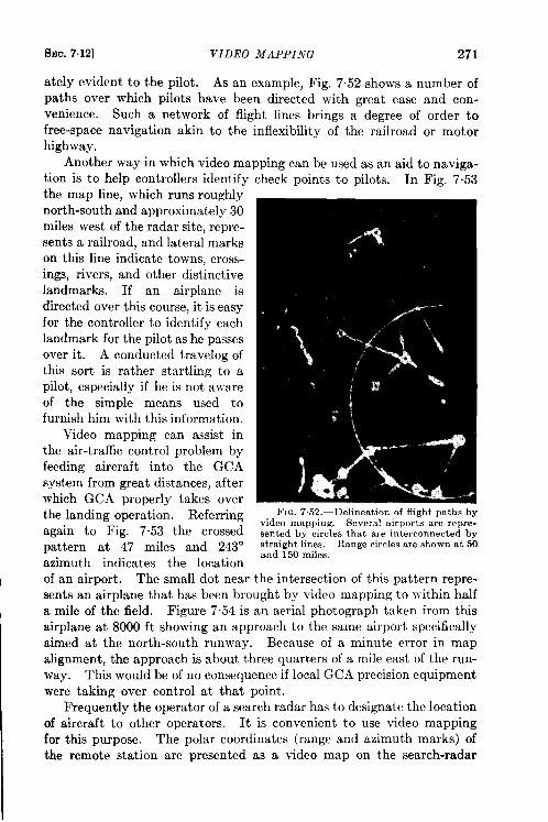
SEC. 7.12] VIDEO MAPPING 271
ately evident to the pilot. As an example, Fig. 752 shows a number ofpaths over which pilots have been directed with great ease and con-venience. Such a network of flight lines brings a degree of order tofree-space navigation akin to the inflexibility of the railroad or motorhighway.
Another way in which video mapping can be used as an aid to naviga-tion is to help controllers identify check points to pilots. In Fig. 7.53
the map line, which runs roughly
north-south and approximately 30
miles west of the radar site, repre-
sents a railroad, and lateral marks
on this line indicate towns, cross-
ings, rivers, and other distinctive
landmarks. If an airplane is
directed over this course, it is easy
for thecontroller to identify each
landmark for the pilot as he passes
over it. A conducted travelog of
this sort is rather startling to a
pilot, especially if he is not aware
of the simple means used tofurnish him with this information.
Video mapping can assist in
the air-traffic control problem by
feeding aircraft into the GCA
system from great distances, after
which GCA properly takes over
the landing operation. Referring
again to Fig. 7.53 the crossed
pattern at 47 miles and 243°azimuth indicates the location
of an airport. The small dot near
sents an airplane that has been brought by video mapping to within half
a mile of the field. Figure 7.54 is an aerial photograph taken from this
airplane at 8000 ft showing an approach to the same airport specifically
aimed at the north-south runway. Because of a minute error in map
alignment, the approach is about three quarters of a mile east of the run-
way. This would be of no consequence if local GCA precision equipment
were taking over control at that point.
Frequently the operator of a search radar has to designate the location
of aircraft to other operators. It is convenient to use video mapping
for this purpose. The polar coordinates (range and azimuth marks) of
the remote station are presented as a video map on the search-radar
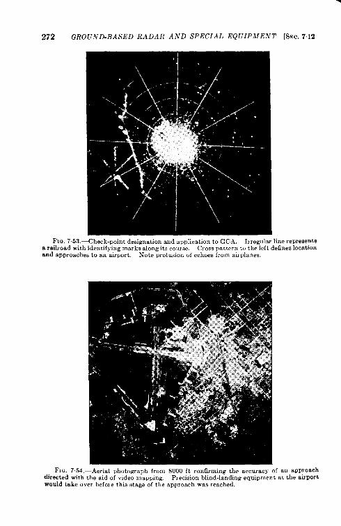
272 GROUND-BASED RADAR AND SPECIAL EQUIPMENT [SEC. 712
FIG.. 7.53,—Check-point designation and application to GCA, Irregular line representsa railroad with identifying marks along its course. Cross pattern to the left defines locationand approaches to an airport. Note profusion of echoes from airplanes,
FI~. 7.54.—Aerial photo=aph from S000 ft confirming the accuracy of an approachdirected with the aid of video ~rlaPPing, precision blind-landing ~quiPment at the airportwould take over before this stage of the approach was reached,

SEC. 7.12] VIDEO MAPPING 273
indicator. Airplane echoes are now reported to the remote stationdirectly in terms of its own PPI coordinates. Tests have shown thatthis method saves much time, especially with rapidly moving aircraft.
Prm”sion.-The present limitations in producing fine lines by thkmethod are best evaluated by reference to Fig. 7-55. A point 70 milesfrom the radar site has been designated by the intersection of two straight
FIG. 7.55.—Designation of point by intersection of two straight lines, 70-mile range withoff-centered presentation.
lines. This appears on the scope, with an off-centering of about 1.5radii and the most distant end terminating at a thunderhead. The echofrom a four-engine airplane is approaching the intersection along a desig-nated heading of about 304”. Since the echo itself is relatively broadthere is no particular handicap in the considerable width of the video-mm line.
‘Figures 7.56a and 7.56fI show a more complex pattern, also at a rangeof 70 miles In Fig. 7.56a an airplane is approaching the intersection
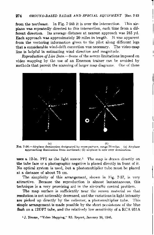
274 GROUND-BASED RADAR AND SPECIAL EQUIPMENT [SEC. 7.12
from the northeast. In Fig. 7.56b it is over the intersection. This air-plane was repeatedly directed to this intersection, each time from a dif-ferent direction. Its average distance at nearest approach was 245 yd.Each approach was approximately 20 miles in length. It was apparentfrom the vectoring information given to the pilot along different legsthat a considerable wind-drift correction was necessary. The video-mapline is helpful in estimating wind direction and magnitude.
Reproduction oj Live Data. —Some of the severe limitations imposed onvideo mapping by the use of an Emerson trainer can be avoided bymethods that permit the scanning of larger map diagrams. One of these
1
I
(“) (h).—,Fm. 7.56.—Airplane destination designated by cross pattern, range 70 miles. (a) Airplane
.. ,
apprOac~ng destination from northeast; (b) airplane is now over destination.
uses a 12-in. PPI as the light source. 1 The map is drawn directly onthe tube face or a photographic negative is placed directly in front of it.No optical system is used, but a photomultiplier tube must be placedat a dktance of about 75 cm.
The simplicity of this arrangement, shown in Fig. 7.57, is veryattractive. Because the reproduction is almost instantaneous, thistechnique is a very promising aid in the air-traffic control problem.
The map surface is sufficiently near the screen material so thatresolution is not noticeably decreased, and the variations in light intensityare picked up directly by the collector, a phot omultiplier tube. Thissimple arrangement is made possible by the short persistence of the blueflash on a 12DP7 tube, and the relatively low sensitivity of a RCA 931A
‘J. Hexem, “Video Mapping,” RL Report, January26, 1946.
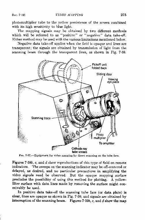
SEC, 712] VIDEO MAPPING 275
photomultiplier tube to the yellow persistence of the screen combinedwith its high sensitivity to blue light.
The mapping signals may be obtained by two different methodswhich will be referred to as “positive” or “negative” data take-off.Either method may be used with the various limitations mentioned below.
Negative data take-off applies when the field is opaque and lines aretransparent; the signals are obtained by transmission of light from thescanning beam through the transparent lines, as shown in Fig. 7.58.
; .....ZcathJderay To arn’plifier
tubescreenFIG. 7.57.—Equipment for video mapping by direct scanning on the tube face.
F@res 7.58b, c, and d show reproductions of this type of field on remoteindicators. The sweeps on the scanning indicator may be off-centered ordelayed, as desired, and no particular ~recautions in am&fvin~ thevideo signals need be observed. But ‘the opaque mapping” s~rfaceprecludes the possibility of using this method for plotting. A yellow-filter surface with data lines made by removing the surface might con-ceivably be used.
In positive data take-off the scanning tube face (or data plate) isclear, lines are opaque as shown in Fig. 7.59, and signals are obtained byinterruption of the scanning beam. Figures 7“59b, c, and d show the map
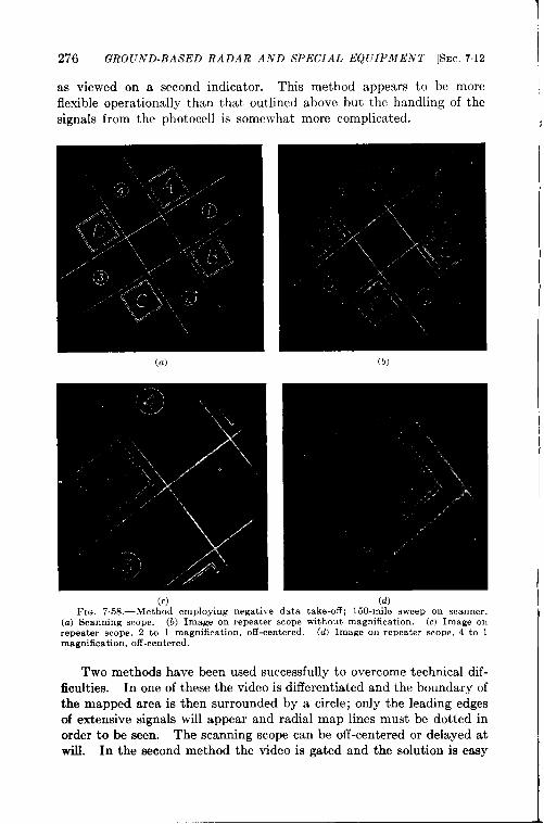
276 GRO(JND-BASED RA DAR AND SPECIAL EQUIPMENT [SEC. 712
as viewed on a second indicator. This method appears to be moreflexible operationally than that outlined above but the handling of thesignals from the photocell is somewhat more complicated.
(b)
f
(c) (d)FIG. 7.58.—Method employing negative data take-off; 150-mile sweep on scanner.
(a) Scanning scope. (b) Image on repeater scope without magnification. (c) Image onrepeater scope, 2 to 1 magnification, off-centered. (d) Image on repeater scope, 4 to 1magnification, off-centered.
Two methods have been used successfully to overcome technical dif-ficulties. In one of these the video is differentiated and the boundary ofthe mapped area is then surrounded by a circle; only the leading edgesof extensive signals will appear and radial map lines must be dotted inorder to be seen. The scanning scope can be off-centered or delayed atwill. In the second method the video is gated and the solution is easy
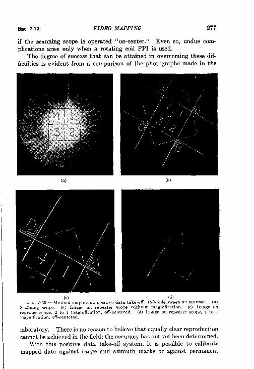
SEQ. 7,12] VIDEO MAPPING 277
if the Bcmming scope is operated “on-center.” Even so, undue com-plications arise only when a rotating coil PPI is used.
The degree of success that can be attained in overcoming these dif-ficulties is evident from a comparison of the photographs made in the
(a)
(c).-,FIG. 7.59- Method emnlovine Dositive data take+ff: 150-mile sween on scanner. (a)
.,.. –.-.
Scanning scope. (b) Image on repeater scope without magmficatio-n. (c) Image onrepeater scope, 2 to I magnification, off-centered. (d) Image on repeater scope, 4 to 1magnification, off-centered.
laboratory. There is no reason to believe that equally clear reproduction
cannot be achieved in the field; the accuracy has not yet been determined.
With this positive data take-off system, it is possible to calibrate
mapped data against range and azimuth marks or against permanent
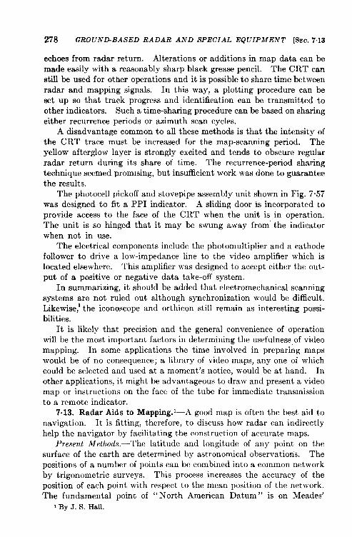
278 GROUND-BASED RADAR AND SPECIAL EQUIPMENT [SEC. 7.13
echoes from radar return. Alterations or additions in map data can bemade easily with a reasonably sharp black grease pencil. The CRT canstill be used for other operations and it is possible to share time betweenradar and mapping signals. In this way, a plotting procedure can beset up so that track progress and identification can be transmitted toother indicators. Such a time-sharing procedure can be based on sharingeither recurrence periods or azimuth scan cycles.
A disadvantage common to all these methods is that the intensity ofthe CRT trace must be increased for the map-scanning period. Theyellow afterglow layer is strongly excited and tends to obscure regularradar return during its share of time. The recurrence-period sharingtechnique seemed promising, but insufficient work was done to guaranteethe results.
The photocell pickoff and stovepipe assembly unit shown in Fig. 7.57was designed to fit a PPI indicator. A sliding door is incorporated toprovide access to the face of the CRT when the unit is in operation.The unit is so hinged that it may be swung away from” the indicatorwhen not in use.
The electrical components include the photomultiplier and a cathodefollower to drive a low-impedance line to the video amplifier which islocated elsewhere. This amplifier was designed to accept either the out-put of a positive or negative data take-off system.
In summarizing, it should be added that electromechanical scanningsystems are not ruled out although synchronization would be difficult.Likewise,’ the iconoscope and orthicon still remain as interesting possi-bilities.
It is likely that precision and the general convenience of operationwill be the most important factors in determining the usefulness of videomapping. In some applications the time involved in preparing mapswould be of no consequence; a library of video maps, any one of whichcould be selected and used at a moment’s notice, would be at hand. Inother applications, it might be advantageous to draw and present a videomap or instructions on the face of the tube for immediate transmissionto a remote indicator.
7.13. Radar Aids to Mapping.’—A good map is often the best aid tonavigation. It is fitting, therefore, to discuss how radar can indirectlyhelp the navigator by facilitating the construction of accurate maps.
Present Methods.—The latitude and longitude of any point on thesurf ace of the cart h are determined by astronomical observations. Thepositions of a number of points can be combined into a common networkby trigonometric surveys. This process increases the accuracy of theposition of each point with respect to the mean position of the network.The fundamental point of “ North American Datum” is on Meades’
1By J. S. Hall.
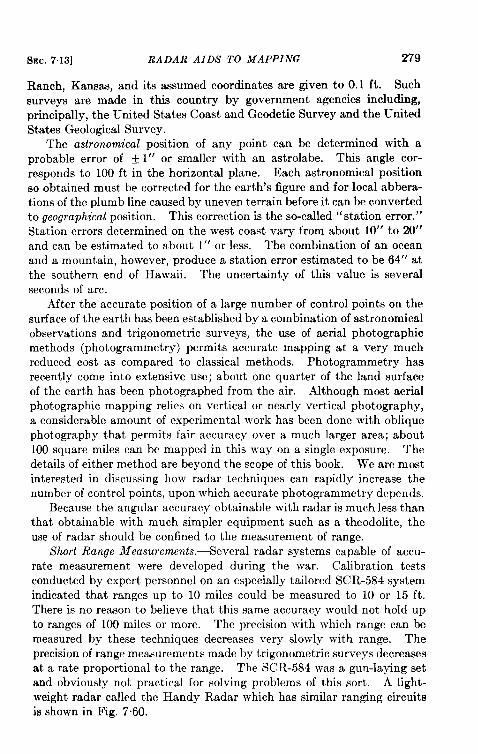
SEC. 7.13] RADAR AIDS TO MAPPING 279
Ranch, Kansas, anditsassumed coordinates aregivento O.1 ft. Suchsurveys are made in this country by government agencies including,principally, the United States Coast and Geodetic Survey and the UnitedStates Geological Survey.
The astronomical position of any point can be determined with aprobable error of f 1“ or smaller with an astrolabe. This angle cor-responds to 100 ft in the horizontal plane. Each astronomical positionso obtained must be corrected for the earth’s figure and for local abbera-tions of the plumb line caused by uneven terrain before it can be convertedto geographical position. This correction is the so-called “station error. ”Station errors determined on the west coast vary from about 10” to 20”and can be estimated to about 1“ or less. The combination of an oceanand a mountain, however, produce a station error estimated to be 64” atthe southern end of Hawaii. The uncertainty of this value is severalseconds of arc.
After the accurate position of a large number of control points on thesurface of the earth has been established by a combination of astronomicalobservations and trigonometric surveys, the use of aerial photographicmethods (photogrammetry) permits accurate mapping at a very muchreduced cost as compared to classical methods. Photogrammetry hasrecently come into extensive use; about one quarter of the land surfaceof the earth has been photographed from the air. Although most aerialphotographic mapping relies on vertical or nearly vertical photography,a considerable amount of experimental work has been done with obliquephotography that permits fair accuracy over a much larger area; about100 square miles can be mapped in this way on a single exposure. Thedetails of either method are beyond the scope of this book. We are mostinterested in discussing how radar techniques can rapidly increase thenumber of control points, upon which accurate photogrammetry depends.
Because the angular accuracy obtainable with radar is much less thanthat obtainable with much simpler equipment such as a theodolite, theuse of radar should be confined to the measurement of range.
Short Range Measurements. —Several radar systems capable of accu-rate measurement were developed during the war. Calibration testsconducted by expert personnel on an especially tailored SCR-584 systemindicated that ranges up to 10 miles could be measured to 10 or 15 ft.There is no reason to believe that this same accuracy would not hold upto ranges of 100 miles or more. The precision with which range can bemeasured by these techniques decreases very slowly with range. Theprecision of range measurements made by trigonometric surveys decreasesat a rate proportional to the range. The SCR-584 was a gun-laying setand obviously not practical for solving problems of this sort. A light-weight radar called the Handy Radar which has similar ranging circuitsis shown in Fig. 7.60.
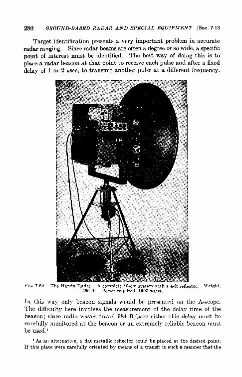
280 GROUND-BASED RADAR AND SPECIAL EQUIPMENT [SEC. 7.13
Target identification presents a very important problem in accurateradar ranging. Since radar beams are often a degree or so wide, a specificpoint of interest must be identified. The best way of doing this is toplace a radar beacon at that point to receive each pulse and after a fixeddelay of 1 or 2 Ysec, to transmit another pulse at a different frequency.
FIG. 760.- -T‘he Handy Radar. A complete 10-cm system with a 4-ft refle,250 lb. Power required, 1500 watts.
:tor. ;ight,
In this way only beacon signals would be presented on the A-scope.The difficulty here involves the measurement of the delay time of thebeacon; since radio waves travel 984 ft/psec either this delay must becarefully monitored at the beacon or an extremely reliable beacon mustbe used.’
1 As an alternative, a flat metallic reflector could be placed at, the desired point.If this plate were carefully oriented by means of a transit in such a manner that the
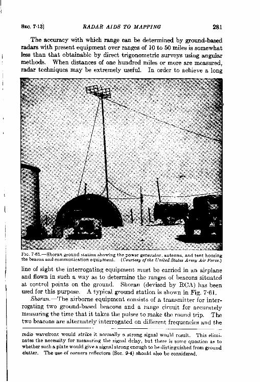
SEC. 7.13] RADAR AIDS TO MAPPING 281
The accuracy with which range can be determined by ground-basedradars with present equipment over ranges of 10 to 50 miles is somewhatless than that obtainable by direct trigonometric surveys using angularmethods. When distances of one hundred miles or more are measured,radar techniques may be extremely useful. In order to achieve a long
FIG. 7.61. —Shoran ground station showing the power generator, antenna, and tent housingthe beacon and communication equipment. (Courtesp of the United State-sArmg Air Force,)
line of sight the interrogating equipment must be carried in an airplaneand flown in such a way as to determine the ranges of beacons situatedat control points on the ground. Shoran (devised by RCA) has beenused for this purpose. A typical ground station is shown in Fig. 7.61.
Shoran.—The airborne equipment consists of a transmitter for inter-rogating two ground-based beacons and a range circuit for accuratelymeasuring the time that it takes the pulses to make the round trip. Thetwo beacons are alternately interrogated on different frequencies and the
radiowavefrontwould strike it normally a strong signalwould result. This elimi-natesthe necessityfor measuringthe signal delay, but there is some questionas towhethersucha platewouldgivea signalstrongenoughto be distinguishedfromgroundclutter. The use of cornersreflectors(Sec. 9.4) shouldalso be considered.
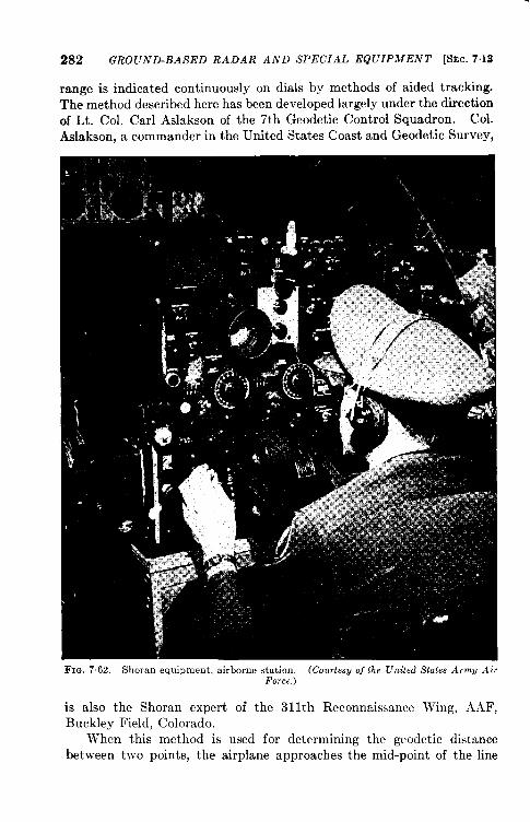
282 GROUND-BASED RA DAR AND SPECIAL EQUIPMENT
range is indicated continuously on dials by methods of aided
[SEC. 7.13
tracking.
The method described here has been developed largely under the directionof Lt. Col. Carl Aslakson of the 7th Geodetic Control Squadron. Col.
Aslakson, a commander in the United States Coast and Geodetic Survey,
FIG. 7.62. —Sboran equipment, airborne station, (Courtes~ of the United SM.. Arm~ AirForce.)
is also the Shoran expert of the 31 Ith Reconnaissance Wing, .4AF,Buckley Field, Colorado.
When this method is used for determining the geodetic distancebetween two points, the airplane approaches the mid-point of the line
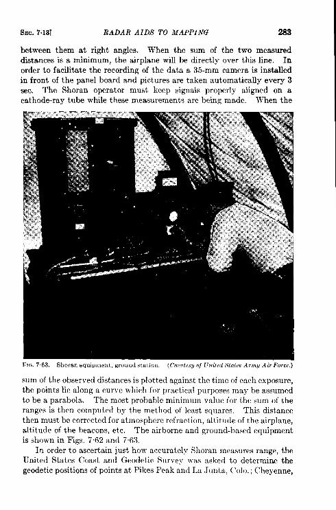
f!.Ec.7.13] RADAR AIDS TO MAPPING 283
between them at right angles. When the sum of the two measureddktances is a minimum, the airplane will be directly over this line. Inorder to facilitate the recording of the data a 35-mm camera is installedin front of the panel board and pictures are taken automatically every 3sec. The Shoran operator must keep signals properly aligned on acathode-ray tube while these measurements are being made. When the
FIO. 7.63. —Shoran equipment, ground station, (C.,o+esu of United States Army Air Force.)
sum of the observed distances is plotted against the time of each exposure,the points lie along a curve which for practical purposes may be assumedto be a parabola. The most probable minimum vallle for the sum of theranges is then computed by the method of least squares. This distancethen must be corrected for atmosphere refraction, altitude of the airplane,altitude of the beacons, etc. The airborne and ground-based equipmentis shown in Figs. 7.62 and 7.63.
In order to ascertain just how accurately Shoran measures range, theIJnited States Coast and Geodetic Survey v-as asked to determine thegeodetic positi~ns of points at Pikes Peak and La Junta, C’olo.; Cheyenne,
284 GROUND-BASED RADAR AND SPECIAL EQUIPMENT [SEC. 7.13
Wyo.; Imperial, Neb.; and Garden City, Kan. Ground stations wereerected at these points and the lines between them were flown many timeswith Shoran-equipped airplanes. The average of all line crossings madein the experimental area with rather crude equipment indicated an errorof 1 ft in 33,000. This compares favorably with the permissible errorof 1 part in 25,000 in first-order control work in geodetic surveys. Theaccuracy coverer! a wide range. For example, the error in the PikesPeak—La Junta line was 1 ft in 6000 (comparable to third-order work)whereas the error in the Cheyenne-Garden City line was only 1 ft in150,000. It is expected that new and improved installations will increasethk accuracy.
The accurate position of a third point may be determined by measur-ing the distance between two known positions and that of the unknownusing similar procedures. If this process were continued, it is estimatedthat a control network for the entire world could be extended from a baseline no longer than Florida. The length of line that can be measured bythe Shoran method depends on the maximum altitude that the airplanecan fly and on the elevation above sea level of the two points involved.Distances between points 400 and 500 miles apart can be directly measured.
The accuracy obtainable by Shoran is of the same order as that withwhich the velocity of light is known. There is no reason to suspect thatthis differs from the velocity of radio waves. Comparison between theresults of angular- and direct-ranging methods of measuring dist ante maylead to a better determination of the velocity of radio waves.
This method appears to be a very promising one for determining posi-tions of numerous control points throughout the world. The spacesbetween these points can then be accurately filled in by photogrammetry.
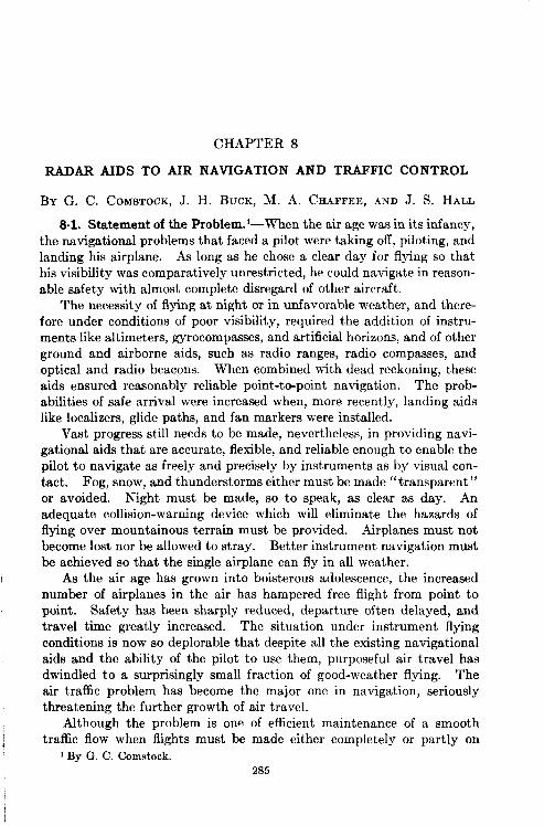
CHAPTER 8
RADAR AIDS TO AIR NAVIGATION AND TIUU?FIC CONTROL
BY G. C. COMSTOCK, J. H. BUCK, M. A. CHAFFEE, AND J. S. HALL
8.1. Statement of the Problem.l-When the air age was in its infancy,the navigational problems that faced a pilot were taking off, piloting, andlanding his airplane. As long as he chose a clear day for flying so thathis visibility was comparatively unrestricted, he could navigate in reason-able safety with almost complete disregard of other aircraft.
The necessity of flying at night or in unfavorable weather, and there-fore under conditions of poor visibility, required the addition of instru-ments like altimeters, gyrocomp~ses, and artificial horizons, and of otherground and airborne aids, such as radio ranges, radio compasses, andoptical and radio beacons. When combined with dead reckoning, theseaids ensured reasonably reliable point-t ~point navigation. The prob-abilities of safe arrival were increased when, more recently, landing aidslike localizes, glide paths, and fan markers were installed.
Vast progress still needs to be made, nevertheless, in providing navi-gational aids that are accurate, flexible, and reliable enough to enable thepilot to navigate as freely and precisely by instruments as by visual con-tact. Fog, snow, and thunderstorms either must be made “transparent”or avoided. Night must be made, so to speak, as clear as day. Anadequate collision-warning device which will eliminate the hazards offlying over mountainous terrain must be provided. Airplanes must notbecome lost nor be allowed to stray. Better instrument navigation mustbe achieved so that the single airplane can fly in all weather.
As the air age has grown into boisterous adolescence, the increasednumber of airplanes in the air has hampered free flight from point topoint. Safety has been sharply reduced, departure often delayed, andtravel time greatly increased. The situation under instrument flyingconditions is now so deplorable that despite all the existing navigationalaids and the ability of the pilot to use them, purposeful air travel hasdwindled to a surprisingly small fraction of good-weather flying. Theair traffic problem has become the major one in navigation, seriouslythreatening the further growth of air travel.
Although the problem is one of efficient maintenance of a smoothtraffic flow when flights must be made either completely or partly on
1By G. C. Comstock.285
286 RADAR IN AIR NAVIGATION AND TRAFFIC CONTROL [SEC. 8.1
instruments, a traffic problem also exists under contact conditions,particularly where traffic is dense, as at an airport.
A completely self-regulatory system does not appear to be feasible.In addition to the traffic rules that are now in force, external traffic-control devices to aid in maintaining a safe and efficient flow and to pro-vide surveillance over possible infringements of the rules must be devised.Because the amount and severity of control needed depends on thedensity of the traffic, the control required in “instrument weather” inthe approach zone surrounding one or several airports is likely to be muchmore severe than elsewhere.
Because it is desirable to use as many of the same navigational aidsas possible both for pilotage and for the air-traffic control system, theseproblems should be considered together. A combined air-navigation andtraffic-control system would appear to be the ideal solution. Littlethought is now being given to such an over-all system, nor is there as yet(Spring, 1946) any general agreement among the users of air equipment,the agencies now responsible for traffic regulations, and the equipmentmanufacturers, as to the basic principles which should underlie such asystem.
Some feel that the over-all system must be flexible enough for use inboth contact and instrument flying conditions. Many feel that it mustbe introduced gradually, both in the sequence of installation of theequipment and in the complexity appropriate to various densities oftraffic and various types of users such as transport airplanes, militaryaircraft, and private airplanes.
There is sharp disagreement over the distribution of the traffic-controlfunction between the pilot and the external ground agency. One groupbelieves that the airplane crew should be given navigational and controlinformation that is sufficiently reliable and easy to interpret for the flightplan to be carried out with minimum reference to the ground agency.The information is transmitted through a combination of airborne andground equipment and as far as possible, should be obtained and conveyedautomatically. Surveillance would be left to the ground personnel whomonitor operations in the control area and take control through directcommunications when the traffic plan is violated. The pilot, however,must be given opportunity to obtain clearance for altering the fhghtwhen emergencies arise.
Others agree that such a system is feasible, but only in areas of verydense traffic; still others emphasize the need for the human brain ratherthan an automatic device to be dominant in the control system. Manywho disagree completely with the idea of sharing control between air andground argue that the cockpit should be furnished with so complete apicture of the traffic situation that the pilot can maneuver his airplane

Smc. 8.1] STATEMENT OF THE PROBLEM 287
with at least the same degree of safety and efficiency achieved in contactflying today without any reference to ground agencies whatsoever.
Obviously, if progress is to be made in establishing any portion of anover-all system some agreement must be reached. Each philosophy,therefore, must be examined, in the light of various traffic situations, asto the limitations to efficient flow of traffic and to safety of aircraftinherent in each. This calls for coordinated analytical thinking by allparties concerned, a program of experimental tests, and agreement as tothe implications of the data obtained.
For all of these reasons, no attempt is made hereto propose a completenavigational and traffic system based primarily on information obtainedby radar methods. Radar, through its ability to provide in any weathercontinuous accurate information as to a pilot’s position with respect to adesired course, hk proximity to other aircraft and ground obstacles, andmiscellaneous meteorological information, provides a new tool whichshould help to meet the equipment demands of whatever plan is adopted.Radar methods can supply only a fraction of the required information,however, and do that effectively only if integrated with all the other aids.
The remainder of this section is a review of the present system of airnavigation and traffic control and its shortcomings in instrument weather.The next section discusses the contributions that various radar aids canbe expected to make in providing navigational and control informationunder various general system philosophies.
Present Tra$ic-Control System.—The air-traffic control system devel-oped in the United States during the past 20 years is now administered bythe Civil Aeronautics Administration, CAA, through the Department ofCommerce. Among its functions are the establishment of rules andregulations for civil air traffic; establishment, operation, and maintenanceof federal airways including installation of radio ranges, fan markers,ground communication facilities, instrument landing aids, etc.; establish-ment of airway control centers; and, during the war, the operationof the major airport cent rol towers. Usually airports and their controltowers are owned municipally or privately and are operated under CAAsupervision.
A detailed discussion of the difficulties of maintaining efficient andsafe air-traffic flow is found in the authoritative “Air Traffic Control”(1945) by G. A. Gilbert and in the many publications of the CAA. Ingeneral, the CAA provides two kinds of service, ground navigational aidsand traffic control. The navigational aids are available in all kinds ofweather, 24 hours a day. Air-traffic control ensures safe and efficienttraffic flow when the pilot is unable to proceed safely or expeditiously byhimself, that is, under conditions of reduced visibility and in heavy airtraffic.
288 RADAR IN AIR NAVIGATION AND TRAFFIC CONTROL [SEC. 8.1
The air-traffic rules of the Civil Air Regulations recognize two kindsof fright conditions: clear-weather flying under contact flight rules, CFR,and bad-weather flying under instrument flight rules, IFR.
Under CFR, it is the pilot’s responsibility to avoid collision. He issubject to only a few instructions for expediting traffic at or near airports.Under IFR, the pilot flies by instruments, follows an established flightplan along controlled airways and is also subject to ground-controlinstructions. By setting up regulations concerning his position in rela-tion to other aircraft, the instrument flight rules attempt to protect himfrom collision and at the same time to maintain an uninterrupted flow oftraffic.
Let us enumerate briefly the traffic-control and navigational aidsprovided for enroute flying, in the approach zone surrounding the airport,and at the airport itself.
The United States is crisscrossed by a series of controlled airwaysoutlined primarily by optical beacons and low-frequency radio rangessupplemented by fan markers, compass-locator stations, and communica-tion facilities. These provide paths over which the pilot can navigatefrom point to point. A series of radio fixes over range stations, inter-secting ranges, and fan markers give positional checks. Movements ofaircraft along these airways are supervised by about 25 air-traffic controlcenters located in or near the major airports of the United States.
Each center controls all IFR air traffic within its specified area.Each area is subdivided into sectors, the size of which is determined bythe maximum amount of traffic which the personnel can handle and bythe minimum area which permits suficient time for analysis and issuanceof instructions.
The functions of the centers are aa follows:
1. To issue traffic-control instructions and information to aircraftflying along the civil airways for the purpose of preventing colli-sions when visibility is low.
2. To provide a well-regulated and fast-moving flow of air trafficduring unfavorable weather conditions.
3. To warn pilots of hazardous weather conditions and supply infor-mation concerning suitable alternate airports or other changes inflight plan.
4. To check periodically on all aircraft for which flight plans havebeen filed and to initiate action for locating overdue aircraft.
5. To report accidents occurring on a flight plan and to provide thefullest possible assistance to aircraft known to be in difficulty.
The heart of each air-traffic control center is a series of flight progressboards, one for each range station or other positional fix in the control
SEC. 8.1] L3TA TEMENT OF THE PROBLEM 289
area. A number of controllers keep a continuous record of the path ofeach airplane through the region by posting such flight information as theexpected departure time, estimated times over various fixes enroute,reported time over the fix, altitude at which the airplane has been cleared,etc. This information is obtained from the flight plan, positional reportsfrom the pilot, and estimates from other air center personnel. Theairway controllers, by examining the posted data and applying the instru-ment flight rules, approve flight plans, issue instructions to airplanesenroute confirming or altering flight plans, etc. All such messages are
relayed to the pilot. In commercial air traffic, there is no direct radiocommunication between the pilot and the control center. All informa-
tion is relayed to the center on interphone or teletype by the radio station
of the air carrier which maintains contact with its own aircraft. In
noncommercial air traffic the pilot communicates indirectly with the
control center through radio range stations.
Because the only actual positional data available to the center are
the departure times and times over fixes (generally 70 to 100 miles, that
is, 20 to 30 rein, apart) the method of control must be mostly by pre-
diction based on extrapolation of the data. These extrapolated data are
often meager and inaccurate; consequently, the aircraft is assigned an
airspace whose dimensions during smooth flow of traffic are 10-min
flying time in length, 1000 ft high, and one-half the width of the airway.
In other words, each aircraft has an airspace 30 miles long, 5 miles wide,
and 1000 ft high assigned for its exclusive use at any given time.
When the numerous maneuvers, such as climbing and descending, the
crossing of other airways, and the various and varying speeds of aircraft
are considered, it is seen that the assembling of the flight progress data
and the issuance of control instructions is an extremely complicated, four-
dimensional process requiring the perfect coordination of a number of
controllers in order to arrive at unconflicting decisions. Furthermore,
as traffic density increases, it can be shown that the work load of the
center increases at a rate at least proportional to the square of the number
of aircraft handled; as more controllers are added to cope with the
increased work load, the intercoordination required becomes excessive.
Hence, there appears to be a saturation point that ultimately limits the
traffic-handling capabilities of this type of control. Judging by the
number of flight cancellations and delays in certain congested control
areas during very bad weather, this saturation point appears to have been
reached already at a level of traffic flow much less than the normal CFR
flow and several times below what will be desired in a few years hence.
The present airport traffic control is needed primarily because of the
density of traffic rather than because of weather. Its major function is
a CFR function; it is to issue instruction and information in order to
290 RADAR IN AIR NAVIGATION AND TRAFFIC CONTROL [SEC.8.1
prevent collision of taxiing aircraft and of aircraft taking off or landing,or approaching for a landing. It offers information on field conditions,warns pilots of improper functioning of their aircraft, relays control
messages, weather information, etc. Controllers at an airport are
concerned only with the aircraft they can see, with which they establish
direct contact either by radio or by signal light.
As the visibility and ceiling around an airport drop, knowledge at the
control tower of the immediate situation becomes increasingly meager andcoordination of activity with the traffic-control center becomes increas-ingly necessary. The tower maintains control over traffic taxiing on theground and over any visible airborne traffic. Take-off clearance must be
obtained through the air-traffic control center and relayed to the airplane.
Unless the tower has been specifically designated to control IFR traffic in
the airport region (approach control), the control of the airplanes from
take-off until contact before landing is under the jurisdiction of the air-
way control centers.
In this connection, a note on the standard method of instrument
approach still generally used in this country is informative. The radiorange serves as the standard navigational aid for instrument approach
except at a few airports, at which the CAA localizer—glide-path instru-
ment landing systems have been installed. In general, one leg of the
range lies across the airport in line with the landing strip that is best
for use under instrument conditions. .4 standard instrument approach is
pictured in Fig. 8.1. The pilot flies toward the range station at the mini-
mum instrument altitude (at least 1600 ft ), crosses the zone of silence,
and proceeds on course away from the range station, maintaining altitude
for four minutes. He then makes a 180° procedure turn, heads back
toward the field, crosses the zone of silence over the field at 800 to 1000 ft,
and continues descent to the minimum letdown altitude (500 to 800 ft,
depending on the terrain). If the pilot breaks through upon reaching
this altitude he lands visually; if not, he pulls up. If an instrument-
landing runway Iocalizer is available, the minimum ceiling can generally
be reduced by a factor of 2. This approach procedure takes 12 to 15
minutes, and, because the exact position of the airplane in this path
is not known to the traffic-control center, only one airplane at a time is
cleared to land until it has made contact and is under control of the
tower. Holding stacks over fixes becomes common in instrument
weather when traffic piles up because of the landing rate of only four to
five aircraft per hour. These stacks are normally under the control of
the airways center as is the aircraft throughout the letdow-n procedure.
Only upon break-through is the pilot cleared to the tower.
When CAA took over operation of a number of major airport towers
during the war, it instituted a system of approach control by which
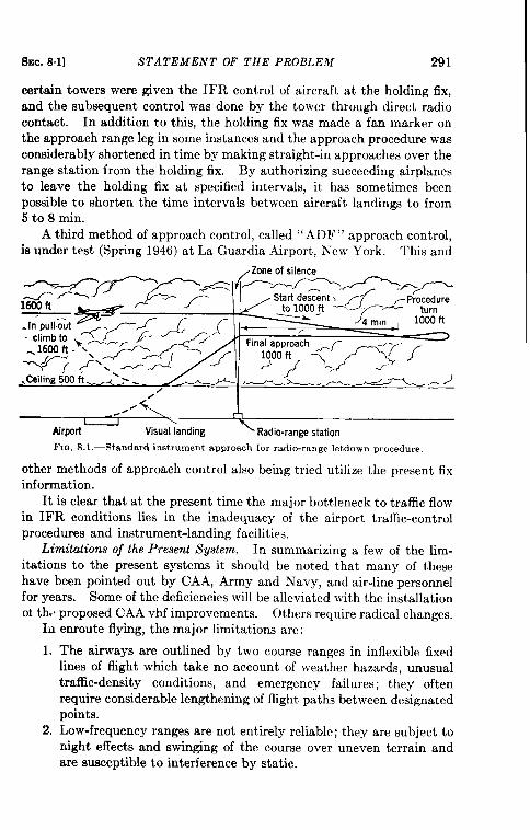
SEC. 81] STATEMENT OF THE PROBLEM 291
certain towers were given the IFR control of aircraft at the holding fix,and the subsequent control was done by the tower through direct radiocontact. In addition to this, the holding fix was made a fan marker onthe approach range leg in some instances and the approach procedure wasconsiderably shortened in time by making straight-in approaches over therange station from the holding fix. By authorizing succeeding airplanesto leave the holding fix at specified intervals, it has sometimes beenpossible to shorten the time intervals between aircraft landings to from5 to 8 min.
A third method of approach control, called “ ADF” approach control,is under test (Spring 1946) at La Guardia Airport, New York. This and
-. .,--- .<\
_#O” A\Airporl Visual landing < Radio-range station
FIG. S.1,—Standard instrument approach for radio-range letdown mocedure,
other methods of approach control also being tried utilize the present fixinformation.
It is clear that at the present time the major bottleneck to traffic flowin IFR conditions lies in the inadequacy of the airport traffic-controlprocedures and instrument-landing facilities.
Limitations of the Present System.—In summarizing a few of the lim-itations to the present systems it should be noted that many of thesehave been pointed out by CAA, Army and Navy, and air-line personnelfor years. Some of the deficiencies will be alleviated with the installationokth,, proposed CAA vhf improvements. Others require radical changes.
In enroute flying, the major limitations are:
1. The airways are outlined by two course ranges in inflexible fixedlines of flight which take no account of weather hazards, unusualtraffic-density conditions, and emergency failures; they oftenrequire considerable lengthening of flight paths between designatedpoints.
2. Low-frequency ranges are not entirely reliable; they are subject tonight effects and swinging of the course over uneven terrain andare susceptible to interference by static,
292 RADAR IN AIR NAVIGATION AND TRAFFIC CONTROL [SEC. S.1
3. Reported positional information as determined by the pilot fromdead reckoning, altimeter setting, and range fix data is not suf-ficiently accurate to prevent collision with other aircraft, partic-ularly unreported aircraft.
4. No warning for preventing collision with terrain can be given.5. Conflicting decisions result when the work load of normal data
coordination at the airway control center becomes excessivebecause of heavy traffic density.
6. The entire airplane-to-ground communication procedure of report-ing position and control information is complicated by the numberof messages sent, delays encountered, and inaccuracies transmitted.
7. The entire control procedure permits human failure on the groundwithout the pilot’s being aware of it. Also, because the groundstation possesses no direct evidence that its instructions are beingfollowed, a pilot’s error maybe unknown until long after it has hadserious consequences.
8. The restrictions that flight separation rules impose on traffic flow,necessitated by the infrequent and inaccurate positional informa-tion, limit traffic to a volume below even present requirements.
Radio ranges provide an inadequate number of approach paths intoairports. Navigational instruments do not give the pilot continuous andsufficiently accurate positional information. In short, no approachcontrol system which can handle the traffic requirements in regions ofheavy traffic flow exists. The lack is most serious in regions where thereare many airports.
Final-approach and landing traffic is hampered by the followingfactors:
1. The minimum letdown altitude on the radio-range legs cannotsafely be lowered. Because of the broadness of the range leg andthe use of the altimeter alone for obtaining elevation information,positional information as to the deviations of the airplane from asafe line of descent is not sufficiently accurate to permit descentbelow these minimums as a standard procedure.
2. The very limited traffic-handling capacity of the radio-range let-down procedure reaches, at best, 6 to 12 landings per hour. TheCAA-Army glide-path-localizer system (SCS-51), although animprovement over the radio-range procedure, can be flown success-fully only by an efficient instrument pilot.
3. No provision is made for emergency landing either of unequippedaircraft or of those in which airborne equipment has failed. Thereis no way for the ground personnel to monitor the descent of the
SEC. 82] USING AIRBORNE RADAR AIDS 293
aircraft and to warn the pilot of any dangerous departure from thelanding path or of the presence of other aircraft.
Availuble Radar Aids. —Both airborne and ground-based radars were
used during the World War II as aids to navigation and control of air-
craft but the problem of converting these to peacetime use is not simple.
Inpeacetime, safety ofoperation isof paramount importance. Further-
more, the traffic problem stems from large numbers of individual aircraft
and not from groups of aircraft, as in military situations. Fixed routes
and many navigational aids do, however, simplify some aspects of the
peacetime problem.
The limitations of our present navigational system indicate that an
air-traffic control and navigational system must be so designed that:
1. Weather conditions (poor visibility, thunderstorms, icing, static,etc. ) do not reduce safety requirements nor impose anv restrictionson the capacity of the system to handle air traffic. Ideally, thesystem should be efficient to the point that itsuse is advantageousunder all conditions of visibility.
2. All danger of collision between aircraft or between aircraft andterrain or fixed objects is removed.
3. It is capable of handling diversion or interruption in the flow oftraffic. For example, if hazardous weather conditions exist on oneair route the system must be able to divert traffic to an alternateroute.
4. It can detect and correct immediately an infraction of the airtraffic rules, whether voluntary or involuntary.
5. It is available to all classes of aircraft, commercial, military, andprivate.
With these requirements in mind, various types of airborne andground-based aids are now discussed.
8.2. Navigation and Traffic Control Using Airborne Radar Aids.’Information Conjtned to Aircrajt.—This extremely “airy” point of viewis suggested by consideration of present methods of navigation andtraffic control under CFR conditions. If radar instrumentation in theairplane can improve or at least equal CFR conditions and apply them toall-weather flying, present limitations on navigation and traffic controlwill be largely removed.
Under CFR conditions a pilot flies a flight plan over a certain routeand at a specified altitude. Once off the ground he is essentially on hisown. Avoiding obstructions, reporting position, navigation, approach,and landing are his responsibilities. Traffic patterns and runways are
1By J. H. Buck.
294 RADAR IN AIR NAVIGATION AND TRAFFIC CONTROL [SEC. 8.2
set up by the airport but the pilot’s ability to use and follow the patternsdepends on his ability to estimate his position. The radar instrumenta-tion necessary to carry out these procedures in either CFR or IFR isdiscussed here with respect to enroute, approach, and landing problems.
To fly the enroute zone between two airports, the pilot must be ableto ffy over the best route to his destination, to “see” and therefore toavoid collisions with terrain or other aircraft, and to avoid bad weather,particularly thunderheads. To carry out these requirements under allweather conditions the pilot should have, in addition to some of hispresent instruments, a scanning radar for navigation and detection of badweather and dangerous terrain ahead, and a radar collision-warningdevice preferably to scan through 360° in azimuth ( 180° possibly satis-factory) and i 30” in elevation. This collision-warning device must beable to detect approaching airplanes in time to allow the pilot to avoidthem.
The first requirement can be satisfied by very slight modifications ofpresent airborne systems. Navigation can be accomplished as discussedin Chap. 3, either by direct reference to the ground picture or by referenceto beacons on the PPI.
Ground speed and drift can be obtained from the picture and acourse followed fairly easily if the pilot is provided with appropriateradar maps. He cannot, however, expect to g!ance at the radar scopeevery half hour and be able to identify immediately the signals thatappear. A special navigator is not required, however, since either thepilot or the copilot can plot a course on radar maps.
The second alternative provides a system of ground beacons installedalong each airway to enable the pilot to fly a radar airway just as heflies visual beacons on a clear night. The beacons would be coded toavoid confusion of airways. Lateral separation with opposing trafficwould be maintained by flying to one side of the line of beacons. Becauseaircraft can be maintained fairly accurately at a fixed distance from theline of beacons, parallel airways along which airplanes can fly differentdktances from the beacon line can be set up.
With either method the radar gives the pilot a means of obtainingground speed and drift and allows him to obtain accurate range andbearing information on his check points in order to report proper fixes-adefinite improvement even over present CFR flying.
The most difficult problem to be solved in the enroute regionfor purely airborne equipment is that of collision. Although properscheduling and right-left separation along a radar airway reduce thehazard, the increased number of commercial and private airplanes is acomplicating factor. Under present CFR, the pilot sees only about 180°in azimuth and a few degrees vertically. This is sufficient to prevent
Sm. 82] USING AIRBORNE RADAR AIDS 295
collision with the terrain but not collisions with aircraft in heavy traffic.Any collision-warning device must therefore “see” at least this much,preferably with the addition of tail warning, and should give automaticindication of any dangerous condition.
If a reasonably good pencil beam is provided, a radar terrain-warningdevice can be obtained with present search equipment. AN/APS-10equipment without the cosecant-squared modification provides a fairlysimple set for this purpose and has an indicator that is easy to interpret.A narrower beam of 2° or 3° rather than the AN/APS-10 beam of 5°would improve the system.
The more difficult problem of aircraft-to-aircraft collision warning,was discussed in Sec. 4“Z. The long-range warning now required suggeststhe possibility of equipping the airplanes with beacons coded to givealtitude information so that warning is received only from aircraft in thesame altitude region. The beacon signals must appear in such a way asto give both range and altitude, perhaps on a PPI which could be com-bined with the main radar equipment.
It should be noted that in order to keep schedules under all weatherconditions all of the above airborne radar equipment is essential in anynonpressurized aircraft forced to fly over mountainous terrain. onlyairplanes equipped with both radars and beacons should be allowed tofly during instrument weather.
Somewhere near his destination the pilot reaches a point where hemust turn off the airway, mingle with traffic from other airways, and getinto a position for landing. This is the approach zone, which at presentis the bottleneck in IFR weather because of the separation requiredbetween aircraft. Using the airborne radar equipment suggested for theenroute zone, however, a pilot could follow a given route from the airways,and if cleared to land, turn into the landing pattern with traffic just ashe now does under CFR. Rules for this procedure would have to beestablished but they would allow the pilot to make his own decision,within the regulations, from the information he would have.
Because the general clutter of radar signals around most airportsmakes quick interpretation of a PPI picture for exact navigationextremely difficult, one of the most promising methods for providing thepilot with suitable information in the approach zone, as well as enroute,appears to be an approach pattern indicated by beacons.
To consistently land an airplane correctly, the pilot must have betterinformation from airborne radar then he now has under CFR. Withgood visibility the pilot turns from his approach pattern onto a glide-pathapproach to the end of the runway. But visual estimation of range andaltitude causes frequent bad landings and overshooting. To prevent this,the radar must not only give the pilot some sort of glide-path and azimuth
296 RADAR IN AIR NAVIGATION AND TRAFFIC CONTROL [SEC. 8.2
information but must also indicate how far he is from the field and, whenhe is not in the correct position, how far oil he is.
Some glide-path—localizer installations now in use can be modified togive the pilot most of this information without attempting to controlhis movements. A simple glide path, for instance, might be combinedwith an extension of a beacon approach path, which would preventseparation or change in procedure in the transition from enroute toapproach to landing. It is doubtful, however, whether a beacon localizercould provide the very high azimuth accuracy required to bring an air-craft down on a narrow runway. Thus, the best solution for purelyairborne radar appears to be a combination of a glide-path—localizersystem with a beacon path leading into it. The question still remainswhether this method of providing instrument landing is preferable to asystem like the ground control approach, GCA.
In sum then, it appears that under present traffic conditions an air-borne radar system can be devised that will gather enough informationfor the pilot to navigate efficiently from airport to airport in all weatherwith no more ground control than is at present exercised under CFRconditions. In all probability the system would require ground installa-tions such as radar beacons instead of the radio ranges and visual beaconsused under CFR. Furthermore, all aircraft flying under IFR wouldhave to carry radars and beacons in order to provide collision warning.Such a system appears to be essential for the future on open airways,particularly in mountainous terrain.
The final approach and landing zones present the greatest difficulties.In these zones the system will begin to fail in bad weather for the samereason that CFR flying fails—because of increased traffic. At present,most airports have no difficulty under CFR conditions, but traffic aroundNew York and Chicago is already reaching the point at which morecontrol is needed. Because of its ability to provide accurate fixes, air-borne radar will improve the congestion somewhat, with the result thatIFR traffic will be equal to present CFR traffic. If, however, trafficbecomes still heavier, policing to enforce strict adherence to the rules willbe necessary, and for this to be effective more knowledge will be requiredon the ground.
Information Relayed to Ground. -To prevent the confusion caused bythe airborne radar system under conditions of heavy traffic, coordinatingground agencies will be needed at busy centers to carry out more intensepolicing duties. This arrangement is almost analogous to our presentautomobile-traffic-control system—on the open highway certain safetyrules are occasionally enforced but otherwise the driver is left to his owndevices. As congested areas are approached, rules are more rigidly
SEC. 8.2] USING AIRBORNE RADAR AIDS 297
enforced, passing of other automobiles is limited, and in congested dis-tricts (asin the landing zone) the traffic is limited toa single line.
If the coordinating agency is to have a complete picture from theairborne radar systems the following minimum information is requiredfrom each airplane: first, position—range and bearing from a radar fix,and destination; second, ground speed and preferably air speed; third,altitude; and fourth, identification.
Overlooking for the moment the very important problem of airplane-to-ground communication that enters into any system of traffic control,let us consider the transfer of the above data from airplane to ground.In the enroute zone the data are transmitted primarily to provide anover-all picture for the coordinating agency so that it can forecast trafficconditions and aircraft arrivals at various airports. Airborne radar canprovide accurate position and ground-speed information which are ofprime importance here. Identification of the aircraft is of equal impor-tance in all zones and must be made an integral part of all transmissionsIn the enroute zone, altitude information is used only to determinewhether the aircraft is following the flight plan.
In the approach zone the altitude information becomes of equalimportance with the position and speed data. Because it is not possible
to maintain the 1000-ft separation in heavy traffic, the pilot and the
coordinating agency must have accurate altitude information. For
uniformity, this should be barometric altitude rather than terrain-
clearance data. The present barometric altimeter, if corrected for local
conditions, appears to be sufficiently accurate. Ideally a barometricaltimeter should have the following attachments:
1. A receiver with follow-up to feed corrective data to the altimeter so
that it may be corrected by ground stations transmitting local
barometric pressures.
2. A data take-off to a transmitter which sends out the altitude
signal of the airplane—for example, the take-off should change thefrequency of an oscillator in accordance with the altitude.
With these accurate position, speed, and altitude data at hand the
ground coordinating agency can predetermine traffic conditions and
know exactly when to slow down, detour, or hold aircraft.
Although in normal circumstances the information obtained from the
various aircraft will be sufficient to keep plots and to keep traffic operatingsmoothly, it is essential that an overriding policing control be providedfor emergency conditions. The ground coordinating centers can obtainadditional information from a few ground surveillance radars located
298 RADAR IN AIR NAVIGATION AND TRAFFIC CONTROL [~EIJ. 8.2
only at the busiest airports and possibly at intersections of a few congestedairways.
An Illustrative Flight.—It is possible to imagine the following flightbetween Chicago and San Francisco in a radar~quipped aircraft usingthis system. The pilot files a flight plan giving scheduled time of depar-ture, route to be flown, flight number (if commercial), type of aircraft,and scheduled time of arrival at destination. A few minutes beforedeparture time, the pilot is given clearance, exact time of take-off,cruising altitude, and points at which to climb and descend. In addition,he is given a summary of expected traffic conditions at various checkpoints along his route.
The pilot climbs to 1000 ft and flies toward a beacon 10 miles away,which marks the edge of the through airway. After the pilot has passedthe beacon he turns on course and climbs rapidly at the side of the airwayto a 20,000-ft cruising altitude, watching all the time for other aircraftbeacon signals. His PPI presents beacon responses from other trafficand indicates that all airplanes are at least 1 mile to his left; it alsocoincides with the traffic conditions predicted on his clearance chart.As he levels off at 20,000 ft he finds no traffic nearby so he swings in
toward the line of beacons and settles on course 5 miles to the right of
this line.
Let us suppose that the cabin pressurization begins to fail halfwaybetween Cheyenne and San Francisco. This immediately forces the air-plane down to at least 12,000 ft for the sake of the comfort and safet,yof the passengers; however, the pilot finds thunderstorms and very lowvisibility at this altitude. Under these conditions, flying amid highmountains would be extremely dangerous because static would causeindistinct radio ranges. With the airborne radar on combined search andbeacon operation, however, the pilot can continue his course, swinging offoccasional y to avoid tdunderheads that appear on the radar scope.The terrain-warning device in the aircraft enables the pilot to keep clearof dangerous peaks.
The control center at San Francisco has been notified of the change inflight and is kept informed of the progress of the aircraft as the pilotreports in at various check points. Because the airplane will arrive late,plans for its arrival are changed at the San Francisco control center tofit it in with other scheduled fights. As the aircraft approaches SanFrancisco, the control center informs the pilot that it is necessary to holdthe airplane for four minutes beyond the estimated time of arrival. On
receiving this information, the pilot cruises the last 75 miles at lower
speed. At the new scheduled time, he flies over the approach pattern
check point, follows the approach beacon into the glide-path—localizer
pattern, and lands the airplane safely.
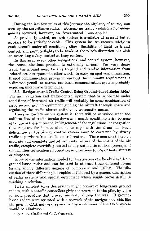
Ssu. 8.3] USING GROUND-BASED RADAR AIDS 299
During the last few miles of this journey the airplane, of course, wasseen by the surveillance radar. Because no traffic violations nor emer-gencies occurred, however, no “overcontrol” was applied.
As previously stated, no such system is available at present but itappears to be entirely feasible. This system insures utmost safety toeach aircraft under all conditions, allows flexibility of flight path andcontrol, and permits flights to be made at the pilot’s discretion but withan overriding safety control at busy centers.
In thk as in every other navigational and control system, however,the communications problem is extremely serious. For very densetraffic the ground must be able to send and receive information fromisolated areas of space—in other words, to carry on spot communication.If spot communication proves impractical the minimum requirement isa directed pencil- or narrow fan-beam communication system probablyrequiring microwave techniques.
8.3. Navigation and Traffic Control Using Ground-based Radar Aids.lThe air navigation and traffic-control system that is to operate underconditions of increased air traffic will probably be some combination ofairborne and ground equipment guiding the aircraft through space andregulating the traffic almost entirely by automatic means.
However perfect such a system is, there will be occasions when theuniform flow of traffic breaks down and unsafe conditions arise becauseof failure of the equipment, infringement of the regulations, or congestionthat requires the human element to cope with the situation. Suchdeficiencies in the airway control system must be corrected by airwaytraffic supervisors from traffic-control centers. These men must have anaccurate and complete up-to-the-minute picture of the status of the airtraffic, complete overriding control of any automatic control system, andthe facilities for sending information or directions to one or more aircraftor airspaces.
Most of the information needed for this system can be obtained fromground-based radar and can be used in at !east three different formshaving widely different degrees of complexity and utility. The dis-cussion of these different philosophies is followed by a general descriptionof radar systems and special equipment which might prove useful inreaching a solution.
In its simplest form this system might consist of long-range groundradars, with air-traffic controllers giving instruction to the pilot by voiceradio, a procedure that proved successful during the war. If ground-based radars were operated with a network of the navigational aids likethe present CAA network, several of the weaknesses of the CAA systemwould be eliminated.
1By M. A, Chaffeeand G, C. C,omstock.
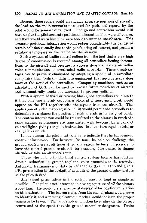
300 RADAR IN AIR NAVIGATION AND TRAFFIC CONTROL khio. 8.3
Because these radars could give highly accurate positions of aircraft,the load on the radio networks now used for positional reports by thepilot would be somewhat relieved. The ground controllers would stillhave to give the pilot accurate positional information if he were off-course,and they would warn him if he were about to enter an unsafe area. Thisaccurate positional information would reduce considerably the danger ofterrain collision (usually due to the pilot’s being off-course), and permit asubstantial increase in the traffic on the airways.
Such a system of traffic control suffers from the fact that a very highdegree of coordination is required among all controllers issuing instruc-tions to the aircraft and because its success depends heavily on radio-voice communication on overloaded radio networks. These disadvan-tages can be partially eliminated by adopting a system of intermediatecomplexity that feeds the data into equipment that automatically doesmost of the work of the controllers. Computing machines, such as anadaptation of GPI, can be used to predict future positions of aircraftand automatically sends out warnings to prevent collision.
With a system of fixed or moving blocks, the controllers could see toit that only one aircraft occupies a block at a time; each block wouldappear cm the PPI together with the signals from the aircraft. Thisapplication of video mapping (Sec. 7.12) would permit the controllers todetermine at a glance the position of each aircraft in its assigned block.The control information could be transmitted to the aircraft in much thesame manner as messages are transmitted with beacons, by a bank ofcolored lights giving the pilot instructions to hold, turn right or left, orchange his altitude.
In any system the pilot must be able to indicate that he has receivedcontrol information. Furthermore, he must be able to challenge theground controllers at all times if for any reason he feels it necessary tohave the control procedure altered, for example, if he desires to changealtitude or take an alternate route.
Those who adhere to the third control system believe that further
drastic reduction in ground-to-plane voice transmission is essential.
Automatic transmission of data by radar relay (Sec. 7.11) would give a
PPI presentation in the cockpit of as much of the ground display picture
as the pilot desired.
Any visual presentation in the cockpit must be kept as simple as
possible. The pilot is not interested in having a picture of all the aircraftabout him. He would prefer a pictorial display of his position in relationto his destination. The beacon signal from his own airplane would serveto identify it and a moving electronic marker would indicate the propercourse to be taken. The pilot’s job would then be to stay on the correctcourse and at the speed that the ground controller designates. Entire
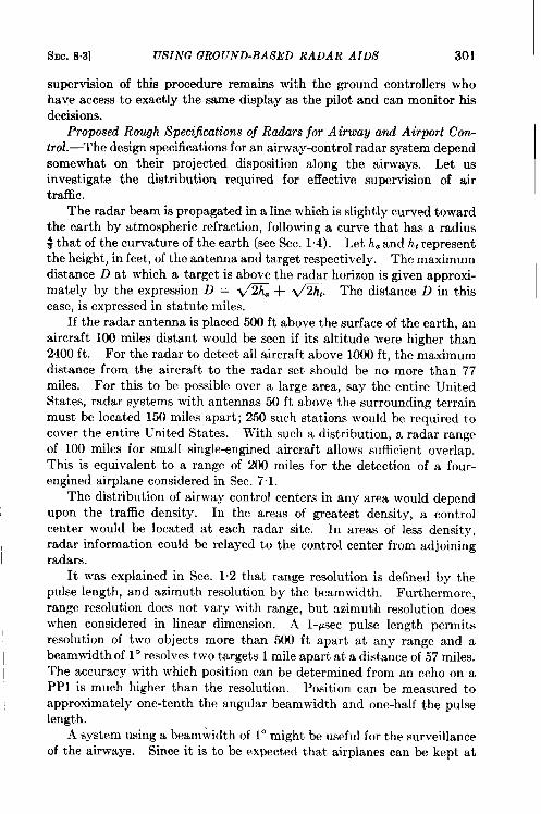
SEC. 8.3] USING GROUND-BASED RADAR AIDS 301
supervision of this procedure remains with the ground controllers whohave access to exactly the same display as the pilot and can monitor hisdecisions.
Proposed Rough Specijkcdions of Rruiars for Airway and Airport Con-trol.—The design specifications for an airway-control radar system dependsomewhat on their projected disposition along the airways. Let usinvestigate the distribution required for effective supervision of airtraffic.
The radar beam is propagated in a line which is slightly curved towardthe earth by atmospheric refraction, following a curve that has a radius~ that of the curvature of the earth (see Sec. 1.4). Let h. and h~representthe height, in feet, of the antenna and target respectively. The maximumdistance D at which a target is above the radar horizon is given approxi-mately by the expression D = &a + -. The distance D in thiscase, is expressed in statute miles.
If the radar antenna is placed 500 ft above the surface of the earth, anaircraft 100 miles distant would be seen if its altitude were higher than2400 ft. For the radar to detect all aircraft above 1000 ft, the maximumdistance from the aircraft to the radar set should be no more than 77miles. For this to be possible over a large area, say the entire UnitedStates, radar systems with antennas 50 ft above the surrounding terrainmust be located 150 miles apart; 250 such stations would be required tocover the entire United States. With such a distribution, a radar rangeof 100 miles for small single-engined aircraft allows sufficient overlap.This is equivalent to a range of 200 miles for the detection of a four-engined airplane considered in Sec. 7.1.
The distribution of airway control centers in any area would dependupon the traffic density. In the areas of greatest density, a controlcenter would be located at each radar site. In areas of less density,radar information could be relayed to the control center from adjoiningradars.
It was explained in Sec. 1.2 that range resolution is defined by thepulse length, and azimuth resolution by the beamwidth. Furthermorejrange resolution does not vary with range, but azimuth resolution doeswhen considered in linear dimension. A l-psec pulse length permitsresolution of two objects more than 500 ft apart at any range and abeamwidth of 10 resolves two targets 1 mile apart at a distance of 57 miles.The accuracy with which position can be determined from an echo on aPPI is much higher than the resolution. Position can be measured toapproximately one-tenth the angular beamwidth and one-half the pulselength.
A system using a beamwidth of 1° might be useful for the surveillanceof the airways. Since it is to be expected that airplanes can be kept at
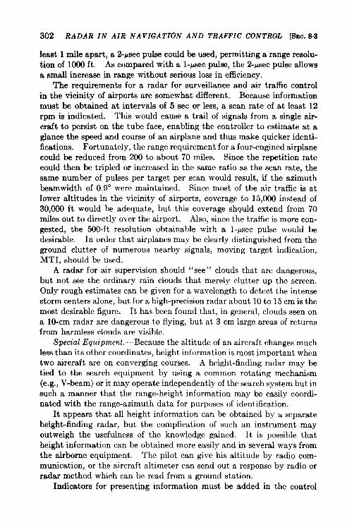
302 RADAR IN AIR NAVIGATION AND TRAFFIC CONTROL [SEC. 83
least 1 mile apart, a 2-psec pulse could be used, permitting a range resolu-tion of 1000 ft. As compared with a l-~sec pulse, the 2-~sec pulse allowsa small increase in range without serious loss in efficiency.
The requirements for a radar for surveillance and air traffic controlin the vicinity of airports are somewhat clifferent. Because informationmust be obtained at intervals of 5 sec or less, a scan rate of at least 12rpm is indicated. This would cause a trail of signals from a single air-craft to persist on the tube face, enabling the controller to estimate at aglance the speed and course of an airplane and thus make quicker identi-fications. Fortunately, the range requirement for a four-engined airplanecould be reduced from 200 to about 70 miles. Since the repetition ratecould then be tripled or increased in the same ratio as the scan rate, thesame number of pulses per target per scan would result, if the azimuthbeamwidth of 0.9° were maintained. Since most of the air traffic is atlower altitudes in the vicinity of airports, coverage to 15,000 instead of30,000 ft would be adequate, but thk coverage sh@d extend from 70miles out to directly over the airport. Also, since the traffic is more con-gested, the 500-ft resolution obtainable with a l-psec pulse would bedesirable. In order that airplanes may be clearly distinguished from theground clutter of numerous nearby signals, moving target indication,MTI, should be used.
A radar for air supervision should “see” clouds that are dangerous,but not see the ordinary rain clouds that merely clutter up the screen.Only rough estimates can be given for a wavelength to detect the intensestorm centers alone, but for a high-precision radar about 10 to 15 cm is themost desirable figure. It has been found that, in general, clouds seen ona lo-cm radar are dangerous to flying, but at 3 cm large areas of returnsfrom harmless clouds are visible.
Special Equipment.—Because the altitude of an aircraft changes muchless than its other coordinates, height information is most important whentwo aircraft are on converging courses. A height-finding radar may betied to the search equipment by using a common rotating mechanism(e.g., V-beam) or it may operate independently of the search system but insuch a manner that the range-height information may be easily coordi-nated with the range-azimuth data for purposes of identification.
It appears that all height information can be obtained by a separateheight-finding radar, but the complication of such an instrument mayoutweigh the usefulness of the knowledge gained. It is possible thatheight information can be obtained more easily and in several ways fromthe airborne equipment. The pilot can give his altitude by radio com-munication, or the aircraft altimeter can send out a response by radio orradar method which can be read from a ground station.
Indicators for presenting information must be added in the control
SEC. 83] USING GROUND-BASED RADAR AIDS 303
room or installed in a special radar control room so that radar informationadded to the control tower can be coordinated with the nonradar dataalready available at the tower.
As in the airway control centers, a large PPI will be the principalindicator for search data. Experience with experimental equipmentindicates so far that the clutter-free off-center PPI with a video-mappingfeature is a most effective device in supplying the airport controller withan up-to-the-minute picture of his traffic problem.
At present, the 12-in. PPI appears to be the best one available com-mercially; a 20-in. PPI is now being used for experimental purposes.Tubes with brighter traces may soon be available for use in less subduedlight. A study of other types of indicators such as dark- and bright-tracetubes, photographic projection, etc., should be made to see whetherindications can be obtained that are more effective and more adaptableto the partially or completely lighted rooms than are the ordinary CRT’S.
The ability to add the exact position of runways, other airfields, radioranges, holding points, etc. to the azimuth picture and to be able to off-center the picture without distortion has been found to be a most vital aid.
The operator should be able to use at will any one of several rangesweeps equipped with corresponding fixed range marks and angle marks,to choose normal radar video signals or MTI video signals, to add video-mapping features, and to add such identification aids as indications ofdirection-finding equipment using communication radio or the responseto beacons in target aircraft.
Another attachment useful for controlling aircraft presents the radiodirection-finding bearing on the PPI. This is best done by a rotatingshaft of light wi Lh the PPI map center as the center of rotation. Therotating is synchronized by remote methods with the direction-findingequipment. When a radio reception is made, the shaft of light intersectsthe radar echo of that aircraft and gives immediate identification. Thismeans of identification is much more effective than that which dependsso heavily on the commonly used flight plan. As traffic increases, stillmore positive means of identification can be achieved by installing abeacon in each aircraft. The beacon, triggered by the radar beam, givesa response which can be coded for positive identification of the aircraft.Fortunately, beacons can be made light enough to be installed in smallprivate airplanes. The number of PPI’s used depends on the density oftraffic. Each PPI should display no more than an area in which thenumber of aircraft does not exceed what the controller can efficientlyhandle. One great advantage of radar is that it can handle increasedtraffic density merely by the addition of more displays. In regionsof low traffic density, one controller with one PPI can do the entire job.High traffic density, on the other hand, may require as many as twelve
304 RADAR IN AIR NAVIGATION AND TRAFFIC CONTROL [SEC. 83
controllers and twelve PPI’s. Although radar could cope with this situa-tion, it may overload the limited number of radio channels.
To avoid the danger of collision, one-way traffic lanes which wouldconsist of two vhf radio beams parallel to each other, each for traffic inopposite directions, have been suggested. Assignment of differentaltitudes for different speeds would make this a smooth-flowingsystem.
The crossing airways present another problem that has been partiallysolved by assigning odd altitudes for, say, the east-west, and even for thenorth-south, airways. There is, however, the ever-present possibilityof error in altitude, especially in private airplanes where check on theinstruments is not so rigid. A radar height finder could detect thiserror, but the number of height finders required would be very great.Perhaps the best solution would be to give the pilot more informationabout surrounding aircraft.
This discussion of the incorporation of ground-based radar into theair-traffic-control system has been based on the premise that any system oftraffic control is improved by increasing the accuracy of the data. Thesecond premise is that additional equipment should not be added to theaircraft, with the possible exception of a radar beacon. Such a modifica-tion would not require a simultaneous change in the entire system butwould occur at the rate at which radar equipment is made available.The suggested radar equipment and aids for control are those actuallyused in wartime. Other aids can be devised or adopted to reduce furtherthe guesswork on the part of the controllers.
The introduction of search radar into the air-traffic-control systemwill not solve the problem completely, but it will temporarily alleviatethe present difficulties. Unless more efficient ways are devised to controlaircraft, the control system will soon bog down with increased traffic.If it is assumed that control is to be exercised when two aircraft pass onan airway, it can be shown that the number of passings increase as (n/2)2where n is the number of aircraft. This means that a 10-fold increase intraffic would require a 25-fold increase in work by the controllers. Anattempt should be made, therefore, to increase the efficiency of each con-troller in order to avoid a tremendous increase in controller personnel.
Control in Approach Zones.—The complexity of the control problemmay vary from just a few airplanes per hour in the approach zone totraffic densities of 150 to 200 per hour, which the major airfields in a largemetropolitan area like New York must handle. The amount of radarindicating equipment required depends partly on the traffic load. Theway in which the radar information is utilized in the control procedure isbound up in the general problems of how human controllers or mechanicalcontrol devices are to compile this information, what kind of traffic
SEC. 8.3] USING GROUND-BASED RADAR AIDS 305
patterns and flight procedure~ are to be used, and how control instructionsare to be issued to the pilots.
There are at least three general viewpoints of the problem of approachcontrol that merit discussion. The first two of these are based on supply-ing control information over voice radio channels. The third wouldtransmit the control information either as automatic coding or as relayedpictorial reformation to be presented in display or meter form to the pilot.
As an introductory and interim procedure, it has been suggested thatthe tower controllers should bc supplied with one or two PPI’s as supple-mentary sources of information, and a range-height indicator mountedinto the control desks. This may possibly eliminate the reporting-over-fix procedures now used by pilots to supply ground controllers with posi-tional data, and hence greatly reduce aircraft-to-ground communication.
It has been suggested also that with radar surveillance of the existingstacking areas, the present holding procedures could be retained withmodifications allowed by the additional position knowledge supplied thecontroller from the radar indicator scopes, and result in reduction of thetime separation of the airplanes emerging from such a stack to 2 or 3minutes with no reduction in the degree of safety now attainable. Sucha method of control would not attempt to produce exact spacing betweenaircraft nor to eliminate the stack forming. If airplanes could be broughtin with 2- to 3-rein spacings rather than the 12- to 15-rein spacings nownecessary, it is expected that for the next few years instrument-flyingtrafic densities would not be so great as to require large holding stacks.
It is very doubtful whether tower controllers could benefit much fromradar scope data without almost continuous concentration on the scopepresentation. It seems probable that the controller finding himselfmore and more dependent on the radar data will wish that either he him-self or an assistant become essentially a PPI operator. It is difficult tosee how these indicators can be added to the tower without an increasein control personnel since with high handling rates the function of groundcontrol will be likewise intensified.
Although this limited application of radar information may alleviatisome congestion for a few years and can be considered as a necessary stepin the education of tower personnel in radar techniques, little real advancein safety and efficiency of control can be expected without a very radicalchange in the fundamental procedure. Such a change is suggested by thesecond viewpoint which involves expanding the control room of the towerinto a radar operating center. This means an increase in personnel toobtain and coordinate positional data and to issue control information,and the addition of automatic mechanical or electronic devices to aid inthe analysis of routine problems, thereby releasing human controllers formore important duties.
306 RADAR IN AIR NAVIGATION AND TRAFFIC CONTROL l~EC. 8.3
Such a control room need not involve the large number of personnelassociated with similar radar centers for control of military aircraft duringthe war. It does, however, assign definite tower personnel to scopepositions to observe continuously changing radar data. It is thoughtthat the use of three or four PPI’s to observe particular sectors either inazimuth or range maybe required, with a height-finder operator to furnishheight data. The use of large plotting-boards in approach zone controlis not considered so economical in manpower and time.
Senior or master controllers will have to supervise the analysis of theinformation presented. One of their major jobs will be to effect thedesired spacing between the airplanes being directed off or onto the air-ways. Paper study and the little experimental evidence that is availableshow that if a specified control pattern is to be followed this spacingcannot be accomplished without the aid of correlating devices to indicateto the controllers the relation between the actual and desired position ofevery airplane.
One means of accomplishing this is to add to the PPI indicators eithermechanically, optically, or electronically, a series of mowing lines or dotsspaced according to the desired separation. These lines would beassigned to the different airplanes approaching the field from the differentairways. The controller’s function would be to give the pilot whateverinstructions are necessary to keep his airplane coincident with the cor-responding line or pip. If traffic patterns called for feeding afl airplanesinto the airport through a common point, such lines might be a series ofconcentric circles about the “gate” point. Vacant spaces could be leftin the pattern to provide holding spaces for itinerant aircraft or thosemakmg emergency landings.
Control in Final Approwh and Landi~.-The navigational informa-tion and traffic-control procedures utilized in the approach to an airporthave put the aircraft into such a position relative to the runway that thepilot can begin his final instrument approach at a safe interval fromaircraft in front of and behind him.
The following appear to be the major requirements for an instrumentapproach system:
1. The system must provide the pilot with aural or visual informationas to hk position with respect to a safe glide path. This sense ofrelative position must be in both horizontal and vertical planesand must be of sufficient accuracy and of such easily interpretablepresentation to allow the pilot to make a desmnt to within a fewfeet of the runway surface, from which point a visual landing ismade. For a completely blind landing, the pilot must be supplied
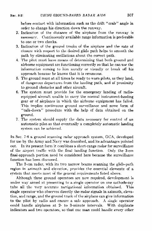
SEC. 83] USING GROUND-BASED RADAR AIDS 307
before contact with information such as the drift “crab” angle inorder to change his direction down the runway.
2. Indication of the distance of the airplane from the runway isnecessary. Continuously available range information is preferableto one or two checks.
3. Indication of the ground tracks of the airplane and the rate ofclosure with respect to the desired glide path helps to smooth thepath by eliminating oscillations about the correct path.
4. The pilot must have means of determining that both ground andairborne equipment are functioning correctly so that he can use theinformation coming to him aurally or visually or break off hisapproach because he knows that it is erroneous.
5. The ground must at all times be ready to warn pilots, as they land,of dangerous departures from the landing path, and of proximityto ground obstacles and other aircraft.
6. The system must provide for the emergency landing of radio-equipped aircraft unable to carry the normal instrument-landinggear or of airplanes in which the airborne equipment has failed.This implies continuous ground surveillance and some form of“talk-down” procedure with the help of data obtained on theground.
7. The system should supply the data necessary for control of anautomatic pilot so that eventually a completely automatic landingsystem can be achieved.
In Sec. 7.8 a ground scanning radar approach system, GCA, developedfor use by the Army and Navy was described, and its advantages pointedout. In its present form it combines a short-range radar for surveillanceof the airport traffic with the final landing function. Only the 3-cmfinal-approach portion need be considered here because the surveillancefunction has been discussed.
The 3-cm radar, with its two narrow beams scanning the glide-pathregion in azimuth and elevation, provides the essential elements of asystem that meets most of the general requirements listed above.
Although three ground operators are now required, development isunder way aimed at presenting to a single operator on one cathode-raytube all the very accurate navigational information obtained. Thissingle operator who observes directly the radar signals in azimuth, eleva-tion, and range, and the ground track of the airplane can give informationto the pilot by radio and ensure a safe approach. A single operatorcould handle airplanes at 2- to 3-minute intervals. With duplicateindicators and two operators, so that one man could handle every other
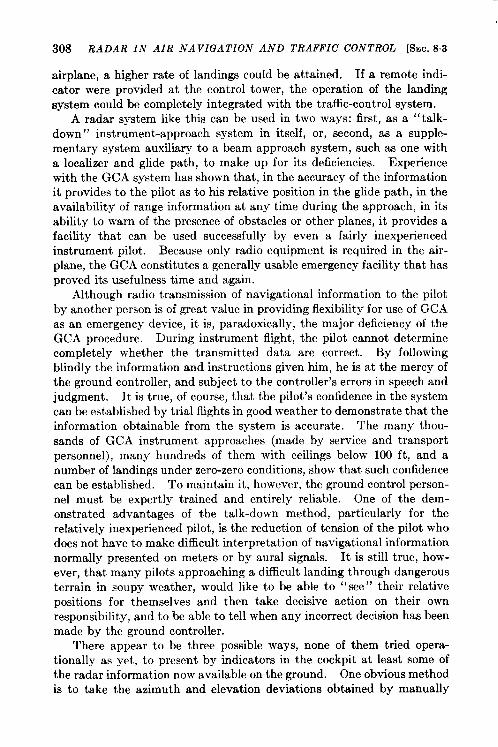
308 RADAR IN AIR NAVIGATION AND TRAFFIC CONTROL [SEC. 83
airplane, a higher rate of landings could be attained. If a remote indi-cator were provided at the control tower, the operation of the landingsystem could be completely integrated with the traffic-control system.
A radar system like this can be used in two ways: first, as a “talk-down” instrument-approach system in itself, or, second, as a supple-mentary system auxiliary to a beam approach system, such as one witha localizer and glide path, to make up for its deficiencies. Experiencewith the GCA system has shown that, in the accuracy of the informationit provides to the pilot as to his relative position in the glide path, in theavailability of range information at any time during the approach, in itsability to warn of the presence of obstacles or other planes, it provides afacility that can be used successfully by even a fairly inexperiencedinstrument pilot. Because only radio equipment is required in the air-plane, the GCA constitutes a generally usable emergency facilit y that hasproved its usefulness time and again.
Although radio transmission of navigational information to the pilotby another person is of great value in providing flexibility for use of GCAas an emergency device, it is, paradoxically, the major deficiency of theGCA procedure. During instrument flight, the pilot cannot determinecompletely whether the transmitted data are correct. By followingblindly the information and instructions given him, he is at the mercy ofthe ground controller, and subject to the controller’s errors in speech andjudgment. It is true, of course, that the pilot’s confidence in the systemcan be established by trial flights in good weather to demonstrate that theinformation obtainable from the system is accurate. The many thou-sands of GCA instrument approaches (made by service and transportpersonnel), many hundreds of them with ceilings below 100 ft, and anumber of landings under zero-zero conditions, show that such confidencecan be established. To maintain it, however, the ground control person-nel must be expertly trained and entirely reliable. One of the dem-onstrated advantages of the talk-down method, particularly for therelatively inexperienced pilot, is the reduction of tension of the pilot whodoes not have to make difficult interpretation of navigational informationnormally presented on meters or by aural signals. It is still true, how-ever, that man y pilots approaching a difficult landing through dangerousterrain in soupy weather, would like to be able to “see” their relativepositions for themselves and then take decisive action on their ownresponsibility, and to be able to tell when any incorrect decision has beenmade by the ground controller.
There appear to be three possible ways, none of them tried opera-tionally as yet, to present by indicators in the cockpit at least some ofthe radar information now available on the ground. One obvious methodis to take the azimuth and elevation deviations obtained by manually
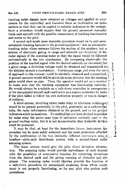
SEO. 8.3] USING GROUND-BASED RADAR AIDS 309
tracking radar signals (now obtained as voltages and applied to errormeters for the controller) and transmit them as modulation on radiocarriers so that they can be applied to suitable indicators in the cockpit.Such a procedure would require that the ground personnel manuallytrack each aircraft with the possible transmission of tracking inaccuraciesand errors to the pilot.
A second and much more desirable procedure would be to add semi-automatic tracking features to the ground equipment—not an automatic-tracking radar whose antenna follows the motion of the airplane, but asystem of electronic gating in range and azimuth (or elevation) of theradar signals of the scanning radar so that the signal would be followedautomatically in the two coordinates. By comparing electrically theposition of the tracked signal with the desired azimuth (or elevation)” for [, ‘~a given range, a deviation voltage could be obtained and transmitted to [. ,~the airplane as such a modulation. Continuous range, and even the rate ~<. ~of approach to the runway, could be similarly obtained and transmitted. ( ~A ground operator would still be given his scope pictures, but the tracking Egates would show as pips. Thus, the operator would act as a monitor “” )
to. make sure that the tracking equipment was functioning correctly. (, )He would always be available as a talk-down controller in emergencies ~ >or for unequipped aircraft and could serve as a master controller by radio { jif the pilot failed to follow his own indication properly or was in danger [ ~of collision.
A third system, involving either radar relay or television techniq , s: qEwould be to present pictorially to the pilot, preferably on a cathode-, y’ ‘
tube, the radar information obtained on the ground, and to use gro~dindicators solely as monitors. ;No method has yet been devised to present ,by radar relay the sector scan type of indication normally used in the ;ground landing radar, but it is not inconceivable that workable devi(xs ;could be produced.
It may be that, at least for the immediate future, instrument ~p- ~preaches can be most safely achieved and the most protection affordedby the combination of the two distinctly different microwave aids~_a_; ,.-=localizer-glide-path fixed-beam system with a ground-based radarscanning system.
The beam system would give the pilot direct deviation informa-tion. The scanning radar would provide surveillance of each descentwith the possibility of overcontrol function for correcting deviationsfrom the desired path and for giving warning of obstacles and air-planes. The scanning radar would likewise provide the function ofa talk-down procedure for unequipped airplanes, those whose equip-ment is not properly functioning, or for any pilot who prefers suchprocedures.
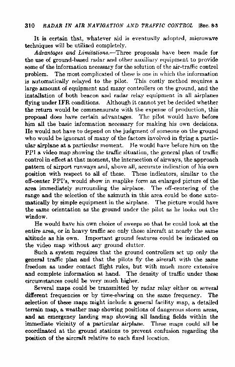
310 RADAR IN AIR NAVIGATION AND TRAFFIC CONTROL [8EC. 8,3
It is certain that, whatever aid is eventually adopted, microwave
techniques will be utilized completely.
Advantages and Limitations. —Three proposals have been made for
the use of ground-based radar and other auxiliary equipment to provide
some of the information necessary for the solution of the air-traffic controlproblem. The most complicated of these is one in which the information
is automatically relayed to the pilot. This costly method requires a
large amount of equipment and many controllers on the ground, and the
installation of both beacon and radar relay equipment in all airplanesflying under IFR conditions. Although it cannot yet be decided whether
the return would be commensurate with the expense of production, this
proposal does have certain advantages. The pilot would have before
him all the basic information necessary for making his own decisions.
He would not have to depend on the judgment of someone on the ground
who would be ignorant of many of the factors involved in flying a partic-
ular airplane at a particular moment. He would have before him on the
PPI a video map showing the traffic situation, the general plan of traffic
control in eflect at that moment, the intersection of airways, the approach
pattern of airport runways and, above all, accurate indication of his own
position with respect to all of these. These indicators, similar to the
off-center PPI’s, would show in maplike form an enlarged picture of the
area immediately surrounding the airplane. The off-centering of the
range and the selection of the azimuth in this area could be done auto-
matically by simple equipment in the airplane. The picture would have
the same orientation as the ground under the pilot as he looks out th~
window.
He would have his own choice of sweeps so that he could look at the
entire area, or in heavy traffic see only those aircraft at nearly the samealtitude as his own. Important ground features could be indicated on
the video map without any ground clutter.
Such a system requires that the ground controllers set up only thegeneral trafiic plan and that the pilots fly the aircraft with the samefreedom as under contact flight rules, but with much more extensiveand complete information at hand. The density of traffic under thesecircumstances could be very much higher.
Several maps could be transmitted by radar relay either on severaldifferent frequencies or by time-sharing on the same frequency. Theselection of these maps might include a general facility map, a detailedterrain map, a weather map showing positions of dangerous storm areas,and an emergency landing map showing all landing fields within theimmediate vicinity of a particular airplane. These maps could all becoordinated at the ground stations to prevent confusion regarding theposition of the aircraft relative to each fixed location.
SEC. 8.4] SUMMARY OF PROPOSED AIDS 311
The same general procedure could be used both on the airway and inthe approach zones. As an approach for landing was to be made, theamount of information required would be considerably increased. Itseems reasonable to suppose however, that techniques can be developedwhich would enable the pilot to land under IFR conditions with little orno dependence on the judgement of ground controllers. These lastwould direct traffic and monitor all landings without giving detailedinstructions.
On the airways and in the approach zones, the pilot would have athis disposal information fl om a radar having 360° azimuth coverage,adequate vertical coverage, high resolution in both range and azimuth,no ground return, and a range of at least 100 miles on all types of aircraft.The complicated equipment requiring skilled personnel, together withsuitable stand-by equipment, would be on the ground. Only relativelysimple equipment capable of presenting all the available information,and probably not weighing more than 75 lb, would be in the aircraft.
8.4. Summary of Proposed Aids. ‘—The last two sections havedescribed how airborne and ground-based radar equipment may be usedto help solve the problems of control of air traffic. Although the opinionsexpressed in the two preceding sections differ in their emphasis on therelative importance of airborne or ground-based equipment in solvingthe problems, there is agreement as to what a specific airborne or ground-based radar can do. The uncertainty lies for the most part in regionswhere human factors predominate. It is clear that a careful plan includ-ing the best combination of aids to traffic control and air navigation mustbe put into operation before there can be a substantial increase in airtraffic under IFR conditions.
Airborne radar aids alone can greatly improve navigational accuracyand help the pilot avoid bad weather and terrain collision. Traffic lanesalong the airways can be delineated by coded ground-based beacons.Collision warning against other aircraft probably can be achieved only ifbeacons are required for all aircraft flying under IFR conditions. Air-borne radar should be particularly useful in overwater flight where thepilot must often obtain his own weather information and where thenumber of aircraft would be so small that beacon standardization couldbe more easily achieved.
Ground-based radars can provide more information but require asubstantial outlay of money for establishing a network of radar controlcenters over the entire country. In spite of the expense, these wouldremove the necessity of having the same airborne beacon installed in alltypes of aircraft as a safeguard against collision. A PPI presentationrelayed from the ground to the airplane should allow the pilot considerable
1By J. S. Hall.
312 RADAR IN AIR NAVIGATION AND TRAFFIC CONTROL [SEC. 8.4
freedom of action, and at the same time permit the ground controller tomonitor and control the traffic. In regions of uneven terrain this systemwill have blind areas but these can often be made small by mountingthe antennas at commanding positions.
Improved ground facilities such as GCA or a glide-path—localizer andbeacon arrangement might be used as aids to landing under conditionsof very poor visibility. High-intensity lights and fog dispersal methodseffectively raise the ceiling under conditions of poor visibility and provideadded safeguards when used with the facilities mentioned above. Atcongested airports, ground surveillance radars might be used advantage-ously to control traffic at all times.
To repeat, a combination of airborne and ground-based aids isindicated. Whether the eventual solution puts the main emphasis onairborne or ground-based equipment, the principal difficult will beencountered at or near the airports where there is a definite limit to thenumber of aircraft that can be controlled. Means of accurate navigationin the airplane will help simplify the situation and reduce the load onthe controllers.
It would be sadly negligent not to emphasize the close relationship ofradars, beacons, and communication equipment. The frequencies andcodes used for the radar-beacon combination and for radio communica-tion must be rigidly standardized. It is of no use to try to interl ogate abeacon with a radar which transmits at the wrong frequency or does notrespond to the frequency of the beacon reply; it is of little avail toreceive a coded beacon reply and not know what it means. Furthermore,it does not help a radar controller to know that two airplanes are oncollision courses and then to find himself unable to communicate witheither.
Even under the stimulus of war the Combined CommunicationBoard was not able to achieve a unified system. Although the outlookfor the peacetime standardization of beacons on an international scaleis not bright, standardization may be possible within the boundaries ofthe United States because such coordination comes directly under thejurisdiction of the Federal Communications Commission. Otherwise,confusion and a considerable waste of money and materials will resultfrom lack of coordinated planning.
A number of interested groups, including the CAA, the Army, theNavy, the commercial air liies, and private fliers, are concerned with thegeneral problem of air-traffic control. It appears to be necessary that asmall, highly competent group of men (working it is hoped, in closecooperation with similar groups in other countries) be empowered toselect the best solution, the adoption of which would be mandatory.
SEC. 84] S’UMMAR Y OF PROPOSED AIDS 313
Obviously, these men must be carefully chosen to ensure a whollyimpartial anal ysis of the probl~m.
The question of who would pay for these radar aids naturally arises.At first thought, it might be supposed that all equipment in the aircraftshould belong to its owner, and that the ground-based equipment wouldbe paid for partly by the government, partly by a tax on owners ofprivate aircraft, and partly by a surcharge on fares for travel on com-mercial air lines. The economic aspect of the problem is beyond thescope of this book. Any solution must, of necessity, include stand-ardization of all equipment. This may necessitate government owner-ship and operation of ground-based equipment and government supplyof airborne equipment on a rental basis. A company might be estab- ●
lished for this very purpose.The cost to the government of modernizing its air navigation and
traffic-control system may be comparable to what it expends on other aidsto navigation. These include maintenance of lighthouses and other use-ful markers, dredging of rivers and harbor entrances, etc. It alsomaintains the United States Coast Guard, whose chief peacetime functionis to safeguard the lives of mariners in distress. Few, if any, questionthe value of these services. From a strictly economic viewpoint theincrease of air traffic resulting from such a modernization might morethan compensate for its cost.
The advisability of interim measures and piecemeal installationswhich are not a part of long-range planning is questioned. Althoughthese might put more airplanes in the air in the next few years, theywould also be expensive and eventual standardization would be retardedbecause of natural reluctance to displace such interim equipment. Eventhough the growth of air travel in the near future might be delayed by tak-ing time to work out a comprehensive syst em, the long-range advantagewould more than make up for the temporary delay.
In conclusion, it is necessary to emphasize again the importance ofmaking it possible for a small group of able men to study this problem,to formulate a solution, and to dictate a policy. These men may makemistakes, and their dictatorial power might be ob jactionable from somepoints of view. But it is possible only in some such way to bring orderout of chaos and save the American public vast sums of money.


PART IV
SHIPBORNE RADAR

CHAPTER 9
NAVIGATION AND PILOTAGE
BY R. M. EMBERSON, J. P. NASH, E. E. MILLER, D. B. MCLAUGHLIN,AND C. A. SMITH
9.1. How Radar Can Help the Navigator. ‘—There is perhaps nopeacetime application of radar where its advantages are so clearlyindicated as in shipborne navigation. Wartime experience has shownclearly that even a simple radar is so useful that its cost is very smallcompared to the return, especially for freighters and passenger shipsengaged in world-wide or coastwise trade. The use of radar shouldreduce the danger of collision to such an extent that vessels so equippedmight often proceed at full speed even under conditions of poor visibility,thus saving one or two days in passage. Furthermore, at their destina-tions, they could be docked without delay under conditions which wouldotherwise be impossible.
It was shown in Chap. 2 how long-range electronic navigationalsystems like Loran may be used as aids to navigation far at sea. It wasalso explained how the direction-finding stations along the coast cangive navigators fixes within a range of 100 or 200 miles. When landmasses rise above the optical horizon, shipborne radar becomes importantas an aid to navigation or pilotage. After a land mark has once beenidentified, the navigator may easily determine its bearing to one or twodegrees and its range with an accuracy of 100 or 200 yd. This far exceedsthe capabilities of a human eye, or even of optical devices such as stadio-meters and range finders. In short, the navigator may determine a fixwith an accuracy far greater than that to which he has been accustomed.
Pilots in harbors, rivers, and lakes find radar information extremelyhelpful. The photographs in this section are of PPI’s attached to setsespecially designed to provide both high and close-in resolution. Theirimportant characteristics are narrow beamwidth, short pulse length, andfast indicator sweeps. Figure 1.17 (Sec. 1.8) shows an aerial photographof the Sagamore end of the Cape Cod Canal and a PPI photograph show-ing the entrance of the canal taken on a ship about a mile offshore. Fig-ure 9.1 shows two photographs taken while the ship was actually passingthrough the canal. The range circle has a diameter of 2000 yd. It is
i Sections9.1 to 9,3 by R. M. Emberson.317
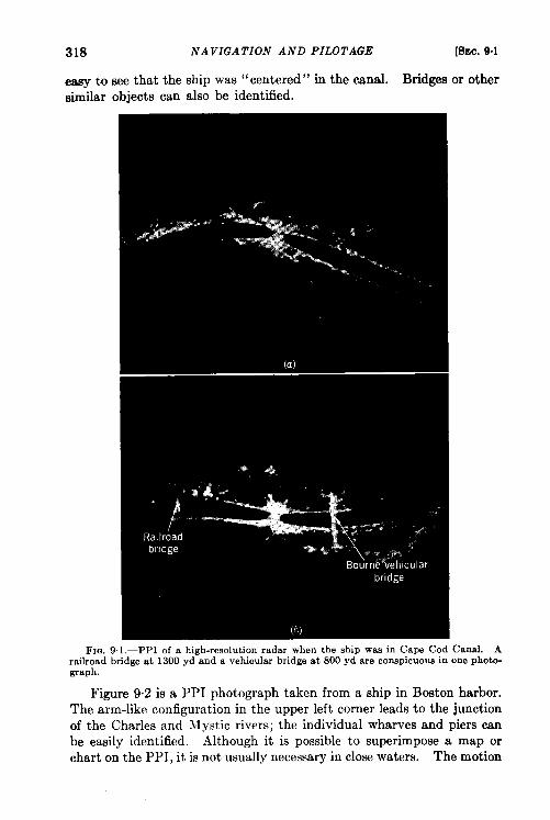
318 NAVIGATION AND PILOTAGE [SEC.9.1
easy to see that the ship was “centered” in the canal. Bridges or othersimilar objects can also be identified.
FIG. 91. -PPI of a high-resolution radar when the ship was in Cape Cod Canal. Arailroad bridge at 1300 yd and a vehicular bridge at 800 yd are conspicuous in one photo-graph.
Figure 9.2 is a PPI photograph taken from a ship in Boston harbor.The arm-like configuration in the upper left corner leads to the junctionof the Charles and Mystic rivers; the individual wharves and piers canbe easily identified. Although it is possible to superimpose a map orchart on the PPI, it is not usually necessary in close waters. The motion
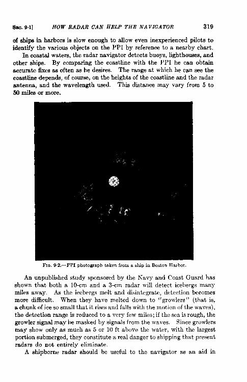
SM. 9.1] HOW RADAR CAN HELP THE NAVIGATOR 319
of ships in harbors is slow enough to allow even inexperienced pilots toidentify the various objects on the PPI by reference to a nearby chart.
In coastal waters, the radar navigator detects buoys, lighthouses, andother ships. By comparing the coastline with the PPI he can obtainaccurate fixes as often as he desires. The range at which he can see thecoastline depends, of course, on the heights of the coastline and the radar~tenna, and the wavelength used. This distance may vary from 5 to50 miles or more.
F1m 9.2.—PPI photograph taken from a ship in Boston Harbor.
An unpublished study sponsored by the Navy and Coast Guard hasshown that both a 10-cm and a 3-cm radar will detect icebergs manymiles away. As the icebergs melt and disintegrate, detection becomesmore difficult. When they have melted down to “growlers” (that is,a chunk of ice so small that it rises and falls with the motion of the waves),the detection range is reduced to a very few miles; if the sea is rough, thegrowler signal may be masked by signals from the waves. Since growlersmay show only as much as 5 or 10 ft above the water, with the largestportion submerged, they constitute a real danger to shipping that presentradars do not entirely eliminate.
A shipborne radar should be useful to the navigator as an aid in
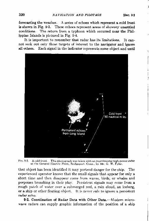
3!20 NAVIGATION AND PILOTAGE [SEC. 9.2
forectiing the weather. A series of echoes which represent a cold frontis shown in Fig. 93. These echoes represent areas of showery unsettledconditions. The return from a typhoon which occurred near the Phil-ippine Islands is pictured in Fig. 9.4.
It is important to remember that radar has its limitations. It can-not seek out only those targets of interest to the navigator and ignoreall others. Each signal in the indicator represents some object and until
FIG. 93.-A cold front. This photograph was taken with an experimental high-power radarat the General Electric Plant, Bridgeport, Corm., by Mr. G. W. Fyler.
that object has been identified it may portend danger for the ship. Theexperienced operator knows that the small signals that appear for only ashort time and then disappear come from waves, birds, or whales andporpoises broaching in their play. Persistent signals may come from arough patch of water over a submerged reef, a rain cloud, an iceberg,or a ship or other floating object. It is never safe to ignore a persistentradar echo.
9.2. Coordination of Radar Data with Other Data. -Modern micro-wave radars can supply graphic information of the position of a ship
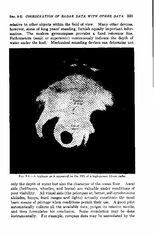
SW. 9.2] COORDINATION OF RADAR DATA WITH OTHER DATA 321
relative to other objects within the field of view. Many other devices,
however, some of long years’ standing, furnish equally important infor-
mation. The modern gyrocompass provides a fixed reference line.
Fathometers (sonic or supersonic) continuously indicate the depth ofwater under the keel. Mechanical sounding devices can determine not
Fro. 94.-A typhoon as it appeared on the PPI of a high-power 10-cm radar
only the depth of water but also the character of the ocean floor. Aural
aids (bellbuoys, whistles, and horns) are valuable under conditions of
poor visibility. All visual aids (the peloruses or, better, self-synchronous
alidades, buoys, fixed ranges and lights) actually constitute the most
basic means of pilotage when conditions permit their use. A good pilot
automatically collects all the available data, judges its relative merits,
and then formulates his conclusion. Some correlation may be done
instrumentally. For example, compass data may be assimilated by the
322 NAVIGATION AND PIJZOTAGE [SEC. 9.3
radar to provide a true bearing display. But, in general, the mpara~
instruments are too divergent in character to permit an easy and simple
combination. Radar information should be presented on the bridge or
at another point convenient for the pilot or navigator in such form that
it can be seen and understood at a glance without need of deliberate
mental gymnastics.
9.3. Marine Radar Beacons.—Although radar beacons were widely
used for air navigation during the war, the war ended before they could
be put into operation for marine use. It is apparent, nevertheless, that
they could have been extremely useful.
Location.-In regions where there are a large number of accurately
charted and easily identifiable radar target~in harbors, for example
the capabilities of existing marine radars are such that beacons may have
little to contribute to safety and ease of navigation. The shortest
beacon codes now in use are 2 to 3 miles long and they might so clutter
up the indicator that beacons actually would be undesirable. (Shorter
codes can be used when expanded sweeps are in common use.) But, on
the other hand, codes might be unnecessary in such locations; the beacon
could reply with a single pip, which the operator would recognize as a
beacon simply because the signals were received on the beacon frequency
rather than the radar frequency. This would be practical only in
locations where one beacon could not be mistaken for another.
Beacons would probably be of the greatest value when a ship ap-
proaches a coastline or enters a harbor where the number of useful points
of navigation is relatively small.
There are intermediate waters like Chesapeake Bay and Puget Sound,
for which it is difficult to make a prior judgment. In Puget Sound,
in particular, the channels are lined on both sides by high land masses
that give false echoes because of the weak side and back lobes of the
antenna pattern. These echoes obscure targets in other directions.
Low-powered beacons might prove useful here.
Operational Use.—The techniques described in Sec. 3.8 for air nav-
igation with beacons could be applied in marine navigation, but because
the speed of a surface vessel is much less than that of an airplane the
beacons would be most useful in simply getting continuous running
fixes.
Beacon signals tend to spread in azimuth at short ranges if the
receiver gain is not reduced. High land masses near the ship may act
as mirrors and reflect radar signals to the beacon and beacon signals
back to the radar. Under these conditions, also, the false signals can
sometimes be eliminated by reducing the receiver gain. The problem is
primarily one of beacon siting, discussed at greater length in Radar Bea-cons, Vol. 3, Radiation Laboratory Series.
am.941J MARINE RADAR BEACON8 333
Beacon Design.-The use of interrogation coding was d~cussed inSec. 1“9. There it was stated that the purposes are to reduce the demandson the beacon transmitter and to eliminate partly the false signals that
are seen when more than one radar is interrogating the beacon. Beacon
transmitters can be designed to withstand any likely overloading.Clumsy and complicated as they might be, they would permit simpli-fication of the radar. Because there will be far fewer beacons than radars,
the use of powerful beacon transmitters would be an economical solution
to this problem, but interrogation coding helps solve the problem of false
signals in regions of dense traffic.
The density of traffic on the seaward side of a coastline beacon mightbe small, and its antenna could be designed to be insensitive to inter-rogation from harbors and other waters carrying heavy marine traffic onthe landward side. In such a case, interrogation coding would be unnec-essary. Unless it can be shown, however, that in every location either(1) the situation is such that beacons are not needed or (2) the marinetraffic within a range of several miles will never be very dense, it wouldappear that interrogation coding should be used
Beacon signals will be of benefit only at limited ranges, except incoastline installations. Since the signals from a sensitive and powerful
beacon are displayed as very wide arcs on the PPI of a nearby ship,
sensitivity and transmitter power of the beacon receiver should be
limited in some locations.From this discussion and that in Sec. 19, these rough specifications
for marine radar beacons can be set down:
1. The maximum range of each beacon should be determined by itsparticular location.
2. The receiver should cover the entire marine scatter band.3. The beacon should contain an interrogation decoder if it is so
situated that traffic conditions warrant it.4. The transmitter must be accurately held to the assigned frequency,
preferably by an automatic mechanism.
Radar Design.—The operator should be able to switch radar echoes orbeacon signals, or both together, onto the indicator. When both arepresented, the beacon signals should be appreciably brighter than theechoes. This means that there should be a beacon receiver with a highervideo output level that is separate from the radar receiver.
There may be a delay of as much as 2 or 3 psec in the beacon response.This is important when fast sweeps are being used. It may be compen-sated for by delaying the sweeps an equal amount. When echoes andbeacon signals are to be presented together, the echoes must also bedelayed.
324 NA VKJATION AND PILOTAGE [Smc. 9-4
In the past, the most common form of interrogation coding w= along pulse, which requires a somewhat complicated modulator and oftena reduced pulse-repetition rate. The coding may be done, however, byusing two or more short pulses of the same total length as a single searchpulse. Another method, which was used with IFF sets during the war,is to have a second low-frequency radar interrogator synchronized withthe microwave set. The beacon operates only when signals are receivedsimultaneously from both radar and interrogator.
The rough specifications for the marine radar to operate with beacons,then, may be summarized as follows:
1. Interrogation coding.2. A separate beacon receiver with a video output level higher than
that of the radar receiver.
3. Provision for presenting the output of the receivers separately or
together.
4. For extreme accuracy with fast sweeps it is desirable that compen-
sation be made for the delay of the beacon response.
9.4. Comer Reflectors. -It is sometimes desirable to increase theradar reflecting properties of a target to make its echo stand out moreclearly on the indicator. During the war, it was found that rubber liferafts could not be detected by radar sets of searching aircraft. When aspecial target, called a corner reflector, was included as part of the emer-gency rescue equipment of the rafts, however, they could be detectedfrom a range of many miles.
Corner-reflector buoy markers should prove to be a valuable aid topilotage because some buoys are difficult to detect, especially the nunbuoys which have smooth curved surfaces. Bell buoys are more easilydetectable, but even the echo from one of these will be more prominentif a corner reflector is mounted on it. This is especially true when the sea
is rough and sea return obscures the relatively weak signal from a buoy.
Radar pilotage along a channel can be carried out easily under all visibil-
it y conditions if all buoys are easily detectable. Corner reflectors placed
at strategic positions on land can sometimes solve marking problems.
This is possible where the land signals are weaker than those from the
corner reflectors.
Corner reflectors have also been used to intensify the echoes fromsmall boats. They would aid materially if used in small boats on fishing
banks, both to keep the boats from being run down by ships when visibil-
ity is poor and to enable a radar-equipped mother ship to keep track of
them. Echoes from an 8-ft corner reflector attached to a meteorological
I BY J. P. Nash.
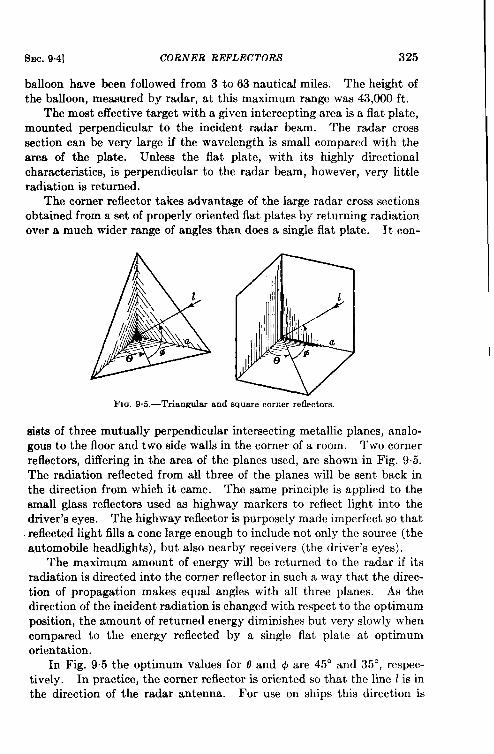
SEC. 9.4] CORNER REFLECTORAS 325
balloon have been followed from 3 to 63 nautical miles. The height ofthe balloon, measured by radar, at this maximum range was 43,000 ft.
The most effective target with a given intercepting area is a flat plate,mounted perpendicular to the incident radar beam. The radar crosssection can be very large if the wavelength is small compared with thearea of the plate. Unless the flat plate, with its highly directionalcharacteristics, is perpendicular to the radar beam, however, very littleradiation is returned.
The corner reflector takes advantage of the large radar cross sectionsobtained from a set of properly oriented flat plates by returning radiationover a much wider range of angles than does a single flat plate. It con-
F1o. 9.5.—Triangular and square corner reflectors.
sists of three mutually perpendicular intersecting metallic planes, analo-gous to the floor and two side walls in the corner of a room. Two cornerreflectors, differing in the area of the planes used, are shown in Fig. 9.5.The radiation reflected from all three of the planes will be sent back inthe direction from which it came. The same principle is applied to thesmall glass reflectors used as highway markers to reflect light into thedriver’s eyes. The highway reflector is purposely made imperfect so thatreflected light fills a cone large enough to include not only the source (theautomobile headlights), but also nearby receivers (the driver’s eyes).
The maximum amount of energy will be returned to the radar if itsradiation is directed into the corner reflector in such a way that the direc-tion of propagation makes equal angles with all three planes. As thedirection of the incident radiation is changed with respect to the optimumposition, the amount of returned energy diminishes but very slowly whencompared to the energy reflected by a single flat plate at optimumorientation.
In Fig. 9.5 the optimum values for o and @ are 45° and 35°, respec-tively. In practice, the corner reflector is oriented so that the line 1is inthe direction of the radar antenna. For use on ships this direction is
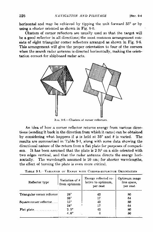
326 NA VIGA TIOiV AND PILOTAGE [SEC, 9.4
horizontal and may be athieved by tipping the unit forward 35° or byusing a cluster oriented as shown in Fig. 9.6.
Clusters of corner reflectors are usually used so that the target willbe a good reflector in all directions; the most common arrangement con-sists of eight triangular corner reflectors arranged as shown in Fig. 9.6.This arrangement will give the proper orientation to four of the cornerswhen the search radar antenna is directed horizontally, making the orien-tation correct for shipboard radar sets.
FIG. 9.6.—Clusters of corner reflectors.
An idea of how a corner reflector returns energy from various direc-tions (sending it back in the direction from which it came) can be obtainedby considering what happens if @ is held at 35° and o is varied. Theresults are summarized in Table 9.1, along with some data showing thedirectional nature of the return from a flat plate for purposes of compari-son. It has been assumed that the plate is 2 ft 2 on a side oriented withtwo edges vertical, and that the radar antenna directs the energy hori-zontally. The wavelength assumed is 10 cm; for shorter wavelengths,the effect of turning the plate is even more critical.
TABLE 91.-VARIATION OF RANGE WITH CORNER-REFLECTOR ORIENTATION
Reflector typeVariation of Ofrom optimum
1
Triangular corner reflector 26”33”
Square corner reflector. 15°24”
Flat plate . . . . . . . . . . . . . . . 2.5°4.0°
Fmergy reflected re-lative to optimum,
per cent
4217421742
6 I
Optimum rangefree space,
per cent
so648064w50
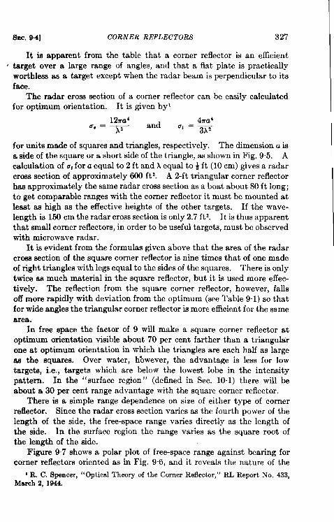
Slrc. 9.4] CORNER REFLECTORS 327
It is apparent from the table that a corner reflector is an efficient, target over a large range of angles, and that a flat plate is practically
worthless as a target except when the radar beam is perpendicular to itsface.
The radar cross section of a corner reflector can be easily calculatedfor optimum orientation. It is given by’
for units made of squares and triangles, respectively. The dimension a isa side of the square or a short side of the triangle, as shown in Fig. 9.5. Acalculation of u~for a equal to 2 ft and h equal to i ft (10 cm) gives a radarcross section of approximately 600 ft 2. A 2-ft triangular corner reflectorhas approximately the same radar cross section as a boat about 80 ft long;to get comparable ranges with the corner reflector it must be mounted atlead as high as the effective heights of the other targets. If the wave-length is 150 cm the radar cross section is only 2.7 ft 2. It is thus apparentthat small corner reflectors, in order to be useful targets, must be observedwith microwave radar.
It is evident from the formulas given above that the area of the radarcross section of the square corner reflector is nine times that of one madeof right triangles with legs equal to the sides of the squares. There is onlytwice as much material in the square reflector, but it is used more effec-tively. The reflection from the square corner reflector, however, fallsoff more rapidly with deviation from the optimum (see Table 9.1) so thatfor wide angles the triangular corner reflector is more efficient for the same
In free space the factor of 9 will make a square corner reflector atoptimum orientation visible about 70 per cent farther than a triangularone at optimum orientation in wlich the triangles are each half as largeas the squares. Over water, Kowever, the advantage is less for lowtargets, i.e., targets which are below the lowest lobe in the intensitypattern. In the “surface region” (defined in Sec. 10.1) there will beabout a 30 per cent range advantage with the square corner reflector.
There is a simple range dependence on size of either type of cornerreflector. Since the radar cross section varies as the fourth power of thelength of the side, the free-space range varies directly as the length ofthe side. In the surface region the range varies as the square root ofthe length of the side.
Figure 97 shows a polar plot of free-space range against bearing forcorner reflectors oriented as in Fig. 96, and it reveals the nature of the
1R. C. Spencer, “Optical Theory of the Corner Reflector,” RL Report No. 433,March 2, 1944,
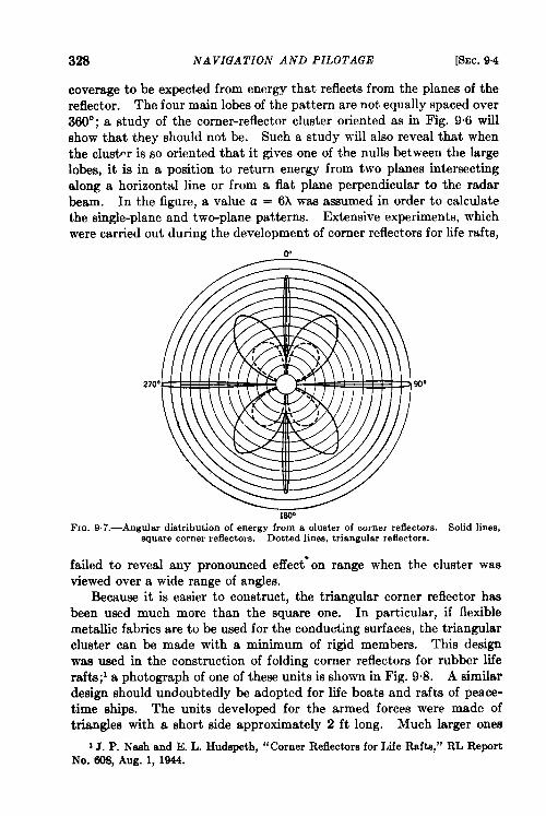
328 NAVIGATION AND PILOTAGE [SEC. 9.4
coverage to be expected from energy that reflects from the planes of thereflector. The four main lobes of the pattern are not equally spaced over360°; a study of the corner-reflector cluster oriented as in Fig. 9“6 willshow that bhey should not be. Such a study will also reveal that whenthe clustw is so oriented that it gives one of the nulls between the largelobes, it is in a position to return energy from two planes intersectingalong a horizontal line or from a flat plane perpendicular to the radarbeam. In the figure, a value a = 6X was assumed in order to calculatethe single-plane and two-plane patterns. Extensive experiments, whichwere carried out during the development of corner reflectors for life rafts,
90”
F1~. 9,7.—Angdar distribution of energy from a cluster of corner reflectors. Solid lines,square corner reflectors. Dotted lines, triangular reflectors.
failed to reveal any pronounced effect’ on range when the cluster wasviewed over a wide range of anglea.
Because it is easier to construct, the triangular corner reflector hasbeen used much more than the square one. In particular, if flexiblemetallic fabrics are to be used for the conducting surfaces, the triangularcluster can be made with a minimum of rigid members. This designwas used in the construction of folding corner reflectors for rubber liferafts;1 a photograph of one of these units is shown in Fig. 9.8. A similardesign should undoubtedly be adopted for life boats and rafts of peace-time ships. The units developed for the armed forces were made oftriangles with a short side approximately 2 ft long. Much larger ones
1J. P. Nash and E. L. Hudspeth, “Corner Reflectors for Life Rafts,” RL ReportNo. 608, Aug. 1, 1044.
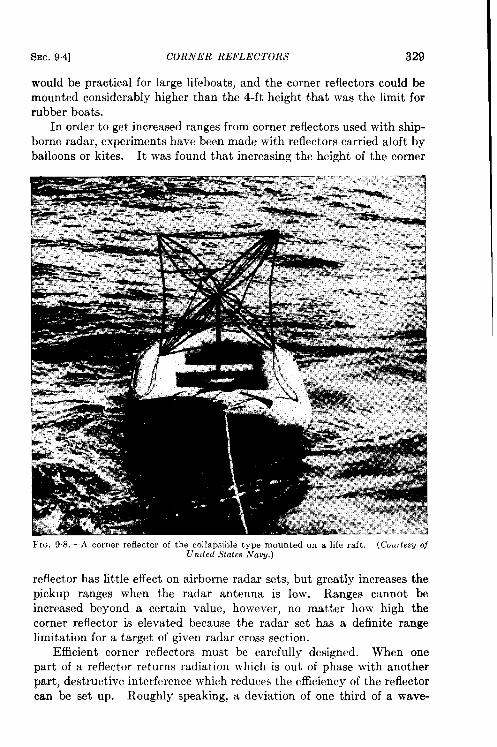
SEC. 9.4] CORNER REFLECTORS 329
would be practical for large lifeboats, and the corner reflectors could bemounted considerably higher than the 4-ft height that was the limit forrubber boats.
In order to get increased ranges from corner reflectors used with ship-borne radar, experiments have been made with reflectors carried aloft byballoons or kites. It was found that increasing the height of the corner
FIG. 9S,-A corner reflector of the collapsible type mounted on a life raft, (Courtesy ofUnited States Naoy.)
reflector has little effect on airborne radar sets, but greatly increases the
pickup ranges when the radar antenna is low. Ranges cannot be
increased beyond a certain value, however, no matter how high the
corner reflector is elevated because the radar set has a definite range
limitation for a target of given radar cross section.
Efficient corner reflectors must be carefully designed. When one
part of a reflector returns radiation which is out of phase with another
part, destructive interference which reduces the efficiency of the reflectorcan be set up. Roughly speaking, a deviation of one third of a wave-
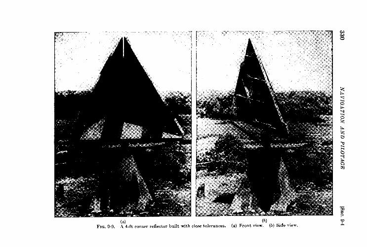
330N
AV
IGA
TIO
NA
ND
PIL
OT
AG
E[S
EC
.9.4
I%c. 9.5] PRINCIPLE OF SUPERPOSITION NAVIGATION 331
length at the outside edge of the three planes of a corner reflector willreduce the signal strength by one half. As the size of the corner isiacrerwwd, therefore, the resulting angukzr tolerance allowed in construc-tion becomes small. For example, if a triangular corner reflector withlegs 2 ft long is to return at least one half of the 10-cm radiation incidentupon its effective area at optimum orientation, the allowable error inconstruction of the three angles is 3.3°. For a wavelength of 3 cm thiswould be only 1°. The tolerances for square corner reflectors with thesame edge sizes are even smaller. Three errors of about two thirds of awavelength at the edge reduce the reflected energy by about 90 per cent.
If a corner reflector is to be used as a marker where weight is not animportant factor, it can be made very accurate. 1 The 4-ft experimentalmodel shown in Fig. 9.9 weighs 315 lb exclusive of the base and costs about$1~. (This is to be compared with a cost of a few dollars apiece forreflectors used in life rafts; in Sec. 6“7 the cost of a ground-based beaconis estimated at $20,000.) The accuracy of construction was such that itseffective cross section at 1.25 cm was found experimentally to agree withthe theoretical value of 600,000 ftz.
The echo from this reflector at 1.25 cm was slightly stronger than thatfrom a standard wooden airplane hangar 217 ft long and 160 ft wide.It could be detected at 30 miles with an experimental airborne 1.25-cmradar. A l-in. displacement of one side caused the signal to disappear inthe ground clutter. The ease with which this corner could be made tomodulate the echo by moving one side made it easy to identify its echo.It was not possible to identify its echo with a 3-cm radar.
In sum, corner reflectors used with microwave radar have manypossible applications. Although it may not be possible to distinguish a4-ft reflector from ground clutter at 3 or 10 cm, the possibility of usinglarger reflectors and shorter wavelengths should not be overlooked.
9s6. Principle of Superposition Navigation. ~When a radar set isoperating within range of land, its indicator displays a pattern whichresembles the actual land configuration. If the operator can match theradar pattern by superposing a map on it he can easily and accuratelydetermine his position with respect to the land. The recognition of thePPI pattern is a prerequisite to the solution of many shipborne and airborne navigational problems.
Recognition.-Recognition is based upon the study of one or more ofthe following properties: (1) the relative signal intensities expected fromthe various topographical features and buildings; (2) the vertical dimen-sion (height) which controls shadows and which—because of the curva-
‘E. G. Martin, “ Design of a 4-ft Corner Reflector for K-band,” RL Report No.642, Aug. 20, 1945.
* By E. E. Miller.
332 NAVIGATION AND PILOTAGE [SEC. 9.5
ture of the earth-controls the dktance at which objects are visible: and(3) their relative positions and shapes in the horizontal plane.
Of these, the first is not very reliable, but the second and third aregeometric properties which can be analyzed quantitatively. The secondproperty, the effect of height, can be analyzed by using terrain modelswith a point of light to replace the radar; thk approach, however, istedious and subject to serious deficiencies such as the variation of PPIpatterns with variations in atmospheric refraction.
The third property is the most useful and can be put into convenientquantitative form merely by optical superposition on the PPI of a maphaving the same number of miles per inch. When the position of the mapis adjusted to match the radar pattern, each point on the map coincideswith a corresponding point on the PPI. Thus, the relative positions andshapes of all features are easily and accurately compared, and the relativepositions of objects with respect to each other are independent of theposition of the radar set.
It is very much easier to identify a PPI pattern by matching to it asuperposed image of a map than it is to find a resemblance between thetwo when they are observed side by side. The effects of curvature of theearth, shadowing, spreading of signals in azimuth due to the finite beam-width of the radar, and the presence of a few ships on the water fre-quently combine to make a PPI pattern have little evident resemblanceto the map. This pattern can, nevertheless, be lined up easily bysuperposition so that (1) each signal (except those attributable to ships,etc.) coincides exactly with a map feature which would reasonably beexpected to give a signal, and (2) conversely, no map feature whichshould definitely give a return fails to have its superposed signal. Thevariations in the pattern caused by the effects of atmospheric refractionand the unpredictable variations in relative signal strengths of varioustypes of land features do not preclude consistently reliable results.Thk, then, is a basic point: the quantitative comparison of relativepositions on the map and the PPI forms so good a recognition tool thatit overrides the inability to predict just what kind of a PPI pattern isexpected; in fact, it normally requires the use of only a small fraction ofthe qualitative knowledge that we possess concerning radar signals.
By the use of superposition, the relative positions and shapes of allsignals can be ascertained very quickly. Some of these signals are simpleand consistent, as are those from land-water boundaries for example.Others, like the difference between a river and flat land, may be confus-ing—sometimes the river is brighter than the land because of trees andbuddings which line it; sometimes the reverse is true. But regardless ofwhether the course of the river is brighter or darker, so long as it matchesits map counterpart in shape and position, and is consistent with the
ISEC. 95] PRINCIPLE OF SIJPERPOSITION NAVIGATION 333
other features, it contributes to recognition of the pattern by super-position.
A question frequently raised by those unfamiliar with the techniqueis: What happens when the shoreline is straight and featureless? Anumber of deliberate attempts have been made to find such a shoreline.They have always failed.
Matching Techniques.—As in airborne radar, it is necessary to vary
the receiver gain control over a wide range in order to extract all of the
useful information from the radar. Fortunately, there is normally an
oversupply of information so that two or three convenient settings of gain
control will suffice. The use of a three-tone I?PI which shows informa-
tion from two gain settings at two brightness levels, would obviously be
a convenience, especially if the gain of the two levels could be varied at
will. At full gain, a set with ample range ~vill tend to block in a solid
mass of signals from every land area within line of sight. Full receiver
gain is, therefore, desirable for getting the initial rough match between
the map and the PPI.
Any PPI pattern should be regarded as being made up of the return
from a large number of point reflectors on the map. These reflectors
can have a variety of signal strengths. The return from each point will
appear as a broadened signal on the PP1, centered on the associatedpoint of the map. The amount of broadening of individual signals
depends upon the effective beamwidth of the antenna and may be
decreased by turning down the gain so that many weak signals disappear,
isolating the stronger ones.
It has been found by experience that many strong signals are locatedexactly on the shoreline. This is probably a combination of three
circumstances:
1. Many houses, docks, sea walls, etc., are built along shorelines.2. The objects on the shore are the nearest ones.3. Shoreline objects are reflected in the water.
Whatever the reason, the phenomenon is very helpful because it makespossible the use of an isolating process for determining the proper positionof the shoreline.
When properly matched, the shoreline should bisect exactly a numberof signals which are isolated by gain reduction (see Fig. 9“10). It isexpected that a large number of inland signals which, of course, are notbisected by the map shoreline will remain. Although ships may bevisible on the seaward side, their signals remain isolated even at highgain, and so do not confuse the situation. The number of signals notbisected by the shoreline is immaterial, provided it bisects exactly aconsiderable number of signals.
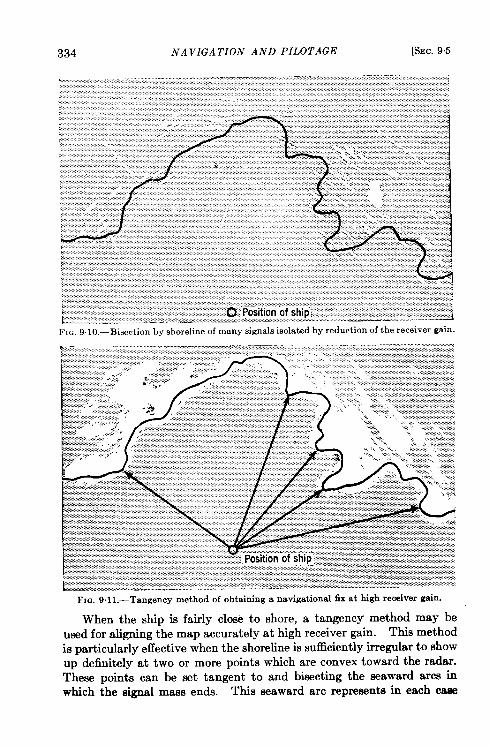
334 NAVIGATION AND PILOTAGE [SEC. 95
FIG. 9.1 I.—Tangency method of obtaining a navigational fix at high receiver gain.
When the ship is fairly close to shore, a tangency method may beused for aligning the map accurately at high receiver gain. Thk method
is particularly effective when the shoreline is sufficient y irregular to showup definitely at two or more points which are convex toward the radar.These points can be set tangent to and bisecting the seaward arcs inwhich the signal mass ends. This seaward arc represents in each cass
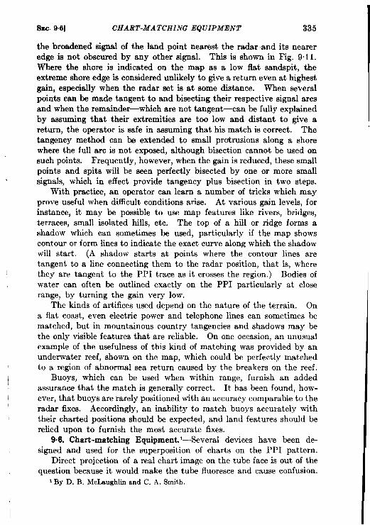
I
II
SEC- 9.6] CHART-MA TCHIiVG EQUIPMENT 335
the broadened signal of the land point nearest the radar and its neareredge is not obscured by any other signal. This is shown in Fig. 9.11.Where the shore is indicated on the map as a low flat sandspit, theextreme shore edge is considered unlikely to give a return even at highestgain, especially when the radar set is at some distance. When severalpoints can be made tangent to and bisecting their respective signal arcsand when the remainder—which are not tangent—can be fully explainedby assuming that their extremities are too low and distant to give areturn, the operator is safe in assuming that his match is correct. Thetangency method can be extended to small protrusions along a shorewhere the full arc is not exposed, although bisection cannot be used onsuch points. Frequently, however, when the gain is reduced, these smallpoints and spits will be seen perfectly bisected by one or more smallsignals, which in effect provide tangency plus bisection in two steps.
With practice, an operator can learn a number of tricks which mayprove useful when difficult conditions arise. At various gain levels, forinstance, it may be possible to use map features like rivers, bridges,terraces, small isolated hills, etc. The top of a hill or ridge forms ashadow which can sometimes be used, particularly if the map showscontour or form lines to indicate the exact curve along which the shadowwill start. (A shadow starts at points where the contour lines aretangent to a line connecting them to the radar position, that is, wherethe y are tangent to the PPI trace as it crosses the region.) Bodies ofwater can often be outlined exactly on the PPI particularly at closerange, by turning the gain very low.
The kinds of artifices used depend on the nature of the terrain. Ona flat coast, even electric power and telephone lines can sometimes bematched, but in mountainous country tangencies and shadows may bethe only visible features that are reliable. On one occasion, an unusualexample of the usefulness of this kind of matching was provided by anunderwater reef, shown on the map, which could be perfectly matchedto a region of abnormal sea return caused by the breakers on the reef.
Buoys, which can be used when within range, furnish an addedassurance that the match is generally correct. It has been found, how-ever, that buoys are rarely positioned with an accuracy comparable to theradar fixes. Accordingly, an inability to match buoys accurately withtheir charted positions should be expected, and land features should berelied upon to furnish the most accurate fixes.
9.6. Chart-matching Equipment. ‘—Several devices have been de-signed and used for the superposition of charts on the PPI pattern.
Direct projection of a real chart image on the tube face is out of the
question because it would make the tube fluoresce and cause confusion.i By D. B. McLaughlin and C. A. Smith.
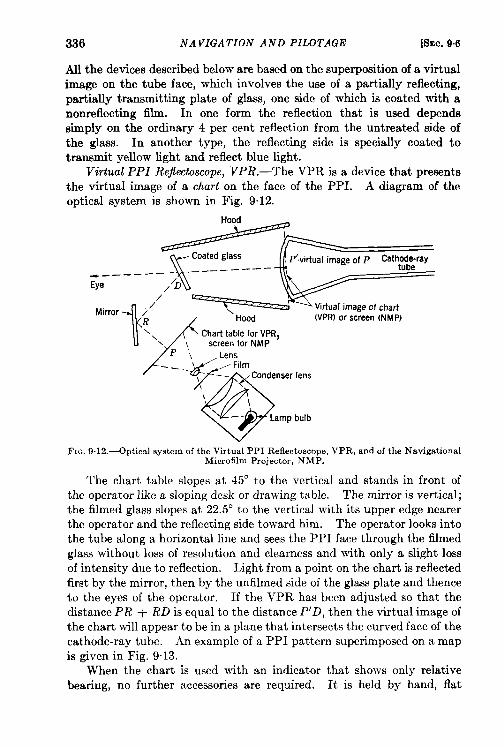
336 NAVIGATION AND PILOTAGE [SEC. 96
All the devices described below are based on the superposition of a virtualimage on the tube face, which involves the use of a partially reflecting,partially transmitting plate of glass, one side of which is coated with anonreflecting film. In one form the reflection that is used dependssimply on the ordinary 4 per cent reflection from the untreated side ofthe glass. In another type, the reflecting side is specially coated totransmit yellow light and reflect blue light.
Virtual PPI Re$sctoscope, VPR.—The VPR is a device that presentsthe virtual image of a chart on the face of the PPI. A diagram of theoptical system is shown in Fig. 9.12.
------TEEP’.virtual image of P Cathode-ray
Eye
1/
Mirror /’R Hood (VPR) or screen (NMP)
\\\ Chart table for VPR,
screen for NMPP ‘, Lens
---
p
FilmCondenser lens
o
-—
I
1?
\.
Lamp bulb
FIG. 9.12.—0ptical system of the Virtual PPI Reflectoscope, VPR, and of the NavigationalMicrofilm Projector, NMP.
The chart table slopes at 45° to the vertical and stands in front ofthe operator like a sloping desk or drawing table. The mirror is vertical;
the filmed glass slopes at 22.5° to the vertical with its upper edge nearerthe operator and the reflecting side toward him. The operator looks intothe tube along a horizontal line and sees the I?PI face through the filmedglass without loss of resolution and clearness and with only a slight lossof intensity due to reflection. Light from a point on the chart is reflectedfirst by the mirror, then by the unfilmed side of the glass plate and thenceto the eyes of the operator. If the VPR has been adjusted so that thedistance PR + RD is equal to the distance P’D, then the virtual image of
the chart will appear to be in a plane that intersects the curved face of thecathode-ray tube. An example of a PPI pattern superimposed on a map
is given in Fig. 9.13.
When the chart is used with an indicator that shows only relativebearing, no further accessories are required. It is held by hand, flat
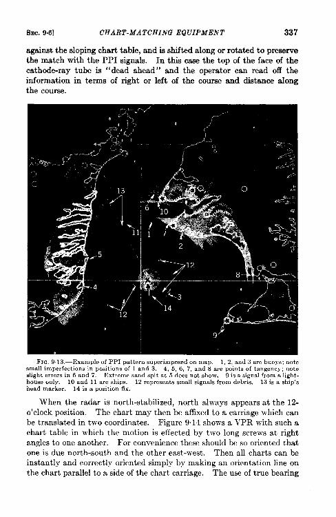
SEC. 9.6] CHART-MA TCHING EQUIPMENT 337
against the sloping chart table, and is shifted along or rotated to preservethe match with the PPI signals. In this case the top of the face of thecathode-rav tube is “dead ahead” and the overator can read oil theinformation in terms of right or left of the course and distance alongthe course.
FIG. 9.13.—Example of PPI pattern superimposed on map. 1, 2, and 3 are buoys; notesmall imperfections in positions of 1 and 3. 4, 5, 6, 7, and S are points of tangency; noteslight errors in 6 and 7, Extreme sand spit at 5 does not show. 9 is a signal from a light-house only. 10 and 11 are ships. 12 represents small signals from debris. 13 is a ship’shead marker. 14 is a position fix.
When the radar is north-stabilized, north always appears at the 12-
o’clock position. The chart may then be affixed to a carriage which can
be translated in two coordinates. Figure 9.14 shows a VPR with such a
chart table in which the motion is effected by two long screws at rightangles to one another. For convenience these should be so oriented thatone is due north-south and the other east-west. Then all charts can beinstantly and correctly oriented simply by making an orientation line on
the chart parallel to a side of the chart carriage. The use of true bearing
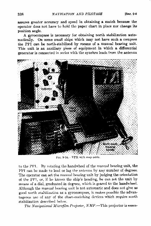
338 NAVIGATION AND PILOTAGE [SEC. 9.6
assurea greater accuracy and speed in obtaining a match becauiw theoperator does not have to hold the paper chart in place nor change itsposition angle.
A gyrocompass is necessary for obtaining north stabilization auto-matically. On some small ships which may not have such a compassthe PPI can be north-stabilized by means of a manual bearing unit.This unit is an auxiliary piece of equipment in which a differentialgenerator is connected in series with the synchro leads from the antenna
to the PPI. By rotating the handwheel of the manual bearing unit, thePPI can be made to lead or lag the antenna by any number of degrees.The operator can set the manual bearing unit by judging the orientationof the PPI, or, if he knows the ship’s heading, he can set the unit bymeans of a dial, graduated in degrees, which is geared to the handwheel.Although the manual bearing unit is not automatic and does not give asgood north stabilization as a gyrocompass, it makes possible the advan-tageous use of any of the chart-matching devices which require northstabilization described below.
The Navigational Microfilm Projector, NMP.—This projector is essen-
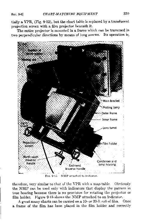
I
SEC. 9.6] CHART-MATCHING EQUIPMENT 339
tially a VPR, (Fig. 9.12), but the chart table is replaced by a translucentprojection screen with a film projector beneath it.
The entire projector is mounted in a frame which can be traversed intwo perpendicular directions by means of long screws. Its operation is,
I
therefore, very similar to that of the VPR with a map table. Obviously
the NMP can be used only with indicators that display the pattern in
true bearing because there is no provision for rotating the projector orfilm holder. Figure 9.15 shows the NMP attached to an indicator.
A great many charts can be carried on a 10- or 20-ft roll of film. Once
a frame of the film has been placed in the film holder and correctly
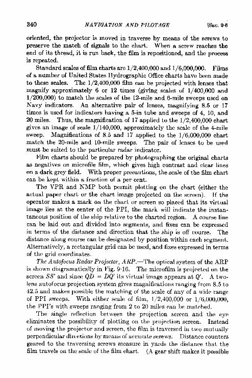
340 NAVIGATION AND PILOTAGE [SEC.9.6
oriented, the projector is moved in traverse by means of the screws topreserve the match of signals to the chart. When a screw reaches theend of its thread, it is run back, the film is repositioned, and the processis repeated.
Standard scales of film charts are 1/2,400,000 and 1/6,000,000. Filmsof a numtxw of United States Hydrographic Office charts have been madeto these scales. The 1/2,400,000 film can be projected with lenses thatmagnify approximately 6 or 12 times (giving scales of 1/400,000 and1/200,000) to match the scales of the 12-mile and 6-mile sweeps used onNavy indicators. An alternative pair of lenses, magnifying 8.5 or 17times is used for indicators having a 5-in tube and sweeps of 4, 10, and20 miles. Thus, the magnification of 17 applied to the 1/2,400,000 chartgives an image of scale 1/140,000, approximately the scale of the 4-milesweep. Magnifications of 8.5 and 17 applied to the 1/6,000,000 chartmatch the 20-rnile and 10-mile sweeps. The pair of lenses to be usedmust be suited to the particular radar indicator.
Film charts should be prepared by photographing the original chartsas negatives on microfile iilm, which gives high contras,t and clear lines
on a dark grey field. With proper precautions, the scale of the film chartcan be kept within a fraction of a per cent.
The VPR and NMP both permit plotting on the chart (either the
actual paper chart or the chart image projected on the screen). If the
operator makes a mark on the chart or screen so placed that its virtual
image lies at the center of the PPI, the mark will indicate the instan-
taneous position of the ship relative to the charted region. A course line
can be laid out and divided into segments, and fixes can be expressed
in terms of the distance and direction that the ship is off course. Thedistance along course can be designated by position within each segment.Alternatively, a rectangular grid can be used, and fixes expressed in terms
of the grid coordinates.
The Autofocus Radar Projector, ARP.—The optical system of the ARP
is shown diagrammatically in Fig. 9.16. The microfilm is projected on the
screen SS’ and since QD = DQ its virtual image appears at Q. A two-lens autofocus projection system gives magnifications ranging from 8.5 to42.5 and makes possible the matching of the scale of any of a wide rangeof PPI sweeps. With either scale of film, 1/2,400,000 or 1/6,000,000,the PPI’s with sweeps ranging from 2 to 20 miles can be matched.
The single reflection bet ween the projection screen and the eyeeliminates the possibility y of plotting on the projection screen. Instead
of moving the projector and screen, the film is traversed in two mutually
perpendicular directions by means of accurate screws. Distance counters
geared to the traversing screws measure in yards the distance that thefilm travels on the scale of the film chart. (A gear shift makes it possible
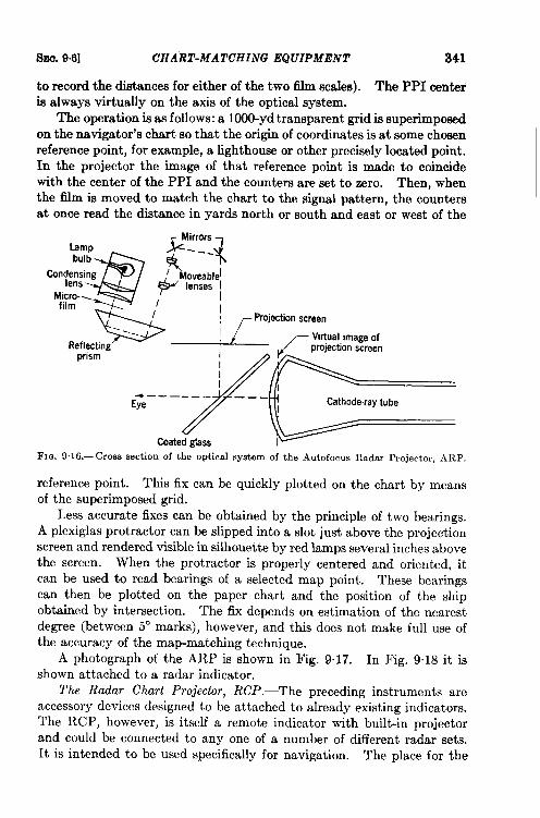
SmJ. 9.6] CHART-MATCHING EQUIPMENT 341
to record the distances for either of the two film scales). The PPI centeris always virtually on the axis of the optical system.
The operation is as follows: a 1000-yd transparent grid is superimposedon the navigator’s chart so that the origin of coordinates is at some chosenreference point, for example, a lighthouse or other precisely located point.In the projector the image of that reference point is made to coincidewith the center of the PPI and the counters are set to zero. Then, whenthe film is moved to match the chart to the signal pattern, the countersat once read the distance in yards north or south and east or west of the
lamp
@
bulb
Conf:::ing ,
Micro-.film <
b
II I
~ Projection screen
,eflec,n> ~/ //-:;&;i:~gw:p,, ,G___yFr
Coated glass
FIG. 9. 16.—Cross section of the optical system of the Autofocus Radar Projector, ARP.
reference point. This fix can be quickly plotted on the chart by meansof the superimposed grid.
Less accurate fixes can be obtained by the principle of two bearings.A plexiglas protractor can be slipped into a slot just above the projectionscreen and rendered visible in silhouette by red lamps several inches abovethe screen. When the protractor is properly centered and oriented, itcan be used to read bearings of a selected map point. These bearingscan then be plotted on the paper chart and the position of the shipobtained by intersection. The fix depends on estimation of the nearestdegree (bet ween 5° marks), however, and this does not make full use ofthe accuracy of the map-matching technique.
A photograph of the ARP is shown in Fig. 9.17. In Fig. 9.18 it isshown attached to a radar indicator.
The Radar Chart Projector, RCP.—The preceding instruments areaccessory devices designed to be attached to already existing indicators.The RCP, however, is itself a remote indicator with built-in projectorand could be connected to any one of a number of different radar sets.It is intended to be used specifically for navigation. The place for the
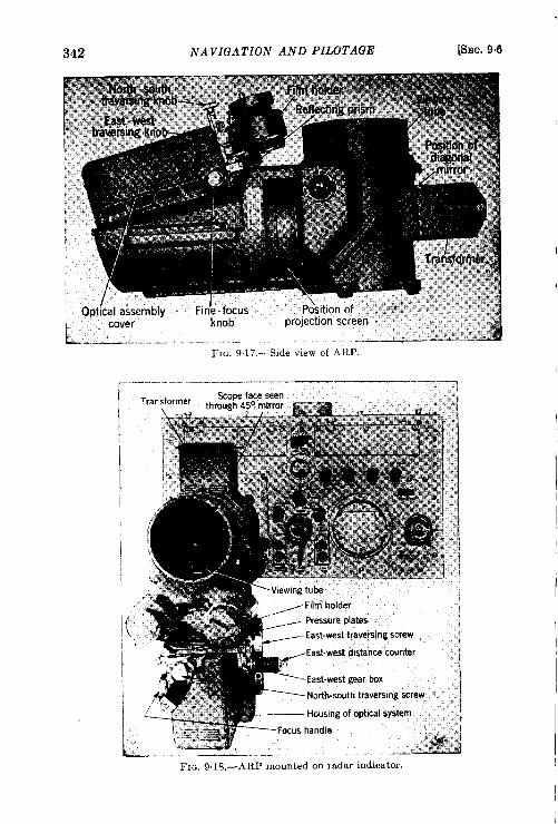
342 NAVIGATION AND PILOTAGE [SEC. 9.6
I
I
FIG. 9.18.—ARP mounted on radar indicator.
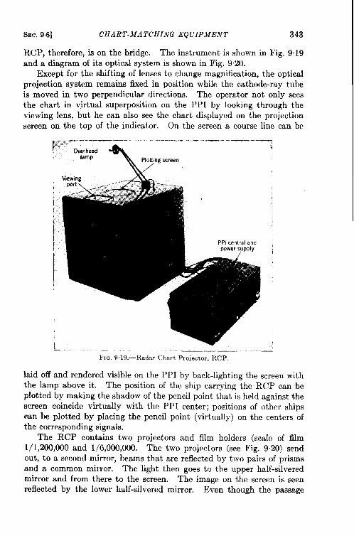
SEC. 9.6] CHART-MATCHING EQUIPMENT 343
RCP, therefore, ison the bridge. Theinstrument isshown in Fig. 9.19
and a diagram of its optical system is shown in Fig. 9.20.
Except forthe shifting of lenses to change magnification, the optical
projection system remains fixed in position while the cathode-ray tube
is moved in two perpendicular directions. The operator not only sees
the chart in virtual superposition on the PPI by looking through the
viewing lens, but he can also see the chart displayed on the projection
screen on the top of the indicator. On the screen a course line can be
F;’:;;a~~’--””
... . . ...._ .-. —.. .—. —~..,
—lamp
I
\
PlOt~ngscreen
ViewinglWrt \ . ---- -~+
1
L,
FIC, 9.19.—Radar Chart Projector, RCP.
laid off and rendered visible on the PPI by back-lighting the screen with
the lamp above it. The position of the ship carrying the RCP can be
plotted by making the shadow of the pencil point that is held against the
screen coincide virtually with the PPI center; positions of other ships
can be plotted by placing the pencil point (virtually) on the centers of
the corresponding signals.
The RCP contains two projectors and film holders (scale of film
1/1,200,000 and 1/6,000,000. The two projectors (see Fig. 9.20) send
out, to a second mirror, beams that are reflected by two pairs of prisms
and a common mirror. The light then goes to the upper half-silveredmirror and from there to the screen. The image on the screen is seenreflected by the lower half-silvered mirror. Even though the passage
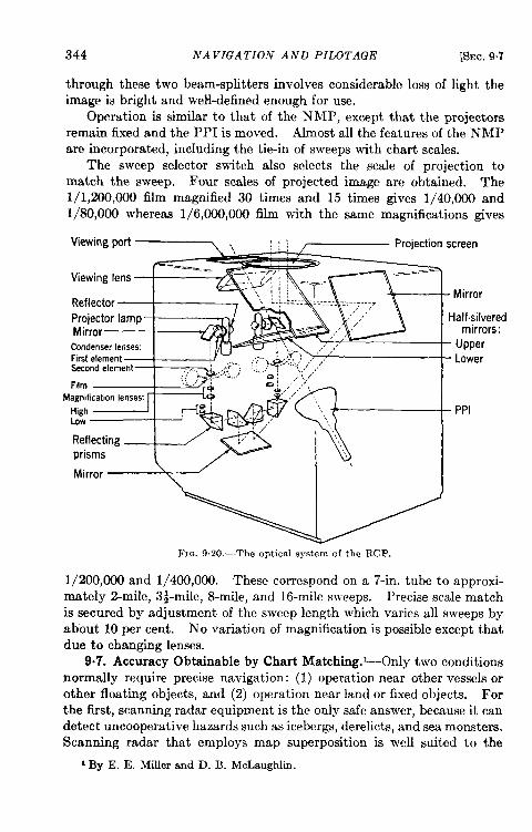
344 NAVIGATION AND PILOTAGE [SEC. 9.7
through these two beam-splitters involves considerable loss of light the
image is bright and weH-defined enough for use.
Operation is similar to that of the NMP, except that the projectorsremain fixed and the PPI is moved. Almost all the features of the NMPare incorporated, including the tie-in of sweeps with chart scales.
The sweep selector switch also selects the scale of projection to
match the sweep. Four scales of projected image are obtained. The
l/1,200,000 film magnified 30 times and 15 times gives 1/40,000 and
1/80,000 whereas 1/6,000,000 film with the same magnifications gives
Viewing port ~.. !:! ~ Projection screen
Viewing lens
Reflector
Projector lamp
Mirror
CondenserlensesFirst elementSecondelement
FilmMagnification lenses
HighLow
Reflecting
iprisms
‘irror>
Mirror
Half.silveredmirrors:
- Upper
- Lower
- PPI
FIG. 9,20.—The optical system of the RCP.
1/200,000 and 1/400,000. These correspond on a 7-in. tube to approxi-mately 2-mile, 3~mile, 8-mile) and 16-mile sweeps. Precise scale matchis secured by adjustment of the sweep length which varies all sweeps byabout 10 per cent. No variation of magnification is possible except thatdue to changing lenses.
9.7. Accuracy Obtainable by Chart Matching. ~Only two conditionsnormally require precise navigation: (1) operation near other vessels orother floating objects, and (2) operation near land or fixed objects. Forthe first, scanning radar equipment is the only safe answer, because it candetect uncooperative hazards such as icebergs, derelicts, and sea monsters.Scanning radar that employs map superposition is well suited to the
I By E. E. Miller and D. B. McLaughlin.
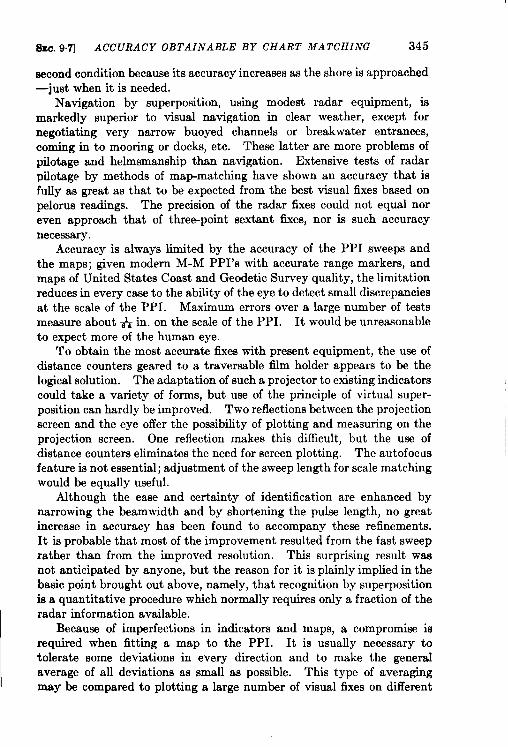
SEC. 9.7] ACCURACY OBTAINABLE BY CHART MATCHING 345
second condition because its accuracy increases as the shore is approached—just when it is needed.
Navigation by superposition, using modest radar equipment, ismarkedly superior to visual navigation in clear weather, except fornegotiating very narrow buoyed channels or breakwater entrances,coming in to mooring or docks, etc. These latter are more problems ofpilotage and helmsmanship than navigation. Extensive tests of radarpilotage by methods of map-matching have shown an accuracy tkat isfully as great as that to be expected from the best visual fixes based onpelorus readings. The precision of the radar fixes could not equal noreven approach that of three-point sextant fixes, nor is such accuracynecessary.
Accuracy is always limited by the accuracy of the PPI sweeps andthe maps; given modern M-M PPI’s with accurate range markers, andmaps of United States Coast and Geodetic Survey quality, the limitationreduces in every case to the ability of the eye to detect smalf discrepanciesat the scale of the PPI. Maximum errors over a large number of testsmeasure about ~ in. on the scale of the PPI. It would be unreasonableto expect more of the human eye.
To obtain the most accurate fixes with present equipment, the use ofdistance counters geared to a traversable film holder appears to be thelogical solution. The adaptation of such a projector to existing indicatorscould take a variety of forms, but use of the principle of virtual super-position can hardly be improved. Two reflections between the projectionscreen and the eye offer the possibility of plotting and measuring on theprojection screen. One reflection makes this difficult, but the use ofdistance counters eliminates the need for screen plotting. The autofocusfeature is not essential; adjustment of the sweep length for scale matchingwould be equally useful.
Although the ease and certainty of identification are enhanced bynarrowing the beamwidth and by shortening the pulse length, no greatincrease in accuracy has been found to accompany these refinements.It is probable that most of the improvement resulted from the fast sweeprather than from the improved resolution. This surprising result wasnot anticipated by anyone, but the reason for it is plainly implied in thebasic point brought out above, namely, that recognition by superpositionis a quantitative procedure which normally requires only a fraction of theradar information available.
Because of imperfections in indicators and maps, a compromise isrequired when fitting a map to the PPI. It is usually necessary totolerate some deviations in every direction and to make the generalaverage of all deviations as small as possible. This type of averagingmay be compared to plotting a large number of visual fixes on different
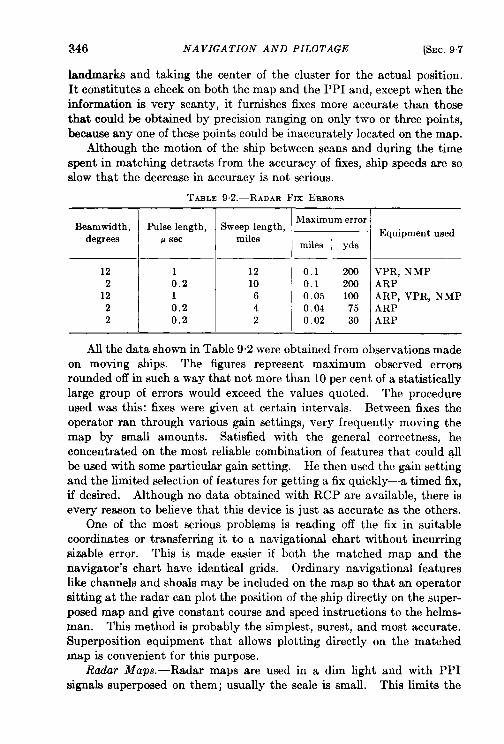
346 NAVIGATION AND PILOTAGE [SEC. 9.7
landmarks and taking the center of the cluster for the actual position.It constitutes a check on both the map and the PPI and, except when theinformation is very scanty, it furnishes fixes more accurate than thosethat could be obtained by precision ranging on only two or three points,because any one of these points could be inaccurately located on the map.
Although the motion of the ship between scans and during the timespent in matching detracts from the accuracy of fixes, ship speeds are soslow that the decrease in accuracy is not serious.
TABLE 9.2.—RADAR Frx EItROItS
Beamwidth,degree8
12
212
22
Pulse length,p sec
10.210.20,2
Sweep length,miles
1210
642
Maximum error
miles
0.10.10.050.040.02
yds
200200100
75
30
Equipment used
VPR, NMPARPARP, VPR, NMPARPARP
AU the data shown in Table 9.2 were obtained from observations madeon moving ships. The figures represent maximum observed errorsrounded off in such a way that not more than 10 per cent of a statisticallylarge group of errors would exceed the values quoted. The procedureused was this: fixes were given at certain intervals. Between fixes theoperator ran through various gain settings, very frequently moving themap by small amounts. Satisfied with the general correctness, heconcentrated on the most reliable combination of features that could allbe used with some particular gain setting. He then used the gain settingand the limited selection of features for getting a fix quickly—a timed fix,if desired. Although no data obtained with RCP are available, there isevery reason to believe that this device is just as accurate as the others.
One of the most serious problems is reading off the fix in suitablecoordinates or transferring it to a navigational chart without incurringsizable error. This is made easier if both the matched map and thenavigator’s chart have identical grids. Ordinary navigational featureslike channels and shoals may be included on the map so that an operatorsitting at the radar can plot the position of the ship directly on the super-posed map and give constant course and speed instructions to the helms-man. This method is probably the simplest, surest, and most accurate.Superposition equipment that allows plotting directly on the matchedmap is convenient for this purpose.
Radar Maps. —Radar maps are used in a dim light and with PPIsignals superposed on them; usually the scale is small. This limits the
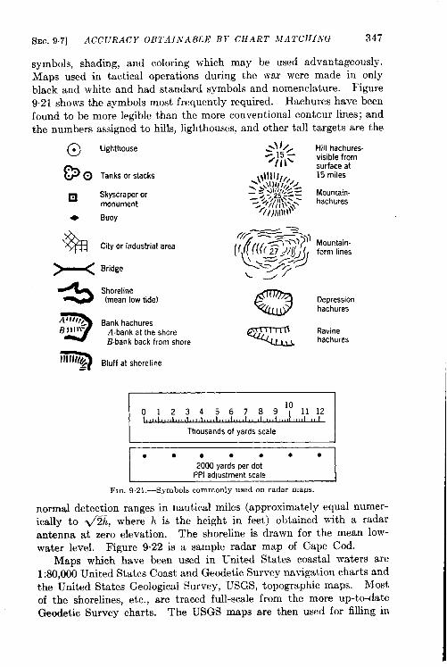
SEC. 9.7] ACCURACY OBTAINABLE BY CHART hfATCHING 347
symbols, shading, and coloring which may be used advantageously.Maps used in tactical operations during the war were made in onlyblack and white and had standard symbols and nomenclature. Figure9.21 shows the symbols most frequently required. Hachures have beenfound to be more legible than the more conventional contcur lines; andthe numbers assigned to hills, lighthouses, and other tall targets are the
@ Lighthouse
~~ Tanks or stacks
❑ Skyscraper ormonument
+ Buoy
% City or industrial area
~ Bridge
43 Shoreline(mean low tide)
3
.41ttf),Bank hachuresBI)lli= A.bank at the shore
Bbank back from shore
7Ifllll/# Bluff at shoreline=~
.! //, Hill hachures.:15-/~, \\ visible from
surface at
\!\l l) ///,, 15 miles- M)(/ /,, /-- >’,!ll //,,4 -—._ + i,:?,<:: Mountain.
-, ‘f// I tN’*= hachures
~///llll\l\
43 Depressionhachures
Ravinehachures
01234567B910
I Thousands of yards scale IJ● e*. e ● *
2000 yards per dotPPI adjustment scale
FIG. 92 1.—Symbols commonly used on radar maps.
normal detection ranges in nautical miles (approximately equal numer-ically to &h, where h is the height in feet) obtained with a radarantenna at zero elevation. The shoreline is drawn for the mean low-water level. Figure 9.22 is a sample radar map of Cape Cod.
Maps which have been used in United States coastal waters are1:80,000 United States Coast and Geodetic Survey navigation charts andthe United States Geological Survey, USGS, topographic maps. Mostof the shorelines, etc., are traced full-scale from the more up-to-dateGeodetic Survey charts. The USGS maps are then used for filling in
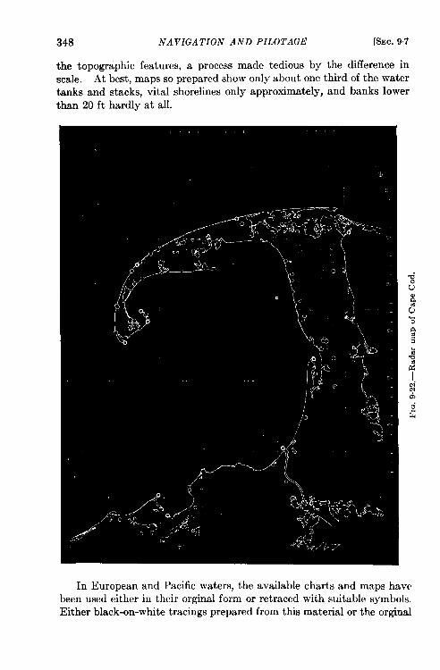
348 NAVIGATION AND PILOTAGE [SEC, 97
the topographic features, a process made tedious by the difference inscale. At best, maps so prepared show only about one third of the watertanks and stacks, vital shorelines only approximately, and banks lower
In European and Pacific waters, the available charts and maps havebeen used either in their orginal form or retraced with suitable symbols.Either black-on-white tracings prepared from this material or the orginal
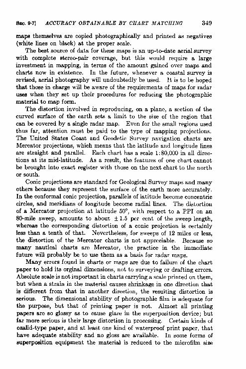
sm. 9.7] ACCURACY OBTAINABLE BY CHART MATCHING 349
maps themselves are copied photographically and printed as negatives(white lines on black) at the proper scale.
The best source of data for these maps is an up-to-date aerial surveywith complete stereo-pair coverage, but this would require a largeinvestment in mapping, in terms of the amount gained over maps andcharts now in existence. In the future, whenever a coastal survey isrevised, aerial photography will undoubtedly be used. It is to be hopedthat those in charge will be aware of the requirements of maps for radaruses when they set up their procedures for reducing the photographicmaterial to map form.
The distortion involved in reproducing, on a plane, a section of thecurved surface of the earth sets a limit to the size of the region thatcan be covered by a single radar map. Even for the small regions usedthus far, attention must be paid to the type of mapping projections.The United States Coast and Geodetic Survey navigation charts areMercator projections, which means that the latitude and longitude limesare straight and parallel. Each chart has a scale 1:80,000 in all direc-tions at its mid-latitude. As a result, the features of one chart cannotbe brought into exact register with those on the next chart to the northor south.
Conic projections are standard for Geological Survey maps and manyothers because they represent the surface of the earth more accurately.In the conformal conic projection, parallels of latitude become concentriccircles, and meridians of longitude become radial lines. The distortionof a Mercator projection at latitude 50°, with respect to a PPI on an8&nile sweep, amounts to about t 1.5 per cent of the sweep length,whereas the corresponding distortion of a conic projection is certainlyleaa than a tenth of that. Nevertheless, for sweeps of 12 miles or less,the distortion of the Mercator charts is not appreciable. Because somany nautical charts are Mercator, the practice in the immediatefuture will probably be to use them as a basis for radar maps.
Many errors found in charts or maps are due to failure of the chartpaper to hold its orginal dimensions, not to surveying or drafting errors.Absolute scale is not important in charts carrying a scale printed on them,but when a strain in the material causes shrinkage in one direction thatis different from that in another direction, the resulting distortion isserious. The dimensional stability of photographic film is adequate forthe purpose, but that of printing paper is not. Almost all printingpapers are so glossy as to cause glare in the superposition device; butfar more serious is their large distortion in processing. Certain kinds ofozalid-type paper, and at least one kind of waterproof print paper, thathave adequate stability and no gloss are available. In some forms ofsuperposition equipment the material is reduced to the microfihn size
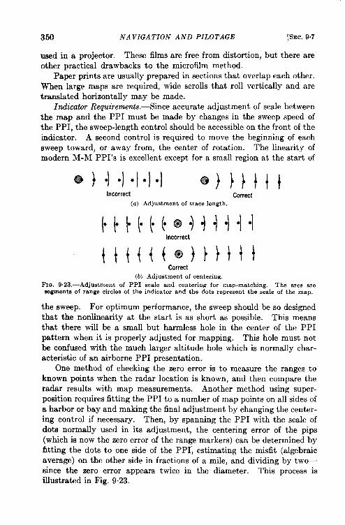
350 NAVIGATION AND PILOTAGE [SEC. 9.7
used in a projector. These films are free from distortion, but there areother practical drawbacks to the microfilm method.
Paper prints are usually prepared in sections that overlap each other.When large maps are required, wide scrolls that roll vertically and aretranslated horizontally may be made.
Indicator Requirements. —Since accurate adjustment of scale bet weenthe map and the PPI must be made by changes in the sweep speed ofthe PPI, the sweep-length control should be accessible on the front of theindicator. A second control is required to move the beginning of eachsweep toward, or away from, the center of rotation. The linearity ofmodern M-M PPI’s is excellent except for a small region at the start of
Incorrect Correct(a) Adjustment of trace length.
H“tm+”)l”l”l”lIncorrect
tt{{{(@)}} litCorrect
(b) Adjustment of centering.Fm. 9.23.—Adj ustment of PPI scale and centering for map-matching. The arcs are.wgments of range circles of the indicator and the dots represent the scale of the map.
the sweep. For optimum performance, the sweep should be so designedthat the nonlinearity at the start is as short as possible. This meansthat there will be a small but harmless hole in the center of the PPIpattern when it is properly adjusted for mapping. This hole must notbe confused with the much larger altitude hole which is normally char-acteristic of an airborne PPI presentation.
One method of checking the zero error is to measure the ranges toknown points when the radar location is known, and then compare theradar results with map measurements. Another method using super-position requires fitting the PPI to a number of map points on all sides ofa harbor or bay and making the final adjustment by changing the center-ing control if necessary. Then, by spanning the PPI with the scale ofdots normally used in its adjustment, the centering error of the pips(which is now the zero error of the range markers) can be determined byfitting the dots to one side of the PPI; estimating the misfit (algebraicaverage) on the other side in fractions of a mile, and dividing by tw~since the zero error appears twice in the diameter. This process isillustrated in Fig. 9.23.
SEC. 9.8] PPI SIMULATIONS 351
The off-center PPI is, unfortunately, rather badly distorted as soonas it is off-centered by more than one tube diameter, A centered M-MPPI, the only known CRT presentation that gives a geometrically precisetwo-dimensional display, is responsible in large measure for the successand accuracy of the superposition technique. North-stabilized PPI’s arefar more convenient to use and are more accurate than relative-bearingtypes. The greatest advantage of the stabilized indicator is that yaw does
not interfere with the measurement of angles between signals. An accu-
rately stabilized PPI would completely eliminate rotation as a degree of
freedom in map-matching, and this in turn would make it possible to
obtain fixes with less radar information on the tube. For this purpose,compasses correct to f 0.5° at all times are desirable because an error of 1°in the orientation of the matched map can easily be detected.
Suggested Improvements.—Greater compactness of matching devicesis desirable. To this end, a PPI built into the same cabinet withthe projector is suggested. The RCP is suitable for a large ship wherethere is room for such remote indicators, but for general use a smallerinstrument is required. A short range sweep (1 or 2 miles) on a cathode-ray tube, which is flat-faced to minimize parallax in superposition andused with the basic VPR, would be a compact and simple arrangement.
Because it is difficult to examine rolls of film in order to find the desiredframe, even on a well-indexed roll, it may be desirable to use a separate
slide for each chart. More space would be needed for storage but
selection of the desired frame could be made more readily than with
a roll of film.
The dead-reckoning tracer or odograph resolves the motion of theship in rectangular coordinates and traces the course on a plotting sheet.‘i’his suggests the use of the odograph data for driving the projectorscrews (or the film-holder screws), thereby keeping the chart matched.To compensate for set and drift, clifferentials could be inserted betweenthe input of odograph data and the projector drive (or film-holder drive)for each coordinate. The differential com~onent due to set and drift ineach coordinate could be determined by the rate of motion required tokeep the chart in match with the PPI. Once determined, this ratecould be constantly fed into the differential and as long as the rateremained constant, the chart would stay in correct match.
9s8. PPI Simulations. -Many attempts have been made to use setsof PPI patterns for navigational purposes. One method of obtainingPPI patterns is to send out an airplane or boat to patrol a desired are~and constantly take PPI photographs. Another method of obtainingPPI patterns in advance is the Radar Planning Device (RPD) technique.The RPD is essentially a point source of light fitted for mounting on s
I By D. B. McLaugbhn.
352 NAVIGATION AND PILOTAGE [SEC. 9.8
relief model of a portion of the surface of the earth. Intended orginally
for determining radar coverage against hostile airplanes, it was found to
be extremely valuable for the prediction of PPI patterns and for the
preparation of simulated PPI pictures.
The point of light is placed on the relief model at a point corresponding
to the position of the radar antenna. Areas that will give signals will be
illuminated and other areas will appear dark. A photograph of the
model thus illuminated will show spots of light in the positions of the
corresponding scope signals. The spread of signals in azimuth can be
simulated by copying the picture on a film mounted on an easel that is
arranged to rotate about the center of the simulation as the exposure is
made. The resulting picture almost perfectly duplicates an actual PPI
photograph obtained with a radar situated at the corresponding point on
the land or water.
Such simulations have been used in navigation tests, principally bytwo methods. In the first, the simulation is mounted in the chartposition on a VPR which is on a table that can be traversed a short
distance in rectangular coordinates. With the simulation centered on the
PPI, the adjustable scales of X and Y are set to zero, and the table istraversed until the simulated and the true PPI’s are superimposed asexactly as possible. The distance of the ship from the position for whichthe simulation was prepared can be read on the scales.
The other method makes use of a rectangular grid superimposed onthe simulation. The signal patterns of the PPI and the simulation aremade to coincide, and the apparent place of the PPI center is read off atonce in terms of the rectangular grid.
The application of the RPD technique is limited. To be of use, itrequires that the course to be followed must have been chosen well inadvance and the simulation prepared from a relief model constructed atthe cost of much time and effort. Such cases did arise during the warwhen invasions were prepared months in advance, but it does not appearfeasible to use these techniques for general navigation except in specialregions-where a narrow channel is to be negotiated, for example.
The greatest value of RPD for navigation would appear to be inbriefing and in the aid it can give the radar operator in showing whattopographic features will give signals and what ones will not. Thiswould greatly facilitate recognition of terrain features and identificationof signals. If the simulations are used in the VPR, however, they shouldcertainly be a part of the VPR chart. As always, the chart sho~d havethe shoreline and the more prominent topographic features marked bytheir conventional signs, and the simulated scope pattern should merelysupplement these chart features. In tests of navigation, by matchingsimulated PPI’s to real signal patterns, the fixes did not attain the degree
SEW. 9.8] PPI SIMULATIONS 353
of accuracy given by the simple chart-matching procedure that makesuse chiefly of a chart on which the shoreline is by far the most importantfeature.
Both PPI photographs and RPD simulations are sensitive to suchfactors as variation in atmospheric refraction whereas the accuracy ofsimple map superposition is not affected. Indeed, the map-superpositionmethod benefits by supernormal propagation in that it is able to obtainfixes at a greater distance from shore.
BIBLIOGRAPHY
PREPARATION OF MAPS
“Preparation of Maps for Use with the VPR,” RL Group 102 Report.
MAP-MATCHING TECHNIQUES
“Use of the VPR for Matching a Map to the PPI,” RL Group 102 Report.Miller, E. E, and D. B. McLaughlin, “Precise Navigation by Means of a Radar
Map Superposed on the PPI,” RL Report No. 503, April 7, 1944.“ A .Manual of Radar Recognition, ” Seventh Progress Board Report NALOC to the
Chairman NDRC, May 12, 1944.
VIRTUAL PPI REFLECTOSCOPE, VPR
“ Instruction Manual for VPR,” Radiation Laboratory, M. I. T., November 1943.
NAVIGATIONAL MICROFILM PROJECTOR, NMP
Fourth Progress Report NALOC to the Chairman NDRC, Feb. 15, 1945.
AUTOFOCUS RADAR PROJECTOR, ARP
McLaughlin, D, B. and C, A. Smith, “A Microfilm Chart Projector for Radar Naviga-
tion,” RL Report No. 658, January 23, 1945.
RADAR CHART PROJECTOR, RCP
McLaughlin, D. B. and C. A. Smith, “The Radar Chart Projector,” RL Report No.926, 1945.
RADAR PLANNING DEVICE, RPD
“ RPD Radar Planning Device (16-c-23 ),” Conavaer No. 30-160R-28, November,1944.
“ RPD in Surface Navigation,” Aer SD-112 FLR Special Devices, Bulletin No. Ds 8.“B-scope Simulator, ” Device No. l& G2~u, Aer SD-112 FLR Special Devices
Bulletin No. Ds. 9.
MANUAL BEARING UNIT
Smith, C. A., “ Preliminary Instructions for the Manual Bearing Unit,” RL ReportNo, M-192, January 9, 1945.
A
BY J. P.
CHAPTER 10
SHIPBORNE NAVIGATIONAL RADAR
NASH, R. M. EMSERSON,AND R. E. MEACIHER
The problem of designing a shipborne navigational radar is influencedstrongly by several factors beyond the designer’s direct control. Theseare the low altitude of both the antenna and targets, the efiect of thecurvature of the earth; the interference between direct beams and thosereflected from the water, and atmospheric refraction. It is fitting,therefore, to begin this chapter with a discussion ‘of radar propagationover water.
10.1. Radar Propagation over Water.~The propagation of radarwaves over the curved conducting earth is complicated, although thereis little reflection of microwave radiation by the ground, and the antennapattern over land is usually a clean-cut lobe. Over water (and over landwith long-wave radar) the situation is more complicated. The problemcan be studied as a problem in diffraction by careful analysis with ray-tracing methods near the radar set and in the region below the horizon.A detailed discussion is found in Propagation oj Short Radio Waves andRadar System Enginea”ng, Vols. 13 and 1, Radiation Laboratory Series.Only enough of the theory to give the reader a feeling for what goes onoutside the shipborne radar set is presented here so that he may under-stand more fully the nature of the problems that arise and how properradar design can solve them.
Before studying the contribution of the surface of the ocean to thebehavior of radar waves after they leave the antenna, the so-called“free-space” case, in which the radar set and its target are supposed tobe in an otherwise empty space, should be reexamined. In Sec. 1.3 it waspointed out that in free space the dependence of range upon other factorscan be expressed by the equation
‘m ‘(%%)”‘“’’(%lw (1)
It is apparent that the free-space range varies inversely as the squareroot of the wavelength if all other quantities in Eq. (1) are held fixed.That is, in two radar sets for which all quantities of Eq. (1) except x
1J. P. Nash.3s4
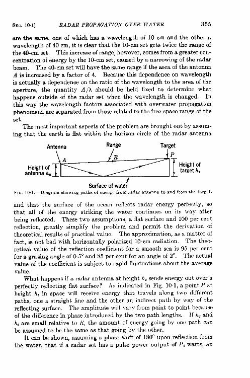
SEC. 10.1] RADAR PROPAGATZOIV OVER WATER 355
are the same, one of which has a wavelength of 10 cm and the other awavelength of 40 cm, it is clear that the 10-cm set gets twice the range ofthe 40-cm set. This increase of range, however, comes from a greater con-centration of energy by the 10-cm set, caused by a narrowing of the radarbeam. The 40-cm set will have the same range if the area of the antennaA is increased by a factor of 4. Because this dependence on wavelengthis actually a dependence on the ratio of the wavelength to the area of theaperture, the quantity A/A should be held fixed to determine whathappens outside of the radar set when the wavelength is changed. Inthis way the wavelength factors associated with overwater propagationphenomena are separated from those related to the free-space range of theset.
The most important aspects of the problem are brought out by assum-ing that the earth is flat within the horizon circle of the radar antenna
‘n~e~’’’””Height ofantenna h=
Surface of wate~FIQ. 10,1,—Diagram showing paths of energy from radar antenna to and from the target.
and that the surface of the ocean reflects radar energy perfectly, sothat all of the energy striking the water continues on its way afterbeing reflected. These two assumptions, a flat surface and 100 per centreflection, greatly simplify the problem and permit the derivation oftheoretical results of practical value. The approximation, as a matter offact, is not bad with horizontally polarized 10-cm radiation. The theo-retical value of the reflection coefficient for a smooth sea is 95 per centfor a grazing angle of 0.5° and 85 per cent for an angle of 2°. The actualvalue of the coefficient is subject to rapid fluctuations about the averagevalue.
What happens if a radar antenna at height h. sends energy out over aperfectly reflecting flat surface ? As indicated in Fig. 10.1, a point P at
height h, in space will receive energy that travels along two differentpaths, one a straight line and the other an indirect path by way of thereflecting surface. The amplitude will vary from point to point becauseof the difference in phase introduced by the two path lengths. If h. andh’ are small relative to R, the amount of energy going by one path canbe assumed to be the same as that going by the other.
It can be shown, assuming a phase shift of 180° upon reflection fromthe water, that if a radar set has a pulse power output of P: watts, an
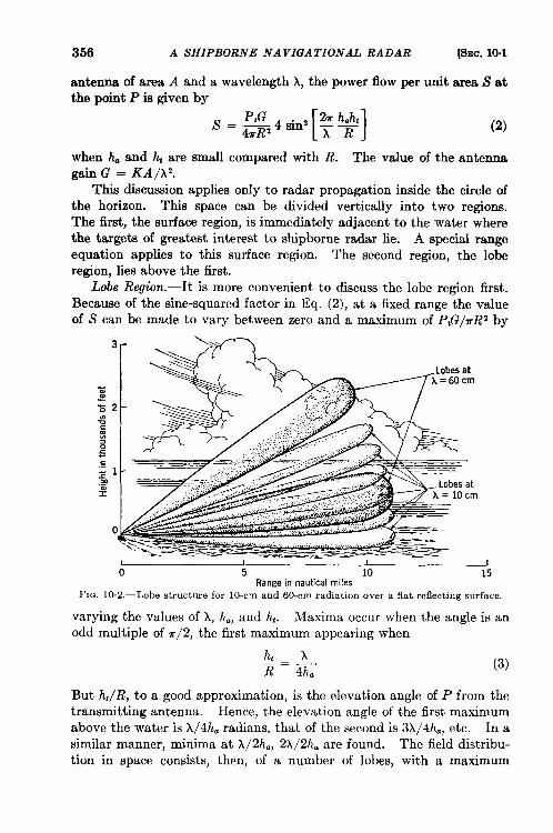
356 A SHIPBORNE NAVIGATIONAL RADAR [SEC. 10.1
antenna of area A and a wavelength X, the power flow per unit area S atthe point P is given by
(2)
when h. and h~are small compared with R. The value of the antennagain G = KA/h2.
This discussion applies only to radar propagation inside the circle ofthe horizon. This space can be divided vertically into two regions.The first, the surface region, is immediately adjacent to the water wherethe targets of greatest interest to shipborne radar lie. A special rangeequation applies to this surface region. The second region, the loberegion, lies above the fist.
Lobe Region.—It is more convenient to discuss the lobe region first.Because of the sine-squared factor in Eq. (2), at a fixed range the valueof S can be made to vary between zero and a maximum of P~G/rRZ by
varying the values of A, h., and ht. Maxima occur when the angle is anodd multiple of 7r/2, the first maximum appearing when
(3)
But h,/R, to a good approximation, is the elevation angle of P from the
transmitting antenna. Hence, the elevation angle of the first maximum
above the water is A/4h. radians, that of the second is 3A/4h., etc. In asimilar manner, minima at A/2ha, 2A/2h. are found. The field distribu-
tion in space consists, then, of a number of lobes, with a maximum
SEC. 10.1] RADAR PROPAGATION OVER WATER 357
intensity along the center line of each lobe. The lobes are separated byregions of low intensity. If the two assumptions above were correct, theintensity would be zero, theoretically, midway between two adjacentlobe maxima.
F@re 10.2 shows the lobe structure above a flat reflecting surface fortwo radar sets operating on wavelengths of 10 and 60 cm and withantennas 30 ft high. A good 10-cm radar set with a pulse power outputof about 20 kw and an antenna area of about 2 ftz should detect a largeairplane along these contours. The surface region for 10 cm is indicated.It is important to notice that the lobe structure is much finer for the 10-cmthan for the 60-cm radiation and that there are six times as many lobesat the shorter wavelengths. They also increase in number as the antennais raised.
&@ace Region.—The surjace region lies beneath the lowest lobe. Itis more important to the navigator because its position determines the
radar coverage near the water. From Eq. (3), which defines the position
of the lowest lobe, it is clear that targets are in or above the lowest lobe if
(4)
and are in the surface region if R is greater than this value. For targets
that are at a reasonable distance the angle of Eq. (2) is small and the sinemay be replaced by the angle. If ha = 30 ft, h, = 20 ft, and
A=lOcm=+ft,
the surface region is more than 2400 yd away. If there is a pointtarget of radar cross section u at P (Fig. 10.1) and if the minimum
detectable signal of the radar set is Srninlit can then be shown from Eq.(2) that
R=2’(&)’(#RY’ (5)
This equation has been called the ‘‘ eighth-po~ver range formula” because
range varies as the eighth root of the transmitted or received power
rather than as the fourth root in free space [see ~q. (l)]. Equation (5)
is valid only for a point target in the surface region (a region often
referred to as the “eighth-power region”).
As an example of the use of Eq. (5), let us calculate the maximum range
at which a small cabin cruiser can be detected with a radar set mounted
40 ft above the water, assuming that the cruiser can be treated as a point
target. Let us assume that P, = 20 kw at 3 cm, that P,/S!~,m= 2 X 10’5,and A is 1.3 ft2 or 0.8 ft2 when an efficiency factor 0.6 is used. Areasonable value for the radar cross sect ion u of the target is 70 ft‘, and
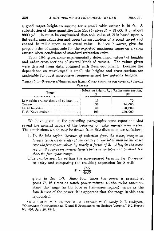
358 A 5HIPBORNE NAVIGATIONAL RADAR [SEC. 10.1
a good target height to assume for a small cabin cruiser is 10 ft. A
substitution of these quantities into Eq. (5) gives R = 27,000 ft or about9000 yd. It must be emphasized that this value of R is based upon aflat-earth approximation and upon the assumption of a point target andcannot be relied upon as an exact value. It does, however, give theproper order of magnitude for the expected maximum range on a cabincruiser when conditions of standard refraction exist.
Table 10.1 gives some experimentally determined values’ of heightsand radar cross sections of several kinds of vessels. The values givenwere derived from data obtained with 3-cm equipment. Because thedependence on wavelength is small, the heights and cross sections areapplicable for most microwave frequencies and low antenna heights.
TABLE1O.1.—EFFECTIVEHEIGETSAND RADAR CROSS SECTIONS FOR SEVERAL SURFACE
VESSELS
TargetEffective height, h,, Radar cross section,
ft ft 2
Low cabin cruiser about 40 ft long. 10 70Tanker . . . . . 30 24,000Large freighter . . . 60 SO,oooU. S. Navy cruiser . . . . . . . . . . . . . 100 150,000
We have given in the preceding paragraphs some equations that
reveal the general nature of the behavior of radar energy over water.
The conclusions which may be drawn from this discussion are as follows:
1. In the lobe region, because oj rejection from the water, ranges ontargets (such as aircrajt) at the centers oj the lobes may be increasedover the ji-ee-space values by nearly a jactor oj 2. Also, in the sameregion, the range on similar targets between the lobes will be much lessthan the free-space range.
This can be seen by setting the sine-squared term in Eq. (2) equalto unity and comparing the resulting expression for S with
P==4TR2
given in Sec. 1.3. Since four times the power is present atpoint P, 16 times as much power returns to the radar antenna.Since the range (in the lobe or free-space region) varies as thefourth root of the power, it is apparent that the range in this caseis doubled.
10. J. Baltzer, V. A. Counter, W. M. Fairbank, W. O. Gordy, E. L. Hudspeth,“Overwater Observationsat X and S Frequencieson SurfaceTargets,” RL ReportNo. 401, July 26, 1943.
SEC. 10-11 RADAR PROPAGATION OVER WATER 359
In actual practice the roundness of the earth and the imperfect con-ductivity and roughness of sea water make the range increase lessthan a factor of 2 for microwaves, but ranges approaching thedoubled value have been observed. Also, since there is no way ofgetting extra power for nothing, the range on an airplane midwaybetween two lobes, although theoretically zero, is actually verygreatly reduced from the free-space value.
2. Other factors being equal, the best radar coverage over water is given byshort waveZcn@hs. This is immediately apparent from Eq. (3)because the elevation angle of the lowest lobe varies directly withthe wavelength. Figure 10.2 shows this clearly. A quantitativeidea of the advantage of short wavelengths is obtainable from Eq.(5). The fourth-root term involving A/x is ignored since it wasassumed that this factor was held constant in comparing one setwith another. From the square-root factor (hah,/A))*, it is seen
that the range in the surface region vam”esinversely as the square rootof the wavekmgth. This means that if the free-space ranges of alo-cm and a 40-cm radar were equal, the 10-cm system would havetwice the range of a 40-cm radar set on targets in the surface region.
Equation (5) also shows that the range in the surface region is directlyproportional to the square root of the product of haand h,. Sincethe height of the target is beyond the control of the radar designerhe must content himself by mounting the radar antenna as highas is practical. An antenna mounted at a height of 40 ft will givetwice the surface range of the same antenna when only 10 ft abovethe water.
For point targets like corner reflectors, the square-root relationshipbet ween R and h, has been confirmed experimentally. For largertargets like ships an “effective height” must be used to calculateranges. Its determination would be relatively simple if it werenot for the presence of the unknown value of u which also appearsin Eq. (5). When a target moves out of the lowest lobe and intothe surface region, the returned energy no longer obeys an inversefourth-power law, but follows an inverse eighth power, as given byEq. (5). Hence, it is possible to determine experimentally therange at this point of transition and to calculate an effective heightfrom Eq. (4); u can then be found from Eq. (5). The values givenin Table 10.1 were obtained in this way.
3. Intensity of energy in the surjace region is low. Since range variesas the eighth root of the output power for targets in the surfaceregion, this power must theoretically be increased 256 times inorder to double the range. In practice the figure may even be
A SHIPBORNE NAVIGATIONAL RADAR [SEC. 10.1
higher than this. The free-space factor for doubling the range isonly 16. This means that maximum ranges in the surface regionare much lower than in free space for the same power and targetsize. It also means that for targets in the surface region, changesin power have a much smaller effect upon range than they do infree space.
Nonstandard Propagation.—The above discussion of the structure ofthe composite radiation pattern caused by the interference between thedirect and reflected beams has been based on the assumption of a flatearth and 100 per cent reflection from the water. In Sec. 1.4 it wasstated that the distance to the radar horizon for microwave energy isnormally 14 per cent greater than the geometrical value. The energy issometimes refracted nonuniformly, however, in such a way that surfacedetection ranges many times greater than those ordinarily achievedresult. It is also possible for the reverse to happen, in which event rangesof less than the expected values will be obtained. Since decreases inrange occur much less frequently than increases, a prolonged period ofsubstandard ranges usually means that the radar set is not performing asit should. Extensive studies have been made of the causes of nonstand-ard propagation, and a more detailed discussion of the subject will befound in Vol. 13, Chaps. 3 and 4, of this series.
The atmospheric conditions that cause nonstandard propagationusually occur within a few hundred feet of the surface of the earth,although higher layers are sometimes of considerable importance. Unlessthe radar energy is directed almost parallel to such a layer, it is affectedvery little. Consequently, airborne radar sets are not affected by non-standard propagation phenomena unless the aircraft are flying very low.Aboard ship, these effects are important because the antennas are low.It is possible, by means of temperature and humidity measurements overa range of heights, to determine whether or not a trapping conditionexists at a given time, but the problem is so complicated that reliableprediction of periods of nonstandard propagation is not yet possible.
Low-level ducts that guide microwave energy in such a way as to
permit the detection of objects at great distances below the horizon are acommon occurrence. Under some conditions, the ranges for detection of
surface targets can be extended by reducing the height of the radar
antenna, but these low ducts do not occur often enough to warrant mov-ing the antenna down. In periods when the duct does not exist or isvery weak, lowering the antenna causes a loss in range.
Very strong trapping of the shortest wavelengths in surface ducts islikely to occur only near large land masses. The longer wavelengths maybe affected similarly both near to and far from land because of elevatedregions of nonstandard refraction as well as surface ducts.
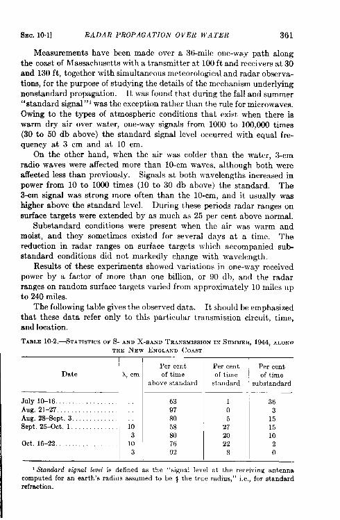
SEC. 10.1] RADAR PROPAGATION OVER WATER 361
Measurements have been made over a 36-mile one-way path alongthe coast of Massachusetts with a transmitter at 100 ft and receivers at 30and 130 ft, together with simultaneous meteorological andradarobserva-tions, for the purpose of studying the details of the mechanism underlyingnonstandard propagation. It was found that during the fall and summer“standard signal” 1was the exception rather than the rule for microwaves.Owing to the types of atmospheric conditions that exist when there iswarm dry air over water, one-way signals from 1000 to 100,000 times(30 to 50 db above) the standard signal level occurred with equal fre-quency at 3 cm and at 10 cm.
On the other hand, when the air was colder than the water, 3-cmradio waves were affected more than 10-cm waves, although both wereaffected less than previously. Signals at both wavelengths increased inpower from 10 to 1000 times (10 to 30 db above) the standard. The3-cm signal was strong more often than the 10-cm, and it usually washigher above the standard level. During these periods radar ranges onsurface targets were extended by as much as 25 per cent above normal.
Substandard conditions were present when the air was warm andmoist, and they sometimes existed for several days at a time. Thereduction in radar ranges on surface targets which accompanied substandard conditions did not markedly change with wavelength.
Results of these experiments showed variations in one-way receivedpower by a factor of more than one billion, or 90 db, and the radarranges on random surface targets varied from approximately 10 miles upto 240 miles.
The following table gives the observed data. It should be emphasizedthat these data refer only to this particular transmission circuit, time,and location.
TABLE1O.2.-STATIST1CSOFS- ANDX-BANDTRANSWSS1ONINSUMMER,1944,ALONCTEE NEW ENGLAND COAST
IDate i, cm
July lo-16 . . . . . . . . . . . . . . . . .Aug. 21-27 . . . . . . . . . . . . . . . . . ::Aug. 28-Sept. 3 . . . . . . . . . . . .Sept. 25-Ott. l . . . . . . . . . . . . . 10
3Ott. 16-22 . . . . . . . . . . . .._ 10
3
Per centof time
above standard
63
97
80
58
8076
92
Per centof time
standard
105
272022
8
Per centof time
ubstandard
363
151510
20
1Standard signal level is defined as the “signal level at the receiving antennacomputed for an earth’s radius assumed to be # the true radius, ” i.e., for standardrefraction.
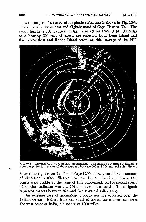
am?. 10.2] SHIPBORNE NAVIGATIONAL RADAR 363
In general, 3-cm energy from low antennas is more likely to be trappedand guided along the surface than is 10-cm radiation. Other thingsIx+ng equal, then, a 3-cm set is likely to give better surface coverage thana lo-cm set when its antenna is mounted at the same height, for inaddition to the low-cover advantage obtained from the shorter wave-length under standard propagation conditions, there is the added pos-sibtilty of radiation trapping.
Propagation over land is also affected by nonstandard refraction,but in this case the effects are even more complicated. Periods of non-standard refraction usually occur at night; one of the principal results isan increase in ground clutter caused by guiding of energy near the surfaceof the earth.
It has been suggested that there may be refraction effects that willcause the rays to bend appreciably in the horizontal plane, giving rise topossibly erroneous bearing information. The small amount of informa-tion now available (obtained over land, which may possibly exaggeratethe effect) indicates that an extreme value for such bending is about 0.1°.It is, at any rate, too small to measure very accurately. Bending in thevertical plane may be somewhat larger, according to the small amountof information available.
10.2. General Specifications of a Shipbome Navigational Radar.’—Although the basic electronic circuits in a shipborne radar may beidentical with those used in airborne or ground radars, the operatingconditions and requirements peculiar to shipborne equipment are prob-ably more severe. Ship equipment must operate dependably forseveral weeks at a time. It must be designed to withstand continuous,vibration and high humidity coupled with the highly corrosive action ofsalt air, and to operate in spite of large voltage fluctuations in the powersupply of the ship.
The simplest radars are designed as a single unit. Any departurefrom this construction increases the complexity of the system. On theother band, if a number of units are used, only the indicators need beinstalled on the bridge or at other already crowded stations. A surface-search radar may be conveniently designed in four units: an antennaassembly, a transmitter-receiver or r-f package, an indicator and controlpackage, and a power-supply package.
Before a radar set is designed for use on a ship it must be decidedwhether the set is to interrogate beacons. If beacons are to be used,either with or without interrogation coding, they and the radar set mustbe designed together as components of a more comprehensive system.Beacons designed as an afterthought have never been completely satis-factory. It must be decided, in particular, whether the radar traffic is
1Sections10.2to end of chapterby R. M. Embereonand R. E. Meagher.
364 A SHIPBORNE NAVIGATIONAL RADAR [SEC. 10.8
likely to be so dense that interrogation coding for beacons will be needed;the design of the modulator will depend on the decision. Also, thedesirability of rapid switching between reception of beacons and echoes,and of automatic control of the tuning for reception of beacons must bejudged, and the receiver designed accordingly. The special requirementsto be incorporated into a radar that is to operate with beacons havebeen given in Sec. 9“3. AN/APS-10 was designed and built to operatewith beacons. It is not necessary to discuss this aspect of the problemexplicitly here since it is discussed in Sec. 6.3.
The general specifications are as follows:Antenna: Horizontal beamwidth 2° or less; vertical beamwidth 15°.
In the horizontal plane, the secondary side lobes less than ~ of thecentral beam intensity at all angles more than three beamwidths (6°)from the axis. Scan rate approximately 6 rpm.
Transmitter: at 3.25 cm, with 50-kw pulse power and +Psec pulses;repetition rate 1000 cps.
Receiver: noise figure no more than 15 db below the value the~retically possible; 6- to 8-Me/see bandwidth with a 30-Mc/sec i-f ampli-fier. Video channels in the receiver and indicator should be at least6 Me/see wide.
Indicator: 12-in. PPI, with 2-, 10-, 20-, and 40-rnile sweeps. Angularaccuracy to be better than 2°, with a lag of less than 0.5° and a “jitter”of lees than 0.05°. Accuracy of range markers to be better than 1.5 percent of the indicated amount.
10.3. Antenna Assembly.—The most common radiation pattern of aradar antenna is a beam widened in one direction rather than a symmet-rical pencil beam with a circular cross section. Shipborne radar intendedsolely for navigation and pilotage ideally should have the sharpestpossible pencil beam to provide the greatest resolution in azimuth and themaximum detection ranges. The relationship between resolution andbeamwidth is illustrated by Fig. 10”4. The rolling and pitching of aship, however, make the utilization of a sharp beam impractical. Sta-btization problems are discussed in connection with airborne radar inSec. 5.4 and in more detail elsewherein this series.’ Aspects of the prob-lem particularly pertinent to shipborne radars are briefly treated here.
Deck-tilt Errors.—The use of an unstabilized fanned radar beam canintroduce appreciable azimuth or deck-tilt errors for certain relativebearings. This is easily understood if one considers first a radar antennaturned to a tar~et located at 270° relative bearing, i.e., on the port beam.Let us assume ~hat the ship does not pitch. Then, as the ship rolls thevertically fanned beam will sweep up and down across the target, but ~
1 Radar System En@neering, Vol. 1, Chap. 9; Radar Scanners and Radomea, Vol. ~26, ChapE.4 and 7. J
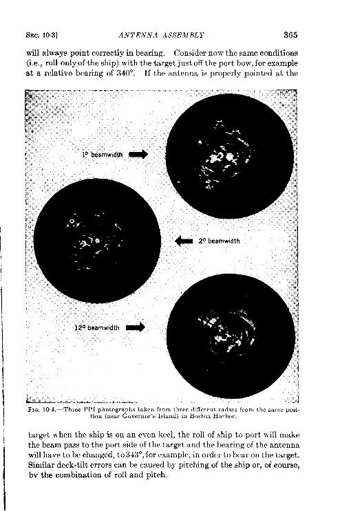
SEC. 103] ANTENNA ASSEMBLY 365
will always point correctly in bearing. Consider now the same conditions(i.e., roll only of the ship) with the target j ust off the port bow, for exampleat a relative bearing of 340”. If the antenna is properly pointed at the
FIG. 10.4.—Three PPI photographs taken from three different radars from the same posi-tion (near Governor’s Island) in Boston Harbor.
target w-hen the ship is on an even keel, the roll of ship to port will make
the beam pass to the port side of the target and the bearing of the antenna
will have to be changed, to 343°, for example, in order to bear on the target.
Similar deck-tilt errors can be caused by Pitching of the ship or, of course,
bv the combination of roll and pitch.
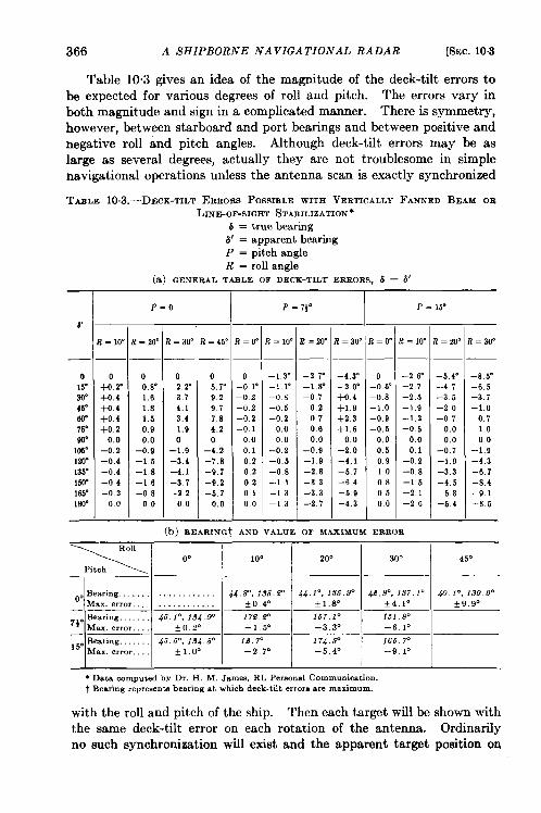
366 A SHIPBORNE NAVIGATIONAL RADAR [SEC. 10.3
Table 10.3 gives an idea of the magnitude of the deck-tilt errors tobe expected for various degrees of roll and pitch. The errors vary inboth magnitude and sign in a complicated manner. There is symmetry,however, between starboard and port bearings and between positive andnegative roll and pitch angles. Although deck-tilt errors may be aslarge as several degrees, actually they are not troublesome in simplenavigational operations unless the antenna scan is exactly synchronized
TAZLE 1O.3.—DECK-TILTERRORSPOSSIBLE WITH VERTICALLY FANNED BEAM OR
LINE-OF-SIGHT STABILIZATION”
6 = true bearing~’ = apparent bearingP = pitch angleR = roll angle
(a) GENERAL TABLE OF DECK-TILT ERRORS, 6 – 6’
#
o15”30”45”60”76”w163”120”135”LW165”180”
—
0+0.2”+0.4+0.4+0.4+0 20.0
–0.2–0.4–o 4–o 4–o 200
P=o
!= 20”
00. 8“1.61.81.50.90.0
–0.9–1,5–1 8–1 6–O 800
z = 30”
02.2”3.74.13.41.90
-1.9-3.4–4.1–3.7–2 200
!=4s
o5.r9.29,7784.20
–4.2–7.8–9 7–9 2–5.70.0
t=o’
o-0.1’–0.2-0.2–0,2-0.1000.10.202020100
t = 10”
–1 3“–1.1”–O.s–o 5–0.20.000
-0.2–0.5–0.8–1 1–1 3–1 3
t= 20’
–2.7”–l,s”–o 70.2070.60.0
–0.9-1.9-2.8-33-33-27
–4 3“–2 0“+0.4+1 9+2.3+1.60.0
–2.0–4.1–5 7–6 4–5 9–4.3
i!=o
o-0.5’–0.8–1 o-09–0.50.00.50.91,00,8050.0
t = lo-
–2 6“–2.7–2.5–1.9–1,2–o 50.00.1
–0.2–0.8–1 5–2.1–2,6
(b) FIEARINGt AND VALUE OF MAXIMUM ERROR
‘.. R
–5 4“–4 7–3.5–2 o–o 7
0.00.0
-0.7–1 9–3 3–4.5–5.3–5.4
? = 30”
–8 5“–6,5–3.7–1.00.71,000
–1.9–4.3–6,7–8.4–9.1–8 5
P,* 00 10” 20” 30° 45”
~.Bearing 44.8=, 136.9” 44,1°,136.9” 4$?.9°,1.57.1° 40.10,1$9,9”M%.x.errm *O 4. +1.8° +4.10
—+9,90
. Bearing. . . . . . . 46.1”, 134.9”‘~ Max. error. .,
172..@ 167.1” 1619“+0.20 –1,5° –3 3“
—–6.1”
~~.Bearing. . . . . 46.6”, 134.6” 1.2.P 174.6° 166 7=Max. error. *1.0” –2,7” –5.4” –9.1”
* Data computedby Dr. K M. James, RL Permnal Communication.t Bearing repreaentabearing at which deck-tilt errors are maximum.
with the roll and pitch of the ship. Then each target will be shown with
the same deck-tilt error on each rotation of the antenna. Ordinarily
no such synchronization will exist and the apparent target position orI
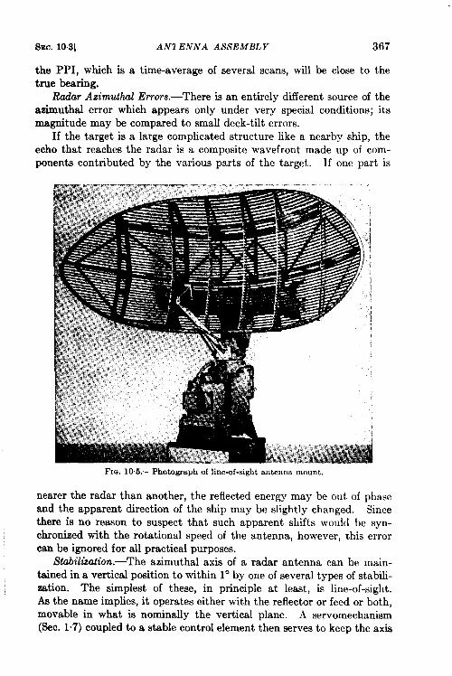
SEC. 10.3] AN1 ENNA ASSEMBLY 367
the PPI, which is a time-average of several scans, will be close to thetrue bearing.
Radar Azin@uzl Errors. —There is an entirely different source of theazimuthal error which appears only under very special conditions; itsmagnitude may be compared to small deck-tilt errors.
If the target is a large complicated structure like a nearby ship, theecho that reaches the radar is a composite wavefront made up of com-ponents contributed by the various parts of the target. If one part is
FIG. 10.5.—Photograph of line-of-sight antenna mount,
nearer the radar than another, the reflected energy may be out of phaseand the apparent direction of the ship may be slightly changed. Sincethere is no reason to suspect that such apparent shifts would be syn-chronized with the rotational speed of the antenna, however, this errorcan be ignored for all practical purposes.
Stabilization.-The azimuthal axis of a radar antenna can be main-tained in a vertical position to within 1° by one of several types of stabili-zation. The simplest of these, in principle at least, is line-of-sight.As the name implies, it operates either with the reflector or feed or both,movable in what is nominally the vertical plane. A servomechanism(SeC. 1“7) coupled to a stable control element then serves to keep the axis
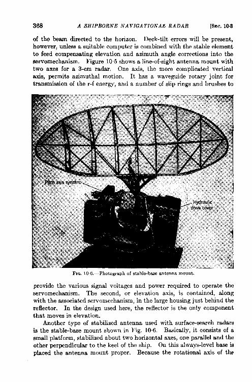
368 A SHIPBORNE NA VIGA TIONAE RADAR [SEC.10.8
of the beam directed to the horizon. Deck-tilt errors will be present,however, unless a suitable computer is combined with the stable elementto feed compensating elevation and azimuth angle corrections into theservomechanism. Figure 105 shows a line-of-sight antenna mount withtwo axes for a 3-cm radar. One axis, the more complicated verticalaxis, permits azimuthal motion. It has a waveguide rotary joint fortransmission of the r-f energy, and a number of slip rings and brushes to
FIG. 106.-Photograph of stable-base antenna mount.
provide the various signal voltages and power required to operate theservomechanism. The second, or elevation axis, is contained, alongwit h the associated servomechanism, in the large housing just behind thereflector. In the design used here, the reflector is the only componentthat moves in elevation.
Another type of stabilized antenna used with surface-search radarsis the stable-base mount shown in Fig. 10”6. Basically, it consists of asmall platform, stabilized about two horizontal axes, one parallel and theother perpendicular to the keel of the ship. On this always-level base is
placed the antenna mount proper. Because the rotational axis of the
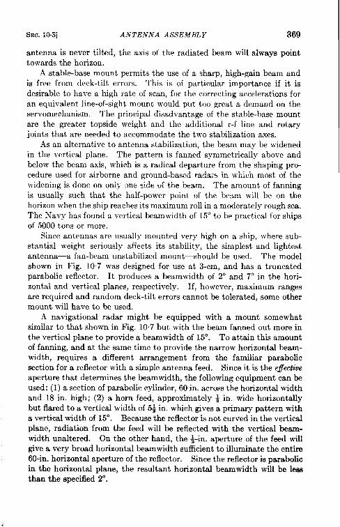
SEC. i&Sj ANTENNA ASSEMBLY 369
antenna is never tilted, the axis of the radiated beam will always pointtowards the horizon.
Astable-base mount permits the use of a sharp, high-gain beam andis free from deck-tilt errors. This is of particular importance if it isdesirable tohavea high rate of scan, forthecorrecting accelerations foran equivalent line-of-sight mount would put too great a demand on theservomechanism. The principal disadvantage of the stable-base mountare the greater topside weight and the additional r-f line and rotaryjoints that are needed to accommodate the two stabilization axes.
As an alternative to antenna stabilization, the beam may be widenedin the vertical plane. The pattern is fanned symmetrically above andbelow the beam axis, which is a radical departure from the shaping pro-cedure used for airborne and ground-based radars in which most of thewidening is done on onb~-one side of the beam. The amount of fanningis usually such that the half-power point of the beam will be on thehorizon when the ship reaches its maximum roll in a moderately rough sea.The Navy has found a vertical beamwidth of 15° to be practical for shipsof 5000 tons or more.
Since antennas are usually mounted very high on a ship, where sub-stantial weight seriously affects its stability, the simplest and lightestantenna—a fan-beam unstabilized mount—should be used. The modelshown in Fig. 10.7 was designed for use at 3-cm, and has a truncatedparabolic reflector. It produces a beamwidth of 2° and 7° in the hori-zontal and vertical planes, respectively. If, however, maximum rangesare required and random deck-tilt errors cannot be tolerated, some othermount will have to be used.
A navigational radar might be equipped with a mount somewhatsimilar to that shown in Fig. 10.7 but with the beam fanned out more inthe vertical plane to provide a beamwidth of 15°. To attain this amountof fanning, and at the same time to provide the narrow horizontal beam-width, requires a different arrangement from the familiar parabolicsection for a reflector with a simple antenna feed. Since it is the effectiveaperture that determines the beamwidth, the following equipment can beused: (1) a section of parabolic cylinder, 60 in. across the horizontal widthand 18 in. high; (2) a horn feed, approximately ~ in. wide horizontallybut flared to a vertical width of ~ in. which gives a primary pattern witha vertical width of 15°. Because the reflector is not curved in the verticalplane, radiation from the feed will be reflected with the vertical beam-width unaltered. On the other hand, the ~in. aperture of the feed willgive a very broad horizontal beamwidth sufficient to illuminate the entire60-in. horizontal aperture of the reflector. Since the reflector is parabolicin the horizontal plane, the resultant horizontal beamwidth will be lessthan the specified 2°.
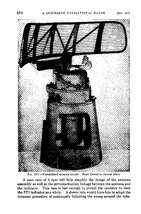
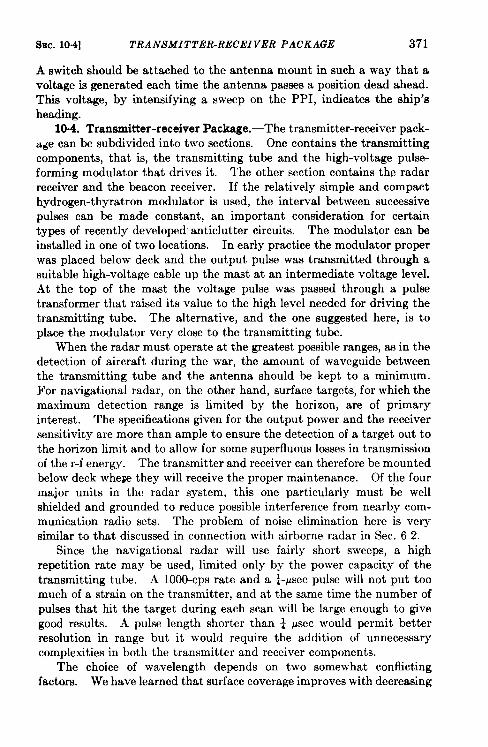
SEC. 10.4] TRANSMITTER-RECEIVER PACKAGE 371
A switch should be attached to the antenna mount in such a way that avoltage is generated each time the antenna passes a position dead ahead.This voltage, by intensifying a sweep on the PPI, indicates the ship’sheading.
10.4. Transmitter-receiver Package.-The transmitter-receiver pack-a~e can be subdivided into two sections. One contains the transmittingcomponents, that is, the transmitting tube and the high-voltage pulse-forming modulator that drives it. The other section contains the radarreceiver and the beacon receiver. If the relatively simple and compacthydrogen-thyratron modulator is used, the interval between successivepulses can be made constant, an important consideration for certaintypes of recently developed anticlutter circuits. The modulator can beinstalled in one of two locations. In early practice the modulator properwas placed below deck and the output pulse was transmitted through asuitable high-voltage cable up the mast at an intermediate voltage level.At the top of the mast the voltage pulse was passed through a pulsetransformer that raised its value to the high level needed for driving thetransmitting tube. The alternative, and the one suggested here, is toplace the modulator very close to the transmitting tube.
When the radar must operate at the greatest possible ranges, as in thedetection of aircraft during the war, the amount of waveguide betweenthe transmitting tube and the antenna should be kept to a minimum.For navigational radar, on the other hand, surface targets, for which themaximum detection range is limited by the horizon, are of primaryinterest. The specifications given for the output power and the receiversensitivity are more than ample to ensure the detection of a target out tothe horizon limit and to allow for some superfluous losses in transmissionof the r-f energy. The transmitter and receiver can therefore be mountedbelow deck whew they will receive the proper maintenance. Of the fourmajor units in the radar system, this one particular] y must be wellshielded and grounded to reduce possible interference from nearby com-munication radio sets. The problem of noise elimination here is verysimilar to that discussed in connection with airborne radar in Sec. 62.
Since the navigational radar will use fairly short sweeps, a highrepetition rate may be used, limited only by the power capacity of thetransmitting tube. A 1000-cps rate and a +psec pulse will not put toomuch of a strain on the transmitter, and at the same time the number ofpulses that hit the target during each scan will be large enough to givegood results. A pulse length shorter than ~ ysec would permit betterresolution in range but it would require the addition of unnecessarycomplexities in both the transmitter and receiver components.
The choice of wavelength depends on two somewhat conflictingfactors. We have learned that surface coverage improves with decreasing
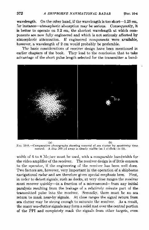
372 A SHIPBORNE NAVIGATIONAL RADAR [SEC.10.4
wavelength. On the other hand, if the wavelength is too short-1.25 cm,~or instance-atmospheric absorption may be serious. Consequently, itis better to operate on 3.2 cm, the shortest wavelength at which com-ponents are now fully engineered and which is not seriously affected byatmospheric attenuation. If engineered components were available,however, a wavelength of 2 cm would probably be preferable.
The basic considerations of receiver design have been mentioned inearlier chapters of the book. They lead to the conclusion that to takeadvantage of the short pulse length selected for the transmitter a band-
(a) (b)F1~, 10. S.—Comparative photographs showing removal of sea clutter by sensitivity time
control. A ship 500 yd away is c]early visible (at 1 o’c~ock) in (b).
width of 6 to 8 Me/see must be used, with a comparable bandwidth forthe video amplifier of the receiver. The receiver design is of little concernto the operator, if the engineering of the receiver has been well done.Two factors are, however, very important in the operation of a shipbornenavigational radar and are therefore given special emphasis here. First,in order to detect signals, such as docks, at very close ranges the receivermust recover quickly—in a fraction of a microsecond—from any initialparalysis resulting from the leakage of a relatively minute part of thetransmitted pulse into the receiver. Secondly, there must be no seareturn to mask near-by signals. At close ranges the signal return fromsea clutter may be strong enough to saturate the receiver. As a result,the many sea-clutter signals may form a solid mat over the central portionof the PPI and completely mask the signals from other targets, even
SEC. 10.5] INDICATOR 373
fairly large ones. The design characteristics which determine the resolu-tion for ordinary targets (short pulse length, narrow beamwidth, andfaat indicator sweeps) help eliminate sea clutter, but a sensitivity time-control (STC, see Sec. 1.2) circuit is more effective than any of these.
Two PPI photographs are presented in Fig. 10.8. The first showssea-clutter signals that appear with a “normal receiver,” that is, areceiver with constant gain. The two V-shaped indentations in thesignals were caused by shadows from a near-by mast and funnel. Thesignal from a ship only 500 yd away, indicated by an arrow, is completelymasked by sea clutter. The second photograph, taken less than a minutelater, shows the great reduction in sea clutter when an STC circuit is used.
These photographs cover a circle only a little more than 2 miles in
diameter. The sea conditions at the time the photographs were taken
were such that no appreciable sea-clutter signals were visible beyond a
range of about l+ miles. The STC circuit was adjusted so that beyond
that range there was no difference in the appearance of the PPI with or
without STC in operation.
1006. Indicator.—The superior accuracy of the M-M PPI for map-
matching techniques was cited in the previous chapter. Such PPI’swere built and put into service very early in the development of micro-
wave radars, and have been installed in the great majority of all shipborne
radars. The M-E PPI, which has the very marked advantage of contain-
ing no mechanically moving parts that require precision gears and bear-
ings, was not acceptable at that early date. The M-M PPI system lends
itself very readily to north stabilization, to the use of remote indicators,
and to other applications that make use of the existing systems of synchro-
transmitted positional data.
Radar indicators usually follow one of the two basic mechanical
designs shown in Figs. 10.9 and 10.10. The operating plan for the radar
determines which should be used. In the Navy, at least one operator
was assigned full-time to each radar. He was provided, almost without
exception, with a console or table-type indicator. Navy remote indi-
cators were usually deck-mounted and placed at various stations on the
ship for the convenience of men and officers with related duties who could
not spend full time at any one station. They could obtain information
from any of these indicators with a minimum of effort and confusion.
Probably only the largest commercial ships will have full-time radar
operators. The indicator will probably be mounted on the bridge where
it will be readily accessible to those concerned with navigation and
pilotage. For this purpose a deck-mount indicator with a horizontal
tube face is preferable.
The size of the indicator tube depends primarily on the type of cabinet
selected and on the way in which the indicator will be used. Three
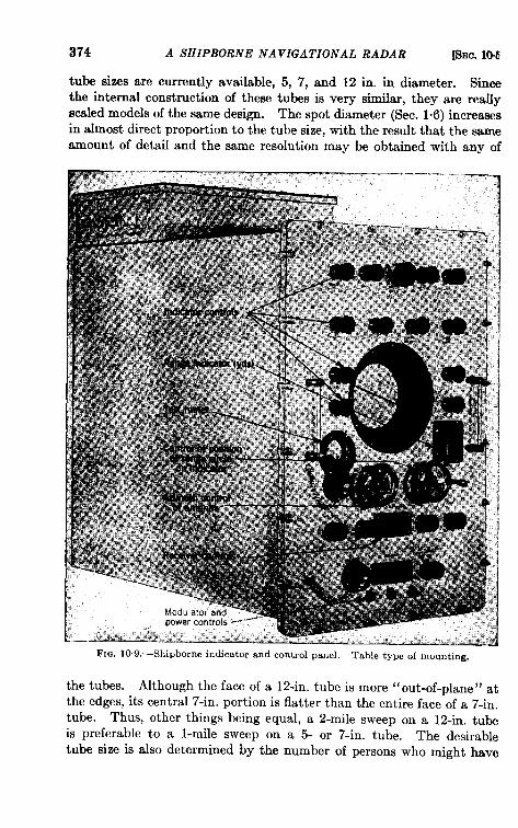
374 A SHIPBORNE NAVIGATIONAL RADAR [SEC.10.6
tube sizes are currently available, 5, 7, and 12 in. in diameter. Sincethe internal construction of these tubes is very simifar, they are reallyscaled models of the same design. The spot diameter (Sec. 1.6) increasesin almost direct proportion to the tube size, with the result that the sameamount of detail and the same resolution may be obtained with any of
—FIG. 10,9. —Shlpborne indicator and control panel. Table type of mounting.
the tubes. Although the face of a 12-in. tube is more “ out-of-plane” atthe edges, its central 7-in. portion is flatter than the entire face of a 7-in.tube. Thus, other things being equal, a 2-mile sweep on a 12-in. tubeis preferable to a l-mile sweep on a 5- or 7-in. tube. The desirabletube size is also determined by the number of persons who might have
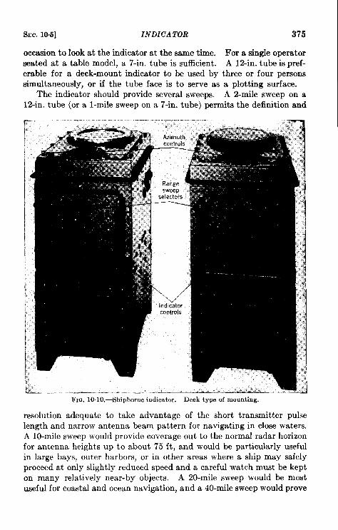
Src. 10.5] INDICATOR 375
occasion to look at the indicator at the same time. For a single operatorseated at a table model, a 7-in. tube is sufficient. A 12-in. tube ispref-erable for a deck-mount indicator to be used by three or four personssimultaneously, or if the tube face is to serve as a plotting surface.
The indicator should provide several sweeps. A Z-mile sweep on a12-in. tube (or a l-mile sweep on a 7-in. tube) permits the definition and
resolution adequate to take advantage of the short transmitter pulselength and narrow antenna beam pattern for navigating in close waters.A 10-mile sweep would provide coverage out to the normal radar horizonfor antenna heights up to about 75 ft, and would be particularly usefulin large bays, outer harbors, or in other areas where a ship may safelyproceed at only slightly reduced speed and a careful watch must be kepton many relatively near-by objects. A 20-mile sweep would be mostuseful for coastal and ocean navigation, and a 40-mile sweep would prove
376 A SHIPBORNE NAVIGATIONAL RADAR [SEC. 10.5
useful for making a landfall either of a high land mass or a high beaconinstallation.
The shipborne radar should have a movable range mark on the PPIwith the attendant circuits, mechanical gears, and a counter or dialmechanism to indicate the position of the movable marker in yards.Four or five fixed range marks on each sweep allow accurate estimates tobe made to a fifth or even a tenth of the distance between range marks.Thus, on the 2-mile sweep the four fixed range marks would subdividethe indicator into 1000-yd units and a target signal could be located bya visual estimate within one of these divisions with an accuracy of betterthan 200 yd. At the other extreme, the 40-mile sweep would be sub-divided into lo-mile divisions and a visual estimate would be no betterthan 1 mile. The fixed range marks should have an accuracy of 1 percent or better. The essential parts of the range-mark oscillator shouldbe well designed and packaged in a plug-in unit that can be replacedeasily should it become defective.
Since almost all large ships will be equipped with some type of gyro-compass in addition to a magnetic compass, directional data will beavailable for north-stabilizing the PPI. This great convenience isdefinitely worth the additional cost of the converter that may be neededto change the electrical output of the compass to a form readily assimi-lated by the radar. A switch on the indicator will provide means ofconverting the PPI to relative-bearing operation should the compass datafail or not be available.
It was mentioned previously in Sec. 7.13 that a radar is an excellentdevice for measuring ranges but is inferior to most optical methods fordetermining angular positions because of the relatively large bearnwidthsrequired. Some of the radar azimuthal errors, however, are of an instru-mental nature and arise either in the linkage between the antenna andindicator or in the indicator itself. It has already been seen that a goodservomechanism system may link the antenna and indicator with errorssubstantially less than 1°.
Nearly all shipborne radars measure bearings by the use of a graduatedring around the edge of the PPI tube. A mechanical cursor of some sortis added frequently to eliminate parallax errors introduced by the appre-ciable distance between the graduated ring and the sensitive surface ofthe indicator tube. The center of the graduated ring and the center ofthe cursor must coincide with the center of rotation of the electro-optical elements of the PPI tube or errors in bearing will result. Elec-tronic angle markers go through the same shifts as the target signals andare, therefore, not susceptible to such errors. Such markers are, ofcourse, absolutely essential for off-center PPI’s but do not seem necessaryfor the radar discussed here. Off-center PPI’s may be useful for mag-
SEC. 10.6] POWER SUPPLY 377
nifying a distant cluster of signals, but are not so free from distortion ascentered PPI’s.
Operating Controls.—Because the indicator may be the operatingcenter for the entire radar, most of the controls should be installed inthe indicator panel, along with a small meter and a selector switch bymeans of which the operator may quickly monitor most of the importantvoltages required for the operation of the several components. Thecontrols mounted on the indicator panel should be kept to a minimum,however, to avoid confusion and “over-manipulation” of the radar. Fora simple navigational radar the following controls seem desirable:
1. On-off switch for main power.2. On-off antenna rotation switch.3. Receiver (i-f) gain control.4. PPI range selector switch.5. Presentation selection switch: radar signals only, beacon signals
only, or both simultaneously.6. Beacon receiver (i-f) gain control.7. On-off switch for the high-voltage transmitter.
A secondary group of controls requiring only occasional adjustmentshould be placed beneath a hinged cover, but still in a position accessibleto a person observing the indicator.
1. Monitoring meter selector switch.2. Manual receiver-tuning and AFC on-off switches.
3. Manual beacon-receiver tuning and AFC on-off switches.
4. On-off switch for head marker of ship.
5. PPI focus.
6. PPI dial light control.
7. Relative-true bearing selector-switch.
A few other controls may be necessary to take care of production
tolerances in replaceable parts. Because these controls would be
adjust ed only when a part is replaced or when it is necessary to com-pensate, after a long period of operation, for aging and change in opera-
tional characteristics, they should be located inside the component as
near as possible to the associated parts.
1006. Power Supply .—The primary power supply on the ship may be
either direct or alternating current. The voltage at which direct current
is used is not great enough to meet the requirements of the electronic
circuits. If direct current is used, therefore, a special converter must be
supplied. If a-c power is used, however, the radar may be able to use
it directly. In general, however, the ship will have the wrong voltage or
378 A SHIPBORNE NAVIGATIONAL RADAR [%c. 10.6
a polyphase supply. Transformers or converters are necessary, therefore,for shipborne radars.
The converter output for the radar, furthermore, is usually unstablein both voltage and frequency because the primary power supplies aretraditionally unstable. If the radar is designed to operate on a supplywith a nominal rating, for example, of 115 volts and 60 cps, the compo-nents must be designed to operate satisfactorily with variations involtage bet ween 105 and 125 volts and variations in frequency between55 and 65 cps. The navigational radar discussed in this chapter shouldbe made to operate on single-phase, 115-volt, 60-cycle power; probablyless than 1 kw of power would be required.
The power-supply component of the radar is actually a collection oftransformers, rectifiers (perhaps both dry-disk and electronic-tube types),voltage regulators, and filters, which together supply the special voltagesrequired by the various other radar components.
It is usually impossible to use the same rectifier units on severalindependent circuits. For example, the modulator requires a high volt-age to drive the transmitting tube; the indicator tubes also requirerelatively high voltages, but they must be free of transient voltagescaused by the modulator. Similarly, the receivers require voltages thatare free of any disturbances from the indicator sweep circuits. Thesupplies to the various components may all be fused in the power-supplypackage, which then also serves as a junction and distribution box. Thefuses should be provided with blow-out indicators and the cables shouldterminate on simple strips. Since the installation is permanent in thesame sense as any other wiring on the ship, it is desirable that the wiresbe soldered in position. If this is not feasible, they should be securelyfastened with an individual screw or clamp for each wire. None of themany types of available cable connectors is entirely satisf act ory. Theyshould not be used except for very special applications—for example, inan installation that includes pulse transformers between the modulatorand the transmitting tube, it is necessary to terminate the interconnectinghigh-voltage cable with a special type of coaxial connector.
In tropical areas equipment is subject to the attack of fungi and othertropical microorganisms. Except for quantitative differences, the radarcomponents that are mounted at protected interior stations are sus-ceptible to deterioration to the same degree as other electronic equipmentsuch as communication radio transmitters and receivers. Frequently,however, one or more of the radar components are mounted in the open;these call for special design. The antenna, mounted at a high, relativelyinaccessible position, is a complex mechanical device that often includesseveral electrical components, each of which must be completely sealed.
In the past, small electronic equipment was usually shock-mounted in
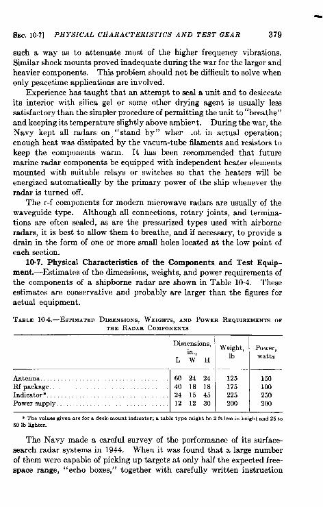
SEC. 107] PHYSICAL CHARACTERISTICS AND TEST GEAR 379
such a way as to attenuate most of the higher frequency vibrations.Siilar shock mounts proved inadequate during the war for the larger andheavier components. This problem should not be difficult to solve whenonly peacetime applications are involved.
Experience has taught that an attempt to seal a unit and to desiccateits interior with silica gel or some other drying agent is usually lesssatisfactory th& the simpler procedure of permitting the unit to “breathe”and keeping its temperature slightly above ambie~t. During the war, theNavy kept all radars on, ” stand by” wher .ot in actual operation;enough heat was dissipated by the vacum-tube filaments and resistors tokeep the components warm. It has been recommended that futuremarine radar components be equipped with independent heater elementsmounted with suitable relays or switches so that the heaters will beenergized automatically by the primary power of the ship whenever theradar is turned off.
The r-f components for modern microwave radars are usually of thewaveguide type. Although all connections, rotary joints, and termina-tions are often sealed, as are the pressurized types used with airborneradars, it is best to allow them to breathe, and if necessary, to provide adrain in the form of one or more small holes located at the low point ofeach section.
10.7. Physical Characteristics of the Components and Test Equip-ment.—Estimates of the dimensions, weights, and power requirements ofthe components of a shipborne radar are shown in Table 10.4. Theseestimates are conservative and probably are larger than the figures foractual equipment.
TABLE 1O,4.—ESTIMATED DIMENSIONS, WEIGHTS, AND POWER REQUIREMENTS OF
THE RADAR COMPONENTS
Dimensions,Weight, Power,
in.,LWH lb
watts
Antenna . . . . . . . . . 00 24 24 125 150Re package . . . . . 40 18 18 175 100Indicator . . . . . . . . . . . . . . . . . . 24 15 45 225 250Power supply... 12 12 30 200 200
* Thevnlueagivenarefor8 deck-mountindicator;8 tabletypemighthe2 ft lessh heightmd 25to50 lb lighter.
The Navy made a careful survey of the performance of its surface-search radar systems in 1944. When it was found that a large numberof them were capable of picking up targets at only half the expected free-space range, “echo boxes,” together with carefully written instruction
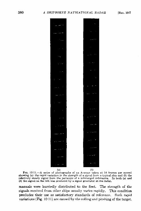
380 A SHIPBORNE NAVIGATIONAL RADAR [SEC. 10.7
(a) (b)FIG. 101 1.—A series of photographs of an A-scope taken at 16 frames per second
showing (a) the rapid variation in the strength of a signal from a typical ship and (b) therelatively steady signal from the periscope of a submerged submarine. In both (a) snd(b) the signal on the left was produced by a signal generator at the radar.
manuals were hurriedly distributed to the fleet. The strength of thesignals received from other ships usually varies rapidly. This conditionprecludes their use as satisfactory standards of reference. Such rapidvariations (Fig. 10”11) are caused by the rolling and pitching of the target.
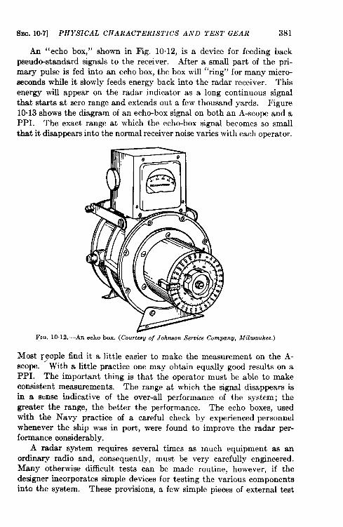
SEC. 10.7] PHYSICAL CHARACTERISTICS AND TEST GEAR 381
An “echo box,” shown in Fig. 10.12, is a device for feeding backpseud~standard signals to the receiver. After a small part of the pri-mary pulse is fed into an echo box, the box will “ring” for many micro-seconds while it slowly feeds energy back into the radar receiver. Thisenergy will appear on the radar indicator as a long continuous signalthat starts at zero range and extends out a few thousand yards. Figure10.13 shows the diagram of an echo-box signal on both an A-scope and aPPI. The exact range at which the echo-box signal becomes so smallthat it disappears into the normal receiver noise varies with each operator.
FIG. 10. 12.—An echo box. (Courtesu of Johnson Service Company, Milwaukee.)
Most ~~ople find it a little easier to make the measurement on the A-scope. With a little practice one may obtain equally good results on aPPI. The important thing is that the operator must be able to makeconsistent measurements. The range at which the signal disappears isin a sense indicative of the over-all performance of the system; thegreater the range, the better the performance. The echo boxes, usedwith the Navy practice of a careful check by experienced personnelwhenever the ship was in port, were found to improve the radar per-formance considerably.
A radar system requires several times as much equipment as anordinary radio and, consequent y, must be very carefully engineered.Many otherwise difficult tests can be made routine, however, if thedeeigner incorporates simple devices for testing the various componentsinto the system. These provisions, a few simple pieces of external test
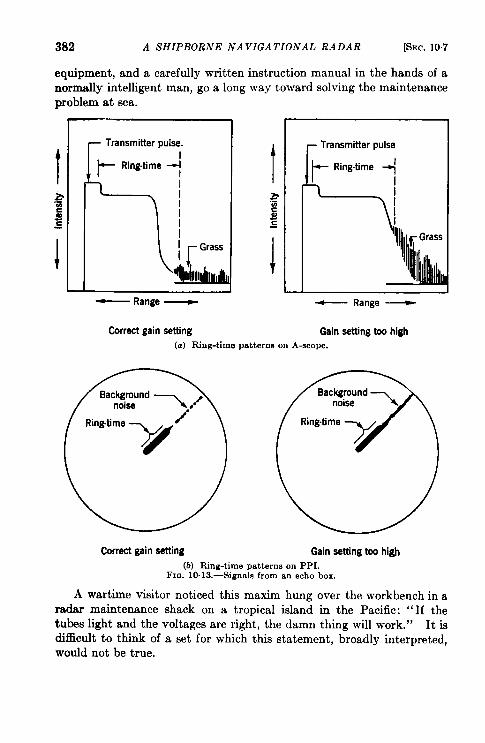
382 A SHIPBORNE NAVIGATIONAL RADAR [SEC. 10.7
equipment, and a carefully written instruction manual in the hands of anormally intelligent man, go a long way toward solving the maintenanceproblem at sea.
~ Transmitter pulse.
L
_ Range _
Correct gain setting
Transmitter pulse
I t
bilk
Ring-time 1’
,*a;= 1
1
l!f Grass
I
1 1
_ Range _
Gain setting too high
(a) Ring-time patterns on A-scope.
C%rrect gain setting Gain setting too high
(b) Rhlg-time patterns on PPI.FIa. 10. 13.—Signals from an echo box.
A wartime visitor noticed this maxim hung over the workbench in aradar maintenance shack on a tropical island in the Pacific: “If thetubes light and the voltages are right, the damn thing will work.” It isdifficult to think of a set for which this statement, broadly interpreted,would not be true.
Index
A
ADF, 46advantages of, 53limitations of, 53use of, 53
Aero Service Corporation, 32AFC, 143Airplane detection over water, 115Altimeter, frequency-modulated, 13*
141pulsed, and f-m, comparison of, 141radio, 131–142
pulsed, 132-136Altitude determination, 131–142American Machine and Foundry Com-
pany, 222Amplidynes, 28Amplifier, intermediate-frequency, 10
video, 10AN/APN-1, 13G141AN/APQ-7, 187AN/APQ-13, 187AN/APS-3, 186AN/APS-10, 171-185
beacon response of, 175components of, 180coverage diagram of, 176future trends of, 185performance of, 173technical characteristics of, 182
AN/APs-15, 186AN/MPN-l (see GCA)Antenna, 5
microwave radar, 194Antenna assembly of shipborne naviga-
tional radar, 364Antenna gain (see Gain, antenna)Antenna size, beamwidth, and wave-
length, relation between, 14Antenna stabilization (see Stabilization,
antenna)Antennas, 155
airborne, 155
Antennas, search and height-finding, onsingle mount, 221
shipborne, 367–370Anticlutter circuits, advantages of, illus-
tration of, 197effects of, 114
Anticollision devices, for use over land,129
for use over water, 129Anticollision radar devices, 12%131
AN/TPS-10, 219-227AN/TPS-10 mount, 215AN/TPS-10 presentation, 217AN/TPS-10 range-height indicator, 216Approach, final, control in, 30&310
instrument, standard, 291Approach system, beam, 227–232
beacon (see BABS)GCA (see GCA)
ARP (see Radar projector, autofocus)ASB-3, 186A-scope, 30A-scope presentation, 31Aslakson, Lt. Col. Carl, 282Attenuation, atmospheric, 22
by nitrogen, 22by oxygen, 22by precipitation, 22by water vapor, 25
Automatic frequency control (see AFC)Ayres, R. C., 187Azimuth accuracy, 12Azimuth error, radar, 367Azimuth markers, 148Azimuth resolution, 12
and beamwidth of antenna, 14Azimuth stabilization, aircraft, 149
ships, 367–371
B
BABS, 232-237BABS airborne reception and indication,
234
383
384 RADAR AIDS TO NAVIGATION
BABS ground responder beacons, 233BABS interrogation, 233BABS L-scope localizer presentation, 234BABS system, American 200-Mc, L-
scope presentation of, 235British, recent, ‘indicator for, 235
Baltzer, O. J., 358Bats, 3Beacon, airborne, 25&258
maximum and minimum range with,257
application of, 37coding of, (see Coding)
future developments of, 40ground, cost of, 189ground based, special applications of,
121
interrogation of, 36marine design, 323marine radar, 322–324
location of, 322operational use of, 322
omnidirectional, 51radar, 3&43
block diagram of, 38separate-band, 42special provisions for, in radar, 40
Beacon equipment, 39Beacon navigation, radar, 117-121Beacon systems, 42
radar, 257
Beacon transmitter, 36Beacon transmitter frequency, 40
Beam, anterma, 5Beamwidth, antenna, 12
and azimuth resolution, 14anterma size, and wavelength, relation
between, 14resolution with different, photographs
showing, 365
Bearing, measurement of, 9
Bearing transmission circuit for shipnavigation radar, 34
Beavertail, 210
Beavertail systems, 215-223
Bendix Aviation Corporation, 247
Blind-landing system, bolometer, 228
Boundaries, land-water, 90
British Air Ministry, 73B-scone, 35
c
Cathode-ray tubes, 26Chart matching, 335 (See also Naviga-
tion, ship, superposition)accuracy obtainable by, 344indicator requirements for, 35o
Chart-matching devices, suggestedprovements for, 351
Chart-matching equipment, 335Cities, general features of. 91-96
im-
Civil A&onautics Admini&ration, 287Coding of beacons, 40
frequency, 41pulse-width, 41range, 36space, 41
Cold front, radar echoes from, 320Compass, airborne radio, advantages of,
53disadvantages of, 53
radio, 46Corner reflectors, 324
clusters of, 326, 328dropped from airplane, 1124-ft, 330mounted on life raft, 329square, 325triangular, 325
Cosecant-squared coverage (see Cover-age, cosecant-squared)
Counter, V. A., 358Course indication, 117Course indicator method of navigation,
119Coverage, 14
cosecant-squared, 15Coverage diagram, of GCA antennas, 242
of long-range microwave radar system,202
Cowan, E. W., 113Cross-sectional area, effective, 16Cruft Laboratory, 49Curvature of earth, 21
D
Decca, 76Dipole, 16Direction finders, airborne, 51–54
automatic (see ADF)
INDEX
Direction finders, ground, 54uhipbome, 51–54
Distortion, associated with resolvingpower, 91
due to finite beamwidth and pulselength, 153
range, on PPI, 151Doppler frequency shift, 107Doppler method, possibility of ground-
speed determination by, 110Drift, measurement of, 105-110
over water, determination of, 110Drift determination, doppler, 107Durkee, A. L., 263
E
Echo box, 381Errors, deck-tilt, 364
F
Fairbank, W. M., 358Filter room, 200Fixes, taking with beacons, 117Flight rules, contact, CFR, 288
instrument, IFR, 288Flights, over water, information avail-
able on, 112-115Fyler, G. W., 31, 320
G
Gain, antenna, 16Galambos, R., 3Gating system, block diagram of, 205GCA, 227, 237-251
advantages and limitations of, 248-251
antenna beam coverages of, 242near Verdun, France, 238PPI of, 241
GCA azimuth and elevation assemblies,244
GCA operations, trailer, interior of, 240GCA presentation, 241, 245-247, 249Gee, 60-64
homing with, 63limitations of, 63
Gee coverage, in United Kingdom, 61Gee system indication, 62General Electric Company, 29, 31, 32oGilbert, G. A., 287Glide-path system, 227
385
Gordy, W. O., 358
Goudsmit, S. A., 69GPI, 122-128Griffin, D. R., 3Ground-based scanning radar systems,
237-251Ground control of approach (see GCA)Ground-position indicator (see GPI)Ground speed, measurement of, 105-110
over water, determination of, 110Ground-speed determination, instantane-
ous, possibility of, by dopplermethod, 110
H
Haneell, C. W,, 260, 262Height finders, 207-227
beavertail, 10-cm, mount of, 218Height finding, accuracy of, absolute and
relative, 212effect of elevation beamwidth on,
213methods of, 207
long-wave, 208pencil beam with conical scan, 210V-beam, 211vertically scanned beams, 210
Hexem, J., 274Hight, S. C., 263Hollingsworth, L. M., 261, 265Homing with Gee, 63Horn antenna feed, 15, 16Hudspeth, E. L., 328, 358Hyperbolic navigation, principle of, 57Hyperbolic systems, accuracy of, 77
automatic piloting by, 82-85of navigation, 56-60positional accuracy of, 59range of, 77
I
IFF system, 42Indicator, 7, 26-36
design considerations for, 148-155plan position (see PPI)presenting search and height data, 223for shipborne navigational radar, 373-
377types of, 3&36
(See also specific types of indicators)
386 RADAR AIDS TO NAVIGATION
Interrogator-responsor,42Ionosphere,reflectionsfrom, 71
J
James,H. M., 264, 366
LLandfall, 112Landing, final,control in, 306-310
radaraids for, 227-251Landingaids (seeApproachsystem)Landing system, bolometer, 228Laweon,A. W., Jr., 261, 265LF Loran (seeLoran,LF)Life of singlepulse, 8Lobe region,356Lobes, eide, 13Localizersyetem,227Logemann,H., Jr., 261Loran, 64-70
automaticdata analysieof, 79-82averageerrorsof 6Xfor, 66dieadvantageeof, 70LF, 72-76
averageposition-lineerror,74indication,75
Ss, 70-73
chart, 73
quadrilateral, 72
Lorrm coverage, New York to Bermuda,69
Loran indicator, 67
Loran plotting-board chart with branprojection, 81
Loran etation on Fame Islande, 6SLoran system indication, 65I.orhurnb line, 84, 85Low-frequency Loran (se. Loran, LF)L-scope localizer presentation, 234L-scope presentation of American 200-Mc
BABS eystem, 235
Mc
McLaughlin, D. B., 353
M
*cc, 4Map, radar, 346-359
of Boeton, Mass., 97, 99of Chicago, Ill., 100of Detroit, Mich., 100of New York, N. Y., 98of northeasternU. 8. A., 90
Mapping, radar, details in, 96built-up areas, 9W101mountain relief, 103returne from highways
ways, 101, 102and run-
features revealed by, 89-96radar aids to, 27S2S4
Maps, use of, as aids to radar pilotage, 115Markers (see Azimuth, Height, Range
markers)Martin, E. G., 331Matching techniques, 333Measurements, short-range, 279Microsecond, Met, 4
Microwaves, definition of, 21Miller, E. E., 353Modulator, 5Morgan, H. K., 187Moving target indication (see MTI)MTI, 252-256
airborne, 255block diagram of radar set with, 252delay line for use with, 253performance of, 253ehipborne, 255
MTI response curves for lo-cm operation,255
Myers, W. L., 166
N
Nash, J. P., 328National Advisory Committee for Avia-
tion, 158Navigation,air, and traffic control, 285-313
available radar aids for, 293hmitatione of present system, 291special equipment for, 302statement of problem of, 285–287summary of proposed radar aids
for, 311–313using airborne radar aids, 293–299using ground-based radar aids,
29%310(See ako Traffic control)
celestial, 55hyperbolic systems of (see Hyperbolic
systems of navigation)radar beacon, 117–121chip, and pilotage, 3 17–353
how radar can help in, 317-320
INDEX 387
Navigation, ship, superposition, 331bibliography of literature on, 353principle of, 331–335
(See also Chart matching)Navigation methods, nonradar, 44-85Navigation radar, ship, bearing trans-
mission circuit for, 34Navigational aids, ultrahigh-frequency,
50Navigational microfilm projector, 338Navigational nets, 5&85NMP (see Navigational microfilm pro-
jector)Noise, 16Noise power, background, of receiving
system, 19
0
Operating controls of shipborne naviga-tional radar, 377
Operator, radar, 105Oscilloscope, 26
P
Paraboloids, 14Paracourse lines, 119Pass band, 10PGP, 228-232
cross-pointer meter for, 230evaluation of, 231
Piloting, automatic, by hyperbolic sys-tems, 82–85
Plan position indicator (see PPI)Plotting board, example of, 201Polarization and sea return, 113Position, identification of, by group of
signals, 93by shape of built-up areas, 94
Power, pulse, of transmitter, 15Power supply of shipborne navigational
radar, 377–379PPI, 5, 3G35
on D-day, 203of GCA, 241of high-resolution shipborne radar, 318Magnetic-Electric (ME), 34Magnetic-Mechanical (MM), 34Magnetic-Selsyn (MS), 34off-center, 199
PPI, range distortion on, 151resolved current type, 34resolved voltage type, 34rotating coil, 34typhoon on, 321
PPI circuit, 33PP1 pattern superimposed on map, 337PPI photograph taken from ship in
Boston Harbor, 319, 365PP1 presentation of northeastern L~nitcd
States, 90PPI reflectoscope, virtual, 336PP1 simulations, 351Precipitation, attenuation by, 22PRF, (see Repetition rates)Propagation, 21-26
anomalous, effects of, 220nonstandard, 360–363of radar waves, over water, 354–363
Pulse, single, life of, 8Pulse length, 19Pulse repetition frequency (see Repetition
rates)Pulsed glide path (see PGP)
R
Radar, airborne, characteristics of, 89–121
design considerations, 165-171economic aspects of, 187electrical noise interference and its
elimination, 169performance of AN/APS-10, 171-
185performance of some existing sys-
tems, 185primary electrical power for, 169radome problems, 161–165scanner installation, 161-165test equipment, 170
fundamental ideas of, 3-10ground-based, 193–227Handy, 280principles of, 3-43shipborne navigational, antenna as-
sembly of, 3M–371general specifications for, 363indicator for, 373–377physical characteristics of com-
ponents of, 379specifications for, 363–382
388 RADAR A[DJS TO NAVIGATION
Radar, shipborne navigational testequipment for, 379–383
transmitter-receiver package for,
371-373sonic analogy to, 4
Radar aids, to air navigation (see Navi-gation, air; Traffic control)
for landing, 227-251to mapping, 278-284to navigation of ships (see Navigation,
ship)to traffic control (see Navigation, air;
Traffic control)Radar antenna (see Antenna, radar)Radar beacons (see Beacons, radar)Radar chart projector, 341Radar design, for use with marine
beacons, 323Radar earth, 22
Radar map (see Map, radar)
Radar mapping (s.. Mapping, radar)
Radar pilotage, usc of maps as aids to,115
Radar-pilotage maps, 115
Radar projector, autofocus, 340
Radar pulses, 4
Radar relay, 258-267amplitude modulation, 264choice of frequency for, 261–263comparative photographs of, 266frequency modulation, 264general design problem of, 260intermediate stations for, 264minimum usable signal, 260muIticharmel transmission, 264summary of, 265synchronization of, 265
Radar relay link, type-A, 258type-B, 259
Radar systems, for airway and airportcontrol, proposed rough specifica-tions of, 301
automatic tracking, 202–207microwave, long-range, 193–X)2
coverage diagram of, 202range of, 196
Radiator, isotropic, 17
R.adiO altimeters (ace Altimeters, radio)Radio Corporation of America, 132,
136
Radio range, 44-47German, 47–5osingle, navigation by means of, 45
uhf, 50visual two-course, 50
Radio-range navigation, advantages of,
46aids to, 46limitations of, 46
Radome problems, 161-165Range, measurement of, 5
minimum, 10radio, (see Radio range)slant, 151
Range equation, 15–18Range-height indicator (s.. RHI)Range markers, 148Range resolution, 10, 14
importance of, 150Rapid scan system, 187RCP (see Radar chart projector)Receiver, 7
design consideration, 143–148Recognition of indicator patterns, 331Refraction, atmospheric, 21
standard, 22Relay radar (see Radar relay)Repetition rate, 16, 18Reproduction of canned data, 268Resolution, with different beamwidth,
photograph showing, 365range, importance of, 150
Resolving power, distortion associatedwith, 91
RHI, 36, 210RHI presentation, 217
of 10-cm height tinder, 219Robinson scanner, 222
s
Samson, E. W., 265Sandretto, P. C., 45, 50,Scan system, rapid, 187Scanner, Robinson, 222
52, 54
Scanner installation, 161-165
Scanning, types of for airborne systems,155
Scanning loss, 19, 214
scanning rate, 155, 214
INDEX 389
Scanning techniques, for automatic track-ing, 203
Scattering, 22SCR-718C, 132-136Sea clutter, removal of, by sensitivity
time control, 372Sea return, and its alleviation, 112–1 15
and polarization, 113Searchlighting, 19Sensitivity time control, 11, 13, 146
removal of sea clutter by, 372Servomechanism 9, 28Ship detection, by airborne radar, 112Shoran, 281-284
accuracy obtainable by, 284Shoran equipment, airborne station, 282Shoran ground station, 281-283Signal, minimum discernible, 16, 20Sinsheimer, R, L., 185Smith, C, A., 353Sonic analogy to radar, 4Sonne, 47–50Spencer, R, C,, 327Sperry Gyroscope Company, 230Squint angle, 204SS Loran (s.. Loran, SS)Stabilization, airborne antenna, 156–160
azimuth, 149methods of, 159roll, 160of shipborne navigational radar, 367–
371Stabilization requirements, airborne
radar, 158Storm detection, 104Sturtevant, J, M,, 261, 265Surface region, 357-360Surface vessel detection, 112Sweep, 7Synchronizer, 5Synchros, 28
T
Temporal gain control, 11Three-tone provisions, for PPI 144
Time-varied gain, 11, 146Traffic control, in approach zones, 304
by ground radar, advantages andlimitations of, 310
Traffic-control system, present, 287-293Transmitter, 5Transmitter-receiver package, 371-373Transponder, 36Trigger, 5Typhoon, on PPI, 321
u
United States Army, 133, 216, 217, 233,244
U,,ited States Army .4ir Force, 282, 283
v
V-beam, 211V-beam control room, 226V-beam mount, 224V-beam presentation, 225Video, 7Video mapping, 267-278
applications of, 270to GCAj 272
delineation of flight paths by, 271equipment for, 275general principles of, 267precision of, 273reproduction by different methods,
examples of, 27&277reproduction of “canned” data by, 268reproduction of live data by, 274
Virtual PPI reflectoscope (s.. PPIreflectoscope, virtual)
VPR (see PPI reflectoscope, virtual)
w
Wavelength, 14beamwidth, and antenna size, relation
between, 14choice of, 20, 195–198, 371