minivol portable air sampler operation manualfile.yizimg.com/362947/2012080217290548.pdf · minivol...
TRANSCRIPT
-
MiniVolPortable Air Sampler
Operation Manual
Airmetrics2095 Garden Ave.
Suite 102Eugene, OR 97403
U.S.A.
PHONE: 541. 683.5420FAX: 541. 683.1047
E-mail: [email protected] www.airmetrics.com
Notice:
Information in this manual is subject to change without notice and does not represent a commitmenton the part of Airmetrics, which reserves the right to make changes in construction, design,specifications, and/or procedures that may not be reflected in this manual.
Http://www.menglianggroup.com E-mail: [email protected] QQ: 2351462123

Printing History
Manual Version 1.0 - October, 1992, applies to Sampler Models 3.xManual Version 1.0a - November, 1992, applies to Sampler Models 3.xManual Version 1.1 - June, 1993, applies to Sampler Model 4.0Manual Version 1.1a - January, 1994, applies to Sampler Model 4.0Manual Version 1.2 - December, 1994, applies to Sampler Model 4.0Manual Version 1.2a - July, 1996, applies to Sampler Model 4.1Manual Version 4.2 - May, 1997 applies to Sampler Model 4.2Manual Version 4.2a - February, 1998 applies to Sampler Model 4.2Manual Version 4.2b - December, 2000 applies to Sampler Model 4.2Manual Version 4.2c - June, 2001 applies to Sampler Model 4.2Manual Version 5.0 - February, 2006 applies to sampler model 5.0Manual Version 5.0a - January, 2007 applies to sampler model 5.0Manual Version 5.0b - June, 2007 applies to sampler model 5.0 (High Efficiency Pump)
Http://www.menglianggroup.com E-mail: [email protected] QQ: 2351462123

Table of Contents
Airmetrics i
Table of Contents
1: INTRODUCTIONPrinciples of Operation . . . . . . . . . . . . . . . . . . . . . . . . . . . . . . . . . . . . . . . . . . . . . . . . . . . . . . . . . . 1
Particulate Matter Sampling Mode . . . . . . . . . . . . . . . . . . . . . . . . . . . . . . . . . . . . . . . . . . . . . 1Integrated Gas Sampling Mode . . . . . . . . . . . . . . . . . . . . . . . . . . . . . . . . . . . . . . . . . . . . . . . . 2
2: GETTING STARTED 3Inspecting Components . . . . . . . . . . . . . . . . . . . . . . . . . . . . . . . . . . . . . . . . . . . . . . . . . . . . . . . . . 3Charging Batteries . . . . . . . . . . . . . . . . . . . . . . . . . . . . . . . . . . . . . . . . . . . . . . . . . . . . . . . . . . . . . 3Removing Pump and Timer Assembly . . . . . . . . . . . . . . . . . . . . . . . . . . . . . . . . . . . . . . . . . . . . . 4Turning the Sampler On/Off . . . . . . . . . . . . . . . . . . . . . . . . . . . . . . . . . . . . . . . . . . . . . . . . . . . . . . 4Programming the Timer . . . . . . . . . . . . . . . . . . . . . . . . . . . . . . . . . . . . . . . . . . . . . . . . . . . . . . . . . 5
Setting the Real-Time Clock . . . . . . . . . . . . . . . . . . . . . . . . . . . . . . . . . . . . . . . . . . . . . . . . . . 5Setting the On/Off Times . . . . . . . . . . . . . . . . . . . . . . . . . . . . . . . . . . . . . . . . . . . . . . . . . . . . . 5Setting the Timer to “On,” “Auto,” and "Off" Modes . . . . . . . . . . . . . . . . . . . . . . . . . . . . . . . . . 6
Checking for Leaks . . . . . . . . . . . . . . . . . . . . . . . . . . . . . . . . . . . . . . . . . . . . . . . . . . . . . . . . . . . . 6
3: CONTROLS AND ADJUSTMENTSAll Operating Modes . . . . . . . . . . . . . . . . . . . . . . . . . . . . . . . . . . . . . . . . . . . . . . . . . . . . . . . . . . . 7
Elapsed Time Totalizer . . . . . . . . . . . . . . . . . . . . . . . . . . . . . . . . . . . . . . . . . . . . . . . . . . . . . . 7Programmable Timer . . . . . . . . . . . . . . . . . . . . . . . . . . . . . . . . . . . . . . . . . . . . . . . . . . . . . . . 7Flowmeter . . . . . . . . . . . . . . . . . . . . . . . . . . . . . . . . . . . . . . . . . . . . . . . . . . . . . . . . . . . . . . . . 8Flow Rate Adjustment . . . . . . . . . . . . . . . . . . . . . . . . . . . . . . . . . . . . . . . . . . . . . . . . . . . . . . . 8Low Battery Indicator . . . . . . . . . . . . . . . . . . . . . . . . . . . . . . . . . . . . . . . . . . . . . . . . . . . . . . . . 8Lo-Flow/Lo-Battery Reset Button . . . . . . . . . . . . . . . . . . . . . . . . . . . . . . . . . . . . . . . . . . . . . . 8ON/AUTO/OFF Button . . . . . . . . . . . . . . . . . . . . . . . . . . . . . . . . . . . . . . . . . . . . . . . . . . . . . . 8
Integrated Gas Sampling Option . . . . . . . . . . . . . . . . . . . . . . . . . . . . . . . . . . . . . . . . . . . . . . . . . . 9Solenoid Valve Output Connectors . . . . . . . . . . . . . . . . . . . . . . . . . . . . . . . . . . . . . . . . . . . . . 9Active Solenoid Output Indicators . . . . . . . . . . . . . . . . . . . . . . . . . . . . . . . . . . . . . . . . . . . . . . 9Manual Sequence Advance Button . . . . . . . . . . . . . . . . . . . . . . . . . . . . . . . . . . . . . . . . . . . . . 9Pulse Interval Adjustment . . . . . . . . . . . . . . . . . . . . . . . . . . . . . . . . . . . . . . . . . . . . . . . . . . . . 9Pulse Duration Adjustment . . . . . . . . . . . . . . . . . . . . . . . . . . . . . . . . . . . . . . . . . . . . . . . . . . 10Power On/Off . . . . . . . . . . . . . . . . . . . . . . . . . . . . . . . . . . . . . . . . . . . . . . . . . . . . . . . . . . . . . 10Pulse Indicator . . . . . . . . . . . . . . . . . . . . . . . . . . . . . . . . . . . . . . . . . . . . . . . . . . . . . . . . . . . . 10Overlap Jumper . . . . . . . . . . . . . . . . . . . . . . . . . . . . . . . . . . . . . . . . . . . . . . . . . . . . . . . . . . . 10
4: PARTICULATE MATTER SAMPLINGConsumables . . . . . . . . . . . . . . . . . . . . . . . . . . . . . . . . . . . . . . . . . . . . . . . . . . . . . . . . . . . . . . . . 11Siting Requirements . . . . . . . . . . . . . . . . . . . . . . . . . . . . . . . . . . . . . . . . . . . . . . . . . . . . . . . . . . . 11Attaching the Mounting Cradle . . . . . . . . . . . . . . . . . . . . . . . . . . . . . . . . . . . . . . . . . . . . . . . . . . . 11Preparing the Sampler . . . . . . . . . . . . . . . . . . . . . . . . . . . . . . . . . . . . . . . . . . . . . . . . . . . . . . . . . 11
Flow Rate . . . . . . . . . . . . . . . . . . . . . . . . . . . . . . . . . . . . . . . . . . . . . . . . . . . . . . . . . . . . . . . 13Flowmeter Calibration . . . . . . . . . . . . . . . . . . . . . . . . . . . . . . . . . . . . . . . . . . . . . . . . . . . . . . 13
Preseparator/Filter Holder Assembly . . . . . . . . . . . . . . . . . . . . . . . . . . . . . . . . . . . . . . . . . . . . . . 14Clean and Grease Impactor . . . . . . . . . . . . . . . . . . . . . . . . . . . . . . . . . . . . . . . . . . . . . . . . . 14Installing Filters . . . . . . . . . . . . . . . . . . . . . . . . . . . . . . . . . . . . . . . . . . . . . . . . . . . . . . . . . . . 14
Preparing the Battery Pack . . . . . . . . . . . . . . . . . . . . . . . . . . . . . . . . . . . . . . . . . . . . . . . . . . . . . 15Battery Charging . . . . . . . . . . . . . . . . . . . . . . . . . . . . . . . . . . . . . . . . . . . . . . . . . . . . . . . . . . 15Changing/Installing Battery Pack on Sampler . . . . . . . . . . . . . . . . . . . . . . . . . . . . . . . . . . . . 15Other Battery Checks . . . . . . . . . . . . . . . . . . . . . . . . . . . . . . . . . . . . . . . . . . . . . . . . . . . . . . 16
Setting the Desired Sampling Time . . . . . . . . . . . . . . . . . . . . . . . . . . . . . . . . . . . . . . . . . . . . . . . 16Particulate Matter Sampling Procedure . . . . . . . . . . . . . . . . . . . . . . . . . . . . . . . . . . . . . . . . . . . . 16
Http://www.menglianggroup.com E-mail: [email protected] QQ: 2351462123

Airmetrics MiniVol Users Guide
ii Airmetrics
Particulate Matter Sample Retrieval . . . . . . . . . . . . . . . . . . . . . . . . . . . . . . . . . . . . . . . . . . . 17Exposed Filter . . . . . . . . . . . . . . . . . . . . . . . . . . . . . . . . . . . . . . . . . . . . . . . . . . . . . . . . . . . . 18Error Conditions . . . . . . . . . . . . . . . . . . . . . . . . . . . . . . . . . . . . . . . . . . . . . . . . . . . . . . . . . . 18
Low Battery Indicator ON . . . . . . . . . . . . . . . . . . . . . . . . . . . . . . . . . . . . . . . . . . . . . . . . 18Low Flow Indicator ON . . . . . . . . . . . . . . . . . . . . . . . . . . . . . . . . . . . . . . . . . . . . . . . . . . 19Overriding Low Flow/Low Battery Indicators . . . . . . . . . . . . . . . . . . . . . . . . . . . . . . . . . . 19
5: INTEGRATED GAS SAMPLINGConsumables . . . . . . . . . . . . . . . . . . . . . . . . . . . . . . . . . . . . . . . . . . . . . . . . . . . . . . . . . . . . . . . . 21Siting Requirements . . . . . . . . . . . . . . . . . . . . . . . . . . . . . . . . . . . . . . . . . . . . . . . . . . . . . . . . . . . 21Attaching the Mounting Cradle . . . . . . . . . . . . . . . . . . . . . . . . . . . . . . . . . . . . . . . . . . . . . . . . . . . 21Preparing the Sampler . . . . . . . . . . . . . . . . . . . . . . . . . . . . . . . . . . . . . . . . . . . . . . . . . . . . . . . . . 21Adjusting Pulse Frequency and Duration . . . . . . . . . . . . . . . . . . . . . . . . . . . . . . . . . . . . . . . . . . . 24
Pulse Interval Adjustment . . . . . . . . . . . . . . . . . . . . . . . . . . . . . . . . . . . . . . . . . . . . . . . . . . . 24Pulse Duration Adjustment . . . . . . . . . . . . . . . . . . . . . . . . . . . . . . . . . . . . . . . . . . . . . . . . . . 24
Preparing the Sampler . . . . . . . . . . . . . . . . . . . . . . . . . . . . . . . . . . . . . . . . . . . . . . . . . . . . . . . . . 25Installing Tedlar® Bags and Attaching Canisters . . . . . . . . . . . . . . . . . . . . . . . . . . . . . . . . . . . . 26Integrated Gas Sampling Procedure . . . . . . . . . . . . . . . . . . . . . . . . . . . . . . . . . . . . . . . . . . . . . . 27Gas Sample Retrieval . . . . . . . . . . . . . . . . . . . . . . . . . . . . . . . . . . . . . . . . . . . . . . . . . . . . . . . . . 27
6: HARDWARE DESCRIPTION 29Pneumatic System . . . . . . . . . . . . . . . . . . . . . . . . . . . . . . . . . . . . . . . . . . . . . . . . . . . . . . . . . . . . 29
Pneumatic System Flow Schematic . . . . . . . . . . . . . . . . . . . . . . . . . . . . . . . . . . . . . . . . . . . 29Filter Holder Assembly . . . . . . . . . . . . . . . . . . . . . . . . . . . . . . . . . . . . . . . . . . . . . . . . . . . . . 29Flowmeter . . . . . . . . . . . . . . . . . . . . . . . . . . . . . . . . . . . . . . . . . . . . . . . . . . . . . . . . . . . . . . . 29Flow Control System . . . . . . . . . . . . . . . . . . . . . . . . . . . . . . . . . . . . . . . . . . . . . . . . . . . . . . . 29Miniature D.C. Double Diaphragm Pump . . . . . . . . . . . . . . . . . . . . . . . . . . . . . . . . . . . . . . . 29Electronics System . . . . . . . . . . . . . . . . . . . . . . . . . . . . . . . . . . . . . . . . . . . . . . . . . . . . . . . . 30Motherboard . . . . . . . . . . . . . . . . . . . . . . . . . . . . . . . . . . . . . . . . . . . . . . . . . . . . . . . . . . . . . 30Power . . . . . . . . . . . . . . . . . . . . . . . . . . . . . . . . . . . . . . . . . . . . . . . . . . . . . . . . . . . . . . . . . . 31Programmable Timer . . . . . . . . . . . . . . . . . . . . . . . . . . . . . . . . . . . . . . . . . . . . . . . . . . . . . . 31Flow Controller Circuit . . . . . . . . . . . . . . . . . . . . . . . . . . . . . . . . . . . . . . . . . . . . . . . . . . . . . . 31Elapsed Time Totalizer . . . . . . . . . . . . . . . . . . . . . . . . . . . . . . . . . . . . . . . . . . . . . . . . . . . . . 31Interconnect Board . . . . . . . . . . . . . . . . . . . . . . . . . . . . . . . . . . . . . . . . . . . . . . . . . . . . . . . . 31
7: MAINTENANCE 33Preseparator/Filter Holder Assembly . . . . . . . . . . . . . . . . . . . . . . . . . . . . . . . . . . . . . . . . . . . . . . 33
Impactor Cleaning . . . . . . . . . . . . . . . . . . . . . . . . . . . . . . . . . . . . . . . . . . . . . . . . . . . . . . . . . 33Flow Control System . . . . . . . . . . . . . . . . . . . . . . . . . . . . . . . . . . . . . . . . . . . . . . . . . . . . . . . . . . 34Programmable Timer . . . . . . . . . . . . . . . . . . . . . . . . . . . . . . . . . . . . . . . . . . . . . . . . . . . . . . . . . . 34Battery Pack . . . . . . . . . . . . . . . . . . . . . . . . . . . . . . . . . . . . . . . . . . . . . . . . . . . . . . . . . . . . . . . . . 34Cleaning/Inspecting Pump Valves and Diaphragms . . . . . . . . . . . . . . . . . . . . . . . . . . . . . . . . . . 34
Cleaning/Inspecting Pump Head Valves . . . . . . . . . . . . . . . . . . . . . . . . . . . . . . . . . . . . . . . . 34
8: TROUBLESHOOTING 36
Appendices
A: CALCULATING FLOW RATE 39B: QUICK REFERENCE 42C: WARRANTY POLICY 44D: PARTS LIST 46

Table of Contents
Airmetrics iii
List of Figures
Figure 2.1. Attaching Battery Pack 4Figure 2.2. Programmable Timer 4Figure 3.1. Sampler Controls and Adjustments 7Figure 4.1. Mounted Sampler 12Figure 4.2. Tubing Configuration for PM Sampling Mode 13Figure 4.3. PM10 Preseparator and Filter Holder Assembly 14Figure 4.4. PM2.5 Preseparator and Filter Holder Assembly 15Figure 5.1. Tubing Configuration for Integrated Gas Sampling Mode 22Figure 5.3. Attaching Bag Canisters and Tubing 26Figure 5.2. Installing Tedlar® Bag 26Figure 6.1. Pneumatic System Flow Schematic 30Figure 7.1. Regreasing PM2.5 Impactor 33Figure A.1. Portable Sampler Calibration Output 39Figure F.1. Main Circuit Board Parts Identification. 46Figure F.2. Valve Driver Board Parts Identification 48Figure F.4. Preseparator and Filter Parts Identification 49Figure F.5. Battery Pack Parts Identification 51Figure F.6. Integrated Gas Sampling Bag Parts Identification 53Figure F.7. Mounting Hardware Parts Identification 55Figure F.8 Louvered Inlet Assembly 58
Http://www.menglianggroup.com E-mail: [email protected] QQ: 2351462123

Airmetrics MiniVol Users Guide
iv Airmetrics
This page was intentionally left blank.
Http://www.menglianggroup.com E-mail: [email protected] QQ: 2351462123
Section 1: Introduction
Airmetrics 1
1: INTRODUCTION
The MiniVol Portable Air Sampler is an ambient air sampler for particulate matter and non-reactivegases. The patented low flow technology used in the MiniVol was developed jointly by the U. S.Environmental Protection Agency (EPA) and the Lane Regional Air Protection Agency in an effort toaddress the need for portable air pollution sampling technology.
While not a reference method sampler, the MiniVol gives results that closely approximate referencemethod air quality data. Both accurate and precise, the battery operated, lightweight MiniVol is idealfor sampling at remote sites or areas without power. In addition, the low cost of the sampler allows anetwork of MiniVols to be deployed at a fraction of the cost for a similar reference station network.
The MiniVol features a 7-day programmable timer, a constant flow control system, an elapsed timetotalizer, rechargeable battery packs, and all-weather PVC construction. The MiniVol can beconfigured to sample for just particulate matter, just gases, or both simultaneously.
Principles of Operation
The MiniVol Portable Air Sampler is basically a pump controlled by a programmable timer which canbe set to make up to six "runs" within 24 hours or throughout a week. When used outdoors it may behung from a bracket mounted on a variety of structures—utility poles, trees, fence posts, etc.
The sampler is equipped to operate from either AC or DC power sources. In the DC operationalmode, the sampler operates from a battery pack, thus making the sampling site independent of linepower. In the AC mode the battery pack is connected to line power and mated to the sampler unit.This configuration charges the battery while using AC power. The MiniVol comes with two batterypacks to accomplish continuous field sampling. A charged battery pack is capable of operating thesampler for up to 24 sampling hours on a single charge.
The sampler is equipped with two "fault circuits":
! A low battery circuit automatically shuts the sampler down should the rechargeable lead-acidbattery fail to supply sufficient voltage (above 10.3 volts) to the pump. This feature protects thebattery which could be damaged if used continuously at low voltage. A "low-battery" indicatorlights to alert the operator of this condition.
! A low flow circuit monitors the flow rate. Should excessive accumulation of particulate matter orsome restriction in the tubing cause the air flow to fall below approximately 10% of the set flowrate, the sampler shuts down and a "low flow" indicator lights to alert the operator.
An Elapsed Time Totalizer linked in parallel with the pump records the total time in hours of pumpoperation.
PARTICULATE MATTER SAMPLING MODE
In the particulate matter (PM) sampling mode, air is drawn through a particle size separator and thenthrough a filter medium. Particle size separation is achieved by impaction. Critical to the collection ofthe correct particle size is the correct flow rate through the impactor. For the MiniVol, the actualvolumetric flow rate must be 5 liters per minute (5 lpm) at ambient conditions. To assure a constant 5lpm flow rate through the size separator at differing air temperatures and atmospheric pressures, thesampler must be adjusted for each sampling project.
NOTE: The terms SIZE SEPARATOR, PRESEPARATOR and IMPACTOR are used interchangeablyin this manual.

Airmetrics MiniVol Users Guide
2 Airmetrics
Impactors are available with a 10 micron cut-point (PM10) and a 2.5 micron cut-point (PM2.5).Operating the sampler without an impactor allows for collection of total suspended particulate matter(TSP).
The inlet tube downstream from the filter takes the air to the twin cylinder diaphragm pump. From thepump, air is forced through a standard flowmeter where it is exhausted to the atmosphere inside thesampler body.
The programmable timer will automatically turn the pump off at the end of a sampling period. Thesampler must then be serviced and set up for the next sampling period. Servicing includes removingthe sampler from its hanging bracket, removing the filter holder with the exposed filter inside from thesampler, and attaching a new filter holder with a fresh filter. The battery pack is also changed at thistime.
The sampling technique used by the MiniVol is a modification of the PM10 reference method describedin the U. S. Code of Federal Regulations (40 CFR part 50, Appendix J). Under this criteria, a PM10
sampler must have: 1) a sample air inlet system to provide particle size discrimination, 2) a flowcontrol device capable of maintaining a flow rate within specified limits, 3) means to measure the flowrate during the sampling period, and 4) a timing control device capable of starting and stopping thesampler.
The Airmetrics MiniVol Portable Air Sampler meets all of these specifications. It is equipped with: 1)an inlet impactor capable of separating particulate matter to #10 μm, 2) a flow control device whichwill maintain a specified flow rate, 3) a flowmeter to measure the flow rate during the sampling period,4) an elapsed time meter, and 5) a programmable timer that starts and stops the sampler unattended.
The MiniVol's flow rate Is generally less than the flow rates used by reference method devices. Thelower flow rate results in a greater deviation in accuracy at low concentrations of particulate matterwhere precision can be lost through the handling and weighing of the sample. However, at highparticulate concentrations the sampler produces results that are precise and comparable to referencemethod samplers. While the MiniVol's sampling method is not a reference or equivalent method, it hasproven to be an excellent indicator of absolute ambient PM10 concentrations. The data collected by thesampler still serve as a useful supplement to data generated by PM10 reference methods.
INTEGRATED GAS SAMPLING MODE
In the integrated gas sampling mode, the sampler can accommodate one or two bag modules. Thebags may be filled one at a time or simultaneously within a programmable period. There are twocircuits which control the gas sampling:
1. A tuneable intervalometer, or pulse circuit, determines the rate at which a bag is filled. The circuitsends an electronic pulse to open a solenoid on the valve driver board. The duration of each pulsecan be adjusted from approximately 50 to 750 milliseconds. The pulses can also be adjusted forfrequency, from one pulse every 15 seconds to continuously on.
2. A bag sequencer determines which of the two bags is being filled during any programmed interval.
While the bags that are supplied with the samplers are made of relatively non-reactive Tedlar®(polyvinyl fluoride), other parts of the air path are made of PVC, polyethylene, silicone rubber, andother substances that are more reactive. Consequently, you should not use the MiniVol to collect gassamples that are to be analyzed for reactive gases like ozone or sulfur dioxide.
In the gas sampling mode, the air that is used to fill the bags is diverted from the normal air path justbefore the air is vented into the sampler case—at the end of the air path. Because of this, you maysimultaneously collect a PM sample (the filter holder is situated at the beginning of the air path) whilecollecting a gas sample.

Section 2: Getting Started
Airmetrics 3
2: GETTING STARTED
Inspecting Components
When purchased, a standard MiniVol comes packed in two plastic carrying cases, one containing twobattery packs and a transformer, the other containing the sampler and two preseparator/filter holderassemblies. A mounting cradle is shipped outside of the carrying boxes. Each sampler includes:
! 1 pump module! 2 preseparator/filter holder assemblies! 2 battery packs and a 12 VDC battery charger! 2 plastic carrying cases! 1 mounting cradle
If you ordered the Integrated Gas Sampling option, you will also receive:
! 1 valve driver board (pre-installed on back of main circuit board)! 4 collection canisters, each with a 6-liter Tedlar® bag! 1 24-inch bale bar with removable end caps and handle
Every order also includes an Operation Manual and a packet of spare parts.
On receipt, visually inspect the contents of the cases to account for all components. Compare theequipment delivered with the enclosed packing slip. Notify Airmetrics of any missing or damagedequipment (see Appendix D).
Charging Batteries
1. Connect the charging plug of the battery charger to the charging jack on the first battery pack.
2. Plug the charger into an AC outlet.
3. The LED on the top of the battery charger will light indicating that the battery is being charged.When this light is green the battery is charged but continues to receive a “trickle” charge as longas it is plugged into the battery charger. A fully discharged battery requires at least 12 hours to becompletely recharged.
4. If the battery will be used frequently, leave it plugged into the charging transformer until its nextuse. Leaving the battery plugged in allows it to receive a trickle charge maintaining the battery in afully charged state.
DO NOT store the battery while attached to the sampler as this will cause irreparable damageto the battery. The LCD time totalizer remains on when the battery is connected to the samplerand will discharge the battery past its 10.3 volt safety cut-off point.
Connecting Sampler Body and Battery Pack
1. Lift the sampler over the battery pack and carefully insert the banana pins extending from thesampler bottom into the sockets on the top of the battery pack. The pins are unevenly spaced andcan fit only one way—the pin closest to a latch on the sampler body inserts into the oddcolored receptacle on the battery pack (see Figure 2.1).
2. Clamp the two latches.

Airmetrics MiniVol Users Guide
4 Airmetrics
Figure 2.1. Attaching Battery Pack
Figure 2.2. Programmable Timer
L
Removing Pump and Timer Assembly
The two stainless steel snap buttons secure the 6" diameter top cap to the sampler body. To removethe pump and timer assembly from inside the sampler body do the following while the sampler is on aflat level surface.
WARNING: This process should NOT be attempted while the sampler is hanging in its cradle,personal injury and/or damage to the sampler may occur..
1. While depressing the snap buttons lift the 6" diameter top cap. This process is more easilyperformed while the sampler is attached to a battery.
2. Since the short connecting wire does not allow the assembly to be removed from the samplerbody beyond a few inches, rest the assembly on the edge of the sampler casing by using thetriangular mount stand. Leave the battery attached to the sampler to stabilize the unit, and holdthe assembly by the top cap. Do NOT grasp the circuit board.
Turning the Sampler On/Off
The ON/AUTO/OFF button on the Programmable Timerallows the operator to manually turn the sampler on or off(or to place it in the "Auto" mode in which it is controlled byprogrammed on/off sequences). As the ON/AUTO/OFFbutton is pressed, a bar at the lower edge of the LCDdisplay moves horizontally over the words "On", "Auto"and "Off" which are printed on the timer case (seeFigure 2.2).
With the sampler attached to a charged battery pack,press the ON/AUTO/OFF button until the bar is above the"On" legend. The red power indicator (to the right of theON/AUTO/OFF button) should light and the pump motorshould start.

Section 2: Getting Started
Airmetrics 5
L
If the Timer display does not respond, check the single AA battery on the circuit board. Removing thebattery resets the timer and clears the display.
While the sampler is running, press the ON/AUTO/OFF button, until the bar is over the OFF legend.The power indicator light will go off and the pump will stop running.
Programming the Timer
The Programmable Timer can be set to run up to six on/off cycles within a 24 hour period, as well asto run for separate time periods on separate days within a 7-day period. To set the timer, first set thereal-time clock to establish the correct time frame in which the cycles are to run. Next, enter the on/offtimes at which the programmed cycles are to begin and end. Finally, set the timer to "Auto" mode.
Refer to Figure 2.2 when performing the following procedures.
SETTING THE REAL-TIME CLOCK
1. DAY SET: Hold down the CLOCK button and press the WEEK button until the correct dayappears at the top of the display.
2. TIME SET (Hour): Hold down the CLOCK button and press the HOUR button until the displayindicates the correct hour. You may have to cycle through the hours twice to obtain the proper AMor PM (on the left side of the display). Seconds will automatically reset to zero.
3. TIME SET (Minutes): Hold down the CLOCK button and press the MIN button until the displayindicates the correct minutes. Seconds will automatically reset to zero.
SETTING THE ON/OFF TIMES
1. Press the PROG button once. 1ON will appear near the lower left corner of the display indicatingthat the power-on time for the first cycle is ready to be programmed.
2. Press the HOUR and MIN buttons to enter the power-on time for the first cycle.
3. Press the WEEK button to select the desired day. The days appear along the top of the display.Continuously pressing the WEEK button will sequentially display "Mo Tu We Th Fr Sa Su", "Mo","Tu", "We", "Th", "Fr", "Sa", "Su", "Mo Tu We Th Fr", "Sa Su" and finally back to"Mo Tu We Th Fr Sa Su". When more than one day is displayed, these days will all have thesame power-on time.
4. After you have entered the power-on time and date for the first cycle, press the PROG button.
1OFF now appears on the display to indicate that the power-off time for the first cycle is ready to beprogrammed. Repeat steps 2 and 3 to enter the desired power-off time.
The power-off time does not have to occur on the same day as the on time. In this way, sampling maystart on one day and end on the next day.
5. Press the PROG button again. 2ON appears on the display to indicate that the second power-ontime is ready to be programmed. Repeat steps 2 to 4 to enter the remaining power-on/power-offtimes (up to 6 on/off times).

Airmetrics MiniVol Users Guide
6 Airmetrics
L
6. Press the PROG button to step through the times you entered to make sure they are correct.Press the RST/RCL button to disable (ReSeT) or reactivate (ReCalL) any time entries. When youdisable a particular power-on/off entry, four dashes will appear instead of the time. When youreactivate an entry, it will return to the values that were set before you performed a reset.
Be sure to clear all unwanted time entries prior to sampling in the AUTO mode. Both ON and OFFentries need to be disabled for the unwanted programs to be inactive.
7. Press the CLOCK button to return to the real-time clock display.
8. Press the ON/AUTO/OFF button until the bar is positioned above the "OFF" legend.
SETTING THE TIMER TO “ON,” “AUTO,” AND "OFF" MODES
The ON/AUTO/OFF button is used to manually turn the sampler on or off, or to place it in the "Auto"mode. A bar on the lower edge of the LCD display moves from "Off" to "Auto" to "On" as the button ispressed. In the "Auto" mode the sampler is controlled by the programmed on/off sequences.
! To manually turn the sampler ON, press the ON/AUTO/OFF button until the bar on the lower edgeof the display is above the "ON" legend. The pump will start and the power indicator will light.
! To manually turn the sampler OFF, press the ON/AUTO/OFF button until the bar is above the"OFF" legend.
! To set the timer to "AUTO" mode in which the sampler will be automatically controlled byprogrammed sequences, first turn the sampler OFF. Then press the ON/AUTO/OFF button untilthe bar is above the "AUTO" legend.
Checking for Leaks
To check for leaks, remove the preseparator/filter holder assembly and cover the air inlet at the top ofthe sampler body with the palm of the hand or a finger while the pump is running. The ball in theflowmeter should drop immediately to zero and remain there without movement. Note: the pump maystall momentarily until the flow control circuit compensates. If the ball does not drop to zero, a leakexists somewhere in the hoses and fittings between the inlet and the flowmeter. Leaks on the inletside of the pump are especially critical, since flow measurement will not accurately reflect the amountof air passing through the filter. The sampler will be measuring air passing through the filter, pluswhatever air may be entering through the leak.
! Verify that all push-on hose fittings are secure.
! Check the screw fittings attached to the pump. These must be screwed in securely. Unlike pipethreads these fittings "seat" into their connecting socket. Do NOT over tighten these fittings with awrench, since too much pressure could break them.
! Check for cracks in the flowmeter inlet and outlet.
! Check for cracks in the pulse dampener.

Section 3: Controls and Adjustments
Airmetrics 7
Figure 3.1. Sampler Controls and Adjustments
3: CONTROLS AND ADJUSTMENTS
All Operating Modes
The following controls (see Figure 3.1) are used to set the operation of the MiniVol in both theparticulate matter sampling mode and the gas sampling mode.
ELAPSED TIME TOTALIZER
The Elapsed Time Totalizer displays the total number of hours, with a resolution of tenths of hours,that the pump has run. The totalizer accumulates time only while the pump is running. It cannot bereset to zero. The total hours should be recorded at the beginning and end of each sampling period.
PROGRAMMABLE TIMER
The Programmable Timer controls the on/auto/off operation of the sampler. The timer allows up to sixsampling times to be preprogrammed over twenty-four hours or throughout a week (see"Programming the Timer").
Airmetrics MiniVol Users Guide
8 Airmetrics
FLOWMETER
The Flowmeter indicates the flow rate of air through the system in liters/minute. The flow rate isadjusted using the "Flow Rate Adjustment".
The flowmeter readings must be taken from the center of the ball.
FLOW RATE ADJUSTMENT
The Flow Rate Adjustment knob varies the sampler's flow rate as indicated by the level of the ball(read from the center of the ball) in the flowmeter. Slowly turn the knob until the air flow reaches thedesired level. When adjusting the flow rate the two indicator LED’s will light, this lets the operatorknow that the flow set point is being changed. The LED’s will turn off when the microcontroller hasstored the set point. Do NOT turn the sampler off while the LED’s are lit. Doing so will cause themicrocontroller to store an erroneous set point. If this happens the sampler may be returned to factorypresets by momentarily rotating the Flow Rate Adjustment knob immediately after turning on thesampler. This will be indicated by the two indicator LED’s lighting up. Do NOT make anyadjustments until the LED’s have turned off.
LOW FLOW INDICATOR
The Low Flow Indicator light is activated when the flow sensor determines that the air flow rate hasdropped by approximately 10% below the set flow rate
If a low flow condition exists for an extended period of time (several seconds), the flow sensor will shutoff the sampler's pump and turn on the Low Flow Indicator light. The red light will remain lit to alert theoperator that the sampling was aborted because air flow could not be maintained at the desired rate.The pump is turned off because the cut-point of the PM size selective inlet is determined by the airflow rate through the inlet. For the inlet to have constant particle size cut-point, it is necessary tomaintain a constant flow rate throughout the sampling period.
When a low flow cutoff condition arises, the sampler can be restarted by pressing the "Reset Button"(see Figure 3.1).
LOW BATTERY INDICATOR
When lit, the Low Battery Indicator means that the battery voltage has dropped to a limit too low (10.3volts) to permit continued operation. When the low voltage limit is reached, the pump shuts off and thelow battery indicator turns on and remains to alert the operator. If the pump was not turned off and thebattery voltage continued to drop, the battery could be permanently damaged or its life significantlyshortened.
When a low battery condition arises, the sampler can be restarted by pressing the "Reset Button" (seeFigure 3.1).
LO-FLOW/LO-BATTERY RESET BUTTON
The Fault Reset Button restarts the pump when the system has been shut down due to low flow or lowbattery voltage conditions (see "Low Flow Indicator" and "Low Battery Indicator" above).
ON/AUTO/OFF BUTTON
The ON/AUTO/OFF Button manually turns the sampler on, off, or places it in the "Auto" mode. In the"Auto" position, the sampler is controlled by whatever programmed on/off sequences have beenentered. A bar on the lower edge of the Programmable Timer's LCD display moves from "On" to"Auto" to "Off" as the button is pressed (see "Programming the Timer" in Section 2).

Section 3: Controls and Adjustments
Airmetrics 9
Integrated Gas Sampling Option
Integrated bag filling is accomplished with a Valve Driver Circuit board that plugs into the auxiliaryconnector on the back of the sampler motherboard. The Valve Driver Board controls the operation ofthe two solenoid valves that are mounted on the board. This arrangement allows for collection of oneor two bag samples during a user selected sampling period. For example, this option allows forcollecting two 4- or 8-hour integrated bag samples.
Functionally, sample gas is supplied to the common inlet port of each normally closed solenoid valveby the constant back-pressure of the flow control system. The sampler pump operates continuously ata pre-set flow rate to purge the system and supply sample gas to the solenoids under pressure. Theoutput port of each normally closed solenoid valve is connected to a bag module. Because the pumpis operating continuously during the sampling period, a PM sample may be collected concurrently withthe integrated gas samples.
Electronically, the Valve Driver Board interacts with the Programmable Timer on the motherboard toperform two functions: 1) control which solenoid valve is activated, and 2) set the duration andfrequency of the "on" time for the active solenoid valve.
A 4-step circular sequencing circuit advances each time the programmable timer on the motherboardis switched from the "Auto" to the "Off" mode. There are four solenoid output connectors withcorresponding indicators located in the upper lefthand corner of the board that the solenoid valves canbe plugged onto. The indicators show the output that is, or will be, active when the sampler isswitched to the "On" mode either manually or by programmed operation. When a solenoid output isactive and the sampler is in the "On" mode, a solenoid valve plugged onto the active output pins isopened and closed by a tunable intervalometer circuit. Both frequency and duration of solenoid valveoperation are adjustable to allow the user maximum flexibility in controlling the bag filling rate.
SOLENOID VALVE OUTPUT CONNECTORS
The Solenoid Valve Output Connectors connect the solenoid valves to the sequencing circuit. (SeeFigure F.2 in Appendix D)
ACTIVE SOLENOID OUTPUT INDICATORS
The Active Solenoid Output Indicator LED above each Solenoid Valve Output Connector indicateswhen that set of pins is active. When active the Tunable Intervalometer will open and close thesolenoid valve plugged into the corresponding connector.
MANUAL SEQUENCE ADVANCE BUTTON
The Manual Sequence Advance Button allows the operator to select which Solenoid Valve OutputConnector will be active when the pump is turned on. Each time the pump is turned off, the channeladvances automatically.
PULSE INTERVAL ADJUSTMENT
The Pulse Interval (off time) of the circuit is adjustable over a range of 0-15 seconds by a 16-positionrotary switch. This switch is located just to the right of the solenoid valve output connectors. Switchpositions are marked clockwise 0-9, and continue A-F. The interval between pulses increases in 1-second increments as the switch is rotated in a clockwise direction. Position "0" enables continuouslyon. Position "1" corresponds to a minimum delay time of one pulse per second, and position "F"indicates the maximum delay of 15 seconds between pulses.
Airmetrics MiniVol Users Guide
10 Airmetrics
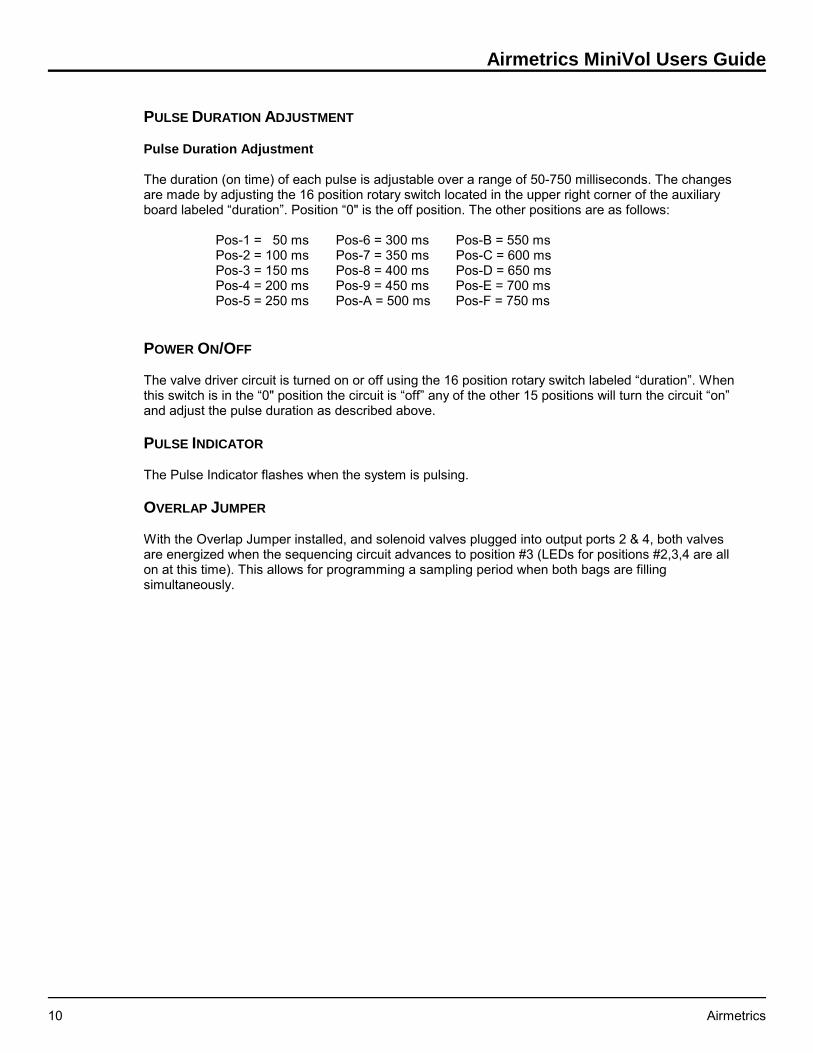
PULSE DURATION ADJUSTMENT
Pulse Duration Adjustment
The duration (on time) of each pulse is adjustable over a range of 50-750 milliseconds. The changesare made by adjusting the 16 position rotary switch located in the upper right corner of the auxiliaryboard labeled “duration”. Position “0" is the off position. The other positions are as follows:
Pos-1 = 50 ms Pos-6 = 300 ms Pos-B = 550 msPos-2 = 100 ms Pos-7 = 350 ms Pos-C = 600 msPos-3 = 150 ms Pos-8 = 400 ms Pos-D = 650 msPos-4 = 200 ms Pos-9 = 450 ms Pos-E = 700 msPos-5 = 250 ms Pos-A = 500 ms Pos-F = 750 ms
POWER ON/OFF
The valve driver circuit is turned on or off using the 16 position rotary switch labeled “duration”. Whenthis switch is in the “0" position the circuit is “off” any of the other 15 positions will turn the circuit “on”and adjust the pulse duration as described above.
PULSE INDICATOR
The Pulse Indicator flashes when the system is pulsing.
OVERLAP JUMPER
With the Overlap Jumper installed, and solenoid valves plugged into output ports 2 & 4, both valvesare energized when the sequencing circuit advances to position #3 (LEDs for positions #2,3,4 are allon at this time). This allows for programming a sampling period when both bags are fillingsimultaneously.

Section 4: Particulate Matter Sampling
Airmetrics 11
4: PARTICULATE MATTER SAMPLING
Sampling procedures for TSP, PM10, and PM2.5 are identical except for the configuration of thepreseparator/filter holder assembly.
Consumables
During particulate matter sampling, the following consumables are needed for proper operation of theMiniVol:
! Impactor grease - Glisseal® Ht, Apiezon® M Grease, etc.! Solvent to mix with grease - hexane, white gas, lantern gas, etc.! 47 mm filters - pure quartz, pure Teflon®, Teflon®-coated glass, etc.! Petri slides - for storage and transport of the filters.
A microbalance accurate to one microgram is needed to weigh the filters.
Airmetrics offers all of the above consumables (except the solvent), along with filter weighing services.
Siting Requirements
Siting recommendations in this manual conform to the U. S. Environmental Protection Agencyrequirements as stated in the U. S. Code of Federal Regulations (40 CFR part 58, Appendix E). Whenoperating the sampler in locations under another jurisdiction, the operator should follow theappropriate guidelines.
The MiniVol should be positioned with the intake upward and should be located in an unobstructedarea at least 30 cm from any obstacle to air flow. Accessibility to the unit under all weather conditions,along with safety and security of the monitoring personnel and equipment, should be primeconsiderations.
Attaching the Mounting Cradle
The MiniVol Mounting Cradle is designed to mount onto a standard 1 1/4 inch antenna mast orcomparable metal tubing (not supplied with the sampler). The mast should be strapped securely tosome other suitable structure)utility pole, parking meter, fence post, etc. (See Figure 4.1). Availableseparately from Airmetrics is a Y-Bracket Assembly which attaches to poles and provides a mast forthe mounting cradle. (Also shown in Figure 4.1).
Preparing the Sampler
If the sampler is equipped with a valve driver board for integrated gas sampling, make sure to turn offthe power on the auxiliary board before sampling unless integrated gas samples will be collectedsimultaneously with the particulate matter samples (refer to Section 5, “Integrated Gas Sampling”, forproper sampler preparation for gas sampling). This is accomplished by turning the “duration” rotaryswitch on the board to the “0" position. Be sure that the tubing conforms to the arrangement shown inFigure 4.2 (if a valve driver board is not attached) or Figure 5.1 (if a valve driver board is attached).
TSP - Remove the impactor from the preseparator/filter holder assembly prior to sampling. Sincethe impactor will not be used, greasing and cleaning of the impactor’s target disk need not bedone.

Airmetrics MiniVol Users Guide
12 Airmetrics
Figure 4.1. Mounted Sampler
PM10 - Use a PM10 impactor in the preseparator/filter holder assembly (see Figure 4.3). Greasingand cleaning of the impactor’s target disk should be performed initially and after every seventhsample (or more often if heavy loading is observed). Refer to Section 7, Maintenance, “ImpactorCleaning.”
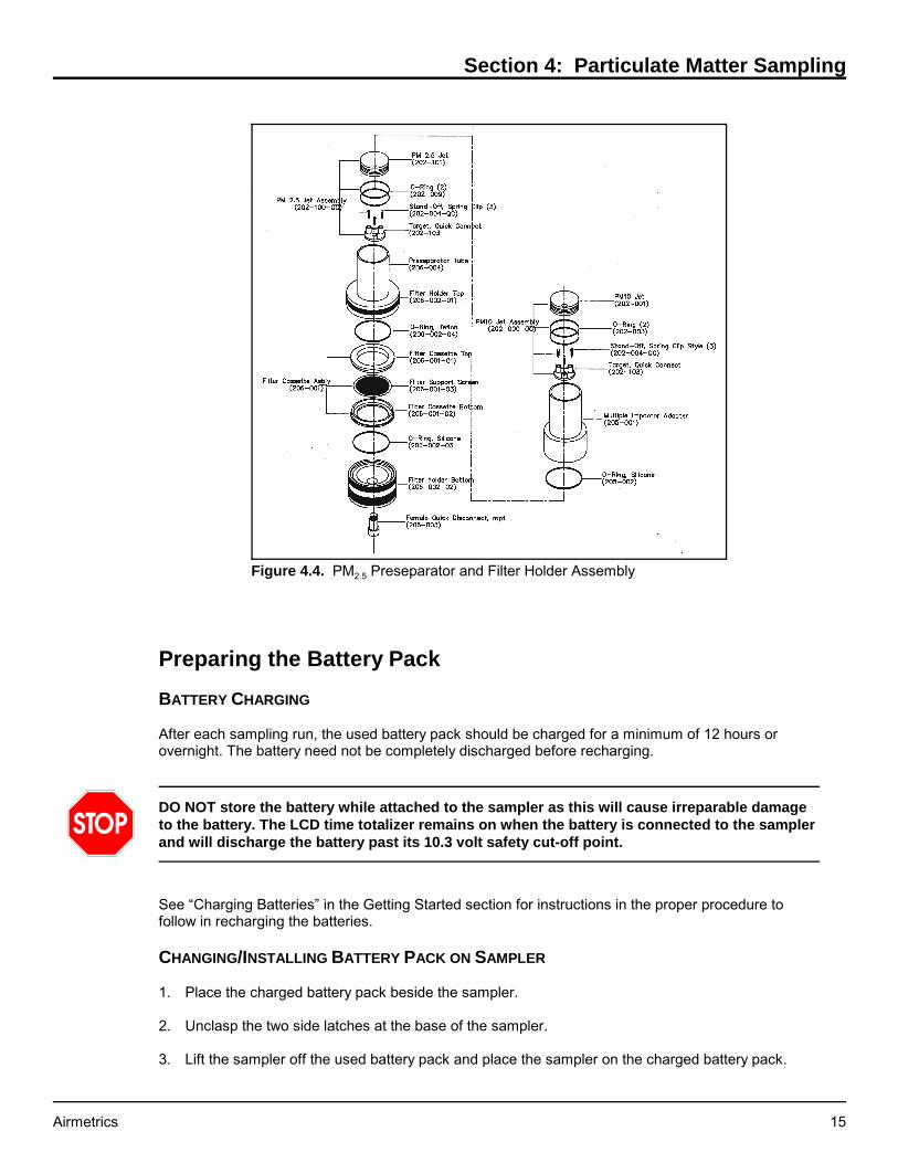
PM2.5 - Use a PM2.5 impactor in the preseparator/filter holder assembly and a PM10 impactor in amultiple impactor adapter mounted on the preseparator assembly tube (see Figure 4.4). Greasingand cleaning of the impactors’ target disks should be performed initially and after every seventhsample (or more often if heavy loading is observed). Refer to Section 7, Maintenance, “ImpactorCleaning.”
To remove impactors, use your thumb to simply push the impactor out of its tube from bottom to top.When correctly installed, the impactor’s top is flush with the surrounding preseparator tube or multipleimpactor adapter tube.

Section 4: Particulate Matter Sampling
Airmetrics 13
Figure 4.2. Tubing Configuration for PM Sampling Mode
Before transporting the MiniVol to the field, perform a laboratory check to determine if it is operational.Turn the sampler on and observe the motor performance. Check all tubing for crimps, cracks orbreaks. Perform a leak check followed by a flow check with a "dummy" filter in place to simulate theload against the sampler pump. Investigate and correct any malfunctions before proceeding. Performa single-point flow rate check using a calibrated orifice, soap-bubble meter or other flow measuringdevice of known accuracy and compare to the curve established during calibration. The flow shouldbe within ±10% of 5 lpm at current conditions. If the unit fails to operate in this range, check thesampler for obvious leaks and malfunctions. The sampler must be repaired or recalibrated if the flowcriteria are not met.
FLOW RATE
The particle size cut point of the preseparator is a function of the velocity with which the air stream asit passes through the preseparator and impacts on the target. The preseparator is designed to havethe correct cut point at an air flow rate of 5 lpm at ambient conditions. Since the density of air and thebehavior of the flowmeter are functions of the ambient air temperature and atmospheric pressure, aflow rate set point must be calculated for each different sampling project.
The sampler air flow calibration curves that are supplied with each sampler contains the necessaryinformation needed to determine the flowmeter set point for a particular ambient condition. Appendix Acontains the complete instructions in calculating the flow set points.
FLOWMETER CALIBRATION
The sampler should be recalibrated once a year and if the flowmeter or the pulse dampener arereplaced.

Airmetrics MiniVol Users Guide
14 Airmetrics
Figure 4.3. PM10 Preseparator andFilter Holder Assembly
Preseparator/Filter Holder Assembly
Depending on the required particle size separation, the configuration of the Preseparator changes.The attached Filter Holder Assembly contains a filter cassette in which the 47mm filter is supported bya filter support screen (see Figure 4.3 for PM10 and Figure 4.4 for PM2.5).
CLEAN AND GREASE IMPACTOR
Initially, and after every seventh sample, the impactor target should be cleaned and greased under alaboratory fume hood (preferably) or any well ventilated area (including on-site). The cleaningfrequency can be increased or decreased depending on the ambient loadings and degree of soilingobserved on the target disk.
For Impactor cleaning procedures, see Section 7, Maintenance, "Impactor Cleaning."
INSTALLING FILTERS
This procedure should take place in a laboratory or otherclean area. Contact with and handling of all filters shouldbe limited to the edges of the filters. Also, the use of non-serrated, Teflon®-tipped forceps is stronglyrecommended. Filters should be kept in protective petrislides. Filters must never be bent or folded.
1. Select a filter and remove cover from petri slide.
2. Using forceps, install the new filter into the filtercassette.
3. Place the filter cassette in the filter holder.
4. Replace preseparator adapter and screw downsnugly.
5. Place an identifying tag on the filter holder so that theID number of the filter mounted in the holder isknown.
6. Place a clean, plastic bag over the top of thepreseparator adapter inlet and push the rain capsnugly into place over the bag.
7. Place the entire clean filter assembly into a secondplastic bag, or other case, for transporting to the site. It is best to keep the filter assembly in avertical position until installed on the sampler.
Section 4: Particulate Matter Sampling
Airmetrics 15
Figure 4.4. PM2.5 Preseparator and Filter Holder Assembly
Preparing the Battery Pack
BATTERY CHARGING
After each sampling run, the used battery pack should be charged for a minimum of 12 hours orovernight. The battery need not be completely discharged before recharging.
DO NOT store the battery while attached to the sampler as this will cause irreparable damageto the battery. The LCD time totalizer remains on when the battery is connected to the samplerand will discharge the battery past its 10.3 volt safety cut-off point.
See “Charging Batteries” in the Getting Started section for instructions in the proper procedure tofollow in recharging the batteries.
CHANGING/INSTALLING BATTERY PACK ON SAMPLER
1. Place the charged battery pack beside the sampler.
2. Unclasp the two side latches at the base of the sampler.
3. Lift the sampler off the used battery pack and place the sampler on the charged battery pack.

Airmetrics MiniVol Users Guide
16 Airmetrics
Note: The pin on the sampler closest to a side clip inserts into the odd colored receptacle on thebattery pack (see Figure 2.1).
4. Reclamp the two side latches.
OTHER BATTERY CHECKS
A single AA battery on the circuit board operates the Programmable Timer. The lifetime for this batteryis approximately six months when it is left in place on the circuit board. Be sure to observe the correctpolarity when inserting a new AA battery into the battery compartment.
Refer to Section 8, “Troubleshooting” for additional comments on battery functions.
Setting the Desired Sampling Time
Determine the time of the day when the sampler is to turn on and off. Program the timer to turn thesampler on and off at these times (see "Programming the Timer" in Section 2).
Particulate Matter Sampling Procedure
After the sampler has been assembled, adjusted, verified to be in proper working order, and a filterloaded in the Filter Assembly, the sampler is ready to collect air samples. Note: For a quick referenceto the following steps, see "Particulate Matter Sampling Routine at Site" (Appendix C). If a gas sampleis also to be collected simultaneously, refer to Section 5, “Integrated Gas Sampling” for proper gassampling procedures.
1. Carefully transport the sampler to the field site. Verify that the sampler, when finally installed in themounting cradle, will be positioned with the intake upward in an unobstructed area at least 30 cmfrom any obstacle to air flow.
2. Place the sampler on a firm level surface.
3. Remove the clean Preseparator/Filter Holder Assembly from the plastic transport bag and removethe protective plastic bag under the rain cap. Attach the assembly to the sampler top at the quickconnect.
4. Record the following information on the PM Field Data Sheet: number of the filter, the battery ID,sampler ID, ambient temperature and pressure, flowmeter reading, and elapsed time meterreading. (a copy of the data sheet may be downloaded from the Airmetrics website,www.airmetrics.com).
5. While depressing the snap buttons lift the pump and timer assembly out by the 6" diameter topcap and rest it on the edge of the sampler casing, using the triangular pump mount stand. Takecare not to pull the connecting wire loose or jar the pump hose fittings. Hold the top cap and doNOT grasp the center of the circuit board.
6. To obtain the beginning flow rate, press the ON/AUTO/OFF button to start the pump. On the LCDdisplay, the horizontal bar should move to "ON".
7. If the flowmeter, which should be in the vertical position, indicates zero or a very low reading,check for restrictions in the tubing, or improperly seated screw fittings between the pump and theflowmeter.
8. Using the Flow Rate Adjustment control (see Figure 3.1), set the flowmeter flow withinspecifications for the project temperature and pressure conditions. Take the reading of theflowmeter from the center of the ball. (See Section 3, page 8, Flow Rate Adjustment for details).

Section 4: Particulate Matter Sampling
Airmetrics 17
9. Press the ON/AUTO/OFF button twice to stop pump.
10. Press the ON/AUTO/OFF button to set the timer to "Auto" mode. The Sampler MUST be in “Auto”mode before the operator leaves.
11. Place the pump and timer assembly back into the sampler body and secure snap buttons.
12. Using the hoisting pole, hook the bale assembly bar and raise the sampler, as vertically aspossible, to the mounting cradle. This position not only more easily accommodates the sampler'sweight, but prevents the hook from hitting and possibly dislodging or breaking thepreseparator/filter holder assembly. (See Figure 4.1).
Particulate Matter Sample Retrieval
As soon as possible after the end of the sampling period, the operator should return to the monitoringsite to retrieve the exposed filter. Potential for filter damage or changes in sample mass due to particleloss, passive deposition, or volatilization increases if the filter is left in the sampler for extendedperiods. On the Field Data Sheet record the ambient temperature (Ta), barometric pressure (Pa),flowmeter reading and elapsed time.
Note: Ta and Pa readings may be estimated on site or may be obtained from a nearby US NationalWeather Service Forecast Office or airport weather station. Barometric pressure readings obtainedfrom airports must be at station pressure (not corrected to sea level), and they may have to becorrected for differences between the elevation of the monitoring site and that of the airport. If Ta andPa readings are not available, seasonal average temperature (Tavg) and barometric pressure (Pavg)may be substituted. Care must be taken that the actual conditions at the site can be reasonablyrepresented by such averages. It is therefore recommended that seasonal values represent actualvalues within 20 °C and 40 mm Hg.
Note: If a gas sample is also being retrieved, refer to Section 5 “Integrated Gas Sampling” for propergas sample retrieval.
1. Remove the sampler from the mounting cradle using the hoisting pole. Position yourself directlyunder the sampler, hook the bale assembly bar, and lower the sampler as vertically as possible.This vertical take-away not only accommodates the sampler's weight, but prevents the hook fromdislodging the rain cap or damaging the preseparator/filter holder assembly (see Figure 4.1).
2. Place the sampler on a firm level surface.
3. While depressing the snap buttons lift the pump and timer assembly out by the 6" diameter topcap and rest it on the edge of the sampler casing, using the triangular pump mount stand. Takecare not to pull the connecting wire loose or jar the pump hose fittings. Hold the top cap and doNOT grasp the center of the circuit board.
4. Lift the pump and timer assembly out by the top cap and rest it on the edge of sampler body usingthe triangular mount stand. Take care not to pull the connecting wire loose and hold the top cap.
5. Check the sampler face plate for any error conditions. If an error conditions exists, refer to the“Error Conditions” section at the end of this chapter.
6. Verify correct time and day of week on time LCD.
7. Record elapsed time as shown on the Elapsed Time Totalizer.
8. Obtain ending flow rate:

Airmetrics MiniVol Users Guide
18 Airmetrics
! Press the ON/AUTO/OFF button twice to start the pump.
! With the flowmeter in a vertical position, record flow rate to the nearest 10th of liter/minute(read at center of ball).
! Press the ON/AUTO/OFF button twice to stop the pump.
9. Place the pump and timer assembly into the sampler body.
10. Exchange a new preseparator/filter holder assembly for the exposed filter holder assembly. Ifpossible, perform the exchange inside a building or vehicle to minimize exposure to the elements.Perform a cross-check of the exposed filter number with the filter number recorded on the FieldData Sheet for the run just completed. Also, check the filter number against the site number.
11. Change Battery Pack (see page 15)
12. Obtain beginning flow rate (see above, step 8).
13. Make sure the timer is set for the desired period and in the “AUTO” mode.
14. Place the pump and timer assembly back into sampler body and secure snap buttons.
15. Using the hoisting pole, hook the bale bar and raise the sampler, as vertically as possible, to themounting cradle.
EXPOSED FILTER
1. In the laboratory, unscrew the filter holder and remove the filter cassette.
2. Locate the petri slide with the filter number which matches the number on the side of the filterholder assembly. This is the original petri slide in which the filter came.
3. Use the cassette separator (P/N 600-007) to remove the top half of the filter cassette.
4. Using forceps, carefully remove the exposed filter from the filter cassette and place it into itsoriginal petri slide, replacing the petri slide lid when finished. (Be sure to replace the filter supportscreen in the filter cassette assembly).
5. Remove the old ID tag from the filter holder assembly base and discard. (Recheck this number tobe sure it matches the number on the petri slide.)
ERROR CONDITIONS
Low Battery Indicator ON
Should the Low Battery Indicator be ON at the end of a sampling period, check the Elapsed TimeTotalizer to determine the length of time the sampler ran before shutting off. If the time is short (e.g.,only 2 hours out of a programmed 8 or 10 hours), perhaps the battery was not completely charged oris failing to hold a charge. Note the battery number and, after recharging in the lab, observeperformance in the next sampling period. If the battery fails again, it is most likely defective and shouldbe replaced.
If a different battery performs in the same manner after shown to be fully charged, the pump motor isperhaps drawing more current than it should. If possible, install a pump from another sampler. If thissolves the problem, the previous pump motor is likely defective and should be replaced. If the problemcontinues, a more serious fault is occurring which should be referred to Airmetrics (see Appendix D).

Section 4: Particulate Matter Sampling
Airmetrics 19
Low Flow Indicator ON
Should the Low Flow Indicator be found ON at the end of sampling period, first check the ElapsedTime Totalizer to determine the length of time the sampler ran before shutting off. The possiblecauses for low flow are:
! Low Battery: Although power did not fall to the 10.3V lower limit that would shut down thesystem, the pump may not have been receiving enough voltage to maintain the desired air flow.This will usually only occur if the pump needs to be rebuilt or replaced.
! Air Restriction: If the battery is sound, the problem may be due to a restriction in the air inlet,filter holder, or tubing. Check for crimps or other possible restrictions. Also, a broken or loosetubing fitting on the outlet side of the pump could cause a low flow condition. It is also possible forexcessive moisture on the filter (rain, condensation) to cause enough flow resistance for the LowFlow Indicator to come on.
! Pump Malfunction: The low flow condition could be the result of decreased pump efficiency,which is usually caused by damaged or contaminated pump head components (valves,diaphragms). Check to see if the pump can maintain a free (unrestricted) airflow rate of at least 5lpm. If not, see Section 7 for pump maintenance instructions.
Overriding Low Flow/Low Battery Indicators
When Low Flow and Low Battery Indicator lights are on, the system can be restarted by pressing theReset Button. The system will usually run enough to perform a brief field inspection and to obtain finalflow rates.

Airmetrics MiniVol Users Guide
20 Airmetrics
This page was intentionally left blank.

Section 5: Integrated Gas Sampling
Airmetrics 21
5: INTEGRATED GAS SAMPLING
MiniVol sampling procedures for all non-reactive gases are the same. It should also be noted that theMiniVol simply collects a gas sample. Analyzing a gas sample must be done separately with theproper gas analyzing equipment.
Consumables
No consumables are needed except for the occasional replacement Tedlar® bag should one becomedamaged. Contact Airmetrics for replacement bags.
Siting Requirements
Siting recommendations in this manual conform to the U. S. Environmental Protection Agencyrequirements as stated in the U. S. Code of Federal Regulations (40 CFR part 58, Appendix E). Whenoperating the sampler in locations under another jurisdiction, the operator should follow theappropriate guidelines.
As with particulate matter sampling, the MiniVol should be positioned with the intake upward andlocated in an unobstructed area at least 30 cm from any obstacle to air flow. Accessibility to the unitunder all weather conditions, along with safety and security of the monitoring personnel andequipment, should be prime considerations.
Attaching the Mounting Cradle
Mount the MiniVol cradle onto a standard 1 1/4 inch Tripod mast or comparable metal tubing, whichitself is strapped securely to another supporting structure)utility pole, parking meter, fence post, etc.(see Figure 4.1).
Preparing the Sampler
To collect integrated gas samples, the sampler must be fitted with the optional valve driver board. Ifyour original order specified integrated gas sampling attachments, the sampler arrived prefitted forgas sampling. To prepare for the gas sampling, you need only change the bale bar and handle, attachthe bag canisters, and turn on the Valve Driver Board. However, if you wish to retrofit the sampler forintegrated sampling, you must make several minor modifications to the sampler body and controlboard. (Contact Airmetrics for parts and information on this procedure). The gas sampling tubingconfiguration is illustrated in Figure 5.1.
OPERATION MODES - STANDARD MODE OR OVERLAP MODE
In Standard Mode the sampler can be set to take samples at different times during which either oneor two bags can be filled. In this mode, only one bag can be filled during a given period.
To operate in Standard Mode:
! Plug the solenoids into desired positions 1-4.
! Remove Overlap Jumper.
! With the sampler off, advance to desired starting channel with Manual Advance Button.
! Set timer as desired.
Airmetrics MiniVol Users Guide
22 Airmetrics
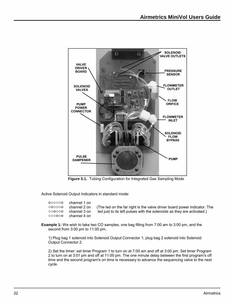
Figure 5.1. Tubing Configuration for Integrated Gas Sampling Mode
Active Solenoid Output Indicators in standard mode:
'""""' channel 1 on"'"""' channel 2 on (The led on the far right is the valve driver board power indicator. The ""'""' channel 3 on led just to its left pulses with the solenoids as they are activated.)"""'"' channel 4 on
Example 1: We wish to take two CO samples, one bag filling from 7:00 am to 3:00 pm, and thesecond from 3:00 pm to 11:00 pm.
1) Plug bag 1 solenoid into Solenoid Output Connector 1; plug bag 2 solenoid into SolenoidOutput Connector 2.
2) Set the timer: set timer Program 1 to turn on at 7:00 am and off at 3:00 pm. Set timer Program2 to turn on at 3:01 pm and off at 11:00 pm. The one minute delay between the first program's offtime and the second program's on time is necessary to advance the sequencing valve to the nextcycle.

Section 5: Integrated Gas Sampling
Airmetrics 23
Example 2: We wish to take two CO samples (from 7:00 am to 3:00 pm, and from 3:00 pm to 11:00pm) while also collecting a PM10 sample from 1:00 am to 11:00 pm.
1) Plug bag 1 solenoid into Solenoid Output Connector 2; plug bag 2 solenoid into SolenoidOutput Connector 3.
2) Set the timer:
a) Set timer Program 1 to turn on at 1:00 am and off at 7:00 am. During this program, neitherbags will be filled but air will be drawn through the PM10 filter.
b) Set timer Program 2 to turn on at 7:01 am and off at 3:00 pm. Air will be drawn through thefilter and bag 1 will be filled.
c) Set timer Program 3 to turn on at 3:01 pm and off at 11:00 pm. Air will be drawn throughthe filter and bag 2 will be filled during this programmed step.
In Overlap Mode the sampler can be set to overlap the sampling periods for the bags. For example;the operator could set the sampler to collect air in one bag from 10:00 am to 6:00 pm and in the otherbag from 3:00 pm to 11:00 pm. During the overlapping period from 3:00 pm to 6:00 pm the samplewould be collecting air in both bags simultaneously.
To operate in Overlap Mode:
! Plug solenoids into positions 2 & 4.
! Place the Overlap Jumper on the pins.
! With the sampler off. Advance to channel 2 with Manual Advance Button.
! Set timer as desired.
Active Solenoid Output Indicators in Overlap Mode:
'""""' channel 1 on"'"""' channel 2 on"'''"' channels 2 & 4 on"""'"' channel 4 on
Example 3: We wish collect air in one bag from 10:00 am to 6:00 pm and in the other bag from 3:00pm to 11:00 pm.
1) Place the Overlap Jumper on the pins.
2) Plug bag 1 solenoid into Solenoid Output Connector 2; plug bag 2 solenoid into SolenoidOutput Connector 4.
3) Set the timer:
a) Set timer Program 1 to turn on at 10:00 am and off at 3:00 pm. During this program, bag 1 willbe filling.
b) Set timer Program 2 to turn on at 3:01 am and off at 6:00 pm. During this program, bothsolenoids will be active and both bags will be filling simultaneously.
c) Set timer Program 3 to turn on at 6:01 pm and off at 11:00 pm. During this programmed step,only bag 2 will be filling.
Airmetrics MiniVol Users Guide
24 Airmetrics
ADJUSTING PULSE FREQUENCY AND DURATION
The rate at which the bags are filled is set by using a tunable intervalometer or pulse circuit which canbe adjusted both for frequency (continuously on to 1 pulse in 15 seconds) and for duration (50 ms to750 ms). The pulse frequency is controlled by the Intervalometer Frequency Adjustment, while theduration of each pulse is set by the Pulse Duration Adjustment.
Adjusting the pulse circuit using the Intervalometer Frequency Adjustment and the Pulse DurationAdjustment is accomplished through trial and error. A test period in the laboratory is therefore requiredbefore the sampler can be moved to the field site. The object is to achieve a combined pulse durationand interval that will integrate a sample of air over the programmed period of time. At the end of theprogrammed period the bags should be 80-90% filled. That is, the bag should not be tightly filled,since there would be no way of knowing at what point the bag became filled.
The pulse duration and frequency controls can be adjusted to suit the requirements of the task athand. For example; one can take many small samples or a few large samples over the same period oftime depending on the needs of the operator.
Pulse Interval Adjustment
The pulse interval (off time) of the circuit is adjustable over a range of 0-15 seconds by a 16-positionrotary switch. This switch is located just to the right of the solenoid valve output connectors and islabeled “interval”. Switch positions are marked clockwise 0-9, and continue A-F. The interval betweenpulses increases in 1-second increments as the switch is rotated in a clockwise direction. Position"0" activates the solenoids and leaves them in that state (this will allow the bag or bags to befilled as fast as the sampler flow rate allows). Position "1" corresponds to a minimum delay time ofone pulse per second, and position "F" indicates the maximum delay of 15 seconds between pulses.
Pulse Duration Adjustment
The duration (on time) of each pulse is adjustable over a range of 50-750 milliseconds. The changesare made by adjusting the 16 position rotary switch located in the upper right corner of the auxiliaryboard labeled “duration”. Position “0" is the off position. The other positions are as follows:
Pos-1 = 50 ms Pos-6 = 300 ms Pos-B = 550 msPos-2 = 100 ms Pos-7 = 350 ms Pos-C = 600 msPos-3 = 150 ms Pos-8 = 400 ms Pos-D = 650 msPos-4 = 200 ms Pos-9 = 450 ms Pos-E = 700 msPos-5 = 250 ms Pos-A = 500 ms Pos-F = 750 ms
Example: Suppose you wish to fill a 6 liter bag over a period of 4 hours. The first step would be todetermine the amount of air pumped during a single pulse. This can be done by replacing the bag atthe mini quick-connect with a bubble flow meter, and starting the pump in the gas sampling mode. If 1cc of air was pumped during a single pulse, a 10 second interval between pulses would result in 6 ccbeing pumped per minute, or 360 cc per hour, or 1440 cc over four hours. Since this amount fallsconsiderably short of 6 liters, the pulse duration and/or frequency would have to be increasedaccordingly.
In this manner, calculate an approximate pulse duration and pulse frequency for the test period.
NOTE: New samplers are factory calibrated to deliver approximately a 1.2 cc per pulse every 7seconds. This should fill a 6 liter tedlar bag to about 80% capacity in 8 hours.

Section 5: Integrated Gas Sampling
Airmetrics 25
Preparing the Sampler
1. Attach a new battery pack.
Important Note: The Valve Sequencing Board automatically resets when the sampler's mainpower is interrupted. Consequently, the battery must be changed before setting thesequencing circuit.
2. Unscrew either cap of the bale assembly bar and remove the bale assembly.
3. Disconnect canister tubing and remove the canisters.
4. Depress the snap buttons and lift the pump and timer assembly out by the 6" diameter top capand support the mounting board on the edge of the sampler casing using the pump mount standand taking care not to pull the connecting wire loose. Hold the top cap and do not grasp the centerof the circuit board. Leave the battery attached.
5. Set the calculated pulse duration for the test period with the Pulse Duration Control.
6. Set the interval between pulses to the calculated setting by turning the Intervalometer IntervalAdjustment. The control is marked 0-9 then A-F where zero is continuous pulsing and F is onepulse every 15 seconds.
7. Turn on the valve sequencer board by moving the duration rotary switch to the desired pulseduration. Position “0" is the “off” position.
8. Set the Valve Driver Board to either standard or overlap mode using the Overlap Jumper.
9. Program the timer for the desired test period.
10. Set the timer to "Auto" to begin the test period.
11. Replace the pump and timer assembly into sampler body. Replace the 6" cap, the bale assemblybar, and the canisters. Reattach the canister tubing.
12. At the end of the test period, increase or decrease the pulse frequency or pulse durationdepending on the fullness of the bags.
13. When test results are within adequate limits, attach new battery pack and move sampler to fieldsite.
Airmetrics MiniVol Users Guide
26 Airmetrics
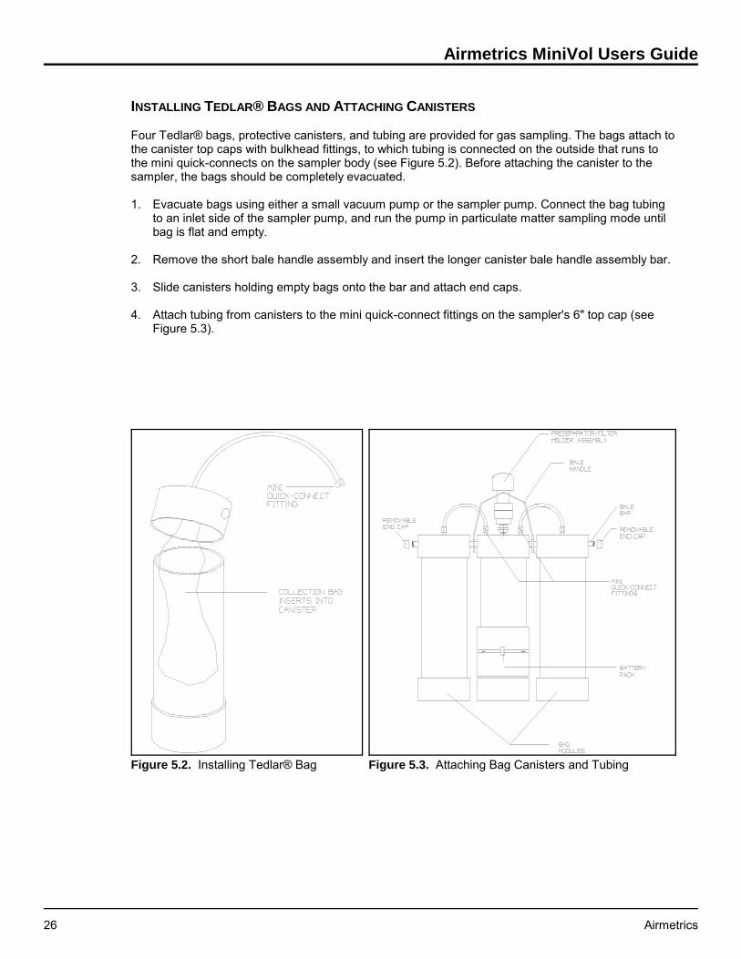
Figure 5.3. Attaching Bag Canisters and TubingFigure 5.2. Installing Tedlar® Bag
INSTALLING TEDLAR® BAGS AND ATTACHING CANISTERS
Four Tedlar® bags, protective canisters, and tubing are provided for gas sampling. The bags attach tothe canister top caps with bulkhead fittings, to which tubing is connected on the outside that runs tothe mini quick-connects on the sampler body (see Figure 5.2). Before attaching the canister to thesampler, the bags should be completely evacuated.
1. Evacuate bags using either a small vacuum pump or the sampler pump. Connect the bag tubingto an inlet side of the sampler pump, and run the pump in particulate matter sampling mode untilbag is flat and empty.
2. Remove the short bale handle assembly and insert the longer canister bale handle assembly bar.
3. Slide canisters holding empty bags onto the bar and attach end caps.
4. Attach tubing from canisters to the mini quick-connect fittings on the sampler's 6" top cap (seeFigure 5.3).

Section 5: Integrated Gas Sampling
Airmetrics 27
Integrated Gas Sampling Procedure
After the sampler has been assembled, the pulse frequency and duration correctly establishedthrough a test run, and a fresh battery installed, the sampler is ready to collect air samples at a fieldsite.
NOTE: If a particulate sample is being collected simultaneously, refer to Section 4, “Particulate MatterSampling” for proper particulate sampling procedure.
1. Transport the sampler to the field site. Verify that the sampler when installed in the cradle will bepositioned with the intake upward in an unobstructed area at least 30 cm from any obstacle to airflow.
2. With the sampler on a firm level surface, unscrew either cap of bale assembly bar and removebale assembly.
3. Detach canister tubing at mini quick-connect fittings and remove canisters.
4. Depress the snap buttons and lift pump and timer assembly out by the 6" diameter top cap andsupport the mounting board on the edge of the sampler casing, taking care not to pull theconnecting wire loose or jar the pump hose fittings. Hold the control assembly by the top cap anddo NOT grasp the circuit board.
5. Check that the Valve Driver Board is operational (Active Solenoid Output Indicators on).
6. Verify that all hose connections are secure. Check the sampler pump and flow by turning it on andthen off.
7. Select the desired mode of operation (standard or overlap) with the Overlap Jumper. Make surethat the solenoid valves are plugged into the correct output connectors.
8. Use the Manual Sequence Advance Button to select the required channel.
Important Note: The Valve Sequencing Board automatically resets when the sampler's mainpower is interrupted. This is why the battery must be changed before setting the sequencingcircuit.
9. Program the on/off cycles for the desired sampling period (see page 5).
10. Press the ON/AUTO/OFF button once to set the timer to "Auto" mode. The sampler must be inAuto mode before the operator leaves.
11. Place pump and timer assembly into sampler body and secure snap buttons. Replace baleassembly bar and canisters, and connect tubing.
12. Using the hoisting pole, hook the bale and raise the sampler as vertically as possible to themounted mounting cradle (see Figure 4.4).
Gas Sample Retrieval
As soon as possible after the end of the sampling period, the operator should return to the monitoringsite to retrieve the filled bags. If a particulate sample is being collected simultaneously, refer to Section4, “Particulate Matter Sampling” for proper particulate sample retrieval procedures.

Airmetrics MiniVol Users Guide
28 Airmetrics
Note: For a quick reference to the following steps, see Appendix C, "Integrated Gas SamplingRoutine at Site."
1. Lower sampler from cradle using the hoisting pole. Positioned directly under the sampler, hookbale handle and lower away as vertically as possible. This vertical take-away is critical since thehook may dislodge or damage the rain cap or sampler head. Also, the weight is more easilymanaged if the sampler is lowered vertically (see Figure 4.4).
2. With the sampler on a firm level surface, unscrew either cap of the bale assembly bar and removebar assembly. Detach canister tubing at the mini quick-connect fittings and remove canisters.
3. Depress the snap buttons and lift the pump and timer assembly out by the top cap and rest on theedge of the sampler body, taking care not to pull the connecting wire loose. Hold the top cap. DoNOT grasp the circuit board.
4. Verify correct time and day of week on time LCD.
5. Record elapsed time as shown on the elapsed time accumulator, which should match theprogrammed time set at the beginning of the sampling period.
6. Check and record the fullness of the bag(s), adjusting the pulse interval or duration if necessary.
7. Program timer for new sampling period (see page 5).
8. Set to "Auto" mode.
9. Change battery pack (see page 15).
Important Note: The Valve Sequencing Board automatically resets when the sampler's mainpower is interrupted. This is why the battery must be changed before setting the sequencingcircuit.
10. Check the Active Solenoid Output Indicators to make sure that the desired starting channel hasbeen selected. Use the Manual Sequence Advance Button to select the required channel ifnecessary.
11. Lower pump and timer assembly into sampler body and secure snap buttons.
12. Replace bale bar assembly, attach new canisters, and connect tubing.
13. Using the hoisting pole, hook the bale handle and raise the sampler to the mounting cradle asvertically as possible.

Section 6: Hardware Description
Airmetrics 29
6: HARDWARE DESCRIPTION
Pneumatic System
PNEUMATIC SYSTEM FLOW SCHEMATIC
See Figure 6.1.
FILTER HOLDER ASSEMBLY
A 47 mm diameter filter cassette and filter holder assembly is used to hold the filter media.
FLOWMETER
A standard flowmeter with a range of 1 to 10 lpm is used to indicate sampling flow rate. Theuncalibrated accuracy of the flowmeter is ±4% of full scale.
FLOW CONTROL SYSTEM
A monitoring system designed by Airmetrics electronically controls pump speed to maintain aspecified flow setting by measuring the drop in air pressure at the outlet of the flowmeter. The FlowControl System is temperature compensated for reasonable changes in ambient temperature andpressure.
MINIATURE D.C. DOUBLE DIAPHRAGM PUMP
The pump has two pumping sections or heads that are connected in parallel for increased flow. Thepumping sections consist of synthetic rubber diaphragms and valves driven from the motor shaft by ayoke-crank assembly. All moving parts are completely enclosed. The service life of the motor is inexcess of 10,000 hours continuous duty. The diaphragm and valve assemblies are easily replaceable.The service life expectancy of these assemblies are a function of the environmental conditions,including the gases being pumped, delivery rate, and back pressure. Minimum service life for thepumping sections is on the order of 5000 or more hours continuous duty.
The motor generates no radio frequency interference and all electronic components are containedwithin the motor housing.

Airmetrics MiniVol Users Guide
30 Airmetrics
Figure 6.1. Pneumatic System Flow Schematic
Electronics System
MOTHERBOARD
Virtually all sampler components connect to the motherboard: the pump, programmable timer,elapsed time totalizer, flowmeter, and flow control components. Flow control and fault circuits, are builtinto this board, and pins are provided on the back side to mount the valve driver board for dual bagsampling.

Section 6: Hardware Description
Airmetrics 31
POWER SUPPLY
The sampler is powered by removable battery packs which contain a 12 volt, 12 amp-hour sealedlead-acid battery. The separate charger is designed to quick-charge the battery and then switch to a"maintenance" mode to avoid an overcharge condition. The charger can be left on for an indefiniteperiod without damaging the battery.
PROGRAMMABLE TIMER
The Programmable Timer can switch power on and off up to 6 times per day over a 7-day period andis capable of individual or multi-day timer settings. It has an easy to read liquid-crystal display and ispowered by an on board AA battery.
FLOW CONTROLLER CIRCUIT
The Flow Controller Circuit is designed to maintain a constant pressure drop across an orifice at theoutput of the flowmeter. Feedback from the pressure sensor is used to control the pump speed. Thesystem is temperature compensated and is capable of maintaining a constant volumetric flow ratewithin ±5% of the set point over the range of 0 to 40°C.
ELAPSED TIME TOTALIZER
The Elapsed Time Totalizer is a non-resetable time totalizer which is activated when theprogrammable time controller is in the "ON" mode. The meter totals hours and tenths of hours.
INTERCONNECT BOARD
The Interconnect Board is located in the bottom of the sampler case. Power from the battery pack isrouted through banana pins on the outside of the sampler bottom to the Interconnect Board. A phoneplug in jack and cable is used to connect power to the motherboard. A 2 amp fuse on the interconnectboard provides protection to the motherboard from short circuits and high current loads.

Airmetrics MiniVol Users Guide
32 Airmetrics
This page was intentionally left blank.

Section 7: Maintenance
Airmetrics 33
Figure 7.1. Regreasing PM2.5 Impactor
7: MAINTENANCE
Ideally, records reflecting the history of maintenance(including all replacement parts, supplies, costs,expenditures) should be kept for each MiniVol, along withan inventory of on-hand spare equipment.
Check sheets should be used to record preventativeand/or corrective maintenance activities and thesubsequent sampler calibration curve.
The sampler is comprised of four basic components:preseparator/filter holder assembly, flow control system,timer, and battery pack. Following are recommended,routine maintenance procedures for the sampler’s basiccomponents.
Preseparator/Filter Holder Assembly
IMPACTOR CLEANING
The preseparator/filter holder assembly should be dismantled and the impactor cleaned and greasedat regular intervals)i.e., every seventh sample to start, but if heavy loadings are observed on thetarget disk, as often as appropriate.
1. Unmate the preseparator sections from the filter assembly and remove the rain cap (see Figure4.3 and 4.4).
2. Pushing with the thumb from the bottom, remove the impactor through top of the tube into thepalm of your free hand.
3. Rinse the impactor from top to bottom with a solvent (hexane, white gas, lantern gas) using asqueeze bottle, paying particular attention to the impaction target disks. An acceptable alternativemethod of cleaning involves the use of an ultrasonic bath with mild soapy water solution.
Impaction plates on the impactor(s) should be removed prior to regreasing. The impaction plate isattached to the impactor jet by spring tension only and may be separated by simply pulling the jetfrom the impaction plate (see Figure 7.1).
4. Let the impactor air-dry.
5. Prepare a mixture of solvent and impactor grease in a dropper bottle until thoroughly mixed and ofa fluid consistency. Use a 1-inch length of grease to 30 ml of solvent. Vigorously shake themixture until an opaque, uniform (free from grease globs) suspension is obtained.
Other low-vapor pressure greases, such as silicone, are acceptable. However, removing the dirtygrease from the impactor parts may be more difficult.
6. Put two or three drops of the cloudy solution on the target disk. The drops should saturate thedisk, flowing freely to the edge.
7. Let the target disk "dry" by allowing the solvent to volatilize, leaving a thin film of grease on thetarget disk.

Airmetrics MiniVol Users Guide
34 Airmetrics
8. Inspect the O-rings on the impactor for fitness and replace if necessary. O-rings should be coatedwith a thin film of silicone lubricant prior to use. Remove any extraneous, loose, or hair-likeshredded material from the exterior of the impactor unit since this material could fall onto the filterbelow and cause erroneous gravimetric results. Carefully re-insert the impactor into the top of thepreseparator tube until the top of the impactor is flush with the top of the tube.
Flow Control System
Tubing, pulse dampener, and fittings must be routinely checked for crimps, cracks, or obstructions.Fittings should be inspected periodically for cross-threading and tightness. The flowmeter should becleaned or replaced if it indicates no flow, low flow, excessive flow, or erratic flow. The flowmeter canbe easily cleaned using warm water and detergent; follow the steps below:
1. Remove the inlet and outlet tubing and detach the flowmeter from the main circuit board.
2. Remove the flowmeter end caps and submerge in detergent solution. Slosh water back and forthusing the ball as a self-cleaning agitator. Follow with a rinse in clean water.
3. Air dry and reinstall.
Programmable Timer
A single AA alkaline battery powers the programmable timer. It should last at least 6 months. Sincethe clock and timer are sealed electronic devices, any failure requires replacement of the entire unit.
Battery Pack
Remove the battery pack top using a Phillips screwdriver and look for loose connections. The batterywiring and fuse harness should be securely clamped to the banana jacks and the push on wireconnectors securely attached to the battery. Open and check the fuse holder for any corrosion. Cleanand tighten any connections if corroded.
Cleaning/Inspecting Pump Valves and Diaphragms
After continued use, the pump valves and diaphragms will become dirty or worn. This conditionusually manifests as an irregular flow rate or an inability to accurately adjust the flow rate. The pumpmay be unable to achieve or sustain a maximum flow rate (above 6 lpm). When these conditionsoccur, the pump valves must be cleaned or replaced. While the pump diaphragms are not usuallyaffected by dirt, they will become worn and need replacement.
The side of the pump on which the valves are worn or dirty is easily determined by pinching the inlettubes leading to the pump (first one side and then the other). Under normal conditions, the flow ratewill drop by the same amount for both sides as the lines are restricted. If the flow rate drops less forone side, the valves on that side need cleaning or replacing.
When cleaning or replacing valves and diaphragms, replace or clean all valves and diaphragms. (A"Double Diaphragm Pump Rebuild Kit" can be obtained from Airmetrics.)
CLEANING/INSPECTING PUMP HEAD VALVES
1. Remove a pump head, making note of the orientation of the head and valves. Inspect and replaceany valves or diaphragm that are worn or damaged.
2. Clean the diaphragm and valves that are still in good working order with soapy water, rinse anddry. Flip each component and replace in the same order.

Section 7: Maintenance
Airmetrics 35
3. Screw on the pump head, taking care to match the alignment of the in flow and out flow ports oneach pump head.
4. Repeat for opposite side of the pump.

Airmetrics MiniVol Users Guide
36 Airmetrics
8: TROUBLESHOOTING
This section identifies common problems and the action necessary to correct them.
Problem Solution
The flowmeter will not zerowhen a leak check isperformed.
Prior to every sample run with the pumprunning, check for leaks by removing theinlet assembly and covering the quickconnect inlet with palm of the hand or afinger. The flowmeter should drop to zero. Ifnot, a leak is present. Check all tubings andfittings for cracks and tightness. Check thepump nozzle connections and the flowmeterfor cracks.
NOTE: when checking the fittings fortightness DO NOT use a wrench or othertool to tighten these connections. Thesefittings are made to be finger tightened. If aleak persists after finger tightening, replacethe fitting.
A pump nozzle fitting hasbroken off.
Insert a small Phillips head screwdriver or tipof penknife blade into hole of broken fittingand turn out counterclockwise. Replace witha new fitting.
The charger light on thebattery charger fails to lightwhen charger is plugged in.
The charging LED on the top of the chargershould light even if the battery is already fullycharged. If the LED fails to light, either thecharger is defective or is not plugged in andreceiving power.
The battery charger lightdoes not turn green afterovernight charge.
The battery may be defective, as indicatedby the charger light remaining yellow or red(i.e., the battery fails to hold the charge andthe charger continues to charge). Connect anew battery to the battery charger. If thesame condition results, the charger may bedefective. If the light turns green then theprevious battery is defective.
Battery voltage is less than12 volts after charging orthe battery will not power thesampler for a 24hr run.
1) Check the battery by connecting a volt-ohm meter (VOM) to the negative andpositive battery terminals located on eitherside of the battery charger light (the negativeterminal is odd colored and located next tothe sampler catch). If there is no voltage orthe VOM readings are intermittent, checkthat the terminals on the battery cover aretight.

Section 8: Troubleshooting
Airmetrics 37
2) If there is still a voltage problem , removethe battery pack top using a Phillipsscrewdriver and look for loose connections.The wiring harness should be securelyconnected to the banana jacks and thebattery. Tighten and clean any connections ifcorroded. Connect the meter directly to theinternal battery terminals. If there is still no orlow voltage the battery may be defective.
NOTE: if loose or corroded connectionswere found make sure the battery hasreceived a full charge before assuming it isdefective.
The flowmeter will notregister a high flow rate ( 6lpm or above). There is noapparent restriction or leakin the plumbing.
The pump valves and diaphragms are dirtyor worn and need cleaning or replacing (seeSection 7, Maintenance,"Cleaning/Replacing Pump Valves andDiaphragms").
Check the pulse dampener for cracks.
The flow rate cannot beaccurately adjusted usingthe Flow Rate Adjustment.
The pump valves and diaphragms are dirtyor worn and need cleaning or replacing (seeSection 7, Maintenance,"Cleaning/Replacing Pump Valves andDiaphragms").
Check the pulse dampener for cracks.
Bags do not fill consistentlyor significant adjustments tofrequency or pulse durationhave minimal effect.
The solenoid valve is leaking. Theperformance of the solenoid valve can bedetermined by placing a clear piece of tubefrom the outlet fitting into a few inches ofwater and watching for any back flow ofwater into the tube between pulses. If anybackflow is present , check that the fittingsare tight. If the problem persists, contactAirmetrics.
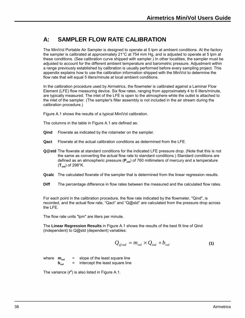
Airmetrics MiniVol Users Guide
38 Airmetrics
Q m Q bstd vol ind vol@ = × + (1)
A: SAMPLER FLOW RATE CALIBRATION
The MiniVol Portable Air Sampler is designed to operate at 5 lpm at ambient conditions. At the factorythe sampler is calibrated at approximately 21°C at 754 mm Hg, and is adjusted to operate at 5 lpm atthese conditions. (See calibration curve shipped with sampler.) In other localities, the sampler must beadjusted to account for the different ambient temperature and barometric pressure. Adjustment withina range previously established by calibration is usually performed before every sampling project. Thisappendix explains how to use the calibration information shipped with the MiniVol to determine theflow rate that will equal 5 liters/minute at local ambient conditions.
In the calibration procedure used by Airmetrics, the flowmeter is calibrated against a Laminar FlowElement (LFE) flow measuring device. Six flow rates, ranging from approximately 4 to 6 liters/minute,are typically measured. The inlet of the LFE is open to the atmosphere while the outlet is attached tothe inlet of the sampler. (The sampler's filter assembly is not included in the air stream during thecalibration procedure.)
Figure A.1 shows the results of a typical MiniVol calibration.
The columns in the table in Figure A.1 are defined as:
Qind Flowrate as indicated by the rotameter on the sampler.
Qact Flowrate at the actual calibration conditions as determined from the LFE.
Q@std The flowrate at standard conditions for the indicated LFE pressure drop. (Note that this is notthe same as converting the actual flow rate to standard conditions.) Standard conditions aredefined as an atmospheric pressure (Pstd) of 760 millimeters of mercury and a temperature(Tstd) of 298°K.
Qcalc The calculated flowrate of the sampler that is determined from the linear regression results.
Diff The percentage difference in flow rates between the measured and the calculated flow rates.
For each point in the calibration procedure, the flow rate indicated by the flowmeter, "Qind", isrecorded, and the actual flow rate, “Qact” and “Q@std” are calculated from the pressure drop acrossthe LFE.
The flow rate units "lpm" are liters per minute.
The Linear Regression Results in Figure A.1 shows the results of the best fit line of Qind(independent) to Q@std (dependent) variables:
where mvol = slope of the least square linebvol = intercept the least square line
The variance (r2) is also listed in Figure A.1.

Appendix A: Calculating Flow Rate
Airmetrics 39
Figure A.1. Portable Sampler Calibration Output

Airmetrics MiniVol Users Guide
40 Airmetrics
P PE
act sea= × −
1
145330
5 25.
(2)
I
P
P
T
Tb
msp
act
std
std
actvol
vol
=× × −50.
(3)
Sampling at Ambient Conditions
The MiniVol's size-selective inlet is an impactor whose particle size selection characteristic isdependent upon the velocity with which the air stream impacts upon the impaction plate. The impactoris designed to have a nominal 10μm (part 206-000) or 2.5μm (part 206-100) cut off at an actual airflow rate of 5.0 liters per minute. To maintain this cut off size, the sampler’s flow rate must be adjusted(flowmeter set point - Isp) so that the flow rate through the size-selective inlet is maintained at 5.0 lpmat ambient conditions.
To calculate the flowmeter set point, you need:
• the sampler’s calibration slope, mvol, and intercept, bvol. This information is supplied to you on the“MiniVol Portable Sampler NIST Traceable Flow Calibration” that came with your sampler (FigureA.1);
• the expected ambient temperature, Tact, in K°, and pressure, Pact, in mm Hg, expected during thesampling study. This data may be estimated from local weather service data or from otherreported historical data. If the U.S Weather Service atmospheric pressure is used, be sure thatthe “station pressure” is used. That is, atmospheric pressure not corrected for the reporting site’selevation above sea level.
If the local “station pressure”, Pact is not readily available, it can be reasonably estimated by usingEquation 2.
Where Pact = ambient atmospheric pressurePsea = sea level atmospheric pressure (nominally 760 mm Hg)E = site elevation in feet
The Flowmeter Set Point, Isp, is calculated using Equation 3.
Where Isp = flowmeter set point, liters/minutePstd = standard atmospheric pressure, 760 mm HgTstd = standard temperature, 298 K°Pact = actual ambient pressure, mm HgTact = actual ambient temperature, K°
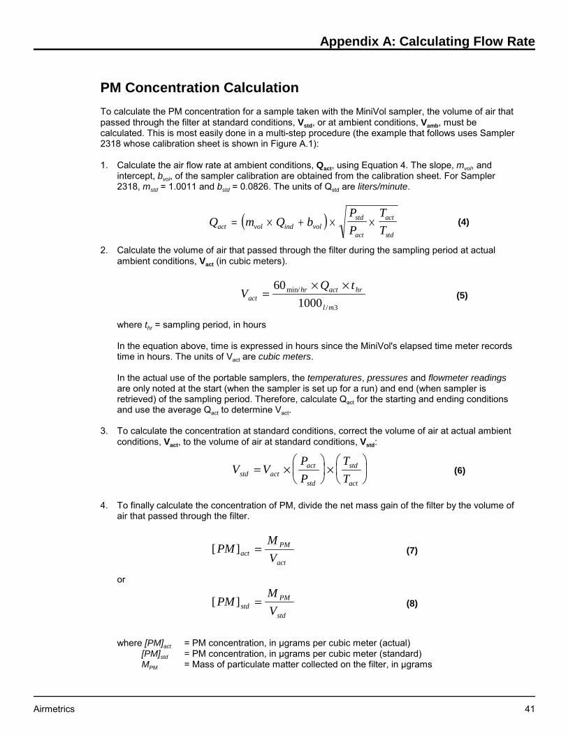
Appendix A: Calculating Flow Rate
Airmetrics 41
( )Q m Q bP
P
T
Tact vol ind volstd
act
act
std
= × + × × (4)
VQ t
acthr act hr
l m
=× ×60
1000 3
min/
/
(5)
V VP
P
T
Tstd actact
std
std
act
= ×
×
(6)
[ ]PMM
VactPM
act
= (7)
[ ]PMM
VstdPM
std
= (8)
PM Concentration Calculation
To calculate the PM concentration for a sample taken with the MiniVol sampler, the volume of air thatpassed through the filter at standard conditions, Vstd, or at ambient conditions, Vamb, must becalculated. This is most easily done in a multi-step procedure (the example that follows uses Sampler2318 whose calibration sheet is shown in Figure A.1):
1. Calculate the air flow rate at ambient conditions, Qact, using Equation 4. The slope, mvol, andintercept, bvol, of the sampler calibration are obtained from the calibration sheet. For Sampler2318, mstd = 1.0011 and bstd = 0.0826. The units of Qstd are liters/minute.
2. Calculate the volume of air that passed through the filter during the sampling period at actualambient conditions, Vact (in cubic meters).
where thr = sampling period, in hours
In the equation above, time is expressed in hours since the MiniVol's elapsed time meter recordstime in hours. The units of Vact are cubic meters.
In the actual use of the portable samplers, the temperatures, pressures and flowmeter readingsare only noted at the start (when the sampler is set up for a run) and end (when sampler isretrieved) of the sampling period. Therefore, calculate Qact for the starting and ending conditionsand use the average Qact to determine Vact.
3. To calculate the concentration at standard conditions, correct the volume of air at actual ambientconditions, Vact, to the volume of air at standard conditions, Vstd:
4. To finally calculate the concentration of PM, divide the net mass gain of the filter by the volume ofair that passed through the filter.
or
where [PM]act = PM concentration, in μgrams per cubic meter (actual) [PM]std = PM concentration, in μgrams per cubic meter (standard) MPM = Mass of particulate matter collected on the filter, in μgrams

Airmetrics MiniVol Users Guide
42 Airmetrics
B: QUICK REFERENCE
Particulate Matter Sampling Routine at Site
Note: Perform as much work as possible inside a vehicle (disassembling sampler, checking for leaks,replacing filter, etc.), particularly if the weather is rainy, windy, or snowy.
1. Hoist the sampler down from the mounting cradle, keeping the hoisting pole as vertical aspossible to avoid dropping the sampler or damaging the preseparator/filter holder assembly withthe hook.
2. Remove the timer and pump assembly by grasping the 6" lid and depressing the snap buttons,taking care not to disconnect power cord from battery. Do NOT grasp center of circuit board.Mount the assembly on the edge of the sampler casing using the pump mount stand. Leave thebattery attached.
3. Record the hours shown on the elapsed time totalizer.
4. Press the Timer On/Auto/Off button to start pump.
Error: If a RED LED is lit (either low flow or low battery), record the error then press the resetbutton to start pump.
5. With the sampler held vertically, read the flowmeter (to the nearest tenth at center of ball) andrecord the ending flow rate.
6. Lower assembly back into tube and secure snap buttons.
7. Before removing the preseparator/filter holder assembly from sampler, cross-check the filtersticker number on the assembly against the filter number for that site on the worksheet. Thesenumbers should match. If not, make a note of this, recording the actual filter number.
8. Remove the preseparator/filter holder assembly at the quick-connect and place it in clean plasticbag for transport back to lab.
9. Change the battery pack. (Do not inadvertently confuse and reuse the spent battery.) If either thelow flow or low voltage indicator was lit, make a note that the spent battery may be defective.
10. Check the sampler for leaks. Remove the pump and timer assembly from the sampler body, startthe pump by pressing the On/AUTO/Off button, and cover the inlet with palm. The ball shoulddrop to the bottom of the flowmeter. If it does not, check/tighten all tubing, joints, and quick-connect fittings until the sampler is leak-free.
11. Attach a new preseparator/filter holder assembly containing a new filter at the sampler quick-connect.
12. If the low flow indicator was lit, check for crimps or air restrictions in the inlet or tubing.
13. On a new Field Data Log worksheet, record site #, sampler #, battery #, and new filter #.
14. With the sampler running and while holding it vertically, adjust the flow rate to the correct level.Record the beginning flow rate to the nearest tenth of liter/minute.
15. Turn the pump off by pressing ON/AUTO/OFF button.
Appendix B: Quick Reference
Airmetrics 43
16. Record hours shown on the Elapsed Time Totalizer.
17. Program the Programmable Timer.
18. Lower the pump and timer assembly into the sampler body and secure snap buttons.
19. Return the sampler to the mounting cradle, raising it as vertically as possible.
20. If also doing gas sampling, see the following Integrated Gas Sampling Routine.
Integrated Gas Sampling Routine At Site
Note: Perform as much work as possible inside a vehicle (disassembling sampler, replacingcanisters, etc.), particularly if the weather is rainy, windy, or snowy.
1. Lower sampler from its cradle mount, keeping the hoisting pole as vertical as possible to avoiddropping the sampler or damaging the preseparator/filter assembly with hook.
2. Remove the bale bar handle assembly. Detach canister tubing at the mini quick-connect fittingsand remove canisters.
3. Depress the snap buttons and remove the pump and timer assembly, taking care not to pull theconnecting wire loose. Hold the top cap. Do NOT grasp the circuit board. Mount the assembly onthe sampler casing using the triangular mount stand.
4. Verify correct time and day of week on time LCD.
5. Record elapsed time as shown on the Elapsed Time Totalizer, which should match theprogrammed time.
6. Check and record the fullness of the bag(s), adjusting the pulse interval or duration if necessary.
7. Program the timer for new sampling period (see page 5).
8. Set to "Auto" mode.
9. Change battery pack (see page 15).
IMPORTANT NOTE: The Valve Driver Board automatically resets when the sampler's mainpower is interrupted. This is why the battery must be changed before setting the sequencingcircuit.
10. Check the Active Solenoid Output Indicators. Use the Manual Sequence Advance Button to selectthe required channel if necessary.
11. Lower the pump and timer assembly into the sampler body.
12. Replace the bale bar handle assembly, attach new canisters, and connect tubing.
13. Return the sampler to the mounting cradle, raising it as vertically as possible.
14. If also doing particulate matter sampling, see the preceding Particulate Matter Sampling Routine.

Airmetrics MiniVol Users Guide
44 Airmetrics
C: WARRANTY POLICY
What is Covered
The MiniVol Portable Air Sampler is warranted by Airmetrics against defects in materials andworkmanship for one year from the date of original purchase. If you sell your unit or give it as a gift,the warranty is automatically transferred to the new owner and remains in effect for the original one-year period. During the warranty period, we will repair or, at our option, replace at no charge a samplerthat proves to be defective, provided you return the sampler, shipping prepaid, to Airmetrics.(Replacement may be with a newer model of equivalent or better functionality.)
This warranty gives you specific legal rights, and you may also have other rights that vary from state tostate, province to province, or country to country.
What is Not Covered
AA batteries, and damages caused by AA batteries, are not covered by the Airmetrics warranty.
This warranty does not apply if the product has been damaged by accident or misuse or as the resultof service or modification by other than an Airmetrics technician.
No other express warranty is given. The repair or replacement of a product is your exclusive remedy.Any other implied warranty of merchantability or fitness is limited to the one-year duration of thiswritten warranty.
Some states, provinces, or countries do not allow limitations on how long an implied warranty lasts, sothe above limitation may not apply to you. In no event shall Airmetrics be liable for consequentialdamages. Some states, provinces, or countries do not allow the exclusion of limitation of incidental orconsequential damages, so the above limitation or exclusion may not apply to you.
Warranty on Service
Service is warranted against defects in materials and workmanship for 90 days from the date ofservice.
Service Agreements
In the US., a support agreement is available for repair and service. For additional information, contact:
Airmetrics2095 Garden Ave.
Suite 102Eugene, OR 97403
U.S.A.(541) 683-5420

Appendix D: Parts List
Airmetrics 45
REPLACING DAMAGED / DEFECTIVE COMPONENTS
In the event that a MiniVol Portable Air Sampler component is missing, damaged, or defective, followthese steps to obtain a replacement part:
! Call or email Airmetrics tech support and explain the problem.
! Obtain authorization to return the defective or damaged components.
! Package the item(s) carefully to prevent further damage.
! Identify the item(s) being returned on a clearly marked packing list with your name, companyname, address, and phone number.
! Ship to our shop address:
Airmetrics2095 Garden Ave.
Suite 102Eugene, OR 97403
U.S.A.(541) 683-5420
! Items will be repaired/replaced and returned as soon as possible.

Airmetrics MiniVol Users Guide
46 Airmetrics
Figure F.1. Main Circuit Board Parts Identification.
D: PARTS LIST
The following Figures and Tables identify the components and parts of the MiniVol sampler.
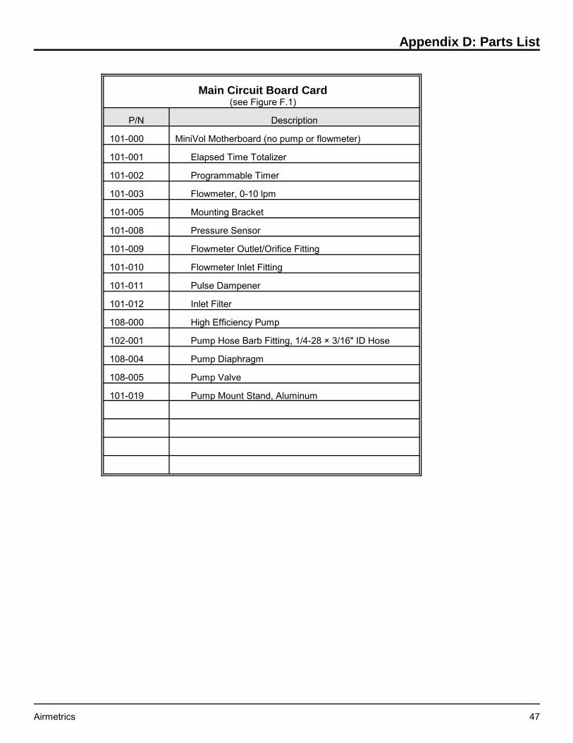
Appendix D: Parts List
Airmetrics 47
Main Circuit Board Card(see Figure F.1)
P/N Description
101-000 MiniVol Motherboard (no pump or flowmeter)
101-001 Elapsed Time Totalizer
101-002 Programmable Timer
101-003 Flowmeter, 0-10 lpm
101-005 Mounting Bracket
101-008 Pressure Sensor
101-009 Flowmeter Outlet/Orifice Fitting
101-010 Flowmeter Inlet Fitting
101-011 Pulse Dampener
101-012 Inlet Filter
108-000 High Efficiency Pump
102-001 Pump Hose Barb Fitting, 1/4-28 × 3/16" ID Hose
108-004 Pump Diaphragm
108-005 Pump Valve
101-019 Pump Mount Stand, Aluminum

Airmetrics MiniVol Users Guide
48 Airmetrics
Figure F.2. Valve Driver Board Parts Identification
Valve Driver Board(see Figure F.2)
P/N Description
103-000 Complete Valve Driver Board
103-001 Valve Driver Circuit Board
103-007 Pnuetronics Solenoid Valves Assy.
104-001 Panel Mount Mini Quick Connect, male
104-011 Female Mini Quick Connect

Appendix D: Parts List
Airmetrics 49
Figure F.4. Preseparator and Filter Parts Identification
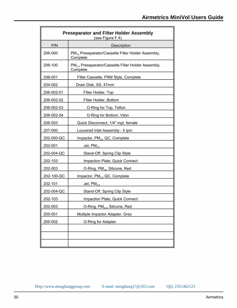
Airmetrics MiniVol Users Guide
50 Airmetrics
Preseparator and Filter Holder Assembly(see Figure F.4)
P/N Description
206-000 PM10 Preseparator/Cassette Filter Holder Assembly,Complete
206-100 PM2.5 Preseparator/Cassette Filter Holder Assembly,Complete
206-001 Filter Cassette, FRM Style, Complete
204-002 Drain Disk, SS, 47mm
206-002-01 Filter Holder, Top
206-002-02 Filter Holder, Bottom
206-002-03 O-Ring for Top, Teflon
206-002-04 O-Ring for Bottom, Viton
206-003 Quick Disconnect, 1/4" mpt, female
207-000 Louvered Inlet Assembly - 5 lpm
202-000-QC Impactor, PM10, QC, Complete
202-001 Jet, PM10
202-004-QC Stand-Off, Spring Clip Style
202-103 Impaction Plate, Quick Connect
202-003 O-Ring, PM10, Silicone, Red
202-100-QC Impactor, PM2.5 QC, Complete
202-101 Jet, PM2.5
202-004-QC Stand-Off, Spring Clip Style
202-103 Impaction Plate, Quick Connect
202-003 O-Ring, PM2.5, Silicone, Red
205-001 Multiple Impactor Adapter, Grey
205-002 O-Ring for Adapter
Http://www.menglianggroup.com E-mail: [email protected] QQ: 2351462123

Appendix D: Parts List
Airmetrics 51
Figure F.5. Battery Pack Parts Identification

Airmetrics MiniVol Users Guide
52 Airmetrics
Battery Pack Assembly(see Figure F.5)
P/N Description
300-100 Battery Pack Assembly
302-000 Battery, 12V, 12AH
303-000 Mounting Catch
304-000R Banana Jack, Red
304-000B Banana Jack, Black
301-000A Battery Charger, 12vdc
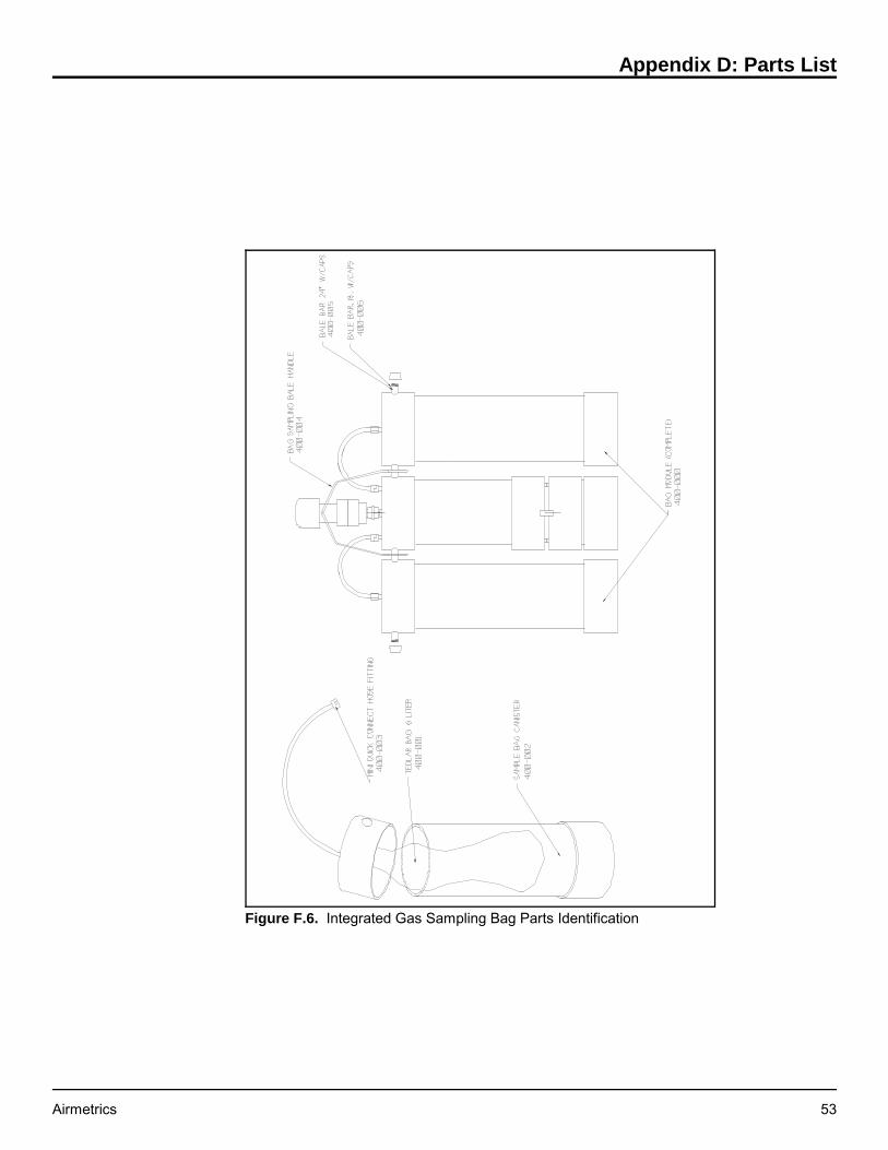
Appendix D: Parts List
Airmetrics 53
Figure F.6. Integrated Gas Sampling Bag Parts Identification

Airmetrics MiniVol Users Guide
54 Airmetrics
Integrated Gas Sampling Bag Assembly(see Figure F.6)
P/N Description
400-000 Complete Bag Module
400-001 Tedlar® Bag, 5 liter
400-003 Mini Quick-Connect Hose Fitting
107-000 Bag Sampling Bale Handle
400-005 Bale Bar, 24", PVC
400-010 Bag evacuation Fitting
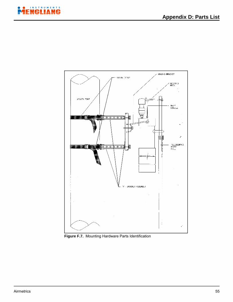
Appendix D: Parts List
Airmetrics 55
Figure F.7. Mounting Hardware Parts Identification

Airmetrics MiniVol Users Guide
56 Airmetrics
Mounting Hardware(See Figure F.7)
P/N Description
501-000 Complete Telescoping Hoisting Pole Assembly
501-001 Telescoping Fiberglass Pole
501-002 Pole Hook
502-000 Mounting Cradle
504-000 Y-Bracket Assembly (Complete)
600-001 Operating Manual

Appendix D: Parts List
Airmetrics 57
Sampler Case External Hardware/Power Interconnect
P/N Description
104-003 Male Quick Connect Inlet Fitting
104-004 Battery Pack Mounting Latch
104-005 Banana Plug
105-000 Interconnect Board
105-002 Power Cable
107-000 Bale Handle, Complete

Airmetrics MiniVol Users Guide
58 Airmetrics
Figure F.8 Louvered Inlet Assembly
Http://www.menglianggroup.com E-mail: [email protected] QQ: 2351462123

Appendix D: Parts List
Airmetrics 59
Louvered Inlet Assembly(See Figure F.8)
KEY P/N Description
207-000 Louvered Inlet Assembly
1 207-001 Body
2 207-002 Shield - Lower
3 207-003 Shield - Upper
4 207-004 Bug Screen
5 207-005 Deflector Cone
6 207-006 O-Ring
7 207-007 Stand Off
8 301-005 Machine Screw
Http://www.menglianggroup.com E-mail: [email protected] QQ: 2351462123