operation and service manual for hermetic sampler … and service manual for hermetic sampler a.2...
TRANSCRIPT

50403/SA2/0912 HERMetic Sampler A2 1
Operation and Service Manual
for HERMetic Sampler A.2 0.5 liter
Portable Restricted Sampling Device
Note: before using the instrument please read this book.
This document is subject to changes without notice.
50403/SA2/0912 HERMetic Sampler A2 2
1. Table of contents
1. TABLE OF CONTENTS 2
2. RECOMMENDATION FOR SAFE USE 3
3. GENERAL INFORMATION 4 3.1 SHIPMENT NOTE 4 3.2 INITIAL INSPECTION 4 3.3 DOCUMENTATION DISCREPANCIES 4 3.4 WARRANTY 4 3.5 CERTIFICATION 5 3.6 SPARE PARTS 5 3.7 SERVICE AND REPAIR 5
4. WORLDWIDE SERVICE STATIONS NETWORK 7
5. DESCRIPTION 9 5.1 GENERAL 9 5.2 SAMPLING TYPES 9 5.3 SAMPLING PRINCIPLE 10
5.3.1 CONNECTION AND GROUNDING SYSTEM 10 5.3.2 SAMPLING METHOD 11 5.3.3 LIQUID TRANSFER 11
6. OPERATION 12 6.1 CHECKING BEFORE USE 12 6.2 OPERATING THE ZONE SAMPLING BOTTLE 13 6.3 OPERATING THE BOTTOM SAMPLING BOTTLE 14 6.4 OPERATING THE SPOT SAMPLING BOTTLE 15 6.5 OPERATING THE RUNNING SAMPLING BOTTLE 16
7. CARE & MAINTENANCE 17 7.1 SAFETY WARNING 17 7.2 CARE 17 7.3 SAMPLER CLEANING 17 7.4 TAPE CLEANING 18 7.5 TAPE WIPER REPLACEMENT 18 7.6 TAPE REPLACEMENT 18
8. SPECIFICATIONS 19
9. DRAWINGS 20 9.1 SAMPLER 20 9.2 VALVES 20

50403/SA2/0912 HERMetic Sampler A2 3
2. Recommendation for safe use
1. This Operation and Service Manual is a guide in order to help the user to operate the instrument to our
best knowledge. 2. Nevertheless the maker disclaims all responsibility and liability for damage resulting from the use of the
equipment regardless of the cause of the damage. 3. Attention is drawn to the possible hazard due to electrostatic charges which may be present in
the tank. This may happen in particular with static accumulator liquids, i.e. liquids which have low conductivity of 50 picoSiemens/metre (pS/m) or less.
4. It is very important that the instrument is grounded to the tank before the probe is introduced into
the tank and remains grounded until after complete withdrawal from the tank.
4.1. If the instrument is installed with the quick connect coupler, grounding is effected through the quick connect coupler and the mating nipple of the valve provided that these parts are kept clean and free from corrosion in order to guarantee electrical conductivity. If a grease is used for this purpose, it must be one which contains graphite.
4.2. If the instrument is not connected to the mating deck valve, the instrument has to be also earthed
by means of the grounding cable and clamp. 5. It is anticipated that the user will have specific operating methods laid down to ensure safety
when using this type of apparatus. In this case the user's instructions shall be strictly observed. 6. In the absence of such instructions the following should be noted:
6.1. If a metal sounding pipe is fitted beneath the deck valve or tank is inerted, then ullaging, etc. is permissible at any time with no restriction.
6.2. If there is no sounding tube or tank is not inerted, the following precautions shall be taken:
6.2.1. If the cargo is not a static accumulator liquid, i.e. its conductivity is more than 50 pS/m, then ullaging is permitted provided that the instrument is properly grounded and earthed before the probe is inserted into the tank and remains earthed until the probe has been removed from the tank.
6.2.2. If the cargo is a static accumulator liquid, i.e. its conductivity is less than 50 pS/m, then
ullaging is permitted provided that:
6.2.2.1. The instrument is properly grounded and earthed before the probe is inserted into the tank and remains earthed until the probe has been removed from the tank.
6.2.2.2. The apparatus is not introduced into a tank until at least 30 minutes have elapsed after completion of any loading operation or stopping the injection of inert gas.
6.3. For further guidance refer to International Safety Guide for Oil Tankers and Terminals (ISGOTT),
ISBN 1-85609-291-7, Fifth Edition 2006, or consult the appropriate Legislative Authority for the installation.
7. This product and his use is / may be related to international, national, local or company
regulations or standards. It is the customer / user responsibility to ensure that the way to use the device complies with such applicable regulations or standards.
8. This device is a protable product. It must not be permanently installed on the tank and must be
disconnected after use and stored in a safe and dry area.

50403/SA2/0912 HERMetic Sampler A2 4
3. General information
3.1 Shipment note
The following parts should be included in the shipment: - 1 instrument; - One or more bottles as ordered; - 1 Allen key 5mm - 1 Operation and Service Manual.
3.2 Initial inspection
Check the contents of the shipment for completeness and note whether any damage has occurred during transport. Carry out the “Initial test before installing the instrument” to verify the good functioning. If the contents are incomplete, or if there is damage, not use the device. A claim should be filled with the carrier immediately, and Enraf Tanksystem SA Sales or Service organization should be notified in order to facilitate the repair or replacement of the instrument.
3.3 Documentation discrepancies
The design of the instrument is subject to continuous development and improvement. Consequently, the instrument may incorporate minor changes in detail from the information contained in the manual.
3.4 Warranty
12 months after installation but max. 18 months after delivery ex works. The Vendor undertakes to remedy any defect resulting from faulty design materials or workmanship. The Vendor's obligation is limited to the repair or replacement of such defective parts by his own plant or one of his authorized service stations. The Purchaser shall bear the cost and risk of transportation of defective parts and repaired parts supplied in replacement of such defective parts.
When returned to Enraf Tanksystem SA or any of its agreed Service Stations equipment must be contamination-free. If it is determined that the Purchasers equipment is contaminated, it will be returned to the Purchaser at the Purchasers expense. Contaminated equipment will not be repaired, replaced, or covered under any warranty until such time that the said equipment is decontaminated by the Purchaser. The Purchaser shall notify by fax, telex or in writing of any defect immediately upon discovery, specifying the nature of the defect and/or the extend of the damage caused thereby. Where no other conditions have been negotiated between the Vendor and the Purchaser "General Conditions 188" of United Nations shall apply. This equipment has been certified as non-electrical equipment for potentially explosive atmospheres for only those classes or categories of hazardous areas stated on the instrument label, bearing the mark of the applicable approval authority. No other usage is authorized. Unauthorized repair or component replacement by non original spare parts by the Purchaser will void this guarantee and may impair the good functioning of the instrument. In no event shall Enraf Tanksystem SA be liable for indirect, incidental or consequential loss or damage or failure of any kind connected with the use if its products or failure of its products to function or operate properly. Enraf Tanksystem SA do not assume the indemnification for any accident or damage caused by the operation of its product and the warranty is limited to the replacement of parts or complete goods.
50403/SA2/0912 HERMetic Sampler A2 5
3.5 Certification
3.6 Spare parts
Substitution of components may impact safety. Use only original spare parts. When ordering spares identify the spare part by TS number and description. Refer to section “Drawings”. Some spares might be repairable; in this case send part to any authorized service center or to the factory. In case of urgency replacement units can be available while stocks last.
3.7 Service and Repair
The customer should take care of the freight and customs clearance charges. If units are sent on "freight collect» the charges will be invoiced to the customer. When returning units or parts for repair to the factory please fill out a service request form (see next page). When returned to Enraf Tanksystem SA equipment must be contamination-free. If it is determined that the customers equipment is contaminated, it will be returned to the customer at the customers expense. Contaminated equipment will not be repaired until such time that the customer decontaminates the said equipment.
Enraf Tanksystem SA is an ISO 9001 certified company by QMI and MED-D by Det Norske
Veritas Certification GmbH.

50403/SA2/0912 HERMetic Sampler A2 6
Service Request
Customer's address: .............................................................................. ................................................................................................................ ................................................................................................................ ................................................................................................................ ................................................................................................................ ................................................................................................................
Telephone: ..............................................................................................
Telex: .......................................................................................................
Fax: .........................................................................................................
Type of unit or part: ................................................................................. .................................................................................................................
Serial number: .........................................................................................
Short description of defective unit or part: ............................................... .................................................................................................................. .................................................................................................................. .................................................................................................................. .................................................................................................................. .................................................................................................................. .................................................................................................................. ..................................................................................................................
Do you want a quotation before repair is started:..........yes / no.............
Repaired unit has to be returned to the following address: .................................................................................................................. .................................................................................................................. .................................................................................................................. .................................................................................................................. .................................................................................................................. .................................................................................................................. ..................................................................................................................

50403/SA2/0912 7 HERMetic Sampler A2
4. Worldwide Service Stations network
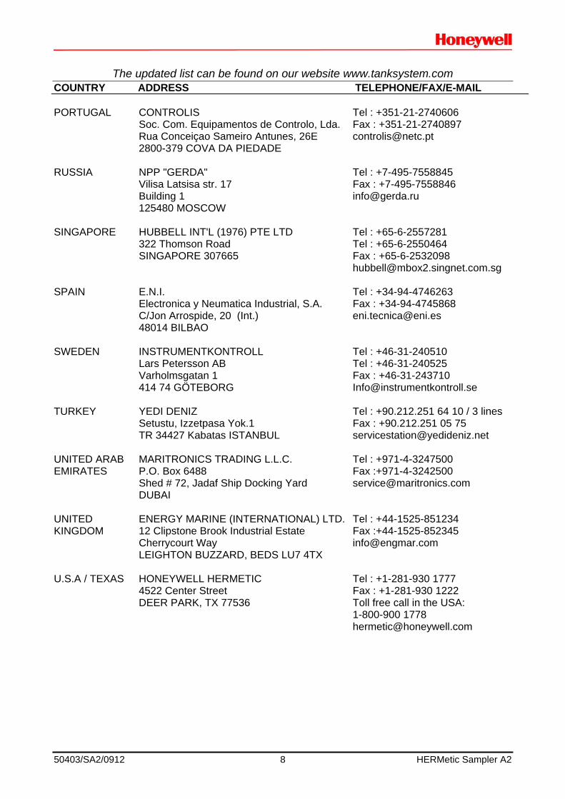
The updated list can be found on our website www.tanksystem.com
COUNTRY ADDRESS TELEPHONE/FAX/E-MAIL SWITZERLAND ENRAF TANKSYSTEM SA
2, rue de l'Industrie CH-1630 BULLE
Tel : +41-26-91 91 500 Fax : +41-26-91 91 505 [email protected]
CANADA PYLON ATLANTIC
A Div. Of Pylon Electronics Inc. 31 Trider Crescent., DARTMOUTH, N.S. B3B 1V6
Tel : +1-902-4683344 Fax : +1-902-4681203 [email protected]
CHINA HUA HAI EQUIPMENT & ENGINEERING
CO LTD Factory 7, Lane 1365, East Kang Qiao Road Kang Qiao Industrial Zone, Pu Dong SHANGHAI, P.C. 201315
Tel : +86-21-68183183 Fax : +86-21-68183115 [email protected]
GREECE SPANMARIN
86, Filonos Street GR-185 36 PIRAEUS
Tel : +30-210-4294498 Fax : +30-210-4294495 [email protected]
JAPAN DAIWA HANBAI CORPORATION LTD
2-10-31, Mitejima, Nishiyodogawa-ku OSAKA 555-0012
Tel : +81-6-64714701 Fax : +81-6-64729008 [email protected]
KOREA World Ocean CO., LTD
Rm1001, Hae-deok Bldg., 1212-11 Choryang-dong Dong-Gu BUSAN
Tel : +82-51-462-2554/5 Fax : +82-51-462-0468 [email protected]
MEXICO URBAN DEL GOLFO S.A. DE C.V.
Ave. Ejército Mexicano 1902 Col. Loma del Gallo 89460 CD. MADERO, TAMPS. MEXICO
Tel : +52-833-2170190 Fax : +52-833-2170190 [email protected]
NETHERLANDS B.V. TECHNISCH BUREAU
UITTENBOGAART Brugwachter 13 NL-3034 KD ROTTERDAM
Tel : +31-10-4114614 Fax : +31-10-4141004 [email protected]
50403/SA2/0912 8 HERMetic Sampler A2
The updated list can be found on our website www.tanksystem.com COUNTRY ADDRESS TELEPHONE/FAX/E-MAIL PORTUGAL CONTROLIS
Soc. Com. Equipamentos de Controlo, Lda. Rua Conceiçao Sameiro Antunes, 26E 2800-379 COVA DA PIEDADE
Tel : +351-21-2740606 Fax : +351-21-2740897 [email protected]
RUSSIA NPP "GERDA"
Vilisa Latsisa str. 17 Building 1 125480 MOSCOW
Tel : +7-495-7558845 Fax : +7-495-7558846 [email protected]
SINGAPORE HUBBELL INT'L (1976) PTE LTD
322 Thomson Road SINGAPORE 307665
Tel : +65-6-2557281 Tel : +65-6-2550464 Fax : +65-6-2532098 [email protected]
SPAIN E.N.I.
Electronica y Neumatica Industrial, S.A. C/Jon Arrospide, 20 (Int.) 48014 BILBAO
Tel : +34-94-4746263 Fax : +34-94-4745868 [email protected]
SWEDEN INSTRUMENTKONTROLL
Lars Petersson AB Varholmsgatan 1 414 74 GÖTEBORG
Tel : +46-31-240510 Tel : +46-31-240525 Fax : +46-31-243710 [email protected]
TURKEY YEDI DENIZ
Setustu, Izzetpasa Yok.1 TR 34427 Kabatas ISTANBUL
Tel : +90.212.251 64 10 / 3 lines Fax : +90.212.251 05 75 [email protected]
UNITED ARAB EMIRATES
MARITRONICS TRADING L.L.C. P.O. Box 6488 Shed # 72, Jadaf Ship Docking Yard DUBAI
Tel : +971-4-3247500 Fax :+971-4-3242500 [email protected]
UNITED KINGDOM
ENERGY MARINE (INTERNATIONAL) LTD.12 Clipstone Brook Industrial Estate Cherrycourt Way LEIGHTON BUZZARD, BEDS LU7 4TX
Tel : +44-1525-851234 Fax :+44-1525-852345 [email protected]
U.S.A / TEXAS HONEYWELL HERMETIC
4522 Center Street DEER PARK, TX 77536
Tel : +1-281-930 1777 Fax : +1-281-930 1222 Toll free call in the USA: 1-800-900 1778 [email protected]
50403/SA2/0912 9 HERMetic Sampler A2
5. Description
5.1 General
The HERMetic Samplers are designed for sampling of liquids or chemicals, which present a Fire-, Health- or Air pollution Hazard. The equipment is designed for use in potentially explosive atmospheres area.
5.2 Sampling types
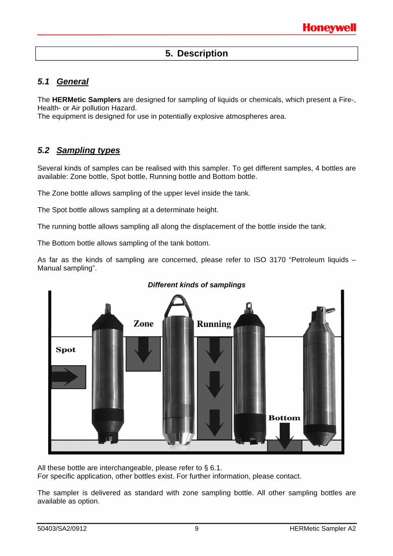
Several kinds of samples can be realised with this sampler. To get different samples, 4 bottles are available: Zone bottle, Spot bottle, Running bottle and Bottom bottle. The Zone bottle allows sampling of the upper level inside the tank. The Spot bottle allows sampling at a determinate height. The running bottle allows sampling all along the displacement of the bottle inside the tank. The Bottom bottle allows sampling of the tank bottom. As far as the kinds of sampling are concerned, please refer to ISO 3170 “Petroleum liquids – Manual sampling”.
Different kinds of samplings
All these bottle are interchangeable, please refer to § 6.1. For specific application, other bottles exist. For further information, please contact. The sampler is delivered as standard with zone sampling bottle. All other sampling bottles are available as option.
50403/SA2/0912 10 HERMetic Sampler A2
5.3 Sampling principle
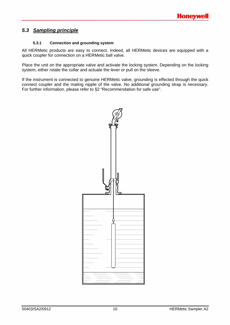
5.3.1 Connection and grounding system
All HERMetic products are easy to connect. Indeed, all HERMetic devices are equipped with a quick coupler for connection on a HERMetic ball valve. Place the unit on the appropriate valve and activate the locking system. Depending on the locking system, either rotate the collar and actuate the lever or pull on the sleeve. If the instrument is connected to genuine HERMetic valve, grounding is effected through the quick connect coupler and the mating nipple of the valve. No additional grounding strap is necessary. For further information, please refer to §2 “Recommendation for safe use”.

50403/SA2/0912 11 HERMetic Sampler A2
5.3.2 Sampling method
The sample is taken by a vertical move of the bottle inside the fluid. The bottle is linked with a graduated tape to monitor the bottle location. For complete explanation of sampling procedures, please refer to §6 “Operation”. Important note: to avoid contamination of the sample taken by the sampler itself, check and clean the unit and the bottle prior to use. Clean the unit with an appropriate cleaner without impacting the unit or contamination risk of the next sample.
5.3.3 Liquid transfer
To transfer the fluid, no additional equipment is necessary. Just remove the sampling bottle through bottom of Sampler and pour its content into an appropriated laboratory bottle.

50403/SA2/0912 12 HERMetic Sampler A2
6. Operation
6.1 Checking before use
Before using the sampler:
Check the good state of the device.
Check the cleanliness of the unit (sampler and bottle) to prevent any contamination of the sample.
Inspect the bottle tape end for breaks, kinks and wear. If there is some damage, replace
the tape before use. Check of the attachment of the hook locking device on the tape.
Check the closure of the hook locking device according to Fig. 1. The swivel hook has to be
locked in use. Nota: Clean the instrument of any excess of liquid after use. Remove the winder holder and clean the storage tube. This cleaning must be done very properly, in particular when corrosive liquids are gauged, such as strong acids or caustic soda for instance. Store the instrument in a dry location.
Tape inspection
Fig. 1
Hook Locked Hook Unlocked

50403/SA2/0912 13 HERMetic Sampler A2
6.2 Operating the ZONE SAMPLING BOTTLE
ND TS DESCRIPTION
30329 10380 Zone Bottle 0,43 l. Viton assy
1. Remove the 2” cover from the valve. 2. Install the sampler on top of the valve. 3. Open the valve. 4. Lower the bottle at a minimum speed of 0,5 m/sec. If the lowering speed is too low the liquid will not flow through the bottle. The resistance of
the ball to flowing has to be higher than its weight to keep open the bottom valve of the bottle.
5. Stop the lowering at the level where the sample is to be taken. 6. Lift the bottle back into the sampler housing. 7. Close the valve. 8. Remove the cover of the sampler together with the bottle and pour its content into a
laboratory bottle with a minimum 2” neck diameter. 9. Reassemble the bottle and cover to the sampler. 10. Remove the sampler from the valve. 11. Reinstall the 2” cover on top of the valve. 12. Clean the equipment after use and check it for proper functioning.

50403/SA2/0912 14 HERMetic Sampler A2
6.3 Operating the BOTTOM SAMPLING BOTTLE
(O = OPTION)
ND TS DESCRIPTION
O 20246 20124 Bottom bottle 0.40 l FKM assy
1. Remove the 2” cover from the valve. 2. Install the sampler on top of the valve. 3. Open the valve. 4. Lower the bottom bottle until reaching the bottom of the tank. 5. When the bottom valve of the bottle hits the tank bottom the bottle fills up automatically. 6. Lift the bottle back into the sampler. 7. Close the valve. 8. Remove the cover of the sampler together with the bottom bottle. Mind not to open the
bottom valve inadvertently. 9. Put the bottom bottle vertically into a laboratory bottle with a minimum 2” neck diameter. 10. When the bottle bottom valve hits the bottom of the laboratory bottle the liquid is transferred. 11. Reassemble the bottom bottle and the cover to the sampler. 12. Remove the sampler from the valve. 13. Reinstall the 2” cover on top of the valve. 14. Clean the equipment after use and check it for proper functioning.

50403/SA2/0912 15 HERMetic Sampler A2
6.4 Operating the SPOT SAMPLING BOTTLE
(O = OPTION)
ND TS DESCRIPTION
O 20255 20137 Spot bottle 0.40 l. FKM
1. Remove the 2” cover from the valve. 2. Install the sampler on top of the valve. 3. Open the valve. 4. Lower the spot bottle to the level where the sample is to be taken.
5. Stop the bottle at this level and shake it rapidly up and down about 10 times on a 200 mm
stroke. This movement has a pumping effect as the ball opens and closes the bottom of bottle. 6. Lift the bottle back into the sampler. 7. Close the valve. 8. Remove the cover of the sampler together with the spot bottle. Mind not to open the bottom
valve inadvertently. 9. Put the spot bottle vertically into a laboratory bottle with a minimum 2” neck diameter. 10. When the bottle spot cover hits the bottom of the laboratory bottle the liquid is transferred. 11. Reassemble the spot bottle and the cover to the sampler. 12. Remove the sampler from the valve. 13. Reinstall the 2” cover on top of the valve. 14. Clean the equipment after use and check it for proper functioning.

50403/SA2/0912 16 HERMetic Sampler A2
6.5 Operating the RUNNING SAMPLING BOTTLE
(O = OPTION)
ND TS DESCRIPTION
O 20254 20138 Running bottle 0.40 l. FKM
0. The calibration plug on top of the running bottle has to be adjusted according to the liquid to be sampled. The plug is properly set up when the transferred quantity of liquid falls between 70 and 85% of the capacity of the sampling bottle, i.e. between 0.3 and 0.35 l (API MPMS Chapter 8.1, § 8.3.3.3).
1. Remove the 2” cover from the valve. 2. Install the sampler on top of the valve. 3. Open the valve. 4. Lower the running bottle regularly to the appropriate depth but do not hit the tank bottom to
keep the bottom plug closed all the time. 5. When the appropriate depth has been reached lift the running bottle back into the sampler at
the same regular speed. 6. Close the valve. 7. Remove the cover of sampler together with the running bottle. Mind not to open the bottom
valve inadvertently. 8. Put the running bottle vertically into a laboratory bottle that shall have a 2” minimum neck
diameter. 9. Open the bottom valve by hitting the bottom of the laboratory bottle. Transfer the liquid. 10 When the transfer is completed, check that the transferred liquid falls between the two marks
0.3 and 0.35 l in order to comply with API MPMS Chapter 8.1 requirements. 11. Reassemble the running bottle and the cover to the sampler. 12. Remove the sampler from the valve. 13. Reinstall the 2” cover on top of the valve. 14. Clean the equipment after use and check it for proper functioning.

50403/SA2/0912 17 HERMetic Sampler A2
7. Care & Maintenance
7.1 Safety warning
As this equipment has been designed as non-electrical equipment for potentially explosive atmospheres. Specific precautions have to be taken regarding maintenance of the device. The user can exchange parts and modules if following points are observed: 1. Never carry out any repair or trouble shooting in a hazardous area. 2. Substitution of components may impact safety. Use only original spare parts. 3. Work shall be done only by maintenance personnel who has experience with equipment
certified for use in potentially explosive atmosphere. The design of the equipment is modular, i.e. in case of damage, check which modules or spare parts have to be replaced. Order new parts according to enclosed drawings and specific item number TS -----. The instrument consists of the following modules:
Mechanical parts Tape assembly Tape cleaner
7.2 Care
Clean the instrument of any excess of liquid after use. Remove the winder holder and clean the storage tube. This cleaning must be done very properly, in particular when corrosive liquids are sampled, such as strong acids or caustic soda for instance. Store the instrument in a dry location. Check periodically whether the general state of the device is still OK. Check periodically whether all sealings are still OK. Check the tape wiper for wear. Clean periodically the sampling bottle. Check the valves of sampling bottles for liquid leakage. Check periodically tape for kinks. Check periodically (at least every 6 months) the continuity of grounding by measuring the electrical resistance between the hook lock (or the sampling bottle) and the quick connect coupler. Resistance should not exceed 100 .
7.3 Sampler cleaning
To clean HERMetic Sampler A2, winder holder can be easily removed and sampling bottle detached from tape.

50403/SA2/0912 18 HERMetic Sampler A2
It is required to fit the cleanliness level with the sample goals. Where appropriate, dismantle the winder holder and clean the parts with an appropriate cleaner to prevent any contamination of the sample by the sampler itself.
7.4 Tape cleaning
If tape requires cleaning it has to be unwound. Clean it during its winding-up operation on the winder.
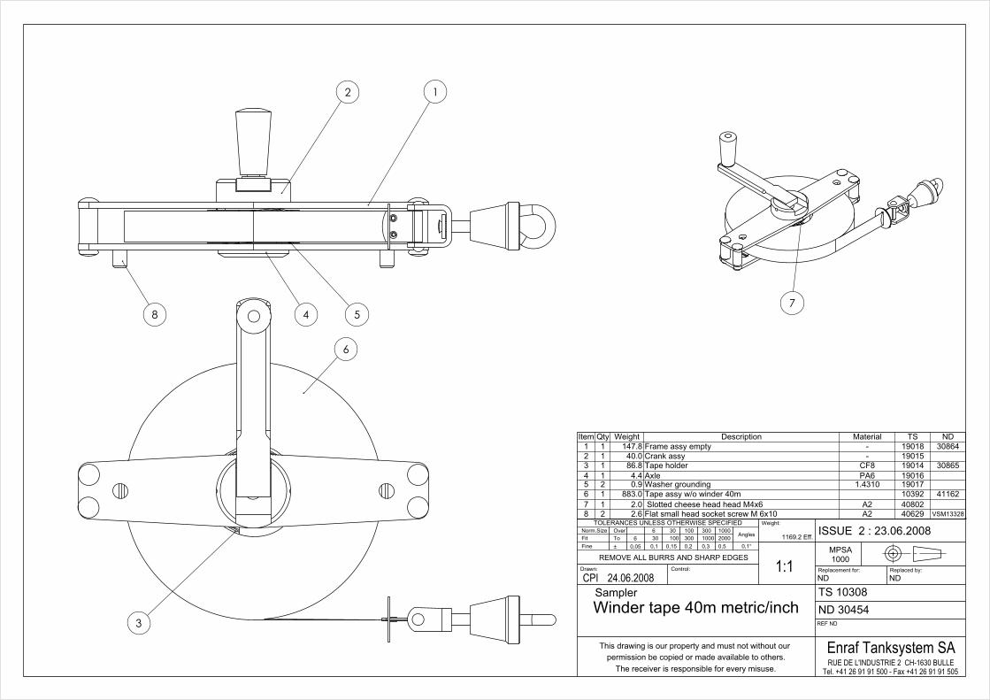
7.5 Tape wiper replacement
Unscrew the 4 screws position 7 on the drawing ND 20319 (30m) or ND 40796 (40m) Remove the old tape wiper. Put the new one. Tighten the 4 screws again.
7.6 Tape replacement
Remove the winder holder from the sampler (2 screws); Remove the tape wiper; Unwind totally the old tape; Remove it and unscrew the screw tightening to the core; Put the new tape; Fasten the tape to the core with the screw; Wind the new tape; Put back the tape wiper. Put back the winder holder and tighten the 2 screws.

50403/SA2/0912 19 HERMetic Sampler A2
8. Specifications
General Specifications Tape length up to 40 m/130 ft approx. Tape graduation Metric/English Tape resolution 1 mm / 1/16” Tape accuracy ±6.3mm/40 m (±1/4”/130 ft approx.) Liquid density up to 8kg/dm³ Ambient temperature range -20°C to 80 °C (-4°F to 176°F) Maximum liquid temperature 80°C (176°F) Mechanical coupling Q2 (2”) Weight 6.2 kg approx. Dimensions 830 x 170 x 140 mm approx Meets ISO 3170 “Petroleum liquids – Manual sampling” Tape cleaning device Adjustable tape cleaner Available bottles Zone, bottom, spot, running sampling bottles Maintenance modular design / easy exchange of parts Specifications subject to change without notice.

50403/SA2/0912 20 HERMetic Sampler A2
9. Drawings
These documents are enclosed in following pages.
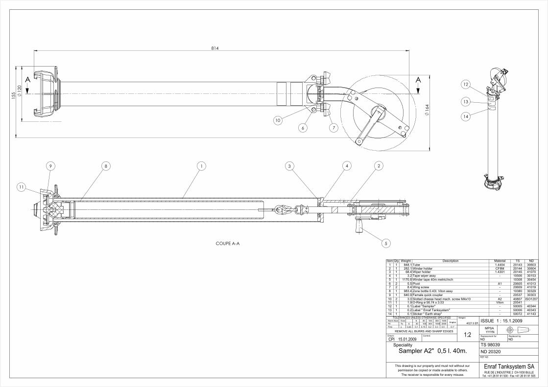
9.1 Sampler
O = Option, according to specific order.
ND TS DESCRIPTION
20319 10042 Hermetic Sampler A2-0,5 l. 30 m
30386 10302 Winder tape 30 m metric/inch
40796 10369 Tape assy w/o winder 30 m
20320 98039 Hermetic Sampler A2-0,5 l. 40 m
30454 10308 Winder tape 40 m metric/inch
41162 10392 Tape assy w/o winder 40 m
30329 10380 Zone Bottle 0,43 l. Viton assy
O 20246 20124 Bottom bottle 0.40 l FKM assy
O 20255 20137 Spot bottle 0.40 l. FKM
O 20254 20138 Running bottle 0.40 l. FKM
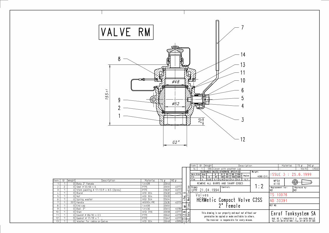
9.2 Valves
Important: Valves are supplied separately from Samplers. There are not included in Sampler scope of supply.
ND TS DESCRIPTION
20291 10083 Valve C2-SS-W, 2” flange DUJ, weather cap
20287 10082 Valve C2-SS-SEC, 2” flange DUJ, security cover
20288 10081 Valve C2-SS-BL, 2” flange DUJ, blind cover
30391 10076 Valve C2-SS-W, 2" female, weather cap
30374 10078 Valve C2-SS-SEC, 2" female, security cover
30596 10085 Valve C2-SS-BL G2" Female, blind cover