mini mac pi
TRANSCRIPT
Mini Mac PiCreated by Ruiz Brothers
Last updated on 2015-01-15 10:15:09 PM EST
244456677999
101010
12121313131415161619222223242425
Guide Contents
Guide ContentsOverview
Build Your Own �Mac PiHow it WorksProject AdvisoryChallenges and ExpectationsPrerequisite GuidesParts & ComponentsTools & Supplies
3D PrintingFDM 3D PrintingParts BreakdownPLA or ABS?Slicer Settings
Don't Have a 3D Printer?
CustomizationLike Modding CAD?Learning How-to use 123D DesignUsing Different ComponentsColors and Branding
Circuit DiagramPower Circuit for the Raspberry Pi Model BSpeakersTest Speakers
SoftwareAssembly
Add Magnets to partsMount PiTFT to Front BezelSecure Mini PiTFT to Front BezelPrep GPIO CableAdd GPIO Ribbon Cable to PiTFT
© Adafruit Industries https://learn.adafruit.com/mini-mac-pi Page 2 of 38
25262728282930303132333334353536373738
Secure Base to BodyPrep Wires for Slide SwitchSolder Wires to Slide SwitchSeal Wires with Heat Shrink TubingInstall Slide Switch to BasePrep Powerboost 500C for Slide SwitchSolder Slide Switch Wires to Powerboost 500CSolder Pi GPIO Wires to Powerboost 500CPrep JST Cable for BatterySolder JST to BatteryMount Powerboost to Bottom CoverTest Powerboost 500CTest PiTFTPosition GPIO Cable into BodyInstall Battery to BaseSecure Bottom to BaseBend Pi GPIO Ribbon CableInstall Raspberry Pi to PiTFTSnap on Front and Back
© Adafruit Industries https://learn.adafruit.com/mini-mac-pi Page 3 of 38
Overview
Build Your Own �Mac Pi
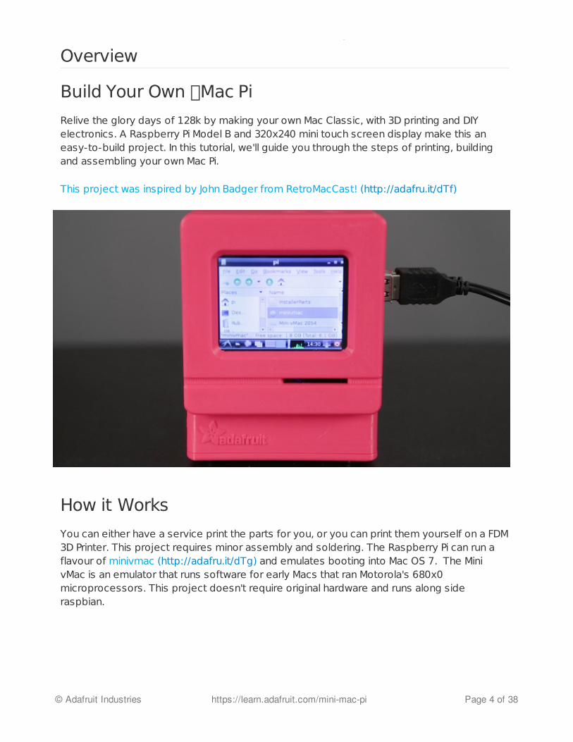
Relive the glory days of 128k by making your own Mac Classic, with 3D printing and DIYelectronics. A Raspberry Pi Model B and 320x240 mini touch screen display make this aneasy-to-build project. In this tutorial, we'll guide you through the steps of printing, buildingand assembling your own Mac Pi.
This project was inspired by John Badger from RetroMacCast! (http://adafru.it/dTf)
How it Works
You can either have a service print the parts for you, or you can print them yourself on a FDM3D Printer. This project requires minor assembly and soldering. The Raspberry Pi can run aflavour of minivmac (http://adafru.it/dTg) and emulates booting into Mac OS 7. The MinivMac is an emulator that runs software for early Macs that ran Motorola's 680x0microprocessors. This project doesn't require original hardware and runs along sideraspbian.
© Adafruit Industries https://learn.adafruit.com/mini-mac-pi Page 4 of 38
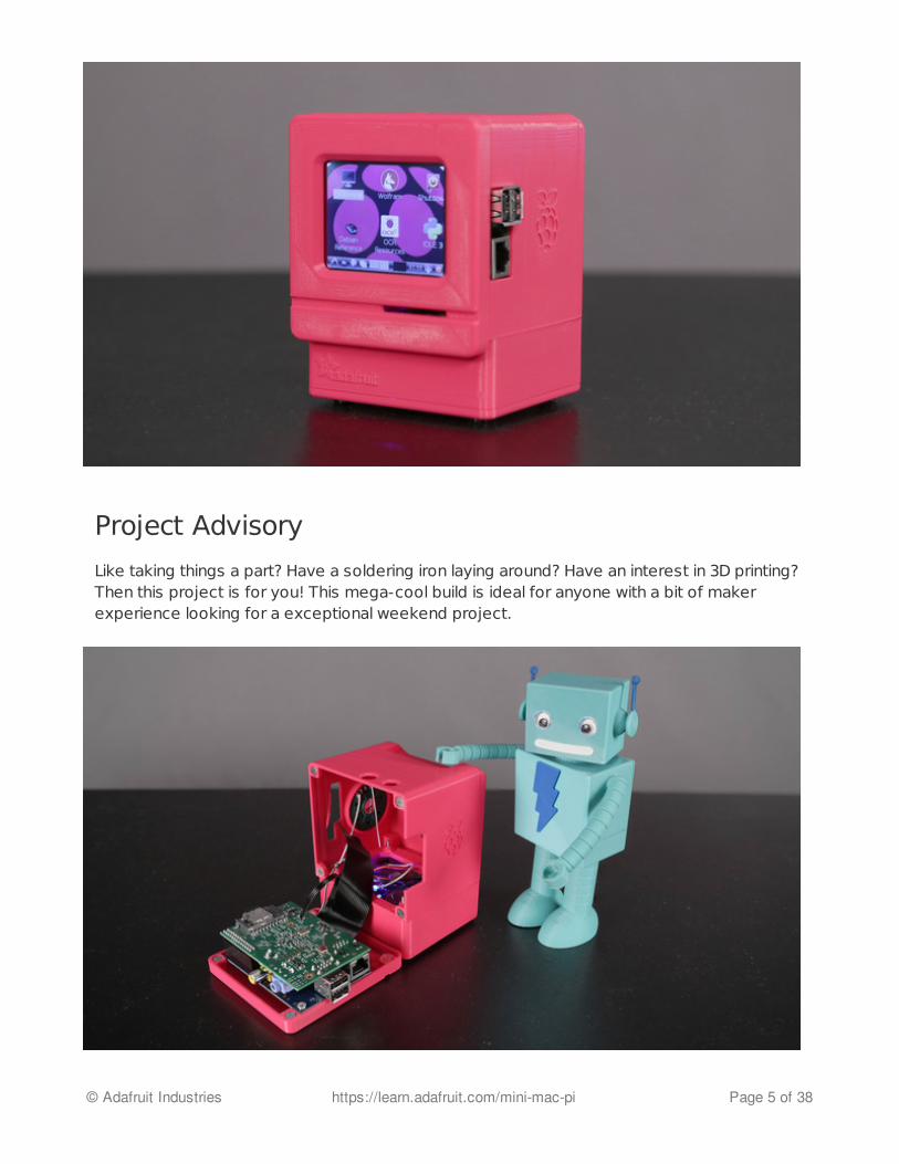
Project Advisory
Like taking things a part? Have a soldering iron laying around? Have an interest in 3D printing?Then this project is for you! This mega-cool build is ideal for anyone with a bit of makerexperience looking for a exceptional weekend project.
© Adafruit Industries https://learn.adafruit.com/mini-mac-pi Page 5 of 38

Challenges and Expectations
The most difficult part of the build may lie with the experience of the builder. If you are newto 3D printing and don't own one, you can still make this project by having a 3d printingservice make and ship the parts to you. If you are new to hardware like the Arduino andRaspberry Pi, you'll be glad to know there's only a minor bit of soldering and mostcomponents just connect together. Keeping this in mind, there are a few things to expect!
The Mac emulator does boot up and can run some basic apps but, there is:
Minor Application SupportNo Audio SupportOnly Mac 7No NetworkingScreen Size Cut to 320 x 240 so we can use the PiTFT (original was 512x342)
Prerequisite Guides
We recommend walking through the following guides to get you situated with the RaspberryPi and the Mini PiTFT 320x240 touch screen display.
Adafruit PiTFT (http://adafru.it/dTh)Learn Raspberry Pi Series (http://adafru.it/dTi)
© Adafruit Industries https://learn.adafruit.com/mini-mac-pi Page 6 of 38
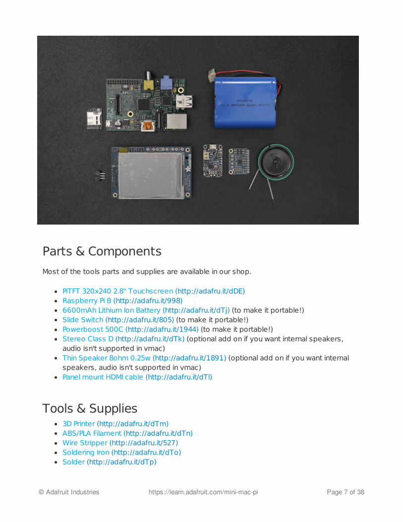
Parts & Components
Most of the tools parts and supplies are available in our shop.
PiTFT 320x240 2.8" Touchscreen (http://adafru.it/dDE)Raspberry Pi B (http://adafru.it/998)6600mAh Lithium Ion Battery (http://adafru.it/dTj) (to make it portable!)Slide Switch (http://adafru.it/805) (to make it portable!)Powerboost 500C (http://adafru.it/1944) (to make it portable!)Stereo Class D (http://adafru.it/dTk) (optional add on if you want internal speakers,audio isn't supported in vmac)Thin Speaker 8ohm 0.25w (http://adafru.it/1891) (optional add on if you want internalspeakers, audio isn't supported in vmac)Panel mount HDMI cable (http://adafru.it/dTl)
Tools & Supplies3D Printer (http://adafru.it/dTm)ABS/PLA Filament (http://adafru.it/dTn)Wire Stripper (http://adafru.it/527)Soldering Iron (http://adafru.it/dTo)Solder (http://adafru.it/dTp)
© Adafruit Industries https://learn.adafruit.com/mini-mac-pi Page 7 of 38

26AWG stranded wire (http://adafru.it/dTq)Pi GPIO ribbon cable (http://adafru.it/862)#4-40 flat phillips machine screwsScrewdriver set (http://adafru.it/dTs)Rare earth magnets 1/4 x 1/16 inch Disc N48
© Adafruit Industries https://learn.adafruit.com/mini-mac-pi Page 8 of 38
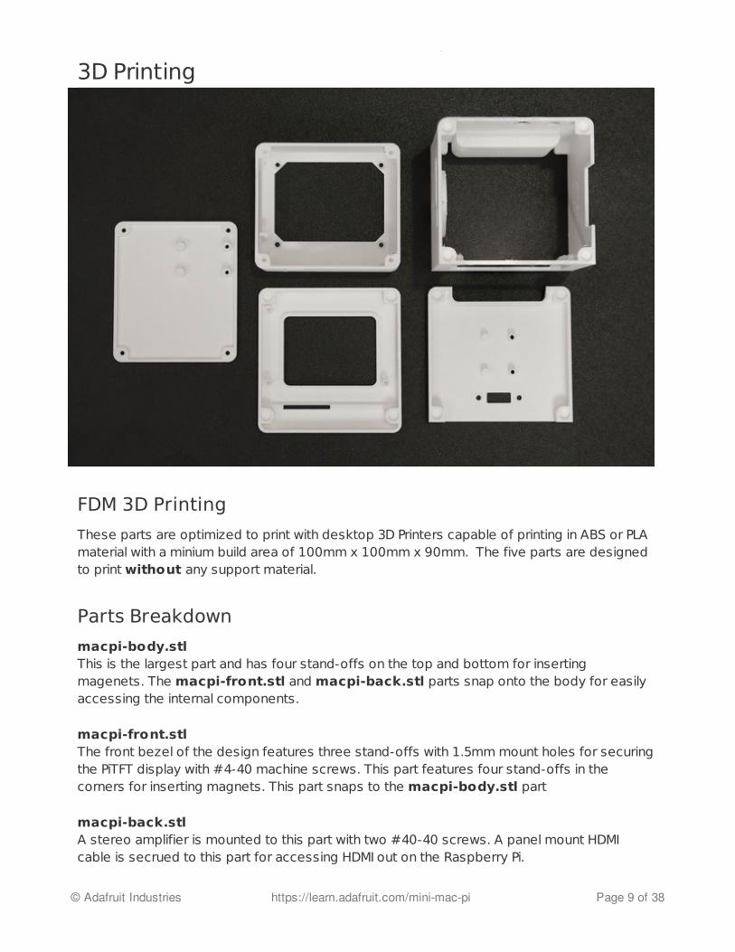
3D Printing
FDM 3D Printing
These parts are optimized to print with desktop 3D Printers capable of printing in ABS or PLAmaterial with a minium build area of 100mm x 100mm x 90mm. The five parts are designedto print without any support material.
Parts Breakdown
macpi-body.stlThis is the largest part and has four stand-offs on the top and bottom for insertingmagenets. The macpi-front.stl and macpi-back.stl parts snap onto the body for easilyaccessing the internal components.
macpi-front.stlThe front bezel of the design features three stand-offs with 1.5mm mount holes for securingthe PiTFT display with #4-40 machine screws. This part features four stand-offs in thecorners for inserting magnets. This part snaps to the macpi-body.stl part
macpi-back.stlA stereo amplifier is mounted to this part with two #40-40 screws. A panel mount HDMIcable is secrued to this part for accessing HDMI out on the Raspberry Pi.
© Adafruit Industries https://learn.adafruit.com/mini-mac-pi Page 9 of 38
macpi-base.stlThe battery and powerboost 500c are housed in this part. It is secured to the side of themacpi-body.stl part that has four mounting holes. #4-40 screws secure the macpi-base.stland macpi-body.stl part together.
macpi-bottom.stlThe powerboost 500c is mounted to this part with 2 #4-40 machine screws. This part issecured to the macpi-base.stl part with 4 #4-40 screws.
Download STLs
http://adafru.it/dUx
PLA or ABS?
We recommend printing the parts in PLA material. ABS prints tend to warp especially withsurfaces that feature filets and chamfers. Use either 1.75mm or 3mm diameter filaments,which ever your printer is optimized for.
Slicer Settings
The slicer settings are going to vary from printer to printer, but we recommend using thesettings below as a reference for tweaking the settings. The slicing settings was generatedusing MakerWare and the prints were tested on a makerbot Replicator 1 and Replicator 2.
Don't Have a 3D Printer?
Your neighbor or local hackerspace might have a 3D printer you can 'borrow'. There are afew great services that can print the parts out and ship them to you. Check out these belowor consult your own google search.
ShapewaysSculpteoi.materialise
macpi-back.stlmacpi-base.stlmacpi-body.stlmacpi-bottom.stlmacpi-front.stl
PLA @230c2 shells10% infill0.2mm layer height90/120 speeds
Takes about 6-8 hours to print all parts.
© Adafruit Industries https://learn.adafruit.com/mini-mac-pi Page 10 of 38

3DHubsMakeXZY
© Adafruit Industries https://learn.adafruit.com/mini-mac-pi Page 11 of 38
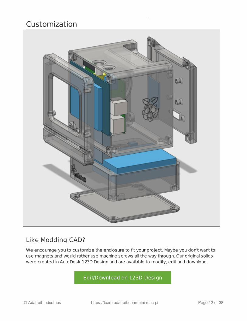
Customization
Like Modding CAD?
We encourage you to customize the enclosure to fit your project. Maybe you don't want touse magnets and would rather use machine screws all the way through. Our original solidswere created in AutoDesk 123D Design and are available to modify, edit and download.
Edit/Download on 123D Design
© Adafruit Industries https://learn.adafruit.com/mini-mac-pi Page 12 of 38
Learning How-to use 123D Design
123D Design is an easy to use, free CAD software from Autodesk, that is avilable in mostplatforms. It has an intutive interface and powerful features that are optimized for designingparts for 3d printing. There are plently of tutorial videos on youtube and we have a great liston our blog, everything from learning the interface to using the features.
Learn 123D
http://adafru.it/dPb
Using Different Components
Open source design means you're totally free to use whatever components you can find.We recommend using our components because we can offer support if an item isdamanged or broken.
Colors and Branding
The beauty of 3D Printing is you can print it in any color you want or change the color with alittle spray paint. Our design features the Raspberry Pi logo and includes the Adafruit logo onthe base. If a little STL hacking, you can add your name or logo to any part!
© Adafruit Industries https://learn.adafruit.com/mini-mac-pi Page 13 of 38
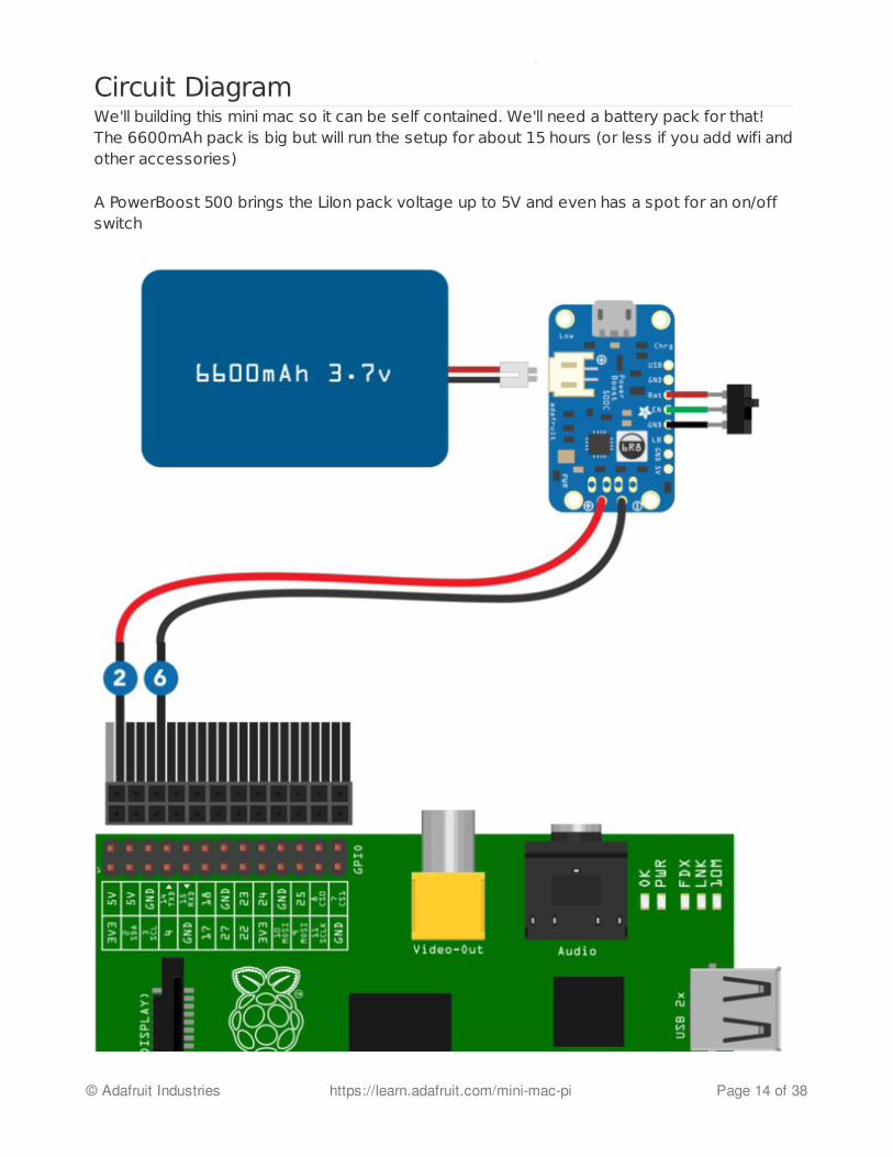
Circuit DiagramWe'll building this mini mac so it can be self contained. We'll need a battery pack for that!The 6600mAh pack is big but will run the setup for about 15 hours (or less if you add wifi andother accessories)
A PowerBoost 500 brings the LiIon pack voltage up to 5V and even has a spot for an on/offswitch
© Adafruit Industries https://learn.adafruit.com/mini-mac-pi Page 14 of 38
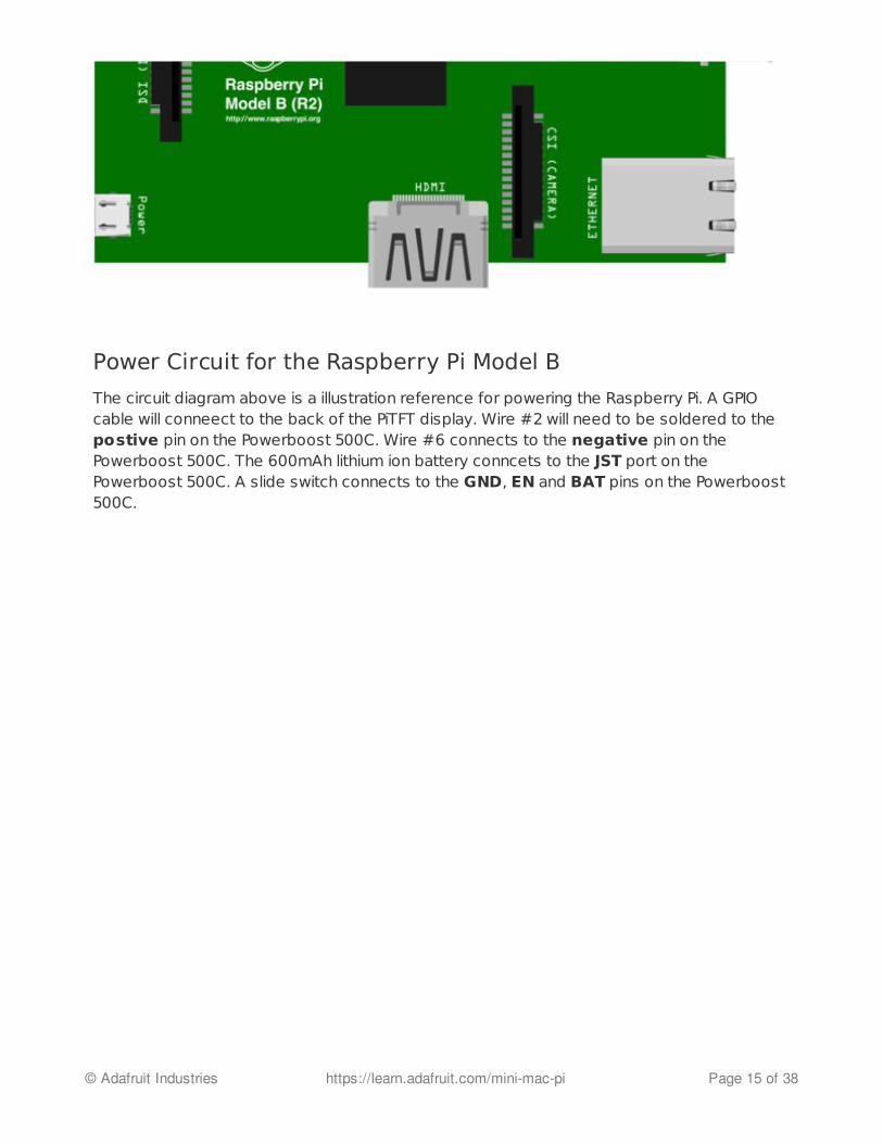
Power Circuit for the Raspberry Pi Model B
The circuit diagram above is a illustration reference for powering the Raspberry Pi. A GPIOcable will conneect to the back of the PiTFT display. Wire #2 will need to be soldered to thepostive pin on the Powerboost 500C. Wire #6 connects to the negative pin on thePowerboost 500C. The 600mAh lithium ion battery conncets to the JST port on thePowerboost 500C. A slide switch connects to the GND, EN and BAT pins on the Powerboost500C.
© Adafruit Industries https://learn.adafruit.com/mini-mac-pi Page 15 of 38

Speakers
Connect the speakers with the following connections:
connect VDD to VBAT on the powerboost 500connect GND to VND on the powerboost 500
see photo for audio connections:connect R+ or L+ to R or L on the raspberry pi (use thinblue wire)and connect R- or L- to Gnd on the raspberry pi (ditto)
solder speaker to amp (L out or R out, whichever youchose in the last step)
set both switches to ON (lowest gain!)
Test Speakers
© Adafruit Industries https://learn.adafruit.com/mini-mac-pi Page 16 of 38
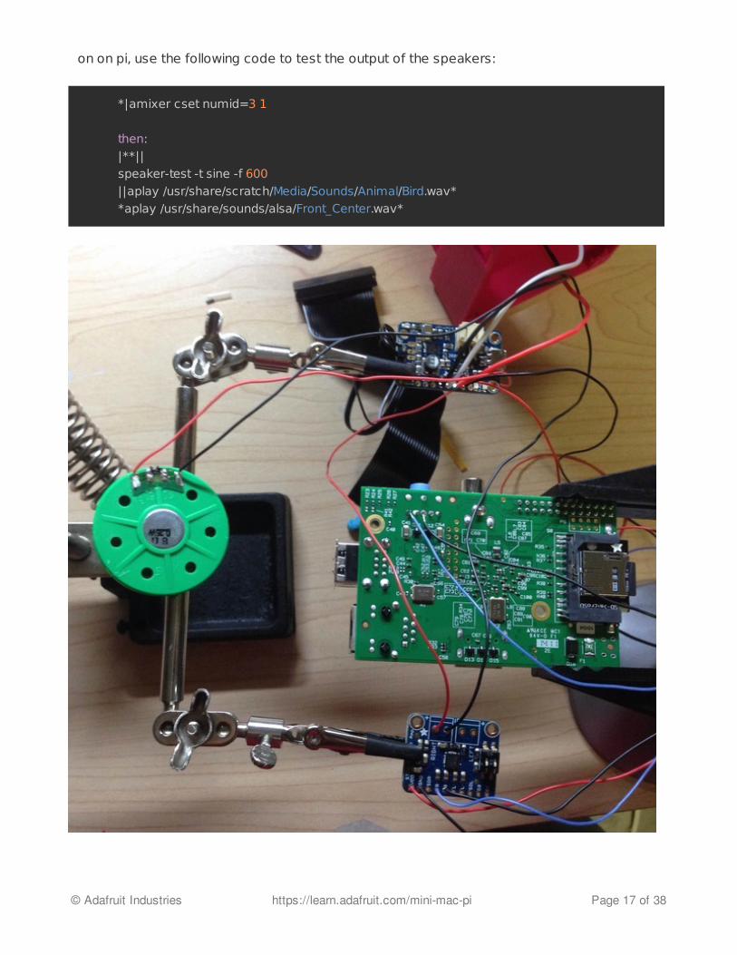
on on pi, use the following code to test the output of the speakers:
*|amixer cset numid=3 1
then:
|**||
speaker-test -t sine -f 600
||aplay /usr/share/scratch/Media/Sounds/Animal/Bird.wav*
*aplay /usr/share/sounds/alsa/Front_Center.wav*
© Adafruit Industries https://learn.adafruit.com/mini-mac-pi Page 17 of 38

© Adafruit Industries https://learn.adafruit.com/mini-mac-pi Page 18 of 38
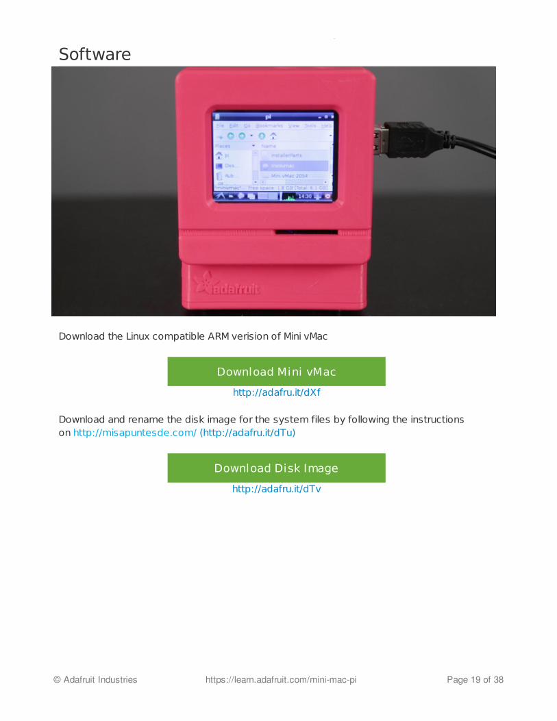
Software
Download the Linux compatible ARM verision of Mini vMac
Download Mini vMac
http://adafru.it/dXf
Download and rename the disk image for the system files by following the instructionson http://misapuntesde.com/ (http://adafru.it/dTu)
Download Disk Image
http://adafru.it/dTv
© Adafruit Industries https://learn.adafruit.com/mini-mac-pi Page 19 of 38
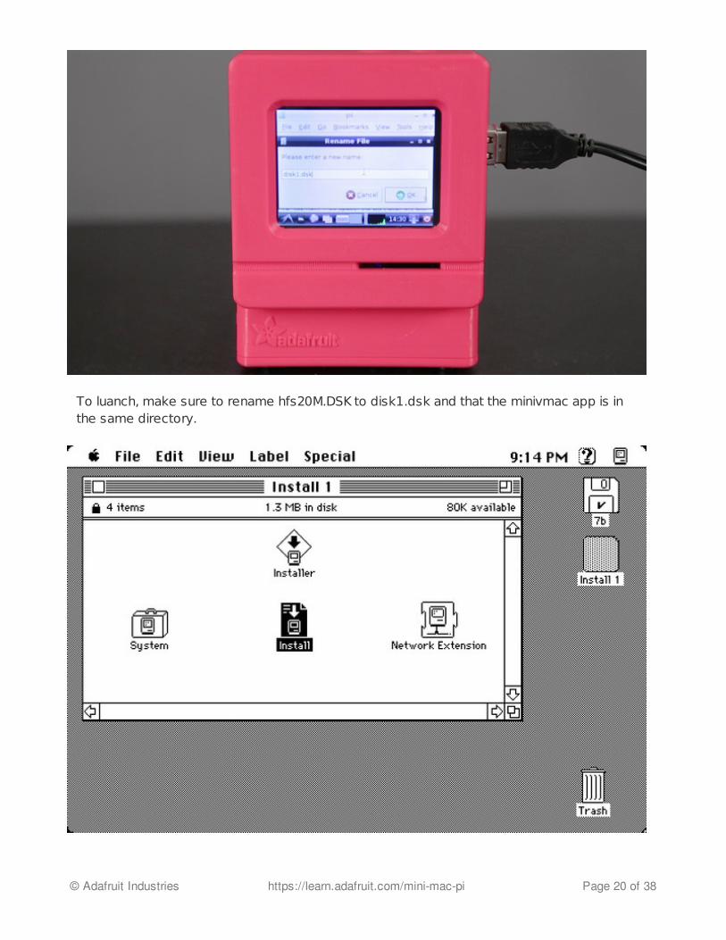
To luanch, make sure to rename hfs20M.DSK to disk1.dsk and that the minivmac app is inthe same directory.
© Adafruit Industries https://learn.adafruit.com/mini-mac-pi Page 20 of 38
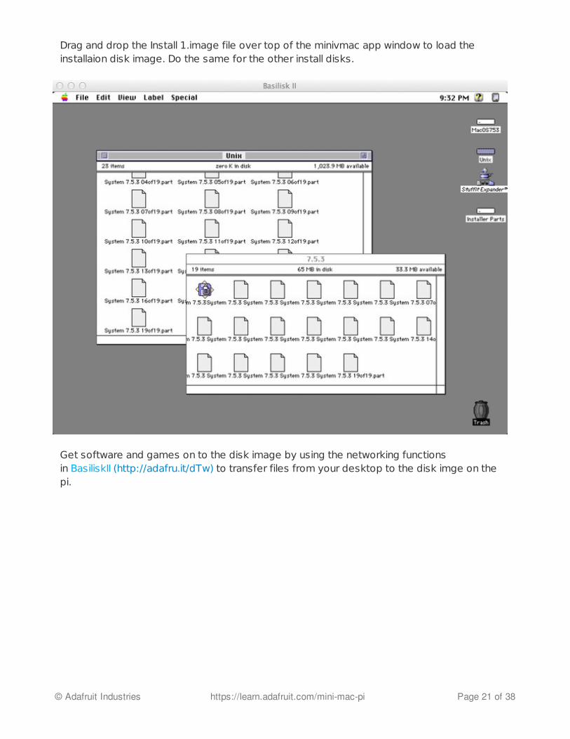
Drag and drop the Install 1.image file over top of the minivmac app window to load theinstallaion disk image. Do the same for the other install disks.
Get software and games on to the disk image by using the networking functionsin BasiliskII (http://adafru.it/dTw) to transfer files from your desktop to the disk imge on thepi.
© Adafruit Industries https://learn.adafruit.com/mini-mac-pi Page 21 of 38
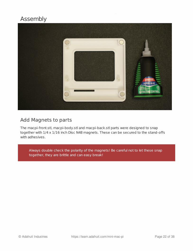
Assembly
Add Magnets to parts
The macpi-front.stl, macpi-body.stl and macpi-back.stl parts were designed to snaptogether with 1/4 x 1/16 inch Disc N48 magnets. These can be secured to the stand-offswith adhesives.
Always double check the polarity of the magnets! Be careful not to let these snaptogether, they are brittle and can easy break!
© Adafruit Industries https://learn.adafruit.com/mini-mac-pi Page 22 of 38
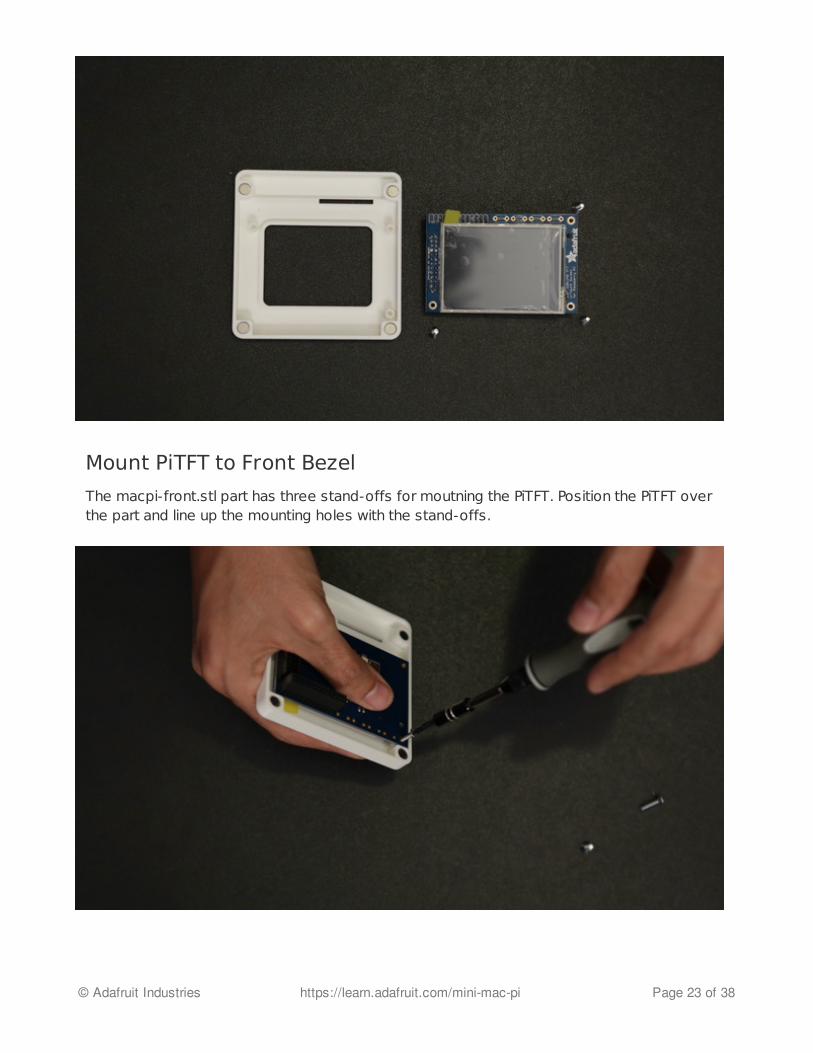
Mount PiTFT to Front Bezel
The macpi-front.stl part has three stand-offs for moutning the PiTFT. Position the PiTFT overthe part and line up the mounting holes with the stand-offs.
© Adafruit Industries https://learn.adafruit.com/mini-mac-pi Page 23 of 38
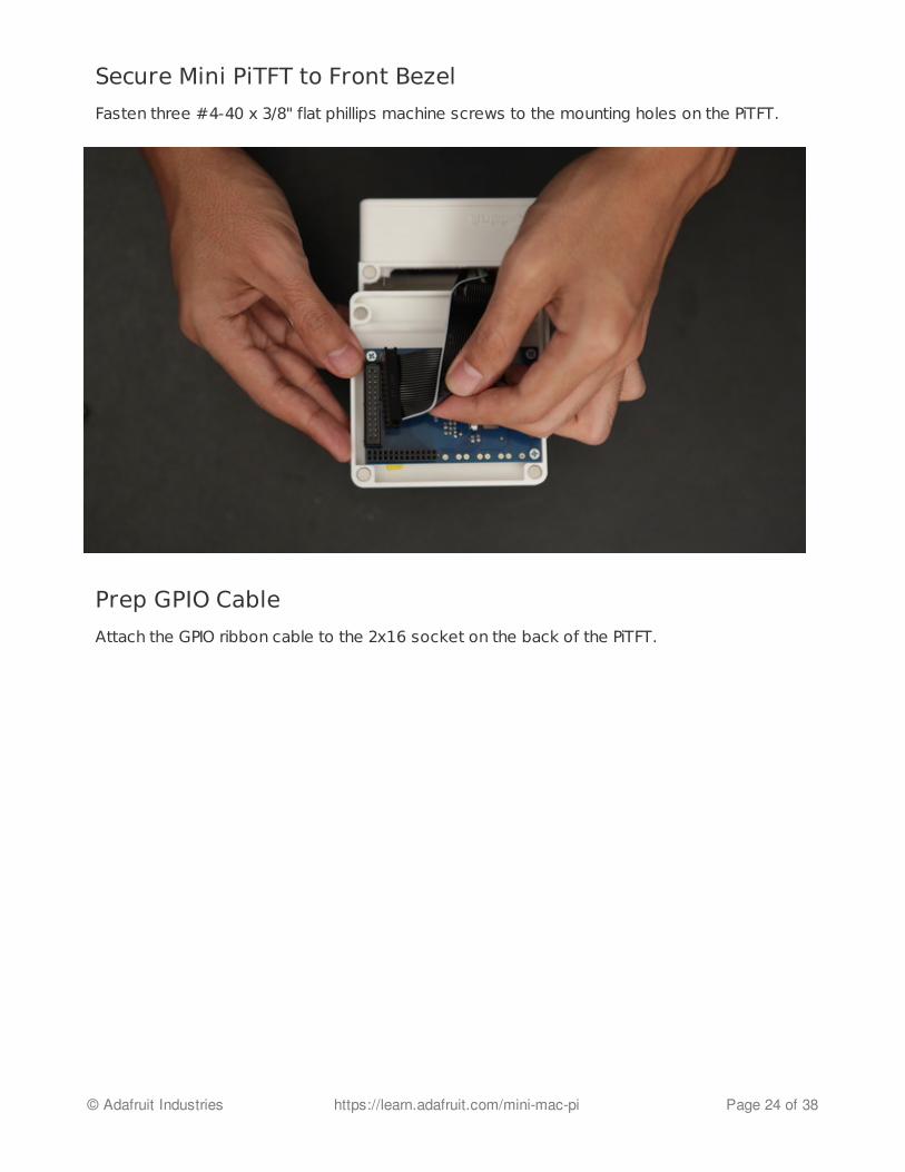
Secure Mini PiTFT to Front Bezel
Fasten three #4-40 x 3/8" flat phillips machine screws to the mounting holes on the PiTFT.
Prep GPIO Cable
Attach the GPIO ribbon cable to the 2x16 socket on the back of the PiTFT.
© Adafruit Industries https://learn.adafruit.com/mini-mac-pi Page 24 of 38

Add GPIO Ribbon Cable to PiTFT
Remove the connector on the end of the ribbon cable with wire cutters. Peel apart #2 and#6 wires from the ribbon cable. #1 is the wire with the white stripe.
Secure Base to Body
© Adafruit Industries https://learn.adafruit.com/mini-mac-pi Page 25 of 38
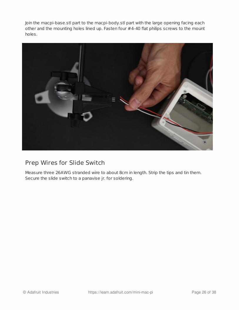
Join the macpi-base.stl part to the macpi-body.stl part with the large opening facing eachother and the mounting holes lined up. Fasten four #4-40 flat philips screws to the mountholes.
Prep Wires for Slide Switch
Measure three 26AWG stranded wire to about 8cm in length. Strip the tips and tin them.Secure the slide switch to a panavise jr. for soldering.
© Adafruit Industries https://learn.adafruit.com/mini-mac-pi Page 26 of 38

Solder Wires to Slide Switch
Connect the three wires to the slide switch by soldering the tips of the wires to the terminalsleads on the slide switch
© Adafruit Industries https://learn.adafruit.com/mini-mac-pi Page 27 of 38
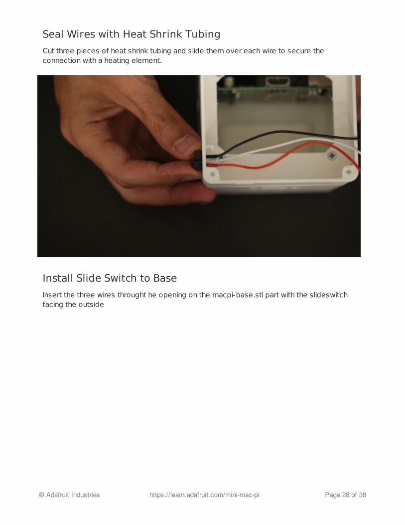
Seal Wires with Heat Shrink Tubing
Cut three pieces of heat shrink tubing and slide them over each wire to secure theconnection with a heating element.
Install Slide Switch to Base
Insert the three wires throught he opening on the macpi-base.stl part with the slideswitchfacing the outside
© Adafruit Industries https://learn.adafruit.com/mini-mac-pi Page 28 of 38
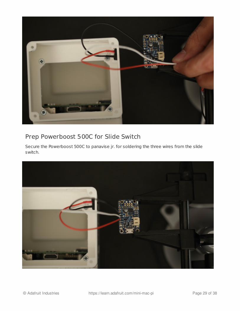
Prep Powerboost 500C for Slide Switch
Secure the Powerboost 500C to panavise jr. for soldering the three wires from the slideswitch.
© Adafruit Industries https://learn.adafruit.com/mini-mac-pi Page 29 of 38
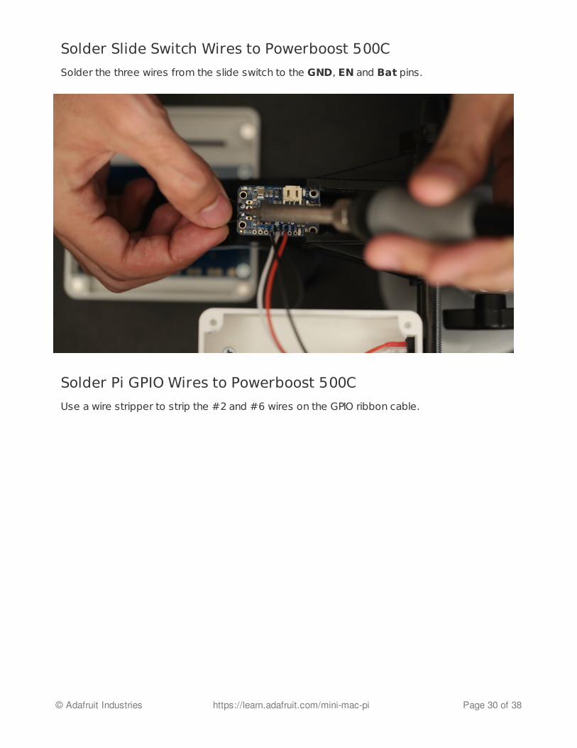
Solder Slide Switch Wires to Powerboost 500C
Solder the three wires from the slide switch to the GND, EN and Bat pins.
Solder Pi GPIO Wires to Powerboost 500C
Use a wire stripper to strip the #2 and #6 wires on the GPIO ribbon cable.
© Adafruit Industries https://learn.adafruit.com/mini-mac-pi Page 30 of 38

Powerboost 500C Conencted
Solder the #2 wire to the Postive+ pin and #6 to the Negative- pin on the Powerboost500C.
Prep JST Cable for Battery
© Adafruit Industries https://learn.adafruit.com/mini-mac-pi Page 31 of 38
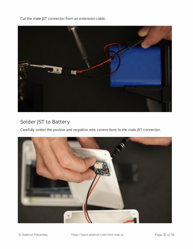
Cut the male JST connector from an extension cable.
Solder JST to Battery
Carefully solder the postive and negiative wire conenctions to the male JST connector.
© Adafruit Industries https://learn.adafruit.com/mini-mac-pi Page 32 of 38
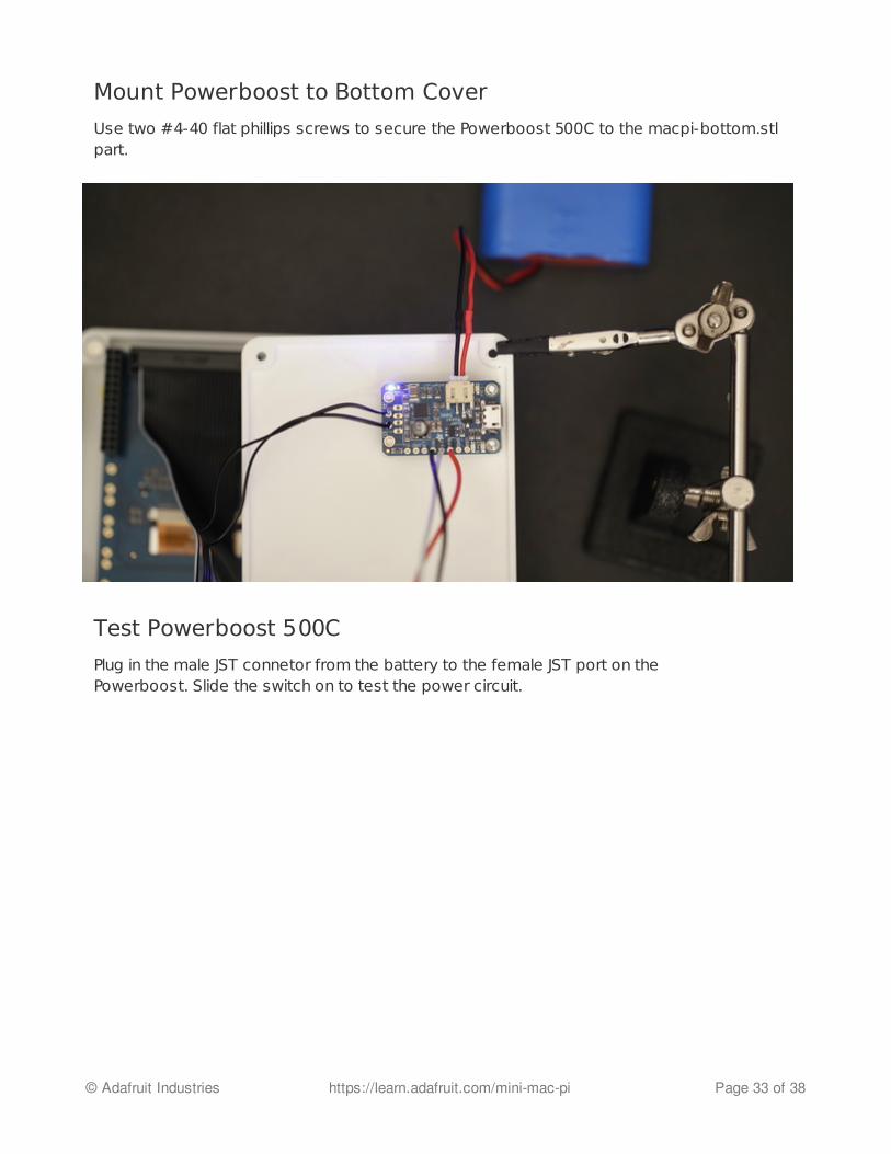
Mount Powerboost to Bottom Cover
Use two #4-40 flat phillips screws to secure the Powerboost 500C to the macpi-bottom.stlpart.
Test Powerboost 500C
Plug in the male JST connetor from the battery to the female JST port on thePowerboost. Slide the switch on to test the power circuit.
© Adafruit Industries https://learn.adafruit.com/mini-mac-pi Page 33 of 38
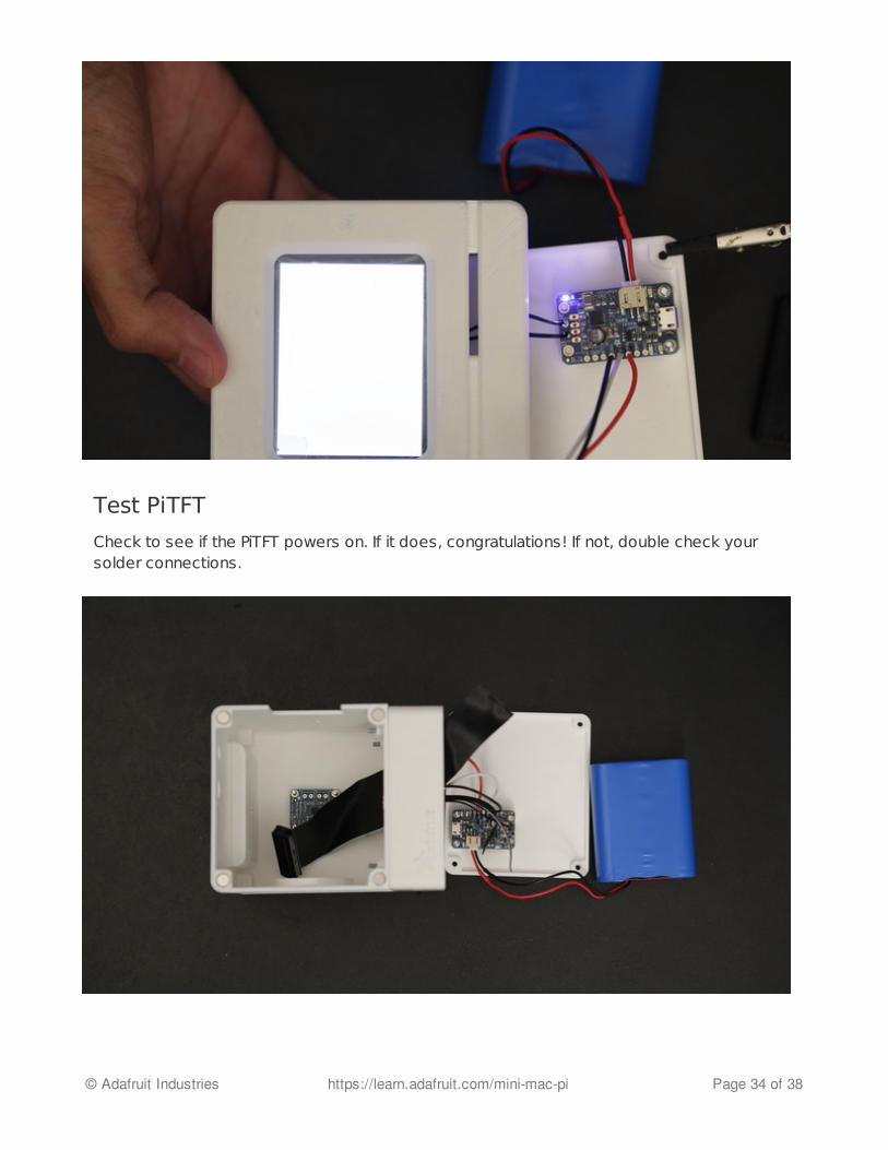
Test PiTFT
Check to see if the PiTFT powers on. If it does, congratulations! If not, double check yoursolder connections.
© Adafruit Industries https://learn.adafruit.com/mini-mac-pi Page 34 of 38
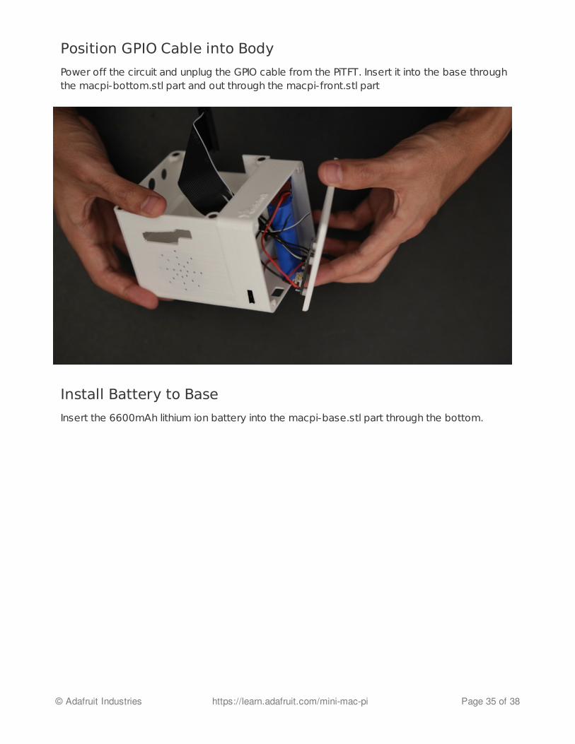
Position GPIO Cable into Body
Power off the circuit and unplug the GPIO cable from the PiTFT. Insert it into the base throughthe macpi-bottom.stl part and out through the macpi-front.stl part
Install Battery to Base
Insert the 6600mAh lithium ion battery into the macpi-base.stl part through the bottom.
© Adafruit Industries https://learn.adafruit.com/mini-mac-pi Page 35 of 38
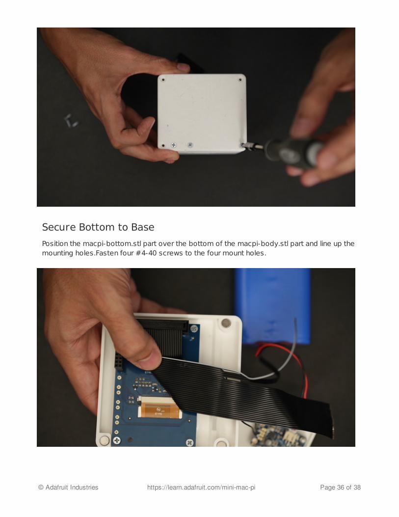
Secure Bottom to Base
Position the macpi-bottom.stl part over the bottom of the macpi-body.stl part and line up themounting holes.Fasten four #4-40 screws to the four mount holes.
© Adafruit Industries https://learn.adafruit.com/mini-mac-pi Page 36 of 38
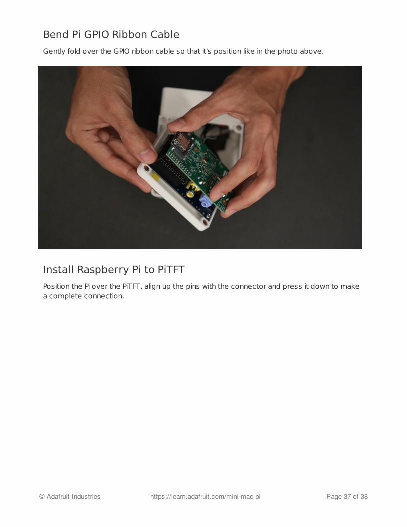
Bend Pi GPIO Ribbon Cable
Gently fold over the GPIO ribbon cable so that it's position like in the photo above.
Install Raspberry Pi to PiTFT
Position the Pi over the PiTFT, align up the pins with the connector and press it down to makea complete connection.
© Adafruit Industries https://learn.adafruit.com/mini-mac-pi Page 37 of 38

Snap on Front and Back
Carefully snap on the front and back parts to the body. The magnets are pretty strong andsecure the parts together nicely! It's easy to quickly remove the front or back and get to theinternals.
© Adafruit Industries Last Updated: 2015-01-15 10:15:11 PM EST Page 38 of 38