minewater module of i c a m p s software
TRANSCRIPT

MINEWATER module of I C A M P S software Revision 12-28-2009 Version 1.0 Ohio Automation 62971 Siverly Creek Road McArthur, Ohio 45651 (740)596-1023 Copyright (c) 1987-2009 by Ohio Automation All Rights Reserved.

TABLE OF CONTENTS
Overview...................................................................1 Section 1: General Notes and Warnings......................................2 MineWater Guidelines............................................4 Section 2: MineWater Menu..................................................5 2.1 Tools Menu..................................................6 2.2 Edit Menu...................................................6 2.3 Display Menu................................................7 Section 3: Node Menu.......................................................8 3.1 Define New Nodes.............................................8 3.2 Modify Node Parameters.......................................10 3.3 Move Nodes...................................................11 3.4 Find Node....................................................11 3.5 Erase/Delete Nodes...........................................11 3.6 List Nodes...................................................11 3.7 List Unused Nodes............................................12 3.8 Check for Duplicates.........................................13 Section 4: Branch Menu.....................................................14 4.1 Define New Branch............................................14 4.2 Modify Branch Parameters.....................................17 4.3 Erase/Delete Branch..........................................18 4.4 Move Multiple Branches.......................................18 4.5 Copy Branches................................................19 4.6 List Branches................................................20 4.7 List Pumps...................................................22
4.8 Configure Branches...........................................23 4.9 Find Node In Branches .......................................24 Section 5: Node/Branch Utilities...........................................25 5.1 Define/Edit Pumps............................................25 5.2 Set Controls.................................................27 5.3 Run MineWater................................................28 Section 6: Output Menu.....................................................30 6.1 Draw Quan/Press Output......................................30 6.2 List Pressure Output........................................31 6.3 List Quantity Output........................................31 6.4 Review Network Messages.....................................32 6.5 Reverse Selected Neg Branches...............................33 6.6 Reverse All Negative Branches...............................33 6.7 Edit Schematic..............................................34 Section 7: Symbols Menu....................................................32 7.1 Title Block.................................................32 7.2 North Arrow.................................................32 7.3 Scale Block.................................................37 7.4 Pump........................................................37 7.5 Valve-Open..................................................37 7.6 Valve-Closed................................................37 7.7 Check Valve.................................................37 Index......................................................................38

1
OVERVIEW The MineWater program is designed to analyze the flow of mine discharges through complex piping networks. The program can be used to evaluate the effects of alternate pumps, pipe sizes and flow routings in existing or proposed discharge systems. MineWater runs within AutoCAD and has pull down menus, toolbars and most of the information can be entered with the mouse or the digitizer puck. The preferred method for defining the pumping network is to work from as-mined and projections maps from your AutoCAD drawings. The nodes are picked up from the maps and because they are to scale, the system can automatically compute the length of each branch. The network can also be digitized from a hardcopy map of the mine, but the process is somewhat less convenient than working from the screen. The following figure is a diagram of the initial STARTUP menu which appears whenever the ICAMPS shortcut is executed. All the ICAMPS modules, e.g. MineWater, MineVent, and MineSimU can be accessed from this menu.

2
1. GENERAL NOTES AND WARNINGS
OSNAPS AND Z-VALUES The osnap feature of AutoCAD can be used to select nodes, numbers and branches. If areas of the drawing are cluttered the wrong entity may be selected. Use the osnap feature with caution. By default osnaps are turned off during the node selection process, but you can use the Tools menu to select the desired osnap. The node elevation or z-value is set to the value you select in the Digitize Node dialog box, so snapping to an entity that has a different z-value may cause the node elevation to be assigned to that value. The elevation of the branch polyline will be set to whatever you snap to i.e. the elevation of the node or if you snap to the endpoint of a polyline the elevation of the object you snap to. Also if you change the node elevation you must be sure to also change the elevation of the polyline vertices. To do this you may need to delete and re-insert the branch. DIGITIZER Working with a screen and mouse or a digitizing pad and puck are very similar operations. Both methods snap on to points selected with the cursor and/or keyboard. If you make use of the AutoCAD digitizing template, data entry can be limited to alphabetic information. See the AutoCAD instructions on setting up the digitizer template to match the screen. If you have sufficient floor space, to position the digitizer tablet more or less horizontally, the screen and keyboard can be placed on the tablet for easy viewing and access. Always check the screen to be sure that the proper point or data has been entered. WORKING WITH MINEWATER ENTITIES Never use the AutoCAD erase command to delete nodes and branches. Both are entities with associated attribute blocks and the AutoCAD erase command does not recognize these associations. If you use the AutoCAD erase command to delete a branch or node, you likely will be left with a corrupted drawing which is difficult to correct. Specifically the nodes are stored in a file called pnode.dat stored in the drawing directory. Never use the AutoCAD copy command to copy MineWater entities. A command called Copy Branches is provided to replicate existing nodes and branches in a new location.
AVOID THE WBLOCK COMMAND Never use the AutoCAD wblock command with MineWater drawings. Using this command to extract the branches will cause the handles of the polylines to change and the program will no longer know which attribute block goes with which polyline.
THE AUTOCAD USER COODINATE SYSTEM (UCS)
When inserting branches and nodes in MineWater you should always have the UCS set to World. Otherwise, your attribute blocks may end up somewhere other than where they should. Just type UCS at the AutoCAD command prompt to set the value to World. You can set it to what you need to when you are not entering MineWater entities.
OPENING MORE THAN ONE DRAWING AND THE SDI VARIABLE When working with MineWater drawings you should only have one drawing open at a time. Otherwise the pnode.dat file mentioned above will become corrupted between the two drawings and you will get duplicate nodes which can cause a multitude of problems. When any ICAMPS shortcut is invoked it will set the Single Document Interface (SDI) variable to 1, which limits you to only opening one drawing at a time. If you need to open more than one drawing in regular AutoCAD you can type SDI at the AutoCAD command prompt and set this variable back to 0. As long as the SDI variable is 0 or 1 the user can change it, but if it is 2 or 3 then that means that AutoCAD has determined that there are applications loaded that require only one document to be opened. In most cases you can set the SDI variable to 0 and open more than one drawing while in MineWater but you should be careful not to use the MineWater functions while having more than one drawing open.

3
AUTOCAD COMMAND ABBREVIATIONS IN MINEWATER
a draw arc by three points aa edit attributes one at a time ap edit attributes one at a time av edit attributes one at a time b break c draw circle by two points or key-in diameter or radius ch change cf chamfer cr color cy copy d dimension DD edit definition block dd edit definition block ds distance between two points er erase ex extend f draw fillet h draw cross-hatch i insert block l draw line la change layer settings lf freeze layer li line information lo layer off ls layer set lt thaw layer m move m1 move to another layer o offset p draw polyline pe polyline edit r redraw rg regenerate rt rotate CR change current layer color s save sc scale t trim tx insert text vd delete view vr restore view vs ave view za zoom all zd zoom dynamic ze zoom extents zp zoom previous zw zoom windows

4
MINEWATER GUIDELINES Currently the program generates a static solution showing flow rates through pipes, and pressures at pipe junctions (calculated using the Hazen-Williams headloss formula) for a fixed input condition. Ultimately the program will generate simulations of a system over time, allowing for control sequences such as the starting and/or stopping of pumps under specified conditions or at specific times. The program interface is very similar to that of Ohio Automation’s MineVent, as is the data output, and should be generally familiar to users of that program. The key user tasks in constructing a MineWater network are digitizing nodes (See Section 3), drawing and describing branches (Section 4), and describing the operating characteristics of existing and/or proposed pumps (Section 5). The program stores up to 12 pre-defined pipe classifications which are assigned separate layers for display purposes; for user convenience, it is best to configure the “typical” pipes found in the system (categorized at the user’s discretion by material, size, condition and/or roughness coefficient) before starting to construct the network model (Section 4.7). Digitizing Nodes [Node Menu/Define New Nodes...] - Nodes are placed on the mine map wherever there is a junction of two or more branches (pipes) or where branch characteristics change (e.g. - pipe size or pipe resistance). In addition, nodes are placed where a branch discharges (e.g. - intermediate sumps) or begins (e.g. - at a measured inflow or unlimited source). There are three distinct node “types” used in MineWater, but they are all activated through the same dialog box and their application is transparent to the user. Node Type "Junction" is used where pipes join or change characteristics; it is also useful for any point in the system where pressure prediction may be desired. Node Type "Source" is used to represent a known inflow to the system (e.g. - a scavenger pump pick-up point or a gravity inflow to a sump). Node Type "Sump" is basically a storage tank into which water may flow or be pumped, and from which water is withdrawn by a pump and injected into the system. Defining Branches [Branch Menu/Define New Branches] - Branches are drawn on the mine map between nodes and should approximate the actual pipeline route for greatest accuracy. (Note that nodes do not
need to locate nodes at points where a branch changes direction only.) Two key factors here are the branch “Type” (pipe or pump) and “Status” (open, closed or check valve). For a "Pipe" the user selects a “Code” from a pre-defined configuration list, which automatically inserts the appropriate “Diameter” and “Roughness. For a "Pump" the user selects an appropriate pump curve from another pre-defined list. Both pipe configurations and pump curves can be defined by the user as best-suits his/her needs.
Defining pump curves is accomplished through “Define/Edit Pumps...” in either the “Node” or “Branch” menu. Characteristic performance curves for most pumps can be obtained from the various pump manufacturers. The program allows for the definition of up to 50 pumps, at the user's discretion. Note that entering a meaningful make and model is very handy when it comes to assigning the right curve number to a “Pump” branch! The hydraulic characteristics of “typical” branches can be described in “Branch Menu/Configure Branches...” for ease in defining new branches. The user has a great deal of flexibility in assigning how branches are to be displayed; the only limitation is the 12 available layers. He/she can group all pipes of a certain diameter (for example) in one code/layer, or further subdivide the system by assigning pipes of different diameters and different materials to separate codes/layers. One (or more) code/layer can be reserved for displaying the location of pumps, or other branches of particular interest. To run the model, “Run MineWater...” can be selected from either the Node or Branch menu, or using the “hot button” in the MineWatr toolbar to the left of the screen. This brings up a dialog with potential options; at present, the user should accept all defaults and just “Run MineWater”.

5
2. MINEWATER MENU MineWater has pull-down menus and icon toolbars as shown below. The first three headings on the left (Tools, Edit and Display) contain some useful AutoCAD commands. The main MineWater features that are most commonly used are the Node Menu, Branch Menu and Output Menu. The Symbols menu consist of annotation drawings such as pumps, check valves, sprays, title blocks etc.. The File Menu contains options for manipulating files and menus. All of these options will be discussed in detail later.
The icons correspond to the following functions: Insert Node | Define Branch | Modify Branch | Set Controls | Run MineWater | Draw Q&P | List Pressure
List Quantity | List Pressure Drops

6
The contents of the first three Pull-Down commands follow:
2.1 Tools Menu
The Tools menu is mainly used for on-the-go osnapping. For example, if the osnaps are OFF and you want to quickly snap to an intersection you can just go to Tools-->INTersec and then snap to the intersection then osnaps are turned back off so that it is a quick one time use of osnaps. If you want to make osnaps "permanent" then select OSNAP first and then the desired snap mode. For example if you are entering several nodes and need to snap to intersections then select OSNAP first and the select INTersec. To turn osnaps back off then select OSNAP then NONE. The other useful features of the Tools menu is the Cancel command, Undo, Redo, and Redraw. A word of caution is that you should be very careful using Undo and Redo in MineWater drawings. If you erase a node with the MineWater Erase Node command and then do an undo you may end up with a node that is in the drawing but not in the node file which can cause duplicate nodes and other issues. So it is highly advised that you do not use the Undo and Redo unless you know that you are working on parts of the map that have no affect on MineWater entities such as nodes, attribute blocks, branches and arrows.
2.2 Edit Menu
The Edit menu has several useful AutoCAD commands. As noted earlier you should be careful with the Erase command as well as the copy command when working with MineWater entities. The rest of the commands here can be used with relative safety. Of course you do not want to delete any of the MineWater layers such as Attribs, Pstype*, or Watr* (where the * implies other letters and numbers). Also you should never Explode any MineWater entities namely nodes or branches unless you know what you are doing and have a good reason to do so.

7
2.3 Display Menu
The Display menu has the most commonly used Zooming and Panning features of AutoCAD. As well as a menu option called Drawing Aids which is essentially the AutoCAD Drafting options dialog box where you can change grids, snap modes, polar tracking and more. The Modify Layer option can be used to access the AutoCAD layer manager where you can turn on and off layers, freeze them, set the current layer, set layer colors and other options depending on your version of AutoCAD.

8
3: NODE MENU The Node Menu options allows you to create or modify the node data. The following pull down menu appears when you select this option.
MineWater Junction, Source and Sump nodes, hereafter referred to as nodes, can be digitized directly from an AutoCAD drawing of the mine layout. If you do not have the map on the computer, the nodes can be selected off a hardcopy by using a digitizer. The program will work interactively with the digitizer. Nodes are placed on the mine map wherever there is a junction of two or more branches (pipes) or where branch characteristics change (e.g. - pipe size or pipe resistance). In addition, nodes are placed where a branch discharges (e.g. - intermediate sumps) or begins (e.g. - at a measured inflow or unlimited source).You do not have to enter a node everywhere the branch changes direction. When you choose this option the following dialog box appears.
3.1 Define New Nodes...

9
To insert a node, enter the node Name, Elevation and Type. Node Number: The node number will default to the next available node number, but you can change the node number before selecting the location. If you use a duplicate node number the program will set it to the next available node number and give you a warning. Name: The node name is not necessary but for the users convenience he/she can assign a name to a particular node of interest. The node name should not exceed 20 characters. Elevation: The program expects an elevation for each node, which is used in the pressure calculation. This is not critical for Junctions, since the flow through a system is dependent primarily upon system inlet and outlet elevations, energy inputs and line losses, but it is useful in conjunction with actual pressure readings taken in the system for model validation. Type: There are three Types of nodes. ** Node Type “Junction” is used where pipes join or change characteristics. This is the default option when the
“Define New Nodes...” dialog box is opened. ** Node Type “Source” is used to represent a known inflow to the system (e.g. - a scavenger pump pick-up
point, or a gravity inflow to a sump). Elevation here is important, especially for a pump pick-up, and a measured or estimated flow rate is required. If the “Source” is essentially an unlimited body of water, the “Source” is designated as a “Pool” (by checking the “Pool” box), and only the pool elevation is needed.
** Node Type “Sump” is basically a storage tank into which water may flow or be pumped, and from which
water is withdrawn by a pump.
For a sump, the program requires an elevation (at the bottom of the sump, not at the mine floor), an “area”
(presently assumed to be uniform with depth -- use an average), a “min[imum] level” (the lowest point to which the sump can be drawn, as measured in feet ABOVE the sump elevation), a “max[imum] level” (the highest level, again ABOVE the sump elevation, to which the sump can fill), and an “init[ial] level” (Note this value will be critical for simulations with “Controls”; at present any value between the “min. level” and

10
the “max. level” is acceptable.) Pick Node Location: When you select Pick Node Location the following prompt appears. Enter Node/<R> to End Left click the node location at the prompt to insert the node. The system places the node number next to the node. The node can be re-positioned with the AutoCAD move command and thereafter it will appear in the selected location. To move only the node number you can use Output-->Edit Schematic and select the Move Attribute button and select the number (not the circle!). NOTE: Frequently you want to see the coordinates of nodes as they are entered. If the coordinates are not displayed (on the lower left of the screen in the status bar for most versions of AutoCAD) as you move the cursor, right click on the coordinates in the status bar to turn on the Coordinates Display function. The check boxes at the bottom of the dialog box allow you to hide or show the node number, pressure and name of the node you are defining or editing. By default the number and pressures are shown and the name is hidden. Note the pressures will not show up until after you run MineWater and use Draw Quan/Pres Output under the Output menu.
This option is used to edit the information associated with the existing nodes on the drawing. When you select this option a dialog box similar to the following appears.
3.2 Modify Node Parameters...
The first thing you must do is select the node you want to modify using the Pick Node button. The only node attribute that cannot be changed is the node number. Note: If you change the elevation of the node be sure to delete and re-insert any branch attached to the node. After you make the desired changes you can select Update Node to save the changes.

11
If you make changes and do not select Update Node you will see the following dialog box and have another chance to save the changes. Either way it amounts to about the same amount of mouse clicks.
Clicking the Yes button on this dialog box saves the node information in the drawing.
Use this option only to move nodes which are not connected to branches. If branches are connected to the node delete the branches which are connected to the node (using the Erase/Delete Branch option), move the node and then recreate the branches. As an alternative, use the Move Multiple Branches option under the Branch menu. When you select this option the following command line prompt appears:
3.3 Move Nodes
Select objects:
Position the pick box on the circle, node number, or pressure value and click the left mouse key hit the enter key once after selecting the node and drag the node to the desired position. You can actually move more than one node at a time by picking several nodes at the Select objects prompt, but this is not recommended unless you are careful. Note: To change the size of the pick box you can type pickbox at the AutoCAD command prompt.
This option helps you locate a specific node in the drawing. The following command prompt appears: 3.4 Find Node
Node Number to Find <0>: If you enter an existing node number, a green arrow will appear at the node location and the coordinates will shown on the status bar. The following prompt will appear allowing you to either stay zoomed in to the node that was found or zoom back to the previous view. Zoom Previous (Yes/No) <Yes>: If the node number you entered does not exist then nothing happens and you are returned to the AutoCAD command prompt.
Use this option to delete a node or nodes. Do not use the AutoCAD erase command to erase nodes as this will not update the pnode.dat file. When you select this option, the following command line prompt appears:
3.5 Erase/Delete Nodes
Select objects:
You can keep selecting nodes to delete and when you are finished you can just hit Enter or Esc to exit the function. Important: If you delete a node, any branch which depends on that node will not be deleted. You must also delete that branch or the MineWater calculation will report errors and terminate.
Select this option to display the existing node numbers. All nodes in the drawing will appear. Use Option 3.7, List Unused Nodes to list any unreferenced nodes, that is, nodes which are not connected to branches. Each node number and its X and Y coordinates, Elevation, Type and Flow value will appear in a dialog box list as shown in the
3.6 List Nodes...

12
following example. It also gives you the opportunity to print the list to a printer or a file You can also use this function to find and view nodes on the list in the drawing. This feature is useful for verifying that the node coordinates are reasonable.
The first pull-down menu on the left allows you to select the node Type of the nodes you want to view in the list. The next option allows you to edit the node. If you need to edit several nodes this feature can save time. To exit the dialog box click Done.
Select this option to display the unused node numbers. Nodes that are in the drawing but not connected to any branch, called unreferenced nodes appear on the left and node numbers that are not assigned to any node are on the right as shown in the following example. You can delete all the unreferenced nodes or print the list to a printer or file.
3.7 List Unused Nodes...

13
This option checks for duplicate nodes on the drawing. The normal response is "No Duplicate Nodes Found"; If you have a duplicate node you have probably used the AutoCAD copy command by mistake.
3.8 Check for Duplicates

14
4: BRANCH MENU The Branch menu allows you to create or modify the branches, branch data and defaults. The following pull down menu appears when you select this option.
When you select this option the following dialog box appears. You can create new branches as well as modify any of the branches you have created within the same Define New Branches session.
4.1 Define New Branches...

15
To create a new branch, fill in the edit boxes on the left. Name: The branch name is not necessary but for the users convenience he/she can assign a name to a particular branch of interest. The branch name should not exceed 20 characters. Type: Select the branch type, either pipe or pump from the drop down list. ** Branch Type “Pipe” is used to describe pipe characteristics. The “Length” is automatically calculated as the
branch is drawn, but can be changed by the user. The “Size” is entered as diameter in inches and the “Roughness” is the “C-factor” for the pipe. This data is automatically entered as pre-defined in “Branch Menu/Configure Branches...” when the branch Code is selected.
** Branch Type “Pump” is used to designate pump locations. As with pipes, the “Pump” is drawn between two
nodes -- but the “Length” is disregarded. The “Status” of a pump should be either “Open” (running - the default) or “Closed” (not running). The appropriate pump curve number can be selected in “Curve”. If the pump is a constant-volume (e.g. - piston type) unit, the “Use Power” box should be checked and the effective horsepower (after drive losses) should be entered. If the pump is variable speed, to represent its operation in MineWater, the appropriate pump curve number is selected, then the speed relative to the base curve is entered in the "Speed" box (i.e. - if the pump is running at twice "normal" speed, enter Speed: 2,; if half speed, 0.5).
Code: Select the code from the drop down list. Code names and associated default information, line type, color, material, diameter, condition and roughness coefficient information can be set using "Configure Branches..." When you select a code the diameter, roughness, and color default to what is set in "Configure Branches..." but can be changed by the user for each unique branch. The branch will be drawn on the layer assigned in "Configure Branches..." (i.e. layer PSTYPE1 through PSTYPE12). Curve: If the branch type is a pump and you are not using Power select the pump curve that was created in Define/Edit Pumps. This drop down list shows the Pump reference number, make and model as defined in Define/Edit Pumps. If the branch type is a pipe this option is not applicable and is grayed out. Power: This option is only available if the branch type is a pump and the Use Power check box is checked. If the pump is a constant-volume (e.g. - piston type) unit, the Use Power box should be checked and the effective horsepower (after drive losses) should be entered. Use Power: Check this box to enter a horsepower for the pump(see above). Speed: If the pump is variable speed, to represent its operation in MineWater, the appropriate pump curve number is selected, then the speed relative to the base curve is entered in the Speed edit box (i.e. - if the pump is running at twice "normal" speed, enter Speed: 2,; if half speed, 0.5). Diameter: Size or diameter of the pipe in inches. Default is set to the value entered in Configure Branches. Roughness: This is the “C-factor” for the pipe -- automatically entered as pre-defined in Configure Branches. Status: The status of a pipe can be Open (the default) or Closed (valved off, allowing a connection to be described in the system without actually being used), or it can be a C[heck] V[alve] (allowing flow only in the direction in which the pipe was originally drawn). Note that if an unused branch contains a check valve, it might better be described as two branches in series - one Closed and one CV - so that the Closed branch can later be Opened and still controlled by the CV. The status of a pump can either be Open (default- running) or Closed (not running). Length: The length of a pipe is automatically calculated but can be changed by the user. The length of a pump is disregarded. Color: The color defaults to the color associated with the code that is set in Configure Branches. However, the color does not have to be BYLAYER and set by the code, each branch can have a unique color.

16
Hide Quantity & Hide Name: These check boxes allow you to either show or hide the quantity and the name. Quantities will not show up until after you run MineWater and use the Draw Quan/Pres option under the Output menu. >Pick Nodes/Add Branch<: When you click this button, the following series of command line prompts appear Pick Start Node/<R> to end You must have previously defined the start node After you pick the start node, the command line prompt
changes to the following. Pick [End Node/ Bend Point]/<R> to end The branch must end at a node you previously defined, but the line representing the branch can follow the
actual pipeline routing. Pick the points (called bend points) where the pipe changes direction in the order in which they will be connected.. When you pick a point which is not an actual Node, the command line will prompt for an elevation, offering as a default the elevation of the previous point. After you provide the elevation, the above prompt reappears and a line will be drawn between the points you have chosen. The End node must be one of the active nodes you previously defined. After you pick the End node press the Enter key to indicate the end of the branch. Note: If you are defining several branches you may want to set up AutoCAD to associate the right mouse button with the Enter key. This will save you time from constantly having to hit Enter on the keyboard and you can define all your branches using just the mouse. To set this type config at the AutoCAD command prompt select the User Preferences tab, click the Right Click Customization button and then select the Turn on Time Sensitive Right Click checkbox. This may vary on different versions of AutoCAD or it may already be set.
When you indicate the End node has been picked, the new branch will appear highlighted at the bottom of the list. If you indicate the true pipe path, the length of the pipe can be calculated
If you select a Sump node as the start node or end node, you will get additional questions after you have selected the start and end nodes. If the Sump node is the end node and the branch type is pipe then the program will show the following prompt: Discharge Open (Y/N)?: <Yes>: If the pipe discharge is below the maximum water level in the sump, enter "no", otherwise accept the default. If the Sump node is the start node and the branch type is "Pipe" then the program will show the following prompt: Is this a suction line(Y/N)?: <Yes>: If the pipe is directly connected to a pump and the end of the pipe is always under water accept the default. Change/Update Branch: Ordinarily, all descriptive branch data should be put in before the branch is drawn. (Note: The branch length will be calculated and entered in edit box after the branch is drawn). If any branch descriptive data is entered or changed after the branch has been drawn, hit Change/Update Branch for the new data to take effect. Any of the branches in the list can be edited. Highlight the branch by clicking on the corresponding line and the branch parameters will appear in the edit boxes on the left. After you make your changes, click the Change/Update button to save the changes. View Branch: Any branch in the list can be viewed. First highlight the branch you want to view and click the View Branch button. The MineWater diagram will be zoomed in where the branch is located with a green arrow pointing at the branch attribute box and its flow arrow. The command line prompt defaults to Zoom to the previous window.

17
Delete: Any branch in the list can be deleted. First highlight the branch you want to delete and click the Delete Branch button. OK: Click OK to save all the branches in the list and make them a part of the network. You can erase them later if you need to. Cancel: Click Cancel to remove all the branches in the list, that were defined in the current Define New Branch session, from the network. CAUTION: Hitting cancel will delete all the branches that you have defined in the current Define New Branches session. You will not be asked if you are sure that you want to delete.
When you select this option a dialog box similar to the following appears. 4.2 Modify Branch Parameters...
To start the process, click the Pick Branch Attribute Block button. The following command line prompt will appear:
Select Branch Attribute Block If you have trouble picking the correct block in a cluttered area zoom in closer and select the block (or the associated quantity if the calculation has been run and displayed previously) . You can change any of the Branch parameters that are not grayed out. See the Define New Branch option above for the instructions to change the Branch parameters. The other buttons provide the following options: Reverse Branch: This option is used to reverse the branch start node and end node and change the direction of flow. This will also relocate the branch attribute block to the opposite (discharge) end of the pipeline and indicate the

18
corrected quantity. This command should be used primarily to correct branches in the network which were originally drawn in the wrong direction. Update Branch: This option updates the branch data in the attribute block on the drawing. If you update branch data and do not hit this button you will see the following warning if you click the Done button.
Done: Click this button to exit the dialog. You will see the above message and have the opportunity to save any changes you have made.
The Delete Branch option should be used to delete branches from the network. Never use the AutoCAD Erase command to delete a branch. The AutoCAD erase command does not know to erase all of the entities associated with a branch, and your drawing may be corrupted. To delete a branch using Erase/Delete Branch, position the cursor over the branch attribute block or branch quantity and press the left mouse button. Erasing a branch does not affect the nodes the branch is connected to. Similarly, do not use the AutoCAD Undo command to restore a deleted branch.
4.3 Erase/Delete Branch
Move Multiple Branches can be used to relocate a node or group of nodes and extend (or shorten) the connected branches. It can be useful, for example, when advancing a pipeline network in conjunction with continuing mine development. When you select this option the following series of command line prompts will appear:
4.4 Move Multiple Branches
Create a four sided polygon which crosses the branches to stretch: Pick Lower Left corner to get nodes to be dragged: (Pick a point on the map below and to the left of the node or nodes to be moved) Pick Upper Left corner to get nodes to be dragged: (Pick a point above and to the left) Pick Upper Right corner to get nodes to be dragged: (Pick a point above and to the right) Pick Lower Right corner to get nodes to be dragged: (Pick a point below and to the right) The polygon thus defined should completely surround the node or nodes to be moved, including the node
number(s) and, if a calculation has been previously performed and displayed, the pressure value(s). As an alternative to make the node selection process easier, the Layers named WaterP and WaterNums can be turned off in Display/Modify Layer. Remember to turn WaterP back on before drawing the quantity and pressure results.
Select base point: Pick a point by which the desired network components can be dragged to their new location. Commonly this
point is chosen near a node which should be moved to a particular point on the mine map. Once the base point has been selected, moving the mouse will display the node(s) and branch(es) as they are moved and stretched on the map. Selecting a point fixes the new location for the affected network entities. The command line will display:
Stretching branches... Moving nodes...

19
When the command line is ready for the next Command: the Move Multiple Branches operation is complete.
Copy Branches can be used to copy a node or group of nodes and the connected branches. When you select this option you will be asked to create a multi-sided polygon around the branches you want to copy. An example of the series of prompts you get with a four sided polygon, three nodes and two branches follows.
4.5 Copy Branches
Create closed polygon: Pick Start Point: Pick Next Point/<RETURN> to Close: Pick Next Point/<RETURN> to Close: Pick Next Point/<RETURN> to Close: Pick Next Point/<RETURN> to Close: The polygon thus defined should completely surround the node or nodes to be copied, including the node
number(s) and, if a calculation has been previously performed and displayed, the pressure value(s). As an alternative to make the node selection process easier, the Layers named WaterP and WaterNums can be turned off in Display/Modify Layer. Remember to turn WaterP back on before drawing the quantity and pressure results.
Specify base point: Pick a point by which the desired network components can be dragged to their new location. Commonly this
point is chosen near a node which should be moved to a particular point on the mine map. Once the base point has been selected the command line will display:
Specify second point: Select the location where you want the branches to be copied. Copying Node# 1 This is the node number of the node that is being copied. Duplicates are not allowed. The number is shown here so that you know which node number is being copied. Number for new node <9>: This prompt allows you to specify the new node number for the copied node. It defaults to the next available node number. Enter New Node Name <Main Slope Sump>: This prompt allows you to specify the new node name for the copied node. It defaults to the name of the original node for your reference, but should be changed because duplicates are not allowed. The only name that can be duplicated is noname. 9 This line just verifies that the new node was inserted as node #, 9 in this case. Copying Node# 4 ...etc.. Copying the Branch: noname Enter New Branch Name <noname>: This prompt allows you to specify the new branch name for the copied branch. It defaults to the name of the original branch for your reference, but should be changed because duplicates are not allowed. The only name that can be duplicated is noname. Copying the Branch: noname Enter New Branch Name <noname>:

20
The list of branches appear in a dialog box as shown in the following example. Each of the option buttons is described below.
4.6 List Branches...
Type: You can list all the branches or only those for a specific branch type. The list defaults to All types. To select a specific type, click the drop down list to the right of the word Type to display the available branch types as shown below and then pick the desired type. Named list the branches that have names and Closed list the branches that have a status of closed.
Edit Branch: This option allows you to exercise the Modify Branch Parameters option from the listing. To edit a branch in the list highlight the branch by picking it from the list and then click the Edit Branch button. You can now perform the enabled edit functions of Modify Branch Parameters without picking the branch attribute block. Note that when editing a branch from the list you cannot use the Reverse Branch, Split Branch, Merge Branch or Update Branch buttons, they are disabled for a reason. The reason has to do with hiding the List of Branches and conflicts with editing the drawing. View Branch: Highlight the branch of interest and click the View Branch button. The system will zoom in on the branch and a green arrow will point at its attribute block. This function can help find lost branch attribute blocks.

21
Print List: This option allows you to print a list of all the branches in the list box. When you click this option, a dialog box of printing options appears.
You can attach an identifying header to print; up to four lines and 80 characters per line are allowed. You must also select the print mode. By default the output goes to the LPT1 printer port. Since most printers are USB the best option is to use a network printer and re-direct LPT1 to the network printer. One way to do this is: 1. Go to Windows Accessories and select Command Prompt. 2. At the command prompt type in: net use lpt1 \\server\printername 3. Ask your Network Administrator for the server and printer name. CAUTION: If you try to print to LPT1 and there is no printer attached to the port or LPT1 is not re-directed to a valid network printer then the computer may freeze. In this case it is best to print to a file and open it in Notepad, Microsoft Word or any other word processor or text editor to print it from there. This also has the advantage of letting you change the fonts and other text formatting. The Set-up button brings up another dialog box, as shown below, for selecting the printer type and port. Since most printers are Hp Compatibles this is the only option right now. We may print directly to all Windows printers in the future but at this point it is about the same as printing to a file and opening it in Notepad or any other word processor. You should normally hit Set as default and quit to exit out of this dialog box.

22
The list of pumps appear in a dialog box as shown in the following example. This option allows you to load in any pump files that were created in the option Define/Edit Pumps. It displays the pump reference number, Make and Model that was entered. It also allows you to print the list.
4.7 List Pumps...

23
The branch configuration file contains the color, layer, material, diameter, condition and roughness c-factor for each branch code. The parameter values you specify will appear as the defaults in the Define New Branches dialog box when you are creating a new branch. When you select this option, the following dialog box appears.
4.8 Configure Branches...
Each MineWater drawing can have a unique branch configuration file. A default configuration file called WATRCODE.PFG is provided with the software and is automatically loaded into the configuration file (drawing name).cfg. You can edit the file as required. Each code has a code number and layer that cannot be changed. The rest of the information in the list can be changed. Add to PopDowns: If you want to add materials, diameters, conditions and coefficients to the pop-down list below each item fill in the edit boxes below each item and then hit Add to PopDowns. Remove From PopDowns: If you want to remove materials, diameters, conditions and coefficients from the pop-down list below each item fill in the edit boxes below each item and then hit Remove From PopDowns. Change/Update Code List: First highlight the Code in the list that you want to change then select a color, material, diameter, condition, and coefficient from the pop-down lists and click Change/Update Code List to make the change. Note: Only 12 Codes are available and you cannot add new ones you can only change the information for the Codes that already exist. OK: Click OK to save any changes you have made to the configuration file. If you do not want to save the changes click Cancel.

24
4.9 Find Node In Branches:This option helps you to find the branch block that contains a specific node.
Find Node In Branches will point you to the branch attribute block that has the node and not the node itself. Usually there will be at least two branches that have a node number associated with them (i.e. the start node of one branch is the end node of another). It will keep pointing to branches and asking you to Zoom Previous until it has pointed to all the branch attribute blocks that contain the node. It does not let you cancel out or end until it has finished finding all the nodes, but this should be okay since at the last attribute block it points to you can choose to stay zoomed in(No at the Zoom Previous prompt) and you should still be in the general area. So if you want to zoom to the first one it finds you can select No at the first Zoom previous prompt and Yes at the others.
25
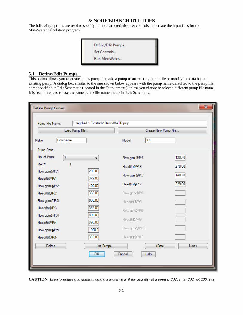
5: NODE/BRANCH UTILITIES The following options are used to specify pump characteristics, set controls and create the input files for the MineWater calculation program.
This option allows you to create a new pump file, add a pump to an existing pump file or modify the data for an existing pump. A dialog box similar to the one shown below appears with the pump name defaulted to the pump file name specified in Edit Schematic (located in the Output menu) unless you choose to select a different pump file name. It is recommended to use the same pump file name that is in Edit Schematic.
5.1 Define/Edit Pumps...
CAUTION: Enter pressure and quantity data accurately e.g. if the quantity at a point is 232, enter 232 not 230. Put

26
as many points on the pump curve as you can to help accuracy and convergence. Load Pump File: Click this button to edit an existing pump file. A standard AutoCAD file open dialog box will appear with the pattern extension .PMP. Browse your existing files for the pump file to edit. Create New Pump File: Click this button to create a new pump file. A standard AutoCAD file creation dialog box will appear with the pattern extension .PMP. Note: Each pump file can contain up to fifty (50) pumps. Pump Data: The options for creating and editing a pump follow: If you are creating a new pump file a blank screen will appear with the number of pairs defaulted to three. If you are editing an existing file, data for the first pump curve in the file will appear. Use the <Back and Next> options below to display the desired set of pump data. . Make: Enter a Make descriptor for the pump; up to 35 characters are allowed. The default name is Noname. It is recommended to keep the Make under 10 characters so that it shows up well under the Curve pop-down in Define and Modify branches. Model: Enter a Model descriptor for the pump; up to 35 characters are allowed. The default name is Noname. It is recommended to keep the Model under 10 characters so that it shows up well under the Curve pop-down in Define and Modify branches. No. Of Pairs: You must specify the number of pressure/quantity pairs you want to enter from the pump curve anywhere from 3 to10. After you enter the number of pairs, edit boxes for the unused pairs will be grayed out. Ref. #: This number is automatically assigned. It starts at 1 and increments from there each time you define a new pump. If you delete a pump, it sets all the pressures and quantities to zero and Make and Model to Undefined for that reference number but keeps the number in use. So you should always have sequential numbers in the pump file. It is better to change the information for a pump than to delete it. Flow gpm@ Px: Enter the pressure for point x. Enter the pressures sequential, beginning with the first or left most point of the pump curve. In imperial units the pressure is given in gallons per minute. Head (ft)@ Px: Enter the quantity for point x. Enter the quantities sequentially, beginning with the first or left most point of the pump curve. In imperial units the quantity is given in feet. Delete: Click this button to initialize the currently displayed pump description and curve data to defaults. Note that deleting pumps does not delete it from the branches that may be defined as pumps and use that curve. If a pump branch does use the curve that you deleted then it will give erroneous results. List Pumps: Click this option to display a list of the pumps in this file. This option brings up the same dialog box as does List Pumps in the Branch menu. <Back: Click this button to view or edit the information for the previous pump in the file. Next>: Click this button to view or edit the information for the next pump in the file. If you reach the last pump in the file, the following dialog box appears.

27
Click the Yes button to add another pump to the file. The above dialog box will appear without any data.
When you select this option a dialog box similar to the following appears. 5.2 Set Controls...
These are some simple controls that allow you to open and close the Named links based on triggers and conditions. Note: If you do not see any values in the Link pop-down, it is because it only list branches that have names. The same is true for the Node pop-down. Link: List of the links or branches that have names other than noname. Select the link that you want to open or close if some condition is met. Status: Open or close the link defined above when a condition is met. Trigger: The following options are currently allowed to trigger the operation:
If you select Clock Time or Run Time you can enter the time on the right edit box and AM or PM. If you select If Node then you can select the Node and whether it is above or below a certain number of feet to trigger the operation. Define New Control: After you select all the above information you can click this button to add the control to the list. Change/Update Control: If you need to make changes to a control that is already in the list, then highlight the line in the list make the changes and then click this button.

28
Delete Control: To delete a control from the list, highlight the line in the list and click this button to remove it from the list.
When you select this option a dialog box similar to the following appears. 5.3 Run MineWater...
Pump File Name to Use: The default pump file to use is the one that is set in Edit Schematic. You can select a different pump file by clicking the Browse Existing Pump Files button, but remember next time you Run Minewater again it will default back to what is set in Edit Schematic. So to be consistent, if there is a particular pump file that you will be using, it is best to set it in Edit Schematic.
Max. Iterations: The edit box to the right sets the maximum iterations to perform to get the network to converge.
Correction Factor: This is the tolerance level to check for. The lower the value the greater accuracy and lower the chance of convergence. Duration: The duration of the simulation. Use 0 to run a single period snapshot analysis. The default is 0. Hydraulic Timestep: Determines how often a new hydraulic state of the network is computed. If greater than either the Pattern or Report time step it will be automatically reduced. The default is 1 hour. Report Timestep: Sets the time interval between which output results are reported. The default is 1hour. Report Start: The length of time into the simulation at which output results begin to be reported. The default is 0. Start ClockTime: The time of day (e.g., 3:00 PM) at which the simulation begins. The default is 12:00 AM midnight. Use Controls: Check this box to use the controls defined in the Set Controls option.

29
Run MineWater: When you click this button the simulation runs and a dialog box similar to the following appears when the calculations are complete.
You can scroll down to see all the detailed results of the simulation. This dialog box has more information than any of the other functions. You can review it later by selecting Output and Review Network Messages.

30
6: OUTPUT MENU This menu provides options for displaying the results from running the MineWater program.
This option prints the quantities above the branches in the network and the node pressures above the nodes in the network. Since the quantity and pressure outputs are on a separate layer, you can turn them on or off as you want. The following figure is one section of a typical MineWater network with the pressures shown at the nodes and quantities on the branches.
6.1 Draw Quan/Pres Output...

31
This option brings up the following dialog box with a list of the pressures at each node organized by branch type. Select all branches or a specific type from the list box on the lower left.
6.2 List Pressure Output...
View Branch: To view a specific branch, highlight the branch in the list and then click the View Branch button to view the branch. The display will zoom in on the branch and a green arrow will point to the branch. As always, with the View Branch functions you have the option to zoom previous or stay zoomed in on the branch in question. Print List: This option allows you to print a list of all the branches in the list box. See the Print List option under List Branches for details of the printing option.
This option brings up the following dialog box with a list of the branches organized by branch type. Select all branches or a specific type from the list box on the lower left.
6.3 List Quantity Output...

32
View Branch: To view a specific branch, highlight the branch in the list and then click the View Branch button to view the branch. The display will zoom in on the branch and a green arrow will point to the branch. Print List: This option allows you to print a list of all the branches in the list box. See the Print List option under List Branches for details of the printing option.
This option reads from the output file and displays information about the last simulation run. This is the same information that is shown after you click the Run MineWater button.
6.4 Review Network Messages...

33
When you select this option you are given the chance to reverse branches that have a negative water flow. The following series of command prompts appear:
6.5 Reverse Selected Neg Branches
Create a four sided polygon which contains the branches to reverse: Pick Lower Left corner: Pick Upper Left corner: Pick Upper Right corner: Pick Lower Right corner: If there are branches in the selection set that have a negative quantity you will see a message similar to the following:
The command prompt will display the branch start node and end node that has been reversed similar to the following: Branch: noname from 3 to 1 has been reversed Branch: noname from 4 to 3 has been reversed If there are no negative quantity branches in the selection set you will see the following dialog box:
This option is identical to option 6.5 Reverse Selected Neg Branches except that it reverses all the negative quantity branches in the drawing and does not ask you to window around the ones you want to change.
6.6 Reverse All Negative Branches

34
When you select this option a dialog box similar to the following appears. You may want to use similar values as the ones shown below for your network.
6.7 Edit Schematic...
The Edit Schematic option is used to change the size of pressures, quantities, node numbers, names and arrows. It is also used to set the defaults names for the pump files and the PFG File (Branch code configuration files created from Configure Branches). The information is stored with the drawing so that you can have one pump file and one PFG file for several different scenarios. You can also change the position and orientation of the node numbers, pressures and quantities. If you want to change the size of the individual branch attribute blocks you can use the AutoCAD Scale command. Size of Node Numbers: This represents the size, in drawing units, of the node numbers. This value is used for existing nodes as well as upcoming nodes. Size of Nodes: This represents the size of the node circle. This value is used for existing nodes as well as upcoming nodes. Size of Pressures: This represents the size, in drawing units, of the pressures. This value is used for existing pressures as well as upcoming pressures. Size of Names: This represents the size, in drawing units, of the branch name and node name. This value is only used for existing branch and node names and does not apply to upcoming names, which will have a size of 1. Size of Quantities: This represents the size, in drawing units, of the branch quantities. This value is used for existing

35
quantities as well as upcoming quantities. Size of Arrows: This represents the size, in drawing units, of the arrows. This value is used for existing arrows as well as upcoming arrows. Move Attributes: This option automates the AutoCAD -Attedit command so that it defaults to moving text, one attribute at a time. You can move quantities, pressures, node numbers, or any other text that is associated with an attribute block. When you click this option, the following command line prompts appear. Select Attribute: After you select the attribute, the next prompt asks you to select the new location of the attribute. Enter insertion point: After you select the insertion point, the attribute will appear at the position you selected and the Edit Schematic dialog box reappears. Rotate Attribute: This option automates the AutoCAD -Attedit command rotate function. You can rotate quantities, pressures, node numbers, or any other text that is associated with an attribute block. When you click this button, the following command line prompts appear. Select Attribute: After you select the attribute, a construction line appears to indicate the orientation of the attribute. Orient the construction line to the desired angle and click the left mouse button. The attribute will now appear at the orientation you selected and the Edit Schematic dialog box reappears. Note: If you get an error saying that more than one brand is defined you should run the hidden MineWater command called PDELBRAN and then re-run Edit Schematic.

36
7: SYMBOLS The following menu appears when you select this pull down. The options allow you to annotate and modify the schematic drawing.
Select this menu if you wish to insert a title block in your drawing. After you select this option, you will see a set of cross hairs on the screen and will be prompted for the insertion point of the title block. Move the cross hairs to the point where you want the upper left corner of the title block and click the left mouse button. After you enter the insertion point of the title block, a series of seven prompts will request the scale, angle, drawing name, number, designer, location, scale, etc. For each prompt, you can either accept the default by pressing the ENTER key or type new information.
7.1 Title Block
The title block is inserted with the size specified for the x and y scale factors. This size may be completely out of proportion to the size of your drawing. It may be so small that you can hardly see it, or it may be so large that it overwrites much of your drawing. If it is the wrong size, you may scale it after it is inserted. The title block is a MineWater symbol which means that you may scale it, move it, etc. as a complete entity. If you need to change the block text you can use the AutoCAD ddatte command. You can use Edit Schematic to move or rotate the block attribute text if needed. You can also explode the block and then manually edit the text. However, after you have exploded the symbol, you can no longer treat it as a single entity.
Select this menu item if you wish to insert a North Arrow symbol in your drawing. When you have selected this menu, you will see a set of cross hairs on the screen and will be prompted for the insertion point of the North Arrow. Move the cross hairs to the point where you want the bottom of the North Arrow. Next you will be prompted for the scale and the rotation angle of the North Arrow. Enter the number of degrees of rotation to orient the arrow in the correct direction for your drawing. Zero degrees gives a vertical arrow. Positive degrees rotate the arrow counter-clockwise from the vertical, negative degrees rotate it clockwise. For example if the north direction of your map was directly toward the upper right corner, you could enter a rotation angle of either -45 or 315.
7.2 North Arrow
The North Arrow block is inserted with the size specified for the x and y scale factors. This size may be completely out of proportion to the your drawing. It may be so small that you can hardly see it, or it may be so large that it overwrites much of your drawing. If it is the wrong size, you may scale it after it is inserted. The north arrow is a MineWater symbol which means that you may scale it, move it, etc. as a complete entity. If you need to change the block text you can use the AutoCAD ddatte command. You can use Edit Schematic to move or rotate the block attribute text if needed. You can also explode the block and then manually edit the text. However, after you have exploded the symbol, you can no longer treat it as a single entity.

37
This option allows you to change the map scale symbol. You will be prompted for the X and Y axis scale factors and the angle through which to rotate the symbol. Next you enter the four dimensions of the scale legend. The dimensions are multiplied by the scale factors to create the symbol.
7.3 Scale Block
This option will prompt you for the location (center of pump symbol) and scale factor in the x and y direction of the pump symbol. Use the cursor to locate the symbol then enter the x and y scale factors and the rotation angle. The following is an example of a pump symbol.
7.4 Pump
This option will prompt you for the location (center of the valve open symbol) and scale factor in the x and y direction of the valve open symbol. Use the cursor to locate the symbol then enter the x and y scale factors and the rotation angle. The following is an example of a valve open symbol.
7.5 Valve-Open
This option will prompt you for the location (center of the valve closed symbol) and scale factor in the x and y direction of the valve closed symbol. Use the cursor to locate the symbol then enter the x and y scale factors and the rotation angle. The following is an example of a valve closed symbol.
7.6 Valve-Closed
This option will prompt you for the location (center of the check valve symbol) and scale factor in the x and y direction of the check valve symbol. Use the cursor to locate the symbol then enter the x and y scale factors and the rotation angle. The following is an example of a check valve symbol.
7.7 Check Valve