minevent module of i c a m p s software
TRANSCRIPT

MINEVENT
module
of
I C A M P S
software
Revision 08-29-2019
Version 5.0
Ohio Automation, Inc.
62971 Siverly Creek Road
McArthur, Ohio 45651
(740)596-1023
Copyright (c) 1987-2016 by Ohio Automation
All Rights Reserved.
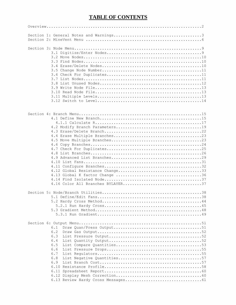
TABLE OF CONTENTS Overview...................................................................2
Section 1: General Notes and Warnings......................................3
Section 2: MineVent Menu ..................................................6
Section 3: Node Menu.......................................................9
3.1 Digitize/Enter Nodes.........................................9
3.2 Move Nodes...................................................10
3.3 Find Nodes...................................................10
3.4 Erase/Delete Nodes...........................................10
3.5 Change Node Number...........................................11
3.6 Check For Duplicates.........................................11
3.7 List Nodes...................................................11
3.8 List Unused Nodes............................................12
3.9 Write Node File..............................................13
3.10 Read Node File..............................................13
3.11 Multiple Levels.............................................13
3.12 Switch to Level.............................................14
Section 4: Branch Menu.....................................................15
4.1 Define New Branch............................................15
4.1.1 Calculate R..............................................17
4.2 Modify Branch Parameters.....................................19
4.3 Erase/Delete Branch..........................................22
4.4 Erase Multiple Branches......................................23
4.5 Move Multiple Branches.......................................23
4.6 Copy Branches................................................24
4.7 Check For Duplicates.........................................25
4.8 List Branches................................................26
4.9 Advanced List Branches.......................................29
4.10 List Fans...................................................31
4.11 Configure Branches..........................................32
4.12 Global Resistance Change....................................33
4.13 Global K factor Change .....................................36
4.14 Find Isolated Node..........................................37
4.16 Color All Branches BYLAYER..................................37
Section 5: Node/Branch Utilities...........................................38
5.1 Define/Edit Fans.............................................38
5.2 Hardy Cross Method...........................................44
5.2.1 Run Hardy Cross..........................................45
5.3 Gradient Method..............................................48
5.3.1 Run Gradient.............................................49
Section 6: Output Menu.....................................................51
6.1 Draw Quan/Press Output......................................51
6.2 Draw Gas Output.............................................52
6.3 List Pressure Output........................................52
6.4 List Quantity Output........................................52
6.5 List Compare Quantities.....................................53
6.6 List Pressure Drops.........................................55
6.7 List Regulators.............................................55
6.8 List Negative Quantities....................................57
6.9 List Branch Cost............................................57
6.10 Resistance Profile..........................................58
6.11 Spreadsheet Report..........................................60
6.12 Display Mesh Correction.....................................60
6.13 Review Hardy Cross Messages.................................61
1
6.14 Review Gradient Messages....................................61
6.15 Reverse Selected Neg Branches...............................61
6.16 Reverse All Negative Branches...............................62
6.17 Edit Schematic..............................................62
6.18 Color By....................................................64
6.19 Spanning Tree...............................................64
6.20 Twist Screen................................................65
Section 7: Symbols Menu....................................................66
7.1 Title Block.................................................66
7.2 North Arrow.................................................66
7.3 Fan.........................................................67
7.4 Regulator...................................................67
7.5 Stopping....................................................67
7.6 Door........................................................67
7.7 Drop Door...................................................67
7.8 Overcast....................................................67
7.9 Check.......................................................67
7.10 Scale Block.................................................67
7.11 Escapeways..................................................67
Section 8: Set Up Menu.....................................................68
8.1 Drawing Configuration........................................68
8.2 Export All Data..............................................70
8.3 Export Resistance Data.......................................70
8.4 Text Enlarge/Reduce..........................................70
8.5 Check Survey Data............................................70
8.6 Merge Networks...............................................71
8.7 Export General MineVent and Import General MineVent..........72
8.8 Import CONSOL Minimal comma separated data...................74
Index......................................................................75
2
OVERVIEW
MineVent runs within AutoCAD and has pull down menus, toolbars and most of the information can be entered with
the mouse or the digitizer puck. The preferred method for defining the ventilation network is to work from as-mined
and projections maps from your AutoCAD drawings. The nodes are picked up from the maps and because they are to
scale, the system can automatically compute the length of each branch. The network can also be digitized from a
hardcopy map of the mine, but the process is somewhat less convenient than working from the screen.
The following figure is a diagram of the initial STARTUP menu which appears whenever the ICAMPS shortcut is
executed. All the ICAMPS modules, e.g. MineSimUt, MineVent, MineVent 3D, MineWater and MineFire can be
accessed from this menu.
3
1. GENERAL NOTES AND WARNINGS
OSNAPS AND Z-VALUES
The osnap feature of AutoCAD can be used to select nodes, numbers and branches. If areas of the drawing are
cluttered the wrong entity may be selected. Use the osnap feature with caution. In a previous version of MineVent
selecting nodes with the osnaps ON caused errors in the node number being assigned the z-value. If you have
problems designating start and end nodes for a branch it could be that the node has the wrong z-value. The z-value of
the node should be the node number.
DIGITIZER
Working with a screen and mouse or a digitizing pad and puck are very similar operations. Both methods snap on to
points selected with the cursor and/or keyboard. If you make use of the AutoCAD digitizing template, data entry can
be limited to alphabetic information. See the AutoCAD instructions on setting up the digitizer template to match the
screen. If you have sufficient floor space, to position the digitizer tablet more or less horizontally, the screen and
keyboard can be placed on the tablet for easy viewing and access. Always check the screen to be sure that the proper
point or data has been entered.
NON-GRAPHICAL/INTERACTIVE METHODS
MineVent has provisions to accept data in free format tabular form. For example, you can key a list of nodes in free
format in the following sequence: node number, X coordinate, Y coordinate and use spaces to delineate each
parameter. The file created should have a file type of ".NOD". Use the Read Node File option in MineVent to read this
node file into your current drawing.
DELETING NODES AND BRANCHES
Never use the AutoCAD erase command to delete nodes and branches. Both are entities with associated attribute
blocks and the AutoCAD erase command does not recognize these associations. If you use the AutoCAD erase
command to delete a branch or node, you likely will be left with a corrupted drawing which is difficult to correct.
Specifically the nodes are stored in a file called node.dat stored in the drawing directory.
AVOID THE WBLOCK COMMAND
Never use the AutoCAD wblock command with MineVent drawings. Using this command to extract the branches
will cause the handles of the polylines to change and the program will no longer know which attribute block goes with
which polyline.
OPENING MORE THAN ONE DRAWING AND THE SDI VARIABLE
When working with MineVent drawings you can have more than one drawing open at a time. However, when any
ICAMPS shortcut is invoked it will set the Single Document Interface (SDI) variable to 1, which limits you to only
opening one drawing at a time. If you need to open more than one drawing you can type SDI at the AutoCAD
command prompt and set this variable back to 0. As long as the SDI variable is 0 or 1 the user can change it, but if it is
2 or 3 then that means that AutoCAD has determined that there are applications loaded that require only one document
to be opened. In most cases you can set the SDI variable to 0 and open more than one drawing while in MineVent .

4
AUTOCAD COMMAND ABBREVIATIONS IN MINEVENT
a draw arc by three points
aa edit attributes one at a time
ap edit attributes one at a time
av edit attributes one at a time
b break
c draw circle by two points or key-in diameter or radius
ch change
cf chamfer
cr color
cy copy
d dimension
DD edit definition block
dd edit definition block
ds distance between two points
er erase
ex extend
f draw fillet
h draw cross-hatch
i insert block
l draw line
la change layer settings
lf freeze layer
li line information
lo layer off
ls layer set
lt thaw layer
m move
m1 move to another layer
o offset
p draw polyline
pe polyline edit
r redraw
rg regenerate
rt rotate
CR change current layer color
s save
sc scale
t trim
tx insert text
vd delete view
vr restore view
vs ave view
za zoom all
zd zoom dynamic
ze zoom extents
zp zoom previous
zw zoom windows
5
MINEVENT MODEL BUILDING GUIDELINES
Regulators
The recommended procedure for modeling a regulator in an airway is to create a separate Regulator branch for the
regulator in series with the branch representing the airway. Assign the minimum allowable resistance to the branch
representing the regulator. When you run the MineVent program, it will limit the flow through this branch by
assigning a high resistance to this branch. Run the List Pressure Drops option to display the required resistance. You
will notice that most, if not all, branches will show a slight difference between the theoretical branch resistance (RR)
indicated by the branch flow quantity and pressure drop and the resistance (BR) based on the input data. These
differences are due to closure error in the calculations being limited by the Correction Factor. They usually have no
significant effect on the network flow analysis, and can be reduced by using a smaller Correction Factor. The trade off
is the number of iterations required for the network analysis to converge will increase, and some networks may not
converge if the Correction Factor is set too low.
Injecting Gas
Dummy branches are used to simulate gas entering the mine. These branches must begin at an atmospheric node and
you must specify the quantity of gas and the gas concentration expressed as a percentage. After you run the MineVent
program, use the Draw Gas Output option to display the quantity of gas flowing in the branches.
Natural Ventilation Pressure
Natural ventilation pressure (NVP) is frequently inserted at a branch that begins or ends at an atmospheric node, but
NVP can be inserted anywhere in the network by specifying a pressure when you define a branch. NVP usually is not
an important consideration and can be ignored. If it is ignored, and the model indicates that working face at
significantly different elevations are at approximately the same absolute pressure and they are connected via one or
more branches, NVP should be inserted in the ventilation network model. In such cases, including the NVP might
indicate a flow reversal at one of the faces. The pressure must be stated in inches of water gauge for the English units
version and pascals for the metric version. If the NVP assists the flow, it is positive and negative otherwise.
Currently, the Gradient Method does not support NVP, so if you need to use it you should only use the Hardy Cross.
Sizing Fans
Normally your network will contain one or more Fan Branches. If you do not have fan curve data, the fan branches can
be replaced with Fixed Quantity Branches. You can vary the quantity in such branches to determine the flow through
the fans that is required to achieved acceptable flow quantities through the mine. The pressure drop across these
Fixed Quantity Branches indicates where the fan must operate. This data can be compared to existing or proposed fans
to determine the required size and operating points for the fans.
Inputting Fan Data
Experienced ventilation engineers realize that ventilation survey data cannot be very precise, but small errors in
branch data do not significantly impact the analysis of a ventilation system. However, since all the air passes through
the fan branches, the fan curve data should be entered as accurately as possible. Do not round off the coordinates taken
from the fan curve, for example if the quantity coordinate is 232, use that number, not 230. This small difference can
result in a solution to the ventilation network analysis that is not on the fan curve. It also is a good practice to check
your fan curve input data by plotting the data points with graphing software such as a spreadsheet. The points should
be on a smooth curve. The MineVent program uses a mathematical function to convert the fan curve data to a sequence
of points that appear at the beginning of the DRAWING NAME.OUT file. Plot this data and look for any irregularities
in the curve. The fan data curve must be consistent without any abrupt variations in curvature or squiggles in the plot.
6
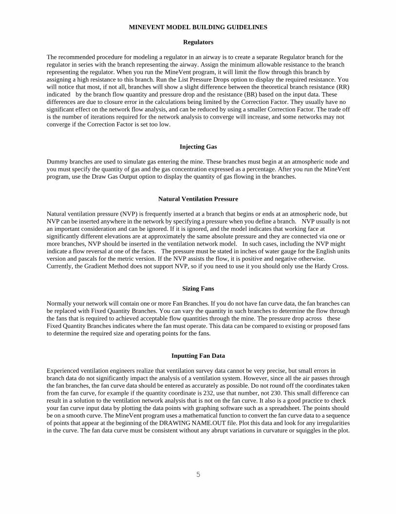
2. MINEVENT MENU MineVent has pull-down menus and icon toolbars as shown below. The first three headings on the left (Tools, Edit and
Display) contain some useful AutoCAD commands. The main MineVent features that are most commonly used are
the Node Menu, Branch Menu and Output Menu. The Symbols menu consist of annotation drawings such as fans,
regulators, title blocks etc.. The Setup menu contains options for changing drawing coordinates and other useful
utilities. The File Menu contains options for manipulating files and menus. All of these options will be discussed in
detail later.
The icons correspond to the following functions:
Insert Node | Define Branch | Modify Branch | Create Penn | Draw Q&P | List Pressure | List Quantity
List Pressure Drop | Color Branches by Q, Air Hp, Gas, Resistance, NVP or Pressure Drop
7
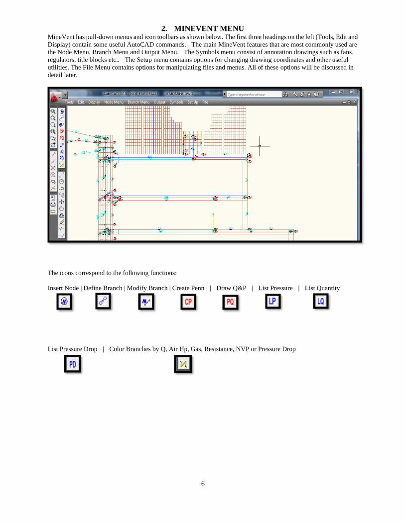
The contents of the first three Pull-Down commands follow:
2.1 Tools Menu
The Tools menu is mainly used for on-the-go osnapping. For example, if the osnaps are OFF and you want to
quickly snap to an intersection you can just go to Tools-->INTersec and then snap to the intersection then osnaps are
turned back off so that it is a quick one time use of osnaps. If you want to make osnaps "permanent" then select
OSNAP first and then the desired snap mode. For example if you are entering several nodes and need to snap to
intersections then select OSNAP first and the select INTersec. To turn osnaps back off then select OSNAP then
NONE.
The other useful features of the Tools menu is the Cancel command, Undo, Redo, and Redraw. A word of caution is
that you should be very careful using Undo and Redo in MineVent drawings. If you erase a node with the MineVent
Erase Node command and then do an undo you may end up with a node that is in the drawing but not in the node file
which can cause duplicate nodes and other issues. So it is highly advised that you do not use the Undo and Redo
unless you know that you are working on parts of the map that have no affect on MineVent entities such as nodes,
attribute blocks, branches and arrows.
2.2 Edit Menu
The Edit menu has several useful AutoCAD commands. As noted earlier you should be careful with the Erase
command as well as the copy command when working with MineVent entities. The rest of the commands here can be
used with relative safety. Of course you do not want to delete any of the MineVent layers such as Intake*, Faces,
Gobs, Return*, Leak*, or Vent* (where the * implies other letters and numbers). Also you should never Explode
any MineVent entities namely nodes or branches unless you know what you are doing and have a good reason to do so.
8
2.3 Display Menu
The Display menu has the most commonly used Zooming and Panning features of AutoCAD. As well as a menu
option called Drawing Aids which is essentially the AutoCAD Drafting options dialog box where you can change
grids, snap modes, polar tracking and more. The last option on this menu is called Modify Layer and can be used to
access the AutoCAD layer manager where you can turn on and off layers, freeze them, set the current layer, set layer
colors and other options depending on your version of AutoCAD.
9
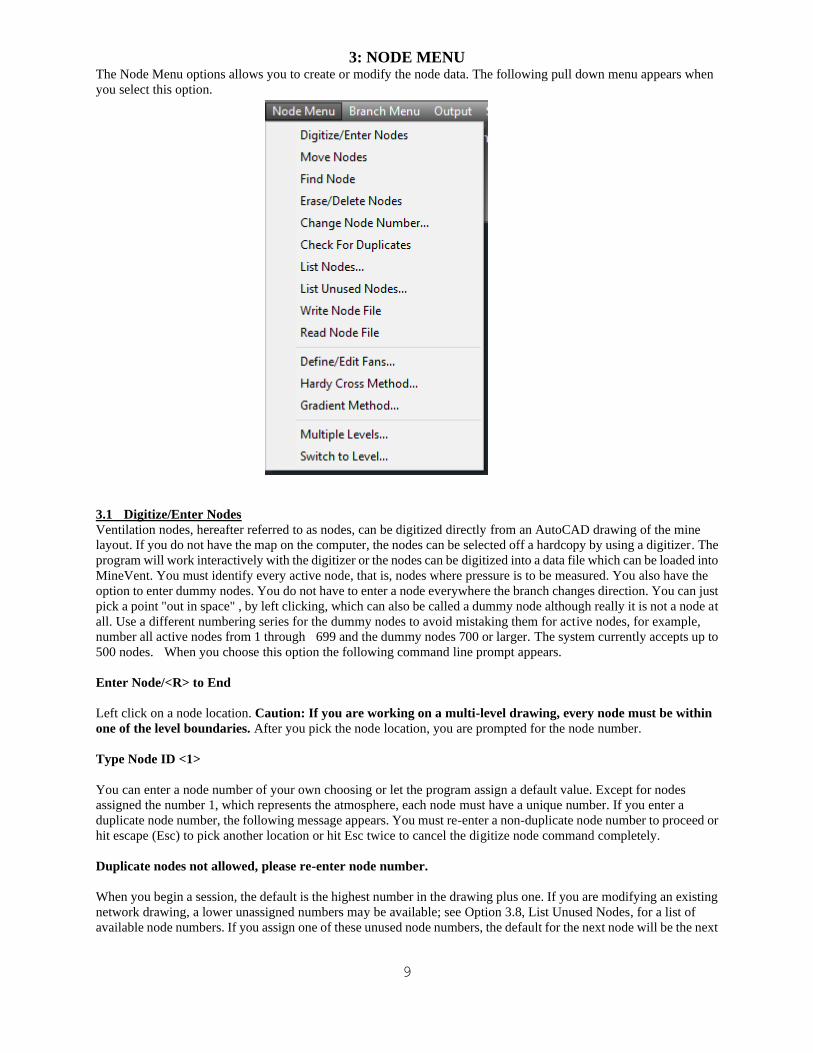
3: NODE MENU The Node Menu options allows you to create or modify the node data. The following pull down menu appears when
you select this option.
3.1 Digitize/Enter Nodes
Ventilation nodes, hereafter referred to as nodes, can be digitized directly from an AutoCAD drawing of the mine
layout. If you do not have the map on the computer, the nodes can be selected off a hardcopy by using a digitizer. The
program will work interactively with the digitizer or the nodes can be digitized into a data file which can be loaded into
MineVent. You must identify every active node, that is, nodes where pressure is to be measured. You also have the
option to enter dummy nodes. You do not have to enter a node everywhere the branch changes direction. You can just
pick a point "out in space" , by left clicking, which can also be called a dummy node although really it is not a node at
all. Use a different numbering series for the dummy nodes to avoid mistaking them for active nodes, for example,
number all active nodes from 1 through 699 and the dummy nodes 700 or larger. The system currently accepts up to
500 nodes. When you choose this option the following command line prompt appears.
Enter Node/<R> to End
Left click on a node location. Caution: If you are working on a multi-level drawing, every node must be within
one of the level boundaries. After you pick the node location, you are prompted for the node number.
Type Node ID <1>
You can enter a node number of your own choosing or let the program assign a default value. Except for nodes
assigned the number 1, which represents the atmosphere, each node must have a unique number. If you enter a
duplicate node number, the following message appears. You must re-enter a non-duplicate node number to proceed or
hit escape (Esc) to pick another location or hit Esc twice to cancel the digitize node command completely.
Duplicate nodes not allowed, please re-enter node number.
When you begin a session, the default is the highest number in the drawing plus one. If you are modifying an existing
network drawing, a lower unassigned numbers may be available; see Option 3.8, List Unused Nodes, for a list of
available node numbers. If you assign one of these unused node numbers, the default for the next node will be the next
10
higher unused node number. The system allows atmospheric nodes at multiple locations to eliminate the need for
connecting all the atmospheric airways to one point. You should assign number 1 only to the atmospheric node, since
this is the only number for which the automatic duplicate node checking is disabled. When entering Node # 1, you will
always get the following prompt:
Warning: Node # 1 is not checked for duplication
The system places the node number next to the node. The node can be re-positioned with the AutoCAD move
command and thereafter it will appear in the selected location. To move only the node number you can use
Output-->Edit Schematic and select the Move Attribute button and select the number (not the circle!).
NOTE: Frequently you want to see the coordinates of nodes as they are entered. If the coordinates are not displayed
(on the lower left of the screen in the status bar for most versions of AutoCAD) as you move the cursor, right click on
the coordinates in the status bar to turn on the Coordinates Display function.
3.2 Move Nodes
Use this option only to move nodes which are not connected to branches. If a branch is connected to the node, use
Option 4.4, Move Multiple Branches. Another alternative is to delete the branches which are connected to the node,
move it and then recreate the branches. When you select this option the following command line prompt appears:
Select objects:
Position the pick box on the circle, node number, or pressure value and click the left mouse key hit the enter key once
after selecting the node and drag the node to the desired position. You can actually move more than one node at a time
by picking several nodes at the Select objects prompt, but this is not recommended unless you are careful. Note: To
change the size of the pick box you can type pickbox at the AutoCAD command prompt.
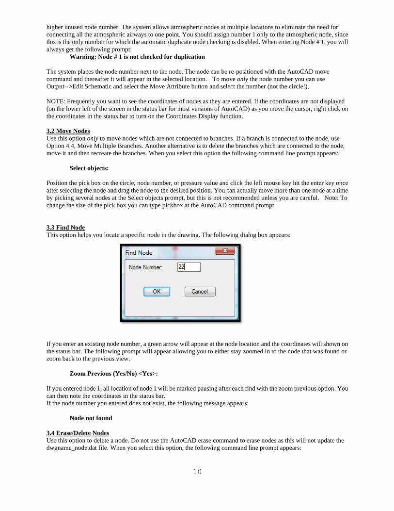
3.3 Find Node
This option helps you locate a specific node in the drawing. The following dialog box appears:
If you enter an existing node number, a green arrow will appear at the node location and the coordinates will shown on
the status bar. The following prompt will appear allowing you to either stay zoomed in to the node that was found or
zoom back to the previous view.
Zoom Previous (Yes/No) <Yes>:
If you entered node 1, all location of node 1 will be marked pausing after each find with the zoom previous option. You
can then note the coordinates in the status bar.
If the node number you entered does not exist, the following message appears:
Node not found
3.4 Erase/Delete Nodes
Use this option to delete a node. Do not use the AutoCAD erase command to erase nodes as this will not update the
dwgname_node.dat file. When you select this option, the following command line prompt appears:
11
Select objects:
Important: If you delete a node, any branch which depends on that node will not be deleted. You must also delete that
branch or the MineVent program may give you results that you do not expect as it only uses the data for the nodes that
are found in the branch blocks.
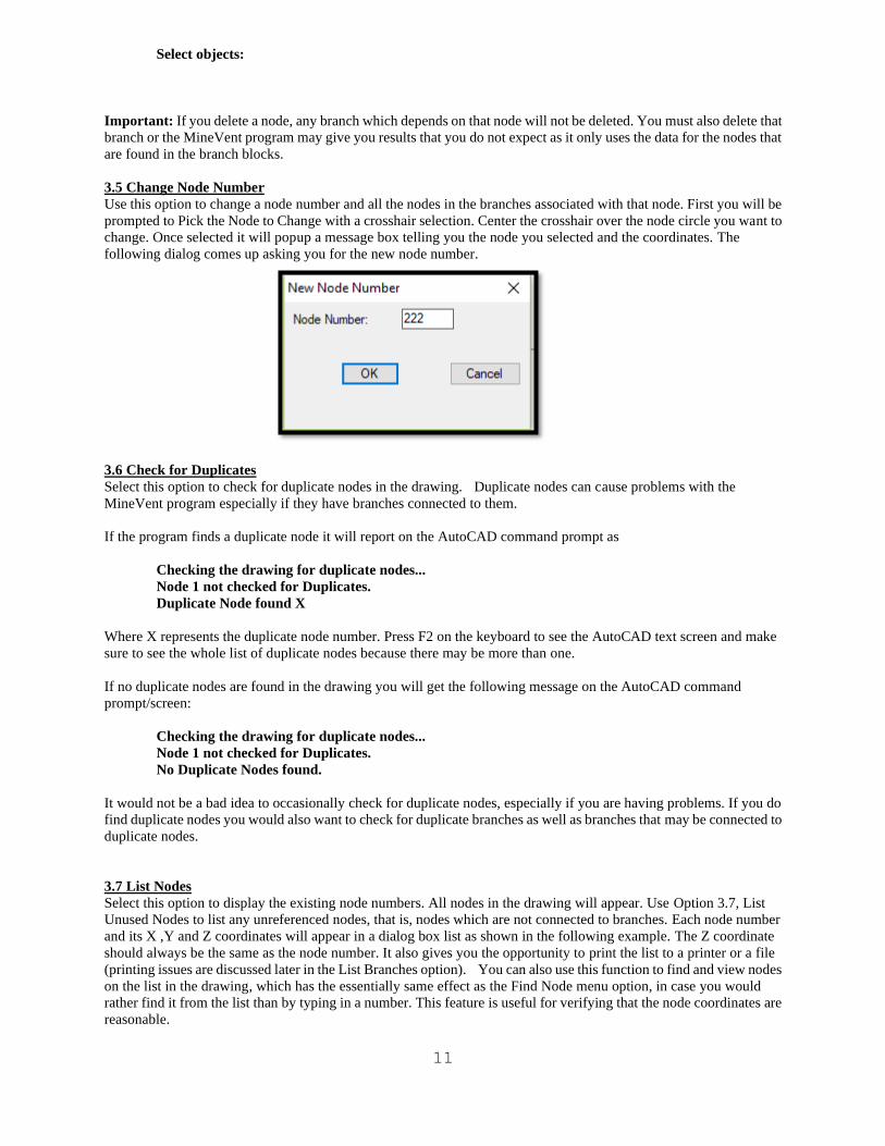
3.5 Change Node Number
Use this option to change a node number and all the nodes in the branches associated with that node. First you will be
prompted to Pick the Node to Change with a crosshair selection. Center the crosshair over the node circle you want to
change. Once selected it will popup a message box telling you the node you selected and the coordinates. The
following dialog comes up asking you for the new node number.
3.6 Check for Duplicates
Select this option to check for duplicate nodes in the drawing. Duplicate nodes can cause problems with the
MineVent program especially if they have branches connected to them.
If the program finds a duplicate node it will report on the AutoCAD command prompt as
Checking the drawing for duplicate nodes...
Node 1 not checked for Duplicates.
Duplicate Node found X
Where X represents the duplicate node number. Press F2 on the keyboard to see the AutoCAD text screen and make
sure to see the whole list of duplicate nodes because there may be more than one.
If no duplicate nodes are found in the drawing you will get the following message on the AutoCAD command
prompt/screen:
Checking the drawing for duplicate nodes...
Node 1 not checked for Duplicates.
No Duplicate Nodes found.
It would not be a bad idea to occasionally check for duplicate nodes, especially if you are having problems. If you do
find duplicate nodes you would also want to check for duplicate branches as well as branches that may be connected to
duplicate nodes.
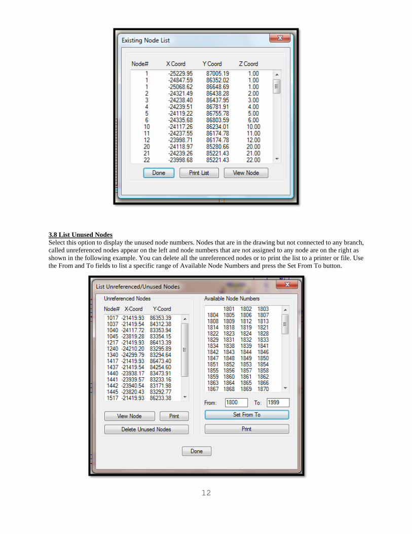
3.7 List Nodes
Select this option to display the existing node numbers. All nodes in the drawing will appear. Use Option 3.7, List
Unused Nodes to list any unreferenced nodes, that is, nodes which are not connected to branches. Each node number
and its X ,Y and Z coordinates will appear in a dialog box list as shown in the following example. The Z coordinate
should always be the same as the node number. It also gives you the opportunity to print the list to a printer or a file
(printing issues are discussed later in the List Branches option). You can also use this function to find and view nodes
on the list in the drawing, which has the essentially same effect as the Find Node menu option, in case you would
rather find it from the list than by typing in a number. This feature is useful for verifying that the node coordinates are
reasonable.
12
3.8 List Unused Nodes
Select this option to display the unused node numbers. Nodes that are in the drawing but not connected to any branch,
called unreferenced nodes appear on the left and node numbers that are not assigned to any node are on the right as
shown in the following example. You can delete all the unreferenced nodes or to print the list to a printer or file. Use
the From and To fields to list a specific range of Available Node Numbers and press the Set From To button.
13
3.9 Write Node File
This option is very useful when the node data need extensive editing. The following command line prompt appears
when you select this option:
Enter Node data file to Write <DWGNAME.NOD>
The program will create a new file designated as <DWGNAME>.NOD where <DWGNAME> is the name of the
drawing file you are currently working on. It is recommended that you enter a name that you know exactly where it is
and the name of the file. This new file can be edited with a full screen editor. After the <DWGNAME>.NOD file is
corrected it can replace the original data using Option 4.7, Read Node File. This option will write all the occurrences
of Node # 1 into the node file.
3.10 Read Node File
This option is used to load nodes into the drawing from <DWGNAME>.NOD file. Nodes already in the drawing
will be flagged as duplicates and skipped. The following command line prompt appears when you select this option:
Enter the Node File Name:>
The input file can be in free format but the data must be in the following sequence node number, X coordinate, Y
coordinate. The list of nodes is checked for duplicate node numbers as they are read. Whenever the system reads
Node #1, it will display the following prompt:
Node # 1 not checked for duplication
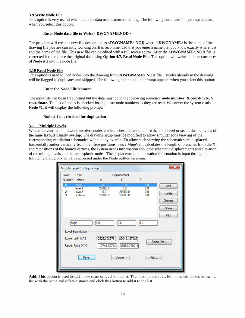
3.11 Multiple Levels
Where the ventilation network involves nodes and branches that are on more than one level or seam, the plan view of
the mine layouts usually overlap. The drawing setup must be modified to allow simultaneous viewing of the
corresponding ventilation schematics without any overlap. To allow such viewing the schematics are displaced
horizontally and/or vertically from their true positions. Since MineVent calculates the length of branches from the X
and Y positions of the branch vertices, the system needs information about the schematic displacements and elevation
of the mining levels and the atmospheric nodes. The displacement and elevation information is input through the
following dialog box which is accessed under the Node pull-down menu.
Add: This option is used to add a new seam or level to the list. The maximum is four. Fill in the edit boxes below the
list with the name and offset distance and click this button to add it to the list.

14
Delete: This option is used to delete a level from the list.
Change: This option is used to change the information about a level in the list. Fill in the edit boxes below the list with
the name and offset distance and click this button to change it in the list.
Show: This option is used to display the selected level enclosed by a green box.
Print: This option is used to print the level information in the list to a printer or a file. Printing issues are discussed
later in the List Branches option.
Select Pts. This option is used to select the Level Boundaries for the origin level. The boundaries for all other levels
will be calculated from the origin level boundaries and the displacement coordinates.
The system allows for four levels, one of which is the ground surface. The drawing is divided into four quadrants
which are referred to as levels numbered from 0 to 3 in the dialog box. Level 0 is located in the lower left quadrant of
the drawing, Level 1 is on the lower right and Level 2 is on the upper left. Level 3 is reserved for the ground surface
terrain model and placed in the upper right quadrant. Normally Level 0 would correspond to the top most mine level.
The next level would be to its right, and the lowest mine level is drawn in the upper left quadrant.
The level names can be specified by the user. In the above example, the levels have been arbitrarily assigned the names
origin for level 0, level1for level 1, level2 for level 2 and surface for level 3.
You must also specify the X (horizontal) distance that the drawings on level 1 and 3 have been displaced from their
original positions. Likewise you must specify the Y (vertical) distance the drawings on level 2 and 3 have been
displaced vertically. The elevation values are the average elevation of each of the mining levels and a default value for
the ground surface elevation. You must also provide the lower left and upper right boundaries for the drawing at Level
0. You can do this by using the Select Pts button, windowing around the area that you want to designate as the level 0
dimensions or boundaries and then hitting the Change button to save the values. Note: You must hit the Change
button after selecting the origin boundary points, otherwise the information is not updated. The system adds the
displacements to the Level 0 boundaries to determine the boundaries of the other levels. After you enter the above
data, click the OK button to save the data.
You define branches by picking points on the drawing that correspond to the actual airway path and a branch may have
many vertices between the beginning and ending nodes. However, all nodes, numbered or where airways change
direction, must be within one of the level boundaries.
The system calculates the branch lengths by using the above information and the X,Y coordinates from the drawing.
The Z coordinate of the atmospheric nodes will be computed from the surface contours on a ground terrain drawing in
the level 3 quadrant. This must be on a layer called VCONTOUR. You must use the AutoCAD XREF command to
insert the terrain drawing into your schematic drawing. See the end of section 7 for instruction on using that
command. If no terrain drawing is provided, the Z coordinate of the atmospheric nodes defaults to the elevation given
for the Level 3 quadrant. You can always over ride the map or default value.
3.12 Switch to Level
This option lets you move the schematic for a level to the center of the screen. When the schematic requires multiple
levels the drawing can become very large and viewing all levels simultaneously often is not practical. When you select
this option, the following dialog box appears.
15
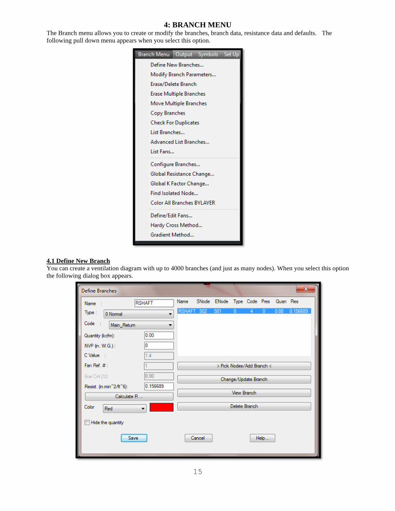
4: BRANCH MENU The Branch menu allows you to create or modify the branches, branch data, resistance data and defaults. The
following pull down menu appears when you select this option.
4.1 Define New Branch
You can create a ventilation diagram with up to 4000 branches (and just as many nodes). When you select this option
the following dialog box appears.
16
You can create new branches as well as modify any of the branches you have created within the same Define New
Branch session.
To create a branch, fill in the edit boxes on the left. The branch name is limited to 25 lower case or 19 upper case
characters. The branch type names indicate their application, except that dummy branches are used to inject gas into
the system. After you select the branch type and code, data can be entered for the relevant parameters. Take the zero
default for quantity except for fixed and limited quantity and dummy branches. For most applications the natural
ventilation pressure can be ignored; if otherwise, input the natural pressure. Enter the resistance if known, otherwise
use Calculate R. However, the calculation resistance function will not execute until the airway path has been
specified. Click the Pick Nodes/Add Branch button to select the nodes for the branch.
Name: The name can be twenty five characters long but only 19 lower case and 15 upper case characters will be
displayed.
Type: Select the branch type from the drop down list.
Note: If you select the Regulator branch type then the labels for the dialog edit boxes changes from C Value to Height
Max and from Fan Ref to Width Max which are used in the regulator resistance calculation.
Code: Select the code from the drop down list. Code names and associated default information, line type and color
information can be set using Configure Branches.
Quantity: The quantity flowing in the branch must be specified for Fixed and Limited Quantity type branches. A
quantity must also be specified for Dummy branches which represent gas injected into the mine from the atmosphere
(Node 1) to a non-atmospheric node. The Gas Concentration (Gas Cnt.) must also be specified for such branches.
Quantities may be specified for other branch types but are only used as starting values in iterative calculation
procedure.
NVP:This parameter is used to represent Natural Ventilation Pressure (NVP). Frequently these branches will start or
end at an atmospheric node, but any branch in the network can have NVP. The units are inches of water gauge in the
english version and pascals in the metric version.
C Value: This parameter is the exponent of the quantity factor in the resistance equation for leakage branches. The
coefficient of the pressure variable is assumed to be one.
Fan Ref: This number applies to fan branches and corresponds to the a fan curve in the .FAN file which you specify
for this application. The number here should match the fan reference number of the fan curve you want to use.
Gas Cnt.: The gas concentration for gas injection with Dummy branches.
Resist: You can specify the branch resistance but in most cases you will use the Calculate R function to compute the
branch resistance from the 9 available formulas. Note that the Non Equal Branches in series formula has been
disabled.
>Pick Nodes/Add Branch<: When you click this button, the following command line prompts appear.
Pick Start Node/<R> to end
You must have previously defined the start node. If you cannot find the desired node, use the Find Node
option to locate the node. After you pick the start node, the command line prompt changes to the following.
Pick [End Node/Dummy Node]/<R> to end
The branch must end at a node you previously defined, but the line representing the branch can follow the
actual air flow path. Pick the points (called dummy points) where the airway changes direction in the order
in which they will be connected.. After you pick a point, the node number (0 for dummy points) and its
coordinates appear in the command line after the prompt. After you pick each point, the above prompt
reappears and a line will be drawn between the points you pick.

17
CAUTION: If you are working with a multi-level drawing, all intermediate nodes and vertices where the
airways change direction, must be within one of the level boundaries.
The End node must be one of the active nodes you previously defined. After you pick the End node press the
Enter key to indicate the end of the branch.
Note: If you are defining several branches you may want to set up AutoCAD to associate the right mouse
button with the Enter key. This will save you time from constantly having to hit Enter on the keyboard and
you can define all your branches just using the mouse. To set this type config at the AutoCAD command
prompt select the User Preferences tab, click the Right Click Customization button and then select the Turn
on Time Sensitive Right Click checkbox. This may vary on different versions of AutoCAD or it may
already be set.
When you indicate the End node has been picked, the new branch will appear highlighted at the bottom of
the list. If you indicate the true airway path, the length of the airway can be calculated and used in the
resistance calculation. If you did not enter the branch resistance, the resistance will be a default value. Use
the Calculate R option to calculate the resistance and it will update the resistance in the listing.
Calculate R: When you click the Calculate R button, the following dialog box appears.
This option uses formulas to determine the resistance. Select a formula that is appropriate for the branch type/code
combination being defined. After you select a formula, only the applicable parameters in the box will be highlighted.
For a new branch the parameters contain the code defaults as indicated by the Code button under Defaults By option
and the message "Branch CODE DEFAULTS shown" appears at the bottom of the dialog box. The parameter values
correspond to the code default values you entered in the Configure Branches option. If you are computing the branch
length from survey data, the branch length is not used in the calculation.
If you edit a previously defined branch, the Default By: option changes to Previous. You can change any of the
highlighted parameter values. The branch length is automatically calculated from the branch polyline, but you have
the option to change the length if necessary. The message at the bottom of the dialog box changes to "Previous
resistance defaults shown: Branch Length = Previous Length".
The PresQuan and SURVEYED formulas apply if you know the pressure and quantity in a branch. After you have
done a ventilation survey, you can enter the survey data one branch at a time using PresQuan or you can use the
18
SURVEYED formula with existing files or create files of the surveyed pressures and quantities. The pressure data is
stored in a file you designate as <DWGNAME.P> which has the format (node number, pressure) and the quantities are
stored in a file <DWGNAME.Q> which has the format (start node number, end node number, quantity).The
program searches the .Q file for the node combination which matches the branch you are entering. If the branch is in
the .Q file, the program then looks for the surveyed node pressures in the .P file and computes the branch resistance.
The formula NE B-S: n None Equal Branches in Series has been disable because such branches are difficult to modify.
If you have a situation where non-equal entries are in series, create a separate branch for each segment in the series.
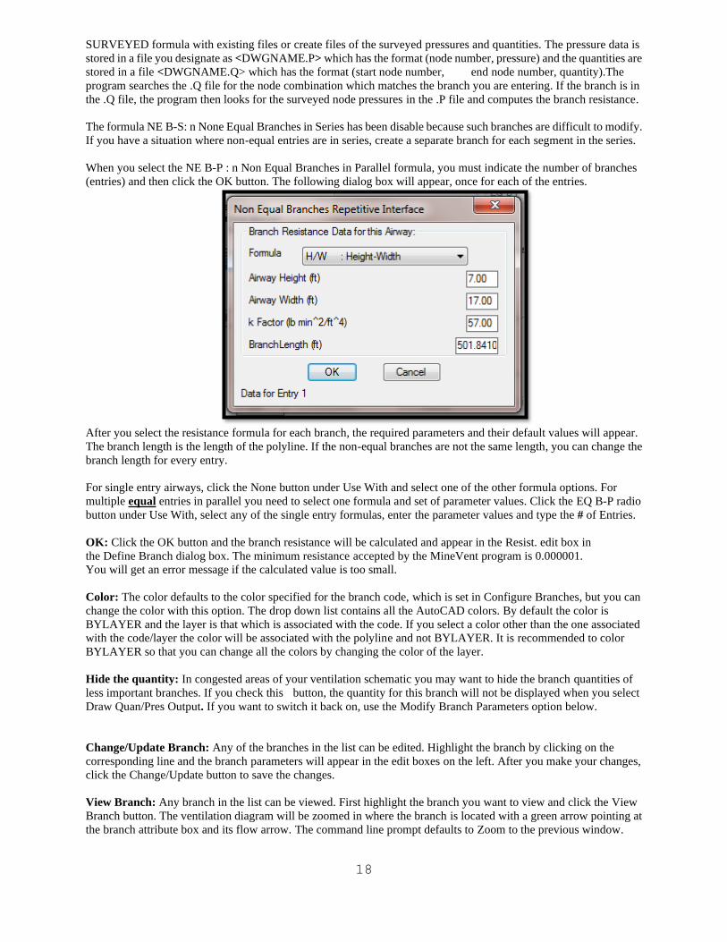
When you select the NE B-P : n Non Equal Branches in Parallel formula, you must indicate the number of branches
(entries) and then click the OK button. The following dialog box will appear, once for each of the entries.
After you select the resistance formula for each branch, the required parameters and their default values will appear.
The branch length is the length of the polyline. If the non-equal branches are not the same length, you can change the
branch length for every entry.
For single entry airways, click the None button under Use With and select one of the other formula options. For
multiple equal entries in parallel you need to select one formula and set of parameter values. Click the EQ B-P radio
button under Use With, select any of the single entry formulas, enter the parameter values and type the # of Entries.
OK: Click the OK button and the branch resistance will be calculated and appear in the Resist. edit box in
the Define Branch dialog box. The minimum resistance accepted by the MineVent program is 0.000001.
You will get an error message if the calculated value is too small.
Color: The color defaults to the color specified for the branch code, which is set in Configure Branches, but you can
change the color with this option. The drop down list contains all the AutoCAD colors. By default the color is
BYLAYER and the layer is that which is associated with the code. If you select a color other than the one associated
with the code/layer the color will be associated with the polyline and not BYLAYER. It is recommended to color
BYLAYER so that you can change all the colors by changing the color of the layer.
Hide the quantity: In congested areas of your ventilation schematic you may want to hide the branch quantities of
less important branches. If you check this button, the quantity for this branch will not be displayed when you select
Draw Quan/Pres Output. If you want to switch it back on, use the Modify Branch Parameters option below.
Change/Update Branch: Any of the branches in the list can be edited. Highlight the branch by clicking on the
corresponding line and the branch parameters will appear in the edit boxes on the left. After you make your changes,
click the Change/Update button to save the changes.
View Branch: Any branch in the list can be viewed. First highlight the branch you want to view and click the View
Branch button. The ventilation diagram will be zoomed in where the branch is located with a green arrow pointing at
the branch attribute box and its flow arrow. The command line prompt defaults to Zoom to the previous window.
19
Delete: Any branch in the list can be deleted. First highlight the branch you want to delete and click the Delete Branch
button. The corresponding branch will be deleted from the network.
OK: Click OK to save all the branches in the list and make them a part of the ventilation network. You can erase them
later if you need to.
Cancel: Click Cancel to remove all the branches in the list, that were defined in the current Define New Branch
session, from the ventilation network.
CAUTION: Hitting cancel will delete all the branches that you have defined in the current Define New Branches
session. You will not be ask if you are sure that you want to delete.
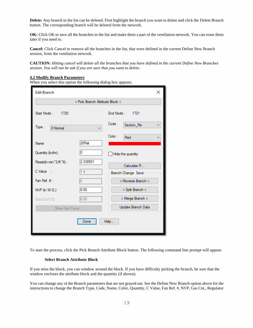
4.2 Modify Branch Parameters
When you select this option the following dialog box appears.
To start the process, click the Pick Branch Attribute Block button. The following command line prompt will appear:
Select Branch Attribute Block
If you miss the block, you can window around the block. If you have difficulty picking the branch, be sure that the
window encloses the attribute block and the quantity (if shown).
You can change any of the Branch parameters that are not grayed out. See the Define New Branch option above for the
instructions to change the Branch Type, Code, Name, Color, Quantity, C Value, Fan Ref. #, NVP, Gas Cnt., Regulator
20
Height and Width, Hide the quantity and Calculate R options. The other buttons provide the following options:
Reverse Branch: Use this option to reverse the direction of the arrow and interchange the start and end nodes for a
single branch. If you have run the MineVent program and want to reverse the flow direction for branches with negative
flow, use List Negative Quantities, Reverse Selected Neg Branches or Reverse All Negative Branches from the Output
menu.
Split Branch: This option allows you to insert a node into an existing branch. The two resulting branches will be of
the same type and code as the original branch. You have the option to allow the program to assign automatically the
resulting branch resistances in proportion to their lengths.
CAUTION: The system will not allow you to split a fixed or limited quantity branch because the MineVent program
does not allow two fixed or limited quantity branches in series. Change the branch type before proceeding.
When you select this option, the following command line prompts appear:
Updating Branch Data...
Select split point for branch polyline (Snap Mode Required)
Normally the required snap node is NEArest. After you select the split point the prompt is:
Node Number for split point <number>:
The default number is always one greater than the largest node number in the drawing. You can specify any unused
node number. The next prompt is:
Update the resistance for the new branches (Yes/No) <Yes>:
If your schematic is drawn to scale, take the default and the resistance of the original branch will be allocated to the
new branches in proportion to their lengths. If your schematic is not to scale, enter No and you will be prompted for
each resistance as follows:
Resistance from Start node to split
and
Resistance from split to end node
After the resistance is entered, either automatically or manually, the next prompt gives you the option to redraw the
schematic
Redraw Updated drawing (yes/No) <N>:
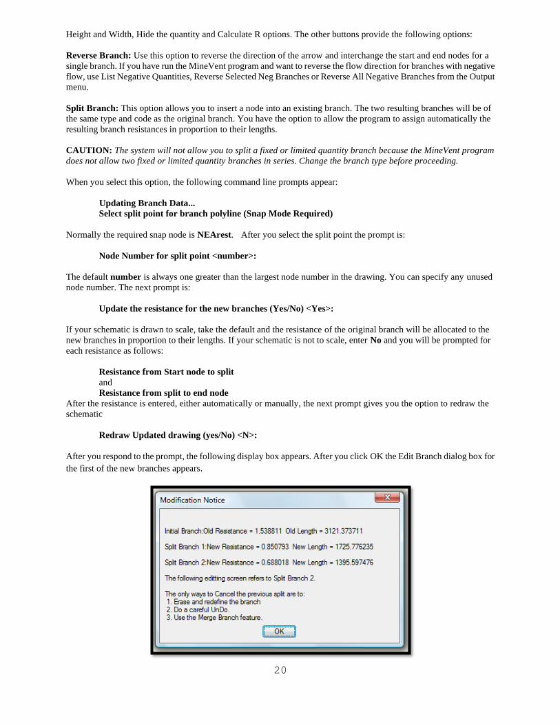
After you respond to the prompt, the following display box appears. After you click OK the Edit Branch dialog box for
the first of the new branches appears.
21
Merge Branch: This option allows you to combine two branches that are in series by removing their connecting node.
Since more than two branches could be in series, the command line asks you to pick the attribute block for the second
branch. If the branches are not of the same type, the resulting branch will be of the type and code of the first branch
that was picked. The resistance of the new branch will be the sum of their separate resistances.
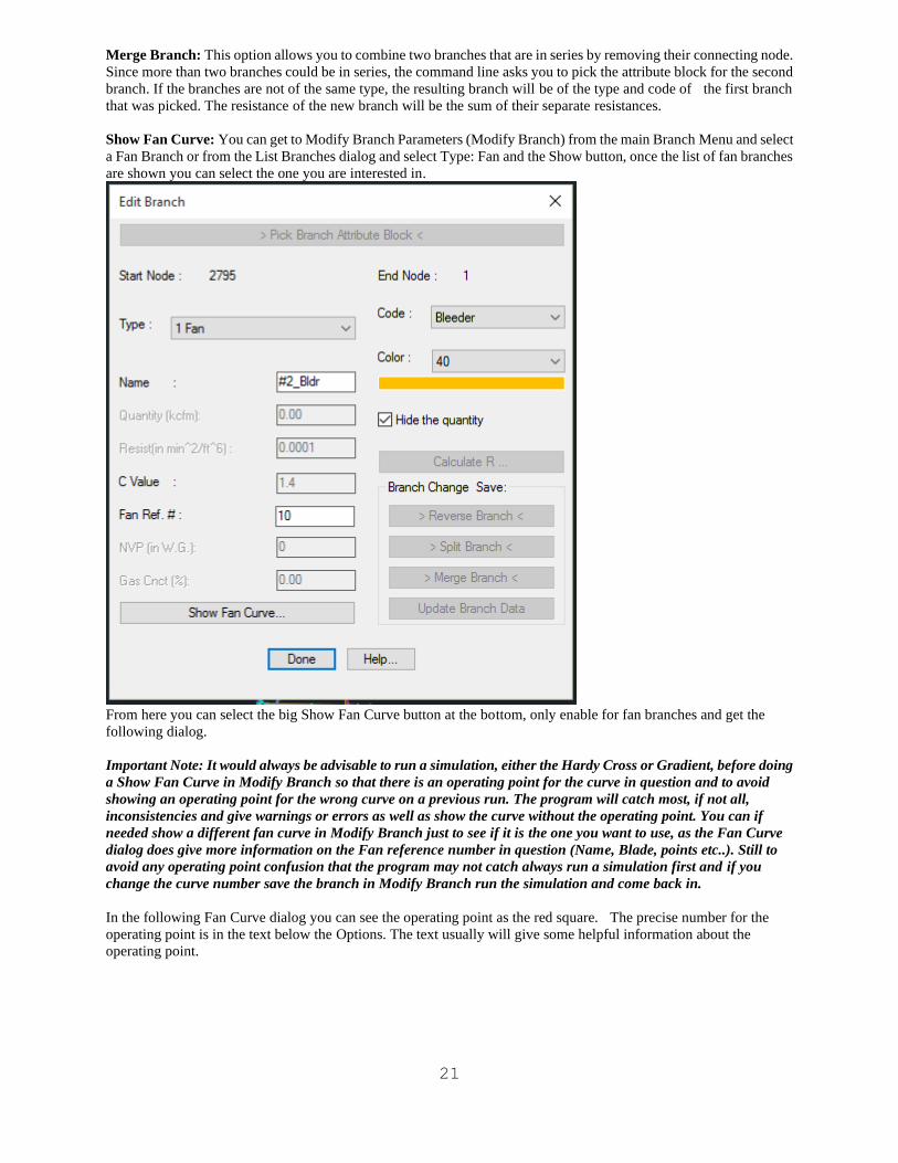
Show Fan Curve: You can get to Modify Branch Parameters (Modify Branch) from the main Branch Menu and select
a Fan Branch or from the List Branches dialog and select Type: Fan and the Show button, once the list of fan branches
are shown you can select the one you are interested in.
From here you can select the big Show Fan Curve button at the bottom, only enable for fan branches and get the
following dialog.
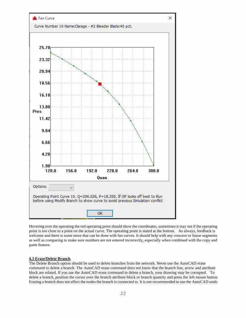
Important Note: It would always be advisable to run a simulation, either the Hardy Cross or Gradient, before doing
a Show Fan Curve in Modify Branch so that there is an operating point for the curve in question and to avoid
showing an operating point for the wrong curve on a previous run. The program will catch most, if not all,
inconsistencies and give warnings or errors as well as show the curve without the operating point. You can if
needed show a different fan curve in Modify Branch just to see if it is the one you want to use, as the Fan Curve
dialog does give more information on the Fan reference number in question (Name, Blade, points etc..). Still to
avoid any operating point confusion that the program may not catch always run a simulation first and if you
change the curve number save the branch in Modify Branch run the simulation and come back in.
In the following Fan Curve dialog you can see the operating point as the red square. The precise number for the
operating point is in the text below the Options. The text usually will give some helpful information about the
operating point.
22
Hovering over the operating the red operating point should show the coordinates, sometimes it may not if the operating
point is too close to a point on the actual curve. The operating point is stated at the bottom. As always, feedback is
welcome and there is some more that can be done with fan curves. It should help with any concave or linear segments
as well as comparing to make sure numbers are not entered incorrectly, especially when combined with the copy and
paste feature.
4.3 Erase/Delete Branch
The Delete Branch option should be used to delete branches from the network. Never use the AutoCAD erase
command to delete a branch. The AutoCAD erase command does not know that the branch line, arrow and attribute
block are related. If you use the AutoCAD erase command to delete a branch, your drawing may be corrupted. To
delete a branch, position the cursor over the branch attribute block or branch quantity and press the left mouse button
Erasing a branch does not affect the nodes the branch is connected to. It is not recommended to use the AutoCAD undo
23
command to undo a deleted branch, but if absolutely necessary make sure to undo the polyline, arrow, attribute block
and check the branch using the ddatte and list AutoCAD commands to make sure that the handles are correct.
4.4 Erase Multiple Branches
The Erase Multiple Branches option should be used to delete a group of branches from the network. Never use the
AutoCAD erase command to delete branches. The AutoCAD erase command does not know that the branch line,
arrow and attribute block are related. If you use the AutoCAD erase command to delete a branch, your drawing may be
corrupted. To delete a group of branches, create a closed polygon around the branch attribute blocks you want to erase.
The following prompts show on the command line.
Create closed polygon: Pick Start Point:
Pick Next Point/<RETURN> to Close:
Pick Next Point/<RETURN> to Close:
Pick Next Point/<RETURN> to Close:
Pick Next Point/<RETURN> to Close:
Erasing branches does not affect the nodes the branches are connected to. It is not recommended to use the AutoCAD
undo command to undo an Erase Multiple Branch.
4.5 Move Multiple Branches
This option allows you to modify a network where the change involves moving a group of branches such as
lengthening or shortening mains or a longwall panel. When you select this option, the command line will ask you to
create a closed polygon around the branches to be moved and then to drag the selected branches (making the main or
panel longer or shorter). The coordinates of the moved nodes will be updated and the following command line prompt
will appear.
Update the resistance for the new branches (Yes/No) <Yes>
If you hit <Enter> or type Yes to the above prompt then the following dialog box will appear allowing you some
interaction for the proposed branch length/resistance changes.
24
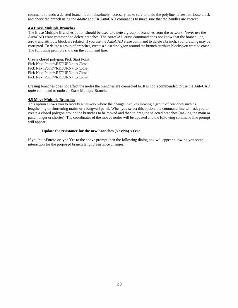
The main areas to pay attention to in the above dialog box is the Resistance Formula, the Old-R(branch resistance
before the stretch) and the New-R (branch resistance that will be assigned when you hit Done).
By default the branches that have a resistance formula that uses the length will have a check in the "Update the Branch
Length and Resistance for this Branch" checkbox and the resistance formulas that do not use a length will not be
checked. So that for each branch in the list you can check or uncheck the checkbox and watch the New-R change
accordingly. If you have a branch that does not use the length in the calculations, such as STOP-R for leakage
branches, then you can edit them individually from the list by selecting the branch in the list and hitting the Edit
button.
CAUTION: The objects inside the window move without changing their shape or position relative to other objects
within the window but objects outside the window on branches cut by the window are repositioned in proportion to the
distance the window is moved. Use the following precautions:
1. If you are shortening branches, be careful not to window the arrow and block on any branch that will be shortened
or else they may overlay other branches of the network.
2. Node entities include the circle, node number and pressure. Likewise branch includes the attribute block, arrow and
quantity. If you are moving nodes or branches, be sure that the window encloses both the entity and all of its
associated objects.
4.6 Copy Branches
This option allows you to edit a ventilation schematic by copying a section of the an existing ventilation schematic
diagram. You select the nodes and branches to copy by drawing a multi-sided closed polygon window around the
nodes and branches to be copied. All the nodes inside the window and the branches which connect them are copied.
Since the system does not allow duplicate node numbers, your must specify the node number as it is copied. The
default is the next number that is higher than the largest number on the drawing, but you can specify any unused
number. The system also asks for the new name of the branch as it is copied. All the other parameters are assumed to
25
be the same as the original values including resistance formulas and resistance data.
When you select this option, the following command line prompts appear.
Create Closed Polygon: Pick Start Point
After you select a point, the following command line prompt reappears after each selection. The polygon can have any
size or shape.
Pick Next Point / <Return> to Close
After you close the polygon, the prompt becomes
Specify base point
After you select the base point, the prompt asks for the point where the base point will be moved.
Specify second point
You can pick a point with the cursor or use the command line to specify a distance and angle or the coordinates of the
point. After you specify the point, the nodes are moved, one at a time. The command line will show which node is
being moved. Since all but the atmospheric nodes numbers must be unique, you will be asked for the new node
number. The prompts are:
Copying Node # X
Node Number for New Node <Y>:
where X is the existing node number and Y is the default node number. The default is the next number higher than the
largest node number on the drawing. You can specify any unused number. If you enter a lower number, the next
default will be the first available node number larger than the number you specified If you entered a duplicate node
number, the following prompt appears and you must enter a unique number.
Duplicate Nodes not allowed, please re-enter node number.
Node Number for New Node <Y>:
The copying prompts repeat until all the nodes within the window have been moved. Then the branches connected to
the are copied. You are asked to specify names for the copied branches but all other information is automatically
transferred. Branch names do not have to be unique, but unique names are helpful when evaluating ventilation
networks.
4.7 Check for Duplicates
This option gives you the opportunity to check the entire drawing for multiple branches between the same two nodes.
CAUTION: This option must search the entire drawing and may take several minutes to complete for a large
drawing.
You can intentionally define multiple branches between two nodes, but the better approach is to use multiple branches
in parallel option. The MineVent program has difficulty with multiple branches between nodes. Sometimes the
problem will not run and if it does run, the calculated flow quantities may be assigned to the wrong branch. In the
MineVent program and in the Draw Quantity and Pressure function branches are identified by their starting and ending
nodes which should be unique. Otherwise the program does not know which branch to put the quantity on.
26
4.8 List Branches...
The list of branches appear in a dialog box as shown in the following example. Each of the option buttons is described
below.
Showing Specific Branches: To view only branches of a certain type, code, resistance formula, and/or k factor you
can select your search criteria from the pop down menus and then hit the Show button to see them in the list. The
different search filters are listed and discussed below.
Type: You can list all the branches or only those for a specific branch type. The list defaults to all types. To select a
specific type, click the drop down list to the right of the word Type to display the available branch types as shown
below and then pick the desired type and then hit the Show button.
Code: You can list only those branches for a specific branch code. The list defaults to all codes. To see the branches
that contain a specific code, click the drop down list next to the word Code as shown below and then pick the desired
code and then hit the Show button. This drop down list the descriptions for the code defined in Configure Branches.
27
ResFormula: You can list only those branches for a specific resistance formula. The list defaults to all resistance
formulas. To see the branches that contain a specific resistance formula, click the drop down list next to the word
ResFormula as shown below and then pick the desired resistance formula and then hit the Show button.
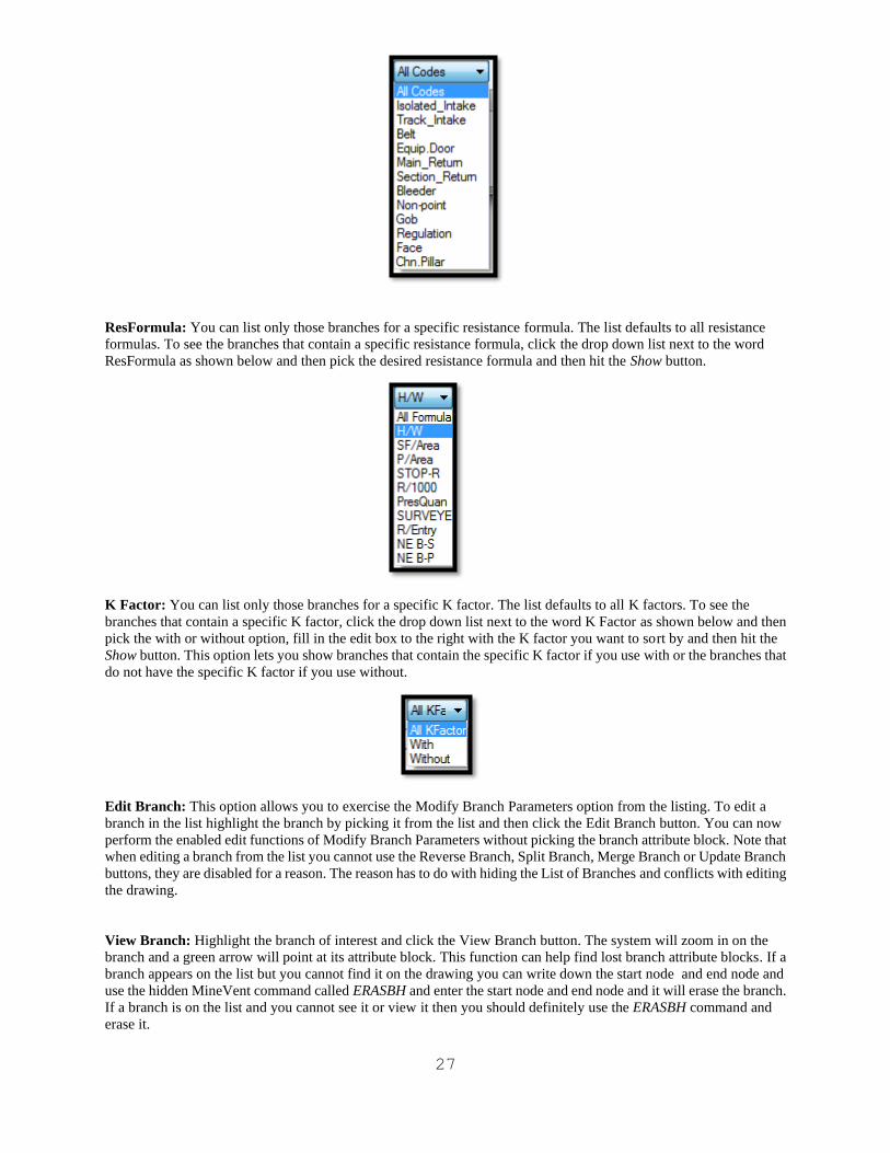
K Factor: You can list only those branches for a specific K factor. The list defaults to all K factors. To see the
branches that contain a specific K factor, click the drop down list next to the word K Factor as shown below and then
pick the with or without option, fill in the edit box to the right with the K factor you want to sort by and then hit the
Show button. This option lets you show branches that contain the specific K factor if you use with or the branches that
do not have the specific K factor if you use without.
Edit Branch: This option allows you to exercise the Modify Branch Parameters option from the listing. To edit a
branch in the list highlight the branch by picking it from the list and then click the Edit Branch button. You can now
perform the enabled edit functions of Modify Branch Parameters without picking the branch attribute block. Note that
when editing a branch from the list you cannot use the Reverse Branch, Split Branch, Merge Branch or Update Branch
buttons, they are disabled for a reason. The reason has to do with hiding the List of Branches and conflicts with editing
the drawing.
View Branch: Highlight the branch of interest and click the View Branch button. The system will zoom in on the
branch and a green arrow will point at its attribute block. This function can help find lost branch attribute blocks. If a
branch appears on the list but you cannot find it on the drawing you can write down the start node and end node and
use the hidden MineVent command called ERASBH and enter the start node and end node and it will erase the branch.
If a branch is on the list and you cannot see it or view it then you should definitely use the ERASBH command and
erase it.
28
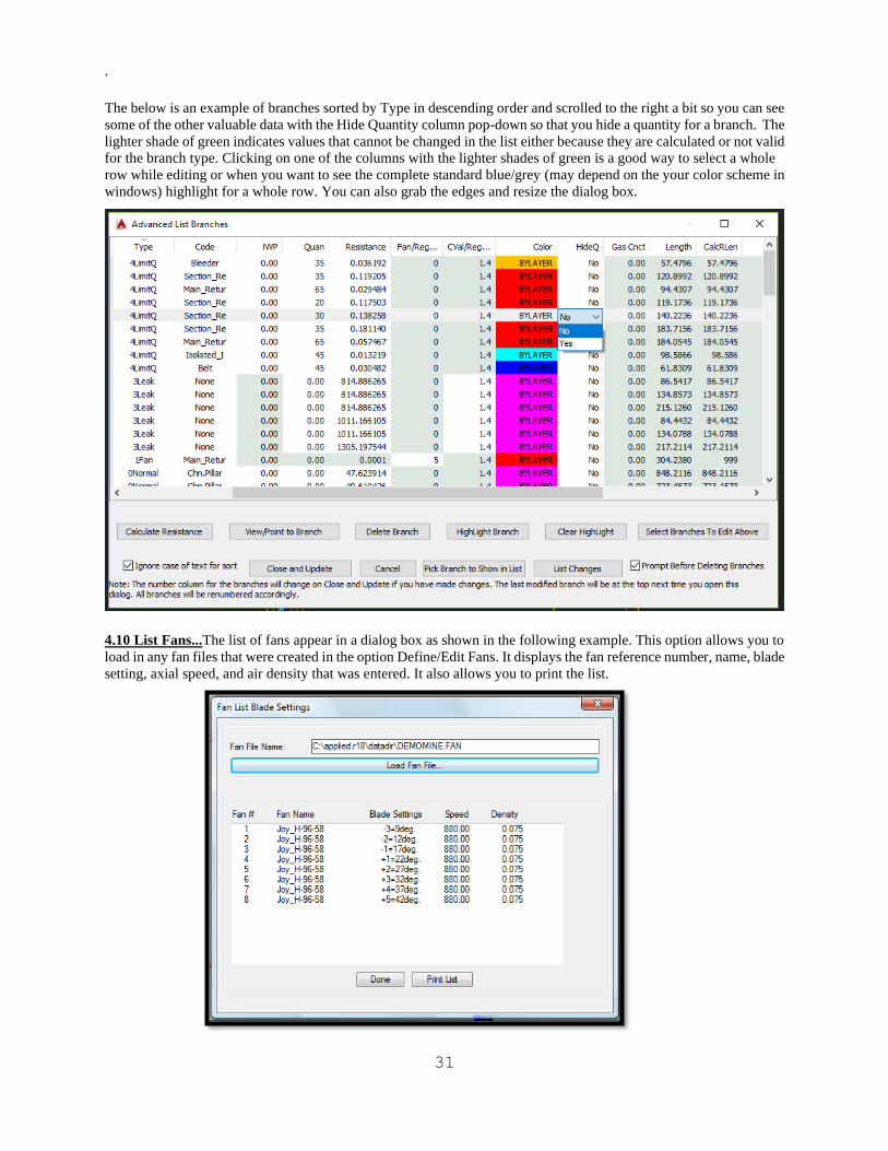
Print List: This option allows you to print a list of all the branches in the list box. When you click this option, the
following dialog box of printing options appears.
You can attach an identifying header to print; up to four lines and 80 characters per line are allowed. You must also
select the print mode. By default the output goes to the LPT1 printer port. Since most printers are USB the best option
is to use a network printer and re-direct LPT1 to the network printer.
One way to do this is:
1. Go to Windows Accessories and select Command Prompt.
2. At the command prompt type in: net use lpt1 \\server\printername
3. Ask your Network Administrator for the server and printer name.
CAUTION: If you try to print to LPT1 and there is no printer attached to the port or LPT1 is not re-directed to a valid
network printer then the computer may freeze. In this case it is best to print to a file and open it in Notepad, Microsoft
Word or any other word processor or text editor to print it from there. This also has the advantage of letting you
change the fonts and other text formatting.
The Set-up button brings up another dialog box, as shown below, for selecting the printer type and port. Since most
printers are Hp Compatibles this is the only option right now. We may print directly to all Windows printers in the
future but at this point it is about the same as printing to a file and opening it in Notepad or any other word processor.
You should normally hit Set as default and quit to exit out of this dialog box.
29
4.9 Advanced List Branches...
This option list the branches and ALL associated data (except some of the number details in Calculate Resistance) in a
sort of a form view. Even the data in Calculate Resistance can be seen if you select a branch in the list and click the
Calculate Resistance button. When you select this option the following dialog box appears:
(Sorted by Num Ascending)
Note: Use the Horizontal scroll bar at the bottom to see all the data to the right or resize the dialog at the edges.
→Sorts any column/parameter ascending on first click and descending on second click.
→Shows the arrow at the top indicating sort direction.
→You can sort by several parameters by doing the third most important first , then the second, then the Primary
parameter last.

30
→The light green columns are the disabled data not appropriate for the branch type as well as any data that is not
modifiable. So if, for example, you cannot edit or enter something such as a quantity then the branch type is not one
that accepts a quantity. The best example is the Fan/RegulatorWidthMax column as it is only available for fan
branches or regulator branches. The Cvalue/RegulatorHeight column is only available for Leak branches and regulator
branches.
→Other than Branch Name the edit boxes will only accept valid numbers.
→Pressing Enter during an edit of a edit box or dropdown does not close the dialog. Pressing Enter again will and ask
you if you want to save if changes have been made.
→On really large drawings clicking the header to sort may take 2 seconds or so.
→There is some Error checking on Regulator branches for calculate resistance.
Note: any branch that uses data in the list to Calculate Resistance should be entered before pressing the Calculate
Resistance button. The main ones for Regulator Branch are: Quan, HeightMax and WidthMAX. For the leakage
branches the Cvalue if using the STOP-R formula.
→Unlimited Branches in the List. However, the HC method currently at 4000 can be increased. The Gradient should
only be limited by the memory on the computer.
→Shows the branch color text correct for White/Black AutoCAD background. If you use some shade of grey there
could still be a problem but it should not be a big issue.
→Now has all the branch data in the List including the branch, polyline and arrow handles. You can sort by anything.
→Delete button should also never fail to delete any hidden or duplicate branch or any branch you do not like in the
list/drawing. Important Note: If you delete a branch from the list it is gone for good even if you click Cancel. For
this reason it pops up a warning to confirm the delete. If you want to Delete several branches and you don’t want to
be warned for each one then you can uncheck the checkbox which says Prompt Before Deleting Branches.
→Calculate Resistance button brings up the standard calculate resistance dialog for the currently highlighted
branch. Remember the above note and fill in any data needed before you click this button.
→View/Point to Branch Button simply points to the branch selected and ask to erase the arrow then if you want to
zoom previous.
→Highlight Branch Button highlights the selected branch in Magenta with a thick polyline width. Although it does
not currently Zoom to the area where the branch exist in the drawing.
→Clear Highlight Button Clears any and all branches that have been highlighted using the Highlight Branch button.
→Select Branches to Edit Above Button Allows you to draw a closed polygon around just a group of branches in the
drawing you want to edit in the list.
→Ignore case of text for sort checkbox does not consider the capital letters as such lower case should come first
such that zzz is better than AAA even in descending.
→Close and Update Button Closes the dialog and updates the changes in the drawing.
→Cancel Button Closes the dialog without saving changes but prompts you if changes have been made to be sure you
want to cancel and lose the changes.
→Pick Branch to Show in List Button allows you to pick a branch on the drawing and will highlight it in the list.
→List Changes Button List all the changes you have made in the current editing session.
31
.
The below is an example of branches sorted by Type in descending order and scrolled to the right a bit so you can see
some of the other valuable data with the Hide Quantity column pop-down so that you hide a quantity for a branch. The
lighter shade of green indicates values that cannot be changed in the list either because they are calculated or not valid
for the branch type. Clicking on one of the columns with the lighter shades of green is a good way to select a whole
row while editing or when you want to see the complete standard blue/grey (may depend on the your color scheme in
windows) highlight for a whole row. You can also grab the edges and resize the dialog box.
4.10 List Fans...The list of fans appear in a dialog box as shown in the following example. This option allows you to
load in any fan files that were created in the option Define/Edit Fans. It displays the fan reference number, name, blade
setting, axial speed, and air density that was entered. It also allows you to print the list.

32
4.11 Configure Branches
The branch configuration file contains the color, line type and default parameter values for calculating the resistance
for each branch code. The parameter values you specify will appear as the code defaults in the resistance calculation
edit box when you are creating a new branch or modifying an existing branch. When you select this option, the
following dialog box appears.
Each ventilation drawing can have a unique branch configuration file. A default configuration file called
VENTCODE.CFG is provided with the software and is automatically loaded into the configuration file (drawing
name).cfg. You can edit the file as required. Some parameters are not relevant to all branch codes and can be ignored,
for example, a leakage branch will have stoppings but not a normal branch.
Branch Code-Description: Branch codes are used to specify a group of branches that will have the same appearance
on the drawing, i.e., the color, line type and branches for which a common set of parameters will be used to compute
the branch resistance. The list of codes and their default names are given in the code list, but you can customize the
names by adding a Description which will appear in all references to the branch code in other options. The Description
display will accommodate a maximum of 15 lower case or 12 upper case characters.
Tabulate Branch Quantities for this Code: This checkbox tells the MineVent program to sum up the quantities for
branches that use this code. The "tabulated" or summed-up quantities will be listed in the Review Network Messages
after the MineVent program has run.
Branch Code Cosmetics: You can specify a default Color and Line Type: for each code.
Color: You can select the color by scrolling through the drop down list or type in the color. Except for the
standard AutoCAD colors, the color are designated by a number. When you select or type in a color number,
the actual color shows in the dialog box, so you will know how the branch will appear in the drawing. To
assign a color by typing, key in the number and press the Enter key. Adjacent color numbers tend to be
similar in appearance. This feature makes it easy to assign different shades of one standard color to a common
group of branches, such as all intakes.
Line Type: You must select the line type from the drop down list of standard AutoCAD line types. If you
really need a line type that is not in the drop down list you can edit the cfg file manually in Notepad.
Numerical Branch Code Data:: You can assign default dimensions to the various parameters which are used to
compute the branch resistance. All parameters are given a default value, but not all apply to a specific branch code. For
example, the formula for calculating resistance for an intake does not use information about stoppings which are
applicable only to leakage branches. In addition, you may want to compute the resistance for rectangular intakes using

33
the height-width formula and other shaped intakes with the perimeter, area and shape factor information. Therefore the
area default does not need to equal the product of the airway height multiplied by airway width.
4.12 Global Resistance Change: Use this option to change the resistance of multiple branches. The resistance can
be changed for all branches with a specified name, code, type, formula and/or selection. It can also change branches
regardless of name, code, type, formula or selection set by choosing ALL in the edit box or pop down lists.
When you select this option, the following dialog box appears.
Most of the information here is also in the help file if you click the help button on the dialog. However,
the below is easier to read and has important information.
The program has the ability to change branches based on surveyed data from a file using the SURVEYED: Formula
Pressure and Quantity From File. But you must have the dwgname.P and dwgname.Q files for this to work. If either of
those files do not exist it terminates. If there is a missing branch/node in one of those files or bad data then you can
either Ignore, Edit for that branch or Abort. If you choose to Abort it will stop the program but the previous branches
before you hit abort will still be updated with the new resistance data.
Enhancements:
→Uses Length from Calculate R when possible. Usually the same as the polyline length but could differ
→More flexibility and ease for branches that use or do not use Equal Branches in Parallel (EQ-BP)
Resistance Formula to Use At Top Left Main Resistance Formula:
Use this list box to select the formula that will replace the existing formulas in the desired branches. This is the formula
that will be used to calculate (and replace) all the branch resistances to be changed based on the Filters for Global
Change.
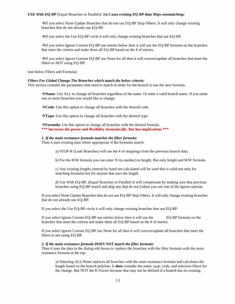
34
USE With EQ-BP (Equal Branches in Parallel): 1st 2 uses existing EQ-BP data Skips nonmatching:
→If you select None Update Branches that do not use EQ-BP Skip Others. It will only change existing
branches that do not already use EQ-BP.
→If you select the Use EQ-BP circle it will only change existing branches that use EQ-BP.
→If you select Ignore Current EQ-BP use entries below then it will use the EQ-BP formula on the branches
that meet the criteria and make them all EQ-BP based on the # of entries.
→If you select Ignore Current EQ-BP use None for all then it will convert/update all branches that meet the
filters to NOT using EQ-BP.
(see below Filters and Formula)
Filters For Global Change The Branches which match the below criteria:
This section contains the parameters that need to match in order for the branch to use the new formula.
→Name: Use ALL to change all branches regardless of the name. Or enter a valid branch name. If you name
one or more branches you would like to change.
→Code: Use this option to change all branches with the desired code.
→Type: Use this option to change all branches with the desired type.
→Formula: Use this option to change all branches with the desired formula.
*** Increases the power and flexibility dramatically. But has implications ***
1. If the main resistance formula matches the filter formula:
Then it uses existing data where appropriate if the formulas match:
a) STOP-R (Leak Branches) will use the # of stoppings from the previous branch data.
b) For the H/W formula you can enter X+(a number) to height. But only height and H/W formula.
c) Any existing lengths entered by hand not calculated will be used this is valid not only for
matching formulas but for anyone that uses the length.
d) Use With EQ-BP. (Equal Branches in Parallel) It will compensate by making sure that previous
branches using EQ-BP match and skip any that do not.Unless you use one of the Ignore options.
If you select None Update Branches that do not use EQ-BP Skip Others. It will only change existing branches
that do not already use EQ-BP.
If you select the Use EQ-BP circle it will only change existing branches that use EQ-BP.
If you select Ignore Current EQ-BP use entries below then it will use the EQ-BP formula on the
branches that meet the criteria and make them all EQ-BP based on the # of entries.
If you select Ignore Current EQ-BP use None for all then it will convert/update all branches that meet the
filters to not using EQ-BP.
2. If the main resistance formula DOES NOT match the filter formula:
Then it uses the data in the dialog edit boxes to replace the branches with the filter formula with the main
resistance formula at the top:
a) Selecting ALL/None replaces all branches with the main resistance formula and calculates the
length based on the branch polyline. It does consider the name, type, code, and selection filters for
the change. But NOT the K-Factor because that may not be defined if a branch has no existing
35
resistance data. THIS OPTION COULD BE POWERFUL FOR CHANGING ALL OR A GROUP
OF Branches TO A DESIRED RESISTANCE ALL AT ONCE. SUCH AS THE SURVERYED
FORMULA: Pressure and Quantity from file. Or any formula for that matter. Surveyed likely would
make the most sense.
b) If the filter formula is Not ALL then it will use existing branch resistance data for the length when
applicable. Note: For formulas that use the length Calculate Resistance allows the user to enter a
length that is NOT the actual polyline length which it initially calculates.
c) USE EQ-BP: If filter formula is ALL it replaces all branches matching the other criteria to EQ-BP
or None regardless of what their state was before. The ignore options are available. For branches
that have a resistance formula based on the number of entries. Basically everything except the last
one R/Entry. If the Filter Formula is not the main it will still convert based on the number of entries
in the “other/old” formula.
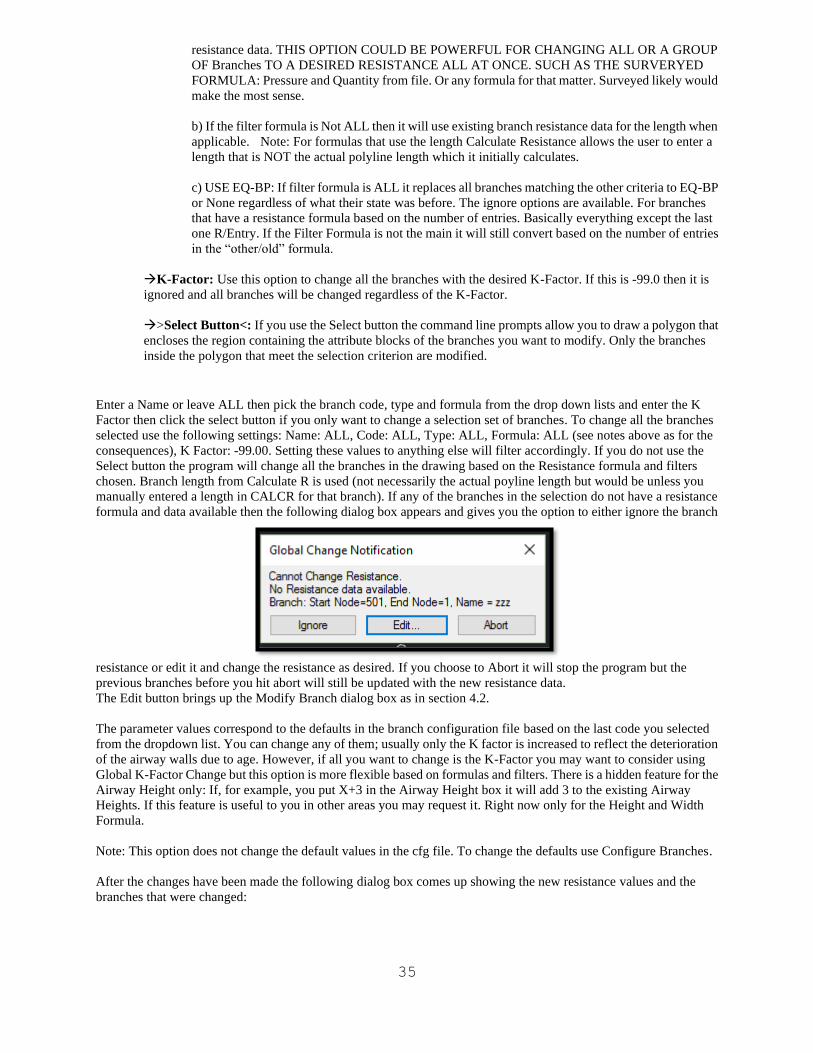
→K-Factor: Use this option to change all the branches with the desired K-Factor. If this is -99.0 then it is
ignored and all branches will be changed regardless of the K-Factor.
→>Select Button<: If you use the Select button the command line prompts allow you to draw a polygon that
encloses the region containing the attribute blocks of the branches you want to modify. Only the branches
inside the polygon that meet the selection criterion are modified.
Enter a Name or leave ALL then pick the branch code, type and formula from the drop down lists and enter the K
Factor then click the select button if you only want to change a selection set of branches. To change all the branches
selected use the following settings: Name: ALL, Code: ALL, Type: ALL, Formula: ALL (see notes above as for the
consequences), K Factor: -99.00. Setting these values to anything else will filter accordingly. If you do not use the
Select button the program will change all the branches in the drawing based on the Resistance formula and filters
chosen. Branch length from Calculate R is used (not necessarily the actual poyline length but would be unless you
manually entered a length in CALCR for that branch). If any of the branches in the selection do not have a resistance
formula and data available then the following dialog box appears and gives you the option to either ignore the branch
resistance or edit it and change the resistance as desired. If you choose to Abort it will stop the program but the
previous branches before you hit abort will still be updated with the new resistance data.
The Edit button brings up the Modify Branch dialog box as in section 4.2.
The parameter values correspond to the defaults in the branch configuration file based on the last code you selected
from the dropdown list. You can change any of them; usually only the K factor is increased to reflect the deterioration
of the airway walls due to age. However, if all you want to change is the K-Factor you may want to consider using
Global K-Factor Change but this option is more flexible based on formulas and filters. There is a hidden feature for the
Airway Height only: If, for example, you put X+3 in the Airway Height box it will add 3 to the existing Airway
Heights. If this feature is useful to you in other areas you may request it. Right now only for the Height and Width
Formula.
Note: This option does not change the default values in the cfg file. To change the defaults use Configure Branches.
After the changes have been made the following dialog box comes up showing the new resistance values and the
branches that were changed:
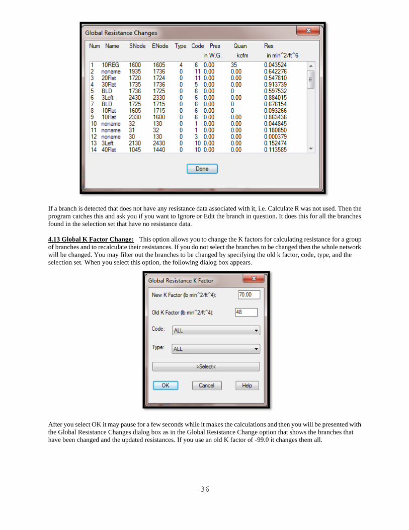
36
If a branch is detected that does not have any resistance data associated with it, i.e. Calculate R was not used. Then the
program catches this and ask you if you want to Ignore or Edit the branch in question. It does this for all the branches
found in the selection set that have no resistance data.
4.13 Global K Factor Change: This option allows you to change the K factors for calculating resistance for a group
of branches and to recalculate their resistances. If you do not select the branches to be changed then the whole network
will be changed. You may filter out the branches to be changed by specifying the old k factor, code, type, and the
selection set. When you select this option, the following dialog box appears.
After you select OK it may pause for a few seconds while it makes the calculations and then you will be presented with
the Global Resistance Changes dialog box as in the Global Resistance Change option that shows the branches that
have been changed and the updated resistances. If you use an old K factor of -99.0 it changes them all.
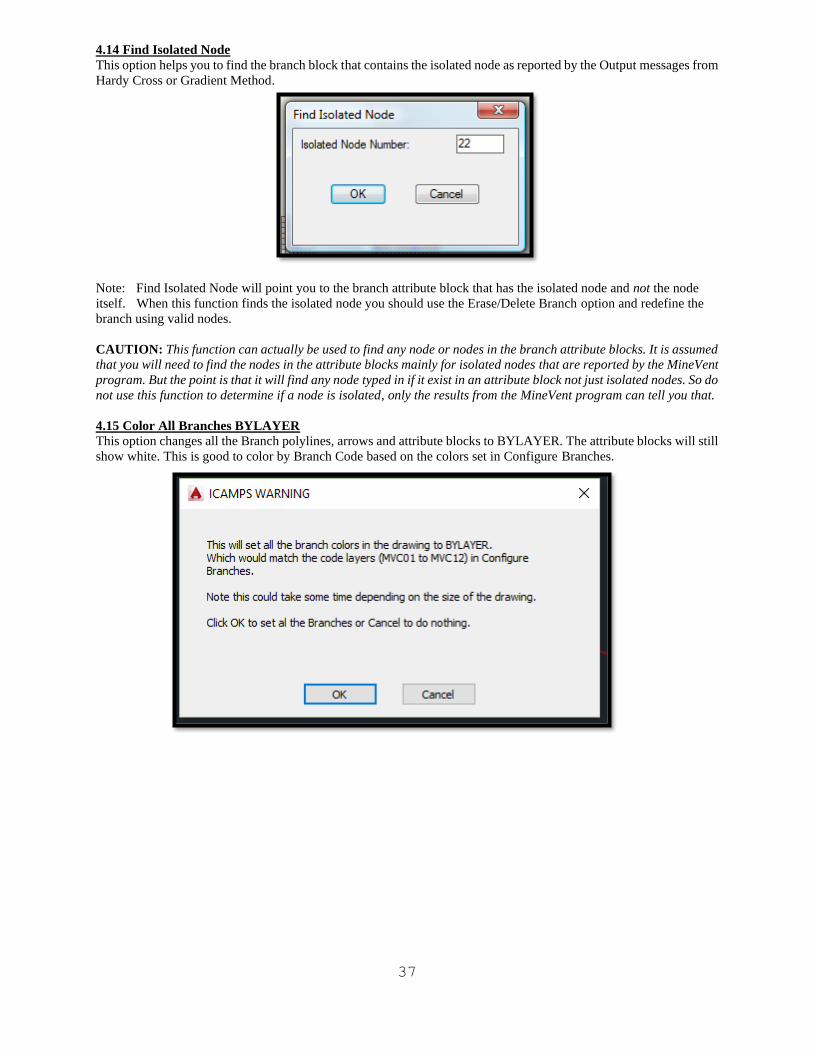
37
4.14 Find Isolated Node
This option helps you to find the branch block that contains the isolated node as reported by the Output messages from
Hardy Cross or Gradient Method.
Note: Find Isolated Node will point you to the branch attribute block that has the isolated node and not the node
itself. When this function finds the isolated node you should use the Erase/Delete Branch option and redefine the
branch using valid nodes.
CAUTION: This function can actually be used to find any node or nodes in the branch attribute blocks. It is assumed
that you will need to find the nodes in the attribute blocks mainly for isolated nodes that are reported by the MineVent
program. But the point is that it will find any node typed in if it exist in an attribute block not just isolated nodes. So do
not use this function to determine if a node is isolated, only the results from the MineVent program can tell you that.
4.15 Color All Branches BYLAYER
This option changes all the Branch polylines, arrows and attribute blocks to BYLAYER. The attribute blocks will still
show white. This is good to color by Branch Code based on the colors set in Configure Branches.
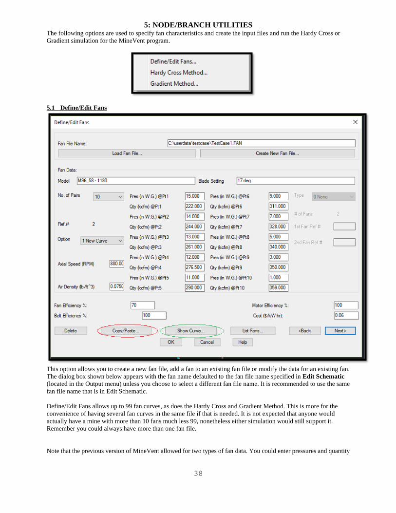
38
5: NODE/BRANCH UTILITIES The following options are used to specify fan characteristics and create the input files and run the Hardy Cross or
Gradient simulation for the MineVent program.
5.1 Define/Edit Fans
This option allows you to create a new fan file, add a fan to an existing fan file or modify the data for an existing fan.
The dialog box shown below appears with the fan name defaulted to the fan file name specified in Edit Schematic
(located in the Output menu) unless you choose to select a different fan file name. It is recommended to use the same
fan file name that is in Edit Schematic.
Define/Edit Fans allows up to 99 fan curves, as does the Hardy Cross and Gradient Method. This is more for the
convenience of having several fan curves in the same file if that is needed. It is not expected that anyone would
actually have a mine with more than 10 fans much less 99, nonetheless either simulation would still support it.
Remember you could always have more than one fan file.
Note that the previous version of MineVent allowed for two types of fan data. You could enter pressures and quantity

39
data from a fan curve, or provide the coefficients from a theoretical quadratic fan curve. The new version does not
allow you to enter coefficients for a theoretical curve.
CAUTION: Enter pressure and quantity data accurately e.g. if the quantity at a point is 232, enter 232 not 230. Put
as many points on the fan curve as you can to help convergence.
Load Fan File: Click this button to edit an existing fan file. A standard AutoCAD file open dialog box will appear
with the pattern extension .FAN. Browse your existing files for the fan file to edit.
Create New Fan File: Click this button to create a new fan file. A standard AutoCAD file creation dialog box will
appear with the pattern extension .FAN. Note: Each fan file can contain up to 99 fan curves.
Fan Data: The options for creating and editing a fan follow: If you are creating a new fan file a blank screen will
appear with the number of pairs defaulted to three. If you are editing an existing file, data for the first curve fan in the
file will appear. Use the <Back and Next> options below to display the desired set of fan data.
.
Model: Enter a descriptor for the fan; up to 35 characters are allowed. The default name is Noname
Blade Setting: Enter the blade setting number, 35 characters max. Blade setting corresponds to one of the 50 fans.
No. Of Pairs: You must specify the number of pressure/quantity pairs you want to enter from the fan curve
anywhere from 3 to10. After you enter the number of pairs, edit boxes for the unused pairs will be grayed out.
Ref. #: This number is automatically assigned. Normally, it starts at 1 and increments from there each time you define
a new fan . If you delete a fan it does not change the fan numbers of the rest of the fans but the next new fan you define
will pick up at any missing numbers or just increment by 1. When you defined a fan branch, the fan reference number
you assign to that branch must corresponds to one of the fan curve reference numbers. Each fan file can contain up to
fifty fan curves.
Option: This pull down provides two sub-options: New Curve and Modify Curve. New Curve allows you to enter
pressure and quantity data and Modify Curve allows you to enter Type data for existing fan curves.
New Curve: This option allows you to enter pressure and quantity data from a new fan curve. The edit boxes for
Types and related data will be grayed out. You specify the No. Of Pairs of pressures and quantities from the fan curve,
note the fan Ref. #, enter the corresponding pressure and quantity values from the fan curve, the Axial Speed of the fan
and the Air Density.
Modify Curve: This option lets you change the Axial Speed and Air Density for an existing fans or combine two or
more existing fans in series or parallel to form an equivalent fan with its own fan reference number.
Pres @ Px: Enter the pressure for point x. Enter the pressures sequential, beginning with the first or left most point of
the fan curve. In imperial units the pressure is given in inches of water gauge.
Qty @ Px: Enter the pressure for point x. Enter the quantities sequentially, beginning with the first or left most point
of the fan curve. In imperial units the quantity is given in ten thousand cubic feet per minute.
Axial Speed: Enter the axial speed.
Air Density: Enter the air density.
Type: If you selected Modify Curve then the Types will be enabled (not grayed out). When you select the Type pull
down, the following pull down list of modification options appears. None means none selected.
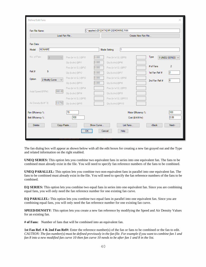
40
The fan dialog box will appear as shown below with all the edit boxes for creating a new fan grayed out and the Type
and related information on the right enabled.
UNEQ SERIES: This option lets you combine two equivalent fans in series into one equivalent fan. The fans to be
combined must already exist in the file. You will need to specify fan reference numbers of the fans to be combined.
UNEQ PARALLEL: This option lets you combine two non-equivalent fans in parallel into one equivalent fan. The
fans to be combined must already exist in the file. You will need to specify the fan reference numbers of the fans to be
combined.
EQ SERIES: This option lets you combine two equal fans in series into one equivalent fan. Since you are combining
equal fans, you will only need the fan reference number for one existing fan curve.
EQ PARALLEL: This option lets you combine two equal fans in parallel into one equivalent fan. Since you are
combining equal fans, you will only need the fan reference number for one existing fan curve.
SPEED/DENSITY: This option lets you create a new fan reference by modifying the Speed and Air Density Values
for an existing fan.
# of Fans: Number of fans that will be combined into an equivalent fan.
1st Fan Ref. # & 2nd Fan Ref#: Enter the reference number(s) of the fan or fans to be combined or the fan to edit.
CAUTION: The fan number(s) must be defined previously in the fan file. For example if you want to combine fan 1 and
fan 8 into a new modified fan curve 10 then fan curve 10 needs to be after fan 1 and 8 in the list.
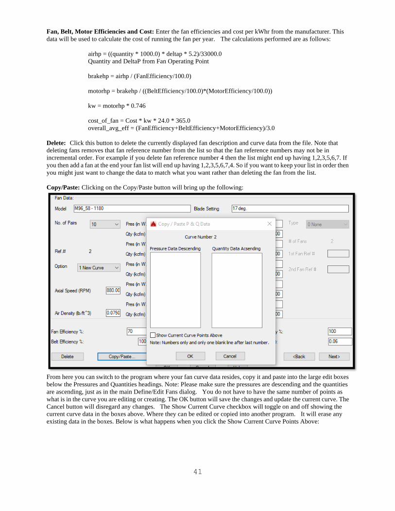
41
Fan, Belt, Motor Efficiencies and Cost: Enter the fan efficiencies and cost per kWhr from the manufacturer. This
data will be used to calculate the cost of running the fan per year. The calculations performed are as follows:
airhp = ((quantity * 1000.0) * deltap * 5.2)/33000.0
Quantity and DeltaP from Fan Operating Point
brakehp = airhp / (FanEfficiency/100.0)
motorhp = brakehp / ((BeltEfficiency/100.0)*(MotorEfficiency/100.0))
kw = motorhp * 0.746
cost_of_fan = Cost * kw * 24.0 * 365.0
overall_avg_eff = (FanEfficiency+BeltEfficiency+MotorEfficiency)/3.0
Delete: Click this button to delete the currently displayed fan description and curve data from the file. Note that
deleting fans removes that fan reference number from the list so that the fan reference numbers may not be in
incremental order. For example if you delete fan reference number 4 then the list might end up having 1,2,3,5,6,7. If
you then add a fan at the end your fan list will end up having 1,2,3,5,6,7,4. So if you want to keep your list in order then
you might just want to change the data to match what you want rather than deleting the fan from the list.
Copy/Paste: Clicking on the Copy/Paste button will bring up the following:
From here you can switch to the program where your fan curve data resides, copy it and paste into the large edit boxes
below the Pressures and Quantities headings. Note: Please make sure the pressures are descending and the quantities
are ascending, just as in the main Define/Edit Fans dialog. You do not have to have the same number of points as
what is in the curve you are editing or creating. The OK button will save the changes and update the current curve. The
Cancel button will disregard any changes. The Show Current Curve checkbox will toggle on and off showing the
current curve data in the boxes above. Where they can be edited or copied into another program. It will erase any
existing data in the boxes. Below is what happens when you click the Show Current Curve Points Above:
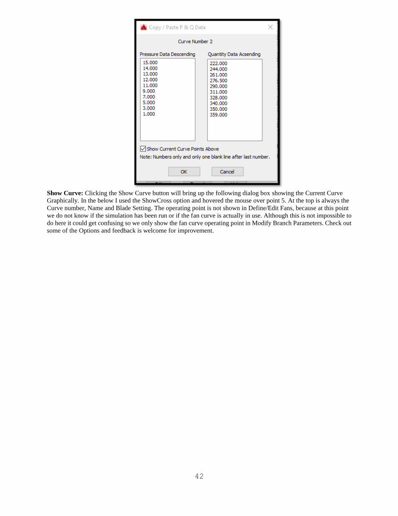
42
Show Curve: Clicking the Show Curve button will bring up the following dialog box showing the Current Curve
Graphically. In the below I used the ShowCross option and hovered the mouse over point 5. At the top is always the
Curve number, Name and Blade Setting. The operating point is not shown in Define/Edit Fans, because at this point
we do not know if the simulation has been run or if the fan curve is actually in use. Although this is not impossible to
do here it could get confusing so we only show the fan curve operating point in Modify Branch Parameters. Check out
some of the Options and feedback is welcome for improvement.

43
List Fans: Click this option to display a list of the fans in this file. This option brings up the same dialog box as does
List Fans in the Branch menu.
<Back: Click this button to view or edit the information for the previous fan in the file.
Next>: Click this button to view or edit the information for the next fan in the file. If you reach the last fan in the file,
the following dialog box appears.
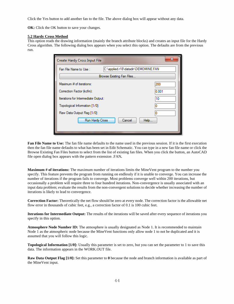
44
Click the Yes button to add another fan to the file. The above dialog box will appear without any data.
OK: Click the OK button to save your changes.
5.2 Hardy Cross Method
This option reads the drawing information (mainly the branch attribute blocks) and creates an input file for the Hardy
Cross algorithm. The following dialog box appears when you select this option. The defaults are from the previous
run.
Fan File Name to Use: The fan file name defaults to the name used in the previous session. If it is the first execution
then the fan file name defaults to what has been set in Edit Schematic. You can type in a new fan file name or click the
Browse Existing Fan Files button to select from the list of existing fan files. When you click the button, an AutoCAD
file open dialog box appears with the pattern extension .FAN.
Maximum # of iterations: The maximum number of iterations limits the MineVent program to the number you
specify. This feature prevents the program from running on endlessly if it is unable to converge. You can increase the
number of iterations if the program fails to converge. Most problems converge well within 200 iterations, but
occasionally a problem will require three to four hundred iterations. Non-convergence is usually associated with an
input data problem; evaluate the results from the non-convergent solutions to decide whether increasing the number of
iterations is likely to lead to convergence.
Correction Factor: Theoretically the net flow should be zero at every node. The correction factor is the allowable net
flow error in thousands of cubic feet, e.g., a correction factor of 0.1 is 100 cubic feet.
Iterations for Intermediate Output: The results of the iterations will be saved after every sequence of iterations you
specify in this option.
Atmosphere Node Number ID: The atmosphere is usually designated as Node 1. It is recommended to maintain
Node 1 as the atmospheric node because the MineVent functions only allow node 1 to not be duplicated and it is
assumed that you will follow this logic.
Topological Information [1/0]: Usually this parameter is set to zero, but you can set the parameter to 1 to save this
data. The information appears in the WORK.OUT file.
Raw Data Output Flag [1/0]: Set this parameter to 0 because the node and branch information is available as part of
the MineVent input.
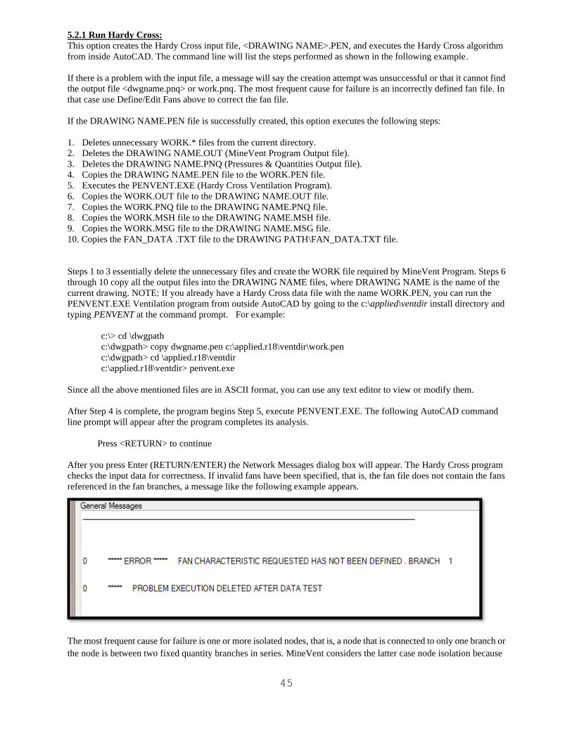
45
5.2.1 Run Hardy Cross:
This option creates the Hardy Cross input file, <DRAWING NAME>.PEN, and executes the Hardy Cross algorithm
from inside AutoCAD. The command line will list the steps performed as shown in the following example.
If there is a problem with the input file, a message will say the creation attempt was unsuccessful or that it cannot find
the output file <dwgname.pnq> or work.pnq. The most frequent cause for failure is an incorrectly defined fan file. In
that case use Define/Edit Fans above to correct the fan file.
If the DRAWING NAME.PEN file is successfully created, this option executes the following steps:
1. Deletes unnecessary WORK.* files from the current directory.
2. Deletes the DRAWING NAME.OUT (MineVent Program Output file).
3. Deletes the DRAWING NAME.PNQ (Pressures & Quantities Output file).
4. Copies the DRAWING NAME.PEN file to the WORK.PEN file.
5. Executes the PENVENT.EXE (Hardy Cross Ventilation Program).
6. Copies the WORK.OUT file to the DRAWING NAME.OUT file.
7. Copies the WORK.PNQ file to the DRAWING NAME.PNQ file.
8. Copies the WORK.MSH file to the DRAWING NAME.MSH file.
9. Copies the WORK.MSG file to the DRAWING NAME.MSG file.
10. Copies the FAN_DATA .TXT file to the DRAWING PATH\FAN_DATA.TXT file.
Steps 1 to 3 essentially delete the unnecessary files and create the WORK file required by MineVent Program. Steps 6
through 10 copy all the output files into the DRAWING NAME files, where DRAWING NAME is the name of the
current drawing. NOTE: If you already have a Hardy Cross data file with the name WORK.PEN, you can run the
PENVENT.EXE Ventilation program from outside AutoCAD by going to the c:\applied\ventdir install directory and
typing PENVENT at the command prompt. For example:
c:\> cd \dwgpath
c:\dwgpath> copy dwgname.pen c:\applied.r18\ventdir\work.pen
c:\dwgpath> cd \applied.r18\ventdir
c:\applied.r18\ventdir> penvent.exe
Since all the above mentioned files are in ASCII format, you can use any text editor to view or modify them.
After Step 4 is complete, the program begins Step 5, execute PENVENT.EXE. The following AutoCAD command
line prompt will appear after the program completes its analysis.
Press <RETURN> to continue
After you press Enter (RETURN/ENTER) the Network Messages dialog box will appear. The Hardy Cross program
checks the input data for correctness. If invalid fans have been specified, that is, the fan file does not contain the fans
referenced in the fan branches, a message like the following example appears.
The most frequent cause for failure is one or more isolated nodes, that is, a node that is connected to only one branch or
the node is between two fixed quantity branches in series. MineVent considers the latter case node isolation because
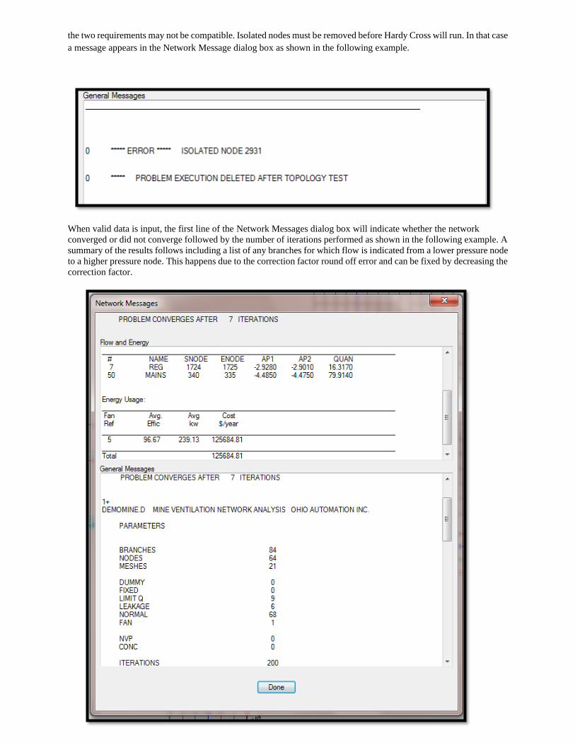
46
the two requirements may not be compatible. Isolated nodes must be removed before Hardy Cross will run. In that case
a message appears in the Network Message dialog box as shown in the following example.
When valid data is input, the first line of the Network Messages dialog box will indicate whether the network
converged or did not converge followed by the number of iterations performed as shown in the following example. A
summary of the results follows including a list of any branches for which flow is indicated from a lower pressure node
to a higher pressure node. This happens due to the correction factor round off error and can be fixed by decreasing the
correction factor.
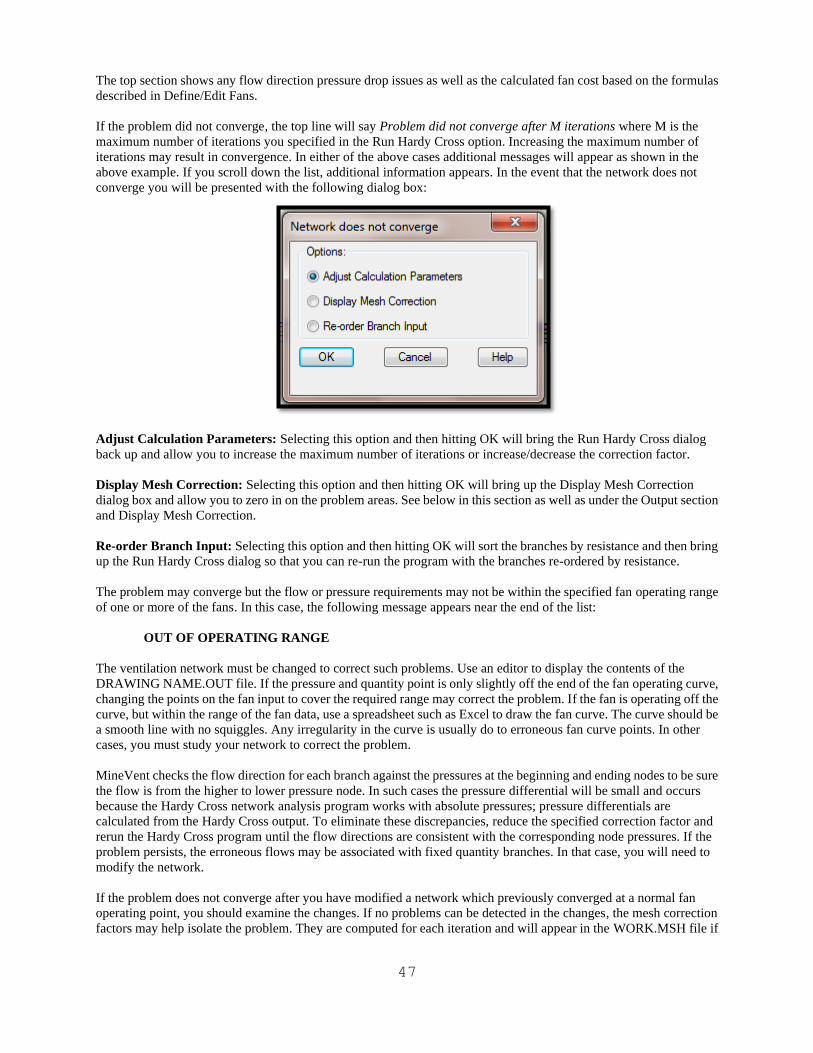
47
The top section shows any flow direction pressure drop issues as well as the calculated fan cost based on the formulas
described in Define/Edit Fans.
If the problem did not converge, the top line will say Problem did not converge after M iterations where M is the
maximum number of iterations you specified in the Run Hardy Cross option. Increasing the maximum number of
iterations may result in convergence. In either of the above cases additional messages will appear as shown in the
above example. If you scroll down the list, additional information appears. In the event that the network does not
converge you will be presented with the following dialog box:
Adjust Calculation Parameters: Selecting this option and then hitting OK will bring the Run Hardy Cross dialog
back up and allow you to increase the maximum number of iterations or increase/decrease the correction factor.
Display Mesh Correction: Selecting this option and then hitting OK will bring up the Display Mesh Correction
dialog box and allow you to zero in on the problem areas. See below in this section as well as under the Output section
and Display Mesh Correction.
Re-order Branch Input: Selecting this option and then hitting OK will sort the branches by resistance and then bring
up the Run Hardy Cross dialog so that you can re-run the program with the branches re-ordered by resistance.
The problem may converge but the flow or pressure requirements may not be within the specified fan operating range
of one or more of the fans. In this case, the following message appears near the end of the list:
OUT OF OPERATING RANGE
The ventilation network must be changed to correct such problems. Use an editor to display the contents of the
DRAWING NAME.OUT file. If the pressure and quantity point is only slightly off the end of the fan operating curve,
changing the points on the fan input to cover the required range may correct the problem. If the fan is operating off the
curve, but within the range of the fan data, use a spreadsheet such as Excel to draw the fan curve. The curve should be
a smooth line with no squiggles. Any irregularity in the curve is usually do to erroneous fan curve points. In other
cases, you must study your network to correct the problem.
MineVent checks the flow direction for each branch against the pressures at the beginning and ending nodes to be sure
the flow is from the higher to lower pressure node. In such cases the pressure differential will be small and occurs
because the Hardy Cross network analysis program works with absolute pressures; pressure differentials are
calculated from the Hardy Cross output. To eliminate these discrepancies, reduce the specified correction factor and
rerun the Hardy Cross program until the flow directions are consistent with the corresponding node pressures. If the
problem persists, the erroneous flows may be associated with fixed quantity branches. In that case, you will need to
modify the network.
If the problem does not converge after you have modified a network which previously converged at a normal fan
operating point, you should examine the changes. If no problems can be detected in the changes, the mesh correction
factors may help isolate the problem. They are computed for each iteration and will appear in the WORK.MSH file if
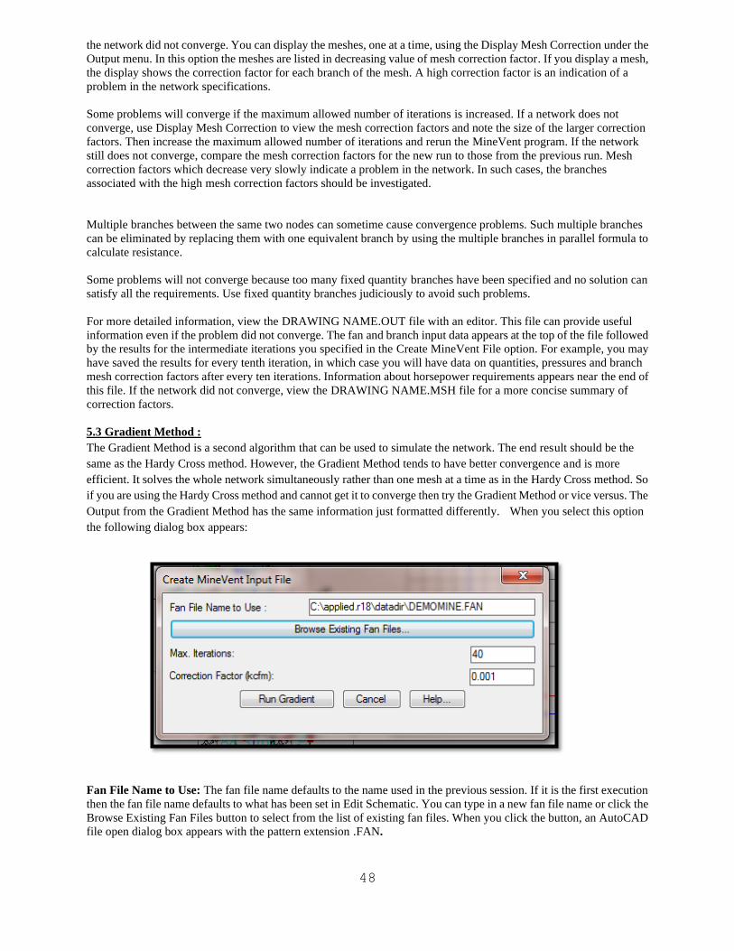
48
the network did not converge. You can display the meshes, one at a time, using the Display Mesh Correction under the
Output menu. In this option the meshes are listed in decreasing value of mesh correction factor. If you display a mesh,
the display shows the correction factor for each branch of the mesh. A high correction factor is an indication of a
problem in the network specifications.
Some problems will converge if the maximum allowed number of iterations is increased. If a network does not
converge, use Display Mesh Correction to view the mesh correction factors and note the size of the larger correction
factors. Then increase the maximum allowed number of iterations and rerun the MineVent program. If the network
still does not converge, compare the mesh correction factors for the new run to those from the previous run. Mesh
correction factors which decrease very slowly indicate a problem in the network. In such cases, the branches
associated with the high mesh correction factors should be investigated.
Multiple branches between the same two nodes can sometime cause convergence problems. Such multiple branches
can be eliminated by replacing them with one equivalent branch by using the multiple branches in parallel formula to
calculate resistance.
Some problems will not converge because too many fixed quantity branches have been specified and no solution can
satisfy all the requirements. Use fixed quantity branches judiciously to avoid such problems.
For more detailed information, view the DRAWING NAME.OUT file with an editor. This file can provide useful
information even if the problem did not converge. The fan and branch input data appears at the top of the file followed
by the results for the intermediate iterations you specified in the Create MineVent File option. For example, you may
have saved the results for every tenth iteration, in which case you will have data on quantities, pressures and branch
mesh correction factors after every ten iterations. Information about horsepower requirements appears near the end of
this file. If the network did not converge, view the DRAWING NAME.MSH file for a more concise summary of
correction factors.
5.3 Gradient Method :
The Gradient Method is a second algorithm that can be used to simulate the network. The end result should be the
same as the Hardy Cross method. However, the Gradient Method tends to have better convergence and is more
efficient. It solves the whole network simultaneously rather than one mesh at a time as in the Hardy Cross method. So
if you are using the Hardy Cross method and cannot get it to converge then try the Gradient Method or vice versus. The
Output from the Gradient Method has the same information just formatted differently. When you select this option
the following dialog box appears:
Fan File Name to Use: The fan file name defaults to the name used in the previous session. If it is the first execution
then the fan file name defaults to what has been set in Edit Schematic. You can type in a new fan file name or click the
Browse Existing Fan Files button to select from the list of existing fan files. When you click the button, an AutoCAD
file open dialog box appears with the pattern extension .FAN.
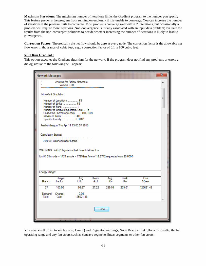
49
Maximum Iterations: The maximum number of iterations limits the Gradient program to the number you specify.
This feature prevents the program from running on endlessly if it is unable to converge. You can increase the number
of iterations if the program fails to converge. Most problems converge well within 20 iterations, but occasionally a
problem will require more iterations. Non-convergence is usually associated with an input data problem; evaluate the
results from the non-convergent solutions to decide whether increasing the number of iterations is likely to lead to
convergence.
Correction Factor: Theoretically the net flow should be zero at every node. The correction factor is the allowable net
flow error in thousands of cubic feet, e.g., a correction factor of 0.1 is 100 cubic feet.
5.3.1 Run Gradient :
This option executes the Gradient algorithm for the network. If the program does not find any problems or errors a
dialog similar to the following will appear:
You may scroll down to see fan cost, LimitQ and Regulator warnings, Node Results, Link (Branch) Results, the fan
operating range and any fan errors such as concave segments linear segments or other fan errors.
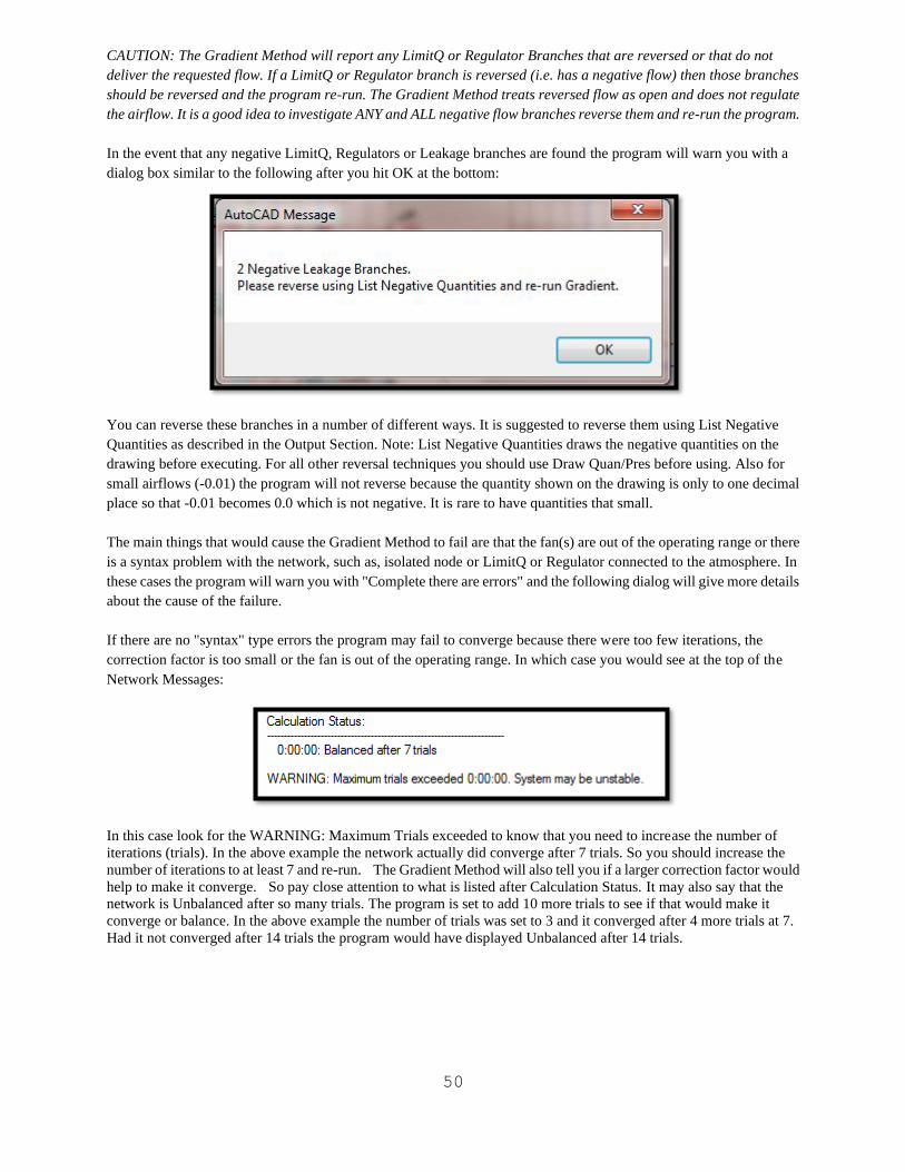
50
CAUTION: The Gradient Method will report any LimitQ or Regulator Branches that are reversed or that do not
deliver the requested flow. If a LimitQ or Regulator branch is reversed (i.e. has a negative flow) then those branches
should be reversed and the program re-run. The Gradient Method treats reversed flow as open and does not regulate
the airflow. It is a good idea to investigate ANY and ALL negative flow branches reverse them and re-run the program.
In the event that any negative LimitQ, Regulators or Leakage branches are found the program will warn you with a
dialog box similar to the following after you hit OK at the bottom:
You can reverse these branches in a number of different ways. It is suggested to reverse them using List Negative
Quantities as described in the Output Section. Note: List Negative Quantities draws the negative quantities on the
drawing before executing. For all other reversal techniques you should use Draw Quan/Pres before using. Also for
small airflows (-0.01) the program will not reverse because the quantity shown on the drawing is only to one decimal
place so that -0.01 becomes 0.0 which is not negative. It is rare to have quantities that small.
The main things that would cause the Gradient Method to fail are that the fan(s) are out of the operating range or there
is a syntax problem with the network, such as, isolated node or LimitQ or Regulator connected to the atmosphere. In
these cases the program will warn you with "Complete there are errors" and the following dialog will give more details
about the cause of the failure.
If there are no "syntax" type errors the program may fail to converge because there were too few iterations, the
correction factor is too small or the fan is out of the operating range. In which case you would see at the top of the
Network Messages:
In this case look for the WARNING: Maximum Trials exceeded to know that you need to increase the number of
iterations (trials). In the above example the network actually did converge after 7 trials. So you should increase the
number of iterations to at least 7 and re-run. The Gradient Method will also tell you if a larger correction factor would
help to make it converge. So pay close attention to what is listed after Calculation Status. It may also say that the
network is Unbalanced after so many trials. The program is set to add 10 more trials to see if that would make it
converge or balance. In the above example the number of trials was set to 3 and it converged after 4 more trials at 7.
Had it not converged after 14 trials the program would have displayed Unbalanced after 14 trials.
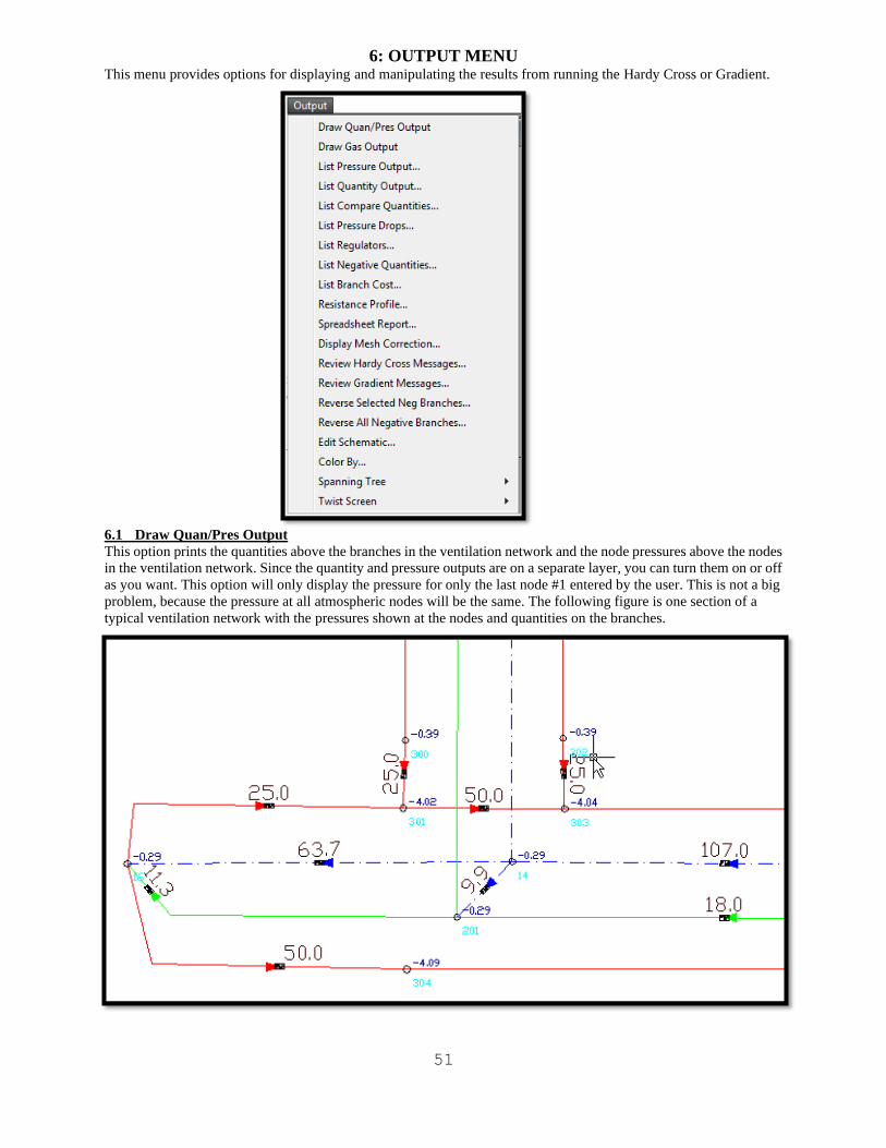
51
6: OUTPUT MENU This menu provides options for displaying and manipulating the results from running the Hardy Cross or Gradient.
6.1 Draw Quan/Pres Output
This option prints the quantities above the branches in the ventilation network and the node pressures above the nodes
in the ventilation network. Since the quantity and pressure outputs are on a separate layer, you can turn them on or off
as you want. This option will only display the pressure for only the last node #1 entered by the user. This is not a big
problem, because the pressure at all atmospheric nodes will be the same. The following figure is one section of a
typical ventilation network with the pressures shown at the nodes and quantities on the branches.
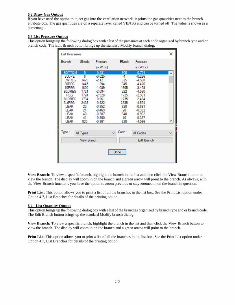
52
6.2 Draw Gas Output
If you have used the option to inject gas into the ventilation network, it prints the gas quantities next to the branch
attribute box. The gas quantities are on a separate layer called VENTG and can be turned off. The value is shown as a
percentage.
6.3 List Pressure Output
This option brings up the following dialog box with a list of the pressures at each node organized by branch type and or
branch code. The Edit Branch button brings up the standard Modify branch dialog.
View Branch: To view a specific branch, highlight the branch in the list and then click the View Branch button to
view the branch. The display will zoom in on the branch and a green arrow will point to the branch. As always, with
the View Branch functions you have the option to zoom previous or stay zoomed in on the branch in question.
Print List: This option allows you to print a list of all the branches in the list box. See the Print List option under
Option 4.7, List Branches for details of the printing option.
6.4 List Quantity Output
This option brings up the following dialog box with a list of the branches organized by branch type and or branch code.
The Edit Branch button brings up the standard Modify branch dialog.
View Branch: To view a specific branch, highlight the branch in the list and then click the View Branch button to
view the branch. The display will zoom in on the branch and a green arrow will point to the branch.
Print List: This option allows you to print a list of all the branches in the list box. See the Print List option under
Option 4.7, List Branches for details of the printing option.
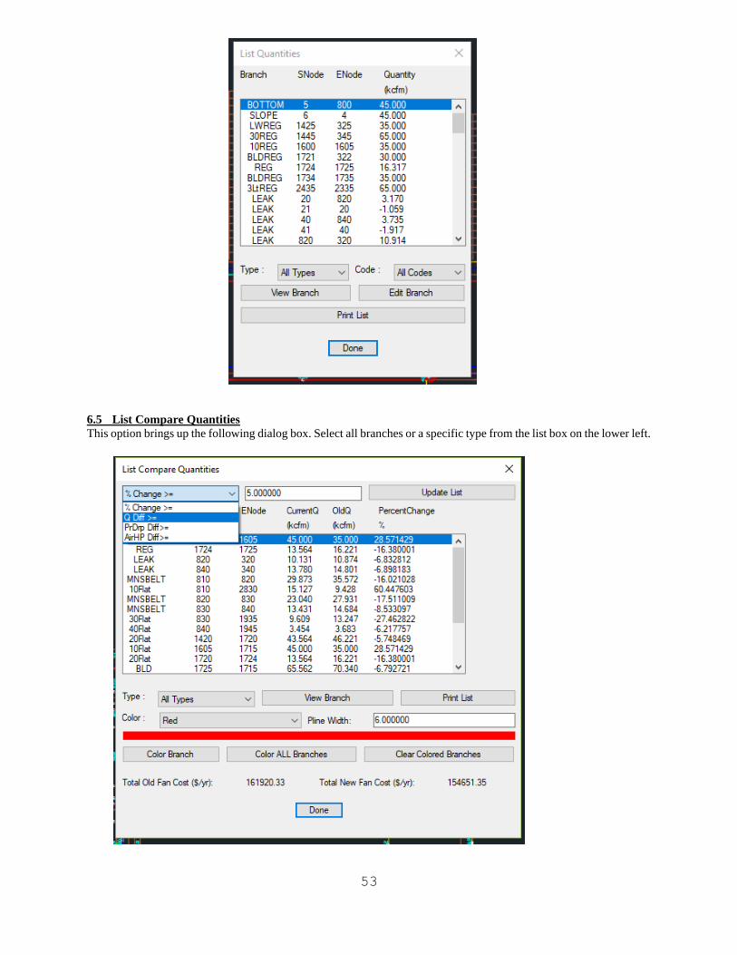
53
6.5 List Compare Quantities
This option brings up the following dialog box. Select all branches or a specific type from the list box on the lower left.
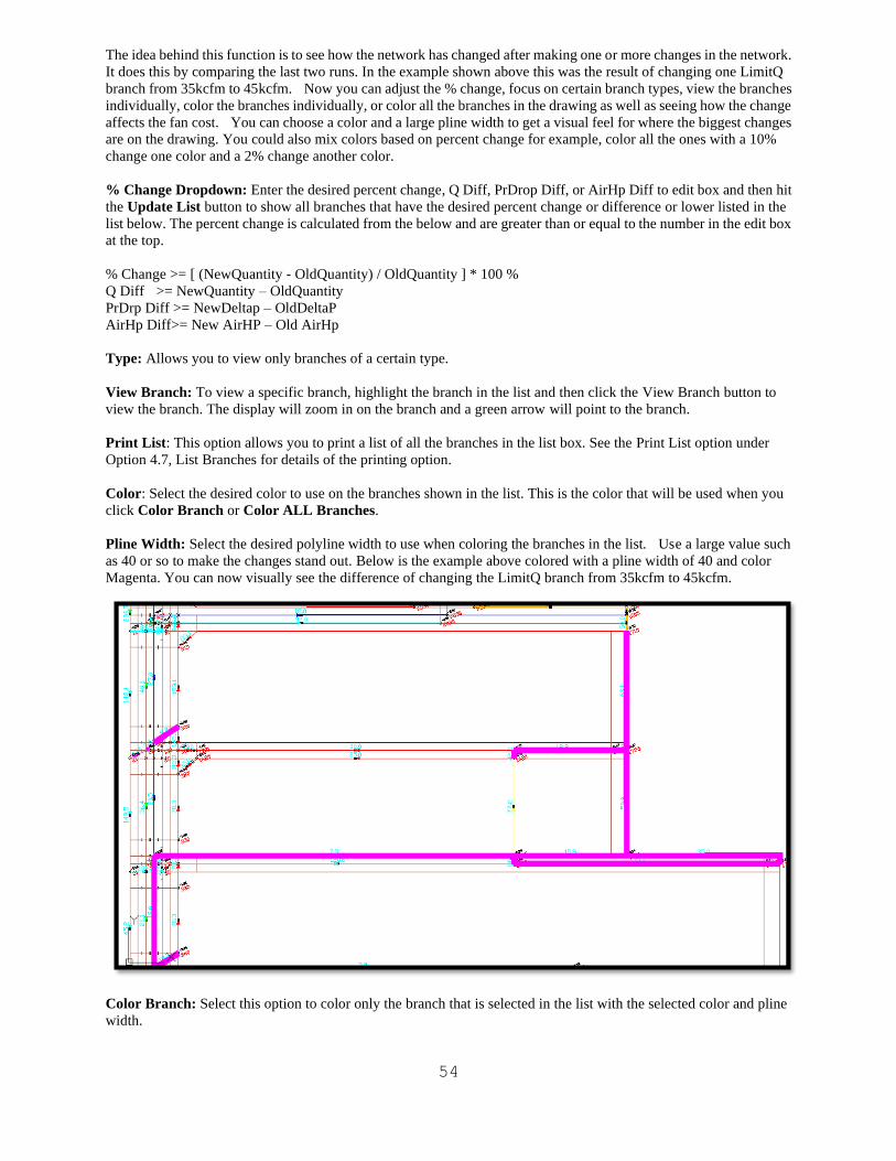
54
The idea behind this function is to see how the network has changed after making one or more changes in the network.
It does this by comparing the last two runs. In the example shown above this was the result of changing one LimitQ
branch from 35kcfm to 45kcfm. Now you can adjust the % change, focus on certain branch types, view the branches
individually, color the branches individually, or color all the branches in the drawing as well as seeing how the change
affects the fan cost. You can choose a color and a large pline width to get a visual feel for where the biggest changes
are on the drawing. You could also mix colors based on percent change for example, color all the ones with a 10%
change one color and a 2% change another color.
% Change Dropdown: Enter the desired percent change, Q Diff, PrDrop Diff, or AirHp Diff to edit box and then hit
the Update List button to show all branches that have the desired percent change or difference or lower listed in the
list below. The percent change is calculated from the below and are greater than or equal to the number in the edit box
at the top.
% Change >= [ (NewQuantity - OldQuantity) / OldQuantity ] * 100 %
Q Diff >= NewQuantity – OldQuantity
PrDrp Diff >= NewDeltap – OldDeltaP
AirHp Diff>= New AirHP – Old AirHp
Type: Allows you to view only branches of a certain type.
View Branch: To view a specific branch, highlight the branch in the list and then click the View Branch button to
view the branch. The display will zoom in on the branch and a green arrow will point to the branch.
Print List: This option allows you to print a list of all the branches in the list box. See the Print List option under
Option 4.7, List Branches for details of the printing option.
Color: Select the desired color to use on the branches shown in the list. This is the color that will be used when you
click Color Branch or Color ALL Branches.
Pline Width: Select the desired polyline width to use when coloring the branches in the list. Use a large value such
as 40 or so to make the changes stand out. Below is the example above colored with a pline width of 40 and color
Magenta. You can now visually see the difference of changing the LimitQ branch from 35kcfm to 45kcfm.
Color Branch: Select this option to color only the branch that is selected in the list with the selected color and pline
width.
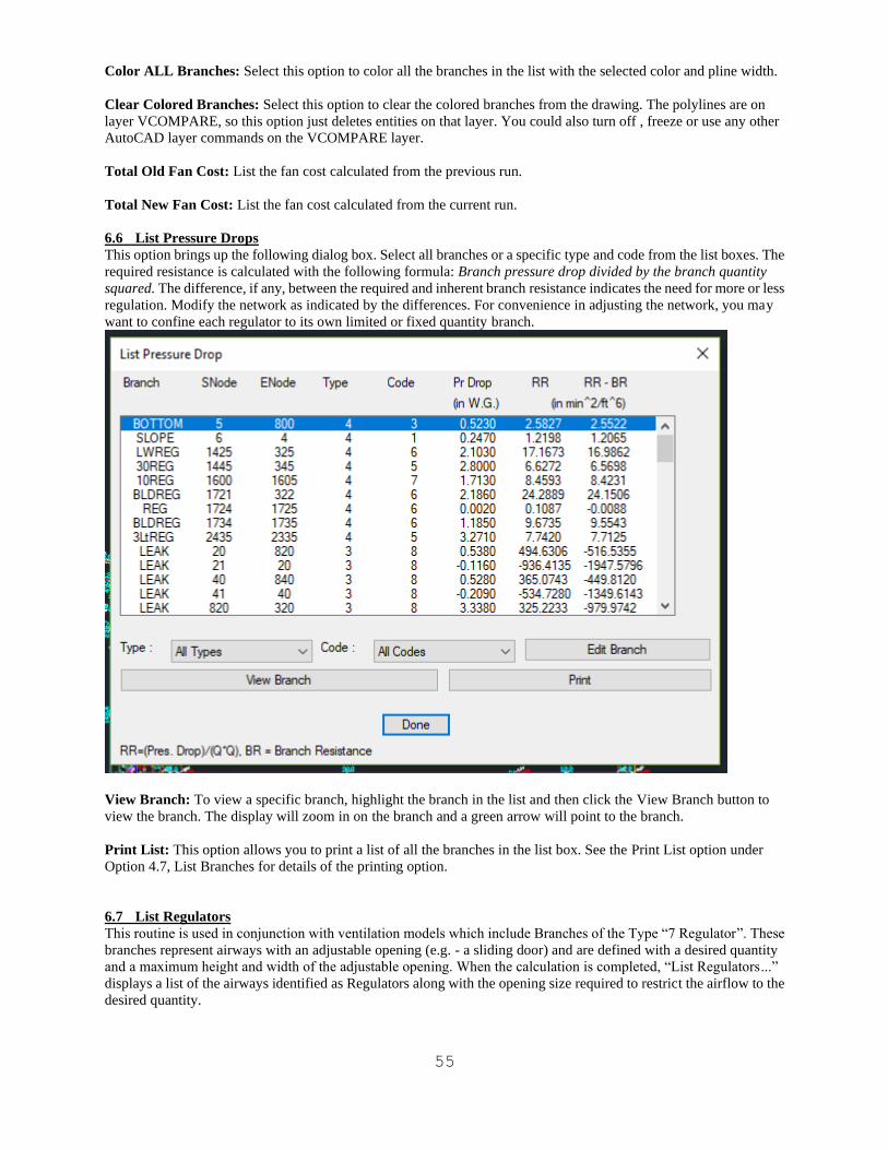
55
Color ALL Branches: Select this option to color all the branches in the list with the selected color and pline width.
Clear Colored Branches: Select this option to clear the colored branches from the drawing. The polylines are on
layer VCOMPARE, so this option just deletes entities on that layer. You could also turn off , freeze or use any other
AutoCAD layer commands on the VCOMPARE layer.
Total Old Fan Cost: List the fan cost calculated from the previous run.
Total New Fan Cost: List the fan cost calculated from the current run.
6.6 List Pressure Drops
This option brings up the following dialog box. Select all branches or a specific type and code from the list boxes. The
required resistance is calculated with the following formula: Branch pressure drop divided by the branch quantity
squared. The difference, if any, between the required and inherent branch resistance indicates the need for more or less
regulation. Modify the network as indicated by the differences. For convenience in adjusting the network, you may
want to confine each regulator to its own limited or fixed quantity branch.
View Branch: To view a specific branch, highlight the branch in the list and then click the View Branch button to
view the branch. The display will zoom in on the branch and a green arrow will point to the branch.
Print List: This option allows you to print a list of all the branches in the list box. See the Print List option under
Option 4.7, List Branches for details of the printing option.
6.7 List Regulators
This routine is used in conjunction with ventilation models which include Branches of the Type “7 Regulator”. These
branches represent airways with an adjustable opening (e.g. - a sliding door) and are defined with a desired quantity
and a maximum height and width of the adjustable opening. When the calculation is completed, “List Regulators...”
displays a list of the airways identified as Regulators along with the opening size required to restrict the airflow to the
desired quantity.
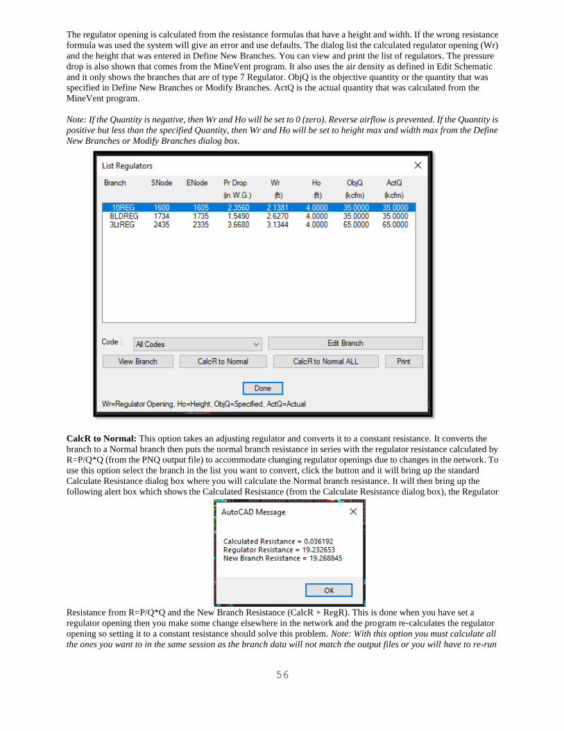
56
The regulator opening is calculated from the resistance formulas that have a height and width. If the wrong resistance
formula was used the system will give an error and use defaults. The dialog list the calculated regulator opening (Wr)
and the height that was entered in Define New Branches. You can view and print the list of regulators. The pressure
drop is also shown that comes from the MineVent program. It also uses the air density as defined in Edit Schematic
and it only shows the branches that are of type 7 Regulator. ObjQ is the objective quantity or the quantity that was
specified in Define New Branches or Modify Branches. ActQ is the actual quantity that was calculated from the
MineVent program.
Note: If the Quantity is negative, then Wr and Ho will be set to 0 (zero). Reverse airflow is prevented. If the Quantity is
positive but less than the specified Quantity, then Wr and Ho will be set to height max and width max from the Define
New Branches or Modify Branches dialog box.
CalcR to Normal: This option takes an adjusting regulator and converts it to a constant resistance. It converts the
branch to a Normal branch then puts the normal branch resistance in series with the regulator resistance calculated by
R=P/Q*Q (from the PNQ output file) to accommodate changing regulator openings due to changes in the network. To
use this option select the branch in the list you want to convert, click the button and it will bring up the standard
Calculate Resistance dialog box where you will calculate the Normal branch resistance. It will then bring up the
following alert box which shows the Calculated Resistance (from the Calculate Resistance dialog box), the Regulator
Resistance from R=P/Q*Q and the New Branch Resistance (CalcR + RegR). This is done when you have set a
regulator opening then you make some change elsewhere in the network and the program re-calculates the regulator
opening so setting it to a constant resistance should solve this problem. Note: With this option you must calculate all
the ones you want to in the same session as the branch data will not match the output files or you will have to re-run
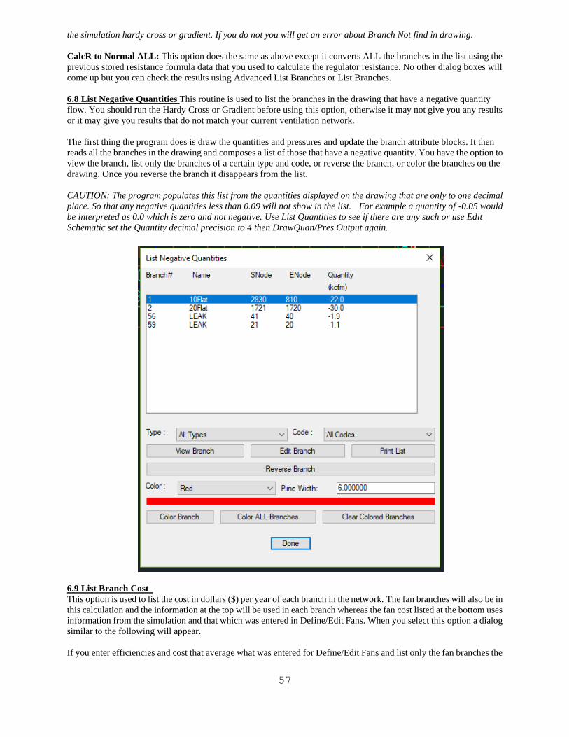
57
the simulation hardy cross or gradient. If you do not you will get an error about Branch Not find in drawing.
CalcR to Normal ALL: This option does the same as above except it converts ALL the branches in the list using the
previous stored resistance formula data that you used to calculate the regulator resistance. No other dialog boxes will
come up but you can check the results using Advanced List Branches or List Branches.
6.8 List Negative Quantities This routine is used to list the branches in the drawing that have a negative quantity
flow. You should run the Hardy Cross or Gradient before using this option, otherwise it may not give you any results
or it may give you results that do not match your current ventilation network.
The first thing the program does is draw the quantities and pressures and update the branch attribute blocks. It then
reads all the branches in the drawing and composes a list of those that have a negative quantity. You have the option to
view the branch, list only the branches of a certain type and code, or reverse the branch, or color the branches on the
drawing. Once you reverse the branch it disappears from the list.
CAUTION: The program populates this list from the quantities displayed on the drawing that are only to one decimal
place. So that any negative quantities less than 0.09 will not show in the list. For example a quantity of -0.05 would
be interpreted as 0.0 which is zero and not negative. Use List Quantities to see if there are any such or use Edit
Schematic set the Quantity decimal precision to 4 then DrawQuan/Pres Output again.
6.9 List Branch Cost
This option is used to list the cost in dollars ($) per year of each branch in the network. The fan branches will also be in
this calculation and the information at the top will be used in each branch whereas the fan cost listed at the bottom uses
information from the simulation and that which was entered in Define/Edit Fans. When you select this option a dialog
similar to the following will appear.
If you enter efficiencies and cost that average what was entered for Define/Edit Fans and list only the fan branches the

58
numbers should be close to the same. This option can be used to simulate the effects of changing the efficiencies and
cost and hitting Update List to see how the cost changes.
Average Efficiencies and Cost: These numbers should be an average of the fans in the system but can be any
numbers you would like to simulate.
Fan Cost: This is the cost computed after the simulation based on the operating point of the fan and the efficiencies
and cost that were entered in Define/Edit Fans.
Branch Cost: This is the total cost of the branches that ARE listed in the list above it based on the type chosen.
Type: Allows you to view only branches of a certain type. Notice that the Branch Cost will change so that it only totals
the branches in the list of the Type chosen.
Code: Allows you to view only branches of a certain code. Notice that the Branch Cost will change so that it only
totals the branches in the list of the Code chosen.
View Branch: To view a specific branch, highlight the branch in the list and then click the View Branch button to
view the branch. The display will zoom in on the branch and a green arrow will point to the branch.
Edit Branch: Allows you to edit the Branch Information and brings up the standard Modify Branch dialog.
Print List: This option allows you to print a list of all the branches in the list box. See the Print List option under
Option 4.7, List Branches for details of the printing option.
6.10 Resistance Profile
When you select this option the program draws the quantities and pressures, gathers the branch information and
displays the following dialog box.
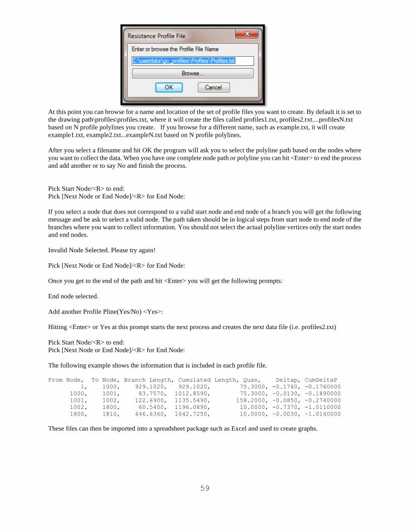
59
At this point you can browse for a name and location of the set of profile files you want to create. By default it is set to
the drawing path\profiles\profiles.txt, where it will create the files called profiles1.txt, profiles2.txt....profilesN.txt
based on N profile polylines you create. If you browse for a different name, such as example.txt, it will create
example1.txt, example2.txt...exampleN.txt based on N profile polylines.
After you select a filename and hit OK the program will ask you to select the polyline path based on the nodes where
you want to collect the data. When you have one complete node path or polyline you can hit <Enter> to end the process
and add another or to say No and finish the process.
Pick Start Node/<R> to end:
Pick [Next Node or End Node]/<R> for End Node:
If you select a node that does not correspond to a valid start node and end node of a branch you will get the following
message and be ask to select a valid node. The path taken should be in logical steps from start node to end node of the
branches where you want to collect information. You should not select the actual polyline vertices only the start nodes
and end nodes.
Invalid Node Selected. Please try again!
Pick [Next Node or End Node]/<R> for End Node:
Once you get to the end of the path and hit <Enter> you will get the following prompts:
End node selected.
Add another Profile Pline(Yes/No) <Yes>:
Hitting <Enter> or Yes at this prompt starts the next process and creates the next data file (i.e. profiles2.txt)
Pick Start Node/<R> to end:
Pick [Next Node or End Node]/<R> for End Node:
The following example shows the information that is included in each profile file.
From Node, To Node, Branch Length, Cumulated Length, Quan, Deltap, CumDeltaP
1, 1000, 929.1020, 929.1020, 75.3000, -0.1760, -0.1760000
1000, 1001, 83.7570, 1012.8590, 75.3000, -0.0130, -0.1890000
1001, 1002, 122.6900, 1135.5490, 158.2000, -0.0850, -0.2740000
1002, 1800, 60.5400, 1196.0890, 10.0000, -0.7370, -1.0110000
1800, 1810, 446.6360, 1642.7250, 10.0000, -0.0030, -1.0140000
These files can then be imported into a spreadsheet package such as Excel and used to create graphs.
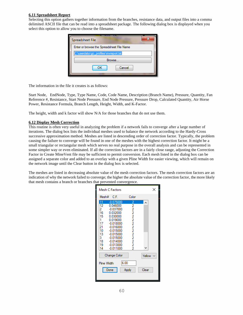
60
6.11 Spreadsheet Report
Selecting this option gathers together information from the branches, resistance data, and output files into a comma
delimited ASCII file that can be read into a spreadsheet package. The following dialog box is displayed when you
select this option to allow you to choose the filename.
The information in the file it creates is as follows:
Start Node, EndNode, Type, Type Name, Code, Code Name, Description (Branch Name), Pressure, Quantity, Fan
Reference #, Resistance, Start Node Pressure, End Node Pressure, Pressure Drop, Calculated Quantity, Air Horse
Power, Resistance Formula, Branch Length, Height, Width, and K-Factor.
The height, width and k factor will show N/A for those branches that do not use them.
6.12 Display Mesh Correction
This routine is often very useful in analyzing the problem if a network fails to converge after a large number of
iterations. The dialog box lists the individual meshes used to balance the network according to the Hardy-Cross
successive approximation method. Meshes are listed in descending order of correction factor. Typically, the problem
causing the failure to converge will be found in one of the meshes with the highest correction factor. It might be a
small triangular or rectangular mesh which serves no real purpose in the overall analysis and can be represented in
some simpler way or even eliminated. If all the correction factors are in a fairly close range, adjusting the Correction
Factor in Create MineVent file may be sufficient to permit conversion. Each mesh listed in the dialog box can be
assigned a separate color and added to an overlay with a given Pline Width for easier viewing, which will remain on
the network image until the Clear button in the dialog box is selected.
The meshes are listed in decreasing absolute value of the mesh correction factors. The mesh correction factors are an
indication of why the network failed to converge; the higher the absolute value of the correction factor, the more likely
that mesh contains a branch or branches that prevented convergence.
61
Since a network can have hundreds or thousands of branches, the problem branches are difficult to identify. To help
you identify such branches, use this option to highlight each mesh in the drawing starting with the mesh with the
largest correction factor. Only one mesh can be displayed at a time. The meshes are drawn with a dotted line; to help
make the selected mesh more visible, assign a color to each mesh that will contrast with the colors assigned to the
branches. The default color is yellow. Then select a mesh in the list and click the Apply button. The selected mesh will
appear as a dotted line in the color you assigned to the mesh and the branch percent correction factor for each branch in
the mesh will be posted below the branch’s attribute box. Use the Text Size in Drawing Configuration under the Set
Up pull down menu to adjust the text size for the branch correction factors. The resistance of branches with a high
percent correction factor frequently must be increased to achieve convergence.
The functions of the buttons in the dialog box are as follows.
Change Color: To change the color assigned to a mesh, highlight the mesh in the list, select a color from the pull
down list that will contrast with the branch colors; yellow is the default, and click the Change Color button.
Apply: To highlight a mesh in the drawing, highlight the mesh in the list and click the Apply button. The selected
mesh will be drawn with a dotted line in the color you assigned to that mesh. The correction factor for each branch in
the mesh will appear below the branch arrow. If a mesh is confined to a small region of the drawing, the display will
zoom to that area. You can zoom to read the mesh correction factors.
The branch or branches that are preventing convergence will likely have a large correction factor. Examine these
branches, paying special attention to the branch resistance. A branch with an exceptional low resistance may be
associated with a local short circuiting of the network flow. Check the resistance assigned to such branches.
Clear: Click this button to clear the mesh that was drawn on the drawing. This button deletes the layer VENTCF.
Done: Click this button to exit this option. Your mesh color assignments will be saved. If you did not hit Clear then the
mesh will still be highlighted on the drawing.
6.13 Review Hardy Cross Messages
This option reads from the Hardy Cross output file and displays information about the last simulation run. This is the
same information that is shown after you click the Run Hardy Cross button but it does not re-run the calculation. This
can save some time. However, if you make changes to the network you will want to re-run the calculation. The main
file accessed here is the PNQ file that is used for most of the options under the Output Menu. If the last run was
performed with the Gradient Method, which also creates a PNQ file then the program will tell you that the fan cost
calculations are from Gradient PNQ data. As long as the input data is treated the same the differences should be
negligible.
6.14 Review Gradient Messages
This option reads from the Gradient output file and displays information about the last simulation run. This is the same
information that is shown after you click the Run Gradient button but it does not re-run the calculation. This can save
some time. However, if you make changes to the network you will want to re-run the calculation. The main file
accessed here is the PNQ file that is used for most of the options under the Output Menu. The Gradient method does
not calculate the fan cost from the PNQ file but does so at a different place so it does not suffer from the same issue that
the Hardy Cross method.
CAUTION: If you make changes to the network and save without re-running the simulation then come back in and
select Review Gradient Method the branch identification numbers may not match. You should always run the Gradient
Method before this option if you have made changes to the drawing. The branch ID's are computed at the time the
program is run.
6.15 Reverse Selected Neg. Branches
After you run the MineVent program, the direction of flow may not agree with the direction you assigned to the branch
. In these cases the branch quantity will be negative. This option allows you to reverse the flow direction of selected
branches. When you select this option, the following command line prompt will appear.
Create a four sided polygon which contains the branches to reverse

62
The window can contain many branches, but only the branches with negative flow quantities will be affected. The
routine will change negative quantities to positive and reverse the direction of the arrow and the starting and ending
node sequence. The drawing is changed immediately and the .PEN input file, the .PNQ file and all other output files
will be updated next time you run Create MineVent File. If no other changes have been made to the drawing you do
not have to re-run Create MineVent File as it should give you the same result. The number of reversed branches is also
reported in an AutoCAD Alert box as shown in the following example.
6.16 Reverse All Negative Branches
After you run the MineVent program, the direction of flow may not agree with the direction you assigned to the
branch. In these cases the branch quantity will be negative. Use this option to reverse the direction of all the branches
in the drawing that have negative flow quantities. The routine will change negative quantities to positive and reverse
the direction of the arrow and the starting and ending node sequence. The drawing is changed immediately and the
.PEN input file, the .PNQ file and all other output files will be updated next time you run Create MineVent File. If no
other changes have been made to the drawing you do not have to re-run Create MineVent File as it should give you the
same result. The number of reversed branches is also reported in an AutoCAD Alert box as shown in the above
example.
6.17 Edit Schematic
When you select this option, the following dialog box appears. This option is used to change the size of pressures,
63
quantities, node numbers, names, arrows, %gas text and correction factor text. It is also used to set the defaults names
for the fan files and the CFG File (Branch code configuration files created from Configure Branches). The
information is stored with the drawing so that you can have one fan file and one CFG file for several different
scenarios. You can also change the position and orientation of the node numbers, pressures and quantities.
Size of New Nodes: This represents the size of the new nodes that have not yet been inserted. It does not affect the size
of existing nodes. It only applies to the node circle. The node number will be the size specified in Size of Node
Numbers below.
Size of Node Numbers: This represents the size, in drawing units, of the node numbers. This value is used for existing
nodes as well as upcoming nodes.
Size of Pressures: This represents the size, in drawing units, of the pressures. This value is used for existing pressures
as well as upcoming pressures.
Pressure Decimal Precision: You can set this to change the decimal precision of the pressures on the nodes from 1 to
4 digits then re-run Draw Quan/Pres Output to see the results.
Size of Branch Names: This represents the size, in drawing units, of the branch name. This value is only used for
existing branch names and does not apply to upcoming branch names, which will have a size of 1.
Size of Quantities: This represents the size, in drawing units, of the branch quantities. This value is used for existing
quantities as well as upcoming quantities.
Quantity Decimal Precision: You can set this to change the decimal precision of the quantities on the branches from
1 to 4 digits then re-run Draw Quan/Pres Output to see the results.
Size of Arrows: This represents the size, in drawing units, of the arrows. This value is used for existing arrows as well
as upcoming arrows.
Size of Gas: This represents the size, in drawing units, of the % Gas text. This value is used for existing gas text as
well as upcoming gas text.
Size of C.F. This represents the size, in drawing units, of the correction factors that are created when using Display
Mesh Correction. This value is used for existing C.F's as well as upcoming C.F.'s.
Move Attributes: This option automates the AutoCAD -Attedit command so that it defaults to moving text, one
attribute at a time. You can move quantities, pressures, node numbers, or any other text that is associated with an
attribute block. When you click this option, the following command line prompts appear.
Select Attribute:
After you select the attribute, the next prompt asks you to select the new location of the attribute.
Enter insertion point:
After you select the insertion point, the attribute will appear at the position you selected and the Edit
Schematic dialog box reappears.
Rotate Attribute: This option automates the AutoCAD -Attedit command rotate function. You can rotate quantities,
pressures, node numbers, or any other text that is associated with an attribute block. When you click this button, the
following command line prompts appear.
Select Attribute:
After you select the attribute, a construction line appears to indicate the orientation of the attribute. Orient the
construction line to the desired angle and click the left mouse button. The attribute will now appear at the
orientation you selected and the Edit Schematic dialog box reappears.
Note: If you get an error saying that more than one brand is defined you should run the hidden MineVent command
called DELBRAN and then re-run Edit Schematic.
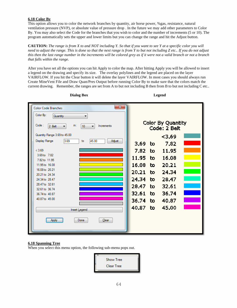
64
6.18 Color By
This option allows you to color the network branches by quantity, air horse power, %gas, resistance, natural
ventilation pressure (NVP), or absolute value of pressure drop . In the future we may add other parameters to Color
By. You may also select the Code for the branches that you wish to color and the number of increments (5 or 10). The
program automatically sets the upper and lower limits but you can change the range and hit the Adjust button.
CAUTION: The range is from X to and NOT including Y. So that if you want to see Y at a specific color you will
need to adjust the range. This is done so that the next range is from Y to but not including Z etc.. If you do not adjust
this then the last range number in the increments will be colored grey as if it were not a valid branch or not a branch
that falls within the range.
After you have set all the options you can hit Apply to color the map. After hitting Apply you will be allowed to insert
a legend on the drawing and specify its size. The overlay polylines and the legend are placed on the layer
VAIRFLOW. If you hit the Clear button it will delete the layer VAIRFLOW. In most cases you should always run
Create MineVent File and Draw Quan/Pres Output before running Color By to make sure that the colors match the
current drawing. Remember, the ranges are set from A to but not including B then from B to but not including C etc..
Dialog Box Legend
6.18 Spanning Tree
When you select this menu option, the following sub-menu pops out.
65
The Show Tree routine is used to display the network spanning trees in the event the program fails to execute due to
multiple trees. This error occurs because the calculation program is unable to construct a single network tree satisfying
the calculation algorithm, most often because of too many “Limit Quantity” branches. The display typically will show
one large connected network with a second smaller network common at some point. The topology problem is
somewhere in the smaller network, and can generally be eliminated by replacing the “Limit” quantity with a “Normal”
branch with an estimated (above average) resistance. The Clear Tree routine erases the colored network overlay
generated by Show Tree, allowing the overlay to remain on the image while the problem is being resolved. Note that
the data file used by Show Tree is not generated if a spanning tree problem does not exist.
6.19 Twist Screen:
Various methods of changing the angle of view without actually changing the coordinates to look at the network from
a different angle.
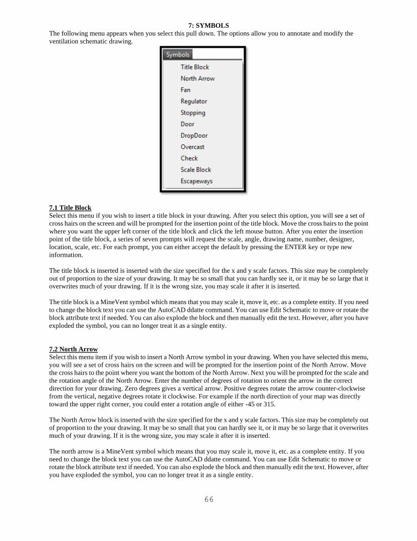
66
7: SYMBOLS
The following menu appears when you select this pull down. The options allow you to annotate and modify the
ventilation schematic drawing.
7.1 Title Block
Select this menu if you wish to insert a title block in your drawing. After you select this option, you will see a set of
cross hairs on the screen and will be prompted for the insertion point of the title block. Move the cross hairs to the point
where you want the upper left corner of the title block and click the left mouse button. After you enter the insertion
point of the title block, a series of seven prompts will request the scale, angle, drawing name, number, designer,
location, scale, etc. For each prompt, you can either accept the default by pressing the ENTER key or type new
information.
The title block is inserted is inserted with the size specified for the x and y scale factors. This size may be completely
out of proportion to the size of your drawing. It may be so small that you can hardly see it, or it may be so large that it
overwrites much of your drawing. If it is the wrong size, you may scale it after it is inserted.
The title block is a MineVent symbol which means that you may scale it, move it, etc. as a complete entity. If you need
to change the block text you can use the AutoCAD ddatte command. You can use Edit Schematic to move or rotate the
block attribute text if needed. You can also explode the block and then manually edit the text. However, after you have
exploded the symbol, you can no longer treat it as a single entity.
7.2 North Arrow
Select this menu item if you wish to insert a North Arrow symbol in your drawing. When you have selected this menu,
you will see a set of cross hairs on the screen and will be prompted for the insertion point of the North Arrow. Move
the cross hairs to the point where you want the bottom of the North Arrow. Next you will be prompted for the scale and
the rotation angle of the North Arrow. Enter the number of degrees of rotation to orient the arrow in the correct
direction for your drawing. Zero degrees gives a vertical arrow. Positive degrees rotate the arrow counter-clockwise
from the vertical, negative degrees rotate it clockwise. For example if the north direction of your map was directly
toward the upper right corner, you could enter a rotation angle of either -45 or 315.
The North Arrow block is inserted with the size specified for the x and y scale factors. This size may be completely out
of proportion to the your drawing. It may be so small that you can hardly see it, or it may be so large that it overwrites
much of your drawing. If it is the wrong size, you may scale it after it is inserted.
The north arrow is a MineVent symbol which means that you may scale it, move it, etc. as a complete entity. If you
need to change the block text you can use the AutoCAD ddatte command. You can use Edit Schematic to move or
rotate the block attribute text if needed. You can also explode the block and then manually edit the text. However, after
you have exploded the symbol, you can no longer treat it as a single entity.
67
7.3 Fan
This option will prompt you for the location (center of fan symbol) and outside diameter of the fan symbol. Key the
diameter but use the cursor to locate the symbol.
7.4 Regulator
This option will prompt you for the location (center of regulator symbol) and outside diameter of the regulator symbol.
Key the diameter but use the cursor to locate the symbol.
7.5 Stopping
This option will prompt you for the insertion point location (center of stopping symbol) , x and y scale factors and
rotation angle.
7.6 Door
This option will prompt you for the insertion point location (center of door symbol) , x and y scale factors and rotation
angle.
7.7 Drop Door
This option will prompt you for the insertion point location (center of drop door symbol) , x and y scale factors and
rotation angle.
7.8 Overcast
This option will prompt you for the insertion point location (center of overcast symbol) , x and y scale factors and
rotation angle.
7.9 Check
This option will prompt you for the insertion point location (center of check symbol) , x and y scale factors and
rotation angle.
7.10 Scale Block
This option allows you to change the map scale symbol. You will be prompted for the X and Y axis scale factors and
the angle through which to rotate the symbol. Next you enter the four dimensions of the scale legend. The dimensions
are multiplied by the scale factors to create the symbol.
7.11 Escapeways
This option will prompt you for the location (center of escapeway symbol) and outside diameter of the escapeway
symbol. Key the diameter but use the cursor to locate the symbol.
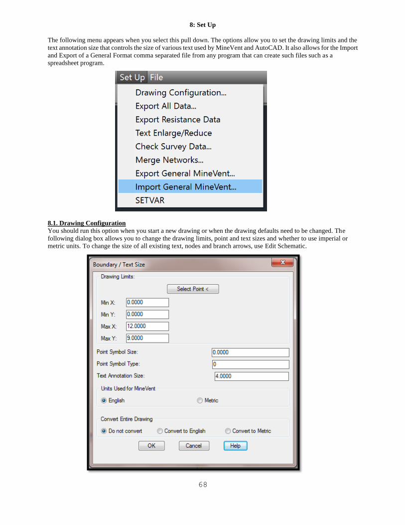
68
8: Set Up
The following menu appears when you select this pull down. The options allow you to set the drawing limits and the
text annotation size that controls the size of various text used by MineVent and AutoCAD. It also allows for the Import
and Export of a General Format comma separated file from any program that can create such files such as a
spreadsheet program.
8.1. Drawing Configuration
You should run this option when you start a new drawing or when the drawing defaults need to be changed. The
following dialog box allows you to change the drawing limits, point and text sizes and whether to use imperial or
metric units. To change the size of all existing text, nodes and branch arrows, use Edit Schematic.
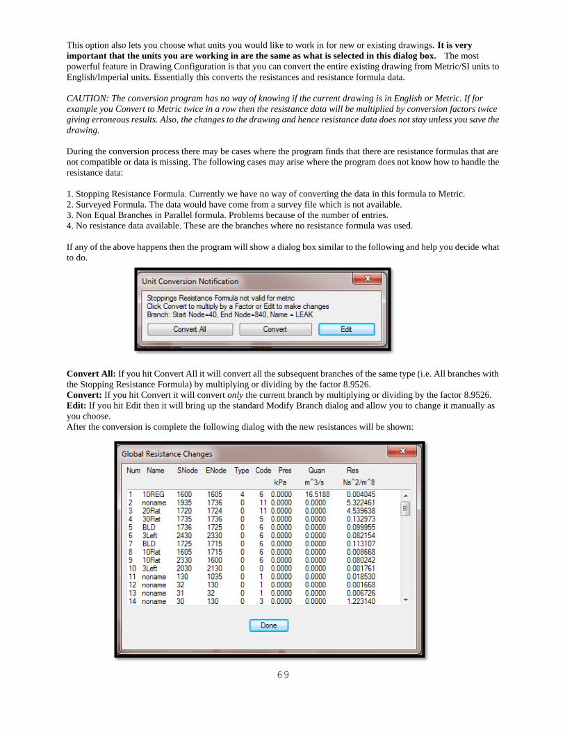
69
This option also lets you choose what units you would like to work in for new or existing drawings. It is very
important that the units you are working in are the same as what is selected in this dialog box. The most
powerful feature in Drawing Configuration is that you can convert the entire existing drawing from Metric/SI units to
English/Imperial units. Essentially this converts the resistances and resistance formula data.
CAUTION: The conversion program has no way of knowing if the current drawing is in English or Metric. If for
example you Convert to Metric twice in a row then the resistance data will be multiplied by conversion factors twice
giving erroneous results. Also, the changes to the drawing and hence resistance data does not stay unless you save the
drawing.
During the conversion process there may be cases where the program finds that there are resistance formulas that are
not compatible or data is missing. The following cases may arise where the program does not know how to handle the
resistance data:
1. Stopping Resistance Formula. Currently we have no way of converting the data in this formula to Metric.
2. Surveyed Formula. The data would have come from a survey file which is not available.
3. Non Equal Branches in Parallel formula. Problems because of the number of entries.
4. No resistance data available. These are the branches where no resistance formula was used.
If any of the above happens then the program will show a dialog box similar to the following and help you decide what
to do.
Convert All: If you hit Convert All it will convert all the subsequent branches of the same type (i.e. All branches with
the Stopping Resistance Formula) by multiplying or dividing by the factor 8.9526.
Convert: If you hit Convert it will convert only the current branch by multiplying or dividing by the factor 8.9526.
Edit: If you hit Edit then it will bring up the standard Modify Branch dialog and allow you to change it manually as
you choose.
After the conversion is complete the following dialog with the new resistances will be shown:
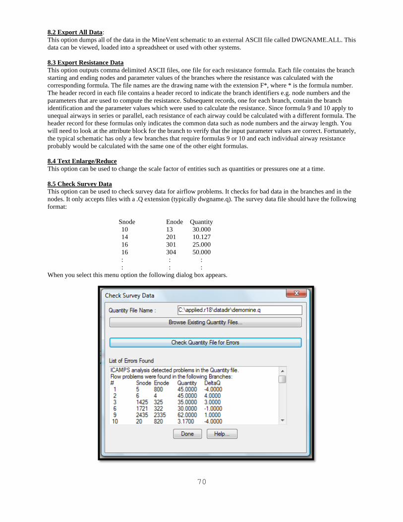
70
8.2 Export All Data:
This option dumps all of the data in the MineVent schematic to an external ASCII file called DWGNAME.ALL. This
data can be viewed, loaded into a spreadsheet or used with other systems.
8.3 Export Resistance Data
This option outputs comma delimited ASCII files, one file for each resistance formula. Each file contains the branch
starting and ending nodes and parameter values of the branches where the resistance was calculated with the
corresponding formula. The file names are the drawing name with the extension F*, where * is the formula number.
The header record in each file contains a header record to indicate the branch identifiers e.g. node numbers and the
parameters that are used to compute the resistance. Subsequent records, one for each branch, contain the branch
identification and the parameter values which were used to calculate the resistance. Since formula 9 and 10 apply to
unequal airways in series or parallel, each resistance of each airway could be calculated with a different formula. The
header record for these formulas only indicates the common data such as node numbers and the airway length. You
will need to look at the attribute block for the branch to verify that the input parameter values are correct. Fortunately,
the typical schematic has only a few branches that require formulas 9 or 10 and each individual airway resistance
probably would be calculated with the same one of the other eight formulas.
8.4 Text Enlarge/Reduce
This option can be used to change the scale factor of entities such as quantities or pressures one at a time.
8.5 Check Survey Data
This option can be used to check survey data for airflow problems. It checks for bad data in the branches and in the
nodes. It only accepts files with a .Q extension (typically dwgname.q). The survey data file should have the following
format:
Snode Enode Quantity
10 13 30.000
14 201 10.127
16 301 25.000
16 304 50.000
: : :
: : :
When you select this menu option the following dialog box appears.
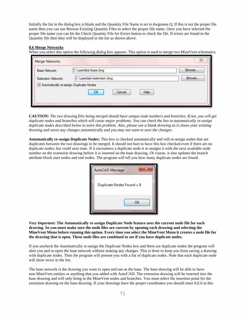
71
Initially the list in the dialog box is blank and the Quantity File Name is set to dwgname.Q. If this is not the proper file
name then you can use Browse Existing Quantity Files to select the proper file name. Once you have selected the
proper file name you can hit the Check Quantity File for Errors button to check the file. If errors are found in the
Quantity file then they will be displayed in the list as shown above.
8.6 Merge Networks
When you select this option the following dialog box appears. This option is used to merge two MineVent schematics.
CAUTION: The two drawing files being merged should have unique node numbers and branches. If not, you will get
duplicate nodes and branches which will cause major problems. You can check the box to automatically re-assign
duplicate nodes described below to solve this problem. Also, please use a blank drawing as it closes your existing
drawing and saves any changes automatically and you may not want to save the changes.
Automatically re-assign Duplicate Nodes: This box is checked automatically and will re-assign nodes that are
duplicates between the two drawings to be merged. It should not hurt to have this box checked even if there are no
duplicate nodes, but could save time. If it encounters a duplicate node it re-assigns it with the next available node
number on the extension drawing before it is inserted on the base drawing. Of course, it also updates the branch
attribute block start nodes and end nodes. The program will tell you how many duplicate nodes are found:
Very Important: The Automatically re-assign Duplicate Node feature uses the current node file for each
drawing. So you must make sure the node files are current by opening each drawing and selecting the
MineVent Menu before running this option. Every time you select the MineVent Menu it creates a node file for
the drawing that is open. These node files are combined to see if you have duplicate nodes.
If you uncheck the Automatically re-assign the Duplicate Nodes box and there are duplicate nodes the program will
alert you and re-open the base network without making any changes. This is done to keep you from saving a drawing
with duplicate nodes. Then the program will present you with a list of duplicate nodes. Note that each duplicate node
will show twice in the list.
The base network is the drawing you want to open and use as the base. The base drawing will be able to have
non-MineVent entities or anything that you added with AutoCAD. The extension drawing will be inserted into the
base drawing and will only bring in the MineVent nodes and branches. You must select the insertion point for the
extension drawing on the base drawing. If your drawings have the proper coordinates you should enter 0,0,0 at this
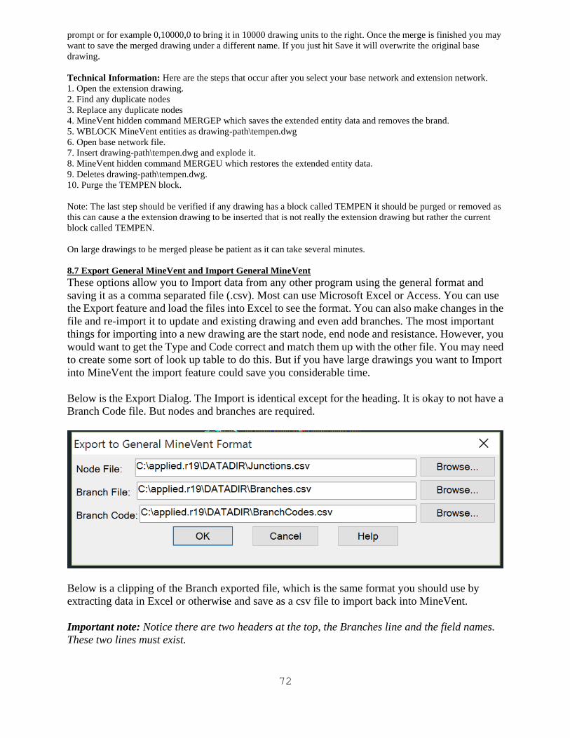
72
prompt or for example 0,10000,0 to bring it in 10000 drawing units to the right. Once the merge is finished you may
want to save the merged drawing under a different name. If you just hit Save it will overwrite the original base
drawing.
Technical Information: Here are the steps that occur after you select your base network and extension network.
1. Open the extension drawing.
2. Find any duplicate nodes
3. Replace any duplicate nodes
4. MineVent hidden command MERGEP which saves the extended entity data and removes the brand.
5. WBLOCK MineVent entities as drawing-path\tempen.dwg
6. Open base network file.
7. Insert drawing-path\tempen.dwg and explode it.
8. MineVent hidden command MERGEU which restores the extended entity data.
9. Deletes drawing-path\tempen.dwg.
10. Purge the TEMPEN block.
Note: The last step should be verified if any drawing has a block called TEMPEN it should be purged or removed as
this can cause a the extension drawing to be inserted that is not really the extension drawing but rather the current
block called TEMPEN.
On large drawings to be merged please be patient as it can take several minutes.
8.7 Export General MineVent and Import General MineVent
These options allow you to Import data from any other program using the general format and
saving it as a comma separated file (.csv). Most can use Microsoft Excel or Access. You can use
the Export feature and load the files into Excel to see the format. You can also make changes in the
file and re-import it to update and existing drawing and even add branches. The most important
things for importing into a new drawing are the start node, end node and resistance. However, you
would want to get the Type and Code correct and match them up with the other file. You may need
to create some sort of look up table to do this. But if you have large drawings you want to Import
into MineVent the import feature could save you considerable time.
Below is the Export Dialog. The Import is identical except for the heading. It is okay to not have a
Branch Code file. But nodes and branches are required.
Below is a clipping of the Branch exported file, which is the same format you should use by
extracting data in Excel or otherwise and save as a csv file to import back into MineVent.
Important note: Notice there are two headers at the top, the Branches line and the field names.
These two lines must exist.
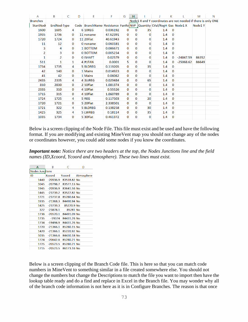
73
Below is a screen clipping of the Node File. This file must exist and be used and have the following
format. If you are modifying and existing MineVent map you should not change any of the nodes
or coordinates however, you could add some nodes if you know the coordinates.
Important note: Notice there are two headers at the top, the Nodes Junctions line and the field
names (ID,Xcoord, Ycoord and Atmosphere). These two lines must exist.
Below is a screen clipping of the Branch Code file. This is here so that you can match code
numbers in MineVent to something similar in a file created somewhere else. You should not
change the numbers but change the Descriptions to match the file you want to import then have the
lookup table ready and do a find and replace in Excel in the Branch file. You may wonder why all
of the branch code information is not here as it is in Configure Branches. The reason is that once

74
you match the number to a description it is much easier just to open Configure Branches and make
the rest of the changes.
Final note: Use the new Import/Export feature with caution. It will update all branches in an
existing drawing which could take time. Not to mention the feedback we get from industry usually
says it is better to make changes graphically instead of in some table view. These functions were
initially intended to be used if you have data already in table view and want to import it into
MineVent.
8.8 Import CONSOL Minimal comma separated data
The hidden command IMPORTCON. When you type in this hidden command at the MineVent/AutoCAD command
prompt the following dialog box appears similar to the General Import format dialog only the header is different and
the DATA FORMAT IS DIFFERENT. Note you must have MineVent loaded or select it from the STARTUP menu.
This is a more simplified format to extract from the CONSOL ventilation program which uses a Microsoft Access file
(.MDB). You must load the .MDB file into Microsoft Access and create a comma separated file with the following
formats below:
Note: You could use the General Import and Export and format the CONSOL file in Access to match the General
Import format above. The below is easier but has less data as of current the only thing used is the snode, enode,
Type (actually matches to the branch code file), and resistance is used. Quantity and Pressure (NVP) is set to 0.0. If
you want to use the others then use the General Format and add the extra data.
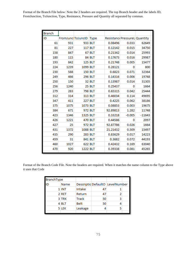
75
Format of the Branch File below: Note the 2 headers are required. The top Branch header and the labels ID,
FromJunction, ToJunction, Type, Resistance, Pressure and Quantity all separated by commas.
Format of the Branch Code File. Note the headers are required. When it matches the name column to the Type above
it uses that Code
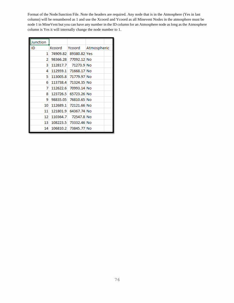
76
Format of the Node/Junction File. Note the headers are required. Any node that is in the Atmosphere (Yes in last
column) will be renumbered as 1 and use the Xcoord and Ycoord as all Minevent Nodes in the atmosphere must be
node 1 in MineVent but you can have any number in the ID column for an Atmosphere node as long as the Atmosphere
column is Yes it will internally change the node number to 1.
77
INDEX
A
arrow · 18, 20, 21, 22, 25, 44, 46, 47, 50, 52, 57 branch flow · 18 direction · 53 find · 10, 18, 25, 44, 46, 50 flow direction · 53
atmospheric node · 5, 9, 16, 36 AUTOCAD COMMAND ABBREVIATIONS IN MINEVENT · 4 AutoCAD commands · 6 AutoCAD erase command · 3, 10, 21
B
Branch · 6, 15, 16, 17, 18, 19, 20, 21, 23, 31, 35, 44, 46, 47, 50 attribute blocks · 25 between the same two nodes · 23 Calculate Resistance · 17 code · 16, 24 color · 18 color, linetype and defaults · 28 copy · 22 defining · 15 duplicate · 23 edit · 25 erase · 21 fan · 16 finding nodes · 31 k-factor · 25, 29 length · 18 list · 24 maximum · 15 menu · 15 merge · 21, 25 modify · 18, 19 moving · 10, 21 name · 16 nodes · 16, 17 parallel · 18, 23, 40 print list · 26 quantities · 18 quantity · 16 resistance · 16 reverse · 20, 25 showing · 24 split · 20, 25 code · 29 type · 16, 24 type · 44 update · 25 view · 18, 25, 44 writing file · 31
Branch Code Cosmetics color and linetype · 28
Branch Code-Description · 28
78
C
Calculate R · 17 Check Survey Data · 61 Code Defaults · 17, 28 Color By · 6, 55
quantity;air HP;gas;resistance · 55 range · 55
Config File · 28 default · 54
Configure Branches · 16, 17, 18, 28, 29, 54 correction factor · 5, 36, 39, 40, 41, 51, 52, 54 Create Penn File · 36
D
Define/Edit Fans · 32 DELBRAN · 55 Digitize/Enter Nodes · 9 digitizer · 2, 3, 9 Display menu · 8 Display Mesh Correction · 40, 51
color · 52 Draw Gas · 44 Draw Quan/Pres · 18, 23, 43 Drawing Configuration · 59 drawing limits · 59 dummy
branches · 5, 16 nodes · 9
duplicate branches · 23 nodes · 9
E
Edit menu · 7 Edit Schematic · 10, 32, 36, 40, 48, 54, 55, 57, 59 ERASBH · 25 Escapeways · 58 Export All Data · 61 Export Resistance Data · 61
F
fan · 5, 6, 16, 19, 27, 32, 33, 34, 35, 36, 37, 39, 40, 58 blade setting · 27, 33 Branch · 5 create new · 33 curve · 32, 39 data · 33 default file · 54 define/edit · 27, 32 deleting · 35 eq parallel · 34 eq series · 34 list · 27, 35
79
load · 33 model or description · 33 modify curve · 33 new curve · 33 operating range · 39 option · 33 pairs · 33 pressures · 33 quantities · 33 reference number · 27, 33, 35 type · 33 uneq parallel · 34 uneq series · 34
Find Isolated Node · 31 fixed quantity · 5, 20, 37, 39, 40, 47
G
gas draw · 44 injection · 5, 16, 44
Global Resistance Change · 29, 30
H
Hardy-Cross · 51 Hidden MineVent Commands
DELBRAN · 55 ERASEBH · 25 MERGEP · 63 MERGEU · 63
I
isolated nodes · 31, 37 Iterations · 36
K
K Factor · 25, 29, 30 global change · 30
L
Levels defining · 14 elevation · 13 Multiple · 13 switching · 14
limited quantity · 20 List Pressure · 44 List Pressure Drops · 5, 45, 47 List Quantity · 44 List Regulators · 47 List Unused Nodes · 9, 11, 12
80
M
Merge Networks · 62 MERGEP · 63 MERGEU · 63 MineSimU and MineWater · 2 MineVent Menu · 6 Modify Branch Parameters · 25 moving
quantities;pressures · 55
N
Node · 3, 6, 7, 9, 10, 11, 13, 16, 20, 23, 31, 36, 54 Node Menu · 9 nodes
copying · 23 duplicates · 11, 22, 23 erasing · 10 finding · 10 listing · 11 moving · 10 reading from file · 13 viewing · 11
North Arrow · 57 Numerical Branch Code Data
resistance defaults · 28 NVP · 5, 16, 19, 55
O
Osnaps · 3 Output · 6, 10, 20, 31, 32, 36, 37, 40, 43, 55 Output Menu · 43
P
Penn State Ventilation program · 36, 53 analysis · 39 atmospheric node · 36 convergence · 38, 39, 51, 52 correction factor · 36, 41 fan file · 36, 40 files · 39, 53 flow · 53 iterations · 40 maximum iterations · 36, 41 running from command prompt · 37
PenVent · 5, 18, 20, 23, 32 Pressure Files · 18 Print · 14, 26, 44, 46, 47, 50
header · 26 LPT1 · 26
Printer port and networking · 26 set-up · 26
81
Q
Quantity · 6, 16, 19, 23, 31, 44, 48, 56, 61, 62 file · 61
Quantity Files · 18
R
Read Node File · 3, 13 Regulators · 5, 6, 16, 19, 47, 48, 58
Wr and Ho · 48 resistance · 5, 15, 16, 17, 18, 20, 21, 24, 25, 28, 29, 30, 40, 47, 52, 55, 56, 61
calculation · 28 formulas · 17, 25 global change · 29 minimum · 18 non-equal branches · 18 RR and BR · 47
Reverse All Negative Branches · 53 Reverse Selected Negative Branches · 53 Review Network Messages · 52, 53 rotating
quantities;pressures · 55 Run PSU/MVS · 31, 36, 52, 53
S
Scale Block · 58 Seams
Multiple · 13 Single Document Interface (SDI) · 3 size
arrows · 55 branch names · 54 correction factor · 55 pressures;quantities;node numbers;names;arrows;gas · 54 gas · 55 new nodes · 54 node numbers · 54 pressures · 54 quantities · 54
Spanning Tree Clear/Hide · 56 show · 56
Startup menu · 2 surveyed data · 17 Symbols · 57
T
Text Enlarge/Reduce · 61 Title Block · 6, 57 Tools menu · 7
82
V
VENTCODE.CFG · 28 View Branch · 18, 25, 44, 46, 47, 50
Z
Z coordinates · 11 z-value · 3