mine surveying compile
TRANSCRIPT
8/3/2019 Mine Surveying Compile
http://slidepdf.com/reader/full/mine-surveying-compile 1/31
MINE SURVEYING
INTRODUCTION TO THE IMPORTANCE OF MINE SURVEYING
Mine survey is part of mining science and technology that deals with measurement on the
surface and in the earth crust, during exploration, exploitation of minerals andconstruction of mining plants. It includes all measurements, calculations and mapping
which serve the purpose of ascertaining and documenting information at all stages from
prospecting to exploitation and utilizing mineral deposits both by surface and
underground working. The results of mine surveys are then used for the plotting of plans
conditions of deposits and also for the solution of various problems of the mining
geometry.
The principal tasks of mine- surveying include;
(1) The interpretation of the geology of mineral deposits in relation to the economic
exploitation thereof
(2) The investigation and negotiation of mineral mining rights
(3) Making and recording, and calculations of mine surveying measurements
(4) Mining cartography
(5)
Investigation and prediction of effects of mine working on the surface andunderground strata
(6) Mine planning in the context of local environment and subsequent rehabilitation
(7) The location, structure, configuration, dimensions and characteristics of the
mineral deposits and of the adjoining rocks and overlying strata. The assessment
of mineral reserves and the economics of their exploitation.
Other mine surveying activities include:
a) The acquisition, sale, lease and management of mineral properties.
b) Providing the basis of the planning, direction and control of mine workings to ensure
economical and safe mining operations.
8/3/2019 Mine Surveying Compile
http://slidepdf.com/reader/full/mine-surveying-compile 2/31
c) The study of rock and ground movements caused by mining operations, their
prediction, and the precautions and remedial treatment of subsidence damage.
d) Assisting in planning and rehabilitation of land affected by mineral operations and
collaborating with local government planning authorities.
Nevertheless, mine surveyors have to participate in all stages of the operation of mining
plants from the exploration of a mineral deposit and up to the abandonment of a mine
after it has been worked out, and to perform specific survey work at all these stages;
(a) Exploration of mineral deposits: the mine surveyor make land surveys, the determine
and transfers into nature the positions of exploring workings (pits , ditches etc) makes
the surveys of exploring workings assaying points, seams outcrops, bedding elementsof mineral deposits and enclosing rock, and complies the graphical documentation
representing the shape and bedding conditions of a deposit. Mine-surveying plans and
sections plotted by the results of geological prospecting are used for the calculations
of mineral reserve and design of mining plant.
(b) Design and construction of mining plant the mine surveyor participates in
construction surveying; the determination of the boundaries of mine field according
to the current regulations on land allotment; design of working systems and surface
structures; development of measures for the protection of surface and underground
structures against harmful influence of underground working; compilation of the
graphs of work organization and plans of mining work for the periods of construction
and exploitation of a mining plant; and the calculation of the losses and industrial
reserves of minerals.
(c) Exploitation of deposits: the role of the mine surveyor at the stage of exploitation is
extremely important and includes the following operation; surveying of workings;
assigning of directions to working; compilation of plans by the results of surveys;
control of the mining work in accordance with the design specifications and safety
regulations; reclamation of land planning of the preparatory and stopping mining

8/3/2019 Mine Surveying Compile
http://slidepdf.com/reader/full/mine-surveying-compile 3/31
work, calculation of the balance and industrial reserves, losses and dilution of
minerals.
The Mine Surveyor is one of the key contributors to the welfare of the mining industry.
They are responsible for maintaining an accurate plan of the mine as a whole and will
update maps of the surface layout to account for new buildings and other structures, as
well as surveying the underground mine workings in order to keep a record of the mining
operation.
More importantly, the surveyor is involved in the measuring process to calculate ore
production, in volume or mass units, from the mining operation. In addition to calculation
of ore production from the mining operation, the volume of the dumps of waste
accumulating on the surface of the mining property will also be surveyed. This aspect of
the work has turned the mine surveyor into a manager of the µresources¶ of the mine.
SURVEYING TOOLS
PLANS
These are drawings of orthogonal projections of objects onto a horizontal plane. They are
widely used for the representation of the Earth¶s surface and mining workings. Survey
plans usually contain the elevation marks (height coordinates) of particular points or are
constructed in isohypses; in the latter case, they are essentially projections with numerical
data.
MAPS:
These are representations of a geographic area, usually a portion of the earth's surface,drawn or printed on a flat surface. In most instances a map is a diagrammatic rather than
a pictorial representation of the terrain; it usually contains a number of generally accepted
symbols, which indicate the various natural, artificial, or cultural, features of the area it
covers. The basic type of map used to represent land areas is the topographic map. Such

8/3/2019 Mine Surveying Compile
http://slidepdf.com/reader/full/mine-surveying-compile 4/31
maps show the natural features of the area covered as well as certain artificial features,
known as cultural features. Political boundaries, such as the limits of towns, countries,
and states, are also shown. Because of the great variety of information included on them,
topographic maps are most often used as general reference maps. A topographic map is atype of map characterized by large-scale detail and quantitative representation of relief,
usually using contour lines in modern mapping, but historically using a variety of
methods. Traditional definitions require a topographic map to show both natural and
man-made features. A topographic map is typically published as a map series, made up of
two or more map sheets that combine to form the whole map. A contour line is a
combination of two line segments that connect but do not intersect; these represent
elevation on a topographic map.
Basic elements of a map
Geographic Grid: In order to locate a feature on a map or to describe the extent of an
area, it is necessary to refer to the map's geographic grid. This grid is made up of
meridians of longitude and parallels of latitude. By agreed convention, longitude is
marked 180° east and 180° west from 0° at Greenwich, England. Latitude is marked 90°
north and 90° south from the 0° parallel of the equator. Points on a map can be accurately
defined by giving degrees, minutes, and seconds for both latitude and longitude. Maps are
usually arranged so that true north is at the top of the sheet, and are provided with a
compass rose or some other indication of magnetic variation.
Scale: The scale to which a map is drawn represents the ratio of the distance between two
points on the earth and the distance between the two corresponding points on the map.
The scale is commonly represented in figures, as 1:100,000, which means that one unit
measured on the map (say 1 cm) represents 100,000 of the same units on the earth's
surface.
Objects are depicted in mine-surveying plans by diminishing the results of natural
measurements. The degree of diminution of a line in a plan is determined by the scale i.e
a dimension less fractional number in which the numerator is unity and the denominator

8/3/2019 Mine Surveying Compile
http://slidepdf.com/reader/full/mine-surveying-compile 5/31
shows how many time a line depicted in the plan can be laid off along the corresponding
horizontal distance in the terrain. This is what is called the numerical scale is what is
called the numerical scale of length, or simply numerical scale.
Consequently, S = 1/M where M is the denominator of the numerical scale.
In plans, numerical scales are written as simple fractions, for example;
1/500,1/1000.1/2000,1/10,000 etc.
The larger the denominator, the smaller the scale. For instance, if the horizontal
distance of a line on the terrain is equal to 174.30m and the scale of plan is 1/2000, the
length of the corresponding line on the plan will be 174.3:20= 8.71 cm; if a line on a
plan made on a scale 1/5000 is equal to 10.2cm the horizontal distance on the terrain
corresponding to that line will be 10.2 x50 = 510m.
SECTIONS
Sections are the representation of the details of an object, which are located in a certain
section plane. In mine surveying practice, the most common types of sections are
geological sections and sections of mining workings which depict the enclosing rock,
some details of a working, supports and other objects. In sections, objects and details may
be projected onto vertical, horizontal or inclined planes.
PROFILES
Profiles are graphs depicting, in a vertical section, only the contour or part of the contour
of an object considered, for instance, the terrain relief, rocks in the roof or foot of a
working, haulage tracks, etc.
8/3/2019 Mine Surveying Compile
http://slidepdf.com/reader/full/mine-surveying-compile 6/31
PROJECTIONS
These are graphical representations of particular spatial objects on the plane of drawings.
In mine surveying, orthogonal projections are preferably used, especially their variety
projections with numerical data.Orthogonal projections may be made on horizontal, vertical or inclined planes for more
clear representation, axonometric and affine projections are also employed.
SKETCHES
They are rough drawing of objects which are made by hand i.e without the use of rulers
and other drawing instruments. For instance, a mine survey makes sketches in the field
book when carrying out instrumental survey or taping of mining workings, measuring the
reserves of a mineral in store etc.
CLASSIFICATION OF DRAWINGS AND RULE OF MAPPING
As regards their compilation, all mine surveying drawings can be divided into
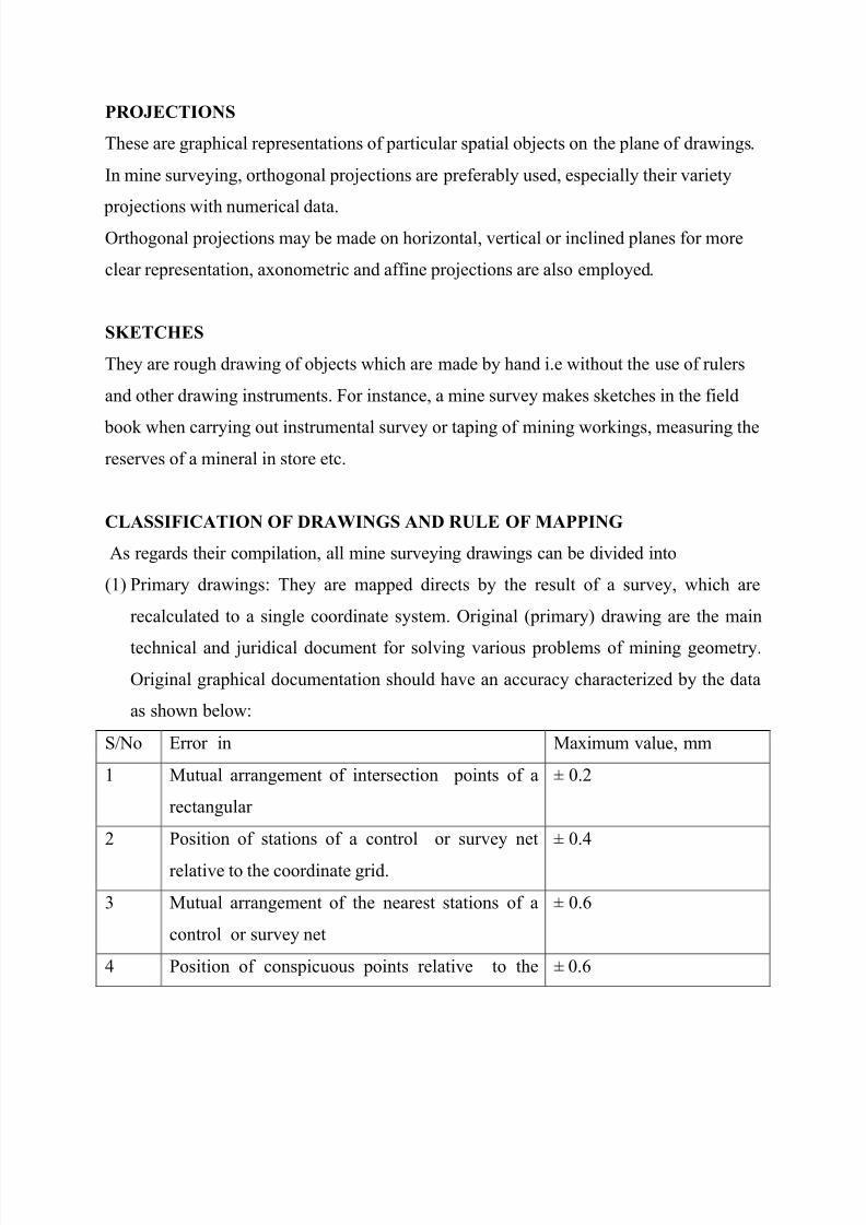
(1) Primary drawings: They are mapped directs by the result of a survey, which are
recalculated to a single coordinate system. Original (primary) drawing are the main
technical and juridical document for solving various problems of mining geometry.
Original graphical documentation should have an accuracy characterized by the data
as shown below:
S/No Error in Maximum value, mm
1 Mutual arrangement of intersection points of a
rectangular
± 0.2
2 Position of stations of a control or survey net
relative to the coordinate grid.
± 0.4
3 Mutual arrangement of the nearest stations of a
control or survey net
± 0.6
4 Position of conspicuous points relative to the ± 0.6

8/3/2019 Mine Surveying Compile
http://slidepdf.com/reader/full/mine-surveying-compile 7/31
nearest stations of a control or survey net
5 Mutual arrangement of the nearest conspicuous
points.
± 0.8
2. Secondary drawings are prepared by reproducing (copying) the original drawing.
They must be complemented and correct when a need arises and can be used for
various practical purposes, for instance for the compilations of exchange and calendar
plans of mining work development, special plans for accounting the reserves, mines stock
and loss of a mineral, plans of mine ventilation, plan for the prevention of accidents, etc.
The main requirements of secondary graphical documents are that they should contain all
the essential information as refigured by the purpose and that this information should be
drawn clearly.
Graphical documentation should preferably be drawn on the scales;
1/500,1/1000,1/2000,1/50,00 or 1/10,00; the scale 1/25,000 is recommended for
cartograms and general charts, and scales 1/5.1/10/1/20,1/50,1/100 and 1/200 , for small
objects.
Processes and materials for reproduction of mining graphical documentation.
The principal processes for the reproduction of drawings of mining graphical
documentation are diazotpe copying, electrophotography, and offset printing.
1. Diazotype copying is the most popular process for the reproduction of original
drawings made on transparent materials . The original are reproduced on diazo-paper
and diazo-film. Light sensitive diazotype materials are manufactured industrially in a
wide range and differ from one another in the kind of a light- sensitive layer and base
and methods of development. Diazotype copying is performed in rotary copying
machines and copying frame.
2. Electrophotography is among the most advanced modern processes of reproduction of
graphical images. It is distinguished favourbaly by high productive facsimile
reproduction of image, simple technology, and possibility of copying of opaque

8/3/2019 Mine Surveying Compile
http://slidepdf.com/reader/full/mine-surveying-compile 8/31
originals. Electro photographic process is based on the use of certain semiconductors
whose conduction changes under the effect of light.
3. Offset printing is the most efficient and simple process of the reproduction of
documents. Offset printing ensures a higher quality of printed graphicaldocumentation than is possible in diazotype copying on map paper and is well
suitable for making multicolour prints.
SYSTEM OF PLANE RECTANGULAR COORDINATES.
Geographic coordinates are expresses in angular values. They are inconvenient for
engineering calculations in geodesy and mine surveying. For this reason a system of
plane rectangular coordinates seems to be more convenient for land and mine surveying
and solving various engineering problems when their result should be plotted, can largely
simplify topographic and mine surveying adjustment of reference nets, calculation of
coordinates of reference points, processing of the results of surveys, etc.
The plane system of coordinates also ensures precise coincidence of plans of adjacent
areas, etc. The initial lines in a system of plane rectangular coordinates are mutually
perpendicular lines xx-yy lying in a horizontal plane and called respectively the axis of
abscissa (x-axis) and the axis of ordinates (y-axis). In contrast to mathematics, the axis of
abscissa in land and mine surveying plans is arranged vertically and coincides with the
direction of a meridian.
The intersection of these axes is the origin of coordinates (point O.) The coordinate axes
divided the plane of a drawing into four quadrant which are numbered clockwise
beginning from the quadrant in the north-east section ( as in the figure above ).
In land and mine surveying, the portions of the earth¶s surface measure up to 10km in
radius are considered to be flat. The larger areas of the earth¶s surface are depicted, to
minimize distortions, in special projection in which the earth ellipsoid is conventionally
developed on a plane the coincidence of both geographic and rectangular coordinates.
8/3/2019 Mine Surveying Compile
http://slidepdf.com/reader/full/mine-surveying-compile 9/31
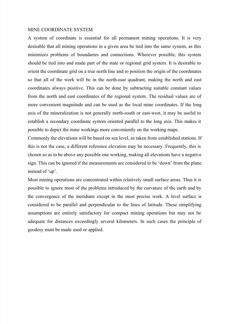
MINE COORDINATE SYSTEM
A system of coordinate is essential for all permanent mining operations. It is very
desirable that all mining operations in a given area be tied into the same system, as this
minimizes problems of boundaries and connections. Wherever possible, this systemshould be tied into and made part of the state or regional grid system. It is desirable to
orient the coordinate grid on a true north line and to position the origin of the coordinates
so that all of the work will be in the north-east quadrant, making the north and east
coordinates always positive. This can be done by subtracting suitable constant values
from the north and east coordinates of the regional system. The residual values are of
more convenient magnitude and can be used as the local mine coordinates. If the long
axis of the mineralization is not generally north-south or east-west, it may be useful to
establish a secondary coordinate system oriented parallel to the long axis. This makes it
possible to depict the mine workings more conveniently on the working maps.
Commonly the elevations will be based on sea level, as taken from established stations. If
this is not the case, a different reference elevation may be necessary. Frequently, this is
chosen so as to be above any possible one working, making all elevations have a negative
sign. This can be ignored if the measurements are considered to be µdown¶ from the plane
instead of µup¶.
Most mining operations are concentrated within relatively small surface areas. Thus it is
possible to ignore most of the problems introduced by the curvature of the earth and by
the convergence of the meridians except in the most precise work. A level surface is
considered to be parallel and perpendicular to the lines of latitude. These simplifying
assumptions are entirely satisfactory for compact mining operations but may not be
adequate for distances exceedingly several kilometers. In such cases the principle of
geodesy must be made used or applied.

8/3/2019 Mine Surveying Compile
http://slidepdf.com/reader/full/mine-surveying-compile 10/31
CONTOURS AND THEIR INTERPOLATION
A contour line (also isoclines or isarithm) of a function of two variables is a curve along
which the function has a constant value. In cartography, a contour line (often just called a
"contour") joins points of equal elevation (height) above a given level, such as mean sea
level. A contour map is a map illustrated with contour lines, for example a topographic
map, which thus shows valleys and hills, and the steepness of slopes. The contour
interval of a contour map is the difference in elevation between successive contour lines.
More generally, a contour line for a function of two variables is a curve connecting points
where the function has the same particular value. The gradient of the function is always
perpendicular to the contour lines. When the lines are close together the magnitude of the
gradient is large: the variation is steep. A level set is a generalization of a contour line for
functions of any number of variables.
Contour lines are curved or straight lines on a map describing the intersection of a real or
hypothetical surface with one or more horizontal planes. The configuration of these
contours allows map readers to infer relative gradient of a parameter and estimate that
parameter at specific places. Contour lines may be either traced on a visible three-
dimensional model of the surface, as when a photogrammetrist viewing a stereo-model plots elevation contours, or interpolated from estimated surface elevations, as when a
computer program threads contours through a network of observation points of area
centroids. In the latter case, the method of interpolation affects the reliability of
individual isoclines and their portrayal of slope, pits and peaks.
CARTOGRAPHY
Cartography is the study and practice of making maps. Combining science, aesthetics,
and technique, cartography builds on the premise that reality can be modeled in ways that
communicate spatial information effectively.
The fundamental problems of traditional cartography include:

8/3/2019 Mine Surveying Compile
http://slidepdf.com/reader/full/mine-surveying-compile 11/31
y Set the map's agenda and select traits of the object to be mapped. This is the concern
of map editing. Traits may be physical, such as roads or land masses, or may be
abstract, such as toponyms or political boundaries.
y Represent the terrain of the mapped object on flat media. This is the concern of map projections.
y Eliminate characteristics of the mapped object that are not relevant to the map's
purpose. This is the concern of generalization.
y Reduce the complexity of the characteristics that will be mapped. This is also the
concern of generalization.
y Orchestrate the elements of the map to best convey its message to its audience. This is
the concern of map design.
Modern cartography is closely integrated with geographic information science (GIS) and
constitutes many theoretical and practical foundations of geographic information systems.
Scales: objects are depicted in mine surveying plans by diminishing the results of natural
(field) measurements. The degree of diminution of a line in a plan is determined by the
scale, i.e. a dimensionless fractional number in which the numerator is unity and the
denominator shows how many times a line depicted in the plan can be laid off along the
corresponding horizontal distance in the terrain. This is what is called the numerical scale
of lengths, or simply numerical scale. Consequently, s/S = 1/M, where M is the
denominator of the numerical scale.
In plans, numerical scales are written as simple fractions for example, 1/500, 1/1000, etc.
thus, if a numerical scale 1/1000 has been adopted for a plan, this means that horizontal
distances on the terrain will be diminished on the plan to one thousandth. It is
distinguished between large and small scales. A plan drawn on a larger scale can depict
more details of a locality.
The scale of a plan or map is chosen according to specifications and depending on where
the plan will be used. Distances on plans can be measured with an accuracy permitted by
the resolving power of man¶s eye, which is usually taken equal to 0.1mm (with the

8/3/2019 Mine Surveying Compile
http://slidepdf.com/reader/full/mine-surveying-compile 12/31
critical angle of vision 60´ and the distance of best vision to an object 250mm, the
resolution is equal to 0.073mm or roughly 0.1mm).
PLANIMETER AND AREAS
A planimeter is a measuring instrument used to determine the area of an arbitrary two-
dimensional shape. They consist of a linkage with a pointer on one end, used to trace
around the boundary of the shape. The other end of the linkage is fixed for a polar
planimeter and restricted to a line for a linear planimeter. Tracing around the perimeter of
a surface induces a movement in another part of the instrument and a reading of this is
used to establish the area of the shape. The planimeter contains a measuring wheel that
rolls along the drawing as the operator traces the contour. When the planimeter's
measuring wheel moves perpendicular to its axis, it rolls, and this movement is recorded.
When the measuring wheel moves parallel to its axis, the wheel skids without rolling, so
this movement is ignored. That means the planimeter measures the distance that it¶s
measuring wheel travels, projected perpendicularly to the measuring wheel's axis of
rotation. The area of the shape is proportional to the number of turns through which the
measuring wheel rotates when the planimeter is traced along the complete perimeter of the shape. Developments of the planimeter can establish the position of the first moment
of area (center of mass), and even the second moment of area.
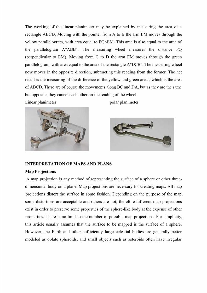
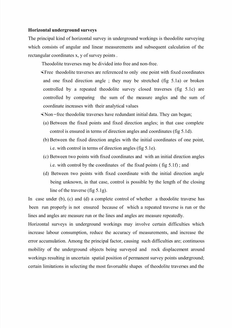
The pictures show a linear and a polar planimeter. The pointer M at one end of the
planimeter follows the contour C of the surface S to be measured. For the linear
planimeter the movement of the "elbow" E is restricted to the y-axis. For the polar
planimeter the "elbow" is connected to an arm with fixed other endpoint O. Connected to
the arm ME is the measuring wheel with its axis of rotation parallel to ME. A movement
of the arm ME can be decomposed into a movement perpendicular to ME, causing the
wheel to rotate, and a movement parallel to ME, causing the wheel to skid, with no
contribution to its reading.
8/3/2019 Mine Surveying Compile
http://slidepdf.com/reader/full/mine-surveying-compile 13/31
The working of the linear planimeter may be explained by measuring the area of a
rectangle ABCD. Moving with the pointer from A to B the arm EM moves through the
yellow parallelogram, with area equal to PQ×EM. This area is also equal to the area of
the parallelogram A"ABB". The measuring wheel measures the distance PQ(perpendicular to EM). Moving from C to D the arm EM moves through the green
parallelogram, with area equal to the area of the rectangle A"DCB". The measuring wheel
now moves in the opposite direction, subtracting this reading from the former. The net
result is the measuring of the difference of the yellow and green areas, which is the area
of ABCD. There are of course the movements along BC and DA, but as they are the same
but opposite, they cancel each other on the reading of the wheel.
Linear planimeter polar planimeter
INTERPRETATION OF MAPS AND PLANS
Map Projections
A map projection is any method of representing the surface of a sphere or other three-
dimensional body on a plane. Map projections are necessary for creating maps. All map
projections distort the surface in some fashion. Depending on the purpose of the map,
some distortions are acceptable and others are not; therefore different map projections
exist in order to preserve some properties of the sphere-like body at the expense of other
properties. There is no limit to the number of possible map projections. For simplicity,
this article usually assumes that the surface to be mapped is the surface of a sphere.
However, the Earth and other sufficiently large celestial bodies are generally better
modeled as oblate spheroids, and small objects such as asteroids often have irregular

8/3/2019 Mine Surveying Compile
http://slidepdf.com/reader/full/mine-surveying-compile 14/31
shapes. These other surfaces can be mapped as well. Therefore, more generally, a map
projection is any method of "flattening" into a plane a continuous surface having
curvature in all three spatial dimensions.
Projection as used here is not limited to perspective projections, such as those resulting
from casting a shadow on a screen, or the rectilinear image produced by a pinhole camera
on a flat film plate. Rather, any mathematical function transforming coordinates from the
curved surface to the plane is a projection.
Carl Friedrich Gauss's Theorema Egregium proved that a sphere cannot be represented on
a plane without distortion. Since any method of representing a sphere's surface on a plane
is a map projection, all map projections distort. Every distinct map projection distorts in a
distinct way. The study of map projections is the characterization of these distortions.
A map of the Earth is a representation of a curved surface on a plane. Therefore a map
projection must have been used to create the map, and, conversely, maps could not exist
without map projections. Maps can be more useful than globes in many situations: they
are more compact and easier to store; they readily accommodate an enormous range of
scales; they are viewed easily on computer displays; they can facilitate measuring
properties of the terrain being mapped; they can show larger portions of the Earth'ssurface at once; and they are cheaper to produce and transport. These useful traits of
maps motivate the development of map projections.
Many properties can be measured on the Earth's surface independently of its geography.
Some of these properties are: Area, Shape, Direction, Bearing, Distance and Scale.
Map projections can be constructed to preserve one or more of these properties, though
not all of them simultaneously. Each projection preserves or compromises or
approximates basic metric properties in different ways. The purpose of the map
determines which projection should form the base for the map. Because many purposes
exist for maps, many projections have been created to suit those purposes.
Another major concern that drives the choice of a projection is the compatibility of data
sets. Data sets are geographic information. As such, their collection depends on the

8/3/2019 Mine Surveying Compile
http://slidepdf.com/reader/full/mine-surveying-compile 15/31
chosen model of the Earth. Different models assign slightly different coordinates to the
same location, so it is important that the model be known and that the chosen projection
be compatible with that model. On small areas (large scale) data compatibility issues are
more important since metric distortions are minimal at this level. In very large areas(small scale), on the other hand, distortion is a more important factor to consider.
Construction of a map projection
The creation of a map projection involves two steps:
i. Selection of a model for the shape of the Earth or planetary body (usually choosing
between a sphere or ellipsoid). Because the Earth's actual shape is irregular,
information is lost in this step.
ii. Transformation of geographic coordinates (longitude and latitude) to Cartesian (x,y)
or polar plane coordinates. Cartesian coordinates normally have a simple relation to
eastings and northings defined on a grid superimposed on the projection.
Some of the simplest map projections are literally projections, as obtained by
placing a light source at some definite point relative to the globe and projecting its
features onto a specified surface. This is not the case for most projections which are
defined only in terms of mathematical formulae that have no direct physicalinterpretation.
ROLE OF MINE SURVEYING SERVICE IN MINING SAFETY
Modern mining can be characterized by ever increasing depths of mines and accordingly,
more complicated geological and hydrological conditions. With an increase in the mining
depth, rock pressure increases intensively. moreover the cases of sudden rock, coal, gas
and water outbursts, self ignition of coal, etc. are more probable to occur in deeply
bedded seams. Under such conditions, special methods and means are required for
carrying out the stoping and preparatory mining operations, which should be strictly
observed and controlled properly to ensure the safety and efficiency of mining.

8/3/2019 Mine Surveying Compile
http://slidepdf.com/reader/full/mine-surveying-compile 16/31
Under the conditions of elevated hazard of mining, mine surveying service plays an
important part and has certain specifics. In many aspects of mining safety, mine
surveying service takes the prime role and is responsible for making decisions which are
obligatory for all other mining specialists and workers. To ensure safety control, minesurveyors determine the boundaries of harzardous zones and represent them on the plans
of the mining workings are approaching harzardous zones, participate in the development
of safety measures, and observe that these measures fulfilled properly. There are three
principal groups of hazardous zones which may be associated with:
a) Flooded mining workings;
b) Formation of zones of elevated rock pressure between adjacent seams, and
c) Formation of unprotected zones and zones of elevated rock pressure in seams liable to
outbursts.
Hazardous zones associated with flooded workings can in turn be divided into the
following types:
a) Zones near flooded or gassy workings in a single seam
b) Those near flooded or gassy workings in adjacent seams;
c) Zones near flooded workings driven in the overburden;
d) Those near unplugged or poorly plugged boreholes; and
e) Zones near tectonic disturbances (dislocations)
In mine surveying practice, dangerous conditions are encountered most often in workings
approaching flooded or gassy old workings. Methods for the construction of safe
boundaries and special safety measures of the mining work have been developed for each
type of hazardous zone.

8/3/2019 Mine Surveying Compile
http://slidepdf.com/reader/full/mine-surveying-compile 17/31
HORIZONTAL SURVEYS OF UNDERGROUND WORKINGS
The principal sources of mine surveying are;
1. Underground workings (opening, preparatory, development, stopping ,
draining, exploratory , etc).2. Boreholes (prospecting, operating, unwavering, water observation, etc).
3. Boundaries of safe mining work, safety and barrier pillars.
4. Contours of inundated, gas laden, and caved workings, centre of
underground fires, isolating partition and other ventilation structure, gas
blower sites, areas and contours dangerous in gas or rock outbursts, rock
bump, water inrush, floating earth, source of underground water, etc;
5. Characteristics points of bedding elements of mineral deposits
6. Point for documentation of geological disturbances and other textural and
structural characteristics of deposits and enclosing rocks;
7. Point of mineral assaying
8. Location of surface and underground artificial structures and stationary
equipment in underground workings.(hoists, explosive store, informative
sheds)
The errors permissible in the measurements of horizontal and indignation angles and
side lengths in polygon metric traverses can be characterized by the data given below.
RMs error of
measured
horizontal
angle $M
RMs error of
measured
indication
angle ; MV
Coefficient of
influence in
linear
measurements
Length
independent
component ,
V
Random Systematic P
20´ 30´ 0.001 0.00005 0.01
8/3/2019 Mine Surveying Compile
http://slidepdf.com/reader/full/mine-surveying-compile 18/31
Horizontal underground surveys
The principal kind of horizontal survey in underground workings is theodolite surveying
which consists of angular and linear measurements and subsequent calculation of the
rectangular coordinates x, y of survey points .Theodolite traverses may be divided into free and non-free.
Free theodolite traverses are referenced to only one point with fixed coordinates
and one fixed direction angle ; they may be stretched (fig 5.1a) or broken
controlled by a repeated theodolite survey closed traverses (fig 5.1c) are
controlled by comparing the sum of the measure angles and the sum of
coordinate increases with their analytical values
Non free theodolite traverses have redundant initial data. They can begun;
(a) Between the fixed points and fixed direction angles; in that case complete
control is ensured in terms of direction angles and coordinates (fig 5.1d).
(b) Between the fixed direction angles with the initial coordinates of one point,
i.e. with control in terms of direction angles (fig 5.1e).
(c) Between two points with fixed coordinates and with an initial direction angles
i.e. with control by the coordinates of the fixed points ( fig 5.1f) ; and
(d) Between two points with fixed coordinate with the initial direction angle
being unknown, in that case, control is possible by the length of the closing
line of the traverse (fig 5.1g).
In case under (b), (c) and (d) a complete control of whether a theodolite traverse has
been run properly is not ensured because of which a repeated traverse is run or the
lines and angles are measure run or the lines and angles are measure repeatedly.
Horizontal surveys in underground workings may involve certain difficulties which
increase labour consumption, reduce the accuracy of measurements, and increase the
error accumulation. Among the principal factor, causing such difficulties are; continuous
mobility of the underground objects being surveyed and rock displacement around
workings resulting in uncertain spatial position of permanent survey points underground;
certain limitations in selecting the most favoruable shapes of theodolite traverses and the
8/3/2019 Mine Surveying Compile
http://slidepdf.com/reader/full/mine-surveying-compile 19/31
best lengths of traverse sides; constricted conditions for surveying in underground
working; poor illumination of working places; dust laden atmosphere in mines.
In order to minimize the influence of the factors indicated on the accuracy of surveys and
to avoid unproductive labour expenditure, it is essential to adhere to the following main principles in surveying work,
1. Mine surveying should proceed from the more general and more precise procedure to
more particular and less accurate work.
2. In any kind of surveying work, all measurement must be done with the optimum
accuracy sufficient for the purpose.
3. Mine surveying must be carried out under an appropriate and timely control both of
the field and in the office analysis of the results of survey.
For reliable and efficient performance of mine surveying, it is essential before starting
the work, to study can fully the conditions of the field work to draft the plan of
construction of survey traverses by the results of reconnaissance and consider in it the
existing peculiarities, narrow` place, etc; to determine the set of surveying instruments
and equipments, to test and adjust the instrument, to assign performers for the survey
work plan, and, when required, to make preliminary calculation of the accuracy of
surveys.
VERTICAL SURVEYS IN UNDERGROUND WORKINGS
Vertical survey, or leveling is a survey procedure in which the height difference of
some points over other are measure in a certain sequence, and then the required height
of point are calculated from the height of initial points and the height difference
measured.
This can be made by two methods which include:
(i) Geometric or direct leveling
(ii) Trigonometric or indirect leveling
The former method is employed in underground workings with small inclination angles
(up to 50) and the latter in steeper working.
8/3/2019 Mine Surveying Compile
http://slidepdf.com/reader/full/mine-surveying-compile 20/31
The height transfer by geometric leveling should satisfy the following requirements.
a. The discrepancies of measured heights of points should not exceed 50mm in
polygonometric traverses or 80mm in theodolite traverses ( where L is the length of a
traverse line. Km)
b. Staff spacing should not exceed 200m in length and differ from one another by more
than 10m.
c. leveling lines between the initial bench marks should be close or run forward and
back.
d. the discrepancies of height difference at a station, as read off on the black and red
face of staff or at two different settings of the level instrument, should not exceed
10mm, and.
e. before starting the leveling procedure the available station points should be checked
for stability.
The discrepancies between the height difference established earlier and the test one
should not exceed 10 and 20mm respectively in polygon metric and theodolite traverses.
When transferring the height marks in underground working by trigonometric leveling,
the following accuracy requirements should be observed.
a. The permissible discrepancy of a zero offset in the measurements of indignation
angles is 1.51 in polygonmetric traverses;
b. The discrepancy of height difference determined for a line by leveling form and
back should be not more than 1/2000 of the side length in polygonometric traverses
or 1/1000 in theodolite traverses;
c. The discrepancy of two measured heights of theodolite and signals should be not
more than 5mm in polygonometric traverses or 10mm in theodolite traverses; and
d. The discrepancy in the height differences of the entire line of levels in polygon metric
traversing should be in polygonometric traversing should be not more than;
1/n + sin2S/3

8/3/2019 Mine Surveying Compile
http://slidepdf.com/reader/full/mine-surveying-compile 21/31
Where (s) is the total inclined length of the forward and back traverese; m; n is the
total number of sides in the forward and back traverses.
S= mean indignation angle of traverse sides.
In theodolite traversing this discrepancy should be not more than 120mm
PRACTICALS
Distance measurements
The standard device for measuring distance in surface or underground tranverses is the
steel tape. In mine surveying, the distances commonly are measured along the line of
sight from the horizontal axis of the telescope to the sighting point. This is known as
slope chaining. The technique is preferred to horizontal chaining because of the frequent
steeply inclined lines of sight and because of its higher accuracy. The tapes used are of
20, 30, and 50m. The best steel tape is the 50m; because it increases the rate of
measurement and accuracy. Ordinarily transversing work seldom requires correction for
temperature or precise control of the pull. These factors must be taken into consideration
for very precise work such as in determing the exact length of a base line for
triangulation.
Leveling Transversing (with tapes and total stations)
Vertical surveys or leveling is a survey procedure in which the height differences
(elevations) of some points over others are measured in a certain sequence and then the
required heights of points are calculated from the heights of initial points and the height
differences measured. As regards to surface mining, leveling is the operation required in
the determination or more strictly, the comparison of height of points on the surface of

8/3/2019 Mine Surveying Compile
http://slidepdf.com/reader/full/mine-surveying-compile 22/31
the earth. In underground mining, vertical surveys are carried out in order to determine
the height marks of individual points established in underground workings, to assign the
specified slope (grade) to workings, to plot longitudinal and vertical profiles and sections,
to determine the height of marks of the characteristic points of deposits (seams); thesemeasurements are essential for the solution of mining geometry and mine geometrization
problems.
If a whole series of heights is given relative to a plane, this plane is called a datum; and in
topographical work; the datum used is the mean level of the sea, since it makes
international comparism of heights possible. This level is termed ordinance datum and is
the one which will normally be used, though on small works, an ordinary datum may be
chosen.
The basic equipment required in leveling is:
a) A device which gives a truly horizontal line (the level),
b) A suitable graduated staff for reading vertical heights (the leveling staff),
c) In addition, equipment is necessary to enable the points leveled to be located
relative to each other on a map plan or section, this might be for example chain
tape, tacheometer or plane table etc.
Procedure in leveling:
The basic operation is the determination of the difference in level between two points.
Consider two points A and B as shown below:

8/3/2019 Mine Surveying Compile
http://slidepdf.com/reader/full/mine-surveying-compile 23/31
If the readings on A and B are 3.222m and 1.414m respectively, then the diffence in level
between A and B is equal to AC i.e 3.222-1.414=1.808m and this represent a rise in the
height of the land at B relative to A. if the readings at B is greater than at A, say 3.484m,
then the difference in level would be 3.484-3.222=0.262m, and this would represent a fallin the height of the land at B relative to A. thus we have that in any two successive staff
readings:
If 2nd reading is less than 1st, then it represents a rise, If 2nd reading is greater than the 1st ,
, then it represent a fall.
If the actual level of one of the two points is known, the level of the other may be found
by either adding the rise or subtracting the fall. The levels at A and B are known as
reduced levels (R.L) as they give the level of the land at these points reduced or referred
to a datum level (in case ordinance datum, which the mean height of Newline) and this
method of reducing the staff reading gives a system of booking known as the Rise and
Fall method.
A second method is known as the height of collimation method, also exists and since the
two methods are in common use they must both be known. In the second method, the
height of the line of collimation above the datum is found by adding the staff reading
obtained with the staff on a point of known level to the R.L of that point.
Thus, in 3.22 the height of collimation is 128.480+3.222=137.702m AOD and this will
remain constant until the level is moved to another position. The levels of points such as
B are determined by deducting the staff reading at these points from the height of
collimation.
a) Level at B= height of coll. Reading at B
= 131.702-1.414=130.288m AOD
b) Level at B = height of collimation Reading at B
= 131.702 3.484
= 128.218m AOD

8/3/2019 Mine Surveying Compile
http://slidepdf.com/reader/full/mine-surveying-compile 24/31
General Procedure:
This could be dealt with by means of an example and we will consider the line of levels
down the centre line of the road as shown in the plan below:
The instrument is set up at a convenient position p such that a bench mark (B.M) may be
observed. Bench marks are points of known elevation above ordinance datum which have
been established by surveyors of the of the ordinance survey. The commonest types are in
the form of a broad arrow on permanent features such as bridge, parapets etc.
The 1st reading made with the staff on a point of known reduced level (which need not, of
course be a bench mark) is known as a backsight (B.S), and this term will now be used to
denote that reading taken immeadiately after setting up the instrument with the staff on a
point of known level. The staff is now held at a point A, B and C in turn and readings
which are known as intermediate sights are taken. It is found that no readings after D are possible due to either change is in level of the ground surface or some obstruction to the
line of sight and it Is therefore necessary change the position off the instrument. The last
reading on D is then known as foresight (F.S) and is final taken before moving the
instrument. The point D is itself is known as change point because it is the staff position
of the level is being changed.
The instrument is moved to Q setup and leveled and the reading a backsight, taken on the
staff at the change point D followed by intermediate sights (I.S) with the staff on points atwhich levels are required until a further change becomes necessary resulting in a
foresight on point G. this procedure is repeated
until the requires levels have been obtained.

8/3/2019 Mine Surveying Compile
http://slidepdf.com/reader/full/mine-surveying-compile 25/31
BOOKING: Rise and Fall method
The readings are booked in a level book which is specially printed for the purpose as
shown below.
The booking of the Rise and fall systemB.S I.S F.S Rise Fall R.L Distance Remark
o.663 98.760 B.M=98.760
1.946 1.283 97.477 0 STAFF
STATION
A
1.008 0.938 98.415 20 B
1.153 0.145 98.270 40 C
2.788 1.585 0.432 97.838 60 D
CHANGE
POINT
2.270 0.517 98.355 80 E
1.218 1.052 99.407 100 F
0.646 0.572 99.979 120 G
3.350 2.231 3.079 1.860 Last R.D
2.231 =99.979
(- R.D of O.D)
-98.78
1.219
As a check on the arithmetic involved in reducing the levels, the backsightd and
foresights and the rises and falls must be summed up.
The checks are then:
(Backsights) - (Foresights) = (Rises) - (Falls) = Last R.L First R.L.
It must be pointed out that these checks concern only the accuracy of the reductions and
have no effect on the accuracy of the recordings themselves.

8/3/2019 Mine Surveying Compile
http://slidepdf.com/reader/full/mine-surveying-compile 26/31
Height of collimation method
B.S Intersight Foresight Height of
collimation
Reduced
level
Distance Remarks
0.663 99.423 98.760 B.M 98.76
O.D
1.946 97.477 0 STAFF AT
A
1.008 98.415 20 B
1.153 98.270 40 C
2.787 1.585 100.625 97.838 60 D
CHANGE
OF POINT
2.270 98.355 80 E
1.218 99.407 100 F
0.646 99.979 120 G
3.450 2.311 99.979
-2.231 - 98.760
1.219 1.219
The height of collimation is obtained by adding the staff reading which must be a
backsight to the known R.L of the point on which the staff stands. All other readings are
deducted from the height of collimation until the instrument setting is changed,
whereupon the new height of collimation is determined by adding the backsight to the
R.L at the change point.
The arithmetrical checks to be applied to this system of booking are:
(B.S) - (F.S) = Last R.L First R.L
8/3/2019 Mine Surveying Compile
http://slidepdf.com/reader/full/mine-surveying-compile 27/31
(all R.L¶s except the first) = (each instrument height) × (number of intersights and
F.S¶s deduced from it) - (F.S + I.S)
Reduction is easier with the height of collimation method when leveling for earthworks
and karge numbers of intermediate sights are taken from each position of the instrument.
The Gyro-Theodolite
A gyro-theodolite is a surveying instrument composed of a gyroscope mounted to a
theodolite. It is used to determine the orientation of true north by locating the meridian
direction. It is the main instrument for orientating in mine surveying and in tunnel
engineering, where astronomical star sights are not visible.
The gyro-theodolite in its present form is a recently developed instrument which
revolutionizes the task of carrying azimuth into underground mines. It is lightweight, self
contained apparatus giving results of great accuracy in a short time. It does not require
the use of a shaft, nor does it interfere with normal mine operations if there is an unused
heading of sufficient length to a back sight line. It is operated by one instrument man and
a recorder. Similar units are supplied by several manufacturers.
The basic unit consists of a very precise gyroscope suspended by a short thin metallic band. The gyro is housed in a metal case which mounts on top of a theodolite. A
gyroscope is mounted in a sphere, lined with Mu-metal to reduce magnetic influence,
connected by a spindle to the vertical axis of the theodolite. The battery-powered gyro
wheel is rotated at 20,000 rpm or more, until it acts as a north-seeking gyroscope. A
separate optical system within the attachment permits the operator to rotate the theodolite
and thereby bring a zero mark on the attachment into coincidence with the gyroscope spin
axis. Power is supplied by a portable battery which activates a converter supplying
alternate current to the gyro meter. The position of the gyro is observed through an
illuminated eyepiece. The gyro is clamped in position while being moved and brought up
to speed. When the rapidly revolving gyro is uncase its axis horizontal and pointed
toward some particular spot on the tripod stands, however, is revolving. This with gravity

8/3/2019 Mine Surveying Compile
http://slidepdf.com/reader/full/mine-surveying-compile 28/31
produces a force on the gyro, to which it reads by swinging its north end toward north.
The momentum of the gyro causes it to over swing and thus to oscillate about the
astronomical north line. The techniques of observation vary somewhat among the
different types of instrument, but the basic approach is to find the mean position of theswing from a series of observations.
The physics of the gyro do not permit the theodolite to be used in the erect and inverted
positions. Consequently, these must be determined by setting up the instrument on a line
of known azimuth, obtaining the angle from that liune that line to astronomical north as
indicated by the gyro and using the difference as the correction factor.
This work is commonly done on the surface before taking the equipment underground.
Having determined the correction constant to be uused, the surveyor takes the equipment
underground to the place where the azimuth is to be determined. Setting up under one
permanent point to the backsights another, preferably several 30m away. He then brings
the gyro up to the speed, uncages it and proceeds to find the exact angle between his line
and true north. Applying his correction he now has the true azimuth of fixed line. He will
normally repeat the operation from other end as a check. When not in operation, the
gyroscope assembly is anchored within the instrument. The electrically powered
gyroscope is started while restrained and then released for operation. During operation
the gyroscope is supported within the instrument assembly, typically on a thin vertical
tape that constrains the gyroscope spinner axis to remain horizontal. The alignment of the
spin axis is permitted to rotate in azimuth by only the small amount required during
operation. An initial approximate estimate of the meridian is needed. This might be
determined with a magnetic compass, from an existing survey network or by the use of
the gyro-theodolite in an extended tracking mode.

8/3/2019 Mine Surveying Compile
http://slidepdf.com/reader/full/mine-surveying-compile 29/31
A gyroscope mounted on a theodolite
Although a gyro-theodolite functions at the equator and in both the northern and southern
hemispheres, it cannot be used at either the North Pole or South Pole, where the Earth's
axis is precisely perpendicular to the horizontal axis of the spinner and the meridian is
undefined. Gyro-theodolites are not normally used within about 15 degrees of the pole
because the east-west component of the Earth¶s rotation is insufficient to obtain reliable
results. Unlike an artificial horizon or inertial navigation system, a gyro-theodolite cannot
be relocated while it is operating. It must be restarted again at each site.
The GPS instruments
The Global Positioning System (GPS) is a space-based global navigation satellite system
(GNSS) that provides location and time information in all weather, anywhere on or near
the Earth, where there is an unobstructed line of sight to four or more GPS satellites. It is
maintained by the United States government and is freely accessible by anyone with a
GPS receiver with some technical limitations which are only removed for military users.
With the advent of the Global Positioning System (GPS), elevation can also be derived
with sophisticated satellite receivers, but usually with somewhat less accuracy than with
traditional precise leveling. However, the accuracies may be similar if the traditional
8/3/2019 Mine Surveying Compile
http://slidepdf.com/reader/full/mine-surveying-compile 30/31
leveling would have to be run over a long distance. Surveyors use absolute locations
gotten through GPS instruments to make maps and determine property boundaries.
GPS, or Global Positioning Systems, are used extensively by surveyors as they provide
accurate latitude and longitude positions. GPS systems use radio signals from navigationsatellites to determine the position. Two types of GPS instruments exist; all-in-one
receivers, which have the GPS receiver, antenna and data collector built into the same
device, and standalone receivers consisting only of the GPS receiver and antenna.
Standalone receivers need to be connected to computers to access the data.
Trimble GeoXH: The Trimble GeoXH is a handheld all-in-one GPS Geographic
Information System. device. This GPS instrument is often used for electric and gas
utilities, land reform projects, water and wastewater services where on-the-spot
positioning is very important. The GeoXH features an internal antenna, but an external
antenna can be attached to the device to achieve decimeter accuracy. With 128 MB
RAM, 1GB storage space and a 530 MHz processor, the device supports working with
maps and large data sets in the field. Industry standard Windows Mobile 6 operating
system powers this handheld device. Bluetooth and LAN network connection is possible
with the GeoXH to transfer data to and from other devices.
MobileMapper CX: The MobileMapper CX is another all-in-one handheld GPS receiver
for universal Geographic Information System collection. This device provides real-time
sub-meter and sub-foot accuracy and supports Bluetooth wireless technologies as well as
DGPS networking. The device supports SD storage cards, which are used in digital
cameras today, and works with a replaceable battery. Surveyors use the MobileMapper
CX to create or update maps for analysis and storage.

8/3/2019 Mine Surveying Compile
http://slidepdf.com/reader/full/mine-surveying-compile 31/31
GMS-2 Pro: This handheld dual constellation tracking GPS receiver consists of an
integrated laser distance meter, digital camera, bar code reader and digital compass.
Surveyors can take digital photographs of structures and upload them directly to their
Geographic Information System. Each photograph can be geo-tagged with the GPScoordinates. An internal laser distance meter, compass and tilt sensor work together to
map offset points. The GMS-2 Pro supports Bluetooth and other network connections, as
well as USB data transfer.
GPS Pathfinder ProXH: The GPS Pathfinder ProXH features a GPS receiver, antenna and
battery. It is a standalone device, which connects to a field computer via a Bluetooth
wireless connection. The GPS Pathfinder ProXH can be connected to computers, laptops,
tablet PCs and PDAs. The device delivers sub-foot accuracy, which can be enhanced by
connecting an extra antenna to it.