miga: combining laser and matter wave … · miga: combining laser and matter wave interferometry...
TRANSCRIPT

MIGA: Combining laser and matter wave interferometry formass distribution monitoring and advanced geodesy
B. Canuela,b, S. Pelissona,b, L. Amanda,c, A. Bertoldia,b, E. Cormiera,d, B. Fanga,c, S. Gaffeta,e,R. Geigera,c, J. Harmsf,g, D. Hollevillea,c, A. Landragina,c, G. Lefevrea,b, J. Lhermitea,d, N.
Mieleca,c, M. Prevedellih, I. Rioua,b, and P. Bouyera,b
aMIGA ConsortiumbLP2N, Laboratoire Photonique, Numerique et Nanosciences, Universite
Bordeaux–IOGS–CNRS:UMR 5298, rue F. Mitterrand, F–33400 Talence, France.cLNE–SYRTE, Observatoire de Paris, PSL Research University, CNRS, Sorbonne Universites,
UPMC Univ. Paris 06, 61 avenue de l’Observatoire, F–75014 Paris, FrancedCELIA, Centre Lasers Intenses et Applications, Universite Bordeaux-CNRS-CEA-UMR 5107,
F–33405 Talence, FranceeGEOAZUR, UNSA, CNRS, IRD, OCA , 250 rue Albert Einstein, 06560 Valbonne, France
fINFN, Sezione di Firenze, I-50019 Sesto Fiorentino, ItalygUniversita degli studi di Urbino ‘Carlo Bo’, I-61029 Urbino, Italy
hDipartimento di Fisica e Astronomia, Universita di Bologna, Via Berti-Pichat 6/2, I–40126Bologna, Italy
ABSTRACT
The Matter-Wave laser Interferometer Gravitation Antenna, MIGA, will be a hybrid instrument composed of anetwork of atom interferometers horizontally aligned and interrogated by the resonant field of an optical cavity.This detector will provide measurements of sub Hertz variations of the gravitational strain tensor. MIGA willbring new methods for geophysics for the characterization of spatial and temporal variations of the local gravityfield and will also be a demonstrator for future low frequency Gravitational Wave (GW) detections. MIGA willenable a better understanding of the coupling at low frequency between these different signals. The detector willbe installed underground in Rustrel (FR), at the “Laboratoire Souterrain Bas Bruit” (LSBB), a facility withexceptionally low environmental noise and located far away from major sources of anthropogenic disturbances.We give in this paper an overview of the operating mode and status of the instrument before detailing simulationsof the gravitational background noise at the MIGA installation site.
Keywords: Atom interferometry, Newtonian Noise, Gravitational Waves, Underground facilities
1. INTRODUCTION
After the development in the 1980’s of cooling and trapping techniques for neutral atoms,1 it became possibleto demonstrate the wave behavior of massive particles at the atomic level,2 using micro-fabricated gratings3,4 oroptical lattices5,6 to coherently manipulate the atomic wave function. Since then, the field of atom interferometryhas known an incessant development,7 and nowadays sensors based on matter wave interference phenomena areused to probe inertial forces (like acceleration,8 gravity gradient,9 rotation10,11), measure fundamental constants(like the gravitational constant G,12,13 and h/M14), and are investigated as possible means to test a long list ofdisparate effects and theories (like the weak equivalence principle in general relativity,15–21 matter neutrality,22
and dark energy23,24).
A few years ago large scale atom gradiometers have been proposed to monitor the strain tensor in the infra-sound bandwidth,25 with the aim of detecting GWs. Different configurations have been considered to install
Further author information:Send correspondence to [email protected]
arX
iv:1
604.
0207
2v1
[ph
ysic
s.at
om-p
h] 7
Apr
201
6

very long baseline atom interferometers in space26–30 and on ground.31 We are building a large scale atominterferometer array in an underground laboratory with the two-fold aim to measure tiny variations of gravityinduced by geophysical phenomena and to implement a demonstrator for sub-Hz GW detection, with an initialstrain sensitivity of the order of 10−13. Future evolutions of this instrument could enable to observe on Earth GWsources in a frequency band forbidden to optical detectors. This prospect assumes a new relevance in relationto the recent first detection of GWs,32 which shifts the interest to GW astronomy and hence to the widening ofthe observation bandwidth through different classes of detectors.33
2. MEASURING STRAIN VARIATIONS WITH AN IN-CAVITY ARRAY OF ATOMINTERFEROMETERS
The MIGA antenna34,35 will consist of three 87Rb Atom Interferometers (AIs) horizontally aligned and inter-rogated by the resonant field of a 300 m long cavity. By using a three pulse π/2, π, π/2 sequence,6 each AIbecomes sensitive to both horizontal accelerations and to variations of the phase of the interrogation field duringthe interrogation sequence. In a gradiometer configuration, couples of in-cavity interferometers will thereforeprovide access to the horizontal gravity gradient and more generically to the differential phase variation betweenthe distant atom sources. Such differential phase fluctuations may arise from strain variations of the space-timemetric induced by GWs.36
2.1 MIGA Atom Interferometers
The different AIs of the antenna are simultaneously created using a set of three in-cavity π/2, π, π/2 light pulses.The matter-waves are manipulated using Bragg diffraction37 of the atoms on the cavity standing wave. Suchprocess couples atomic states of momentum |+~k〉 and |−~k〉 where k is the wave vector of the interrogation field.The interferometer geometry is described in Fig. 1. The atoms, initially in the |+~k〉 state, first experience a π/2
⏐+ħk〉
⏐+ħk〉 ⏐-‐ħk〉
π
π/2
P = 12(1− cosΔΦAT )
30 cm
Figure 1: Geometry of the MIGA atom interferometers. Atoms are launched on the vertical trajectory and experiencea set of cavity enhanced π/2, π, π/2 pulses that creates a matter-wave interferometer on the external states|+~k〉 and |−~k〉. The π pulse is realized at the apex of the atom trajectories.
pulse creating an equiprobable coherent superposition between the |+~k〉 and |−~k〉 states. The matter-wavesare then deflected by the use of a π pulse reversing the atomic states, before being recombined with a secondπ/2 pulse. At the interferometer output the transition probability P between the states is given by:
P =1
2(1− cos ∆φAT ). (1)

2.2 Strain measurement with the Atom Interferometers of the antenna
The atom phase shift ∆φAT (Xi) of the AI located at Xi along the cavity will measure the horizontal accelerationssa(Xi) together with strain variations induced by GWs. We consider in the following that fluctuations ofcavity mirror position x1(t) and x2(t) and laser frequency noise δν(t) are the only sources of experimentalnoise∗. Considering variations of these effects with characteristic frequencies smaller than the linewidth of theinterrogation cavity, the atom phase shift for an AI placed in the cavity is similar to that of a simple retro-reflection configuration:39
∆φAT (Xi) =4πν0c
sx2 +4π
c
[−sδν +
ν02sh
](Xi − L) + sa(Xi) + ε(Xi), (2)
where ν0 is the laser frequency, h the GW strain variation, L the cavity length and ε(Xi) is the detectionnoise (atom shot noise). The term sa(Xi) accounts for the weighting of the time-dependent fluctuations of
local accelerations by the sensitivity function of the AI to accelerations: sa(Xi) =∫∞−∞ sa(t)da(Xi,t)
dt dt. Other
time-fluctuating effects are weighted by the regular phase sensitivity function of the AI40 (sx2 ,sδν and sh). Thedifferential signal between two in-cavity AIs placed at Xi and Xj is therefore:
∆φAT (Xi)−∆φAT (Xj) =4π
c
[−sδν +
ν02sh
](Xi −Xj) + sa(Xi)− sa(Xj) + ε(Xi)− ε(Xj). (3)
This signal thus presents strong immunity to vibration of the cavity end mirror. Vibrations of other opticalelements may also re-couple to differential measurement though generation of frequency noise41 δν(t), but thiscontribution will remain negligible with respect to detection noise in the initial instrument configuration.
This gradiometer configuration couples gravity gradient signals with strain variations induced by GW overa certain baseline. The use of an array of correlated AIs offers simultaneous measurements of both effectsover different characteristic lengths. Such configuration may enable to reduce the influence of gravity gradientfluctuations on the GW measurements by taking advantage of the correlation properties of the local gravityacceleration noise,39 and opens the possibility to detect gravitational radiation at low frequency on Earth. Theuse of a dense network of AIs may also permit to measure the space-time variations of the local gravity field,with important outputs in geophysics for mass transport monitoring, hydrogeology and underground survey.
In Sec. 4, we detail the first projection of background gravity gradient noise (called in the following NewtonianNoise, NN) on the differential signals of the MIGA AIs. Remarkably, the precise modelization of such noise isat the heart of NN rejection methods for GW detection.39
3. THE MIGA ANTENNA
In this section, we give an overview of the antenna operating principle, focusing on the AIs and the interrogationcavity. We also describe the infrastructure work required at “Laboratoire Souterrain Bas Bruit” (LSBB) to hostthe MIGA instrument.
3.1 Instrument
3.1.1 Atom Interferometers
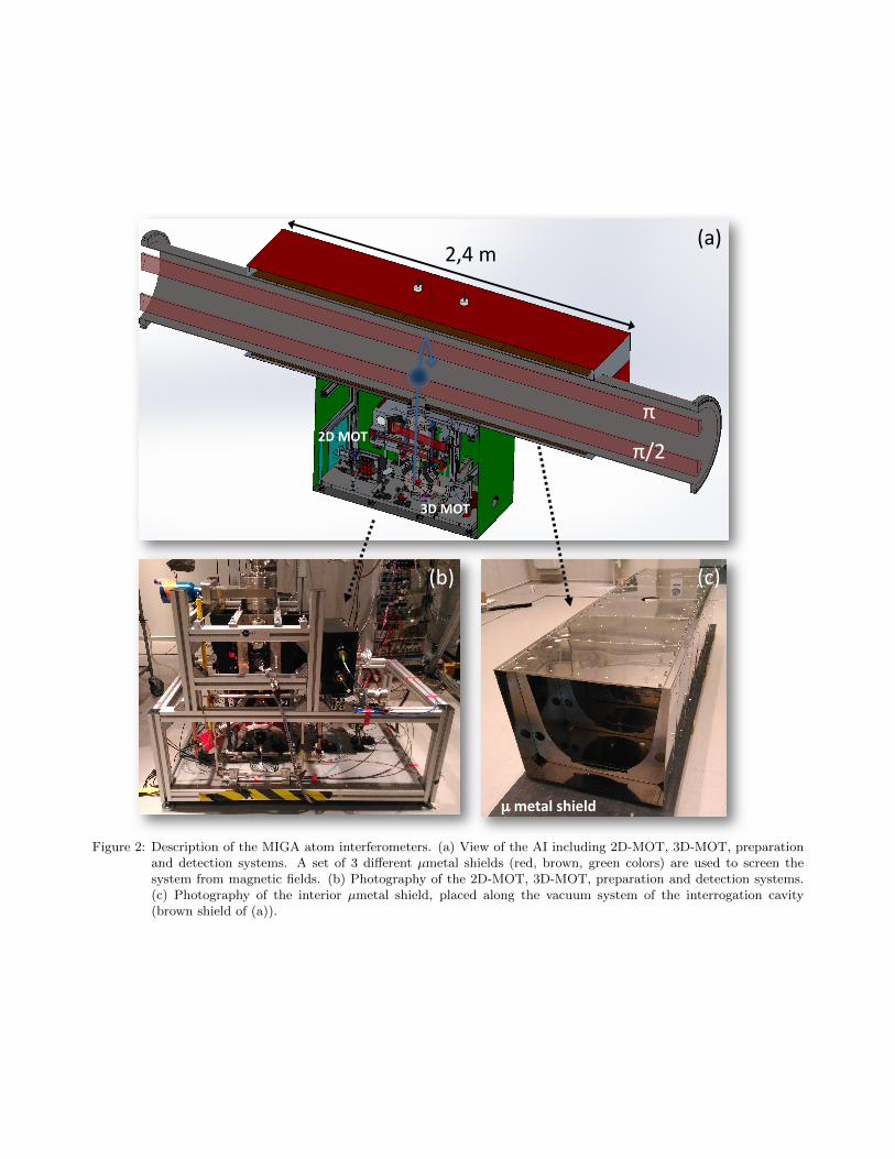
The atom sources of MIGA consist in 87Rb clouds cooled down to the sub-Doppler regime in a 3D MagnetoOptical Trap (3D-MOT) loaded by a 2D Magneto Optical Trap (see Fig.2). The clouds are vertically launchedat a controlled velocity of ≈4 m/s by shifting the relative frequency between the top and bottom lasers of the3D-MOT. Before entering the interrogation region, the quantum state of the sources is prepared using a set ofRaman pulses. A first velocity-selective pulse prepares the atoms in the mF=0 Zeeman sub-level of the F = 1hyperfine fundamental state with a longitudinal velocity distribution corresponding to a temperature of fewhundreds of nano Kelvins, while the remaining atoms on the F = 2 state are blasted using a laser resonanton the cooling transition. This sequence is repeated with a shorter Raman pulse to remove atoms on mF 6= 0produced by spontaneous emission at the first pulse.
∗Other effects such as wavefront aberration26 or input beam jitter38 should also be carefully evaluated.
π
π/2 2D MOT
3D MOT
µ metal shield
(a)
(b) (c)
2,4 m
Figure 2: Description of the MIGA atom interferometers. (a) View of the AI including 2D-MOT, 3D-MOT, preparationand detection systems. A set of 3 different µmetal shields (red, brown, green colors) are used to screen thesystem from magnetic fields. (b) Photography of the 2D-MOT, 3D-MOT, preparation and detection systems.(c) Photography of the interior µmetal shield, placed along the vacuum system of the interrogation cavity(brown shield of (a)).
At the apex of their trajectory, the clouds experience a set of in-cavity π/2, π, π/2 pulses before returningin the detection region where the transition probability is measured. Here, we first transfer coherently thepopulation of the |F = 2,−~k〉 state towards |F = 1,+~k〉 using a Raman transition and then use a fluorescencedetection on the internal states of the atoms. The fluorescence signal is used to reconstruct the normalized atomicpopulations of the two internal states and then to calculate the transition probability inside the interferometer,related to the atom phase shift ∆φAT (Xi) (see Equ.1).
3.1.2 Laser and interrogation Cavity
The frequency of the interrogation laser corresponds to the D2 transition of 87Rb at 780 nm. This wavelength isobtained by frequency doubling of a telecom laser at 1560 nm. The 780 nm light has to be pulsed to constructthe AI. In order to have it resonant to the cavity, the fundamental radiation at 1560 nm is used to lock theresonator.
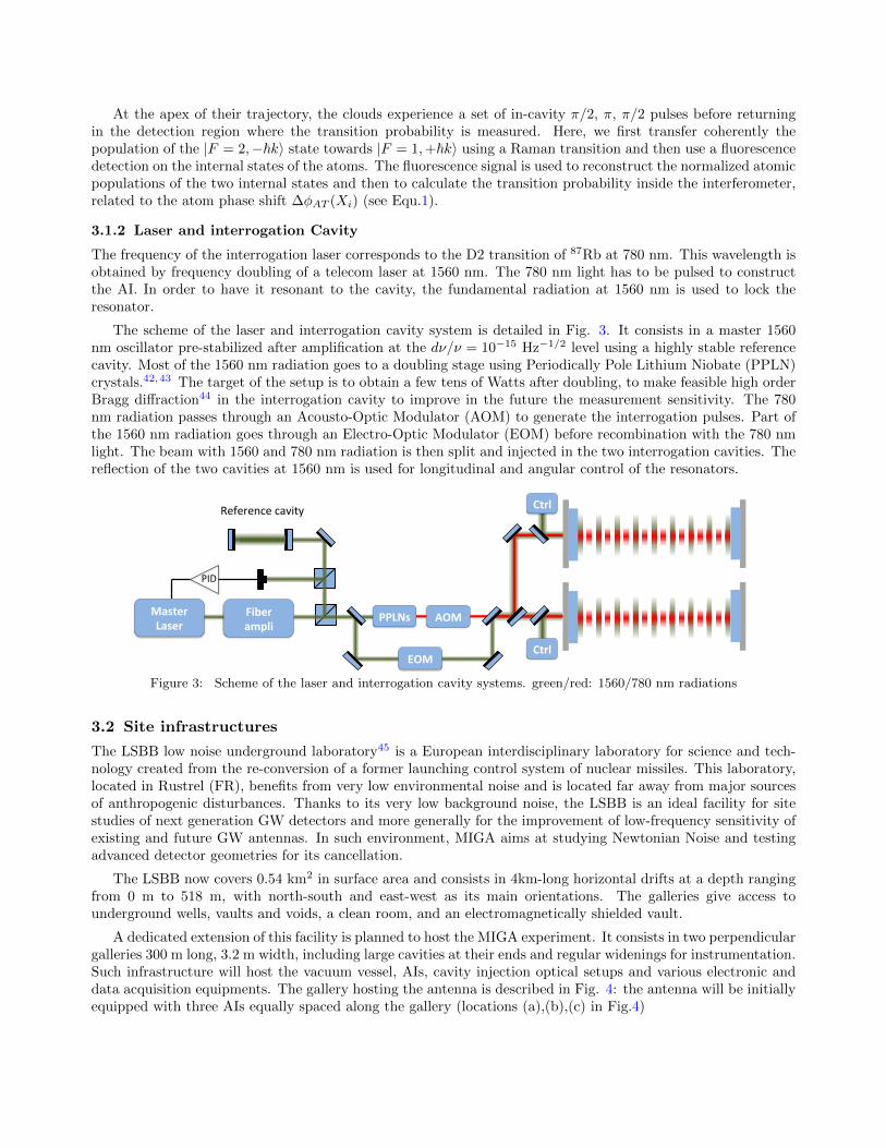
The scheme of the laser and interrogation cavity system is detailed in Fig. 3. It consists in a master 1560nm oscillator pre-stabilized after amplification at the dν/ν = 10−15 Hz−1/2 level using a highly stable referencecavity. Most of the 1560 nm radiation goes to a doubling stage using Periodically Pole Lithium Niobate (PPLN)crystals.42,43 The target of the setup is to obtain a few tens of Watts after doubling, to make feasible high orderBragg diffraction44 in the interrogation cavity to improve in the future the measurement sensitivity. The 780nm radiation passes through an Acousto-Optic Modulator (AOM) to generate the interrogation pulses. Part ofthe 1560 nm radiation goes through an Electro-Optic Modulator (EOM) before recombination with the 780 nmlight. The beam with 1560 and 780 nm radiation is then split and injected in the two interrogation cavities. Thereflection of the two cavities at 1560 nm is used for longitudinal and angular control of the resonators.
Master Laser
Fiber ampli
PPLNs
PID
AOM
EOM
Ctrl
Ctrl
Reference cavity
Figure 3: Scheme of the laser and interrogation cavity systems. green/red: 1560/780 nm radiations
3.2 Site infrastructures
The LSBB low noise underground laboratory45 is a European interdisciplinary laboratory for science and tech-nology created from the re-conversion of a former launching control system of nuclear missiles. This laboratory,located in Rustrel (FR), benefits from very low environmental noise and is located far away from major sourcesof anthropogenic disturbances. Thanks to its very low background noise, the LSBB is an ideal facility for sitestudies of next generation GW detectors and more generally for the improvement of low-frequency sensitivity ofexisting and future GW antennas. In such environment, MIGA aims at studying Newtonian Noise and testingadvanced detector geometries for its cancellation.
The LSBB now covers 0.54 km2 in surface area and consists in 4km-long horizontal drifts at a depth rangingfrom 0 m to 518 m, with north-south and east-west as its main orientations. The galleries give access tounderground wells, vaults and voids, a clean room, and an electromagnetically shielded vault.
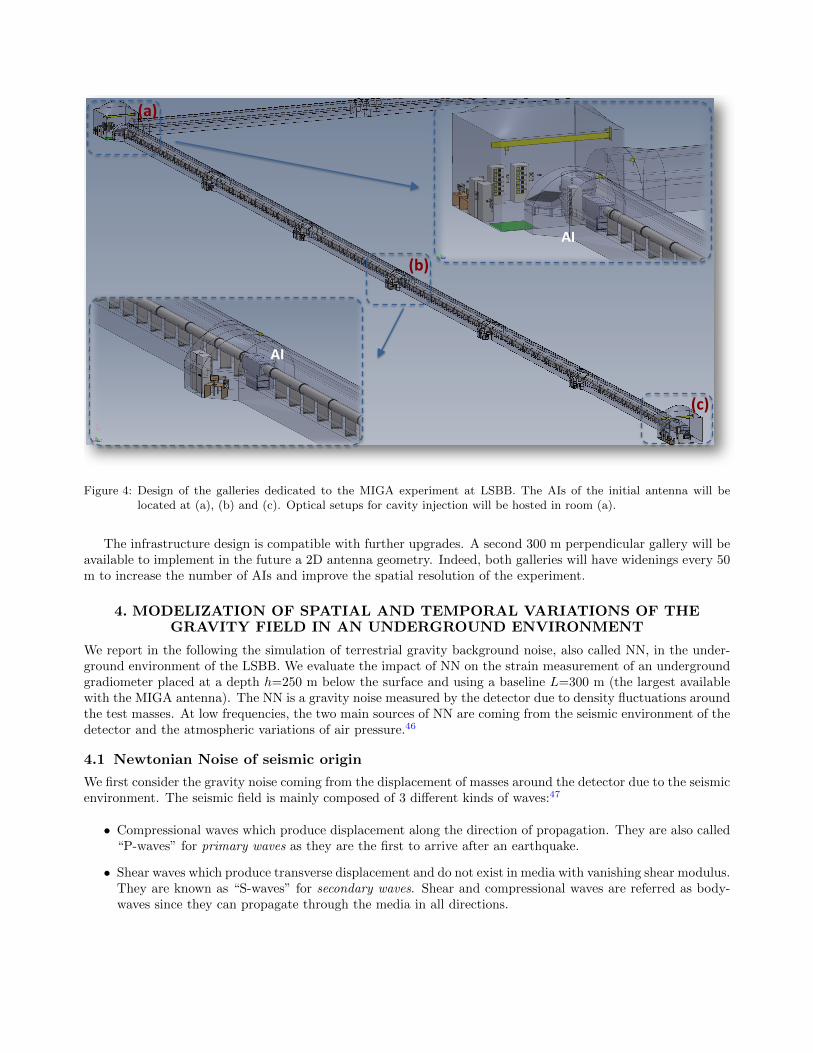
A dedicated extension of this facility is planned to host the MIGA experiment. It consists in two perpendiculargalleries 300 m long, 3.2 m width, including large cavities at their ends and regular widenings for instrumentation.Such infrastructure will host the vacuum vessel, AIs, cavity injection optical setups and various electronic anddata acquisition equipments. The gallery hosting the antenna is described in Fig. 4: the antenna will be initiallyequipped with three AIs equally spaced along the gallery (locations (a),(b),(c) in Fig.4)
AI
AI
(a)
(c)
(b)
Figure 4: Design of the galleries dedicated to the MIGA experiment at LSBB. The AIs of the initial antenna will belocated at (a), (b) and (c). Optical setups for cavity injection will be hosted in room (a).
The infrastructure design is compatible with further upgrades. A second 300 m perpendicular gallery will beavailable to implement in the future a 2D antenna geometry. Indeed, both galleries will have widenings every 50m to increase the number of AIs and improve the spatial resolution of the experiment.
4. MODELIZATION OF SPATIAL AND TEMPORAL VARIATIONS OF THEGRAVITY FIELD IN AN UNDERGROUND ENVIRONMENT
We report in the following the simulation of terrestrial gravity background noise, also called NN, in the under-ground environment of the LSBB. We evaluate the impact of NN on the strain measurement of an undergroundgradiometer placed at a depth h=250 m below the surface and using a baseline L=300 m (the largest availablewith the MIGA antenna). The NN is a gravity noise measured by the detector due to density fluctuations aroundthe test masses. At low frequencies, the two main sources of NN are coming from the seismic environment of thedetector and the atmospheric variations of air pressure.46
4.1 Newtonian Noise of seismic origin
We first consider the gravity noise coming from the displacement of masses around the detector due to the seismicenvironment. The seismic field is mainly composed of 3 different kinds of waves:47
• Compressional waves which produce displacement along the direction of propagation. They are also called“P-waves” for primary waves as they are the first to arrive after an earthquake.
• Shear waves which produce transverse displacement and do not exist in media with vanishing shear modulus.They are known as “S-waves” for secondary waves. Shear and compressional waves are referred as body-waves since they can propagate through the media in all directions.

k�x
y
z
kz ktotek
ez
Figure 5: Scheme of the system of coordinates
• Surface waves which include Love and Rayleigh wavetrains for teleseismic distances. If we consider ahomogeneous medium then only Rayleigh waves can propagate on its surface and below few tens of a hertz,these waves are known to be the dominant contribution to the seismic noise.48
As MIGA is an underground detector sensitive only to frequencies under a few Hertz, we can consider in firstapproximation only Rayleigh waves as a source for seismic noise in our system. For simplicity, we consider thecase of Rayleigh waves propagating on a homogeneous half space along a horizontal direction ~ek. The directionnormal to the surface corresponds to the z-axis of the coordinate system as shown in Fig. 5. A wavevector ~kcan be split into its vertical ~kz and horizontal components ~k% so that the three-dimensional displacement fieldof a Rayleigh wave reads
~ξ(~r, t) = ξk(~r, t)~ek + ξz(~r, t)~ez. (4)
This displacement field induces a fluctuation of the density of the medium around the test mass of the detector.This density fluctuation creates a gravity perturbation responsible for the so-called seismic NN on the test mass.To calculate this perturbation, we have to express the continuity equation on the density fluctuation which canbe written in the form
δρ(~r, t) = −∇ ·(ρ(~r)~ξ(~r, t)
), (5)
where we assumed that the seismic density perturbations are much smaller than the unperturbed densityδρ(~r, t) � ρ(~r), so that self-induced seismic scattering is insignificant. The corresponding perturbation of localacceleration can be written as
δ~a(~r0, t) = −G∫
dV∇0δρ(~r, t)
|~r − ~r0|
= −G∫
dV ρ(~r)(~ξ(~r, t) · ∇0
) ~r − ~r0|~r − ~r0|3
= G
∫dV ρ(~r)
1
|~r − ~r0|3(~ξ(~r, t)− 3(~err0 · ~ξ(~r, t))~err0
),
(6)
with ~err0 ≡ (~r − ~r0)/|~r − ~r0| and ∇0 denotes the gradient operation with respect to ~r0. To estimate the NNon the detector, we calculated the explicit solution of the integral (6) for plane seismic waves of the form~ξ(~r, t) = ξ0e
i(~k·~r−ωt)~ek. This calculation gives in cartesian coordinates
δ~a(~r0, t) = 2πGρ0ξze−hk%ei(
~k%·~%0−ωt)γ
i cosφi sinφ−1
, (7)
where φ is the angle of propagation with respect to the x-axis and γ is a dimensionless factor depending on theelastic properties of the half-space.49 The noise density of differential acceleration along a baseline of length Lparallel to the x-axis reads
S(δ~a(L~ex)− δ~a(~0);ω
)=(2πGρ0e
−hk%γ)2S(ξz;ω)
1− 2J0(k%L) + 2J1(k%L)/(k%L)1− 2J1(k%L)/(k%L)
2− 2J0(k%L)
, (8)
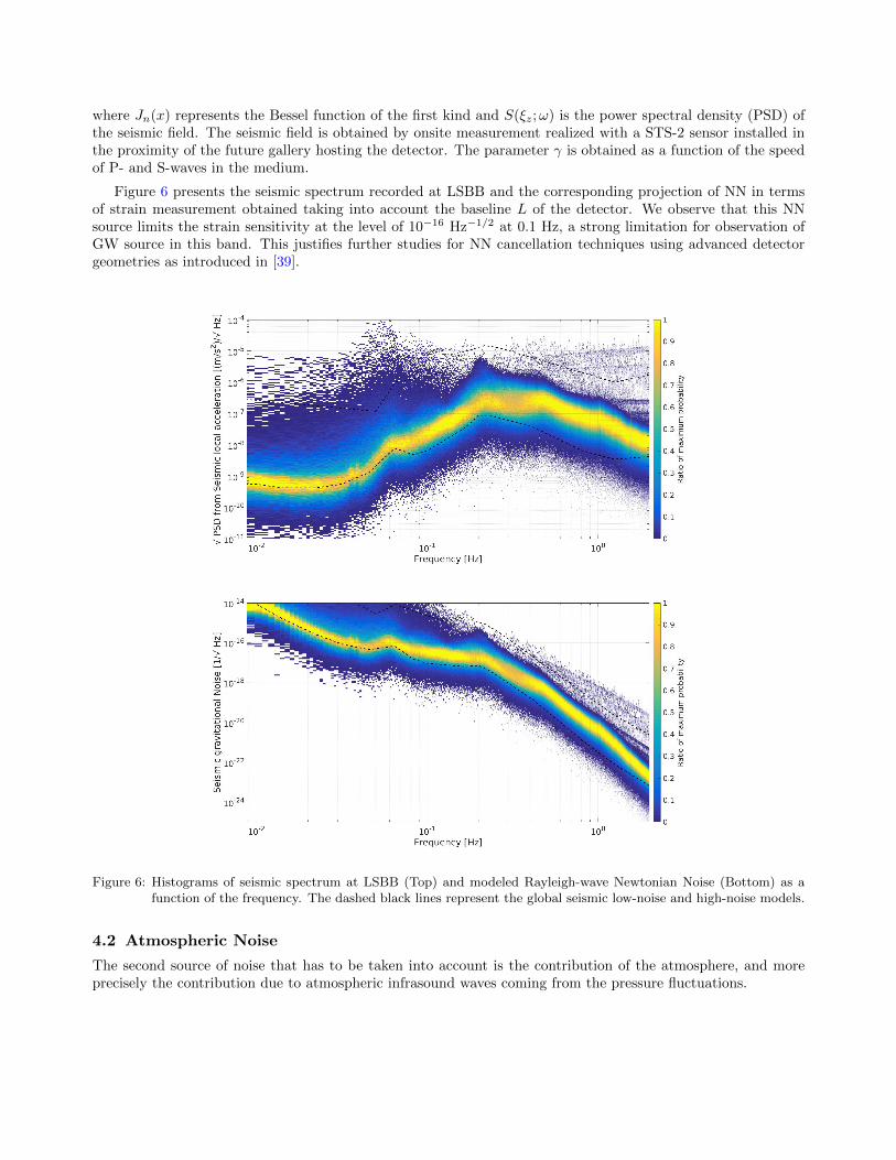
where Jn(x) represents the Bessel function of the first kind and S(ξz;ω) is the power spectral density (PSD) ofthe seismic field. The seismic field is obtained by onsite measurement realized with a STS-2 sensor installed inthe proximity of the future gallery hosting the detector. The parameter γ is obtained as a function of the speedof P- and S-waves in the medium.
Figure 6 presents the seismic spectrum recorded at LSBB and the corresponding projection of NN in termsof strain measurement obtained taking into account the baseline L of the detector. We observe that this NNsource limits the strain sensitivity at the level of 10−16 Hz−1/2 at 0.1 Hz, a strong limitation for observation ofGW source in this band. This justifies further studies for NN cancellation techniques using advanced detectorgeometries as introduced in [39].
Figure 6: Histograms of seismic spectrum at LSBB (Top) and modeled Rayleigh-wave Newtonian Noise (Bottom) as afunction of the frequency. The dashed black lines represent the global seismic low-noise and high-noise models.
4.2 Atmospheric Noise
The second source of noise that has to be taken into account is the contribution of the atmosphere, and moreprecisely the contribution due to atmospheric infrasound waves coming from the pressure fluctuations.
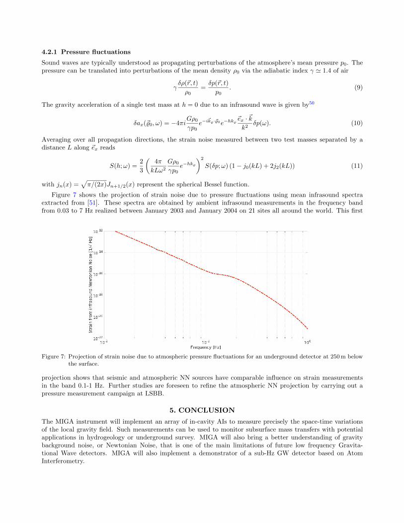
4.2.1 Pressure fluctuations
Sound waves are typically understood as propagating perturbations of the atmosphere’s mean pressure p0. Thepressure can be translated into perturbations of the mean density ρ0 via the adiabatic index γ ' 1.4 of air
γδρ(~r, t)
ρ0=δp(~r, t)
p0. (9)
The gravity acceleration of a single test mass at h = 0 due to an infrasound wave is given by50
δax(~%0, ω) = −4πiGρ0γp0
e−i~k%·~%0e−hk%
~ex · ~kk2
δp(ω). (10)
Averaging over all propagation directions, the strain noise measured between two test masses separated by adistance L along ~ex reads
S(h;ω) =2
3
(4π
kLω2
Gρ0γp0
e−hk%)2
S(δp;ω) (1− j0(kL) + 2j2(kL)) (11)
with jn(x) =√π/(2x)Jn+1/2(x) represent the spherical Bessel function.
Figure 7 shows the projection of strain noise due to pressure fluctuations using mean infrasound spectraextracted from [51]. These spectra are obtained by ambient infrasound measurements in the frequency bandfrom 0.03 to 7 Hz realized between January 2003 and January 2004 on 21 sites all around the world. This first
Figure 7: Projection of strain noise due to atmospheric pressure fluctuations for an underground detector at 250 m belowthe surface.
projection shows that seismic and atmospheric NN sources have comparable influence on strain measurementsin the band 0.1-1 Hz. Further studies are foreseen to refine the atmospheric NN projection by carrying out apressure measurement campaign at LSBB.
5. CONCLUSION
The MIGA instrument will implement an array of in-cavity AIs to measure precisely the space-time variationsof the local gravity field. Such measurements can be used to monitor subsurface mass transfers with potentialapplications in hydrogeology or underground survey. MIGA will also bring a better understanding of gravitybackground noise, or Newtonian Noise, that is one of the main limitations of future low frequency Gravita-tional Wave detectors. MIGA will also implement a demonstrator of a sub-Hz GW detector based on AtomInterferometry.

In this paper, we presented the first projection of Newtonian Noise on the strain sensitivity of MIGA gradiome-ters and showed limitations of strain measurements at the level of 10−16 Hz−1/2 at 0.1 Hz. Precise knowledgeof such noise is mandatory for determining advanced detector geometries and measurement methods for NNrejection and low frequency GW detection. Indeed, the MIGA project aims to be the very first step towards therealization of a future European infrastructure for GW observation based on advanced quantum technologies.
ACKNOWLEDGMENTS
This work was realized with the financial support of the French State through the “Agence Nationale de laRecherche” (ANR) in the frame of the “Investissement d’avenir” programs: IdEx Bordeaux - LAPHIA (ANR-10-IDEX-03-02) and Equipex MIGA (ANR-11-EQPX-0028). This work was also supported by Conseil Regionald’Aquitaine (project Alisios contract number 20131603010) and by the city of Paris (Emergence project HSENS-MWGRAV). Author G. L. thanks DGA for financial support.
REFERENCES
[1] Chu, S., Cohen-Tannoudji, C., and Phillips, W., [Nobel Lectures in Physics: 1996-2000 ], ch. (1997) fordevelopment of methods to cool and trap atoms with laser light, World Scientific Pub. Co. Inc. (2003).
[2] P. R. Berman (Ed.), [Atom Interferometry ], Academic Press, San Diego (1997).
[3] Carnal, O. and Mlynek, J., “Young’s double-slit experiment with atoms: A simple atom interferometer,”Phys. Rev. Lett. 66, 2689 (1991).
[4] Keith, D. W., Ekstrom, C. R., Turchette, Q. R., and Pritchard, D. E., “An Interferometer for Atoms,”Phys. Rev. Lett. 66, 2693 (1991).
[5] Riehle, F., Kisters, T., Witte, A., Helmcke, J., and Borde, C. J., “Optical Ramsey spectroscopy in a rotatingframe: Sagnac effect in a matter-wave interferometer,” Phys. Rev. Lett. 67, 177 (1991).
[6] Kasevich, M. and Chu, S., “Atomic interferometry using stimulated Raman transitions,” Phys. Rev. Lett. 67,181 (1991).
[7] Barrett, B., Bertoldi, A., and Bouyer, P., “Inertial quantum sensors using light and matter.”arXiv:1603.03246 [physics.atom-ph].
[8] Peters, A., Chung, K. Y., and Chu, S., “High-precision gravity measurements using atom interferometry,”Metrologia 38, 25 (2001).
[9] Snadden, M. J., McGuirk, J. M., Bouyer, P., Haritos, K. G., and Kasevich, M. A., “Measurement of theearth’s gravity gradient with an atom interferometer-based gravity gradiometer,” Phys. Rev. Lett. 81, 971(1998).
[10] Gustavson, T., Bouyer, P., and Kasevich, M., “Precision rotation measurements with an atom interferometergyroscope,” Phys. Rev. Lett. 78, 2046 (1997).
[11] Canuel, B., Leduc, F., Holleville, D., Gauguet, A., Fils, J., Virdis, A., Clairon, A., Dimarcq, N., Borde,C. J., Landragin, A., and Bouyer, P., “Six-axis inertial sensor using cold-atom interferometry,” Phys. Rev.Lett. 97, 010402 (2016).
[12] Fixler, J. B., Foster, G. T., McGuirk, J. M., and Kasevich, M. A., “Atom interferometer measurement ofthe Newtonian constant of gravity,” Science 315, 74 (2007).
[13] Rosi, G., Sorrentino, F., Cacciapuoti, L., Prevedelli, M., and Tino, G., “Precision measurement of theNewtonian gravitational constant using cold atoms,” Nature 510, 518 (2014).
[14] Bouchendira, R., Clade, P., Guellati-Khelifa, S., Nez, F., and Biraben, F., “New determination of the finestructure constant and test of the quantum electrodynamics,” Phys. Rev. Lett. 106, 080801 (2011).
[15] Fray, S., Diez, C. A., Hansch, T. W., and Weitz, M., “Atomic Interferometer with Amplitude Gratings ofLight and Its Applications to Atom Based Tests of the Equivalence Principle,” Phys. Rev. Lett. 93, 240404(2004).
[16] Schlippert, D., Hartwig, J., Albers, H., Richardson, L. L., Schubert, C., Roura, A., Schleich, W. P., Ertmer,W., and Rasel, E. M., “Quantum test of the universality of free fall,” Phys. Rev. Lett. 112, 203002 (2014).

[17] Barrett, B., Antoni-Micollier, L., Chichet, L., Battelier, B., Gominet, P., Bertoldi, A., Bouyer, P., andLandragin, A., “Correlative methods for dual-species quantum tests of the weak equivalence principle,”New J. Phys. 17, 085010 (2015).
[18] Zhou, L., Long, S., Tang, B., Chen, X., Gao, F., Peng, W., Duan, W., Zhong, J., Xiong, Z., Wang, J.,Zhang, Y., and Zhan, M., “Test of equivalence principle at 10−8 level by a dual-species double-diffractionraman atom interferometer,” Phys. Rev. Lett. 115, 013004 (2015).
[19] Bonnin, A., Zahzam, N., Bidel, Y., and Bresson, A., “Characterization of a simultaneous dual-species atominterferometer for a quantum test of the weak equivalence principle,” Phys. Rev. A 92, 023626 (2015).
[20] Aguilera, D. et al., “STE-QUEST test of the universality of free fall using cold atom interferometry,” Class.Quantum Grav. 31, 115010 (2014).
[21] Hartwig, J., Abend, S., Schubert, C., Schlippert, D., Ahlers, H., Posso-Trujillo, K., Gaaloul, N., Ertmer,W., and Rasel, E. M., “Testing the universality of free fall with rubidium and ytterbium in a very largebaseline atom interferometer,” New J. Phys. 17, 035011 (2015).
[22] Arvanitaki, A., Dimopoulos, S., Geraci, A. A., Hogan, J., and Kasevich, M., “How to test atom and neutronneutrality with atom interferometry,” Phys. Rev. Lett. 100, 120407 (2008).
[23] Burrage, C., Copeland, E. J., and Hinds, E. A., “Probing dark energy with atom interferometry,” J. Cosmol.Astropart. Phys. 2015, 42 (2015).
[24] Hamilton, P., Jaffe, M., Haslinger, P., Simmons, Q., Muller, H., and Khoury, J., “Atom-interferometryconstraints on dark energy,” Science 349, 849 (2015).
[25] Dimopoulos, S., Graham, P. W., Hogan, J. M., Kasevich, M. A., and Rajendran, S., “Gravitational wavedetection with atom interferometry,” Phys. Lett. B 678, 37 (2009).
[26] Hogan, J. M., Johnson, D. M. S., Dickerson, S., Kovachy, T., Sugarbaker, A., Chiow, S.-w., Graham, P. W.,Kasevich, M. A., Saif, B., Rajendran, S., Bouyer, P., Seery, B. D., Feinberg, L., and Keski-Kuha, R., “Anatomic gravitational wave interferometric sensor in low earth orbit (AGIS-LEO),” General Relativity andGravitation 43, 1953 (2011).
[27] Yu, N. and Tinto, M., “Gravitational wave detection with single-laser atom interferometers,” Gen. Relativ.and Gravit. 43, 1943 (2011).
[28] Graham, P. W., Hogan, J. M., Kasevich, M. A., and Rajendran, S., “New method for gravitational wavedetection with atomic sensors,” Phys. Rev. Lett. 110, 171102 (2013).
[29] Hogan, J. M. and Kasevich, M. A., “Atom interferometric gravitational wave detection using heterodynelaser links.” arXiv:1501.06797 [physics.atom-ph].
[30] Chiow, S.-w., Williams, J., and Yu, N., “Laser-ranging long baseline differential atom interferometers forspace.” arXiv:1502.00047 [physics.atom-ph].
[31] Harms, J., Slagmolen, B., Adhikari, R., Miller, M., Evans, M., Chen, Y., Muller, H., and Ando, M., “Low-frequency terrestrial gravitational-wave detectors,” Phys. Rev. D 88, 122003 (2013).
[32] Abbott, B., Abbott, R., Abbott, T., Abernathy, M., Acernese, F., Ackley, K., Adams, C., Adams, T.,Addesso, P., Adhikari, R., et al., “Observation of gravitational waves from a binary black hole merger,”Phys. Rev. Lett. 116, 061102 (2016).
[33] Moore, C., Cole, R. H., and Berry, C., “Gravitational-wave sensitivity curves,” Class. Quantum Grav. 32,015014 (2014).
[34] Canuel, B., Amand, L., Bertoldi, A., Chaibi, W., Geiger, R., Gillot, J., Landragin, A., Merzougui, M., Riou,I., Schmid, S. P., and Bouyer, P., “The matter-wave laser interferometer gravitation antenna (MIGA): Newperspectives for fundamental physics and geosciences,” E3S Web of Conferences 4, 01004 (2014).
[35] Geiger, R., Amand, L., Bertoldi, A., Canuel, B., Chaibi, W., Danquigny, C., Dutta, I., Fang, B., Gaffet,S., Gillot, J., Holleville, D., Landragin, A., Merzougui, M., Riou, I., Savoie, D., and Bouyer, P., “Matter-wave laser interferometric gravitation antenna (MIGA): New perspectives for fundamental physics andgeosciences,” in [Proceedings of the 50th Rencontres de Moriond, 100 years after GR ], 163 (2015).
[36] Dimopoulos, S., Graham, P., Hogan, J., Kasevich, M., and Rajendran, S., “Atomic gravitational waveinterferometric sensor,” Phys. Rev. D 78, 122002 (2008).
[37] Martin, P., Oldaker, B., Miklich, A., and Pritchard, D., “Bragg scattering of atoms from a standing lightwave,” Phys. Rev. Lett. 60, 515 (1988).
[38] Sorrentino, F., Bodart, Q., Cacciapuoti, L., Lien, Y.-H., Prevedelli, M., Rosi, G., Salvi, L., and Tino,G. M., “Sensitivity limits of a Raman atom interferometer as a gravity gradiometer,” Phys. Rev. A 89,023607 (2014).
[39] Chaibi, W., Geiger, R., Canuel, B., Bertoldi, A., Landragin, A., and Bouyer, P., “Low frequency gravita-tional wave detection with ground-based atom interferometer arrays,” Phys. Rev. D. 93, 021101 (2016).
[40] Cheinet, P., Canuel, B., Pereira Dos Santos, F., Gauguet, A., Yver-Leduc, F., and Landragin, A., “Mea-surement of the sensitivity function in a time-domain atomic interferometer,” IEEE T. Instrum. Meas. 57,1141 (2008).
[41] Le Gouet, J., Cheinet, P., Kim, J., Holleville, D., Clairon, A., Landragin, A., and Pereira Dos Santos, F.,“Influence of lasers propagation delay on the sensitivity of atom interferometers,” The European PhysicalJournal D 44, 419 (2007).
[42] Chiow, S.-w., Kovachy, T., Hogan, J. M., and Kasevich, M. A., “Generation of 43W of quasi-continuous780nm laser light via high-efficiency, single-pass frequency doubling in periodically poled lithium niobatecrystals,” Opt. Lett. 37, 3861 (2012).
[43] Sane, S. S., Bennetts, S., Debs, J. E., Kuhn, C. C. N., McDonald, G. D., Altin, P. A., Close, J. D.,and Robins, N. P., “11 w narrow linewidth laser source at 780 nm for laser cooling and manipulation ofrubidium,” Opt. Express 20(8), 8915 (2012).
[44] Giltner, D. M., McGowan, R. W., and Lee, S. A., “Theoretical and experimental study of the Braggscattering of atoms from a standing light wave,” Phys. Rev. A 52, 3966 (1995).
[45] http://www.lsbb.eu/index.php/fr/. LSBB website.
[46] Saulson, P. R., “Terrestrial gravitational noise on a gravitational wave antenna,” Phys. Rev. D 30, 732(1984).
[47] Aki, K. and Richards, P. G., [Quantitative Seismology ], University Science Books, Sausalito, CA (2009).
[48] Bonnefoy-Claudet, S., Cotton, F., and Bard, P., “The nature of noise wavefield and its applications for siteeffects studies - a literature review,” Earth Sci. Rev. 79, 205 (2006).
[49] Harms, J., “Terrestrial gravity fluctuations,” Living Rev. Relativity 18, 3 (2015).
[50] Creighton, T., “Tumbleweeds and airborne gravitational noise sources for ligo,” Class. Quantum Grav. 25,125011 (2008).
[51] Bowman, J. R., Baker, G. E., and Bahavar, M., “Ambient infrasound noise,” Geophys. Res. Lett. 32, L09803(2005).