midwest time control, inc.2017-3-6 · midwest time control, inc. master clock systems...
TRANSCRIPT
MidWest Time Control, Inc.
Master Clock SystemsApplication
Guide
P.O. Box 1108 Phone: 918-272-9430Owasso, OK 74055 FAX: 918-272-9441
www.midwest-time.com [email protected]

TABLE OF CONTENTS PAGE #
GENERAL, MASTER CLOCK SYSTEMS 1
WALL CLOCKS 2
IMPULSE CLOCKS 2
WIRED SYNCHRONOUS CLOCKS 5
ELECTRONIC SYNCHRONOUS CLOCKS 5
DIGITAL CLOCKS 6
WIRING CONSIDERATIONS 7
MINUTE IMPULSE SYSTEM WIRING 7
WIRED SYNCHRONOUS SYSTEM WIRING 8
BOOSTERS 8
MASTER CLOCKS 9
OTHER MASTER CLOCK OPTIONS 9
FIGURE PAGE #
1. MINUTE IMPULSE CLOCK MOVEMENT 2
2. SIMPLIFIED 2 WIRE IMPULSE MOVEMENT SCHEMATIC 3
3. SIMPLIFIED 3 WIRE IMPULSE MOVEMENT SCHEMATIC 3
4. 3 WIRE IMPULSE MOVEMENT SCHEMATIC 3
5. 2 WIRE, REVERSE POLARITY, IMPULSE MOVEMENT SCHEMATIC 4
6. WIRED SYNCHRONOUS CLOCK MOVEMENT 5
7. WIRE RESISTANCE BY WIRE SIZE 7
8. BOOSTER WIRING DIAGRAM 8
9. SYNCHRONIZED POWER GRID 11

11
Master Clock(MTC-200, MTC-400, or MTC-600)
3:00
AnalogClocks
(ASC Series)(DSC Series)
ClocksDigital
PayrollRecorders**
Time & Attendance System **
HVAC Control
Bells**
Lighting Control
** Manufactured By Others
Time & Attendance System **
Data Collection System **(RS232 or RS485)
Computer
(RS
232 o
r R
S485)
NIST Modem Clock
DIAL
S M T T SFW
HI SPEC
DST
MASTER CLOCK SYSTEMS
Central to any building time control system is a Master Clock. A Master Clock will provide a time base forsynchronizing all of the time related functions in a building or building complex. With a central time base,all time sensitive functions in the building will be in unison. As an example, the Wall Clocks will besynchronized with the bells, the payroll system, the computers, the lighting controls, the security system, Etc.Operations in a building with a central time base are usually much more coordinated even though mostpeople within the building are unaware of its existence.
Wall Clocks are generally the first and most visible indication of a synchronized or master clock system. Allwall clocks will indicate the same time of day.
Master Clock Systems can be very simple or as sophisticated as the customer requires. A very simplesystem could be only synchronized Wall Clocks or only automatic ringing of Bells.
A more sophisticated system may include both Wall Clocks and automatic bell control. It could also includesynchronizing Payroll Recorders, Time Stamps, Data Collection Systems, and Computerized Time &Attendance Systems.
A modern Master Clock System can also be used to perform functions which historically were not includedin Clock Systems; Turn on lighting, turn on Security Systems, Heating and Air Conditioning systems.
22
Figure 1Minute Impulse Clock Movement
WALL CLOCKS
Through the years, the Master Clock System has evolved through a great number of different schemes forcorrecting Wall Clocks, and many older systems are still in operation. For purposes of expediency, thisdiscussion will primarily focus on the most common wall clocks used in new installations.
In Analog or Dial type system Wall Clocks, there are basically two types, the Minute Impulse andSynchronous Motor. There is no best type, each has both advantages and disadvantages. The End User'srequirement will generally determine the choice for any particular installation.
Digital Clocks have a growing acceptance in Clock System applications. They are very easily read by acasual observation, they are self illuminating and long lasting. Digital Clocks may be installed andintermixed with most existing analog clock systems.
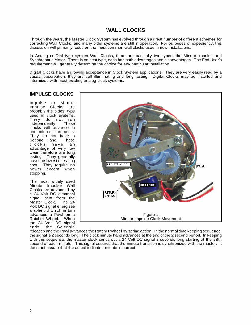
IMPULSE CLOCKS
Impulse or MinuteImpulse Clocks areprobably the oldest typeused in clock systems.They do not runindependently. Theseclocks will advance inone minute increments.They do not have aSecond Hand. Thesec l o c k s h a v e a nadvantage of very lowwear therefore are longlasting. They generallyhave the lowest operatingcost. They require nopower except whenstepping.
The most widely usedMinute Impulse WallClocks are advanced bya 24 Volt DC electricalsignal sent from theMaster Clock. The 24Volt DC signal energizesa solenoid which in turnadvances a Pawl on aRatchet Wheel. Whenthe 24 Volt DC signalends, the Solenoidreleases and the Pawl advances the Ratchet Wheel by spring action. In the normal time keeping sequence,the signal is 2 seconds long. The clock minute hand advances at the end of the 2 second period. In keepingwith this sequence, the master clock sends out a 24 Volt DC signal 2 seconds long starting at the 58thsecond of each minute. This signal assures that the minute transition is synchronized with the master. Itdoes not assure that the actual indicated minute is correct.

33
Figure 2 - SIMPLIFIED 2 WIREIMPULSE MOVEMENT SCHEMATIC
Figure 3 - SIMPLIFIED 3 WIREIMPULSE MOVEMENT SCHEMATIC
NO Contact opens hourly atthe 59th Minute and Closes 1Minute after the hour.
NONC
CWhiteA
BlackB
RedC
Figure 4 - 3 WIRE IMPULSEMOVEMENT SCHEMATIC
Figure 2 is a schematic representation of a minuteimpulse clock movement. Notice that a switch contactis in series with the Ratchet Solenoid. If we cause thatswitch to open, the 24 Volt DC signal could no longerreach the Solenoid and thus the clock would stop at thepoint the switch was opened.
Figure 3 is the same as Figure 2 except a third wire isconnected to the Normally Closed (NC) contact of theswitch. If we cause a 24 Volt DC signal to be applied tothe third wire at the time we are ready for the clock torestart, we can control the precise time to start and thuscause all clocks in the system to be at the same pointon the dial and advance in unison.
Figure 4 is a schematic representation of an actualminute impulse clock movement. The three wires areidentified as "A", "B" & "C". The "C" wire is common.The normal time keeping signal from the Master Clockis applied to the "A" wire each minute. The switchcontact is operated by a cam which is part of the ratchetand gear attached to the minute hand. At the 59thminute, the cam causes the switch contact to transferfrom the normally open (NO) to the normally closed(NC) contact. If the wall clock is fast, it will stop at the59th minute. During the 59th minute, the master clocksends 25 rapid 24 Volt DC signals on the "A" wire. Ifthe wall clock is slow, these 25 fast signals will advancethe minute hand until the switch contact opens (59thMinute). When the Master Clock time is at 59:58, the24 Volt DC signal is sent on the "B" wire. This signalwill cause the minute hand to advance to the 00 minute.This sequence synchronizes the Minute Hand with Master Clock.
In practical Master Clocks, the 24 Volt DC signal is placed on both the "A" and "B" wire for the 00 Minute untilthe next 49th minute transition. The signal is applied to the "A" wire only from the 50th to the 59th minutetransition. With this sequence, the minute hand can be corrected to the precise minute if it is less than 10minutes fast or 25 minutes slow.
This clock is usually referred to in the industry as a 3 Wire 59th Minute Impulse Clock.
This clock is MidWest Time Control Model ASC-4-xxx.
44
NO Contact opens hourly atthe 59th Minute and Closes 1Minute after the hour.
White
Red
PC
AB
NO
NCC
Figure 5 - 2 WIRE, REVERSE POLARITY,MINUTE IMPULSE MOVEMENT SCHEMATIC
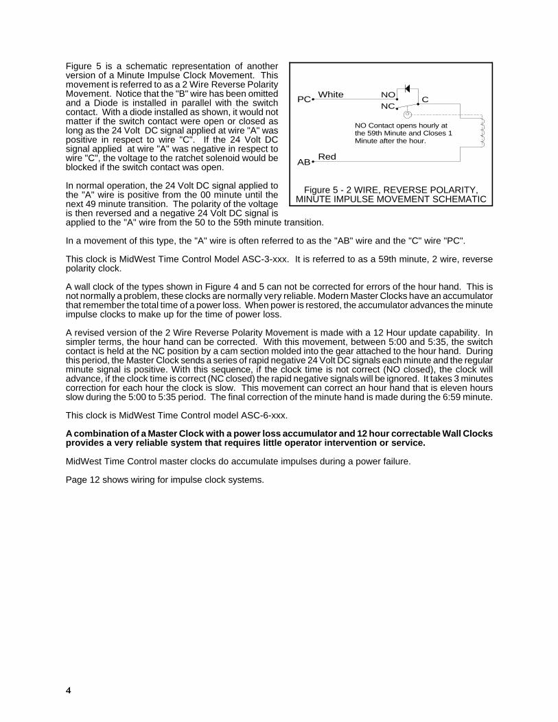
Figure 5 is a schematic representation of anotherversion of a Minute Impulse Clock Movement. Thismovement is referred to as a 2 Wire Reverse PolarityMovement. Notice that the "B" wire has been omittedand a Diode is installed in parallel with the switchcontact. With a diode installed as shown, it would notmatter if the switch contact were open or closed aslong as the 24 Volt DC signal applied at wire "A" waspositive in respect to wire "C". If the 24 Volt DCsignal applied at wire "A" was negative in respect towire "C", the voltage to the ratchet solenoid would beblocked if the switch contact was open.
In normal operation, the 24 Volt DC signal applied tothe "A" wire is positive from the 00 minute until thenext 49 minute transition. The polarity of the voltageis then reversed and a negative 24 Volt DC signal isapplied to the "A" wire from the 50 to the 59th minute transition.
In a movement of this type, the "A" wire is often referred to as the "AB" wire and the "C" wire "PC".
This clock is MidWest Time Control Model ASC-3-xxx. It is referred to as a 59th minute, 2 wire, reversepolarity clock.
A wall clock of the types shown in Figure 4 and 5 can not be corrected for errors of the hour hand. This isnot normally a problem, these clocks are normally very reliable. Modern Master Clocks have an accumulatorthat remember the total time of a power loss. When power is restored, the accumulator advances the minuteimpulse clocks to make up for the time of power loss.
A revised version of the 2 Wire Reverse Polarity Movement is made with a 12 Hour update capability. Insimpler terms, the hour hand can be corrected. With this movement, between 5:00 and 5:35, the switchcontact is held at the NC position by a cam section molded into the gear attached to the hour hand. Duringthis period, the Master Clock sends a series of rapid negative 24 Volt DC signals each minute and the regularminute signal is positive. With this sequence, if the clock time is not correct (NO closed), the clock willadvance, if the clock time is correct (NC closed) the rapid negative signals will be ignored. It takes 3 minutescorrection for each hour the clock is slow. This movement can correct an hour hand that is eleven hoursslow during the 5:00 to 5:35 period. The final correction of the minute hand is made during the 6:59 minute.
This clock is MidWest Time Control model ASC-6-xxx.
A combination of a Master Clock with a power loss accumulator and 12 hour correctable Wall Clocksprovides a very reliable system that requires little operator intervention or service.
MidWest Time Control master clocks do accumulate impulses during a power failure.
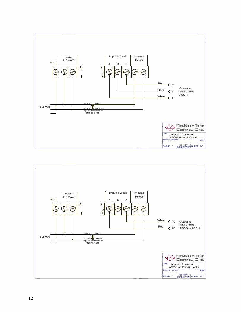
Page 12 shows wiring for impulse clock systems.
55
Figure 6 - WIRED SYNCHRONOUSCLOCK MOVEMENT
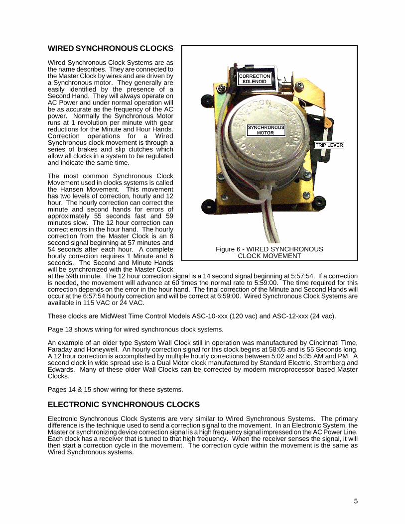
WIRED SYNCHRONOUS CLOCKS
Wired Synchronous Clock Systems are asthe name describes. They are connected tothe Master Clock by wires and are driven bya Synchronous motor. They generally areeasily identified by the presence of aSecond Hand. They will always operate onAC Power and under normal operation willbe as accurate as the frequency of the ACpower. Normally the Synchronous Motorruns at 1 revolution per minute with gearreductions for the Minute and Hour Hands.Correction operations for a WiredSynchronous clock movement is through aseries of brakes and slip clutches whichallow all clocks in a system to be regulatedand indicate the same time.
The most common Synchronous ClockMovement used in clocks systems is calledthe Hansen Movement. This movementhas two levels of correction, hourly and 12hour. The hourly correction can correct theminute and second hands for errors ofapproximately 55 seconds fast and 59minutes slow. The 12 hour correction cancorrect errors in the hour hand. The hourlycorrection from the Master Clock is an 8second signal beginning at 57 minutes and54 seconds after each hour. A completehourly correction requires 1 Minute and 6seconds. The Second and Minute Handswill be synchronized with the Master Clockat the 59th minute. The 12 hour correction signal is a 14 second signal beginning at 5:57:54. If a correctionis needed, the movement will advance at 60 times the normal rate to 5:59:00. The time required for thiscorrection depends on the error in the hour hand. The final correction of the Minute and Second Hands willoccur at the 6:57:54 hourly correction and will be correct at 6:59:00. Wired Synchronous Clock Systems areavailable in 115 VAC or 24 VAC.
These clocks are MidWest Time Control Models ASC-10-xxx (120 vac) and ASC-12-xxx (24 vac).
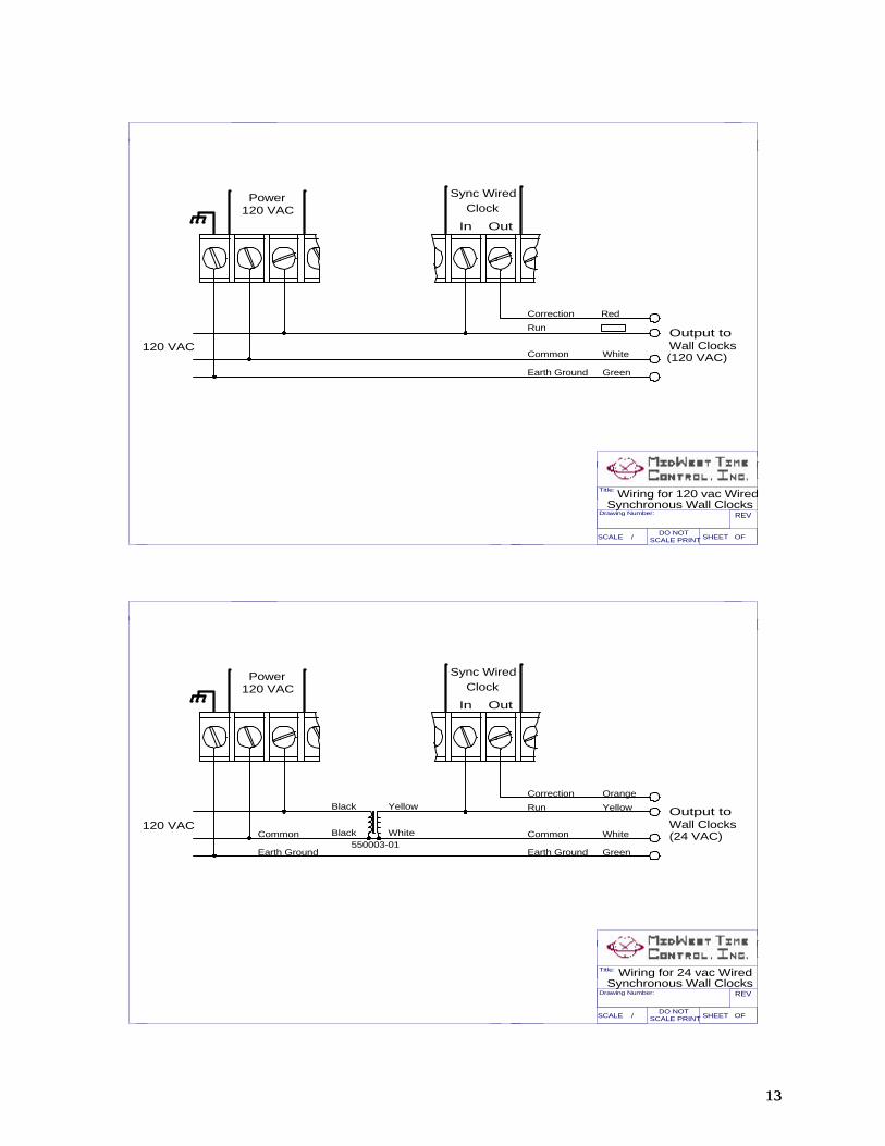
Page 13 shows wiring for wired synchronous clock systems.
An example of an older type System Wall Clock still in operation was manufactured by Cincinnati Time,Faraday and Honeywell. An hourly correction signal for this clock begins at 58:05 and is 55 Seconds long.A 12 hour correction is accomplished by multiple hourly corrections between 5:02 and 5:35 AM and PM. Asecond clock in wide spread use is a Dual Motor clock manufactured by Standard Electric, Stromberg andEdwards. Many of these older Wall Clocks can be corrected by modern microprocessor based MasterClocks.
Pages 14 & 15 show wiring for these systems.
ELECTRONIC SYNCHRONOUS CLOCKS
Electronic Synchronous Clock Systems are very similar to Wired Synchronous Systems. The primarydifference is the technique used to send a correction signal to the movement. In an Electronic System, theMaster or synchronizing device correction signal is a high frequency signal impressed on the AC Power Line.Each clock has a receiver that is tuned to that high frequency. When the receiver senses the signal, it willthen start a correction cycle in the movement. The correction cycle within the movement is the same asWired Synchronous systems.

66
DIGITAL CLOCKS
Digital Clocks provide a new dimension in Synchronized Clock Systems. They are generally electronic inoperation with no mechanical moving parts. They can be configured to operate in a Minute Impulse or WiredSynchronous system. In addition, they can be configured to be corrected from a low voltage data signal(RS485). The most common Digital Clocks are constructed with Red Light Emitting Diodes for the display.
Modern Digital Clocks used as system clocks are normally micro-processor based and can be programmedto perform many functions reserved for more conventional Master Clocks. The correction method and timecan be factory programmed to interface with many existing clock systems and computerized time andattendance systems.
Wired Synchronous Digital Clocks operate very similar to analog wired-synchronous clocks. The clockis continuously powered by the run voltage. When a correction signal of the proper time duration is received,the clock will set to the proper minute for an hourly correction or set the hours and minutes for a 12 hourcorrection. Most clocks of this type may be mixed with analog clocks of the same correction type withoutany problem.
MidWest Time Control manufactures a Digital Wall Clock with a relay output to correct Wired Synchronousclocks. This Clock may be used as a Master for Digital or Analog clocks.
Impulse Digital Clocks are only slightly more complicated to use. A digital clock requires continuous powerto light the display. A separate power source is required for these clocks. The impulse digital clocksmanufactured by MidWest Time Control will correct to most 2 or 3 wire impulse systems on the market. Theclocks run independent of the impulse system except during the correction sequence. These clocks use 2wires and are not polarity sensitive. From the above discussion on impulse clocks, you will recall that thereis a series of rapid impulses during the 59th minute of each hour. The digital clock will sense these rapidpulses and set xx:59. The master clock will stop these rapid pulses at the 50th second. The digital clockwill sense this dead period and wait for the next impulse. This next impulse is the 0 minute pulse. Thedigital clock will set to xx:00. The digital clock also resets the seconds and cycle counters to synchronizewith the master clock. The clock will accept impulses at any time except between 5:00 and 5:40. This allowsthe clock to be used on 12 hour correctable systems.
RS485 Correctable Digital Clocks provide a new dimension to synchronized clock systems. The clocksmanufactured by MidWest Time Control run independent until a signal is received. This signal is checkedfor proper protocol and correct data. The clock is then set to the time received. These clocks may besynchronized by a master clock, computer, or any other device capable of transmitting a RS485 signal.
MidWest Time Control manufactures a Digital Clock that is a master that sends out a RS485 signal to correctother digital clocks. This provides a very economical synchronized digital clock system.
MidWest Time Control has two series of Digital Clocks with 4" Digits (DSC-300-xxx and DSC-400-xxx).
77
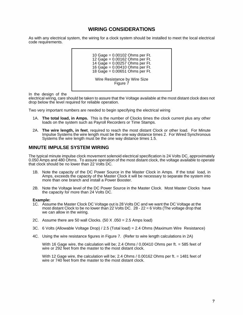
10 Gage = 0.00102 Ohms per Ft.12 Gage = 0.00162 Ohms per Ft.14 Gage = 0.00257 Ohms per Ft.16 Gage = 0.00410 Ohms per Ft.18 Gage = 0.00651 Ohms per Ft.
Wire Resistance by Wire SizeFigure 7
WIRING CONSIDERATIONS
As with any electrical system, the wiring for a clock system should be installed to meet the local electricalcode requirements.
In the design of theelectrical wiring, care should be taken to assure that the Voltage available at the most distant clock does notdrop below the level required for reliable operation.
Two very important numbers are needed to begin specifying the electrical wiring
1A. The total load, in Amps. This is the number of Clocks times the clock current plus any otherloads on the system such as Payroll Recorders or Time Stamps.
2A. The wire length, in feet, required to reach the most distant Clock or other load. For MinuteImpulse Systems the wire length must be the one way distance times 2. For Wired SynchronousSystems the wire length must be the one way distance times 1.5.
MINUTE IMPULSE SYSTEM WIRING
The typical minute impulse clock movement solenoid electrical specification is 24 Volts DC, approximately0.050 Amps and 480 Ohms. To assure operation of the most distant clock, the voltage available to operatethat clock should be no lower than 22 Volts DC.
1B. Note the capacity of the DC Power Source in the Master Clock in Amps. If the total load, inAmps, exceeds the capacity of the Master Clock it will be necessary to separate the system intomore than one branch and install a Power Booster.
2B. Note the Voltage level of the DC Power Source in the Master Clock. Most Master Clocks havethe capacity for more than 24 Volts DC.
Example:1C. Assume the Master Clock DC Voltage out is 28 Volts DC and we want the DC Voltage at the
most distant Clock to be no lower than 22 Volts DC. 28 - 22 = 6 Volts (The voltage drop thatwe can allow in the wiring.
2C. Assume there are 50 wall Clocks. (50 X .050 = 2.5 Amps load)
3C. 6 Volts (Allowable Voltage Drop) / 2.5 (Total load) = 2.4 Ohms (Maximum Wire Resistance)
4C. Using the wire resistance figures in Figure 7. (Refer to wire length calculations in 2A)
With 16 Gage wire, the calculation will be; 2.4 Ohms / 0.00410 Ohms per ft. = 585 feet ofwire or 292 feet from the master to the most distant clock.
With 12 Gage wire, the calculation will be; 2.4 Ohms / 0.00162 Ohms per ft. = 1481 feet ofwire or 740 feet from the master to the most distant clock.
88
Master
ClockClock Clock Clock
Impulse ImpulseImpulseWall Wall Wall
Booster
115VAC
Additional Clocksand Boosters
115VAC
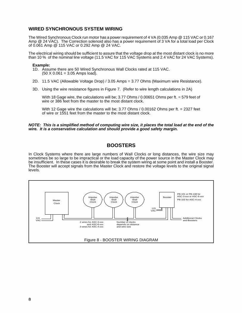
2 wires for ASC-3-xxxASC-6-xxxASC-4-xxx3 wires for
andNumber of clocksdepends on distanceand wire size
PB-101 or PB-108 forASC-3-xxx or ASC-6-xxx
PB-102 for ASC-4-xxx
Figure 8 - BOOSTER WIRING DIAGRAM
WIRED SYNCHRONOUS SYSTEM WIRING
The Wired Synchronous Clock run motor has a power requirement of 4 VA (0.035 Amp @ 115 VAC or 0.167Amp @ 24 VAC). The Correction solenoid also has a power requirement of 3 VA for a total load per Clockof 0.061 Amp @ 115 VAC or 0.292 Amp @ 24 VAC.
The electrical wiring should be sufficient to assure that the voltage drop at the most distant clock is no morethan 10 % of the nominal line voltage (11.5 VAC for 115 VAC Systems and 2.4 VAC for 24 VAC Systems).
Example:1D. Assume there are 50 Wired Synchronous Wall Clocks rated at 115 VAC.
(50 X 0.061 = 3.05 Amps load).
2D. 11.5 VAC (Allowable Voltage Drop) / 3.05 Amps = 3.77 Ohms (Maximum wire Resistance).
3D. Using the wire resistance figures in Figure 7. (Refer to wire length calculations in 2A)
With 18 Gage wire, the calculations will be; 3.77 Ohms / 0.00651 Ohms per ft. = 579 feet ofwire or 386 feet from the master to the most distant clock.
With 12 Gage wire the calculations will be; 3.77 Ohms / 0.00162 Ohms per ft. = 2327 feetof wire or 1551 feet from the master to the most distant clock.
NOTE: This is a simplified method of computing wire size, it places the total load at the end of thewire. It is a conservative calculation and should provide a good safety margin.
BOOSTERS
In Clock Systems where there are large numbers of Wall Clocks or long distances, the wire size maysometimes be so large to be impractical or the load capacity of the power source in the Master Clock maybe insufficient. In these cases it is desirable to break the system wiring at some point and install a Booster.The Booster will accept signals from the Master Clock and restore the voltage levels to the original signallevels.

99
MASTER CLOCKS
Most modern Master Clocks are micro-processor based, software controlled devices. They are capable ofperforming functions unheard of in mechanical clocks. Including extended Battery back up for time andmemory and automatic daylight savings time correction. (The MidWest Time Control Master contains a 10year Lithium battery for time and memory retention.) The possibilities for future addition of features andoptions are very wide. They can be programed to correct most obsolete wall clock systems. They are muchmore reliable and less expensive to purchase.
The Master Clock, as the name implies, is the central time base for a clock system. It has two basicfunctions. First, it provides the synchronizing signals for indicating clocks and time keeping devices, Second,it has programmable circuits for controlling signaling devices such as bells and whistles or the beginning andending time for user devices can be programed.
A Master Clock, with the appropriate RS232 communications port, can be programed from a ComputerTerminal. With this feature, the Programmable Circuit schedules can be easily modified at the terminal thensent to the Master Clock. This also allows the computer terminal and the master clock time to besynchronized.
RS232 has a limitation of 75 feet between devices. If this is a problem, the signals can be convertedto RS422. Page 15 shows wiring for this type of system.
Master Clocks equipped with a RS232 Communications Port and connected to a Modem can beprogrammed from a remote computer terminal via telephone or dedicated line. Multiple systems can beprogrammed from a single remote terminal.
With a RS485 communications port, the Master Clock places the correct time on the data buss. This timecan be accessed by any device capable of reading an RS485 line. It has very successfully been used toupdate the time for banks of computers, Digital clock Systems, etc.
OTHER MASTER CLOCK OPTIONS AND CLOCK SYSTEMS
A modern Master Clock, with modified software, can function as a World Clock. Each Output Circuit canbe used as a correction circuit for a different Time Zone. Thus a 6 circuit Master Clock can accurately reflectthe time in 6 Time Zones in addition to the local time. This includes allowances for varying Daylight savingstime changes. The MTC-600 by MidWest Time Control may have this option installed. Page 17 shows thistype of system.
Modern Master Clocks can also be connected in a Master-Slave arrangement for additional Output Circuits,multiple building controls, etc.
In most Master Clock Systems, the customer is primarily interested in all of the functions within that businessoperating with a single time base. There are some critical businesses where it is desirable for a synchronizedtime base at remote locations. There are several methods of accomplishing this function. The method useddepends on the need of the customer and his budget.
1. Nationwide Power System. (See Figure 8, Page 11)As described in the referenced Figure, the frequency of the electrical power distribution systemsin the United States and Canada are monitored and compared to the UTC, then controlled toassure that the long term frequency is 60 cycles per second. At any point in time there may beas much as 240 cycles (4 Seconds) difference but the system frequency is increased or decreasedto make up for the difference. There are no synchronizing signals in this system other than thebasic frequency of the AC Voltage. Once isolated Clock Systems are coordinated, they can varyby the plus or minus 4 seconds tolerance allowed between different power grids.
This is the time base used by MidWest Time Control Master Clocks. This allows the Master Clockto be within 4 seconds of UTC ( Universal Coordinated Time) at any time. These master clocksare so accurate that when set up beside a UTC clock, you can actually see the 4 secondvariations.
2. Universal Coordinated Time (UTC).In the continental United States, the National Bureau of Standards broadcast standard timesignals from Fort Collins, Colorado (WWV) which can be used to synchronize clock systems. Thisis an inexpensive means of obtaining a very accurate time standard. The accuracy of the ClockSystem depends upon the frequency of sampling the time standard, the availability of the time

1010
standard and the inherent accuracy of the Clock System. The main problem with this signal andsimilar systems in other countries is the broadcast signals are low power and are subject to fadingdue to weather disturbances. As distance from the broadcast station increases, the antennarequired to receive the signal becomes more elaborate.
3. National Bureau of Standards Telephone.In the United States, the National Bureau of Standards has a telephone access for UniversalCoordinated Time. There is no charge for accessing this service other than normal telephonecharges. This signal is also very accurate and the accuracy of the clock system depends on thefrequency of call and the inherent accuracy of the Clock System. There is a continuing expenseinvolved in the cost of telephone service. The cost will vary with the frequency of use.
4. Naval Observatory Telephone.This is a Time Standard Service very similar to the National Bureau of Standards service. It ismaintained by the U.S. Naval Observatory. The advantages and disadvantages are the same asthose above.
5. Global positions satellite system.This is a system of 18 Satellites designed for Global Positioning. There are time signals broadcastfrom these satellites that can be used for synchronizing Clock Systems. A the present time thisis an expensive approach to accurate time, but it has the potential for wide spread use.

1111
Figure 9 - SYNCHRONIZED POWER GRID
1212
Red
White
Power
A B C
Impulse Clock ImpulsePower
115 vac
115 VAC
Black
Black
Red
White
550003-01Impulse Transformer
PC
AB
Output toWall ClocksASC-3 or ASC-6
Title:
Drawing Number: REV
SCALE / SHEET OF SCALE PRINTDO NOT
ASC-3 or ASC-6 ClocksImpulse Power for
White
Power
A B C
Impulse Clock ImpulsePower
115 vac
115 VAC
Black
Black
Red
White
550003-01Impulse Transformer
Output toWall Clocks
Title:
Drawing Number: REV
SCALE / SHEET OF SCALE PRINTDO NOT
Impulse Power for
ASC-4A
B
CRed
Black
ASC-4 Impulse Clocks
1313
Sync WiredClock
In Out
Power120 VAC
Correction
Run
Common
Earth Ground
Orange
Yellow
White
Green
Yellow
White
Black
BlackCommon
Earth Ground
120 VAC
Title:
Drawing Number: REV
SCALE / SHEET OF SCALE PRINTDO NOT
Output toWall Clocks(24 VAC)
Wiring for 24 vac WiredSynchronous Wall Clocks
550003-01
Sync WiredClock
In Out
Power120 VAC
Correction
Run
Common
Earth Ground
White
Green
120 VACOutput toWall Clocks
Synchronous Wall Clocks
(120 VAC)
Red
Wiring for 120 vac WiredTitle:
Drawing Number: REV
SCALE / SHEET OF SCALE PRINTDO NOT

1414
Master
Clock
Correction for Stromberg58th Min. Sync-Wired Clocks
Title:
Drawing Number: REV
SCALE / SHEET OF DO NOT
Stromberg Stromberg StrombergSync-Wired Sync-Wired Sync-WiredWall Clock Wall Clock Wall Clock
Correction
CommonRun
CR
CR
1 2 3
115VAC
Channel #
Duration
ON TIMES(AM & PM)
1 2 3
24 sec 18 sec 10 sec
11:56 11:5612:5612:56
10:56 10:56
1:56 1:562:56 2:563:56 3:564:56 4:565:56 5:566:56 6:567:56 7:568:56 8:569:56 9:56
Title:
Drawing Number: REV
SCALE / SHEET OF SCALE PRINTDO NOT
115Vac
RunCorrectionCommon
Co
mm
on
Ru
n M
oto
r
Co
rre
ctio
n
CorrectionCommon
Run
Co
mm
on
(W
hite
)
Co
rre
ctio
n (
Re
d)
Po
we
r (B
lack)
DSC-x00-115StandardCorrection
StandardElectricWallClockMaster
Clock
OutputCircuit
WiredSyncClockOutput
Wiring Shown for MTC-200, 400, or 600with Correction Code 02 programmed
Clocks and Digital ClocksWiring for Standard Electric

1515
The basic Hourly correction is a 55 second signal at xx:58:05. This correction signal will synchronize theminute and second hands at the 59th minute. The 12 hour correction is accomplished between 5:02 and 5:35.The schedule shown, programmed for both AM & PM, will correct for at least a 3 hour error between 5:05 and6:59 each day. It also provides 6 hourly corrections each day.This schedule consumes 462 memory exents in the standard MTC series Master Clock. This leaves 188 memoryevents for programing of output circuits. If this is insufficient to accomplish the output circuit programing needed,the options are:
1. Omit one or more of the 12 hour correction cycles (between 5:05 and 5:30 AM and PM). Eachcycle deleted will free up 42 memory events.
2. Omit one or more of the Hourly correction cycles (between xx:58 and xx:59 AM or PM). Do notomit the 5:58 and 6:58 cycles. Each cycle dleted will free up to 21 memory events.
3. Expand the MTC Master Clock memory to 2600 events with the optional memory expantion option.The inherent correction of this clock can result in an error of up to 5 seconds slow. This can be corrected byunplugging the wall clock until the second hand is slow by 5 to 59 seconds. It will then be corrected at the next hourly correction from the master clock.Manual Clock Corrections can be made by positioning Circuit Control 1 switch to ON.In normal operation, Circuit Control switches 1 and 2 must be set to AUTO.
OPERATION: At the 58th minute of each programmed hour, both output circuits will close. The NC contact ofthe control relay will open until circuit 2 times out (5 seconds). With this program, a correction signal will be sentout between xx:58:05 and xx:59:00.
CorrectionRunCommon
CR
CR
1 2
115VAC
Master
Clock
D8Cincinnati
Wired-SyncWall Clock Wall Clock Wall Clock
Wired-Sync Wired-Sync
Cincinnati CincinnatiD8 D8
Title:
Drawing Number: REV
SCALE / SHEET OF SCALE PRINTDO NOT
Correction for CincinnatiD8 Wired-Sync. Wall Clocks
OFF TimeON Time ON Time Duration
1 2
5Seconds
12:5812:583:58 3:583:595:05 5:055:065:09 5:095:105:13 5:135:14
5:175:17 5:185:215:21 5:225:255:25 5:265:585:58 5:59
6:59 6:586:589:589:58 9:59
12:59
FR. GNDSHLD
TD(A)TD(B)
RD(A)RD(B)
GND+12VDC
MODEL422LPCOR 422LPCON
MODEL
FR. GNDSHLD
RD(A)RD(B)
TD(A)TD(B)
GND+12VDC
RS4221234567
20 20
1
7654
23 2
31
54
20
67
Computerto
RS232
Convertors manufactured by B & B Electronics
Title:
Drawing Number: REV
SCALE / SHEET OF SCALE PRINTDO NOT
RS422 Convertor Wiring
ConvertorWiring
RS232to
Master

1616
5 6ON TimeON TimeOFF Time Duration
12:00 AM12:00 PM
11:59 PM 11:59 PM11:59 AM 11:59 AM
59Seconds
MidWest Time ControlDSC-300-115 orDSC-400-115 orDSC-200-115Digital Secondary Clocks
115vac Common
115vac Run
115vac Correction
115VAC
MTC-600
Master
Clock
5 6WiredSync-
Clock
Rauland 2420 Digital Secondary Clocks
Title:
Drawing Number: REV
SCALE / SHEET OF SCALE PRINTDO NOT
Correction for RaulandDigital Wall Clocks
Title:
Drawing Number: REV
SCALE / SHEET OF SCALE PRINTDO NOT
MTC-600
with
Time ZoneOption
940009-01
New York Houston Denver Los Angeles Tokyo London Zurich
Common115 RunSWP Out
Circuit 1Circuit 2Circuit 3Circuit 4Circuit 5Circuit 6
Re
d
Wh
ite
Bla
ck
DSC-300-115
DSC-400-115, DSC-300-115, or DSC-200-115
DSC-400-24, DSC-300-24, or DSC-200-24
DSC-406-24 or DSC-306-24
DSC-406-115 or DSC-306-115
ASC-10-xxxASC-12-xxx
Secondary Clocks May Be
Wiring DiagramTime Zone Master System
940009
115VAC