midterm review october 23, 2001. administrivia – the midterm problem solving –what logic gates...
Post on 21-Dec-2015
216 views
TRANSCRIPT

Midterm Review
October 23, 2001

Administrivia – The Midterm
• Problem solving– What logic gates do– How to build circuits that realize truth tables
• Addition circuitry• Memory
– State machines to model situations– Building the logic for state machines– Putting it together to build a computer– Programming the computer using machine language– Representing information
• Understanding key ideas– Von Neumann machine– Moore’s law

Extra Midterm help
• DPD office hours Wednesday 2—4– My office, CS 219
• Check with qlv and wtcorrea for other hours
More for Less --Moore’s Law
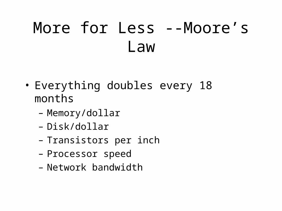
• Everything doubles every 18 months– Memory/dollar– Disk/dollar– Transistors per inch– Processor speed– Network bandwidth

Practical Details
• Problem sets 20%
• Lab reports 10%
• Midterm exam 25%
• Final exam 25%
• Class Participation 20%

Building a computer

Layers of Abstraction• Build more and more powerful tools out
of simpler ones.
ReallySimpleStuff
Computers

A Simple Logic Puzzle• Frank will go to the party if
Ed goes AND Dan does NOT.
• Dan will go if Bob does NOT go OR if Carole goes.
• Ed will go to the party if Alice AND Bob go.
• Alice and Bob decide to go,but Carol stays home.
• Will Frank go to the party?

Using 0’s and 1’s• What do 0’s and 1’s mean?
• For now, we’ll take “Natural meanings:”
• For example, if we have a variable Alice forwhether Alice goes to the party,
• If Alice goes, we write Alice = 1
• If Alice doesn’t, we write Alice = 0
0 = False 1 = True

Logic Gates • Computers are circuits made of Logic
Gates.
• Logic gates manipulate 0’s and 1’s (False and True) by letting electrons flow or not.
• We’ll look at three types of Logic Gates:
• AND are all inputs true?
• OR is one input true?
• NOT flip the truth value

AND Gate
ANDW
Y
ZX W X Y Z
0 0 0 0
0 0 1 0
0 1 0 0
0 1 1 0
1 0 0 0
1 0 1 0
1 1 0 0
1 1 1 1

OR Gate
W X Y Z
0 0 0 0
0 0 1 1
0 1 0 1
0 1 1 1
1 0 0 1
1 0 1 1
1 1 0 1
1 1 1 1
ORW
Y
ZX
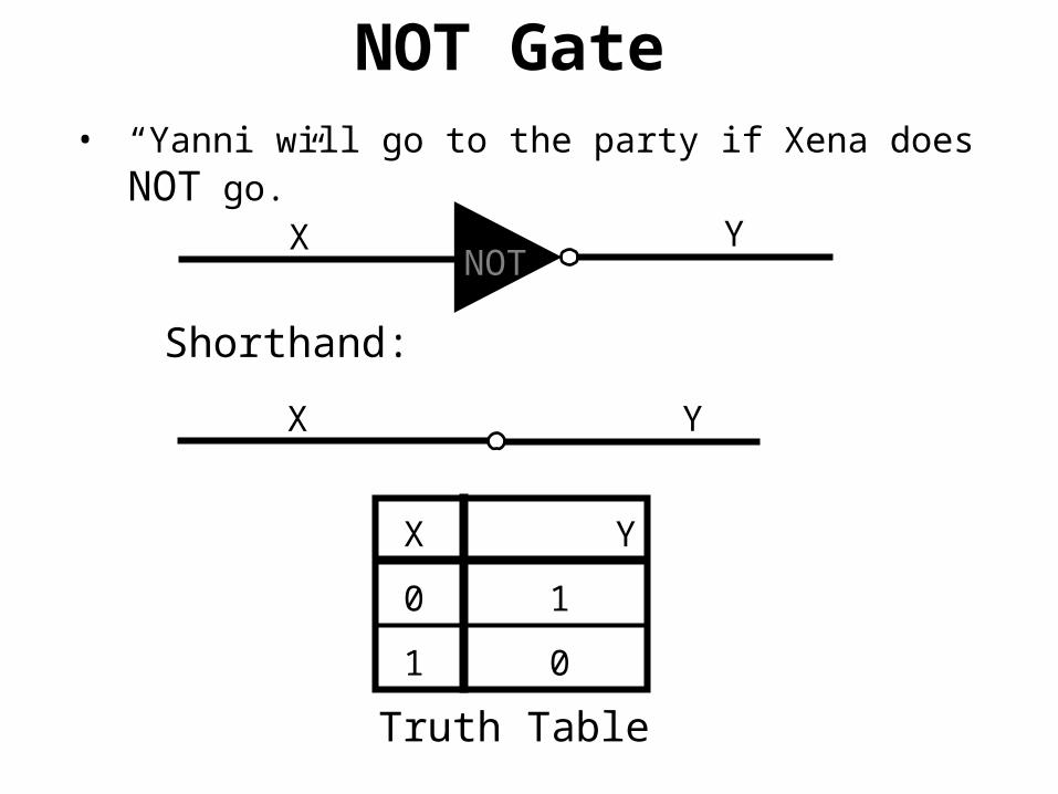
NOT Gate • “Yanni will go to the party if Xena does NOT
go.”X Y
Truth Table
NOT
X Y
Shorthand:
X Y
0 1
1 0

OR
AND
Logic Puzzle Circuit
AND
Ed
Dan
Frank
Dan will go if Bob does NOT go OR if Carole goes.
Carole
Alice
Bob

Given Any Truth Table
A B C F
0 0 0 0
0 0 1 1
0 1 0 1
0 1 1 0
1 0 0 0
1 0 1 0
1 1 0 1
1 1 1 0

Given Any Truth Table
ANDA
C
B
ANDA
C
ANDA
C
B
B
A B C F
0 0 0 0
0 0 1 1
0 1 0 1
0 1 1 0
1 0 0 0
1 0 1 0
1 1 0 1
1 1 1 0
Build AND gate for each output 1

OR
Given Any Truth Table
ANDA
C
B
ANDA
C
ANDA
C
B
B
Finally, combine ANDswith an OR gate.
F
Can build logic for any Truth table this way

Universality• Note same idea works no matter how
manyinput variables. So for ANY Truth Table we can write down,we can make a circuit for it using only 3 Logic Gates: AND, OR, NOT
• This gives us a very powerful tool !
• But, in practice, we are limited in size we can realize – numeracy exercise.

Our First Abstract ToolUniversal Method: Circuits for ANY Truth Table
Computers
We are here
UniversalMethod
0’s&1’s

Powers of 2 (cont.)• Some rough numbers:
210 1,000 (103 ) kilo
220 1,000,000 (106 ) mega
RAM
230 109 giga
disk
240 1012 tera BIG
disk
250 1015 peta
260 1018 exa
knowledge

Representing Information• We represent information with 0’s and 1’s
• Numbers
• Use binary or hexadecimal
• Letters
• Use ASCII
• Sounds
• Use samples
• Images
• Use pixels

Adding Binary Numbers
X Y sum
0 0 0
0 1 1
1 0 1
1 1 0
ORsum
ANDX
Y
ANDX
Y
carryAND
X
Y
X Y carry
0 0 0
0 1 0
1 0 0
1 1 1

Addition
We can use 1 building block to add numbers of any length.
Black box operation
ith bit of X
ith bit of Y
carry bit
ith bit of Z
carry bit out
Abstraction in action -- This is a piece of a carry-ripple adder

Carry-Ripple Adder
Z0
C0
UniversalCircuit
X0
Y0
Z1
C1
UniversalCircuitFor Z2 and carry
X1
Y1
Z2
C2
UniversalCircuitFor Z2 and carry
X2
Y2
X2 X1 X0 Y2 Y1 Y0============C2 Z2 Z1 Z0
0
Fixed at 0

Memory

Enter Rita• Matt doesn’t like Rita
• Matt decides to go to the party if Sue decides to go OR:
• If he (Matt) already feels like going AND Rita decides NOT to go.
OR
AND
Sue
Rita
Matt
Feedback Wire

The Flip-Flop
OR
AND
Set
Reset
M
• M becomes 1 if Set is turned on
• M becomes 0 if Reset is turned on
• Otherwise (if Set and Reset are both 0), M just remembers its value

The Flip-Flop
• M becomes 1 if Set is turned on
• M becomes 0 if Reset is turned on
• Otherwise (if Set and Reset are both 0), M just remembers its value
S
R
M

The Data Flip-Flop
• If Write = 0, M just keeps its value.(It ignores D.)
• If Write = 1, then M becomes set to D
D
Write
M

RAM• Group 8 of them together.
• 8 bits (b)is called abyte (B).
• Most RAMis arrangedin bytes.
DM
W
DM
W
DM
W
DM
W
DM
W
DM
W
DM
W
DM
W

RAM (cont.)• We want a HUGE number of such 1 byte
memory cells.
• Problem: How do we indicate which byte ofmemory we want to use at any given time?
1B
1B
1B
1B
1B
1B
1B
1B
1B
1B
1B
1B
1B
1B
1B
1B
1B
1B
1B
1B
1B
1B
1B
1B
1B
1B
1B
1B
1B
1B
1B
1B

RAM (cont.)
220
bytes of RAM
(1 Mega-byte)Write
Address
Data input Data Output
20 bits of address
8 bits (1 byte)of data

ReviewOn our way to building a computer…
Computers
We are here
LogicCircuits:UniversalMethod
0’s&1’s
RepresentInfo with0’s & 1’s(aka bits)
MemoryCircuits

The System Clock
• “500 Mhz Pentium III computer…”
• What does “500 Mhz” mean?
• It refers to the speed of the System Clock. (actually this is only one of the clocks…)
• All digital systems have such “Clocks,” even traffic lights and elevator control systems.

Our System:A Traffic Light

A Traffic Light
• Intersection of two one-way roads
CarSensors
B
A

Light
ATraffic Light Behavior
IF A=1
AND B=0
Always
IF A=0
AND B=1
Otherwise
Light BOtherwise
Always
Note:Clock beatsevery 4 sec.So Light is Yellow for
4 sec.

Light
ATraffic Light State Machine
IF A=1
AND B=0
Always
IF A=0
AND B=1
Otherwise
Light BOtherwise
Always
Note:Clock beatsevery 4 sec.So Light is Yellow for
4 sec.

Light
ATraffic Light States
IF A=1
AND B=0
Always
IF A=0
AND B=1
Otherwise
Light BOtherwise
Always
00 01
1011

Traffic Light BehaviorBuild A Truth Table
for next state / Output
M1 M2 A B D1 D2 Light A Red Light B Red …
0 0 1 0 0 1 1 0
0 1 * * 1 0 1 0
1 0 0 1 1 1 0 1
1 1 * * 0 0 0 1
0 0 0 0 0 0 1 0
… … … … … … …

Traffic Light Design
2-bitMemoryRegisterClock
Sensor A
Sensor B
Logic For
Next State
&Output 6 Outputs:
for eachLight
Current State

Design for Any State Machine
MemoryRegisterClock
Inputs
Logic For
Next State
&Output Outputs
Current State
Manybits

State Machinesin Real Life
• Elevator control systems
• Car control systems
• VCR’s
• Alarm Clocks
• Personal Computers
• … Just about everything!

Computers

Computer Architecture
Bus
CPU
RAM
Keyboard
HardDisk
Display
CD-ROM

The Bus
Bus
• Communication on the bus is via postcards
• CPU puts “Keyboard, did the user type anything?” (represented in some way) on the Bus.
CPU Keyboard Display
“Keyboard, did the user type anything?”
The Bus
Bus
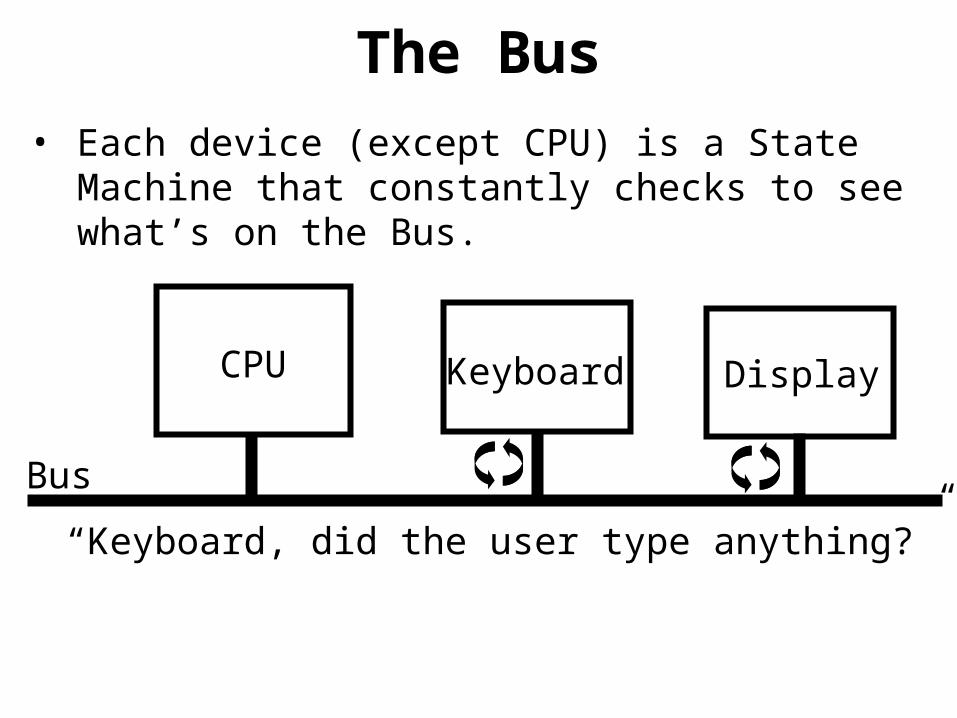
• Each device (except CPU) is a State Machine that constantly checks to see what’s on the Bus.
CPU Keyboard Display
“Keyboard, did the user type anything?”

The Bus
Bus
• Keyboard notices that its name is on the Bus,and reads info. Other devices ignore the info.
CPU Keyboard Display
“Keyboard, did the user type anything?”

The Bus
Bus
• Keyboard then writes “CPU: Yes, user typed ‘a’.” to the Bus.
CPU Keyboard Display
“CPU: Yes, user typed ‘a’.”

The Bus
Bus
• At some point, CPU reads the Bus, and getsthe Keyboard’s response.
CPU Keyboard Display
“CPU: Yes, user typed ‘a’.”

The CPU (cont.)Memory Registers
Register 0
Register 1
Register 2
Register 3
Instruction Register
Instr. Pointer (IP)
Arithmetic/ LogicUnit
Control Unit(State Machine)

Important Point• One of the important features of the von
Neumann model is the fact that:
• The instructions themselves
And
• The data the instructions manipulate
are all stored in the same RAM.
• This was one of the revolutionary features of the modern computer, totally unlike Punch-Card computers proposed in the past.

Important Point• This innovation is crucial to modern
computing.
• It even allows for the possibility of programs that change themselves as they are executed.
• With great power comes great risk…
• Computer Viruses!
Machine Language
• We now have a machine that can execute instructions.
• Basic Questions:
• What instructions?
• How do computers understand these instructions? (Representation)
• What does software look like to acomputer?

Instructions
• 16 possible Op-Codes:0: halt1: add2: subtract3: multiply4: bus output5: jump6: jump if positive7: jump & count8: bus input9: loadA: storeB: load direct/addr.C: NANDD: ANDE: Shift RightF: Shift Left

Adding Numbers• Simple Program to calculate
1 + 2 + 3 + 4 + 5 + 6 = 21 = 15 (hex)10: Load R0 0001 (always 1)11: Load R2 0000 (running total)12: Load R1 0001 (current number)
13: Add R2 R2 + R1 (R2=1)14: Add R1 R1 + R0 (R1=2)
15: Add R2 R2 + R1 (R2=3)16: Add R1 R1 + R0 (R1=3)
17: Add R2 R2 + R1 (R2=6)18: Add R1 R1 + R0 (R1=4)
19: Add R2 R2 + R1 (R2=A)1A: Add R1 R1 + R0 (R1=5)
1B: Add R2 R2 + R1 (R2=F)1C: Add R1 R1 + R0 (R1=6)
1D: Add R2 R2 + R1 (R2=15)1E: halt

Adding Numbers• Alternate Loop using Jump & Count for
1 + 2 + 3 + 4 + 5 + … + N10: Load R1 0006 (N)11: Load R2 0000 (running total)
12: Add R2 R2 + R1 (add in N)
13: Jump to 12 and (If N isn’t 0 yet, decrease R1 if (R1>0) Let N=N-1, and go back)
14: halt (N is now 0, and R2 = 1+2+…+N)

Sound is a waveform

Sampling the waveform

The approximation

Even finer sampling

Digital vs. Analog
• A sound file is just a sequence of bytes– On a CD, the sampling rate is 44,100 samples per second.
Each sample is quantized into a number in the range from 0 to 65,535, So a CD has 44,100 numbers (each 2 bytes) per channel per second of music.
• A graphic image is just a sequence of bytes– An image is made up of pixels– Each pixel might be represented by 3 bytes giving color
intensities.
• Manipulating sounds or images just involves manipulating numbers

Numeracy
• CD has 44,100 2 byte samples per second. • 44,100 x 2 x 60 x 2 (channels) = 10.09
megabytes per CD minute• A CD is 74 minutes (746 megabytes) long. • MP3 players typically use memory 32 or 64
megabytes in size. (or 3-6 minutes)
• Compression is needed

The need for compression
• A CD is 746 megabytes long
• A printed page requires 86.4 Megabytes of storage

Simple compression
• Simple compression – Use redundancy
• More complex compression– Lossy vs. lossless– Ideas for lossy
• Drop frequencies you can’t hear
• Drop small differences you won’t notice

More complex compression
• Lossy compression– Can save space by eliminating parts of the
image/sound that don’t matter very much– Big savings compared to lossless, but the signal
cannot be fully recovered.– Ideas
• Dropping frequencies you can’t hear• Dropping small differences you won’t notice
– Generally large savings compared to lossless

Pause for experiment