middle rio grande conservancy district (mrgcd) … advantages and disadvantages of each gate type...
TRANSCRIPT

PAP 792
II Middle Rio Grande Conservancy District (MRGCD) Design and
Estimates for Sandia Lakes Wasteway Overshot Gate
by
Clifford A. Pugh
U.S. Bureau of Reclamation
July 31, 1998
WATER RESOURCES RESEARCH LABORATORY OFFICIAL FILE COPY


United States Department of the Interior BUREAU OF RECLAMATION
Reclamation Service Center P.O. Box 25007
Building 67, Denver Federal Center Denver, Colorado 80225-0007
IN REPLY REFER TO:
D-8560 RES-3.50
►~1 ►~ i ; I DiiliyI
To: Chris Gorbach, ALB-709
From: Cliff Pugh, D-8560
Subject: Middle Rio Grande Conservancy District (MRGCD) Design and Estimates for Sandia Lakes Wasteway Overshot Gate
The attached report considers three types of overshot gates for the upstream water level control and flow measurement at the Sandia Lakes Wasteway. The advantages and disadvantages of each gate type are discussed.
I would be glad to discuss any questions that you have or talk to the MRGCD about the options.
Attachment
cc: D-8560 (Burgi, Einhellig, K. Frizell, Higgs, Rogers), D-8560 (PAP file) (w/att to each)

r
P F
Y ~
i
- -
- ' j. ; .- •1n ` r .Yp -ice '"- a Ri ~.'. _ - ~-
.

Sandia Lakes Wasteway Structure MEASUREMENT AND AUTOMATION NEEDS
by
Clifford A. Pugh Water Resources Research Laboratory
Denver, Colorado
S pEPARTMENT OF THE INTF9i
BUREAU OF RECLAMA~~~N I
July 1998

Background
The Middle Rio Grande Conservancy District (MRGCD) was established in 1925 to provide drainage, flood control, and irrigation to the inner valley of the Rio Grande, extending approximately 140 miles from Cochiti Dam to the Bosque del Apache National Wildlife Refuge. The areas served by the district includes parts of metropolitan Albuquerque, Los Lunas, Belen, Socorro, six Indian pueblos, extensive agricultural lands, rural residential areas, and five game and fish refuges. As widely varying demands for water increase, it is becoming critical for the district to improve water management practices. To accomplish this, the district must be able to obtain more accurate and timely information on the amounts of water being diverted, conveyed, delivered, and returned to the river.
Reclamation is responsible under the Middle Rio Grande Project and other project authorizations for promoting efficient delivery of water through the middle Rio Grande valley to ensure delivery of Rio Grande water to Mexico and to assist the State of New Mexico in meeting its Rio Grande Compact obligations. In this role, Reclamation's Albuquerque Area Office (AAO) has worked with the State and the district to outline a Water Management Study Plan and has requested technical assistance from the Water Resources Research Laboratory (WRRL) to provide an overview of possible water management improvements. In 1996, the following initial assessment was made for the Sandia Lakes Wasteway by WRRL personnel.
Sandia Lakes Wasteway No existing measurement. Two slide Difficult site for measurement. The Sandia Pueblo gates from canal into natural channel gates are in poor condition; no power,
that curves to return to river. minimal head available between canal and river channel. Possible backwater.
Upon further review and discussion with Chris Gorbach from the AAO some type of overshot gate in the wasteway still appears to be the best solution. An overshot gate is the best device for controlling the upstream water level. Changes in flow only cause a slight variation in the upstream water level, where a larger water surface elevation change would result from an undershot slide or radial gate. Also, tailwater will not affect the overshot gate if the tailwater level is below the gate lip. Tailwater submerges the outflow from a slide or radial gate. Overshot gates are also very good for passing floating debris.
The overshot gate elevation was raised 4 ft above the existing sill. This modification should reduce the cost of the gate considerably and reduce the size of the operator needed. The raised overshot gate will provide about 200 ft3/sec of flow capacity at water surface elevation 5017 and 400 ft3/sec at elevation 5019. Tailwater should be less of a factor with a raised sill and sediment deposition should not be as much of a problem around the gate. Therefore, the estimates were made with a raised sill assumption, and an estimate for installing a 4-ft-high sill with a drain gate was included for each option.
Figures 1 and 2 show the plan and section through Sandia Lakes wasteway. Figures 3, 4, and 5 are layouts for each type of gate.

The three different types of overshot gates listed below were considered for this project.
• Cable and hoist lifted gate (Hydrogate) • Pneumatic with air driven rubber bladder beneath the steel gate leaf (Obermeyer) • Chain driven with two scissors-type hinged gate leaves (Langeman)
Flow measurement would be accomplished by measuring the position of the gate and the upstream water level. A local microprocessor will compute flows from these measurements. The general layout of the Sandia Lakes Wasteway is shown below. The structure controls the upstream water level to turn out flow from the Atrisco Feeder Canal to the Albuquerque Main Canal. Flow passing over the Sandia Lakes Wasteway returns to the Rio Grande River and needs to be measured to assist in water accounting for the District.
Figure 1 - Location of Sandia Lakes Wasteway.
To ALBUQUERQUE MAIN CANAL
3 O
:7

SANDIA LAKES WASTEWAY
A
I'
A
PLAN VIEW
SECTION A-A
Figure 2 - Sandia Lakes Wasteway.

r- 20"-0' Y9'-O' 20-0' --~i
A -- A
SANDIA LAKES WASTEWAY
HYDRO GATE
PLAN VIEW
A
SECTION A-A
Figure 3 - Hydrogate installation.
4

ice- 10'-0" 19'-0" ?0'-0' -.
A -- A
SANDIA LAKES WASTEWAY
LANGEMANN GATE
PLAN VIEW
A
SECTION A-A
Figure 4 - Langeman Gate Installation.

SANDIA LAKES WASTE-WAY
OBERMEYER GATE
NOTE.- 14'—J" Concrete Rood Deck not drown in Pion ViZ
Coniro/ Bo. Confoinhv tii C.,N--r. T-h. —d C—f l EWipnenf
A A
70'-0" 19'-O" 20'-0'
PLAN VIEW
SECTION A—A
Figure 5 - Obermeyer Gate Installation.
0

Cost estimate for the three options of overshot gate.
Item Supplier Quantity Est. Cost
Concrete sill 3 to 4 ft high with drain and slide gate to Local 10 yd $3000 dewater upstream and to help sluice sediment. plus gate
Overshot gate 12 ft wide. Control over 3 ft of Obermeyer, 1 $18,000 water surface. Langeman, or $15,800
Hydrogate $23,527
Estimated extra work required to install gate. Obermeyer, 2 SD $1000 Langeman, or 2 SD $1000
Hydrogate 5 SD $2500
Sub-total main gate installation - without programable upstream water level control and flow monitoring
Obermeyer, Langeman, or
Hydrogate
$22,000 $19,800 $29,027
Additional Equipment needed for upstream water level control and flow monitoring and telemetry.
RTU with radio and modem 1 $2000
Software 1 $700
Mounting RTU in enclosure with wiring and antennas (includes Nema 4 enclosure)
1 $1100
Bubbler (water level sensor) Digital Control Corp.
1 $800
Control interface (relays and switches) Grainger 2 $600
Solar panel and voltage regulator Photocom 1 $900
Deep cycle battery (auto parts store)
1 $100
Miscellaneous arts* 1800
Total Cost - Parts $8000

Additional Labor needed for installation of controllers.
Item Quantity Cost
Software development 2 days labor $1200
Installation time 3 days labor $1800
Travel and per them $600
Total cost - labor $3600
Grand total - parts and labor Obermeyer $33,600 Langeman S31,400
__j Hydrofrat $40,627
These estimates were done with comparable items included in each of the three options. Actual costs may vary somewhat from the estimate.
Each of the options has certain advantages.
• If the upstream controller option by Langeman is chosen, the entire installation and training would be turn-key, done by Aqua Systems (see the attached estimate.) Aqua Systems would deliver the unit as a package and provide training and commissioning. Local labor could be used for installation of the gate and control box, which should be very straight forward.
• The Obermeyer installation is only slightly more complicated than the Langeman. It requires only a compressor, air tank, relays, solar panel, battery, and valves to operate. There are no cables or chains required to pass through to the platform above. Long-term maintenance may be less.
• The Hydrogate could be installed with a manual lift without a motor driven actuator. The hand-operated version would eliminate the power requirement and would save $5000 over the version with an electric actuator. Power and a motor operator could be added later if needed. The installation of the Hydrogate is more involved than the Obermeyer or Langeman. The installation drawings are provided by Hydrogate.
• The controller and solar equipment would be purchased and installed by the WRRL for the Obermeyer or Hydrogate options. Therefore, technical assistance could be provided for any problems in the future. Compatibility of the Aqua Systems controller with planned telemetry and control systems in the MRGCD for future integration with the overall system would need to be investigated.
The attachments give additional information and pictures of each type of gate.

w "
..w~•~►~ +•_ •w~.r -Mww ~.v a~ha~wF:+. .+5•adb s+~+a+uw.w- •~ Y! M^ ~FFim '~*+~R+$~Ar MY1~
r.
~__-__ _..._-."w^."r. _n. .•:gib .n~:W.iFMM`.ww~rF .n+tis4n ~- Lei' .aW -vlw., -a-~.e. .,► ....- .
-'
~y .~_ ff_s.W. ATv.Is~-T ~~.
.. -~... --":t.+.-.-,~, .ar, •+s- e.syt•
-a" ~~ - - _.••.+w r ++.r, :~-.~ _.e Ia. :s~r"t .,. y,.0 /Sa>,nnyH, -s. -- ._ -
-. -~' ~ ._ .r►w _. w~c~e.,n-«:-~:s-"....w...,--"- -'~.- a „~~wa...ve.••. ,,ei~e. •.~r,~:.~:~.~es• ..-.,/..s+iM+ . rr~+ ,yr-... - ••-- •~ .:--", - -.' - - -
~y—
s
. __ _._ -., _._ .,...._ y . ~.-..~C ~~~_ •..'•''~'._~ -e~aen.' - ~`~~`~.~s~::~it~.'. ~.~._- tis=,. ~imv ~.-~.:.~+:sFr-~f-'~wc «.r-~.-~ _ __ __—
-------------
,fit. 4 r -- .___
- _..
q~+1-3'•--~'~3' 1 ~«%e ~~-E_~ ~~-_~.~a}.~"`->-. ~,5:-7f~~:~a ,̂~3,i - _~ ~.~. -~-.g ~t~-iSf"~~~.9 .~~i ~,T_..~~E~a~_.
.~„
- _ L3f~t`' a 1 ~+~' i~; r : # ':~i~,~'-~+# H',:'a3~d:-.~~~i ~~~; h ~:?~ }, ~a .t j.~.~ ~, _`-- -
y ~ ~ ~.- ~ ~; ~~.-. ~ ~ _
x•
- __.."'~s
f&
~_s- ._..~-`.~~~ t t s~r. #t .i~i}a 2^?t:{~~ t .•~t.Y ~~ µ„~~.;~'.~-: 'y~ri'.`#t ~_'~'-~1 t~J!~`.2 '*43f-".` ~/.>~'~~~.r~+a..a-.1~ S._.._ ~-_, _. __ „
-- - - - - : ~nrt`. -x~.-y:.~.~.r$-.~3 .y3~.'•i..-x4 -ii: 1 .--_-~ to-- IT
. . .,~,: , 'fie"_ * -*" 4 ;~ rte-:^r •.~ ='_a~ .. r .Jr~:r _~ --~:v_-L l__ _-- _
... _ _. _. ._ `~-..; •.̀2+V _ r f.'+~"~~} N .~-. S ~..~skt ~,G 4-1"df. T' -.. a. u,- S -
'c'JS C~, > .., l< TIS " at
v_ .,; ~ i~ _. _- • T= _ - ~ - .'f~~ 7t ty 'r x ..~«r':-,----'", «~ !+=_ _ i 1~:`..t3 jY ~ ~ y~̀ t".̀ J . J ~ --. _ ,. ~. _
- ~ -_ -._.F{~.~' };f lx ;Ar ~-.
TT
. - ,•L 9 .24 t',-^ ~•~'~~-_,- S '~,~i. A _ mil ~ .1., a . -t3 _. - -.._- _
Cit... J~4.`..

OVERSHOT GATE
Options / Features: - Manual lift: An Inexpensive way to begin the use of Overshot Gates. Eliminates the use of check boards. Power is not needed at the site and allows full control of the gate by traditional hand crank operation. Portable electric, or gas powered operators are available for easier gate operation.
- Solar power : Used In remote locations where line power is not available or expensive to obtain. A DC motor is used In conjunction with solar panels and batteries. This option can be upgraded to a automated site.
- AC power: AC power options are available with use of several brands of AC actuators as well DC motors. Automation is also an option with AC power.
- Automation is available with either power option. The automation package can be In the way of gate position, upstream level, down stream level, or flow control. Automation can be installed when the gate is or at a later date.
- Hoists: The lifts used on Overshot gates can be made in many different styles from tandem lifts to single gear boxes. The lifts can be made with cable drums or without drums. Unique applications of hoist are often required and available due to existing structures on or near canals.
Sizing: Overshot Gates can be built in most sizes to accommodate your canal and needs. The gates are built to the customer's specifications some of which may not be listed here, please ask about special applications.

m ,T.a.wC TS
_ 1
40,
ai s ~ i
-- "~ ~jt . a.`R.a • .0 .+ ale. y .• -~ - -- -
—... _ _ __. _ 's—c._~ n _: ~,
i ~''{t r'"a '''iffi,^~,r̂~.E., a _'•5,` 3Yii 3'I"'. i-!_- rf -_.*^- 1 --"• _ - _ _ - -
c J E J
oi -~ _- 4ii~.Y_F .~ p'.k~. * -
.~'iY ~
• ~-'3~1F~ ~ by ~~~~~.f~
_ _ T -1~ •< 't-, Vii.. f
IJ
a .a
a ~
s ~r t - rS1f~ ^LJ;;
a< rz> ` c.f 9J '. ; L i►``f. )~c~:;« ~7 1^ •s !
- .
d ..
f 1
~ r
;• r ,,....rt, a..:_ ,,.7.~":""-̀ •.. ... .. ........ ._ ..... .._'ter'" • 1, _ -
f`

LANG EMANN° Gate and Controller Automatic Flow or Level Control
Invented by Peter Langemann, the Langemann® Gate and controller provides solutions to a host of water control problems. This system was developed through a cooperative effort between the. St. Mary River Irrigation District, Peter Langemann and Aqua Systems 2000 Inc (AS2I).
The patented design has gained recognition and acceptance due to its simplicity, overshot technology, control capabilities and low power requirements.
The Langemann® Gate is comprised of double-hinged gate leaves, a rigid frame with side plates and a drive mechanism capable of operation using a battery and solar panel. In retrofit applications each gate is engineered and built to fit an existing structure. The leaves of the Langemann® Gate extend upstream from the existing stoplog guides which means that often little or no site preparation is required.
The Langemann® Gate functions as a vertically adjustable weir. It has a unique water level sensing and control system that provides functions of either flow control or level control for the installation. For operation in upstream level control the Langemann® gate functions well in either manual or automated mode. It is also readily adapted to other control and communications systems.
You are only a phone call away from exploring the use of a Langemann® Gate for some of your more difficult water control problems.
1606 Lakeside Road Lethbridge, Alberta T1 K 3G8
Tel- (403) 380-2724 Fax- (403) 327-8543 E- mail: [email protected]
1-800-315-8947
CONTENTS
Automatic Flow or Level Control ..................... 1
Advantages & Operation Modes ..................... 2
Ease of Installation . ............................... 3
Commissioning and Operating the Langemann® Gate ... 4
Visit our site at
http://u panet. uleth-ca/-aqua_2000
"Innovative Water Control Products"
Patent Numbers: Canada - 2096269, USA - 5372456, Australia - 662872, Mexico - 937289, Other Patents Pending

Advantages & Operation Modes
Application Suitability A Langemann0 Gate and controller can either:
✓ Maintain a constant upstream water level (such as in a check structure) or
✓ Provide a pre-determined constant flow to downstream users (such as in a turnout).
Practical applications include irrigation check structures, turnouts, spillways, and diversion structures. The LangemannO Gate can also be used as a variable weir in water and sewage treatment plants as well as flood control structures in urban environments.
General Advantages Control System: Low cost, reliable electronic
technology is used for stand-alone automatic control.
Low Power Requirements: The unique distribution of water pressures afforded by the gate configuration and the use of low friction operating components provides for remarkably low power requirements. This results in cost savings in the operating mechanism and power supply. The automation package has extremely low power requirements, drawing only 15 milliamperes from a 12 volt supply. Battery and solar power technology can be used on relatively large gates, eliminating the need for costly electrical installations.
Precise Positioning: The LangemannO Gate provides positive linear movement in either direction in increments as small as 3 mm (1/8
inch). Convenient staff gauge placement and the linear relationship of drive train, gate and water level provides reliable operating information.
Ease of Installation: The Langemann0 Gate is designed to fit into the stoplog guides of an existing structure which greatly reduces the amount of installation time required. This allows major gates to be installed in a couple of hours. It is possible to install the gate with the canal "in the wet' thus eliminating the need to shut down the operation of the canal.
Level Control Mode Intuitive Control: Upstream water level changes
are achieved with the Langemann0 Gate by adjusting the gate crest in the same amount and direction of the change in level desired. Even under manual control, performance is far superior to undershot style gates. With automation, precise water level control is achieved even with widely ranging canal flows.
Inherent Safety: As an overshot gate, the LangemannO Gate allows surge flows and debris to pass over its crest and continue flowing downstream. This avoids the disadvantages of undershot gates which tend to trap debris and surge flows.
Flow Control Mode Control and Measurement: The Langemann0
Gate provides both flow control and measurement by tracking the water level changes and adjusting the gate accordingly. The unique feature of level sensor and gate operated by the same device eliminates any potential for hysteresis interfering with the accuracy of the settings.
Low Head Loss: Head loss requirements are much less than other control and measurement combinations. Except in extreme conditions, accuracy is not affected by fluctuations in tail water levels.
User Friendly Setpoint Changes: Flow settings are accomplished by a simple and direct switch operation on the front panel of the control cabinet. Either a specific flow setting or an incremental flow change is readily achieved.

Ease of Installation The LangemannO gate is custom-designed and can be manufactured in a variety of sizes capable of handling a wide range of check structure sizes and canal flows.
The gate ships fully assembled and ready for installation and can be installed with water in the canal. A relatively low flow, however, simplifies the installation.
The installation of the gate is accomplished in a matter of hours due to the simplicity of design which makes full use of the existing infrastructure. Since the gate leaves extend upstream, the amount of preparatory work at the site is kept to a minimum allowing the existing operating platform to be reused.
The installation begins with the removal of the previously used gate and any other obstructions. Using a light-duty crane the new gate is lowered into position. Correct positioning and seating of sealing surfaces minimizes leakages.
Once the gate frame has been seated, installing the battery and level sensor, checking settings of limit switches and overload switch and establishing the set point completes the installation.
The LangemannO gate can also be used in manual operation mode for upstream level control, and gate movements can be done by hand or a modified electric drill motor.
All the instrumentation and sensors used are battery-powered. A deep discharge battery is maintained fully charged by means of a solar panel.
After these steps have been completed, the installation is finished, the canal can be placed in service and the gate will operate to maintain the desired level or flow.
Features and Options
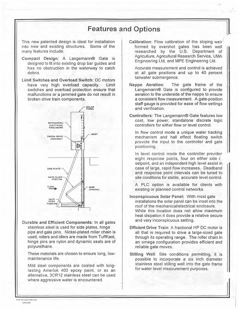
This new patented design is ideal for installation into new and existing structures. Some of the many features include:
Compact Design: A Langemann(D Gate is designed to fit into existing drop bar guides and has no obstruction in the waterway to catch debris.
Limit Switches and Overload Switch: DC motors have very high overload capacity. Limit switches and overload protection ensure that malfunctions or a jammed gate do not result in broken drive train components.
SOLAR PANEL
MECHANICAL/ 1 ELECTRICAL I ENCLOSURE
I
MAST OMEGA DRIVE
A66EMBLY
SIDE PLATE
GATE CLOSE POS ITON
FLOW` Y/ II CHANNEL
GATE OPEN
Durable and Efficient Components: In all gates stainless steel is used for side plates, hinge pipe and gate pins. Nickel-plated roller chain is used, rollers and idlers are made from TuffKast, hinge pins are nylon and dynamic seals are of polyurethane.
These materials are chosen to ensure long, low-maintenance life.
Mild steel components are coated with long-lasting Amerlok 400 epoxy paint, or as an alternative, 3CR12 stainless steel can be used where aggressive water is encountered.
Calibration: Flow calibration of the sloping weir' formed by overshot gates has been well researched by the U.S. Department of Agriculture, Agricultural Research Service, UMA Engineering Ltd. and MPE Engineering Ltd.
Accurate measurement and control is achieved at all gate positions and up to 40 percent tailwater submergence.
Nappe Aeration: The gate frame of the Langemann® Gate is configured to provide aeration to the underside of the nappe to ensure a consistent flow measurement. A gate-position staff gauge is provided for ease of flow settings and verification.
Controllers: The Langemann® Gate features low cost, low power, standalone * discrete logic controllers for either flow or level control.
In flow control mode a unique water tracking mechanism and hall effect floating switch provide the input to the controller and gate positioning.
In level control mode the controller provideF eight response points, four on either side c setpoint, and an independent high level assist in case of large, rapid flow increases. Deadband and response point intervals can be tuned to site conditions for stable, accurate level control.
A PLC option is available for clients with existing or planned control networks.
Inconspicuous Solar Panel: With most gate installations the solar panel can be inset into the roof of the mechanical/electrical enclosure. While this location does not allow maximum heat disipation it does provide a relative secure and very inconspicuous setting.
Efficient Drive Train: A fractional HP DC motor is all that is required to drive a large-sized gate through its operating range. The roller chain in an omega configuration provides efficient and reliable gate moves.
Stilling Well: Site conditions permitting, it is possible to incorporate a six inch diameter stainless steel stilling well into the gate frame for water level measurement purposes.
CANADA

U. - =M-U-11 To: ;;4119W Pugh Dow 9815M9 Time: 10:01:14 Page 3 of 4
1606 Lakeside Road, Lethbridge, Alberta, Canada T1 K 3G3 Tel: (403) 380- 2724 Fax: (403) 327-8543 F-000-315-6947
BUDGET
To: U. S. Bureau of Reclamation F.O. 25007, D-8560 Denver, CO 80225
Attention: Mr. Cliff Pugh Currency: us Freight: 8400
F.O.B. Denver, CO Reference: Telephone request. Delivery:
Duties: Included We are pleased to provide a budget on the supply of the following items: Taxes: Not included
REM I QUANTITY DESCRIPTION UNIT PRICE TOTAL
1 1 Langemann Gate - manual DC electric operation. $ 15,000.00 S 15,000.00 - 12 feet wide X 4.0 feet high, 3.0 feet of opening. - mild steel with Amerlock 400 epoxy coating. - stainless steel side plates.
°- side seals gate to side plate. - staff gauge gate position. - drive train -
vertical rising masts with omega configuration. # 40 roller chain. Winsinith - 920 MDSFO - 2000:1 speed reducer Pacific Scientific - 118 HP 12 VDC motor.
- 10 watt solar panel and regulator. - electrical includes a NEMA 12 electrical panel, ammeter,
limit switch, overload breaker, terminal and fuse blocks. 5 inches per minute gate movement.
2 1 upstream water level controller: $ 8,000.00 $ 8,000.00 - Programmable controller. - Unimeasure water level measuring device. - Upgrade to 50 watt solar panel - Ustream water level control and flow monitoring software. - Operation and maintenance manual.
3 1 Commissioning and training: $ 3,500.00 $ 3,500.00
4 1 Shipping S 800.00 $ 800.00
Total of budget = S 27,300.00
Innovative Water Control Products
Page 1 of 1 Date- 98/05/19

.lerald D. Robinson To: Clifford Pugh Date: 8815118 Time: 10:01:51 Page 4 of 4
Aient: Design
U.S.B.R. -Denver, CO 4.2 ems 150 cfs
Project:
Gate Width: 3.7 metres 12 feet
Factored Head Factored Head Submergence Ratios - SR Submergence Ratios - SR
Head - metres 0.50
1
0.60 0.70 Oleo Head - feet 0.50 0.60 0.70 0.80 Flow Langemann Submergence Factors - Cdf Flow Langemann Submergence Factors - Cdf
cros 3 Gate J21 SR <40 0.92 0.88 0.82 0.72 cfs(3)- _ Gate Z SR <40 0.92 0.68 0.82 0.72
0.00 0.00 0 ..... .....----. ..._.._..................... I... ............................_ ..__...._......................... 0.00 0.06 0.04 0.04 0.04 _ .............................................................................................- 0.05 0.05 2 . ............. 0.13 ....................I......_....._........
0.14 .................................................................... 0.14 0.15 O.tfi
0.12 0.06 0.07 0.07 0.07 0.06 4 ................ 0.21 .......................................... 0.22 0.23 ............I....................._........................ 0.24 0.28 .... .......
0.16 0.08 0.09 0.09 ..............................._ 0.10 .......... .......... 0.10 B .... I..................... 0.28
..................................... _. . ............... 0.29 ....................... 0.30 0.32 . ...... _ ........... 0. ........ 0.24 0.10 0.11 0.11 0.12 0.13 _.__......_ 8 ......................... 0.33 ..........._........._..._.............. 0-35 ........._..............._ 0.36 ............._........._ 0.38 0.42 ... .... 0.3 0.12 0.1 Z 0.13 0... 0.15 11 0.39 0.41 0.42 0.44 0.48 0...... 0..13 ................
_.._.........._ .. ....... ......0
.14.... -
0.1.5..
.................... -0.1.............
0.17 .................._............................... 13 0.44 ............................................ 0.46 0.48 ......I.... ................_............_. 0.50 ............. _..
0.54 0.4 ................. 0.15 0.16 01"6 ... ..................................................................................... 0.17 0.1 15 0.48 _...._.................................. 0.51 0.53 .................................................._.................... 0.55 0.60 0.48 ............. 0.16 ................._. _ ........._...... 0 0 _. ... _. 0.18 020 _..._ ..._..._.................. 17 0.53 0.56 0.58 _................................................._............_._...._.............. 0.61 0.66 . 0.54 0.17 - 0.18
.......... 0.19 0.20 02 19 0.57 0.81
_ ......................................................................._.............._........ 0.62 0.66 0.71
_...._ ....
0.60
- ...._....
...........0.19
0.20 0.20
- -- ..__ ................._......___........._..._......_..._.................................._.......---•..
0.21 0.23
.............21
0.61 _. .. ............
0.65 ... .....
0.67 ...-
.
0.70 ....
0.77
1.14 0.29 0.30 0.31 ..........
0.33 .................._
0.36 ...........................
4 ..............
0.94 1.00 .....................................................................................................................
1.03 1.08 1.17 t.68 _ ........
0.37............ . .................
0.39 _
0.41 0.43 0.45 ......
59 ..............
1.22 ................... ... ...... . ............
1.29 ..... .-----
1.33 1.40 --..._....._.._........................_......._...
1.52' 2.22 ........
0.45 0.47 .............................. _.......................................................................
...... 0.49 0.51 0 56 78
. ........ 1.47
................................. _........ 1.56 1.60
............................................... 1.58
. ........................ 1.83
2.76 ...............
0.52 0.55 0.56 _........................................................._..............._......_...........................................
0.59 0.65 97 1.70 ........_...._..._...................
1.80 1.85 ..................................................I.......................
1.94 2.12 3 3
............_ ..... 0.58
....................... 0.62 0.64 0.67 0.73
.................................................... 117 1.92
....................................... 2.03 Z.09
...................................I.......... 2.19 2.3
................
3.84 0-65 0.68 0.70 _ ........................_..........._.......................................
0.74 0.80 _
1 2.12 ............................................................
2.24 ..........................
2.31 _. ........
2.42 ... _..........................
2.64 4 38 0.71
......... 0.75 0.77 0.81
... 0.88
....... 155
............I.... 2.31
....._..................................... 2.45 2.52
....................................._. 2.65
_..._. ............. 2.88 ..... ....
4.92 0-78 0.81 0.83 0.87 0.95 174 ................... •.
2.50 ..........................................
2.64 2.72 .................................................................
2.86 3.11 5.4 0.82 -
_.. _..........._ ........................ ............ Q.86 0.89 0.93 1.02 1 "9' 3** _ ...... 2.68 2.83 2.92
.. ................ 3.08 3.34
..... ...............
6.00 0.87 0 0.92.92 ..
0:95 ..
-- 1.00 1.08 212 ....................
2.8.....................
5 ........ ..... ... _
3.02..... ....
3.11....
3.26 3.55
Langerrlann Gate Flow Curve
Width = 12.0 feet 4.0
3S
30
25
20
1.5
10
05
00
0 25 50 75 100 125 150 175 200
Flow - c►s
Note (1) Hydraulic Stucture5 • C D Smith (2) Flow Measurement Using an Overshot Gate - B.T Wahlln s J A. RepNic
(2) Farming for The Future Overshot Discharge Characteristics - MPE EnVrneenng Ltd
(3) Gate (2) flow curve frx downstream srhxnergence < 40%
ADATAM21\U.S.B.R1Denverl
-! - Gate (2) SR <40
-6 050
--N 0.60
-070
- - 0.80
i
225
Flow Table
File: 098-059 Page 1 Date: 98/05/19

Introduction to Obermeyer Spillway Gates htip:Hwww.obenneyerhydro.com/intro.iltml#installat
Introduction to Obermeyer Spillway Gates
The Obermeyer Spillway Gate system is a patented bottom hinged spillway gate with many unique attributes that include:
61 Accurate automatic pond level control even under power failure conditions.
.Modular design that simplifies installation and maintenance.
Unlike steel spillway gates, Obermeyer gates are supported for their entire width by an inflatable air bladder, resulting in simple foundation requirements and a cost effective, efficient gate structure.
o Thin profile efficiently passes flood flows, ice and debris.
C., Unlike rubber dams, the steel gate panels overhang the air bladder in all positions, protecting the bladder from floating logs, debris, ice, etc..
No intermediate piers are required.
Obermeyer Spillway gates are a great investment due to increased revenue, decreased maintenance, and low cost of installation.
These features are the result of combining rugged steel gate panels with a resilient pneumatic support system.
The Obermeyer Spillway Gate system is most simply described as a row of steel gate panels supported on their downstream side by inflatable air bladders. By controlling the pressure in the bladders, the pond elevation maintained by the gates can be infinitely adjusted within the system control range (full inflation to full deflation) and accurately maintained at user-selected set-points.
>«»<> «Y:><•:,.:: :;;.;:.: Front View of Gate sideview. if 45k
Side View of Gate sideview. if 58k
The spillway gate system is attached to the foundation structure by stainless steel anchor bolts (epoxy or non-shrink cement grout as design dictates). The required number of bladders are clamped over the anchor bolts and connected to the air supply pipes. When the bladder hinge flaps are fastened to the gate panels, the installation of the strong, durable and resilient crest gate system is complete.

Introduction to Obermeyer Spillway Gates littp:/hvww.obermeyerhydro.com/intro.html#instalfat
The individual steel gate panels and air bladders are fabricated in widths of five or 10 feet, (1.5 meters or 3 meters for metric installations) for systems up to 6.5 feet (2 meters) high. Systems higher than 6.5 feet (2 meters) use varoius standard width air bladders such that the height/length ration is less then approximatally 1.0.
The gaps between adjacent panels are spanned by reinforced EPDM rubber webs clamped to adjacent gate panel edges. At each abutment, an EPDM rubber wiper-type seal is affixed to the gate panel edge. This seal rides up and down the stainless steel abutment plate, keeping abutment plate seepage to a minimum. For installation in cold climates the abutment plates are provided with heaters to prevent ice formation. Alternatively, rubber seals may be fixed to the abutments or piers which engage the raised gate panels.
The Obermeyer Spillway Gates are custom designed to conform to any existing or desired spillway cross-section with a minimum profile when in the lowered position.
The wedge-shaped profile of the Obermeyer Gate System causes stable flow separation from the downstream edge of the gate without the vibration-inducing vortex shedding associated with simple rubber dams during overtopping. This resultsin vibration-free operation and excellant controllability throughout a wide range of head water elevations and gate positions.
Further Information
Table of Contents
Installation Hydraulic Performance Air Bladders
> Gate Panels > Control System
INSTALLATION
or back to TOC
Nt.. Drillin g of Anchor Bolt Holes anchor. if 53k
Installation of Obermeyer spillway gates is quick and easy. For systems up to approximately 4 Meters high, the air bladders are secured to the spillway with a row of anchor bolts. For sytem heights above 4

Introduction to Obenneyer Spillway Gates http://www.obemieyerhydro.cont/iritro.html#installati
high, the air bladders are secured to the spillway with a row of anchor bolts. For sytem heights above 4 meters, an embedded clamp is used to secure the gate system to the spillway. The anchor bolts may be embedded in a new spillway or may be secured in holes drilled into an existing spillway.The air supply lines which connect to each individual air bladder can be embedded or grouted into a saw slot in the spillway. Surface mounted air supply lines may also be used. A typical installation sequence is as follows:
I . Place anchor bolts 2. Install air supply lines 3. Install abutment plates, if used 4. Place air bladders over anchor bolts 5. Secure air bladders to spillway with clamp bars 6. Connect air supply lines to underside of air bladders 7. Attach steel gate panels to each air bladder 8. Attach interpanel seals 9. Attach restraining straps if used
10. Attach nappe breakers 11. Adjust and grout abutment plates or install J seals 12. Install compressor, drier and controls 13. Start up system
HYDRAULIC PERFORMANCE
nr hack to TOO .................................................
+r;
Model Test modeltst. if 41 k
':. Model Test Howse if 68k
Obermeyer spillway gates provide excellant controllability over a full range of flow rates, water elevations and gate positions.
All gates operating on the same air supply line maintain a uniform crest height. This is because any differential lowering of a gate panel relative to others on the same air supply manifold causes said gate panel to develope more contact area with it's respective air bladder than other gate panels. The extra contact area produces a restoring moment which returns said gate panel to the same position as the others.
Vibration due to von Karman vortex shedding does not occur with Obermeyer spillway gates. The shape of the system when raised or partially raised causes flow separation to occur only at the downstream edge of the gate panels. This favorable condition also occurs when the system is operating in a submerged or high tailwater condition, in contrast to rubber dams which due to their rounded shape can vibrate destructively as the line of flow separation moves cyclically back and forth across the rounded surface of the inflated structure.
Obermeyer spillway gates provide very repeatable positioning relative to inflation pressure and headwater level and can be used to precisely measure the flow which they are used to control.
Obermeyer Spillway gates can be operated continuously over a full range of gate positions, headwater elevations and tailwater elevations and may be installed within siphon spillways subject to extreme water velocities.

Introduction to Obermeyer Spillway Gates http://www.obermeyerhydro.com/intro.html#install,iti
GATE PANELS
or back to TOC
Sechelt Hydro Protect sechelt1. gift 148k
Gate panels are made from high strength steel plate which is epoxy coated or galvanized in accordance with customer preferance. Stainless steel gate panels may be supplied on request. Gate panels for systems less than 1 meter high are made from flat plate which is bent to conform to the spillway shape when in the lowered position. A small amount of additional curvature of the gate panel profile is provided to allow space for the deflated air bladder when the gate panels are fully lowered. Gate panels for systems higher than 1 meter are provided with stiffening ribs running parallel to the direction of flow. The ribs provide strength without obstruction of flow. A high degree of torsional rigidity is not required beacause of the uniform support of the gate panels by the air bladders. For the same design stresses, the gate panels are much lighter, less costly and less restrictive to water flow compared to gate panels for hydraulically operated gates.
Gate panels are provided with a row of threaeded studs near the pivot edge to which the hinge flap is clamped. Similar threaded studs are provided at the right and left adges of each gate panel for sealing the adjacent gate panels or to the abutments.
The outermost ribs on each gate p[anel are provided with lifting holes. The upper/downstream edge of each gate panel features holes or studs for the attachement of nappe breakers. For installations which utilize restraining straps, holes or studs are provided for attaching the restraining straps to each gate panel.
The upstream/lower edge of each gate panel features a smooth rounded surface for transfering a reaction load to the air bladder and hinge flap.
AIR BLADDERS
or back to TOC
Inflated Bladder inf bldr.gif(30k)
Air bladders are designed and manufactured by methods similar to those used in the manufacture of automotive tires. A Butyl rubber inner liner provides excellant air retention characteristics. A section of high tensile strength rubber compounds containing multiple layers of polyester or arimid, e.g. duPont Kevlar tire, cord reinforcement provide the mechanical strength needed to contain the internal pressure. A cover compound utiilizing aging and ozone resistant polymers such as EPDM is used to protect the bladder from wear and weathering.
Air bladders for systems of less than 2 meters in height incorporate integral hinge flaps to which the gate panels are attached. Systems higher than 2 meters utilize seperate hinge flaps. The hinge flaps utilize the same high strength tire cord construction as the inflatable portion of the air bladders. No mechanical hinges are used.

introduction to Oberniever Spillway Gates http://www.obermeyerliydro.com/intro.html#installatj,
CONTROL SYSTEMS
or back to TOC
~'" ,_t Control S stem control. if 56k
Obermeyer spillway gates are supplied with control systems in accordance with customer requirements. Each control system includes a controlled source of compressed air and a means for controlled venting of air form the air bladders. All automatic systems also include provision for local manual control. With the exception of solar powered systems, each system includes an air compressor, a receiver tank, and various control valves. Most systems, especially those subject to freezing conditions, include air dryers.
Pneumatic Water Level Control
The most popular control system uses an all pneumatic water level controller to automatically regulate air bladder pressure in inverse proportion to upstream water level. This system requires no electrical power to accurately maintain a constant upstream pool elevation over a full range of gate positions and spillway flowrates. This controller is ideally suited to hydroelectric projects where a turbine load rejection is often associated with loss of electrical power. This control system is also ideal for safety critical flood control projects where flood conditions and extended loss of electrical power often occur simultaneously. Upstream water level is sensed by a bubbler line. The minute amount of air required for the bubbler system is supplied from the air receiver with the air stored within the air bladders connected as a backup supply.
Programmable Controllers
In many applications it is desirable to control OBERMEYER spillway gates with a programmable controller. A programmable controller is ideal for complex control schemes such as maintaining precise environmentally mandated spillway flows under varying head pond elevations at hydroelectric peaking plants. Existing programmable controllers at numerous hydroelectric plants have been are used to control OBERMEYER spillway gates, thus reducing the overall cost of the gate installation. Conversely, at new projects, an Obermeyer supplied programmable controller can also serve other control requirements not related to the spillway gates. Programmable controller based systems can be provided with pneumatic water level controllers as a mechanical backup.
Solar Powered Controls
Obermeyer Spillway gates can be supplied with solar powered compressors and control systems. OBERMEYER spillway gates are well suited to solar powered operation because no large electric motors are required even on quite large gate installations. Solar powered systems normally use 12 volt solar panels, battery and compressor. A programmable controller with optional radio modem operates the compressor or vent valves in accordance with water level readings or remote control signals.
Safety Critical Applications
For relatively small gate installations on large rivers, it is usual to operate all of the air bladders on the same pipe or pressure manifold. For large gate installations on narrow populated river channels, check valves are used on each air bladder to insure that damage to any one air bladder cannot release air from any of the other air bladders. This feature is an important safety advantage of OBERMEYER spillway gates over rubber dams.
Flow Measurement and Control

Introduction to Obermeyer Spillway Uates littp:/hv,,vw.obetmeyerhydro.com/intro.html#installati
Obermeyer Spillway gates respond to changes in headwater elevation and internal air pressure in a precise and repeatable manner. For any particular gate installation, the flow rate and gate crest elevatior can be calculated onthe basis of the measured upstream pond elevation and the controlled air bladder pressure. Flow rates for submerged installations, i.e., installations with high tailwater, can be calculated on the basis of upstream and downstream levels and air bladder pressure.
Independent Operation of Groups of Gates
At many projects it is desirable to control various sections of the spillway independently. This can be accomplished by simply providing separate pipes to each independent section. No intermediate piers are required. Applications for this scheme include:
Releasing floating debris from near a power plant intake Concentrating flows to discharge upstream sediment Minimizing tailwater elevation by releasing excess flow away from the powerplant Providing fishway attraction water in the precise amounts and locations needed Diverting flows to allow inspection access to the raised portion of a gate system
Introduction Applications Installations
OBERMEYER HYDRO Home Page Pictures Employment Patents Email
last updated 7/16/98 Fritz Obermever
6 of 6 7iznroR n?

" "w+§ fit:
LN
9
~y
., to r i-~hry ~ ~ _. t - - 45.3.+~~^ _ ~ 4 •,~''F~] u ..,f~! t a•`+~-`J4-.+~
a i,

- , _ -- -- ~. - -- --- -- - - - _ -- - - - -,w - -- r
VW
t ,~.. - ~. .t ~'...-+J - ~ ~ ; A,~~ ,yam ~ ~,~' ~~ •~ ~ ~}~, ~~ k x,~~L~ ;_ ~',° t ,
Y