microstructured and thermally integrated catalytic …
TRANSCRIPT
MICROSTRUCTURED AND
THERMALLY INTEGRATED CATALYTIC REACTOR FOR HYDROGEN PRODUCTION
Antonietta Maria Manna

Unione Europea UNIVERSITÀ DEGLI STUDI DI SALERNO
Fondo sociale europeo Programma Operativo Nazionale 2000/2006
“Ricerca Scientifica, Sviluppo Tecnologico, Alta Formazione” Regioni dell’Obiettivo 1 – Misura III.4
“Formazione superiore ed universitaria”
Department of Chemical and Food Engineering
Ph.D. Course in Chemical Engineering (VI Cycle-New Series)
MICROSTRUCTURED AND THERMALLY INTEGRATED CATALYTIC REACTOR FOR
HYDROGEN PRODUCTION
Supervisor Ph.D. student Prof. Paolo Ciambelli Antonietta Maria Manna Scientific Referees Prof. Paolo Ciambelli Prof. Salvatore Vaccaro Ph.D. Course Coordinator Prof. Paolo Ciambelli


To my father

Acknowledgments
Desidero ringraziare innanzitutto il Prof. Paolo Ciambelli per l’opportunità che mi ha dato, per la fiducia concessami e soprattutto per aver compreso le mie scelte consentendomi di concludere questo percorso con serenità. Un ringraziamento particolare va al Prof. Salvatore Vaccaro non solo per la sua guida costante e per i suoi suggerimenti preziosi ma anche per la fiducia dimostratami fin dall’inizio. Ringrazio l’ Ing. Luca Malangone, per l’ottimismo che mi ha infuso e per il contributo datomi. Voglio inoltre ringraziare Antonio Mormile per la realizzazione del reattore impiegato in questo lavoro, per la sua disponibilità e per avermi sostenuto sempre con la sua allegria.
Ringrazio inoltre il Prof. Vincenzo Palma, la Prof.ssa Sannino e l’Ing. Emma Palo per la loro collaborazione; gli ingegneri, Vincenzo Vaiano, Arianna Ruggiero, Roberto Mazzei, Maria Sarno, Giuseppa Matarazzo, Paola Russo, Massimo Ricciardi e Caterina Leone che mi hanno fatto capire quanto sia importante collaborare in un clima di serenità ed amicizia. Ma ringrazio soprattutto mio marito per avermi spronato nei momenti più difficili, i miei figli, Luigi e Mario, che hanno arricchito di gioia questo percorso, mia madre il cui aiuto è stato indispensabile e mio fratello Angelo per la sua collaborazione nei momenti più critici.

I
Contents
I Introduction................................................................................. 1
I.1 Fuel cell and fuel processor.................................................. 1
I.2 Methane steam reforming .................................................... 3
I.2.1 Reaction rate and kinetics ........................................... 4
I.2.2 Reforming catalyst and role of support ........ ...............5
I.2.3 Conventional Steam Methane Reformers .................. 10
I.3 Methane combustion................................................ ..11
I.3.I Thermodynamics.........................................................11
I.3.2 Catalysts and catalytic combustion............................12
I.3.3 Reaction rate and kinetic............................................15
I.4 Coupling endothermic and exothermic reactions.......18
I.5 Aim of the work ........................................................ 20
II State of the artof microstructured catalytic reactors............21
II.1 Introduction....................................................................... 21
II.2 Microstructured reactors for catalytic reactions................ 21
III.2.1 Catalytic wall reactor (CWR) ....................................23
II.3 Metallic structured catalyst ................................................ 26
I.3.1 Preparation of washcoated structured supports…..27
III Experimental Setup .................................................................. 32
III.1 Introduction........................................................................ 32
II
III.2 Description of the catalytic plate reactor............................ 32
III.3 Experimental apparatus ...................................................... 36
III.3.1 Feed section...............................................................39
III.3.2 Reaction section......................................................... 41
III.3.3 Analysis section ......................................................... 42
III.4 Sturt up ............................................................................... 45
III.5 Testing conditions .............................................................. 45
III.6 Thermodynamic analysis.................................................... 46
IV Experimental Results: structured catalysts preparation....... 50
IV.1 Introduction ........................................................................ 50
IV.2 Materials............................................................................. 50
IV.3 Pretreatment of metallic support ....................................... 51
IV.4 Preparation of catalytic washcoat ...................................... 51
IV.5 Preparation of structured catalyst ...................................... 51
IV.6 Catalyst characterizationErrore. Il segnalibro non è
definito.
IV.6.1 Microscopy analysis ................................................. 52
IV.6.2 X-ray diffractometry ................................................. 53
IV.6.3 Ultrasonic tests........................................................... 53
IV.7 Results and discussion .......................................................... 54
IV.7.1 Powder catalysts XRD analysis ................................ 54
IV.7.2 Specific surface area measurements ......................... 55
IV.7.3 Microscopy analysis .................................................. 56
IV.7.4 Loading of coating valutation.................................... 64
IV.7.5 Coating density .......................................................... 65
IV.7.6 Coating adherence test .............................................. 65
V Experimental results: reactor tests 67Errore. Il segnalibro non è
definito.
V.1 Introduction ....................................................................... 67
V.2 Preliminary combustion tests ............................................ 67
III
V.2.1 Effect of CH4/O2 ratio ............................................... 68
V.2.2 Effect of the residence time ........................................ 70
V.3 Reforming tests results: effect of the coupled reactions..... 74
V.3.1 Concurrent tests result: thermal effects...................... 74
V.3.2 Countercurrent tests result: thermal effects ............... 77
V.3.2 Con- and Counter-current tests result: comparison .... 79
VI Conclusions................................................................................ 85
VII References.................................................................................. 89
IV
Index of figures Figure 1 Functioning scheme of fuel cell....................................................... 2
Figure 2 Schematics of a fuel processor – fuel cell system............................ 2
Figure 3 Conventional Steam Methane Reformer ....................................... 10
Figure 4 Equilibrium concentrations of product species as functions of
feeding ratio for methane–air mixtures (T=1100 K). yiW is molar fraction of
compound i on wet basis. Thecalculate is obtained using GasEQ program.12
Figure 5 Conversion vs. temperature in catalytic combustion ....................16
Figure 6 Diagram of dual channel configuration indicating combustion and
reforming surface reactions and direction of heat exchange........................19
Figure 7 Catalytic wall reactor scheme .......................................................23
Figure 8 Effect of withdrawal velocity on the coating load..........................29
Figure 9 The relation of the solids content in slurry gel to the loading of
coating. The pH value of gel: (1) 2; (2), 4; (3),5...........................................30
Figure 10 The loading of coating versus the apparent viscosity of slurry... 30
Figure 11 XRD patterns of the coating.( ) γAl2O3, (♦)soluzioni solide di
CeO2-ZrO2,(♥) soluzioni solide di CeO2-ZrO2-La2O3………………………………………..31
Figure 12 Density of the slurry .................................................................... 31
Figure13 Scheme of channels configuration indicating the main combustion
and reforming reactions and the direction of heat exchange.......................33
V
Figure 14 Cad-view – Reactor exploded view ............................................. 34
Figure 15 Cad-view - Assembled Reactor....................................................35
Figure 16 Reactor image ............................................................................. 35
Figure 17 Experimental setup of the catalytic reactor system......................37
Figure 18 Still picture of the experimental plant......................................... 38
Figure 19 Peristaltic pump “Gilson” .......................................................... 40
Figure 20 Mass flow controller ................................................................... 40
Figure 21 Detailed image of the assembled plate reactor............................41
Figure 22 Heaters used to preheat reactor...................................................42
Figure 23 Layout of thermocouple placement along reaction zone.Errore. Il
segnalibro non è definito.42
Figure 24 Analyser image............................................................................ 44
Figure 25 Graphic interface Gaseq ............................................................. 46
Figure 26 Molar fraction of compound i on wet basis ( yiw ) vs.
temperature. (P=1atm; S/C=1) ....................................................................47
Figure 27 Molar fraction of compound i on wet basis ( yiw ) vs.
Temperature(P=1atm;S/C=3)...................................................................... 48
Figure 28 Molar fraction of compound i on wet basis ( yiw ) vs.
temperature(S/C=1), dashed-line:P=30atm,continuousline:P=1 atm.........49
Figure 29 Brushing procedure ................................................................... 52
Figure 30 Sprying procedure ...................................................................... 52
Figure 31 Costech Sorptometer 1040 .......................................................... 53
Figure 32 XRD patterns of the original washcoat, 5%Ni washcoat and 3%Pt
washcoat....................................................................................................... 54
Figure 33 The surface morphology of aluchrom support ............................ 56
Figure 34 Edax spectrum of aluchrom support ........................................... 57
Figure 35 The surface morphology of oxided slab ...................................... 57
Figure 36 Edax spectrum of oxided slab ..................................................... 58
Figure 37 Element map SEM-EDX analysis of oxided slab ....................... 58
Figure 38 The surface morphology of slab pretreated with acid solution.. 59
VI
Figure 39 Edax spectrum of slab pretreated with acid solution .................. 59
Figure 40 Catalytic washcoated slabs by brushing procedure: on the left
reforming side, on the right combustion side ............................................... 60
Figure 41 The surface morphology of 3% Pt washcoated slab by brushing
procedure...................................................................................................... 60
Figure 42 Catalytic washcoated slabs by sprying procedure: on the left
reforming side, on the right combustion side ............................................... 61
Figure 43 The surface morphology of 3% Pt washcoated slab by sprying
procedure...................................................................................................... 61
Figure 44 The surface morphology of 5% Ni washcoated slab by brushing
procedure...................................................................................................... 62
Figure 45 The surface morphology of 5% Ni washcoated slab by sprying
procedure...................................................................................................... 62
Figure 46 Element map SEM-EDX analysis of 5% Ni washcoated slab by
brushing procedure ...................................................................................... 63
Figure 47 5% Ni washcoated slab Edax spectrum.......................................63
Figure 48 Catalytic washcoat thickness of 5%Ni brushcoated slab............ 64
Figure 49 Weight loss-time curves by ultrasonoc tesing of coated samples
oxided at 950°C in air and 1200°C in a 0,5% O2 atmosphere ..................... 66
Figure 50 Effect of feeding ratio on conversion .......................................... 68
Figure 51 Effect of feeding ratio on temperature profiles.;50 l/h N2 stream
entered the reforming channel at 100°C. .................................................. 69
Figure 52 Effect of the resident time on conversion. 50 l/h N2 stream entered
the reforming channel at 100°C. .................................................................. 70
Figure 53 Effect of the pre-treatment conditions on reactants conversion,
CH4/O2=1/1,68..............................................................................................71
Figure 54 Temperature profile in the reforming chamber at different τ
values:comparison between reduced and non-reduced conditions with 50 l/h
N2 stream in the reforming chamber at about 500 °C...................................73
VII
Figure 55 Temperature profile in the combustion chambers at different τ
values: comparison between reduced and non-reduced conditions.............74 Figure 56 Temperature profiles in the reforming (continuous line) and
combustion chamber (dotted line) vs. reactor length in concurrent flow at
H2O/CH4=3/1. The combustion τ value is fixed for all tests (τ=13ms). The
comparison between combustion heat generated and reforming heat
absorbed vs. τ is displayed .......................................................................... 75
Figure 57 Effect of H2O/CH4 ratio on temperature profiles in reforming
(continuous line) and combustion chamber (dotted line) in concurrent flow.
In the combustion channel τ value is fixed for all tests (τ=13ms). In the
reforming channel QCH4=6l/h. The comparison between combustion heat
generated and reforming heat absorbed is displayed .................................. 77
Figure 58 Temperature profiles in the reforming (continuous line) and
combustion chamber (dotted line) vs. reactor length in countercurrent flow
at H2O/CH4=3/1. The combustion τ value is fixed for all tests (τ=13ms). The
comparison between combustion heat generated and reforming heat
absorbed vs. τ is displayed...........................................................................78
Figure 59 Effect of H2O/CH4 ratio on temperature profiles in reforming
(continuous line) and combustion chamber (dotted line) in contercurrent
flow. In the combustion channel τ value is fixed for all tests (τ=13ms). In the
reforming channel QCH4=6l/h. The comparison between combustion heat
generated and reforming heat absorbed is displayed...................................79
Figure 60 Methane conversion, H2 yield and CO2/CO ratio comparison in
CNC and CTC modes ................................................................................... 80
Figure 61 Effect of H2O/CH4 ratio on methane conversion, H2 yield and
CO2/CO ratio in CNC mode......................................................................... 81
Figure 62 Methane conversion, H2 yield and CO2/CO ratio in CNC and
CTC modes in excess of water..................................................................... 81
VIII
Figure 63 Plot showing reforming CH4 conversion as a function of the ratio
of moles of fuel to combustor to the moles of fuel to the reformer. ..............82
Figure 64 Plot showing reforming CH4 conversion and thermal efficiency as
a function of τ for CNC and CTC modes ......................................................83
Index of tables Table 1 Specific surface area of calcined powder catalysts ........................ 55
Table 2 Specific surface area of calcined brush-coated slabs.................... 55
Table 3 Specific surface area of calcined spry-coated slabs ...................... 56 Table 4 Loading thickness of catalytic layer obtained by brushing and
sprying procedures ....................................................................................... 64 Table 5 Catalytic washcoat loading deposited by brushing procedure …...65 Table 6 Catalytic washcoat loading deposited by sprying procedure …...65

I
2
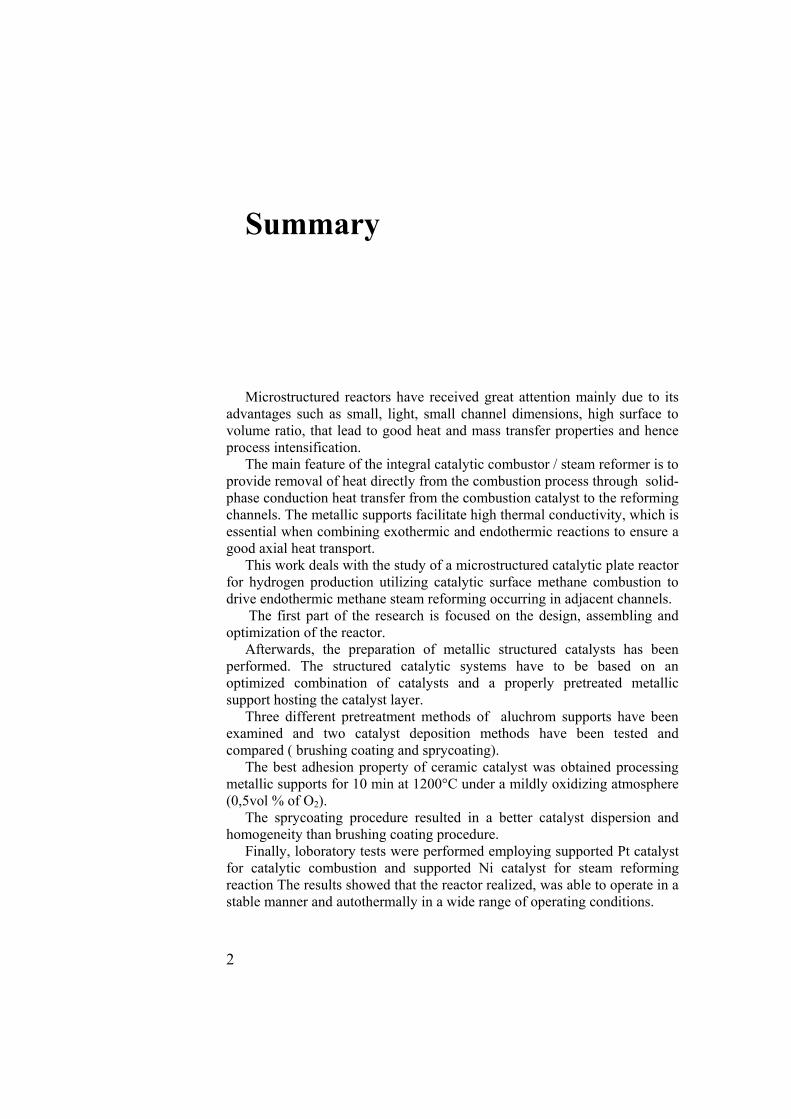
Summary Microstructured reactors have received great attention mainly due to its
advantages such as small, light, small channel dimensions, high surface to volume ratio, that lead to good heat and mass transfer properties and hence process intensification.
The main feature of the integral catalytic combustor / steam reformer is to provide removal of heat directly from the combustion process through solid-phase conduction heat transfer from the combustion catalyst to the reforming channels. The metallic supports facilitate high thermal conductivity, which is essential when combining exothermic and endothermic reactions to ensure a good axial heat transport.
This work deals with the study of a microstructured catalytic plate reactor for hydrogen production utilizing catalytic surface methane combustion to drive endothermic methane steam reforming occurring in adjacent channels.
The first part of the research is focused on the design, assembling and optimization of the reactor.
Afterwards, the preparation of metallic structured catalysts has been performed. The structured catalytic systems have to be based on an optimized combination of catalysts and a properly pretreated metallic support hosting the catalyst layer.
Three different pretreatment methods of aluchrom supports have been examined and two catalyst deposition methods have been tested and compared ( brushing coating and sprycoating).
The best adhesion property of ceramic catalyst was obtained processing metallic supports for 10 min at 1200°C under a mildly oxidizing atmosphere (0,5vol % of O2).
The sprycoating procedure resulted in a better catalyst dispersion and homogeneity than brushing coating procedure.
Finally, loboratory tests were performed employing supported Pt catalyst for catalytic combustion and supported Ni catalyst for steam reforming reaction The results showed that the reactor realized, was able to operate in a stable manner and autothermally in a wide range of operating conditions.
In the first chapter a description of the importance of the fuel cells as a promising alternative for battery packs in portable electronic devices and of the methane steam reforming and catalytic combustion processes is given.
In the second chapter some examples of microstructured reactors reported in scientific literature as well as of the structured catalysts employed are discussed.
In the third chapter the description of the reactor design and of the experimental set-up, of how tests have been carried out and the operating parameters investigated, is reported.
A thermodynamic evaluation of the steam reforming reaction has been carried out in order to identify the thermodynamically favourable operating conditions in which methane may be converted to hydrogen in the process.
Thus the influence of main parameters such as the temperature of reactants, molar feed ratio H2O/CH4 and the pressure of the reforming reactor have been investigated.
In the fourth chapter the preparation of supported catalysts, in particular the comparison of the three pretreatment procedures of supports and of the two washcoat deposition methods is decribed.
The characterization of samples was performed with the usual techniques such as N2 adsorption-desorption tests, X-ray diffractometry, spectroscopy analysis and vibration tests. The results of catalyst characterization are reported and discussed.
In the fifth chapter the results of catalytic activity tests performed are reported. To determine a stable window of operating conditions, experiments have been carried out to evaluate the effect that inlet conditions as residence time and H2O/CH4 ratio for steam reforming reaction, have on methane conversion and hydrogen yield.
A comparison between concurrent and countercurrent flows is illustrated. Temperature profiles and reformate compositions in the combustion and reforming channels are reported.
Experimental results showed that reforming reaction can be sustained with high methane conversion and to maintain combustion catalyst temperatures within the range where activity of both catalysts is high.
The reactor affords to operate autothermally for residence time range of millisecond order.

I Introduction
All over the world, every country is now conscious that fossil fuels consumption, releasing CO2 in the atmosphere, is leading the earth to dramatic ecological damages. Therefore, at the highest levels, ambitious programs intend to coordinate accademic research and industrial developments, in order to promote the use of hydrogen as tomorrow’s energy carrier. Hydrogen represents a clean and carbon-free energy vector, which can be used directly in internal combustion engines or converted to electrical energy by fuel cells, with only formation of water (Ogden, 2002).
However, the energy yield of thermal engines is limited by the Carnot heat-to-work cycle: 40% for the best machines like steam turbines, but often less than 20% for internal combustion engines. In comparison, fuel cells produce electricity directly from chemical reactions with a much higher efficiency, which can reach 50-60% for hydrogen-based fuel cells (Shinke, 2002).
I.1 Fuel cells and fuel processor
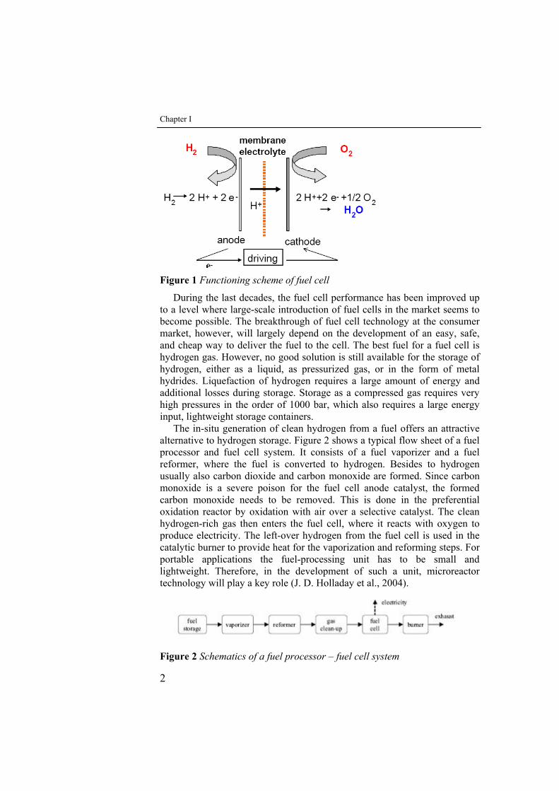
Fuel cells are regarded as a promising alternative for battery packs in portable electronic devices, given the much very high energy density of fuel cell systems (W. Donitz., 1998; Song,2002). Fuel cells (fig.1) are able to convert chemical energy directly to electricity with a high conversion efficiency.
Chapter I
2
Figure 1 Functioning scheme of fuel cell
During the last decades, the fuel cell performance has been improved up to a level where large-scale introduction of fuel cells in the market seems to become possible. The breakthrough of fuel cell technology at the consumer market, however, will largely depend on the development of an easy, safe, and cheap way to deliver the fuel to the cell. The best fuel for a fuel cell is hydrogen gas. However, no good solution is still available for the storage of hydrogen, either as a liquid, as pressurized gas, or in the form of metal hydrides. Liquefaction of hydrogen requires a large amount of energy and additional losses during storage. Storage as a compressed gas requires very high pressures in the order of 1000 bar, which also requires a large energy input, lightweight storage containers.
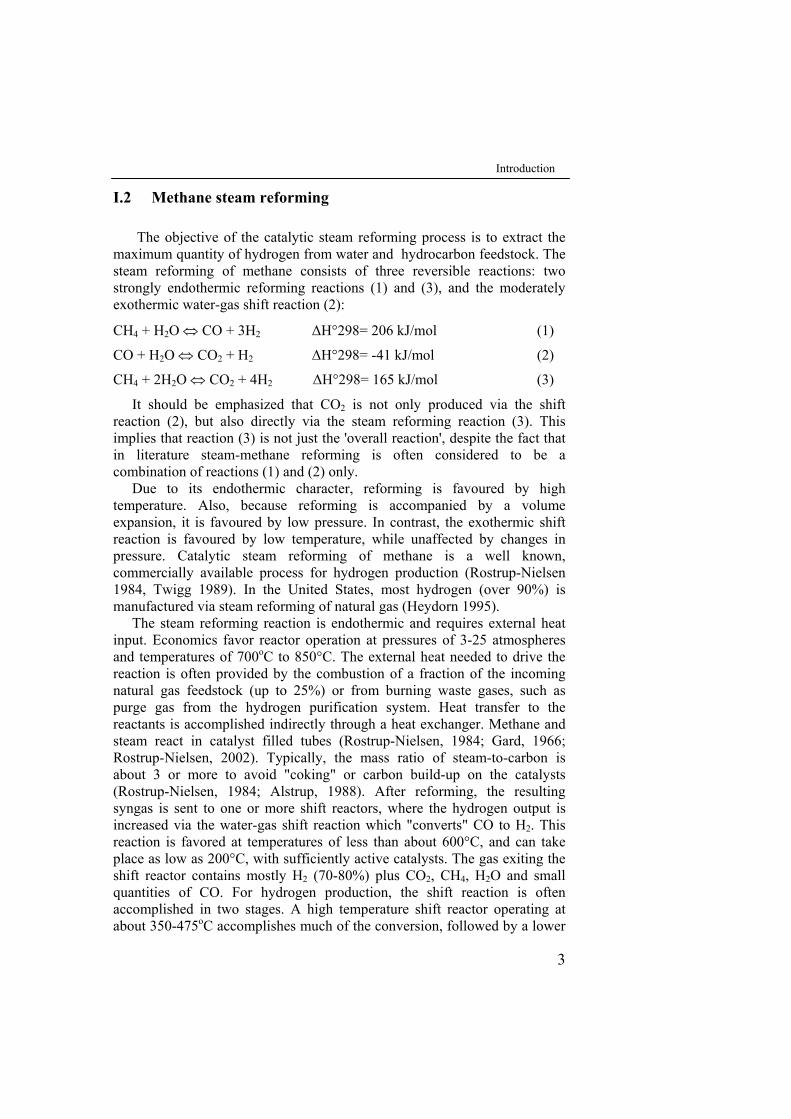
The in-situ generation of clean hydrogen from a fuel offers an attractive alternative to hydrogen storage. Figure 2 shows a typical flow sheet of a fuel processor and fuel cell system. It consists of a fuel vaporizer and a fuel reformer, where the fuel is converted to hydrogen. Besides to hydrogen usually also carbon dioxide and carbon monoxide are formed. Since carbon monoxide is a severe poison for the fuel cell anode catalyst, the formed carbon monoxide needs to be removed. This is done in the preferential oxidation reactor by oxidation with air over a selective catalyst. The clean hydrogen-rich gas then enters the fuel cell, where it reacts with oxygen to produce electricity. The left-over hydrogen from the fuel cell is used in the catalytic burner to provide heat for the vaporization and reforming steps. For portable applications the fuel-processing unit has to be small and lightweight. Therefore, in the development of such a unit, microreactor technology will play a key role (J. D. Holladay et al., 2004).
Figure 2 Schematics of a fuel processor – fuel cell system
Introduction
3
I.2 Methane steam reforming
The objective of the catalytic steam reforming process is to extract the maximum quantity of hydrogen from water and hydrocarbon feedstock. The steam reforming of methane consists of three reversible reactions: two strongly endothermic reforming reactions (1) and (3), and the moderately exothermic water-gas shift reaction (2):
CH4 + H2O ⇔ CO + 3H2 ΔH°298= 206 kJ/mol (1)
CO + H2O ⇔ CO2 + H2 ΔH°298= -41 kJ/mol (2)
CH4 + 2H2O ⇔ CO2 + 4H2 ΔH°298= 165 kJ/mol (3)
It should be emphasized that CO2 is not only produced via the shift reaction (2), but also directly via the steam reforming reaction (3). This implies that reaction (3) is not just the 'overall reaction', despite the fact that in literature steam-methane reforming is often considered to be a combination of reactions (1) and (2) only.
Due to its endothermic character, reforming is favoured by high temperature. Also, because reforming is accompanied by a volume expansion, it is favoured by low pressure. In contrast, the exothermic shift reaction is favoured by low temperature, while unaffected by changes in pressure. Catalytic steam reforming of methane is a well known, commercially available process for hydrogen production (Rostrup-Nielsen 1984, Twigg 1989). In the United States, most hydrogen (over 90%) is manufactured via steam reforming of natural gas (Heydorn 1995).
The steam reforming reaction is endothermic and requires external heat input. Economics favor reactor operation at pressures of 3-25 atmospheres and temperatures of 700oC to 850°C. The external heat needed to drive the reaction is often provided by the combustion of a fraction of the incoming natural gas feedstock (up to 25%) or from burning waste gases, such as purge gas from the hydrogen purification system. Heat transfer to the reactants is accomplished indirectly through a heat exchanger. Methane and steam react in catalyst filled tubes (Rostrup-Nielsen, 1984; Gard, 1966; Rostrup-Nielsen, 2002). Typically, the mass ratio of steam-to-carbon is about 3 or more to avoid "coking" or carbon build-up on the catalysts (Rostrup-Nielsen, 1984; Alstrup, 1988). After reforming, the resulting syngas is sent to one or more shift reactors, where the hydrogen output is increased via the water-gas shift reaction which "converts" CO to H2. This reaction is favored at temperatures of less than about 600°C, and can take place as low as 200°C, with sufficiently active catalysts. The gas exiting the shift reactor contains mostly H2 (70-80%) plus CO2, CH4, H2O and small quantities of CO. For hydrogen production, the shift reaction is often accomplished in two stages. A high temperature shift reactor operating at about 350-475oC accomplishes much of the conversion, followed by a lower
Chapter I
4
temperature (200-250oC) shift reactor which brings the CO concentration down to a few percent by volume or less.
Hydrogen is then purified. The degree of purification depends on the application. For industrial hydrogen, pressure swing absorption (PSA) systems or palladium membranes are used to produce hydrogen at up to 99.999% purity. For PEM or phosphoric acid fuel cells closely coupled to reformers, diluents such as CO2 and CH4 are tolerable.
However, CO must be reduced to less than about 10 ppm for PEM fuel cells, so a CO removal system such as preferential oxidation must be used.
In a preferential oxidation system, the gas is passed over a catalyst bed, with added air. At certain temperature and stoichiometry conditions, the reaction
CO + 1/2 O2 CO2 (4)
is strongly favored over hydrogen oxidation, so that CO is removed to the level of several ppm. Preferential oxidation technology is being developed for use with reformers in fuel cell cogeneration systems or onboard fuel cell vehicles.
The energy conversion efficiency [= hydrogen out (HHV)/energy input (HHV)] of large scale steam methane reformers is perhaps 75-80%, although 85% efficiencies might be achieved with good waste heat recovery and utilization (Katofsky 1993).
I.2.1 Reaction rates and kinetics
Many studies have been performed to investigate the kinetics of steam reforming, and while there is general agreement on first order kinetics with respect to methane, the reported activation energies span a wide range of values. This might be explained by experimental inaccuracies due to transport (diffusion and heat transfer) restrictions.
The effect of diffusion limitation is exemplified by the work of Bodrov and co-workers, who found that the reaction rate of methane on a conventional nickel/alumina catalyst depends only on the partial pressure of methane, whereas on a nickel foil (having less diffusion restrictions) the rate depends also on the partial pressures of H2O, H2, and CO (Bodrov, 1964; Bodrov, 1967). However several accurate and reliable investigations have been performed, acknowledging the possibility of diffusional limitations. For instance, an extensive study of the intrinsic kinetics of the reforming and water-gas shift reactions on a Ni/MgAl2O4-spinel catalyst was performed by
Xu and Froment (Xu et Froment, 1989). They developed a model, based on a Langmuir-Hinshelwood reaction mechanism, which includes as many as 13 reaction steps.
In general, the rate equations of the steam reforming reactions (1–3) can be written as:
Introduction
5
H CO, ,CO O,H ,CH x1,2,3;i );C,(P/Z)K,(Pfkr 2224xx2
xxiii === (5)
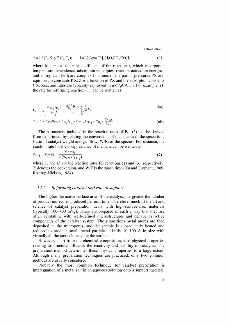
where ki denotes the rate coefficient of the reaction i, which incorporate temperature dependence, adsorption enthalpies, reaction activation energies, and entropies. The fi are complex functions of the partial pressures PX and equilibrium constants KX. Z is a function of PX and the adsorption constants CX. Reaction rates are typically expressed in mol/gCAT/h. For example, r1, the rate for reforming reaction (1), can be written as:
(6b) P
PCPCPCPC1Z
(6a) ;ZK
PP
P
PPkr
2
224422
2
2
24
H
OHOHCHCHHHCOCO
2
1
CO0.5H
2.5H
OHCH11
++++=
⎟⎟⎟
⎠
⎞
⎜⎜⎜
⎝
⎛−=
The parameters included in the reaction rates of Eq. (5) can be derived
from experiment by relating the conversions of the species to the space time (ratio of catalyst weight and gas flow, W/F) of the species. For instance, the reaction rate for the disappearance of methane can be written as:
(7) )/Fd(W
dXrrr
4
44
CHcat
CH31CH =+=
where r1 and r3 are the reaction rates for reactions (1) and (3), respectively, X denotes the conversion, and W/F is the space time (Xu and Froment, 1989; Rostrup-Nielsen, 1984).
I.2.2 Reforming catalyst and role of support
The higher the active surface area of the catalyst, the greater the number of product molecules produced per unit time. Therefore, much of the art and science of catalyst preparation deals with high-surface-area materials (typically 100–400 m2/g). These are prepared in such a way that they are often crystalline with well-defined microstructures and behave as active components of the catalyst system. The (transition) metal atoms are then deposited in the micropores, and the sample is subsequently heated and reduced to produce small metal particles, ideally 10–100 Å in size with virtually all the atoms located on the surface.
However, apart from the chemical composition, also physical properties relating to structure influence the reactivity and stability of catalysts. The preparation method determines these physical properties to a large extent. Although many preparation techniques are practiced, only two common methods are usually considered.
Probably the most common technique for catalyst preparation is impregnation of a metal salt in an aqueous solution onto a support material,
(7)
(6a)
(6b)
Chapter I
6
e.g., γ-Al2O3, while another frequent method of preparation is co-precipitation. In this procedure, solutions of metal salts are added together, usually at constant pH, and precipitate into the desired product. A general treatment after the synthesis is calcination (heating the sample in air, in order to 'clean up' and 'stabilize' the catalyst) and/or reduction (heating the sample in a reducing atmosphere, usually containing hydrogen), in order to activate the catalytic metal) of the catalyst. Li and Chen (1994), in their temperature-programmed-reduction studies of nickel oxide/alumina catalysts showed that the H2 consumption was strictly related to the Ni content and that the rate of reduction was enhanced if high nickel loadings were considered. However, a deeper insight to the reduction process of steam reforming catalysts was given byRichardson et al.: they monitored the conversion of NiO on α-Al2O3 via X-ray diffraction in metallic Ni, clearly showing the effects of additives in the reduction kinetics (Richardson et al., (2004); Richardson et al., (1996)).
Also the metal precursor used to impregnate the support, as well as the calcination and reduction procedures (i.e., temperature, time, and gas composition) strongly affect the catalytic properties of the prepared catalyst. For instance, Wang and Lu also studied the effect of the nickel precursor on the activity of Ni/ γ-Al2O3 catalysts for the reforming of methane (Wang, 1998c). They concluded that catalysts derived from inorganic precursors (e.g.,nickel nitrate) are more active and stable than organic-derived precursors. Matsumura et al. (Matsumura, 2004) found that Ni/γ-Al2O3 is not very active for steam reforming when reduced at 500°C; only after reduction at 700°C, Ni/ γ-Al2O3 will be fairly active. Similar results concerning the reduction procedure were found by Wang and Lu in yet another study on the reforming of methane with Ni/MgO catalysts (Wang, 1998a). They ascribe this effect to the fact that a solid-solution of NiO and MgO exists, which is more difficult to activate. Therefore, identifying a catalyst on the basis of its chemical composition only (e.g., 15wt% Ni/γ-Al2O3), does not provide much information about its stability or activity.
For steam-reforming, usually Ni or the noble metals Ru, Rh, Pd, Ir, Pt are used as the active metal in catalysts. Because of its low costs, Ni is the most widely used metal from this set. Ni, however, is not the most active and usually it is more prone to deactivation by, e.g., carbon formation or oxidation. The synergism between different metals has also been investigated. For instance, Rh-promoted Ni/γ-Al2O3 was found to possess higher activity than either Ni/γ-Al2O3 or Rh/γ-Al2O3 catalysts in the methane reforming with CO2 (Hou, 2003). In this case, Rh improved the dispersion of Ni, retarded the sintering of Ni, and increased the activation of CO2 and CH4.
Wang et al.(2004), developing a Rh catalyst for methane steam reforming in microchannel chemical reactors, demonstrated that Rh loading on a stable MgO–Al2O3 support is able to improve the volumetric productivity for methane conversion. Catalyst activities were stable over a
Introduction
7
wide range of steam/carbon ratios and, in particular, experimental results showed that Rh/MgO–Al2O3 catalysts were extremely active for methane steam reforming and resistant to coke formation at stoichiometric steam/carbon ratio of 1 for over 14 h time-on-stream with no sign of deactivation.
The activity of a catalyst is related to the metal surface area (i.e., the number of active sites). This implies that, generally, the catalytic activity benefits from a high dispersion of the metal particles. Common dispersions for Ni catalysts are of 2–5%, with metal particles of 20–50 nm (Rostrup-Nielsen, 1984). There is an optimum beyond which an increase in Ni-content does not produce any increase in activity, usually around 15–20 wt% (depending on support structure and surface). Although the nickel surface area is generally increased with higher loadings, the dispersion or utilization of the nickel tends to decrease with increasing nickel content. Hence, the activity will not increase any further.
This result is confirmed also by the work of Dong et al. (2002); they showed that the strong interaction between NiO and the surface of Ce-ZrO2 increased the conversion of methane in steam reforming reaction with increasing nickel content up to 15 wt.% and then decreases above this value.
The role of the support is fundamental for the catalytic activity. It not only determines the dispersion of the catalytically active metal particles or the catalyst’s resistance to sintering, it also affects the reactivity and coke resistance of the metal particles, and may even participate in the catalytic reaction itself.
In first instance, the role of the support is – literally – to provide a support for the catalytically active metal, in order to obtain a stable and high active surface area. Among the most common supports for methane reforming there are α- and γ-Al2O3, MgO, MgAl2O4, SiO2, ZrO2, and TiO2. These supports have good porosity, which results in a long contact-time between reactants and catalyst. Maintaining a high active surface area is also important: the support can affect the migration and coalescence of metal particles (i.e., sintering) in various ways. Pore structure, morphology, and phase transitions of the support determine the final particle size.
Furthermore, due to the nature of the chemical bonding between the support and the metal atoms, the electronic properties – and hence the reactivity of the metal is affected. For instance, acidity in the support is known to facilitate the decomposition of methane, but it will also promote cracking and polymerization, producing carbon. In general, a strong interaction between metal and support makes a catalyst more resistant to sintering and coking, thus resulting in a longer time of catalyst stability (Wang, 1998b). Bradford et al. (Bradford, 1996) found for Ni/MgO catalysts that formation of a partially educible NiO–MgO solid solution appeared to stabilize surface Ni–Ni bonds and prevent carbon diffusion into nickel particles. They suggest that indeed the support influences the catalyst
Chapter I
8
activity by altering the electron donating ability of the reduced nickel surfaces. In addition they found that a strong metal-support interaction emerges for Ni/TiO2 catalysts which leads to blockage of the active nickel sites due to migration of TiOx-species from the TiO2-carrier (Zhang, 1996; Bradford, 1996; Takatani, 1984). Partly as a result of this site blocking, carbon formation is drastically reduced on Ni/TiO2. In contrast, it was concluded that a lack of metal-support interaction in Ni/SiO2 permitted substantial formation of filamentous whisker carbon.
The effect of the support on the electronic properties of the catalytically active metal is also illustrated by Yokota and co-workers (Yokota, 2002). They found that 0.5 wt% Rh on SiO2 is more active than 0.5 wt% Rh on γ-Al2O3 for the CH4 reforming reaction with CO2 at 700°C, despite the higher dispersion of Rh on γ-Al2O3. This seemingly contradictory result is probably caused by the fact that a stronger metal-support interaction exists for Rh on γ-Al2O3. Accordingly, the Rh/γ-Al2O3 system tends to maximize its number of metal-support bonds, resulting in a higher dispersion. Then, as a consequence of this stronger metal-support interaction, Rh loses its metallic character (i.e., electrons are withdrawn from Rh) and because of that, Rh possesses a rather cationic character on γ-Al2O3, resulting in the formation of less reactive Rh2O3-like structures.
For amorphous CeO2 as a support for Pd catalysts, a strong metal-support interaction leads to partial encapsulation of Pd particles, resulting in significantly reduced catalytic activity for steam reforming (Craciun, 2002). For more complex supports, synergetic effects can emerge. For instance, Ni supported on MgO–CaO showed high basicity and lower coke forming ability, attributed to the addition of CaO (Yamazaki, 1992). Al2O3–CeO2 is known for its catalytic stability and coking resistance, whereas CeO2 itself may lead to significantly reduced catalytic activity (Wang, 1998a). In the case of the combined Al2O3–CeO2 support, the beneficial effects (i.e., high porosity and increased stability) of both supports are utilized (Craciun, 2002; Wang, 1998d) – at least, when crystalline (i.e., oxidized) instead of amorphous (i.e., reduced) CeO2 is used. In fact, CeO2 is actually contributing the reaction mechanism itself.
The support may also actively participate in the catalytic reaction itself. For instance, supports with a basic nature, such as MgO, are known to enhance the activation of steam (i.e.,dissociation into reactive OH and H species). Also, stabilization of different CHx-intermediates contributes to the overall reaction mechanism.
An important factor for catalyst reactivity and stability lies in the catalyst’s resistance to carbon deposits, which could lead to active site blocking. Apart from directly altering the metal’s properties by additives, an alternative route is to use a support which suppresses carbon deposition. This can be achieved with so-called oxy-transporters, such as ZrO2 or CeO2, which are capable of oxidizing deposited carbon. Additionally, because of
Introduction
9
their oxygen conducting properties, these supports can actively participate in the catalytic reaction by oxidizing or reducing reaction intermediates.
The role of ceria-containing supports has attracted a lot of attention in recent catalyst research. Especially CeO2–Al2O3, CexZr1-xO2, and CeZrOx–Al2O3 supports are extensively investigated. For instance, Dong and co-workers investigated methane reforming over Ni/Ce0,15Zr0.85O2 catalysts (Dong, 2002). They concluded that two kinds of active sites exist, one for methane activation (on Ni) and one for steam or oxygen activation (on the CexZr1-xO2-support). Due to the addition of ceria, the ability to store, release, and transfer oxygen species is acquired, resulting in an enhanced ability to prevent carbon formation that would normally accumulate on the metal or metal-support interface.
Methane steam reforming over Ni catalyst supported on Ce–ZrO2 was studied at 650–900 °C in conditions where the influence of mass transfer limitations could be considered negligible (Laosiripojana ,2005). At 900 °C, Ni/Ce–ZrO2 with Ce/Zr ratio of 3/1 showed the best performance in term of activity and stability. The resistance toward carbon formation over this catalyst was higher than that over conventional Ni/Al2O3 at the same operating conditions even if a slight deactivation due to the sintering was observed over Ni/Ce–ZrO2 at these high temperature conditions.
Another intriguing example of active involvement of the support during the reforming of CH4 was observed by Zhang and Verykios (Zhang, 1996; Verykios, 2003). They reported that the Ni/La2O3 catalyst showed high stability during the reaction of CH4 with CO2, because an alternate reaction pathway occurred at the Ni/La2O3 interface. They proposed a mechanism in which CH4 mainly cracks on the Ni crystallites to form H2 and surface carbon species (CHx), while CO2 preferably adsorbs on the La2O3 support to form La2O2CO3 species. The nickel particles are partially covered by these La2O2CO3 species, which participate directly in reactions with surface carbon species on the neighbouring Ni sites to form CO. Due to the existence of such synergetic sites which consist of Ni and La elements, the deposited carbon on the Ni sites is favourably removed by the oxycarbonate species originating from La2O2CO3, thus resulting in an active and stable performance.
However adverse effects in the use of La-modified support were shown in the study of Navarro et al. (2005) for the oxidative reforming of ethanol over Pt catalysts. On the basis of the activity results, the catalytic behaviour of supported Pt catalysts towards the production of hydrogen from ethanol was strongly promoted by the presence of Ce on the support, in contrast with the presence of lanthanum, which did not promote the degree of ethanol conversion. The poorer performance of the La-containing sample was associated with the lower Pt dispersion achieved on this sample. When cerium and lanthanum were present in the support, a poorer catalytic behaviour was observed as a consequence of the lower Pt–Ce interaction
Chapter I
10
derived from the decrease in surface ceria dispersion with respect to that achieved on the lanthanum-free ceria–alumina support.
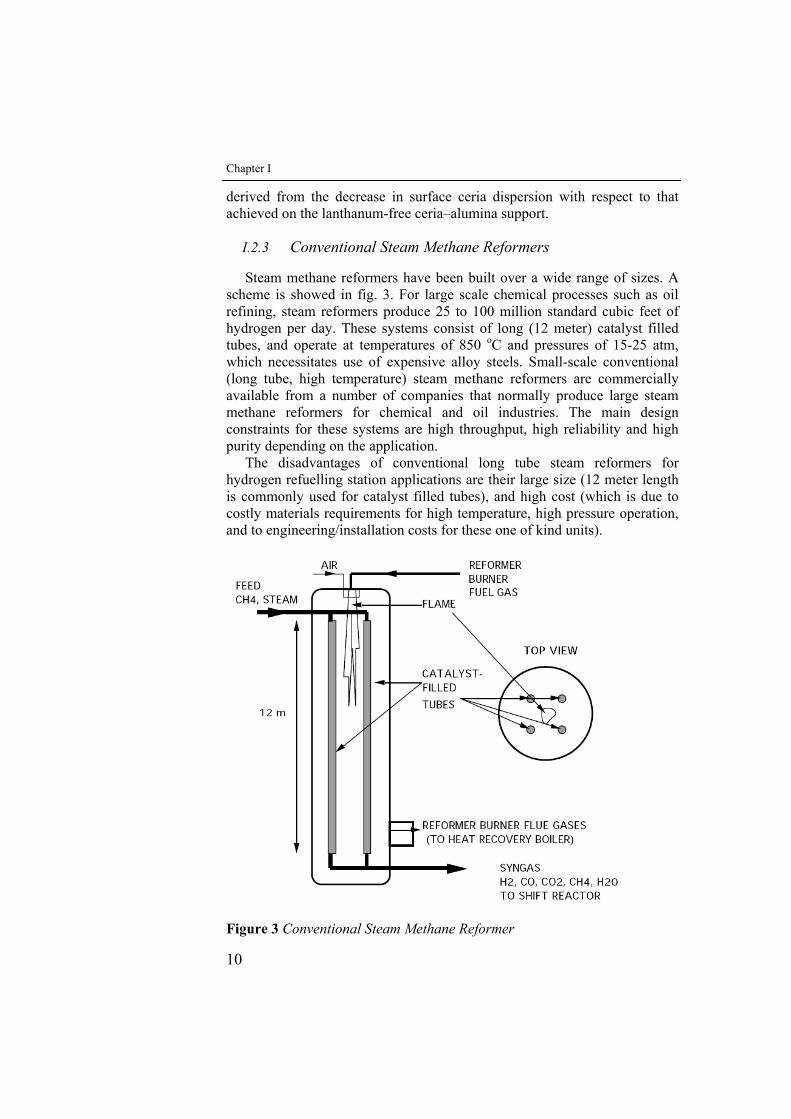
I.2.3 Conventional Steam Methane Reformers
Steam methane reformers have been built over a wide range of sizes. A scheme is showed in fig. 3. For large scale chemical processes such as oil refining, steam reformers produce 25 to 100 million standard cubic feet of hydrogen per day. These systems consist of long (12 meter) catalyst filled tubes, and operate at temperatures of 850 oC and pressures of 15-25 atm, which necessitates use of expensive alloy steels. Small-scale conventional (long tube, high temperature) steam methane reformers are commercially available from a number of companies that normally produce large steam methane reformers for chemical and oil industries. The main design constraints for these systems are high throughput, high reliability and high purity depending on the application.
The disadvantages of conventional long tube steam reformers for hydrogen refuelling station applications are their large size (12 meter length is commonly used for catalyst filled tubes), and high cost (which is due to costly materials requirements for high temperature, high pressure operation, and to engineering/installation costs for these one of kind units).
Figure 3 Conventional Steam Methane Reformer
Introduction
11
I.3 Methane combustion
I.3.1 Thermodynamics
The combustion intensity between a fuel and an oxidizer depends on their relative concentrations. When their concentration ratio is chemically correct in that all the reactants can be totally consumed in the reaction, then the combustion intensity is close to the highest and this mode corresponds to burning stoichiometric combustion.
For methane reacting with oxygen, producing only water and carbon dioxide, the chemical equation, stoichiometrically balanced, is expressed as:
CH4+2O2 ⇒ 2H2O+CO2 ΔH°298=-803,2 kJ/mol (8)
For most of the practical combustion devices generating heat and power, the oxidizer is simply the oxygen in air. For practical calculations air can be considered to consist of 21 percent oxygen and 79 percent nitrogen in molar concentrations, implying that for every mole of oxygen there are 3.76 moles of nitrogen. Therefore, we can write: Air = 0.21O2 + 0.79N2 or 4.76Air = O2 + 3.76N2. Since most of air is nitrogen, which is basically inert as far as the bulk chemical heat release is concerned, the combustion temperature and, hence, intensity are reduced because of the expenditure of thermal energy used to heat it up during the course of burning. Therefore, for applications requiring intense burning, either oxygen-enriched air or even pure oxygen is used.
To show the concentrations of fuel and oxidizer in a mixture, we have to consider that combustion of methane can produce carbon dioxide or carbon monoxide depending on the O2(Air)/CH4 ratio:
CH4 + O2 ⇔ 2H2 + CO2 ΔH°298= -319 kJ/mol (9)
CH4 + 0,5O2 ⇔ 2H2 + CO ΔH°298= -36 kJ/mol (10)
CH4 + 2O2 ⇒ 2H2O + CO2 ΔH°298= -803,2 kJ/mol (11)
Other reaction may also be involved to a greater or lesser extent. These could include steam reforming (12) and water gas shift (13) reactions:
CH4 + H2O ⇔ CO+3H2 ΔH°298= 206 kJ/mol (12)
CO+ H2O ⇔ CO2+H2 ΔH°298= -41 kJ/mol (13)
Equation 11 is theoretical: it presumes that all the oxygen and fuel react and that nitrogen does not. Actually, trace amount of nitrogen may react with oxygen to form nitrogen oxides (NOx). In this context the amount of reacting nitrogen is too small to be considered. In industrial practice, perfect mixing cannot be achieved; it is more cost-effective to ensure complete combustion with the addition of excess air. However, if one does not provide enough air, combustion may still continue, generating large quantities of CO
Chapter I
12
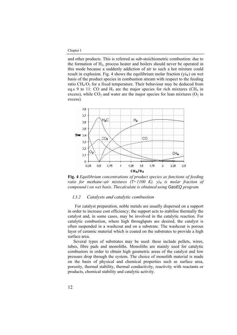
and other products. This is referred as sub-stoichiometric combustion: due to the formation of H2, process heater and boilers should never be operated in this mode because a suddenly addiction of air to such a hot mixture could result in explosion. Fig. 4 shows the equilibrium molar fraction (yiW) on wet basis of the product species in combustion stream with respect to the feeding ratio CH4/O2 for a fixed temperature. Their behaviour may be deduced from eq.s 9 to 11: CO and H2 are the major species for rich mixtures (CH4 in excess), while CO2 and water are the major species for lean mixtures (O2 in excess).
Fig. 4 Equilibrium concentrations of product species as functions of feeding ratio for methane–air mixtures (T=1100 K). yiW is molar fraction of compound i on wet basis. Thecalculate is obtained using GasEQ program.
I.3.2 Catalysts and catalytic combustion
For catalyst preparation, noble metals are usually dispersed on a support in order to increase cost efficiency; the support acts to stabilise thermally the catalyst and, in some cases, may be involved in the catalytic reaction. For catalytic combustion, where high throughputs are desired, the catalyst is often suspended in a washcoat and on a substrate. The washcoat is porous layer of ceramic material which is coated on the substrates to provide a high surface area.
Several types of substrates may be used: these include pellets, wires, tubes, fibre pads and monoliths. Monoliths are mainly used for catalytic combustors in order to obtain high geometric areas of the catalyst and low pressure drop through the system. The choice of monolith material is made on the basis of physical and chemical properties such as surface area, porosity, thermal stability, thermal conductivity, reactivity with reactants or products, chemical stability and catalytic activity.
Introduction
13
Special metal alloys or ceramics are usually used for fabrication of substrates, depending on the required operating temperature. Metal alloys, which are made of iron, chrome and aluminium, provide excellent mechanical properties and a thinner cell wall, but their thermal stability is not as high as ceramics. Therefore, ceramics have been used far more than metal alloys in the past. The most common high-temperature ceramics are based on alumina (Bittence, 1977) which is relatively inexpensive and reasonably resistant to thermal shock. The alumina is taken with other materials such as silica and chromium: mullite (3Al203-Si02) and cordierite (2MgO-5SiO2-2Al2O3) are among the most frequently used substrates. One good candidate for substrates is zirconia since the oxide can be used at the highest temperature (2210°C) among the ceramics and shows excellent inertness to most metals (Prasad, et al., 1984).
Metal oxides and noble metals such as Pt, Rh and Pd were used as catalysts for the catalytic oxidation of methane. Noble metal catalysts showed higher activity than metal oxide catalysts (Anderson et al., 1961; Arai et al., 1986). They can be used either with or without a support, but supported catalysts are favoured for the oxidation. One particular advantage of supported metal catalysts is that the metal is dispersed over a greater surface area of the support and shows different activity from the unsupported metals due to interactions of the metal with the support. The support also reduces thermal degradation. The application of noble metals other than Pt and Pd in catalytic combustion is limited practically because of their high volatility, ease of oxidation and limited supply. Palladium and platinum are, then, the most widely used catalysts for the catalytic oxidation of methane.
Supported palladium is reported to be the most active noble metal catalyst for low temperature lean conditions (Gelin et al. 2002). This characteristic makes palladium particularly attractive for combustion applications where low reaction temperatures are critical to achieving ultra low emissions of NOx and other pollutants (Forzatti et al. 1999). Palladium based catalysts undergo a hysteretic oxidation/reduction cycle marked by a reduction of PdO to Pd between 700 and 800°C depending on the partial pressure of O2. Reoxidation of Pd to PdO occurs at lower temperatures around 650°C (Farrauto et al. 1992; Wolf et al. 2003). This hysteresis loop can greatly affect the activity of the catalyst and the stability of any system utilizing palladium, particularly for CH4 combustion. The phase transformation has prompted discussion regarding the most active phase of palladium for high temperature combustion applications. Some researchers argue that the oxidized state is most active (Farrauto, et al. 1992; Burch et al. 1995) while others contest that the reduced form is preferred (Lyubovsky et al. 1999). Others have proposed alternative mechanisms for describing the active surface involving a mixed Pd/PdO state (Lyubovsky et al. 1998) or where pairs of oxygen atoms and vacancies are present (Fujimoto et al. 1998). The uncertainty of Pd oxidation states and their activity leads to
Chapter I
14
complex reactor behaviour that is still under investigation for catalytic combustor development. Similar studies, to check the effects of preparation treatments were performed by Roth et al., (2001): Pd and Pt catalysts were prepared, characterised and tested with respect to the low-temperature combustion of methane after reduction in H2 and ageing under reactants at 600°C. In the case of Pd, the use of SnO2 or SnO2-based supports led to catalysts slightly less active than Pd/Al2O3. In contrast, SnO2 was found to strongly promote the oxidation of methane over Pt catalysts with respect to Pd/Al2O3, even after ageing under reactants. When Pt was supported on SnO2 grafted on Pd/Al2O3, the activity was found at most similar to or, after ageing, lower than Pt/Al2O3.
Generally, for the catalytic combustion of methane, the support plays an important part in determining the activity and long-term stability of the catalysts. These effects have been investigated in some details (Trimm, 1980; Baldwin, Niwa, et al., 1983; Cullis, et al., 1983). To investigate the effect of support on the activity of catalysts, methane oxidation over Pd and Pt catalysts supported on various metal oxides has been studied (Niwa, et al., 1983; Cullis, et al., 1983). The oxidation of methane was carried out over Pt catalysts on Al2O3, SiO2- Al2O3 and SiO2 (Niwa et al., 1983). It was found that the activity of catalysts decreased in the order: Pt/SiO2-Al2O3 > Pt/ Al2O3 > Pt/SiO2. The dispersion of Pt on supports was found to be proportional to the activity of catalysts. However, for palladium catalysts reduced with hydrogen, Pd/SiO2 catalyst was more active than Pd/ Al2O3
catalyst (Hoyos, et al., 1993). For γ-Al2O3, TiO2 and ThO2 supports, the activities of both Pt and Pd catalysts decrease in the order: γ-Al2O3 > TiO2 > ThO2 (Cullis et al., 1983)
The oxidation of methane over various catalysts was studied by many researchers using catalysts based on both noble metals and metal oxides such as Co3O4, Co3O4/alumina, ZnCrO4, CuCrO4, PbCr04, Cr2O3/alumina, CuO/alumina and CeO2/alumina (Anderson, et al., 1961). The Co3O4 catalyst was the most active metal oxide catalyst, but the activity was much less than Pd/alumina catalysts. Various perovskite-type oxides have also been tested for the catalytic oxidation of methane (Arai et al., 1986). The highest activity metal oxide catalyst was La0,6Sr0,4MnO3 which showed similar activity to Pt/alumina catalyst at a conversion level below 80%. However, unlike the Pt/alumina catalyst, the increase in activity with increasing temperature was significantly suppressed at high conversion levels. During the catalytic oxidation of methane, it was observed that some carbon was deposited on the catalysts (Cullis et al., 1971; Baldwin et al., 1990). This carbon has almost no effect on the activity of the catalysts, and it was found that the rate of methane oxidation was independent of the deposition of carbon on Pd catalysts (Cullis et al., 1971). It was also reported that the deposition of carbon on Pt catalyst first reduced activity but that this recovered in 15 min (Trimm et Lam, 1980).
Introduction
15
The feeding ratio (O2/CH4) has a strong effect on the total oxidation of methane to CO2. Under oxygen-rich conditions, methane is oxidized to carbon dioxide over Pt and Pd supported on alumina (Trimm et Lam, 1980; Mouaddib, et al.1992; Oh, et al., 1992). However, under oxygen-deficient conditions, the formation of carbon monoxide was observed over Pt/Al2O3, Pd/Al2O3 and Rh/Al2O3 catalysts (Trimm et Lam, 1980; Mouaddib, et al.1992; Oh, et al., 1992) showing that the selectivity to carbon monoxide was dependent on temperature. Under oxygen-deficient conditions, the conversion of methane to CO2 and water increased with increasing temperature up to full consumption of oxygen. At this point, the formation of CO was observed while the partial pressure of CO2 remained almost constant (Mouaddib, et al., 1992). As the temperature kept increasing, the selectivity to CO increased and CO became the main product under low O2/CH4 ratios. This is in good agreement with the results of Trimm and Lam (1980), who observed the formation of CO at high temperatures.
Also the effect of Pt and Pd loading on the support on the oxidation of methane was investigated (Niwa, et al., 1983; Cullis et Willatt, 1983; Otto, K., 1989). For conversions of methane less than 10% (kinetic controlied region: area B in Fig. 1), the oxidation rate of methane increased with an increase in Pt loading over the range of 0.1-2.0 wt% (Niwa, et al., 1983). Similarly, an increase in Pd or Pt loading (2.7-10 wt%) on γ-Al2O3 increased the overall rate of methane oxidation. However, although the increase in the overall rate of methane oxidation was observed, the activity per unit metal surface area decreased with an increase in loading (Cullis et Willatt, 1983). Pd/TiOz catalysts also showed the sarne trend. The effect of Pt loading on methane oxidation was investigated over the range 0.027-100 wt% (Otto, K., 1989). Below 1.4 wt% of Pt loading, the oxidation rate was almost constant, while, above 1.4 wt%, the rate increased with an increase in Pt loading to reach a maximum at about 5 wt%. Above 10 wt%, the reaction rate decreased significantly. Similar results have been observed by various authors (Niwa, et al., 1983; Cullis et Willatt, 1983; Otto, K., 1989).
I.3.3 Reaction rate and kinetic
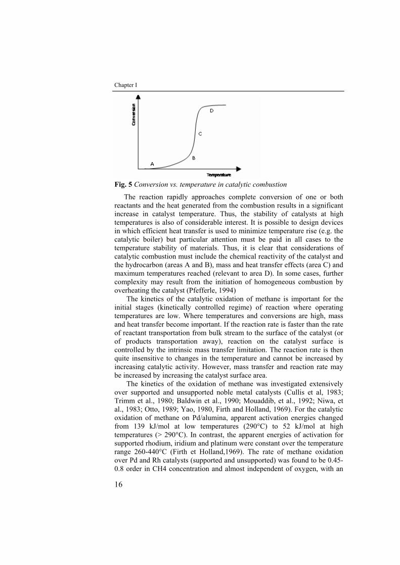
The general pattern of catalytic combustion of hydrocarbons is well established (Fig. 5). As temperature is increased, oxidation is initiated at a temperature that depends on the hydrocarbon and the catalyst. A further increase in temperature leads to an exponential increase in rate (area B in Fig. 1) to the point where heat generated by combustion is much greater than heat supplied. The reaction becomes mass transfer controlled (area C) until the reactants are depleted (area D).
Chapter I
16
Fig. 5 Conversion vs. temperature in catalytic combustion
The reaction rapidly approaches complete conversion of one or both reactants and the heat generated from the combustion results in a significant increase in catalyst temperature. Thus, the stability of catalysts at high temperatures is also of considerable interest. It is possible to design devices in which efficient heat transfer is used to minimize temperature rise (e.g. the catalytic boiler) but particular attention must be paid in all cases to the temperature stability of materials. Thus, it is clear that considerations of catalytic combustion must include the chemical reactivity of the catalyst and the hydrocarbon (areas A and B), mass and heat transfer effects (area C) and maximum temperatures reached (relevant to area D). In some cases, further complexity may result from the initiation of homogeneous combustion by overheating the catalyst (Pfefferle, 1994)
The kinetics of the catalytic oxidation of methane is important for the initial stages (kinetically controlled regime) of reaction where operating temperatures are low. Where temperatures and conversions are high, mass and heat transfer become important. If the reaction rate is faster than the rate of reactant transportation from bulk stream to the surface of the catalyst (or of products transportation away), reaction on the catalyst surface is controlled by the intrinsic mass transfer limitation. The reaction rate is then quite insensitive to changes in the temperature and cannot be increased by increasing catalytic activity. However, mass transfer and reaction rate may be increased by increasing the catalyst surface area.
The kinetics of the oxidation of methane was investigated extensively over supported and unsupported noble metal catalysts (Cullis et al, 1983; Trimm et al., 1980; Baldwin et al., 1990; Mouaddib, et al., 1992; Niwa, et al., 1983; Otto, 1989; Yao, 1980, Firth and Holland, 1969). For the catalytic oxidation of methane on Pd/alumina, apparent activation energies changed from 139 kJ/mol at low temperatures (290°C) to 52 kJ/mol at high temperatures (> 290°C). In contrast, the apparent energies of activation for supported rhodium, iridium and platinum were constant over the temperature range 260-440°C (Firth et Holland,1969). The rate of methane oxidation over Pd and Rh catalysts (supported and unsupported) was found to be 0.45-0.8 order in CH4 concentration and almost independent of oxygen, with an
Introduction
17
( ) ( )( )2422 OCH12OHOH /CC/kkCK1 >>+
apparent activation energy of 71-100 kJ/mol. These results were explained by the observation that, under O2-rich conditions, the surfaces of Pd and Rh catalysts were covered with O2 (as expected from thermodynamic considerations) and thus the oxidation of methane was independent of O2 concentration. However, platinum has a relatively high ionization potential compared to Pd and Rh and the oxide is of lower stability. Therefore, the oxygen coverage on Pt is expected to be less than on Pd and Rh (Yao, 1980).
Unlike the studies carried out with a considerable excess of O2 the oxidation rates determined under O2-deficient conditions were thus strongly dependent on oxygen concentration (Trimm et al., 1980). This effect can be explained, modelling the kinetics of the methane oxidation reaction by fitting the experimental data using a power law rate expression, with the rate of reaction proportional to the partial pressure of methane and oxygen:
mO
nCHCH 244
PkPr =− (12)
Accordingly, for lean mixture (O2 in excess), the combustion reaction is expressed as:
CH4RTEa
0CH4 Cekr- ⋅⋅=−
(13) with the kinetic parameters available in literature (i.e. Perry et Green ,
1997). Assuming a redox reaction mechanism (Golodets, 1983), the following
rate expression can be derived for the oxidation of methane (without water inhibition effects):
( )( )24
4
42
42
OCH12
CH2
CH2O1
CH2O1CH4 /CC/kk1
Ck
CkCk
CkCkr-
+=
+= (14)
If the concentration of oxygen is relatively large and k1>>k2 (that is, 1>> ( )( )
24 OCH12 CC/kk , then eq. (14) can simplify to an expression that is first order in methane and zero order in oxygen.
Cullis and Willatt (1984) reported that large amounts of added water inhibited the catalyst activity, although inhibition was not reported from the water produced by the oxidation of methane, that is, if no water was added. Burch, Urbano, and Loader (1995) reported strong water inhibition on palladium catalysts supported on silica and alumina. Eq. 14 can be extended to include water inhibition. Assuming that the water adsorbs on oxygen sites (Beld, Bijl, Reinders, Werf, & Westerterp, 1994; Golodets, 1983) the resulting rate expression is
( )( )2422
4
OCH12OHOH
CH2CH4 /CC/kkCK1
Ckr-
++=
(15) Provided that
, then eq. 15 reduces to
Chapter I
18
OHOH
CH2CH4
22
4
CK1
Ckr-
+=
(16) If a large amount of water is present, such as may be the case in a
secondary combustion application, then the water concentration will be
essentially constant and OHOH 22CK1 << . In this case, the oxidation rate will
have the appearance of a pseudo-first order reaction. Furthermore, the reaction order with respect to water under such conditions would appear to be equal to −1.
In the catalytic combustion of methane, both heterogeneous and homogeneous reactions may be recognized. At low temperatures (kinetically controlled region), the heterogeneous reactions are dominant and the homogeneous reaction rates are unimportant. At high temperatures, the homogeneous reactions become more important. Several models have been proposed for such systems (Harnson et Ernest, 1978; Bruno, et al., 1983).
Harrison and Ernest (1978) developed a two dimensional model for the combustion of CO in an adiabatic laminar reactor. Three variations of the model (the homogeneous case, the heterogeneous case and the heterogeneous-homogeneous case) were investigated. Comparison between these three cases indicated that, below 377°C, the reaction could be represented by heterogeneous reactions, whereas, at temperatures higher than 877°C, the reactor behaviour approached that of the homogeneous system. Between 377°C and 877°C, both reactions were needed in modelling.
Bruno et al. (1983) developed a two-dimensional model for the steady-state combustion of propane to include axial and radial convection and diffusion of mass, momentum and energy. Homogeneous and heterogeneous reactions were considered. The model involved complete two-dimensional steady laminar flow equations. Heat transfer characteristics were included using an experimentally measured wall temperature. Trends of predicted concentrations by the model were in good agreement with experimental results, but the magnitudes of predicted and experimental concentrations were often different.
I.4 Coupling endothermic and exothermic reactions
A fuel processor can be viewed as a heat exchanger with catalytic reactions. A more common perception of a heat exchanger involves separate channels where the heat exchange occurs across a shared surface(E.A. Polman, 1999; Z.R. Ismagilov, 2001). Until the recent development of catalytic combustion technology, heat sources for sustaining endothermic reactions were hot combustion gases generated upstream of the heat
Introduction
19
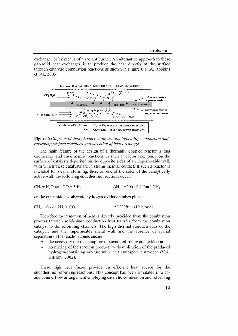
exchanger or by means of a radiant burner. An alternative approach to these gas-solid heat exchanges is to produce the heat directly at the surface through catalytic combustion reactions as shown in Figure 6 (F.A. Robbins et. Al., 2003).
Figure 6 Diagram of dual channel configuration indicating combustion and reforming surface reactions and direction of heat exchange
The main feature of the design of a thermally coupled reactor is that exothermic and endothermic reactions in such a reactor take place on the surface of catalysts deposited on the opposite sides of an impermeable wall, with which these catalysts are in strong thermal contact. If such a reactor is intended for steam reforming, then, on one of the sides of the catalytically active wall, the following endothermic reactions occur: CH4 + H2O ⇔ CO + 3 H2 ΔH = +206.16 kJ/mol CH4 on the other side, exothermic hydrogen oxidation takes place:
CH4 + O2 ⇔ 2H2 + CO2 ΔH°298= -319 kJ/mol
Therefore the remotion of heat is directly provided from the combustion process through solid-phase conduction heat transfer from the combustion catalyst to the reforming channels. The high thermal conductivities of the catalysts and the impermeable metal wall and the absence of spatial separation of the reaction zones ensure:
• the necessary thermal coupling of steam reforming and oxidation • no mixing of the reaction products without dilution of the produced
hydrogen-containing mixture with inert atmospheric nitrogen (V.A. Kirillov, 2002).
These high heat fluxes provide an efficient heat source for the
endothermic reforming reactions. This concept has been simulated in a co- and counterflow arrangement employing catalytic combustion and reforming

Chapter I
20
of CH4 (Frauhammer et al. 1999; Kolios 2002). Simulations indicate that with a properly designed reactor, the process is capable of achieving full methaneconversion in both flows; however, temperature management for catalyst durability remains a problem, particularly in the counterflow case.
I.5 Aim of the Work
The current research aimed at studying combined catalytic combustion of CH4 and catalytic steam reforming of CH4 in a plate type microstructured reactor. This study will seek to determine the stable operating conditions of the microreactor through the pursuit of the following objectives:
• Individuation of the main factors that influence behavior and performance of the catalytic plate reactor such as design parameters and operating conditions.
• Preparation and characterisation of the metallic structured catalysts in particular the optimization of the deposition method of catalytic washcoat
• Design and realization of an laboratory scale integrated plate type reactor which integrates exothermic catalytic combustion and endothermic catalytic steam reforming occurring across a shared surface in alternate channels.
• Tests to determinate a range of stable operating conditions for maximum performance reactor
The experimental setup will provide valuable temperature measurements
and exhaust analysis in order to study the effect that some inlet conditions, including fuel feed ratio, residence time (τ) and H2O/CH4 ratio for steam reforming reaction, have on the performance of the reactor.
II State of the art of microstructured catalytic
reactors
II.1 Introduction
This chapter is an introduction to the new field of microstructured reactors. The advantages and disadvantages will be briefly stated as well as the main differences between microreactors and conventional macro-scale equipment. Finally, the main features of metallic structured catalysts and the preparation method more commonly used and reported in the literature, are described.
II.2 Microstructured reactors for catalytic reactions
Hydrogen is typically produced by steam reforming of natural gas in long tubes packed with Ni catalyst in large furnaces. Usually fixed-bed catalytic reactors suffer from a number of inherent problems, pronounced axial and radial temperature gradients can exist because of limited heat transfer rate in a packed bed (Taegyu Kim, 2006) (with residence times of 1 s). They are characterized by hot spot at the reactor entrance and a cold spot in the second part of the reactor. The high temperature may damage the catalyst and the low temperature diminishes the rate of the reforming reaction leading to poor reactor performance. Thus the temperature control is crucial for the reactor performance. In addition, because of limitations in the heat transfer rate, this type of reactor typically has poor response to transients and similarly requires a prolonged time to reach working temperature from cold start-up. Furthermore the packed-bed reactors suffer of large gas pressure drop in the catalyst tube. Also, the high flame temperatures in the furnace
Chapter II
22
lead to NOx formation and a reactor system that scales down poorly to produce small or varying amounts of hydrogen. For these reasons, it is generally believed in the hydrogen and fuel cell R&D communities that a more compact, lower cost reformer would be needed for standalone hydrogen production at refueling stations (Ogden et.al 1996).
Chemical microstructured reactor (MSR) are devices containing open paths for fluids with dimensions in the millimeter range. Mostly MSR have multiple parallel channels with diameters between 10 and several hundred micrometers where the chemical reactions occur (V. Vessel, 2003). The small parallel flowpaths reduce the distance between the heat source and the heat sink: as this distance is reduced, the corresponding heat transfer by radiation and convection is strongly enhanced and also the mass transport to the catalyst surface becomes facilitated. In addition, because the catalyst is present in the system as a very thin layer covering a metallic surface, very low pressure drop - compared with the traditional granular catalyst packing - are induced in the reactor (L. Kiwi, 2005).
The main future of microstructured reactors is their high surface to volume ratio in the range of 10,000-50,000 m2/m3 compared to more traditional chemical reactors. The specific surface in conventional laboratory and production vessels is usually 100 m2/m3 and seldom exceeds 1000 m2/m3. Usually MSR are operated under laminar flow conditions. Accordingly the heat transfer coefficient is inversely proportional to the channel diameter, and their values are about 10 KW/(m2 K) being roughly one order of magnitude higher than in the traditional heat exchangers (W.Ehrfeld,1999). The high heat transfer allow to utilize the full potential of catalysts during higly endothermic or exothermic reactions and avoid hot-spots formation (G.Kolb,2004). In addition, microstructures allow fast heating and cooling of reaction mixtures in reactor system (Alepee C., 2000). The small diameters of the reactor channels ensure a short radial diffusion time leading to a narrow residence time distribution. This is advantageous for consecutive processes since high selectivity to the desired intermediate is achieved. Short residence time and narrow RTD are the main characteristics of MSR. Avoiding heat- and mass-transfer limitations is the main objective for the MSR development compared to more conventional apparatus. In addition, the small inventories of reactants and products lead to inherent safety during the reactor operation. It has been reported that the MSR run safely under conditions, which included the explosion regime (G.Veser, 2000). Small reactor dimensions facilitate the use of distributed production units at the place of consumption. This avoids the transport and storage of dangerous materials. Another aspect is the easier scale-up by multiplying the number (numbering-up) of MSR units without change of the channel geometry.
In summary, microstructured reactors are suitable for fast, highly exothermic or endothermic chemical reactions because they lead to:
Microstructured reactor
23
• process intensification • inherent reactor safety • broader reaction conditions including up-to the explosion regime • distributed production • faster process development
Most examples for MSR applications concern laboratory scale, like for
the distributed production of hydrogen for the production of electrical energy.
Different reactions have been used to illustrate the advantages of performing chemical reaction in microreactors, which are particularly suited for highly exothermic and fast reactions. The temperature control significantly reduces side reaction and prevents hot-spots formation. Higher reaction temperatures are attained leading to reduced reaction volumes and the use of lower amount of catalyst. This improves the process energy efficiency and reduces the operational cost (C. Cao, 2005).
Fast heat and mass transfer increase the process efficiency, which permits process miniaturization without sacrificing productivity.
Therefore microstructured reactor-based fuel processors are small, efficient, modular, lightweight, and potentially inexpensive.
II.2.1 Catalytic wall reactor (CWR)
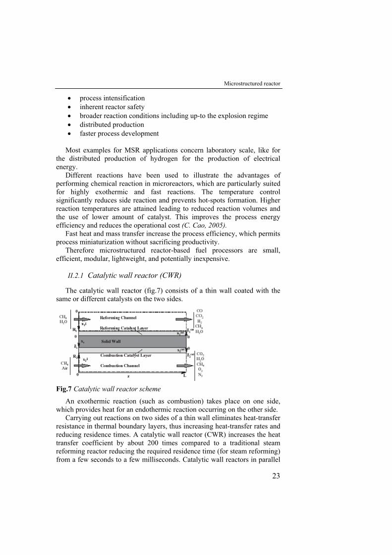
The catalytic wall reactor (fig.7) consists of a thin wall coated with the same or different catalysts on the two sides.
Fig.7 Catalytic wall reactor scheme
An exothermic reaction (such as combustion) takes place on one side, which provides heat for an endothermic reaction occurring on the other side.
Carrying out reactions on two sides of a thin wall eliminates heat-transfer resistance in thermal boundary layers, thus increasing heat-transfer rates and reducing residence times. A catalytic wall reactor (CWR) increases the heat transfer coefficient by about 200 times compared to a traditional steam reforming reactor reducing the required residence time (for steam reforming) from a few seconds to a few milliseconds. Catalytic wall reactors in parallel
Chapter II
24
plate configurations can also be scaled more easily than multitube reactors in furnaces. The main feature of the design of a thermally coupled reactor is that exothermic and endothermic reactions in such a reactor take place on the surface of catalysts deposited on the opposite sides of an impermeable wall, with which these catalysts are in strong thermal contact. If such a reactor is intended for CH4 steam reforming, then, on one of the sides of the catalytically active wall the endothermic steam reforming reactions occur, on the other side, exothermic fuel oxidation takes place. The high thermal conductivities of the catalysts and of the impermeable metal wall and the absence of spatial separation of the reaction zones ensure the necessary thermal coupling of steam reforming and oxidation without mixing of the reaction products and without dilution of the produced hydrogen-containing mixture with inert atmospheric nitrogen.
Catalytic wall reactors have been investigated for several years, initially there were problems about material stability that limited maximum temperatures to values lower than 800 °C, which are too low to steam reform hydrocarbon fuels in millisecond contact times.
Hunter and McGuire (1980) were among the first to suggest the coupling of endothermic with exothermic reaction by means of indirect heat transfer. They considered heat exchangers where catalytic combustion or other highly exothermic reaction is used as a heat source for an endothermic reaction.
Koga and Watanabe(1991) described a plate type reformer that coupled catalytic combustion and reforming, which took place in alternate channels. The catalysts filled the gaps between the plates and were not deposited on the walls, which resulted in higher heat-transfer resistance.
Igarashi et al.(1992) described a wall reactor that used a heating medium to supply heat for an endothermic reaction that occurred on walls in alternate channels, although the presence of a thermal boundary layer in the combustion channel resulted in high heat-transfer resistance.
Kaminsky, Huff, Calamur, and Spangler (1997) presented a “dual-flow chemical reactor” which employed oxidative coupling of methane on catalytically coated surfaces to provide heat for thermal hydrocarbon cracking. This particular combination of reactions allows the production of useful compounds from both sides of the reactor. Ioannides and Verykios (1997, 1998) studied another concept of integrating different reactions for synthesis gas production. The reactor consists of an open-ended non-porous ceramic tube with high thermal conductivity, whose surfaces are coated with catalytic layers. A CH4/O2 feed enters the tube and part of it combusts on its inner catalytic surface. Subsequently the reaction mixture comes in contact with the outside catalytic surface where reforming takes place. A large fraction of the heat generated on the inside wall by methane combustion is transported to the outside wall where the endothermic reforming reactions occur. A design of alternating small channels with catalyst for endothermic and exothermic reactions has been patented recently by Mulvaney and
Microstructured reactor
25
Dandekar (2000). Different flowsheet configurations, including pre-heating arrangements with catalyst-free sections for endothermic streams, are proposed to ensure a highly heat integrated process.
Venkataraman, Redenius, and Schmidt (2002) explored experimentally and theoretically ethane dehydrogenation coupled with methane catalytic combustion in a concentric tube configuration operating at about 1000°C. The system showed comparable performance to a conventional cracker at much shorter contact time (50 ms compared to 1 s).
Coupling of steam reforming and catalytic combustion in adjacent channels received attention recently due to its potential to provide compact hydrogen generation systems for fuel cells. A small reactor enables the placement of the hydrogen generation unit near the point of use. Methane is a convenient feedstock because the existing natural gas pipeline infrastructure makes it readily available and accessible at any point along the distribution chain. Availability of highly compact hydrogen generators will make possible electrical power generation by fuel cells at central stations, substations, or residences.
Branch and Tomlinson (1995) studied this process theoretically and showed that catalyst deactivation can have severe consequences on the operation and stability of the reactor. Polman, Der Kinderen, and Thuis (1999) described and tested a metal flat plate reactor that coupled catalytic combustion and methane steam reforming in alternate channelswith catalysts coated on both sides of the walls. This systems was operated successfully only below 800°C about, and the stability of catalyst and wall materials, and heat losses from the reactor, seemed to limit successful operation in these systems. They achieved experimentally 99.98% and 97% conversions of combustion and reforming reactions, respectively, in a co-current plate reactor. NOx levels were within the ppb range.
Eigenberger’s group (Frauhammer, Eigenberger, Hippel, & Arntz, 1999; Kolios, Frauhammer, & Eigenberger, 2001, 2002) studied the process both experimentally and theoretically, mainly in counter-current configuration utilising a ceramic honeycomb monolith with specially designed reactor heads. The inlets and exits of both streams were at low temperature while a high temperature zone in the middle of the reactor resulted in high conversion. It was shown that reactor performance could be affected by the presence of homogeneous reaction, ratio of heat capacities of the two streams and the degree of overlapping of the two reaction zones. The analysis of the thermal behaviour for the counter-current arrangement by one-dimensional model revealed that a temperature rise of the exothermic reaction quickly above the temperature of the endothermic one is necessary in order to avoid back-transfer of heat within the main reaction zone. Hot spots could be avoided utilising an optimal overlapping of the reaction zones, using a suitable co-current arrangement or distributing the fuel feed along the reactor. Zalc and Loffler (2002) described a plate reformer for
Chapter II
26
methane steam reforming that consisted of a single reforming channel with a combustion channel on either side. Temperatures and residence times were not discussed for most of these systems. Water-gas shift reactions to increase H2/CO ratios were not considered.
A heat exchanging tubular reactor was developed and tested by Ismagilov, Pushkarev, Podyacheva, Koryabkina, and Veringa (2001). Methane combustion and steam reforming catalysts were incorporated within metal foams attached to the external and internal surfaces of a stainless-steel metal tube. By adding hydrogen in the combustion mixture, conversion of methane in the steam reforming section was increased to ca. 65%, while maintaining a more uniform reactor temperature profile in the range 850–900°C.
Frauhammer etal., 1999; Kolios et al.( 2001, 2002) presented modelling studies of such reaction system based on a simplified one-dimensional approach studying mainly axial temperature profiles. A two-dimensional approach (Zanfir & Gavriilidis, 2001) makes the model more realistic by increasing its capability to capture the effect of parameters such as wall thickness, and channel height, and eliminates the uncertainties introduced by heat and mass transfer coefficients used in one-dimensional models.
Zanfir & Gavriilidis (2003) presented a theoretical study of methane steam reforming coupled with methane catalytic combustion in a catalytic plate reactor (CPR) based on a two-dimensional model. simulated the CPR and carried out parametric studies relatedto channel height and catalyst layer that can provide guidance for the practical implementation of such design.
A parallel plate catalytic wall reactor was built in which exothermic methane combustion on platinum and endothermic methane steam reforming on rhodium occurred on walls in alternate channels (Venkataraman K. et al., 2003). This reactor gave 95% conversion of methane to synthesis gas with a residence time of about 70 ms at a steam/methane ratio of 1/1 with a thermal efficiency of ~60%.
II.3 Metallic structured catalysts
Conventional structured catalyst supports such as foams and monoliths used for gas-phase reactions, e.g., catalytic converters and volatile organic compound destruction, are generally ceramic-based. Although the ceramic support provides the advantages of low-pressure drop and high catalyst utilization efficiency, the poor heat transfer is still a problem resulting from low thermal conductivity.
A metallic structured support, with its inherent high thermal conductivity, can be used as a substrate of catalysts and integrated for microchannel reactor applications. Thin layers of catalyst coating (typically<40 mm) on the metal substrate give much shorter transport distances than that of
Microstructured reactor
27
conventional catalysts (Y. Wang, 2005). In addition to better heat transfer, the sponge-like mechanical properties allow flexibility in sealing of catalysts in a reaction channel.
The closely matched thermal expansion between the structured metal supports and the housing reaction channels reduces the probability of structure cracking, which consequently minimizes gas channeling around the structured supports at higher reaction temperatures. The synergistically reduced resistance of mass/heat transfer in microchannel reactors and microstructured catalysts enhances the rate of the control step to match the fast reaction kinetics (C.Cao,2005).
The main difficulty is the introduction of solid catalyst into microchannel that ensure the absence of pressure drop during passage of gases.
Metallic supports with high-temperature resistance appeared, solving the durability problem but bringing another difficulty. Because the widely used washcoat (which has high specific surface area and acts as a host for noble metal catalysts) is some kind of ceramic, the coating adhesion between the metallic support and the ceramic washcoat becomes a problem because of different thermal expansion coefficients of metallic support and ceramic washcoat (S.Zhao et al.,2003). The supports are generally alloys based on the Fe-Cr-Al system, termed FeCrAlloys (Fe 73%, Cr 20%, Al 5% and Y 2%), the use of these alloys, is due to the possibility of modifying the metal surface with thermal oxidation: the process involves the migration of γ-Al2O3 to the surface with the consequent formation of a dense and adherent layer that is also a stronger bond between the metal surface and the washcoat that has to be applied in order to make the support catalytically active. This layer prevents the loss of coating due to flaking in high temperature catalytic applications, which occurs because of the different thermal expansion coefficients of the coating layer and that of the metal support. Moreover it is resistant to oxygen diffusion and protects the underlying matrix against further degradation (L. Giani et al.,2006). Therefore in the FeCrAlloy system, the thermally grown alumina layer might act not only as a barrier for oxygen, but also as an effective bond coating. This coating is indeed intrinsically adherent to the metal substrate (as it is generated on its surface through simple oxidation reactions) and might offer, simply because it is a ceramic, a suitable surface for catalyst deposition purposes.
The required properties for the catalytic layer supported are: good adherence and uniformity of the porous layer on the structure, a large specific surface area (around 200 m2/g) of deposited alumina and a controlled thickness, from 1 to 200 µm (V. Meille, 2005).
II.3.1 Preparation of washcoated structured supports
The preparation method of a ceramic catalytic layer on a metallic support is tipically a three-step method:
Chapter II
28
(1) support pretreatment; (2) primer deposition; (3) coating deposition, through which the ceramic layer and the metallic
support can adhere very well. After cleaning (water, detergent, solvent to remove grease), the
pretreatment of the metallic support, it can follow a thermal, chemical (acidic) and/or physical (abrasion) treatment.
Valentini et al.(2001) pretreated Al slabs with HCl solutions to improve superficial roughness and subsequently with HNO3 solutions to favour the formation of superficial oxides. It is well known (S. Yasaki et al.,1993) that this kind of treatment results in the formation of an alumina oxide layer which improves greatly the adherence of the deposited γ-Al2O3 layers. XRD patterns did not show the peaks of aluminium oxides, probably because the relative amount of such oxides is very small, but SEM images confirmed that small particles of aluminium oxide were formed on the surface after the treatment with acid.
About thermal treatment, some authors (S. Zhao,2003; Valentini et al.,2001) have investigated the effects of different temperatures and times on washcoated catalysts properties.The treatment conditions resulting in a optimal coating adhesion was attained through: (1) pre-oxidizing of the metallic support at 950 °C for 10 h; (2) covering the sample with primer sol and calcination at 800 °C for 3 h; (3) depositing the sample with γ-Al2O3 slurry and calcination at 900 °C for 2 h.
Ugues et al.(2004) optimize the preoxidation treatment proving that at 1200 °C the oxides had completely globular grains morphology and the best achievable adhesion properties; at 900 °C, the oxides had a weak whisker morphology and the adhesion between the oxide layer and the metal matrix was poor. However the 1200 °C thermally grown oxide showed a smooth surface not very suitable for hosting the catalyst deposit. The aim was to attain the best compromise between adhesion properties and surface “roughness”. This balance was achieved effectively through a decrease in the oxygen content of the oxidative pretreatment environment. An atmosphere poor in oxygen content should favor the formation of a porous and sharp edged oxide. They showed that the oxidation process carried out at 1200 °C for 10 min in 0.5 vol % oxygen led to the formation of the ideal oxide structure: well adherent at the metal-oxide interface and porous at its external surface.
The deposition of a primer to improve the adherence of the washcoat layer is well known in the literature (S. Yasaki, 1993). Usually a bohemite primer is prepared by dispersing 10% (w/w) of a commercial aluminium hydroxide powder in a 0.4% (w/w) HNO3 aqueous solution. After mixing for 10 min, a stable dispersion of bohemite is obtained. For the primer deposition, the supports are dipped in the bohemite dispersion, withdrawn at
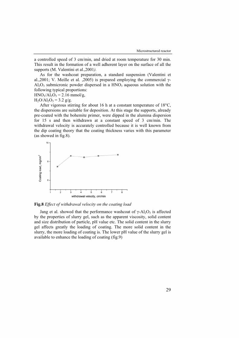
Microstructured reactor
29
a controlled speed of 3 cm/min, and dried at room temperature for 30 min. This result in the formation of a well adherent layer on the surface of all the supports (M. Valentini et al.,2001).
As for the washcoat preparation, a standard suspension (Valentini et al.,2001; V. Meille et al. ,2005) is prepared employing the commercial γ-Al2O3 submicronic powder dispersed in a HNO3 aqueous solution with the following typical proportions: HNO3/Al2O3 = 2.16 mmol/g, H2O/Al2O3 = 3.2 g/g.
After vigorous stirring for about 16 h at a constant temperature of 18°C, the dispersions are suitable for deposition. At this stage the supports, already pre-coated with the bohemite primer, were dipped in the alumina dispersion for 15 s and then withdrawn at a constant speed of 3 cm/min. The withdrawal velocity is accurately controlled because it is well known from the dip coating theory that the coating thickness varies with this parameter (as showed in fig.8).
Fig.8 Effect of withdrawal velocity on the coating load
Jang et al. showed that the performance washcoat of γ-Al2O3 is affected by the properties of slurry gel, such as the apparent viscosity, solid content and size distribution of particle, pH value etc. The solid content in the slurry gel affects greatly the loading of coating. The more solid content in the slurry, the more loading of coating is. The lower pH value of the slurry gel is available to enhance the loading of coating (fig.9)
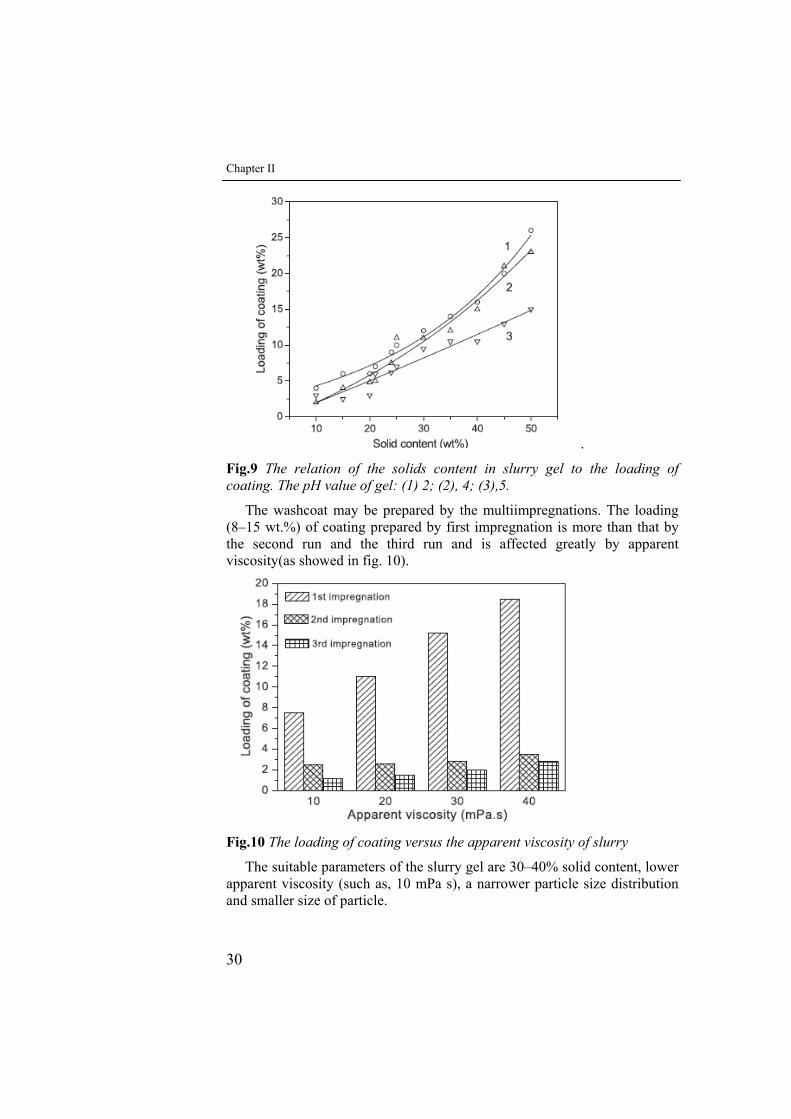
Chapter II
30
.
Fig.9 The relation of the solids content in slurry gel to the loading of coating. The pH value of gel: (1) 2; (2), 4; (3),5.
The washcoat may be prepared by the multiimpregnations. The loading (8–15 wt.%) of coating prepared by first impregnation is more than that by the second run and the third run and is affected greatly by apparent viscosity(as showed in fig. 10).
Fig.10 The loading of coating versus the apparent viscosity of slurry
The suitable parameters of the slurry gel are 30–40% solid content, lower apparent viscosity (such as, 10 mPa s), a narrower particle size distribution and smaller size of particle.
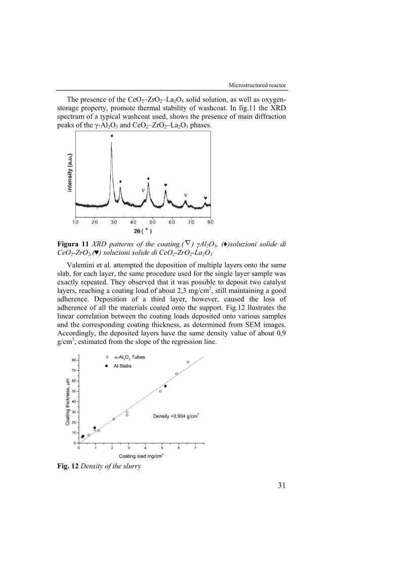
Microstructured reactor
31
The presence of the CeO2–ZrO2–La2O3 solid solution, as well as oxygen-storage property, promote thermal stability of washcoat. In fig.11 the XRD spectrum of a typical washcoat used, shows the presence of main diffraction peaks of the γ-Al2O3 and CeO2–ZrO2–La2O3 phases.
Figura 11 XRD patterns of the coating.( ) γAl2O3, (♦)soluzioni solide di CeO2-ZrO2,(♥) soluzioni solide di CeO2-ZrO2-La2O3
Valentini et al. attempted the deposition of multiple layers onto the same slab, for each layer, the same procedure used for the single layer sample was exactly repeated. They observed that it was possible to deposit two catalyst layers, reaching a coating load of about 2,3 mg/cm2, still maintaining a good adherence. Deposition of a third layer, however, caused the loss of adherence of all the materials coated onto the support. Fig.12 llustrates the linear correlation between the coating loads deposited onto various samples and the corresponding coating thickness, as determined from SEM images. Accordingly, the deposited layers have the same density value of about 0,9 g/cm3, estimated from the slope of the regression line.
Fig. 12 Density of the slurry

III Experimental setup
III.1 Introduction
The current study explores the possibility to produce H2 employing a reactor configuration made of parallel flat plates resulting in alternate channels for CH4 steam reforming and CH4 catalytic combustion. In this chapter initially the set-up of designed catalytic plate reactor and of the respective experimental apparatus is described.
Moreover the start-up phase, that is a key feature for a compact fuel processor, is explained. Finally, this chapter illustrates how the experimental tests will be carried out and how the operating parameters (namely reforming fuel conversion, hydrogen yield, thermal efficiency) will be determined from experimental measurements. Numerous tests will be performed to find stable operating conditions and optimal H2 production, the results would provide the basis for assessing the operability of a given catalyst combination in a larger reactor and a means for validating a flat-plate reactor numerical model.
III.2 Description of the catalytic plate reactor
Fig. 13 shows a schematic configuration of the reactor. The reactor is three-channel system with two exothermic channels and one endothermic channel: two thin flat foils with supported washcoat coatings on opposite sides separate the catalytic combustion channels from the reforming one.
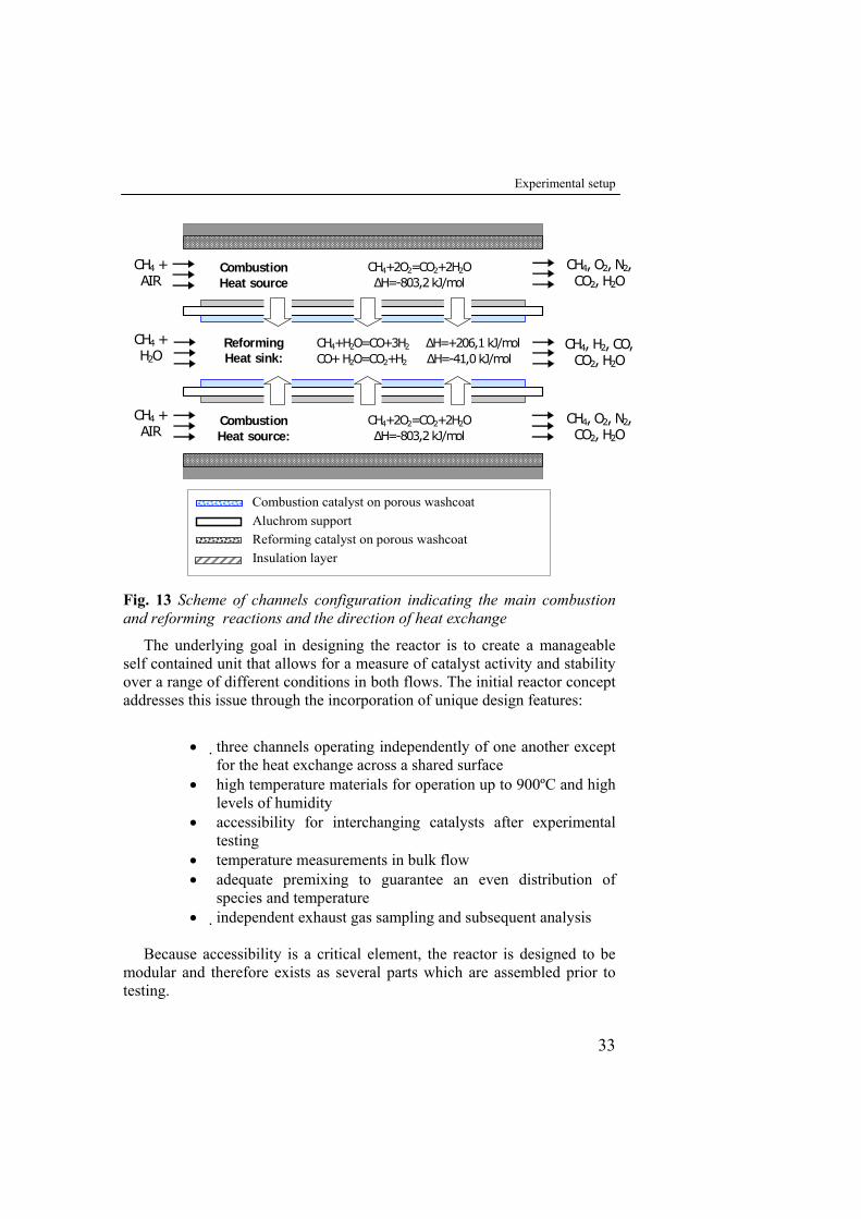
Experimental setup
33
CH4 + H2O
CH4 + AIR
CH4 + AIR
Reforming Heat sink:
CH4+2O2=CO2+2H2O ΔH=-803,2 kJ/mol
Combustion Heat source
CH4+H2O=CO+3H2 ΔH=+206,1 kJ/mol CO+ H2O=CO2+H2 ΔH=-41,0 kJ/mol
CH4+2O2=CO2+2H2O ΔH=-803,2 kJ/mol
Combustion Heat source:
CH4, O2, N2, CO2, H2O
CH4, O2, N2, CO2, H2O
CH4, H2, CO, CO2, H2O
Combustion catalyst on porous washcoat Aluchrom support Reforming catalyst on porous washcoat Insulation layer
Fig. 13 Scheme of channels configuration indicating the main combustion and reforming reactions and the direction of heat exchange
The underlying goal in designing the reactor is to create a manageable self contained unit that allows for a measure of catalyst activity and stability over a range of different conditions in both flows. The initial reactor concept addresses this issue through the incorporation of unique design features:
• three channels operating independently of one another except
for the heat exchange across a shared surface • high temperature materials for operation up to 900ºC and high
levels of humidity • accessibility for interchanging catalysts after experimental
testing • temperature measurements in bulk flow • adequate premixing to guarantee an even distribution of
species and temperature • independent exhaust gas sampling and subsequent analysis
Because accessibility is a critical element, the reactor is designed to be
modular and therefore exists as several parts which are assembled prior to testing.
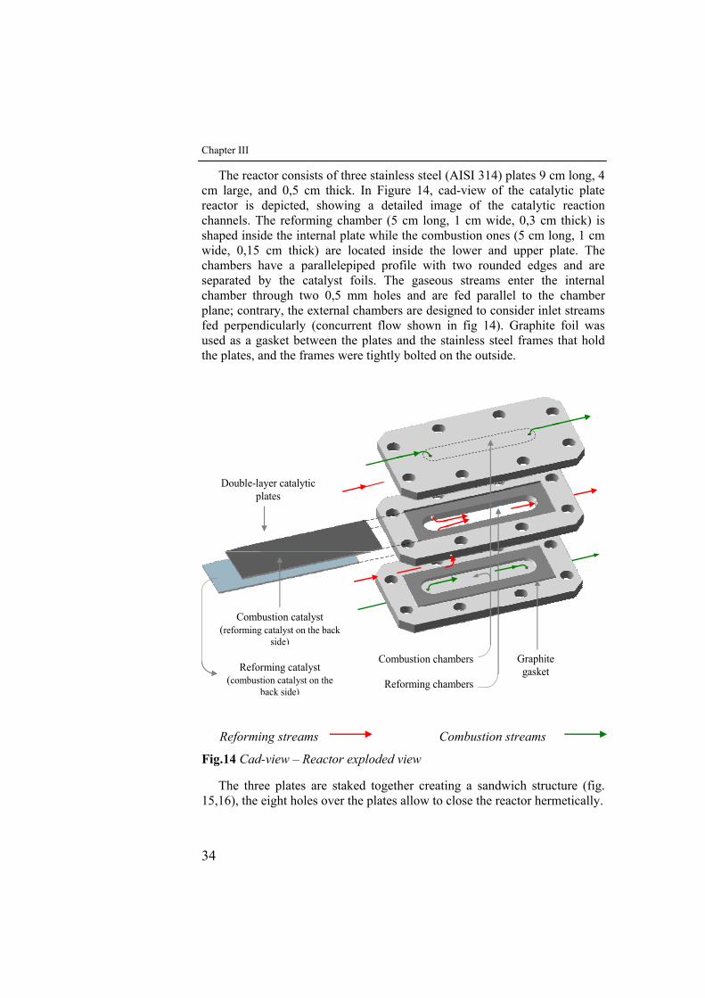
Chapter III
34
The reactor consists of three stainless steel (AISI 314) plates 9 cm long, 4 cm large, and 0,5 cm thick. In Figure 14, cad-view of the catalytic plate reactor is depicted, showing a detailed image of the catalytic reaction channels. The reforming chamber (5 cm long, 1 cm wide, 0,3 cm thick) is shaped inside the internal plate while the combustion ones (5 cm long, 1 cm wide, 0,15 cm thick) are located inside the lower and upper plate. The chambers have a parallelepiped profile with two rounded edges and are separated by the catalyst foils. The gaseous streams enter the internal chamber through two 0,5 mm holes and are fed parallel to the chamber plane; contrary, the external chambers are designed to consider inlet streams fed perpendicularly (concurrent flow shown in fig 14). Graphite foil was used as a gasket between the plates and the stainless steel frames that hold the plates, and the frames were tightly bolted on the outside.
Reforming catalyst (combustion catalyst on the
back side)
Combustion chambers
Reforming chambers
Graphite gasket
Double-layer catalytic plates
Combustion catalyst (reforming catalyst on the back
side)
Reforming streams Combustion streams
Fig.14 Cad-view – Reactor exploded view
The three plates are staked together creating a sandwich structure (fig. 15,16), the eight holes over the plates allow to close the reactor hermetically.

Experimental setup
35
Fig.15 Cad-view - Assembled Reactor
Fig.16 Reactor image
Methane catalytic combustion takes place in the two outer channels and methane steam reforming takes place in the inner channel. The washcoated aluchrom supports separate the internal channel by the outer channels, so ensuring impermeability between oxidation and reforming channels. The combustion channel formed is bordered on the external side by the non-catalytic reactor wall and on the internal side by catalytic separating plate.
The other combustion channel is the mirror image of the first one. The reforming channel is bordered on both sides by catalytic separating plates.
The portion of the support in the reaction zone is coated on one side with the reforming catalyst and on the other side with that for combustion catalyst.
Experiments with N2 and air flows were performed to verify the tightness between the reactor channels.

Chapter III
36
III.3 Experimental apparatus
The lay-out of the experimental plant, shown schematically in Fig.17, consists of a feed section for methane steam reforming and total oxidation, reaction section and analysis section. As still picture of lay-out of the experimental plant is reported in fig.18.
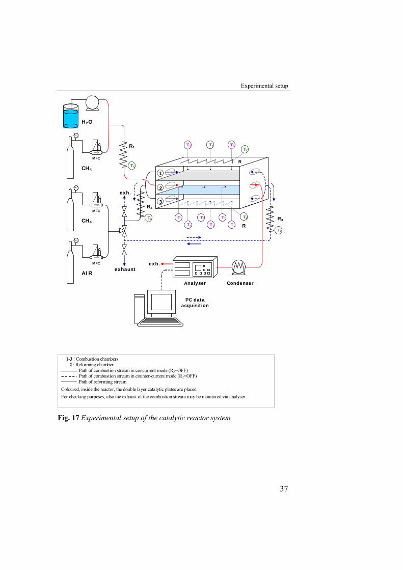
Experimental setup
37
1-3 : Combustion chambers 2 : Reforming chamber Path of combustion stream in concurrent mode (R3=OFF) Path of combustion stream in counter-current mode (R2=OFF) Path of reforming stream Coloured, inside the reactor, the double layer catalytic plates are placed For checking purposes, also the exhaust of the combustion stream may be monitored via analyser
MFC
AIR
CH4
CH4
H2O
MFC
MFC
R1
TC
1
3
2
R3
TC
R
TC
TT TT TT
TT TT TT
TT TT TT TC
exh.
exhaust
R2
Analyser Condenser
exh.
PC data acquisition
Fig. 27: Experimental setup of the catalytic reactor system
TC
R
Fig. 17 Experimental setup of the catalytic reactor system
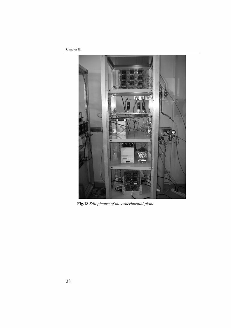
Chapter III
38
Fig.18 Still picture of the experimental plant
Experimental setup
39
III.3.1 Feed section
The reactants CH4 and air for the combustion chambers and CH4 and water vapour for the reforming one were fed through stainless steel tubes (1/8”) and adequately premixed, to guarantee an even distribution of species, before entering the reactor.
After mixing, the combustion flow is preheated using electric heaters(R2 or R3, fig.17) and split into two inlets, through a T-junction connection, equally feeding the upper and the lower combustion chamber. After mixing the methane and water vapor flow is preheated using an electric heater (R1) and, then, split into two opposite inlets of the reforming chamber. Limit operating temperature of the heating element is about 700°C. The preheating temperature of feeding gas and of the reactor is controlled by temperature controllers (TLK 43 type) collected in a box supported on the bottom shelf of the plant (fig.18). Thermocouples used for the temperature control are inserted in tubes welded to the respective resistances that havo to control (for preheating feed gas streams and for preheating the reactor).
The flow rates of all of the gases in the experiment are controlled by Brooks SL5800 mass flow controllers (fig. 20), while the feeding water flow rate is regulated by a peristaltic pump “Gilson”. (fig. 19).
The working principle of the MFC is heat transport: the temperature difference in a capillary, where a part of the gas is split, it is measured. This temperature difference is proportional to the amount of heat adsorbed by the mass gas for the equation: ΔT = K • Cp • Φm where:
ΔT = temperature difference. Cp = specific heat of the gas. K = dimensional constant. Φm = mass flow
The instrument’s temperature detector produces an electrical signal from
0 to 5 V (c.c.); this signal is sent to the control unit (MFC C.U.) which converts the signal in volumetric flow. This control unit allows the mass flow of the gases to be regulated.
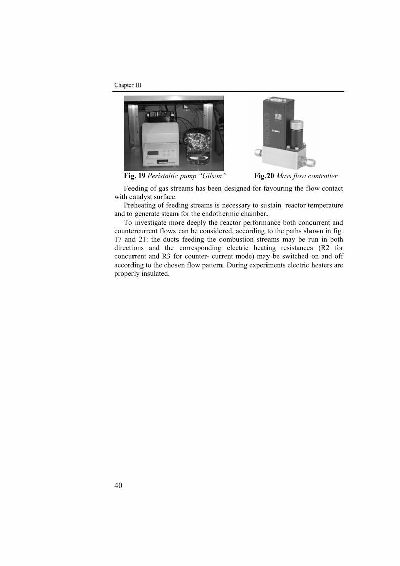
Chapter III
40
Fig. 19 Peristaltic pump “Gilson” Fig.20 Mass flow controller
Feeding of gas streams has been designed for favouring the flow contact with catalyst surface.
Preheating of feeding streams is necessary to sustain reactor temperature and to generate steam for the endothermic chamber.
To investigate more deeply the reactor performance both concurrent and countercurrent flows can be considered, according to the paths shown in fig. 17 and 21: the ducts feeding the combustion streams may be run in both directions and the corresponding electric heating resistances (R2 for concurrent and R3 for counter- current mode) may be switched on and off according to the chosen flow pattern. During experiments electric heaters are properly insulated.
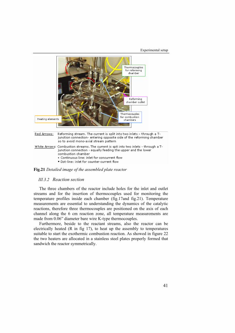
Experimental setup
41
Fig.21 Detailed image of the assembled plate reactor
III.3.2 Reaction section
The three chambers of the reactor include holes for the inlet and outlet streams and for the insertion of thermocouples used for monitoring the temperature profiles inside each chamber (fig.17and fig.21). Temperature measurements are essential to understanding the dynamics of the catalytic reactions, therefore three thermocouples are positioned on the axis of each channel along the 6 cm reaction zone, all temperature measurements are made from 0.06” diameter bare wire K-type thermocouples.
Furthermore, beside to the reactant streams, also the reactor can be electrically heated (R in fig 17), to heat up the assembly to temperatures suitable to start the exothermic combustion reaction. As showed in figure 22 the two heaters are allocated in a stainless steel plates properly formed that sandwich the reactor symmetrically.
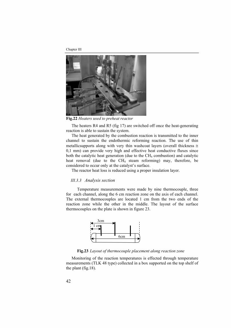
Chapter III
42
6cm
1 cm
Fig.22 Heaters used to preheat reactor
The heaters R4 and R5 (fig 17) are switched off once the heat-generating reaction is able to sustain the system.
The heat generated by the combustion reaction is transmitted to the inner channel to sustain the endothermic reforming reaction. The use of thin metallicsupports along with very thin washcoat layers (overall thickness ≅ 0,1 mm) can provide very high and effective heat conductive fluxes since both the catalytic heat generation (due to the CH4 combustion) and catalytic heat removal (due to the CH4 steam reforming) may, therefore, be considered to occur only at the catalyst’s surface.
The reactor heat loss is reduced using a proper insulation layer.
III.3.3 Analysis section
Temperature measurements were made by nine thermocouple, three for each channel, along the 6 cm reaction zone on the axis of each channel. The external thermocouples are located 1 cm from the two ends of the reaction zone while the other in the middle. The layout of the surface thermocouples on the plate is shown in figure 23.
Fig.23 Layout of thermocouple placement along reaction zone
Monitoring of the reaction temperatures is effected through temperature measurements (TLK 48 type) collected in a box supported on the top shelf of the plant (fig.18).
3cm
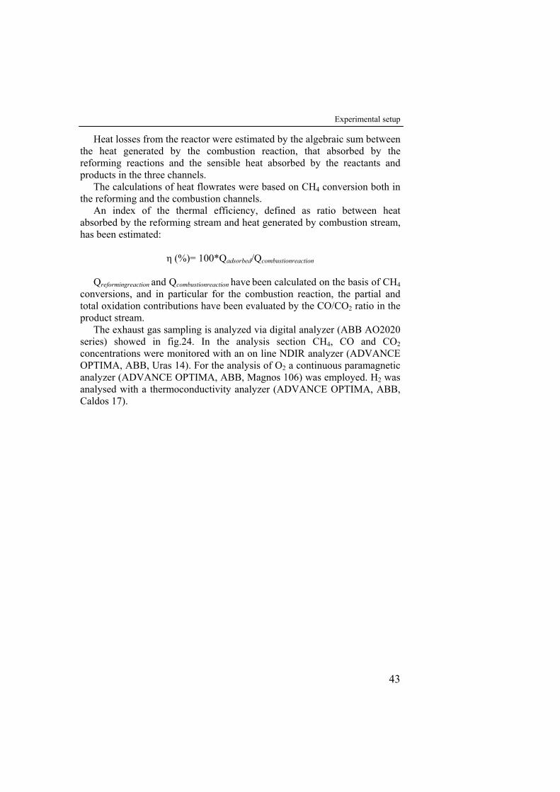
Experimental setup
43
Heat losses from the reactor were estimated by the algebraic sum between the heat generated by the combustion reaction, that absorbed by the reforming reactions and the sensible heat absorbed by the reactants and products in the three channels.
The calculations of heat flowrates were based on CH4 conversion both in the reforming and the combustion channels.
An index of the thermal efficiency, defined as ratio between heat absorbed by the reforming stream and heat generated by combustion stream, has been estimated:
η (%)= 100*Qadsorbed/Qcombustionreaction
Qreformingreaction and Qcombustionreaction have been calculated on the basis of CH4 conversions, and in particular for the combustion reaction, the partial and total oxidation contributions have been evaluated by the CO/CO2 ratio in the product stream.
The exhaust gas sampling is analyzed via digital analyzer (ABB AO2020 series) showed in fig.24. In the analysis section CH4, CO and CO2 concentrations were monitored with an on line NDIR analyzer (ADVANCE OPTIMA, ABB, Uras 14). For the analysis of O2 a continuous paramagnetic analyzer (ADVANCE OPTIMA, ABB, Magnos 106) was employed. H2 was analysed with a thermoconductivity analyzer (ADVANCE OPTIMA, ABB, Caldos 17).
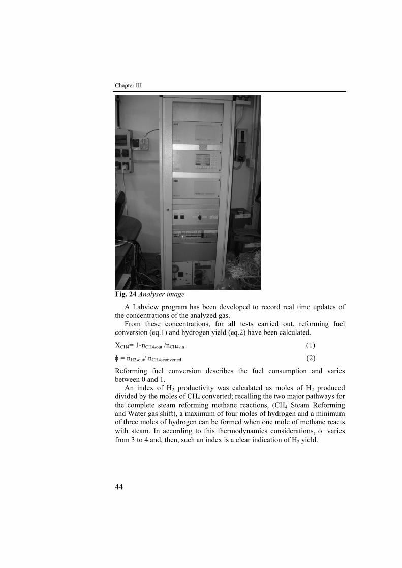
Chapter III
44
Fig. 24 Analyser image
A Labview program has been developed to record real time updates of the concentrations of the analyzed gas.
From these concentrations, for all tests carried out, reforming fuel conversion (eq.1) and hydrogen yield (eq.2) have been calculated.
XCH4= 1-nCH4,out /nCH4,in (1)
φ = nH2,out/ nCH4,converted (2)
Reforming fuel conversion describes the fuel consumption and varies between 0 and 1.
An index of H2 productivity was calculated as moles of H2 produced divided by the moles of CH4 converted; recalling the two major pathways for the complete steam reforming methane reactions, (CH4 Steam Reforming and Water gas shift), a maximum of four moles of hydrogen and a minimum of three moles of hydrogen can be formed when one mole of methane reacts with steam. In according to this thermodynamics considerations, φ varies from 3 to 4 and, then, such an index is a clear indication of H2 yield.
Experimental setup
45
III.4 Startup
Before starting the exothermic reaction, the reactor was previously heated until to 570°C via the two resistances R4 (fig.17). In figure 22 a still picture of one such resistances is reported. The goal of this phase is to raise the temperature of the catalytic support and of all system in order to reach the conditions for which the system is thermally self sustained . Then, the methane and air flow was fed to the reactor at 500°C and the flow rate progressively increased until 6,67 mol/h. In this condition a suitable ignition of the catalytic combustion reaction in both channels was obtained and the reaction on the catalyst surface was able to sustain itself. Then, water and methane flows to the endothermic channel were fed at 500°C.
III.5 Testing conditions
In order to determine the operability of the reactor and the best operating conditions for stable performance of catalytic combustion with simultaneous heat transfer to the steam reforming channel, preliminary tests where only combustion took place were performed. In this case a 50 l/h nitrogen flow rate in the inner channel at 100 °C was fed. The influence of the variation of the CH4/O2 feeding ratio and of the mean gas residence time (τ) in the channel was investigated. Three different CH4/O2 feeding ratios were considered:
• 1/2 (stoichiometric with respect to methane total oxidation) • 1/2.7 (rich-O2 stream) • 1/1.68 (lean-O2 stream)
The mean gas residence time (τ) of combustion gas was varied between
165-11 ms. After the cited prelimirary tests, reforming tests were performed in order to find the better operating conditions to obtain high methane conversion and high H2 yield in the reforming channel. This was done by keeping constant the operating feed ratio and temperature conditions at the values found more suitable in the preliminary combustion ,tests . As stated above in all the tests, temperature profiles in the outer and in the inner channels were monitored.
The investigation was focused on the influence of:
• Steam content. For a given methane flow rate (QCH4=6 l/h) in the endothermic channel the H2O/CH4 ratio was varied from 1.5 to 11.3 ;
• Mean gas residence time (τ). For a given H2O/CH4 molar ratio (equal to 3) QCH4 was varied from 6 l/h (τ about 80 ms) to 26
l/h (τ about 19 ms) .
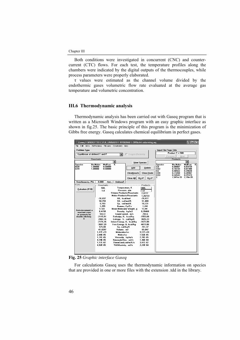
Chapter III
46
Both conditions were investigated in concurrent (CNC) and counter-current (CTC) flows. For each test, the temperature profiles along the chambers were indicated by the digital outputs of the thermocouples, while process parameters were properly elaborated.
τ values were estimated as the channel volume divided by the endothermic gases volumetric flow rate evaluated at the average gas temperature and volumetric concentration.
III.6 Thermodynamic analysis
Thermodynamic analysis has been carried out with Gaseq program that is written as a Microsoft Windows program with an easy graphic interface as shown in fig.25. The basic principle of this program is the minimization of Gibbs free energy. Gaseq calculates chemical equilibrium in perfect gases.
Fig. 25 Graphic interface Gaseq
For calculations Gaseq uses the thermodynamic information on species that are provided in one or more files with the extension .tdd in the library.
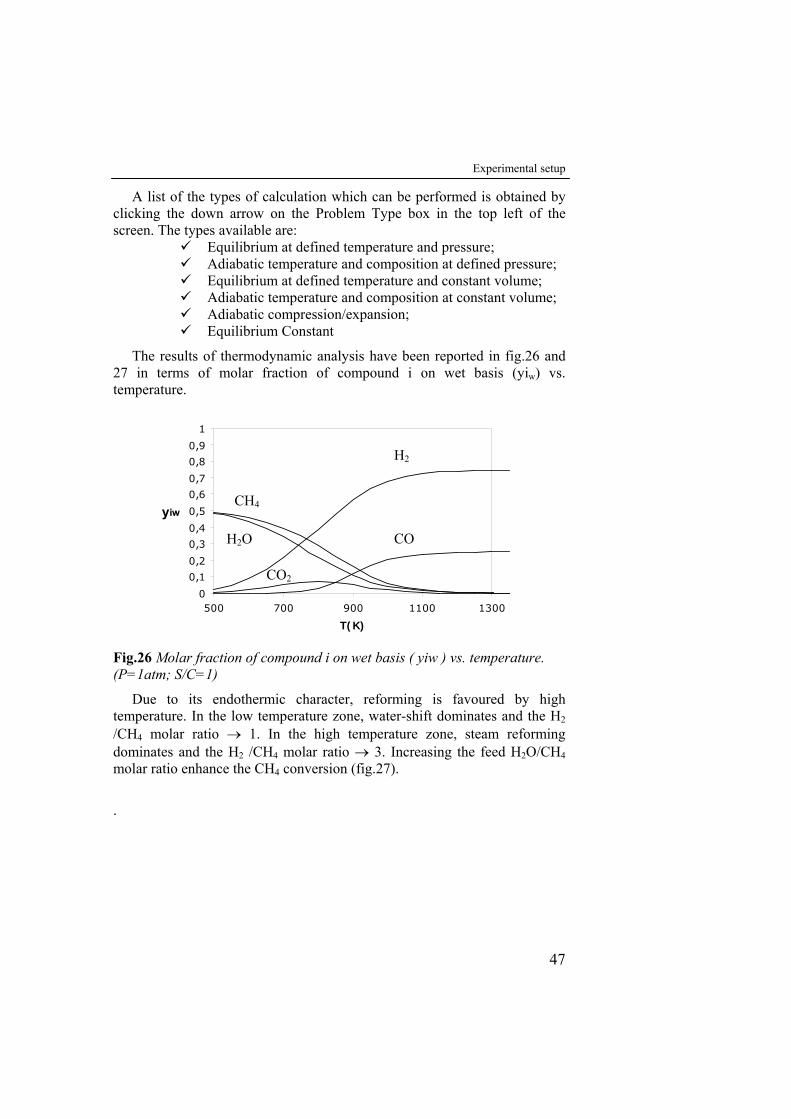
Experimental setup
47
A list of the types of calculation which can be performed is obtained by clicking the down arrow on the Problem Type box in the top left of the screen. The types available are:
Equilibrium at defined temperature and pressure; Adiabatic temperature and composition at defined pressure; Equilibrium at defined temperature and constant volume; Adiabatic temperature and composition at constant volume; Adiabatic compression/expansion; Equilibrium Constant
The results of thermodynamic analysis have been reported in fig.26 and 27 in terms of molar fraction of compound i on wet basis (yiw) vs. temperature.
0
0,1
0,2
0,3
0,4
0,5
0,6
0,7
0,8
0,9
1
500 700 900 1100 1300
T(K)
yiw
Fig.26 Molar fraction of compound i on wet basis ( yiw ) vs. temperature. (P=1atm; S/C=1)
Due to its endothermic character, reforming is favoured by high temperature. In the low temperature zone, water-shift dominates and the H2 /CH4 molar ratio → 1. In the high temperature zone, steam reforming dominates and the H2 /CH4 molar ratio → 3. Increasing the feed H2O/CH4 molar ratio enhance the CH4 conversion (fig.27).
.
CO2
H2
CO H2O
CH4
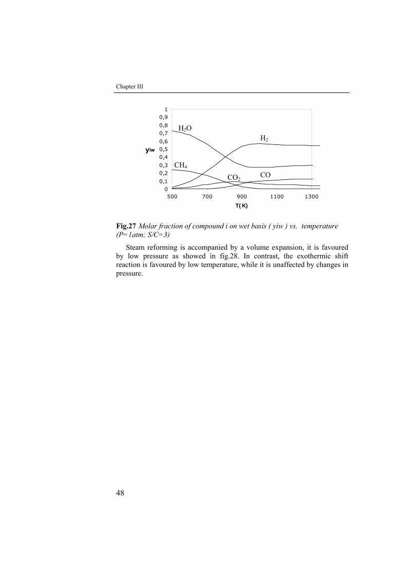
Chapter III
48
00,1
0,20,3
0,40,50,6
0,70,8
0,91
500 700 900 1100 1300
T(K)
yiw
Fig.27 Molar fraction of compound i on wet basis ( yiw ) vs. temperature (P=1atm; S/C=3)
Steam reforming is accompanied by a volume expansion, it is favoured by low pressure as showed in fig.28. In contrast, the exothermic shift reaction is favoured by low temperature, while it is unaffected by changes in pressure.
CO
H2O
CH4
H2
CO2
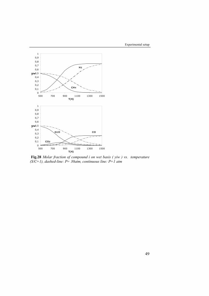
Experimental setup
49
0
0,1
0,2
0,3
0,4
0,5
0,6
0,7
0,8
0,9
1
500 700 900 1100 1300 1500T(K)
yiw
H2
CH4
0
0,1
0,2
0,3
0,4
0,5
0,6
0,7
0,8
0,9
1
500 700 900 1100 1300 1500T(K)
yiw
COH2O
CO2
Fig.28 Molar fraction of compound i on wet basis ( yiw ) vs. temperature (S/C=1), dashed-line: P= 30atm, continuous line: P=1 atm
IV Experimental Results: Structured catalysts preparation
IV.1 Introduction
This chapter presents the comparison between the characteristics of two structured metallic catalysts differing each other for the method of deposition of the catalytic washcoat on the metallic plates. Such structured metallic catalysts were preparared to be employed in the microstructured reactor, described in the chapter III, for experimental laboratory tests. In particular, brush-coating and spry-coating techniques were used and catalytic slab features compared. For their low-temperature activity towards CH4 and relatively low cost/effectiveness ratio, Pt and Ni-based supported catalysts were prepared and used to carry out catalytic combustion and steam reforming reactions, respectively.
IV.2 Material
In this study Aluchrom slabs (70% Fe, 25%Cr, 5% Al), supplied by ECOCAT s.r.l., were used as structured metallic supports. The structured catalysts were prepared using:
• commercial catalytic washcoat (38,5 wt. % solid content) supplied by ECOCAT s.r.l.,
• Ni(NO3)2·6H2O, supplied by Carlo Erba Reagenti, as active specie precursor promoting the steam reforming reaction,
• PtCl4, supplied by Carlo Erba Reagenti, as active specie precursor promoting the catalytic combustion reaction.
Structured catalysts preparation
51
IV.3 Pretreatment of metallic support
The 500 μm thick aluchrom slabs, cut with a rectangular shape (7cm x 2cm) to be lodged in the reactor slots,were pretreated before washcoating procedure. After cleaning with acetone to remove the superficial impurities, oxidative pretreatments for the segregation of an Al2O3 layer on the metallic surface, were carried out in two different ways:
• at 950°C for 2,5 h in a laboratory furnace with air flux circulating in the chamber, realised using a air compressor, to assicure an more uniform superficial Al2O3 layer (S.Zao et al.,). • at 1200 °C for 10 min in 0.5 vol % O2 in N2 atmosphere realised in a suitable laboratory furnace (Ugues2004).
Alternatively, the metallic supports were pretreated before with a 37
wt.% HCl solution at room temperature for 5 min and after with 65 wt.% HNO3 solution at 100°C for 30 min.
IV.4 Preparation of catalytic washcoat
A 5% (w/w) Ni over original washcoat catalyst for steam reforming reaction, and a 3% (w/w) Pt over original washcoat for catalytic combustion reaction were prepared using the same procedure. The mass of active specie precursor was properly calculated and weighted and, then, dissolved in H2O. The aqueous solution was added to the original washcoat, previously weighted and put in a becker. The obtained slurry was stirred on an hotplate at 120°C until it reached the initial solid concentration.
The 5% (w/w) Ni/washcoat catalyst and 3% (w/w) Pt/washcoat catalyst showed a typical green colour due to Ni presence and a typical yellow color due Pt presence, respectively.
IV.5 Preparation of structured catalysts
As said above, brush-coating (fig. 29) and spry-coating (fig.30) procedures were used and compared.
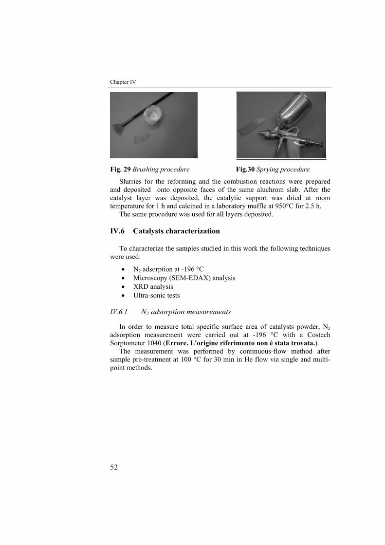
Chapter IV
52
Fig. 29 Brushing procedure Fig.30 Sprying procedure
Slurries for the reforming and the combustion reactions were prepared and deposited onto opposite faces of the same aluchrom slab. After the catalyst layer was deposited, the catalytic support was dried at room temperature for 1 h and calcined in a laboratory muffle at 950°C for 2.5 h.
The same procedure was used for all layers deposited.
IV.6 Catalysts characterization
To characterize the samples studied in this work the following techniques were used:
• N2 adsorption at -196 °C • Microscopy (SEM-EDAX) analysis • XRD analysis • Ultra-sonic tests
IV.6.1 N2 adsorption measurements
In order to measure total specific surface area of catalysts powder, N2 adsorption measurement were carried out at -196 °C with a Costech Sorptometer 1040 (Errore. L'origine riferimento non è stata trovata.).
The measurement was performed by continuous-flow method after sample pre-treatment at 100 °C for 30 min in He flow via single and multi-point methods.
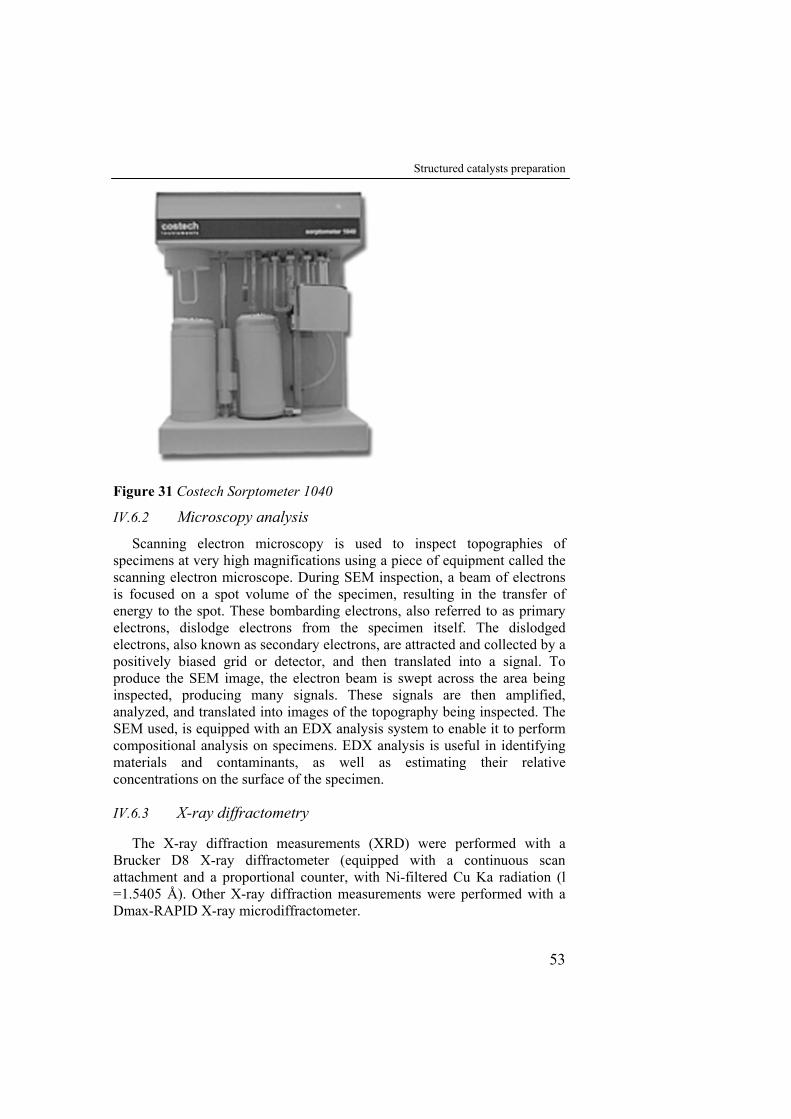
Structured catalysts preparation
53
Figure 31 Costech Sorptometer 1040
IV.6.2 Microscopy analysis
Scanning electron microscopy is used to inspect topographies of specimens at very high magnifications using a piece of equipment called the scanning electron microscope. During SEM inspection, a beam of electrons is focused on a spot volume of the specimen, resulting in the transfer of energy to the spot. These bombarding electrons, also referred to as primary electrons, dislodge electrons from the specimen itself. The dislodged electrons, also known as secondary electrons, are attracted and collected by a positively biased grid or detector, and then translated into a signal. To produce the SEM image, the electron beam is swept across the area being inspected, producing many signals. These signals are then amplified, analyzed, and translated into images of the topography being inspected. The SEM used, is equipped with an EDX analysis system to enable it to perform compositional analysis on specimens. EDX analysis is useful in identifying materials and contaminants, as well as estimating their relative concentrations on the surface of the specimen.
IV.6.3 X-ray diffractometry
The X-ray diffraction measurements (XRD) were performed with a Brucker D8 X-ray diffractometer (equipped with a continuous scan attachment and a proportional counter, with Ni-filtered Cu Ka radiation (l =1.5405 Å). Other X-ray diffraction measurements were performed with a Dmax-RAPID X-ray microdiffractometer.
Chapter IV
54
IV.6.4 Ultrasonic tests Ultrasonic tests were performed with a CP 104 Ultrasonic cleaner of
CEIA S.p.A. to test the resistance of the catalyst layer deposited on the slabs to mechanical vibrations. Different thermal expansion coefficients of the aluchrom support and γ-Al2O3 washcoat could give place to decrease of the adhesion between the washcoat and the support. Therefore, vibration tests allowed for an evaluation of the adhesion properties of metallic supports oxided in different conditions.
IV.7 Results and discussion
In the experiments carried out, the effect of the of brush and spry-coating deposition techniques was investigated and compared with respect to the better properties that washcoat layers showed
IV.7.1 Powder catalysts XRD analysis
X-ray spectra of the original washcoat, of that loaded with 5 wt% Ni and that loaded with 3 wt% Pt after calcination, are shown in fig.32.
-20
0
20
40
60
80
100
25 30 35 40 45 50 55 60 65 70 75 802 teta
Inte
nsity
5%Ni/washcoat
washcoatoriginario
3%Pt/washcoatNiO
Pt
γ-Al2O3
CeO2 - ZrO2 - La2O3 solid CeO2 - ZrO2 solid
l ti
Figure 32 XRD patterns of the original washcoat, 5%Ni washcoat and 3%Pt washcoat
The diffraction peaks of the γ-Al2O3 and CeO2–ZrO2–La2O3 phases are very evident. The peaks of α-Al2O3 and θ-Al2O3 in washcoat has not been detected.
Pseudoboehmite has translated into γ-Al2O3 at the calcination temperature (950°C). The diffraction peaks of γ-Al2O3 at 2θ=45,6°; 49,8°; 69° were
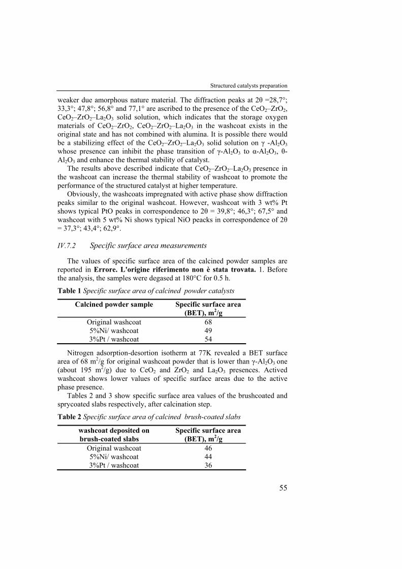
Structured catalysts preparation
55
weaker due amorphous nature material. The diffraction peaks at 2θ =28,7°; 33,3°; 47,8°; 56,8° and 77,1° are ascribed to the presence of the CeO2–ZrO2, CeO2–ZrO2–La2O3 solid solution, which indicates that the storage oxygen materials of CeO2–ZrO2, CeO2–ZrO2–La2O3 in the washcoat exists in the original state and has not combined with alumina. It is possible there would be a stabilizing effect of the CeO2–ZrO2–La2O3 solid solution on γ -Al2O3 whose presence can inhibit the phase transition of γ-Al2O3 to α-Al2O3, θ-Al2O3 and enhance the thermal stability of catalyst.
The results above described indicate that CeO2–ZrO2–La2O3 presence in the washcoat can increase the thermal stability of washcoat to promote the performance of the structured catalyst at higher temperature.
Obviously, the washcoats impregnated with active phase show diffraction peaks similar to the original washcoat. However, washcoat with 3 wt% Pt shows typical PtO peaks in correspondence to 2θ = 39,8°; 46,3°; 67,5° and washcoat with 5 wt% Ni shows typical NiO peacks in correspondence of 2θ = 37,3°; 43,4°; 62,9°.
IV.7.2 Specific surface area measurements
The values of specific surface area of the calcined powder samples are reported in Errore. L'origine riferimento non è stata trovata. 1. Before the analysis, the samples were degased at 180°C for 0.5 h.
Table 1 Specific surface area of calcined powder catalysts
Calcined powder sample Specific surface area (BET), m2/g
Original washcoat 68 5%Ni/ washcoat 49 3%Pt / washcoat 54
Nitrogen adsorption-desortion isotherm at 77K revealed a BET surface area of 68 m2/g for original washcoat powder that is lower than γ-Al2O3 one (about 195 m2/g) due to CeO2 and ZrO2 and La2O3 presences. Actived washcoat shows lower values of specific surface areas due to the active phase presence.
Tables 2 and 3 show specific surface area values of the brushcoated and sprycoated slabs respectively, after calcination step.
Table 2 Specific surface area of calcined brush-coated slabs
washcoat deposited on brush-coated slabs
Specific surface area (BET), m2/g
Original washcoat 46 5%Ni/ washcoat 44 3%Pt / washcoat 36
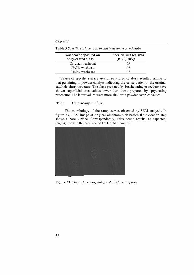
Chapter IV
56
Table 3 Specific surface area of calcined spry-coated slabs
washcoat deposited on spry-coated slabs
Specific surface area (BET), m2/g
Original washcoat 63 5%Ni/ washcoat 49 3%Pt / washcoat 47
Values of specific surface area of structured catalysts resulted similar to that pertaining to powder catalyst indicating the conservation of the original catalytic slurry structure. The slabs prepared by brushcoating procedure have shown superficial area values lower than those prepared by sprycoating procedure. The latter values were more similar to powder samples values.
IV.7.3 Microscopy analysis
The morphology of the samples was observed by SEM analysis. In figure 33, SEM image of original aluchrom slab before the oxidation step shows a bare surface. Correspondently, Edax sound results, as expected, (fig.34) showed the presence of Fe, Cr, Al elements.
Figure 33. The surface morphology of aluchrom support
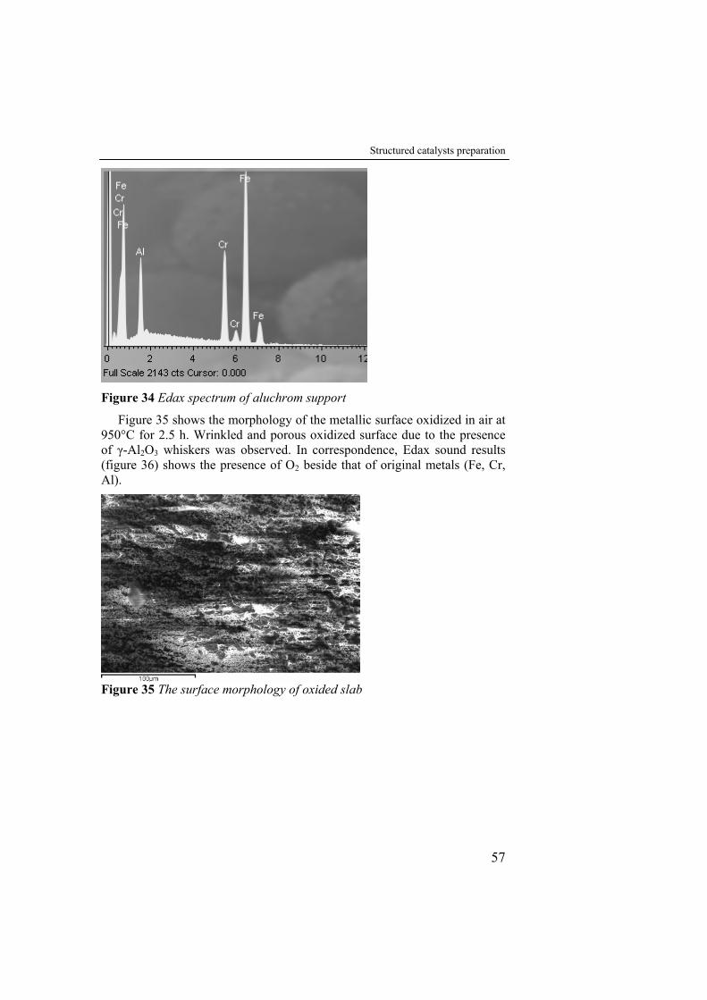
Structured catalysts preparation
57
Figure 34 Edax spectrum of aluchrom support
Figure 35 shows the morphology of the metallic surface oxidized in air at 950°C for 2.5 h. Wrinkled and porous oxidized surface due to the presence of γ-Al2O3 whiskers was observed. In correspondence, Edax sound results (figure 36) shows the presence of O2 beside that of original metals (Fe, Cr, Al).
Figure 35 The surface morphology of oxided slab
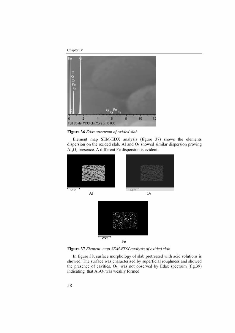
Chapter IV
58
Figure 36 Edax spectrum of oxided slab
Element map SEM-EDX analysis (figure 37) shows the elements dispersion on the oxided slab. Al and O2 showed similar dispersion proving Al2O3 presence. A different Fe dispersion is evident.
Al O2
Fe
Figure 37 Element map SEM-EDX analysis of oxided slab
In figure 38, surface morphology of slab pretreated with acid solutions is showed. The surface was characterised by superficial roughness and showed the presence of cavities. O2 was not observed by Edax spectrum (fig.39) indicating that Al2O3 was weakly formed.
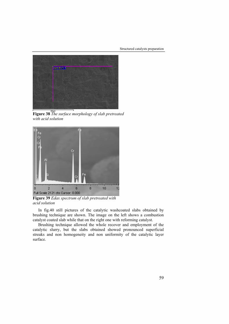
Structured catalysts preparation
59
Figure 38 The surface morphology of slab pretreated with acid solution
Figure 39 Edax spectrum of slab pretreated with acid solution
In fig.40 still pictures of the catalytic washcoated slabs obtained by brushing technique are shown. The image on the left shows a combustion catalyst coated slab while that on the right one with reforming catalyst.
Brushing technique allowed the whole recover and employment of the catalytic slurry, but the slabs obtained showed pronounced superficial streaks and non homogeneity and non uniformity of the catalytic layer surface.
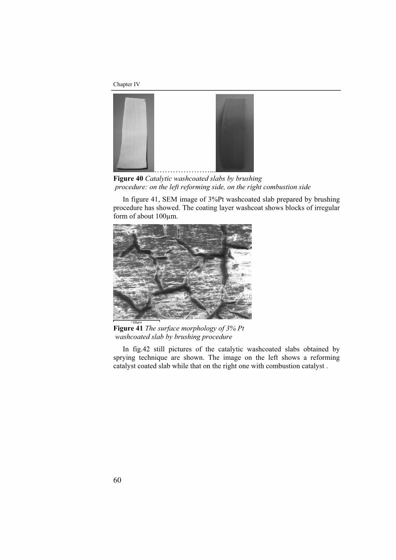
Chapter IV
60
…………………... Figure 40 Catalytic washcoated slabs by brushing procedure: on the left reforming side, on the right combustion side
In figure 41, SEM image of 3%Pt washcoated slab prepared by brushing procedure has showed. The coating layer washcoat shows blocks of irregular form of about 100µm.
Figure 41 The surface morphology of 3% Pt washcoated slab by brushing procedure
In fig.42 still pictures of the catalytic washcoated slabs obtained by sprying technique are shown. The image on the left shows a reforming catalyst coated slab while that on the right one with combustion catalyst .
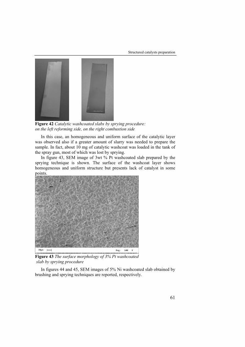
Structured catalysts preparation
61
Figure 42 Catalytic washcoated slabs by sprying procedure: on the left reforming side, on the right combustion side
In this case, an homogeneous and uniform surface of the catalytic layer was observed also if a greater amount of slurry was needed to prepare the sample. In fact, about 10 mg of catalytic washcoat was loaded in the tank of the spray gun, most of which was lost by sprying.
In figure 43, SEM image of 3wt % Pt washcoated slab prepared by the sprying technique is shown. The surface of the washcoat layer shows homogeneous and uniform structure but presents lack of catalyst in some points.
Figure 43 The surface morphology of 3% Pt washcoated slab by sprying procedure
In figures 44 and 45, SEM images of 5% Ni washcoated slab obtained by brushing and sprying techniques are reported, respectively.
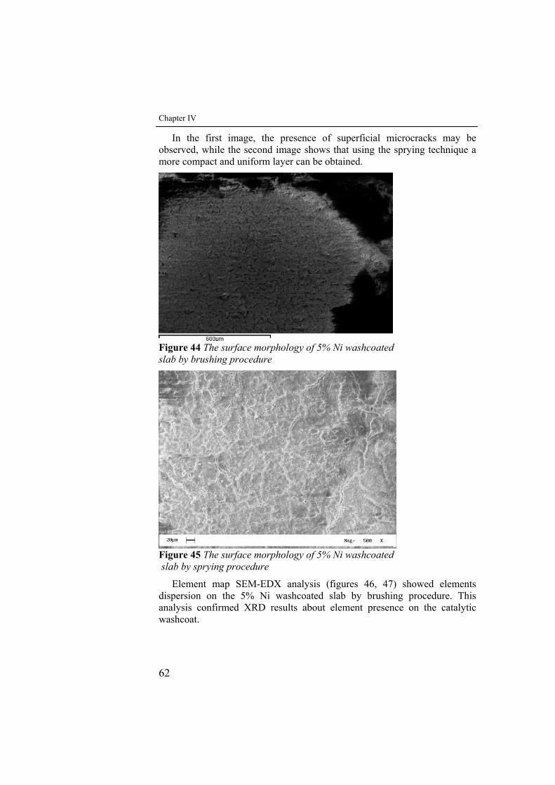
Chapter IV
62
In the first image, the presence of superficial microcracks may be observed, while the second image shows that using the sprying technique a more compact and uniform layer can be obtained.
Figure 44 The surface morphology of 5% Ni washcoated slab by brushing procedure
Figure 45 The surface morphology of 5% Ni washcoated slab by sprying procedure
Element map SEM-EDX analysis (figures 46, 47) showed elements dispersion on the 5% Ni washcoated slab by brushing procedure. This analysis confirmed XRD results about element presence on the catalytic washcoat.
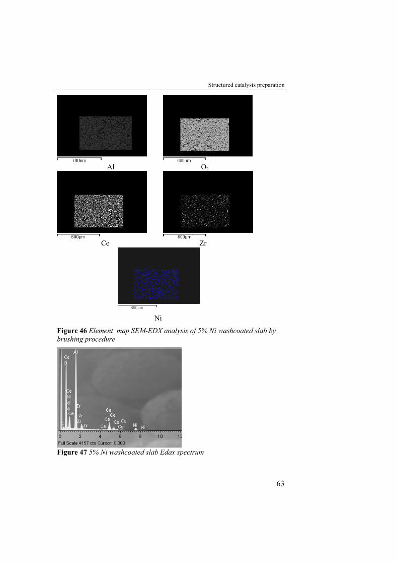
Structured catalysts preparation
63
Al O2
Ce Zr
Ni
Figure 46 Element map SEM-EDX analysis of 5% Ni washcoated slab by brushing procedure
Figure 47 5% Ni washcoated slab Edax spectrum
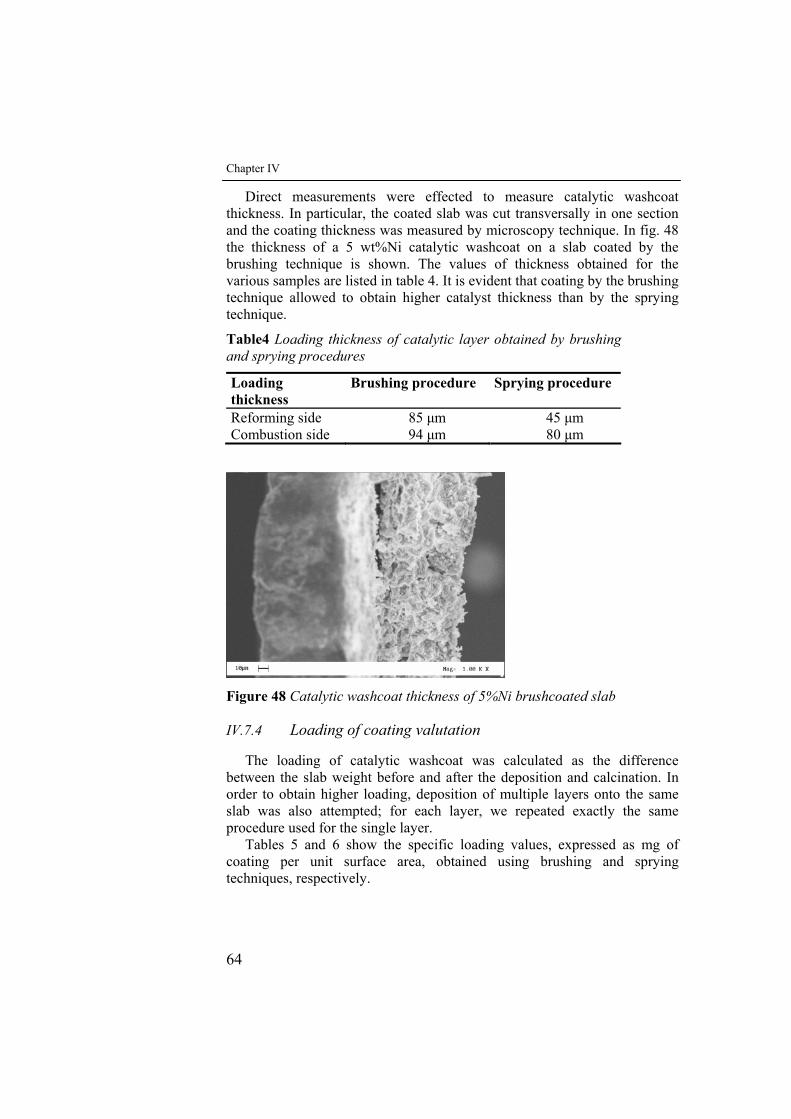
Chapter IV
64
Direct measurements were effected to measure catalytic washcoat thickness. In particular, the coated slab was cut transversally in one section and the coating thickness was measured by microscopy technique. In fig. 48 the thickness of a 5 wt%Ni catalytic washcoat on a slab coated by the brushing technique is shown. The values of thickness obtained for the various samples are listed in table 4. It is evident that coating by the brushing technique allowed to obtain higher catalyst thickness than by the sprying technique.
Table4 Loading thickness of catalytic layer obtained by brushing and sprying procedures
Loading thickness
Brushing procedure Sprying procedure
Reforming side 85 μm 45 μm Combustion side 94 μm 80 μm
Figure 48 Catalytic washcoat thickness of 5%Ni brushcoated slab
IV.7.4 Loading of coating valutation
The loading of catalytic washcoat was calculated as the difference between the slab weight before and after the deposition and calcination. In order to obtain higher loading, deposition of multiple layers onto the same slab was also attempted; for each layer, we repeated exactly the same procedure used for the single layer.
Tables 5 and 6 show the specific loading values, expressed as mg of coating per unit surface area, obtained using brushing and sprying techniques, respectively.
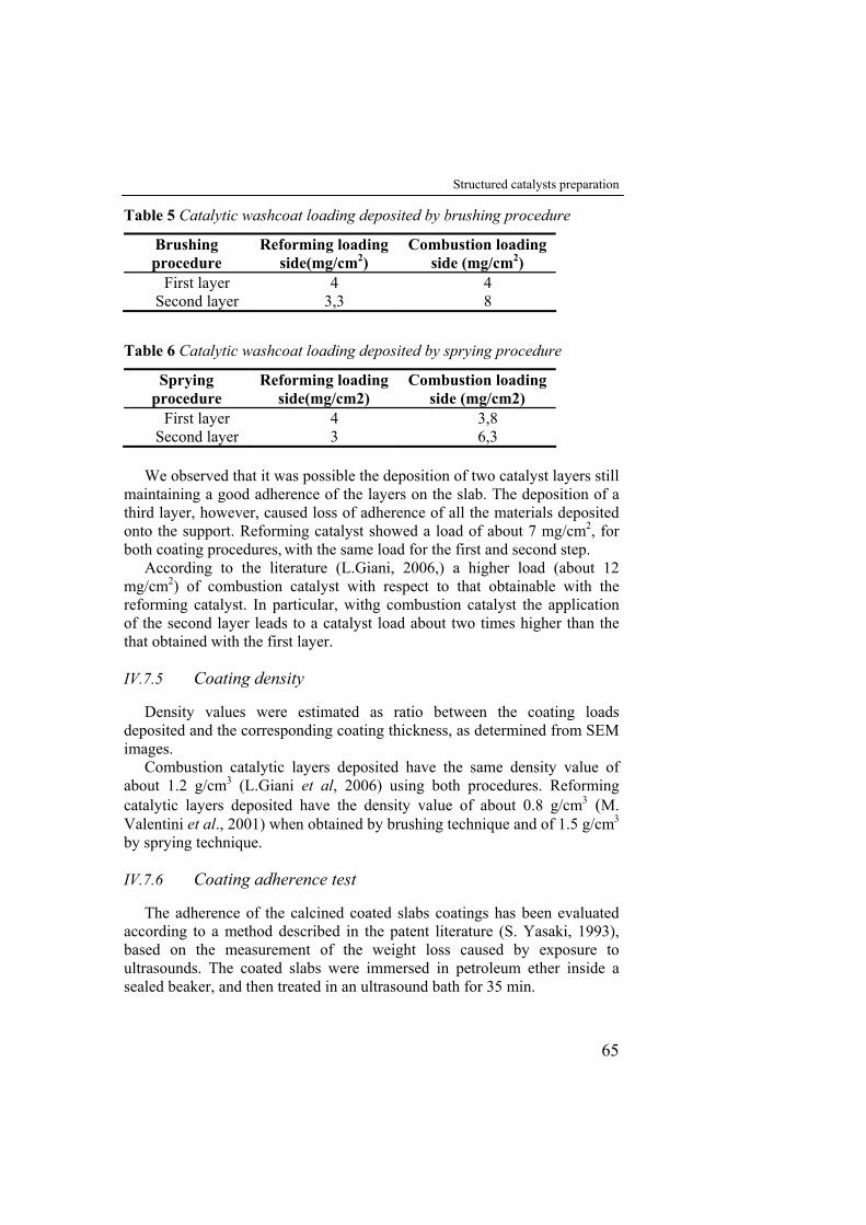
Structured catalysts preparation
65
Table 5 Catalytic washcoat loading deposited by brushing procedure
Brushing procedure
Reforming loading side(mg/cm2)
Combustion loading side (mg/cm2)
First layer 4 4 Second layer 3,3 8
Table 6 Catalytic washcoat loading deposited by sprying procedure
Sprying procedure
Reforming loading side(mg/cm2)
Combustion loading side (mg/cm2)
First layer 4 3,8 Second layer 3 6,3
We observed that it was possible the deposition of two catalyst layers still
maintaining a good adherence of the layers on the slab. The deposition of a third layer, however, caused loss of adherence of all the materials deposited onto the support. Reforming catalyst showed a load of about 7 mg/cm2, for both coating procedures, with the same load for the first and second step.
According to the literature (L.Giani, 2006,) a higher load (about 12 mg/cm2) of combustion catalyst with respect to that obtainable with the reforming catalyst. In particular, withg combustion catalyst the application of the second layer leads to a catalyst load about two times higher than the that obtained with the first layer.
IV.7.5 Coating density
Density values were estimated as ratio between the coating loads deposited and the corresponding coating thickness, as determined from SEM images.
Combustion catalytic layers deposited have the same density value of about 1.2 g/cm3 (L.Giani et al, 2006) using both procedures. Reforming catalytic layers deposited have the density value of about 0.8 g/cm3 (M. Valentini et al., 2001) when obtained by brushing technique and of 1.5 g/cm3 by sprying technique.
IV.7.6 Coating adherence test
The adherence of the calcined coated slabs coatings has been evaluated according to a method described in the patent literature (S. Yasaki, 1993), based on the measurement of the weight loss caused by exposure to ultrasounds. The coated slabs were immersed in petroleum ether inside a sealed beaker, and then treated in an ultrasound bath for 35 min.
Chapter IV
66
The effect of the metallic support oxidation procedure on the catalytic layer adhesion (fig.49) has been then investigated. For the sample oxidized in air at 950°C, the weight loss of the catalytic washcoat during the test in the ultrasonic bath was 6 wt.%. In contrast, the samples oxidized in the 0.5 % O2 mixture showed a better adhesion the weigth loss in the ultrasonic bath resulting of only 1.5 wt.%.
0
1
2
3
4
5
6
7
0 5 10 15 20 25 30 35 40
time,min
Wei
ght l
oss,
%
oxided in air at 950°C oxided in 0,5% O2 atmosphere at 1200°CO2
Figure 49 Weight loss-time curves by ultrasonoc tesing of coated samples oxided at 950°C in air and 1200°C in a 0,5% O2 atmosphere
V EXPERIMENTAL RESULTS: REACTOR TESTS
V.1 Introduction
Chapter V presents and discusses the results of the experiments carried out with the experimental setup described in chapter III. First, results of the cited preliminary tests of only catalytic combustion are shown and discussed, afterwards those pertaining to H2 production as effect of the occurrence of the coupled endothermic and exothermic reactions and the corresponding thermal behavior of the reactor arepresented. Although the experiments were intended to be carried out adiabatically, the results showed that this target was not actually reached and how this influences the reactor performance.
V.2 Combustion preliminary tests
The thermal management of the reactor is influenced by catalytic combustion reaction and then by the performanceof the combustion catalyst and by the operating parameters such as fuel feed ratio, flow rate and temperature. As mentioned above, tests of only combustion were performed in order to evaluate the its thermal impact on the system of the operating conditions to obtain a temperature profile, in the reforming channel, suitable to steam reforming reaction.
Through these tests the influence of the CH4/O2 molar feed ratio and of the gas steam mean residence time (τ) on the system performance were investigated. During theese tests a 50 l/h nitrogen stream, preheated at 500 °C, was fed to the reforming channel.The reduction of the combustion catalyst was unexpectedly investigated as effect of the reduction in situ of the reforming catalyst. In all these tests, temperature profiles in the
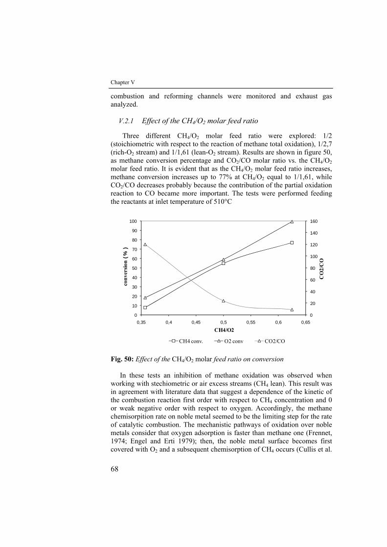
Chapter V
68
combustion and reforming channels were monitored and exhaust gas analyzed.
V.2.1 Effect of the CH4/O2 molar feed ratio
Three different CH4/O2 molar feed ratio were explored: 1/2 (stoichiometric with respect to the reaction of methane total oxidation), 1/2,7 (rich-O2 stream) and 1/1,61 (lean-O2 stream). Results are shown in figure 50, as methane conversion percentage and CO2/CO molar ratio vs. the CH4/O2 molar feed ratio. It is evident that as the CH4/O2 molar feed ratio increases, methane conversion increases up to 77% at CH4/O2 equal to 1/1,61, while CO2/CO decreases probably because the contribution of the partial oxidation reaction to CO became more important. The tests were performed feeding the reactants at inlet temperature of 510°C
0
20
40
60
80
100
120
140
160
0
10
20
30
40
50
60
70
80
90
100
0,35 0,4 0,45 0,5 0,55 0,6 0,65C
O2/
CO
conv
ersio
n(%
)
CH4/O2
CH4 conv. O2 conv CO2/CO Fig. 50: Effect of the CH4/O2 molar feed ratio on conversion
In these tests an inhibition of methane oxidation was observed when working with stechiometric or air excess streams (CH4 lean). This result was in agreement with literature data that suggest a dependence of the kinetic of the combustion reaction first order with respect to CH4 concentration and 0 or weak negative order with respect to oxygen. Accordingly, the methane chemisorpition rate on noble metal seemed to be the limiting step for the rate of catalytic combustion. The mechanistic pathways of oxidation over noble metals consider that oxygen adsorption is faster than methane one (Frennet, 1974; Engel and Erti 1979); then, the noble metal surface becomes first covered with O2 and a subsequent chemisorption of CH4 occurs (Cullis et al.
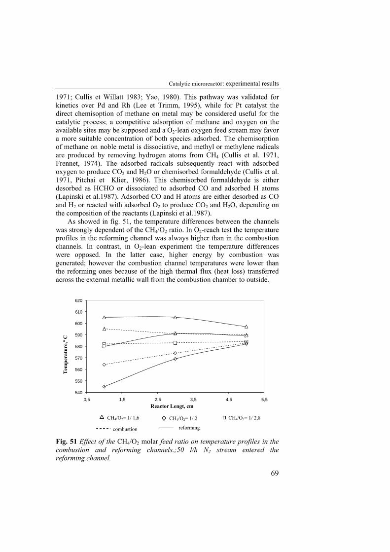
Catalytic microreactor: experimental results
69
1971; Cullis et Willatt 1983; Yao, 1980). This pathway was validated for kinetics over Pd and Rh (Lee et Trimm, 1995), while for Pt catalyst the direct chemisoption of methane on metal may be considered useful for the catalytic process; a competitive adsorption of methane and oxygen on the available sites may be supposed and a O2-lean oxygen feed stream may favor a more suitable concentration of both species adsorbed. The chemisorption of methane on noble metal is dissociative, and methyl or methylene radicals are produced by removing hydrogen atoms from CH4 (Cullis et al. 1971, Frennet, 1974). The adsorbed radicals subsequently react with adsorbed oxygen to produce CO2 and H2O or chemisorbed formaldehyde (Cullis et al. 1971, Pitchai et Klier, 1986). This chemisorbed formaldehyde is either desorbed as HCHO or dissociated to adsorbed CO and adsorbed H atoms (Lapinski et al.1987). Adsorbed CO and H atoms are either desorbed as CO and H2 or reacted with adsorbed O2 to produce CO2 and H2O, depending on the composition of the reactants (Lapinski et al.1987).
As showed in fig. 51, the temperature differences between the channels was strongly dependent of the CH4/O2 ratio. In O2-reach test the temperature profiles in the reforming channel was always higher than in the combustion channels. In contrast, in O2-lean experiment the temperature differences were opposed. In the latter case, higher energy by combustion was generated; however the combustion channel temperatures were lower than the reforming ones because of the high thermal flux (heat loss) transferred across the external metallic wall from the combustion chamber to outside.
540
550
560
570
580
590
600
610
620
0,5 1,5 2,5 3,5 4,5 5,5
Tem
pera
ture
,°C
Reactor Lengt, cm
Fig. 51 Effect of the CH4/O2 molar feed ratio on temperature profiles in the combustion and reforming channels.;50 l/h N2 stream entered the reforming channel.
CH4/O2= 1/ 1,6 CH4/O2= 1/ 2 CH4/O2= 1/ 2,8
combustion reforming
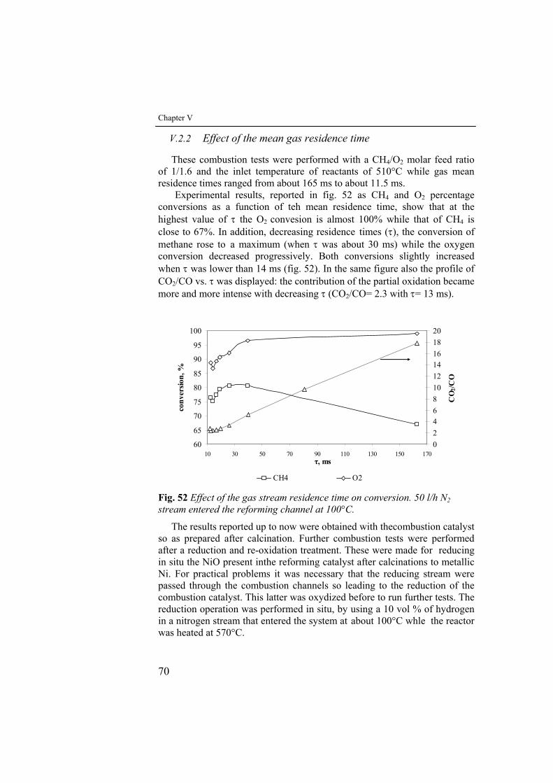
Chapter V
70
V.2.2 Effect of the mean gas residence time
These combustion tests were performed with a CH4/O2 molar feed ratio of 1/1.6 and the inlet temperature of reactants of 510°C while gas mean residence times ranged from about 165 ms to about 11.5 ms.
Experimental results, reported in fig. 52 as CH4 and O2 percentage conversions as a function of teh mean residence time, show that at the highest value of τ the O2 convesion is almost 100% while that of CH4 is close to 67%. In addition, decreasing residence times (τ), the conversion of methane rose to a maximum (when τ was about 30 ms) while the oxygen conversion decreased progressively. Both conversions slightly increased when τ was lower than 14 ms (fig. 52). In the same figure also the profile of CO2/CO vs. τ was displayed: the contribution of the partial oxidation became more and more intense with decreasing τ (CO2/CO= 2.3 with τ= 13 ms).
60
65
70
75
80
85
90
95
100
10 30 50 70 90 110 130 150 170
conv
ersio
n, %
02468101214161820
CO
2/CO
CH4 O2
τ, ms
Fig. 52 Effect of the gas stream residence time on conversion. 50 l/h N2 stream entered the reforming channel at 100°C.
The results reported up to now were obtained with thecombustion catalyst so as prepared after calcination. Further combustion tests were performed after a reduction and re-oxidation treatment. These were made for reducing in situ the NiO present inthe reforming catalyst after calcinations to metallic Ni. For practical problems it was necessary that the reducing stream were passed through the combustion channels so leading to the reduction of the combustion catalyst. This latter was oxydized before to run further tests. The reduction operation was performed in situ, by using a 10 vol % of hydrogen in a nitrogen stream that entered the system at about 100°C whle the reactor was heated at 570°C.
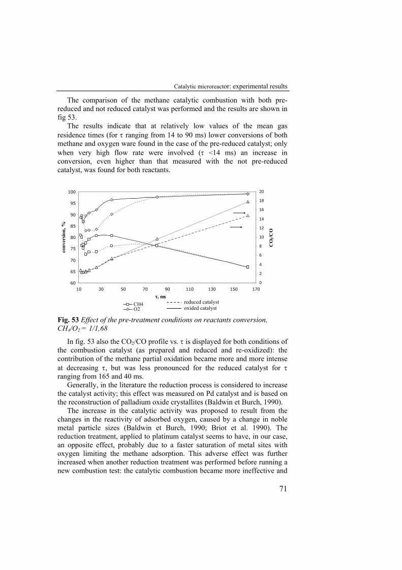
Catalytic microreactor: experimental results
71
The comparison of the methane catalytic combustion with both pre-reduced and not reduced catalyst was performed and the results are shown in fig 53.
The results indicate that at relatively low values of the mean gas residence times (for τ ranging from 14 to 90 ms) lower conversions of both methane and oxygen ware found in the case of the pre-reduced catalyst; only when very high flow rate were involved (τ <14 ms) an increase in conversion, even higher than that measured with the not pre-reduced catalyst, was found for both reactants.
60
65
70
75
80
85
90
95
100
10 30 50 70 90 110 130 150 170
conv
ersio
n, %
0
2
4
6
8
10
12
14
16
18
20
CO
2/CO
CH4O2
τ, ms
Fig. 53 Effect of the pre-treatment conditions on reactants conversion, CH4/O2 = 1/1,68
In fig. 53 also the CO2/CO profile vs. τ is displayed for both conditions of the combustion catalyst (as prepared and reduced and re-oxidized): the contribution of the methane partial oxidation became more and more intense at decreasing τ, but was less pronounced for the reduced catalyst for τ ranging from 165 and 40 ms.
Generally, in the literature the reduction process is considered to increase the catalyst activity; this effect was measured on Pd catalyst and is based on the reconstruction of palladium oxide crystallites (Baldwin et Burch, 1990).
The increase in the catalytic activity was proposed to result from the changes in the reactivity of adsorbed oxygen, caused by a change in noble metal particle sizes (Baldwin et Burch, 1990; Briot et al. 1990). The reduction treatment, applied to platinum catalyst seems to have, in our case, an opposite effect, probably due to a faster saturation of metal sites with oxygen limiting the methane adsorption. This adverse effect was further increased when another reduction treatment was performed before running a new combustion test: the catalytic combustion became more ineffective and
reduced catalyst oxided catalyst
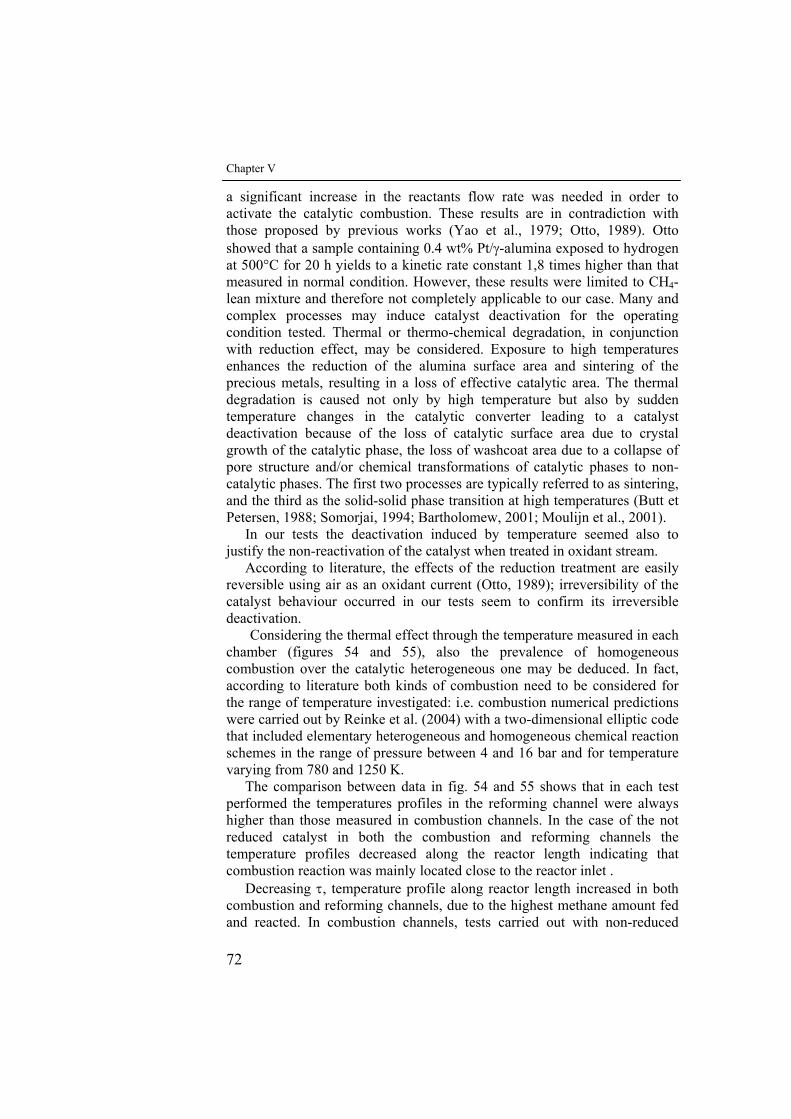
Chapter V
72
a significant increase in the reactants flow rate was needed in order to activate the catalytic combustion. These results are in contradiction with those proposed by previous works (Yao et al., 1979; Otto, 1989). Otto showed that a sample containing 0.4 wt% Pt/γ-alumina exposed to hydrogen at 500°C for 20 h yields to a kinetic rate constant 1,8 times higher than that measured in normal condition. However, these results were limited to CH4-lean mixture and therefore not completely applicable to our case. Many and complex processes may induce catalyst deactivation for the operating condition tested. Thermal or thermo-chemical degradation, in conjunction with reduction effect, may be considered. Exposure to high temperatures enhances the reduction of the alumina surface area and sintering of the precious metals, resulting in a loss of effective catalytic area. The thermal degradation is caused not only by high temperature but also by sudden temperature changes in the catalytic converter leading to a catalyst deactivation because of the loss of catalytic surface area due to crystal growth of the catalytic phase, the loss of washcoat area due to a collapse of pore structure and/or chemical transformations of catalytic phases to non-catalytic phases. The first two processes are typically referred to as sintering, and the third as the solid-solid phase transition at high temperatures (Butt et Petersen, 1988; Somorjai, 1994; Bartholomew, 2001; Moulijn et al., 2001).
In our tests the deactivation induced by temperature seemed also to justify the non-reactivation of the catalyst when treated in oxidant stream.
According to literature, the effects of the reduction treatment are easily reversible using air as an oxidant current (Otto, 1989); irreversibility of the catalyst behaviour occurred in our tests seem to confirm its irreversible deactivation.
Considering the thermal effect through the temperature measured in each chamber (figures 54 and 55), also the prevalence of homogeneous combustion over the catalytic heterogeneous one may be deduced. In fact, according to literature both kinds of combustion need to be considered for the range of temperature investigated: i.e. combustion numerical predictions were carried out by Reinke et al. (2004) with a two-dimensional elliptic code that included elementary heterogeneous and homogeneous chemical reaction schemes in the range of pressure between 4 and 16 bar and for temperature varying from 780 and 1250 K.
The comparison between data in fig. 54 and 55 shows that in each test performed the temperatures profiles in the reforming channel were always higher than those measured in combustion channels. In the case of the not reduced catalyst in both the combustion and reforming channels the temperature profiles decreased along the reactor length indicating that combustion reaction was mainly located close to the reactor inlet .
Decreasing τ, temperature profile along reactor length increased in both combustion and reforming channels, due to the highest methane amount fed and reacted. In combustion channels, tests carried out with non-reduced
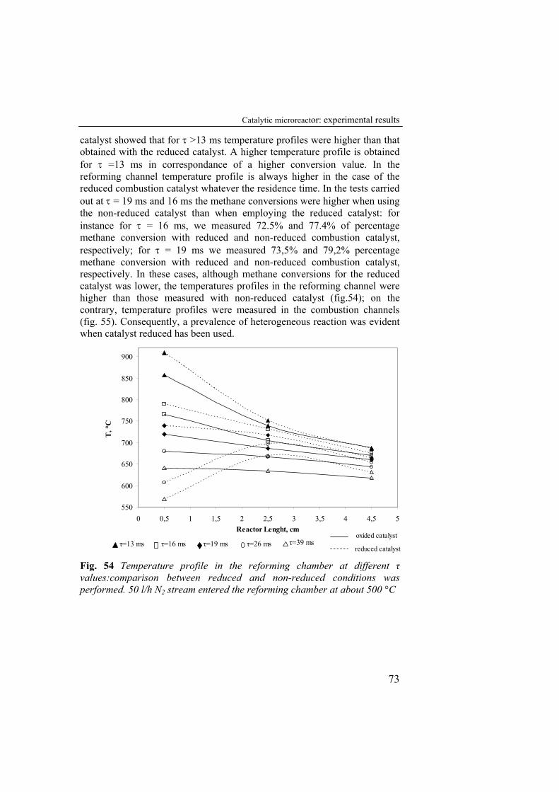
Catalytic microreactor: experimental results
73
catalyst showed that for τ >13 ms temperature profiles were higher than that obtained with the reduced catalyst. A higher temperature profile is obtained for τ =13 ms in correspondance of a higher conversion value. In the reforming channel temperature profile is always higher in the case of the reduced combustion catalyst whatever the residence time. In the tests carried out at τ = 19 ms and 16 ms the methane conversions were higher when using the non-reduced catalyst than when employing the reduced catalyst: for instance for τ = 16 ms, we measured 72.5% and 77.4% of percentage methane conversion with reduced and non-reduced combustion catalyst, respectively; for τ = 19 ms we measured 73,5% and 79,2% percentage methane conversion with reduced and non-reduced combustion catalyst, respectively. In these cases, although methane conversions for the reduced catalyst was lower, the temperatures profiles in the reforming channel were higher than those measured with non-reduced catalyst (fig.54); on the contrary, temperature profiles were measured in the combustion channels (fig. 55). Consequently, a prevalence of heterogeneous reaction was evident when catalyst reduced has been used.
550
600
650
700
750
800
850
900
0 0,5 1 1,5 2 2,5 3 3,5 4 4,5 5Reactor Lenght, cm
T, °
C
τ=13 ms τ=16 ms τ=19 ms τ=26 ms τ=39 msreduced catalyst
oxided catalyst
Fig. 54 Temperature profile in the reforming chamber at different τ values:comparison between reduced and non-reduced conditions was performed. 50 l/h N2 stream entered the reforming chamber at about 500 °C
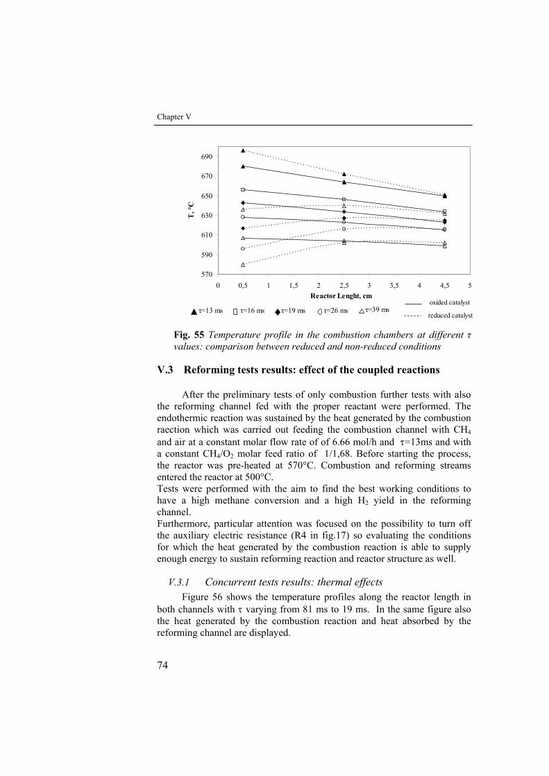
Chapter V
74
570
590
610
630
650
670
690
0 0,5 1 1,5 2 2,5 3 3,5 4 4,5 5Reactor Lenght, cm
T, °
C
τ=13 ms τ=16 ms τ=19 ms τ=26 ms τ=39 msreduced catalyst
oxided catalyst
Fig. 55 Temperature profile in the combustion chambers at different τ values: comparison between reduced and non-reduced conditions
V.3 Reforming tests results: effect of the coupled reactions
After the preliminary tests of only combustion further tests with also the reforming channel fed with the proper reactant were performed. The endothermic reaction was sustained by the heat generated by the combustion raection which was carried out feeding the combustion channel with CH4 and air at a constant molar flow rate of of 6.66 mol/h and τ=13ms and with a constant CH4/O2 molar feed ratio of 1/1,68. Before starting the process, the reactor was pre-heated at 570°C. Combustion and reforming streams entered the reactor at 500°C. Tests were performed with the aim to find the best working conditions to have a high methane conversion and a high H2 yield in the reforming channel. Furthermore, particular attention was focused on the possibility to turn off the auxiliary electric resistance (R4 in fig.17) so evaluating the conditions for which the heat generated by the combustion reaction is able to supply enough energy to sustain reforming reaction and reactor structure as well.
V.3.1 Concurrent tests results: thermal effects Figure 56 shows the temperature profiles along the reactor length in
both channels with τ varying from 81 ms to 19 ms. In the same figure also the heat generated by the combustion reaction and heat absorbed by the reforming channel are displayed.
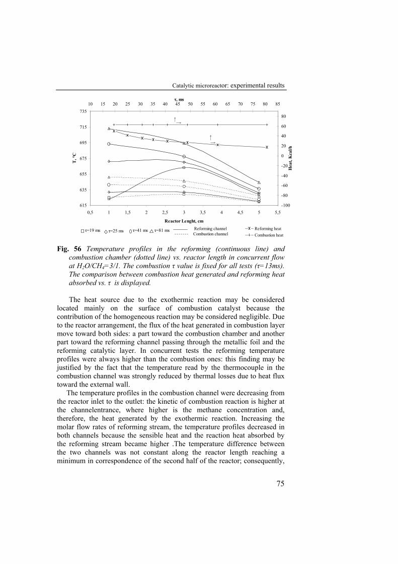
Catalytic microreactor: experimental results
75
615
635
655
675
695
715
735
0,5 1 1,5 2 2,5 3 3,5 4 4,5 5 5,5
Reactor Lenght, cm
T, °
C
-100
-80
-60
-40
-20
0
20
40
60
80
10 15 20 25 30 35 40 45 50 55 60 65 70 75 80 85
Hea
t, K
cal/h
Reforming heatCombustion heat
τ=81 msτ=19 ms τ=25 msCombustion channelReforming channelτ=41 ms
τ, msτ, ms
Fig. 56 Temperature profiles in the reforming (continuous line) and
combustion chamber (dotted line) vs. reactor length in concurrent flow at H2O/CH4=3/1. The combustion τ value is fixed for all tests (τ=13ms). The comparison between combustion heat generated and reforming heat absorbed vs. τ is displayed.
The heat source due to the exothermic reaction may be considered
located mainly on the surface of combustion catalyst because the contribution of the homogeneous reaction may be considered negligible. Due to the reactor arrangement, the flux of the heat generated in combustion layer move toward both sides: a part toward the combustion chamber and another part toward the reforming channel passing through the metallic foil and the reforming catalytic layer. In concurrent tests the reforming temperature profiles were always higher than the combustion ones: this finding may be justified by the fact that the temperature read by the thermocouple in the combustion channel was strongly reduced by thermal losses due to heat flux toward the external wall.
The temperature profiles in the combustion channel were decreasing from the reactor inlet to the outlet: the kinetic of combustion reaction is higher at the channelentrance, where higher is the methane concentration and, therefore, the heat generated by the exothermic reaction. Increasing the molar flow rates of reforming stream, the temperature profiles decreased in both channels because the sensible heat and the reaction heat absorbed by the reforming stream became higher .The temperature difference between the two channels was not constant along the reactor length reaching a minimum in correspondence of the second half of the reactor; consequently,

Chapter V
76
higher endothermic heat absorption with respect to heat generation may be supposed in that part of the system.
Increasing the molar flow rate of the reforming stream (τ < 25 ms) the endothermic temperature profile tended to reach a maximum in correspondence of the middle of the reactor. Feeding such a high flow rates, due to the high values of both sensible and reaction heats absorbed, the inlet endothermic temperature decreased, till to become equal to the combustion channel temperature (τ = 19ms). For τ = 19 ms the heat absorbed by the reforming stream became too high and the reactor started to cool down.
Consequently, stable thermal conditions only when operating with τ > 25 ms were achieved.
Figure 57 shows the temperature profiles along the reactor length in both channels with the H2O/CH4 feed molar ratio varying from 3 to 11.3. In this case the increase of water flow rate in the reforming chamber did not cause any appreciable variation in the combustion temperature profiles. The temperature inside the reforming channel closer to the channel inlet decreased progressively with increasing H2O/CH4 feed molar ratio.
However, the trend of temperatures read in the middle point of the endothermic channel with the value of the H2O/CH4 feed molar ratio was inverse of that registered for the temperatures close to the channel inlet: higher temperatures in the middle point were recorded at higher steam flow rates. This finding may be justified considering that under these conditions exothermic water gas shift reaction is promoted, and its extent increased at increasing water contents.
The heat absorbed by the reforming current increased linearly at increasing water content. Operating with a steam to methane ratio varying from 3 to 11.3, the thermal stability of the system was not disturbed; however, as will be showed in following (fig. 62), high steam content affected seriously the methane conversion and, therefore, the system efficiency, in terms of H2 productivity, was compromised
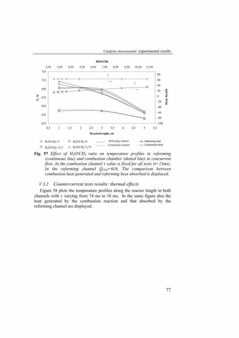
Catalytic microreactor: experimental results
77
615
635
655
675
695
715
735
0,5 1 1,5 2 2,5 3 3,5 4 4,5 5 5,5
ReactorLenght, cm
T, °
C
-100
-80
-60
-40
-20
0
20
40
60
80
2,50 3,50 4,50 5,50 6,50 7,50 8,50 9,50 10,50 11,50
H2O/CH4
Hea
t, K
cal/h
Reforming heatCombustion heat
H2O/CH4=3
H2O/CH4=11,3
H2O/CH4=9 Combustion channelReforming channel
H2O/CH4=3,75 Fig. 57 Effect of H2O/CH4 ratio on temperature profiles in reforming
(continuous line) and combustion chamber (dotted line) in concurrent flow. In the combustion channel τ value is fixed for all tests (τ=13ms). In the reforming channel QCH4=6l/h. The comparison between combustion heat generated and reforming heat absorbed is displayed.
V.3.2 Countercurrent tests results: thermal effects Figure 58 plots the temperature profiles along the reactor length in both
channels with τ varying from 74 ms to 18 ms. In the same figure also the heat generated by the combustion reaction and that absorbed by the reforming channel are displayed.
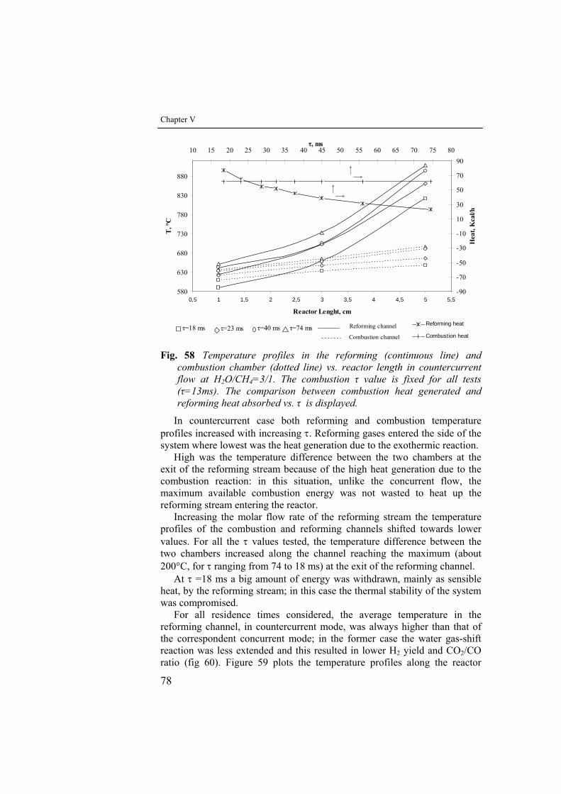
Chapter V
78
580
630
680
730
780
830
880
0,5 1 1,5 2 2,5 3 3,5 4 4,5 5 5,5
Reactor Lenght, cm
T, °
C
-90
-70
-50
-30
-10
10
30
50
70
9010 15 20 25 30 35 40 45 50 55 60 65 70 75 80
Hea
t, K
cal/h
Reforming heat
Combustion heat
τ, ms
τ=74 msτ=18 ms τ=23 msCombustion channel
Reforming channelτ=40 ms
Fig. 58 Temperature profiles in the reforming (continuous line) and
combustion chamber (dotted line) vs. reactor length in countercurrent flow at H2O/CH4=3/1. The combustion τ value is fixed for all tests (τ=13ms). The comparison between combustion heat generated and reforming heat absorbed vs. τ is displayed.
In countercurrent case both reforming and combustion temperature profiles increased with increasing τ. Reforming gases entered the side of the system where lowest was the heat generation due to the exothermic reaction.
High was the temperature difference between the two chambers at the exit of the reforming stream because of the high heat generation due to the combustion reaction: in this situation, unlike the concurrent flow, the maximum available combustion energy was not wasted to heat up the reforming stream entering the reactor.
Increasing the molar flow rate of the reforming stream the temperature profiles of the combustion and reforming channels shifted towards lower values. For all the τ values tested, the temperature difference between the two chambers increased along the channel reaching the maximum (about 200°C, for τ ranging from 74 to 18 ms) at the exit of the reforming channel.
At τ =18 ms a big amount of energy was withdrawn, mainly as sensible heat, by the reforming stream; in this case the thermal stability of the system was compromised.
For all residence times considered, the average temperature in the reforming channel, in countercurrent mode, was always higher than that of the correspondent concurrent mode; in the former case the water gas-shift reaction was less extended and this resulted in lower H2 yield and CO2/CO ratio (fig 60). Figure 59 plots the temperature profiles along the reactor
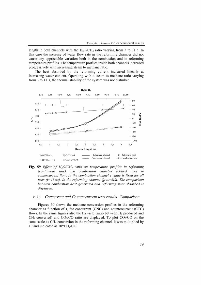
Catalytic microreactor: experimental results
79
length in both channels with the H2O/CH4 ratio varying from 3 to 11.3. In this case the increase of water flow rate in the reforming chamber did not cause any appreciable variation both in the combustion and in reforming temperature profiles. The temperature profiles inside both channels increased progressively with increasing steam to methane ratio.
The heat absorbed by the reforming current increased linearly at increasing water content. Operating with a steam to methane ratio varying from 3 to 11.3, the thermal stability of the system was not disturbed.
580
630
680
730
780
830
880
0,5 1 1,5 2 2,5 3 3,5 4 4,5 5 5,5
Reactor Lenght, cm
T, °
C
-100
-80
-60
-40
-20
0
20
40
60
80
2,50 3,50 4,50 5,50 6,50 7,50 8,50 9,50 10,50 11,50
H2O/CH4
Hea
t, K
cal/h
Reforming heatCombustion heat
H2O/CH4=3
H2O/CH4=11,3
H2O/CH4=9 Combustion channel
Reforming channel
H2O/CH4=3,75
1
Fig. 59 Effect of H2O/CH4 ratio on temperature profiles in reforming
(continuous line) and combustion chamber (dotted line) in contercurrent flow. In the combustion channel τ value is fixed for all tests (τ=13ms). In the reforming channel QCH4=6l/h. The comparison between combustion heat generated and reforming heat absorbed is displayed.
V.3.3 Concurrent and Countercurrent tests results: Comparison
Figures 60 shows the methane conversion profiles in the reforming chamber as function of τ, for concurrent (CNC) and countercurrent (CTC) flows. In the same figures also the H2 yield (ratio between H2 produced and CH4 converted) and CO2/CO ratio are displayed. To plot CO2/CO on the same scale as CH4 conversion in the reforming channel, it was multiplied by 10 and indicated as 10*CO2/CO.
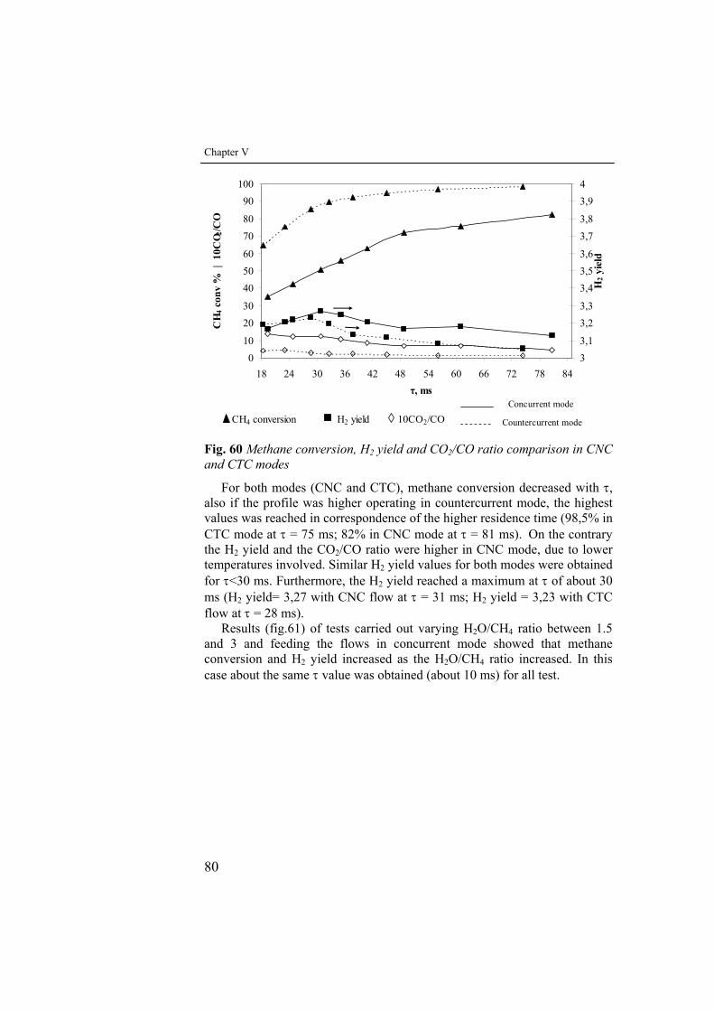
Chapter V
80
010
2030
405060
7080
90100
18 24 30 36 42 48 54 60 66 72 78 84
CH
4 con
v %
| 1
0CO 2
/CO
33,1
3,23,3
3,43,53,6
3,73,8
3,94
H2 y
ield
CH4 conversion H2 yield 10CO2/CO Countercurrent mode
Concurrent modeτ, ms
Fig. 60 Methane conversion, H2 yield and CO2/CO ratio comparison in CNC and CTC modes
For both modes (CNC and CTC), methane conversion decreased with τ, also if the profile was higher operating in countercurrent mode, the highest values was reached in correspondence of the higher residence time (98,5% in CTC mode at τ = 75 ms; 82% in CNC mode at τ = 81 ms). On the contrary the H2 yield and the CO2/CO ratio were higher in CNC mode, due to lower temperatures involved. Similar H2 yield values for both modes were obtained for τ<30 ms. Furthermore, the H2 yield reached a maximum at τ of about 30 ms (H2 yield= 3,27 with CNC flow at τ = 31 ms; H2 yield = 3,23 with CTC flow at τ = 28 ms).
Results (fig.61) of tests carried out varying H2O/CH4 ratio between 1.5 and 3 and feeding the flows in concurrent mode showed that methane conversion and H2 yield increased as the H2O/CH4 ratio increased. In this case about the same τ value was obtained (about 10 ms) for all test.
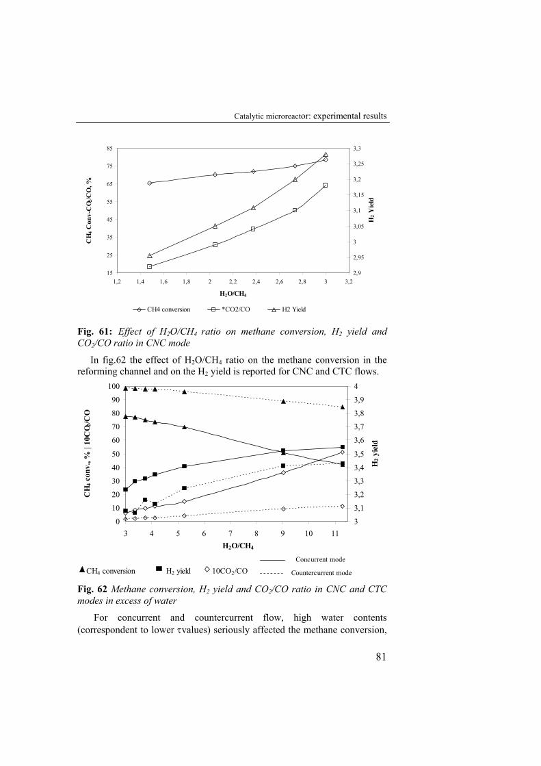
Catalytic microreactor: experimental results
81
15
25
35
45
55
65
75
85
1,2 1,4 1,6 1,8 2 2,2 2,4 2,6 2,8 3 3,2
H2O/CH4
CH
4 Con
v-C
O 2/C
O, %
2,9
2,95
3
3,05
3,1
3,15
3,2
3,25
3,3
H2 Y
ield
CH4 conversion *CO2/CO H2 Yield
Fig. 61: Effect of H2O/CH4 ratio on methane conversion, H2 yield and CO2/CO ratio in CNC mode
In fig.62 the effect of H2O/CH4 ratio on the methane conversion in the reforming channel and on the H2 yield is reported for CNC and CTC flows.
0
10
20
30
40
50
60
70
80
90
100
3 4 5 6 7 8 9 10 11H2O/CH4
CH
4 con
v., %
| 10
CO 2
/CO
3
3,1
3,2
3,3
3,4
3,5
3,6
3,7
3,8
3,9
4H
2 yie
ld
CH4 conversion H2 yield 10CO2/CO Countercurrent mode
Concurrent mode
Fig. 62 Methane conversion, H2 yield and CO2/CO ratio in CNC and CTC modes in excess of water
For concurrent and countercurrent flow, high water contents (correspondent to lower τvalues) seriously affected the methane conversion,
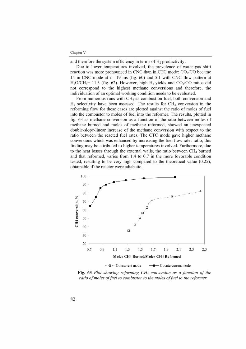
Chapter V
82
and therefore the system efficiency in terms of H2 productivity. Due to lower temperatures involved, the prevalence of water gas shift
reaction was more pronounced in CNC than in CTC mode: CO2/CO became 14 in CNC mode at τ= 19 ms (fig. 60) and 5.1 with CNC flow pattern at H2O/CH4= 11.3 (fig. 62). However, high H2 yields and CO2/CO ratios did not correspond to the highest methane conversions and therefore, the individuation of an optimal working condition needs to be evaluated.
From numerous runs with CH4 as combustion fuel, both conversion and H2 selectivity have been assessed. The results for CH4 conversion in the reforming flow for these cases are plotted against the ratio of moles of fuel into the combustor to moles of fuel into the reformer. The results, plotted in fig. 63 as methane conversion as a function of the ratio between moles of methane burned and moles of methane reformed, showed an unexpected double-slope-linear increase of the methane conversion with respect to the ratio between the reacted fuel rates. The CTC mode gave higher methane conversions which was enhanced by increasing the fuel flow rates ratio; this finding may be attributed to higher temperatures involved. Furthermore, due to the heat losses through the external walls, the ratio between CH4 burned and that reformed, varies from 1.4 to 0.7 in the more fovorable condition tested, resulting to be very high compared to the theoretical value (0.25), obtainable if the reactor were adiabatic.
20
30
40
50
60
70
80
90
100
0,7 0,9 1,1 1,3 1,5 1,7 1,9 2,1 2,3 2,5
Moles CH4 Burned/Moles CH4 Reformed
CH
4 co
nver
sion,
%
Concurrent mode Countercurrent mode Fig. 63 Plot showing reforming CH4 conversion as a function of the ratio of moles of fuel to combustor to the moles of fuel to the reformer.
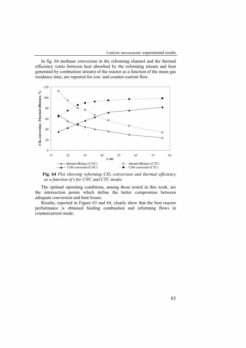
Catalytic microreactor: experimental results
83
In fig. 64 methane conversion in the reforming channel and the thermal efficiency (ratio between heat absorbed by the reforming stream and heat generated by combustion stream) of the reactor as a function of the mean gas residence time, are reported for con- and counter-current flow.
0
20
40
60
80
100
120
15 25 35 45 55 65 75 85
CH
4 con
vers
ion
| The
rmal
effi
cien
cy, %
thermal efficiency (CNC) thermal efficiency (CTC) CH4 conversion (CNC) CH4 conversion (CTC)
τ, ms
Fig. 64 Plot showing reforming CH4 conversion and thermal efficiency as a function of τ for CNC and CTC modes
The optimal operating conditions, among those tested in this work, are the intersection points which define the better compromise between adequate conversion and heat losses.
Results, reported in Figure 63 and 64, clearly show that the best reactor performance is obtained feeding combustion and reforming flows in countercurrent mode.

VI Conclusions
The current work has proposed a novel reactor design for efficient
hydrogen production where catalytic combustion of CH4 produces the necessary heat to drive CH4 steam reforming occurring on the opposite side of a shared metallic plate. Indeed, a mesoscale catalytic plate reactor has been designed, assembled and instrumented for laboratory tests.
The reactor showed the following properties:
• Compactness, suitable as portable hydrogen generator; • Versatility, it’s possible to change easily mass flow rates and
temperatures of the reactants, process temperatures, catalyst load and streams flow pattern (equi- or counter-current)
• Accessibility, it’s suitable for carrying out easy and quick measurements of process parameters, catalyst substitution and control of the reactor operation;
• Flexibility, given the main aim of hydrogen generation, is able to easily test different catalyst for the same reacting system (exothermic and endothermic reactions) or different reactants;
• Integration, to provide energy for the endothermic reaction by integration of an exothermic reaction within the same reactor;
• Control, to obtain that the endothermic reaction results also structurally connected with the exhotermic reaction by controlling of the heat generation and transfer.
The optimization of the catalyst employed in the microstructured reactor
has been carried out. The oxidation of aluchrom support in 0.5 vol % O2 atmosphere at 1200 °C for 10 min had shown a better adhesion of catalytic layer than oxidation pre-treatment in air at 950°C.
Chapter VIII
86
The washcoat (38.5% solid content) employed, was suitable as catalyst support for both catalytic reactions: characterisation tests showed high superficial area in correspondence of γ-Al2O3 presence; CeO2–ZrO2 and La2O3 have oxygen storage and stabilizing properties respectively. Two catalyst deposition techniques were tested: the brushing and sprying procedures. The former performed better than the latter by giving a quite adherent catalytic layer and better catalyst dispersion. It was possible to deposit two catalyst layers on the aluchrom support still maintaining a good adherence with both procedures. Deposition of a third layer, however, caused the loss of adherence of all the materials coated onto the support. SEM-EDX analysis showed a good elements dispersion. Homogeneous and uniform surface of catalytic layer was observed using sprying procedure also if a greater amount of slurry was lost. Brushing procedure allowed to obtain a higher washcoat loading and higher thickness than sprying procedure but the correspondent density value was lower for reforming catalyst.
The reactor designed and realised was able to operate in a stable way in a wide range of operating conditions.
Preliminary combustion tests showed that methane conversion was strongly dependent by the CH4/O2 ratio and residence time in the combustion channel. Three different feeding ratio of CH4/O2 were considered, experimental results showed that methane conversion increased up to 77% at CH4/O2 equal to 1/1,68. Fixed CH4/O2 ratio(1/1,68), methane conversion rose to a maximum of 80% for τ varying between 25 and 40 ms.
According to the temperature profiles registered in both channels the system showed very high heat transfer rate from the combustion catalyst to the reforming catalyst, a temperature profile in the internal channel suitable for steam reforming reaction was observed for τ=13 ms. The results of preliminary tests fixed the optimal conditions: CH4/ O2 feed ratio equal to 1/1,68 and τ equal to 13 ms.manca ilverbo che vuol dire questa frase?
A lower conversion of both methane and oxygen was found for the reduced and re-oxidized catalyst with respect to the not reduced catalyst for τ ranging from 14 to 162 ms; only when high flow rate were involved (τ<14 ms) an increase in conversion, even higher than that measured for the not reduced catalyst, was found probably due to the catalyst re-oxidation.
In the reforming/combustion tests a wide range of the operative conditions have been explorated. The methane conversion in reforming channel was enhanced increasing τ values, in correspondence of concurrent and countercurrent mode, and the highest values were reached in correspondence of the higher residence times (98,5% in CTC mode at τ = 74,4 ms; 82% in CNC mode at τ = 80,7 ms). The H2 yield along with CO2/CO ratio was higher in concurrent tests: the water gas shift contribution to the total CH4 conversion was higher due to the lower temperatures reached.
Catalytic microreactor: experimental results
87
Moreover, the H2 yield reached a maximum for τ=30ms in both CNC and CTC modes. The countercurrent flow pattern allows better reactor performance whatever the other operating parameters. showed the higher CH4 conversion, 98% for τ=81 ms, together with a H2 productivity (3 mol H2/ mol CH4in).
The H2O/CH4 ratio affects the methane conversion in reforming channel, as reported by thermodinamical study, but not significantly the thermal reforming profiles.
Increasing H2O/CH4 ratio from 1.5 to 3 for τ=10 ms, methane conversion and H2 selectivity increased. Increasing H2O/CH4 ratio from 3 to 11.3 at a 6 l/h methane flowrate , methane conversion decreased but higher H2 selectivity was obtained.
Due to the heat losses, the ratio between CH4 reformed and CH4 burned was far compared to the theoretical value (4) for adiabatic process, varying from 0.7 to 1.4 in the best operating conditions tested.
The autothermal stability of the system was proved for a given combustion condition (τ=13 ms,CH4/O2 = 1/1,68) with τref≥25ms and 3≤H2O/CH4≤11.3. This result was obtained in concurrent and countercurrent flows.

VII References
Alepee C., Paratte L., Renaud P.,. Maurer R, Renken A. Fast heating and cooling for high temperature chemical microreactors, in: W. Ehrfeld (Ed.), Proceedings of the Fourth International Conference on Microreaction Engineering, Springer, 2000, Berlin, p. 514.
Alstrup, I. (1988) A new model explaining carbon filament growth on nickel, iron and nickel-copper alloy catalysts, J. Catal., 109(2), 241-251
Gard, N.R. (1966) Nitrogen, 39, 25 Anderson R.B., Stein K.C., Feenan J.J., Hofer L.J.E. (1961) Catalytic
oxidation of methane, Ind. Eng. Chem., 53,809-812. Arai H., Yamada K., Eguchi K., Seiyama T.(1986) Catalytic combustion of
methane over various perovskite-type oxides, Appl. Catal., 26, 265-276. Baldwin T.R. and Burch R. (1990) Catalytic combustion of methane over
supported palladium catalysts,. Appl. Catal., 66, 337- 358. Baldwin T.R., Burch R. (1990) Catalytic combustion of methane over
supported palladium catalysts II. Support and possible morphological effects, Appl. Catal., 66, 359-381.
Bartholomew C.H. (2001) Mechanisms of catalyst deactivation, Applied Catalysis A: General, 212, 17-60.
Baukal C.E., Schwartz R.E.(2001) John Zink Company: The John Zink Combustion Handbook; CRC Press
Beld L. Van De, Bijl M. P. J., Reinders A., Werf B. Van Der, & Westerterp K. R. (1994) The catalytic oxidation of organic contaminants in a packed bed reactor, Chemical Engineering Science, 49, 4361–4373.
Bittence J.C. (1977) Sorting out ceramics, Machine Design, 49 (28), 176-182.
Bodrov N.M., L.O. Apelbaum and M.I. Temkin (1964) Kinetics of the reaction of methane with water vapor on a nickel surface, Kinetics and Catalysis, 5, 614.
Bodrov N.M., Apelbaum L.O. and Temkin M.I. (1967) Kinetics and Catalysis, 8, 696.
Chapter VII
90
Bradford, M.C.J. and M.A. Vannice (1996) Catalytic reforming of methane with carbon dioxide over nickel catalysts. I. Catalyst characterization and activity; Applied Catalysis A, 142, 73-96
Briot P., Auroux A., Jones D. and Primet M. (1990) Effect of particle size on the reactivity of oxygen-adsorbed platinum supported on alumina. Appl. Catal., 59, 141-152.
Bruno, C., Walsh. P.M., Santavicca. D.A.. Sinha, N., Yaw, Y. and Bracco, F.V. (1983) Catalytic combustion of propane/air mixtures on platinum, Comb. Sci. Technol., 31, 43-74.
Burch R. and Urbano F. J. (1995) Investigation of the active state of supported palladium catalysts in the combustion of methane, Applied Catalysis A: General, 124, 121-138.
Burch R., Urbano F. J., & Loader P. K. (1995) Methane combustion over palladium catalysts—the effect of carbon-dioxide and water on activity, Applied Catalysis A General, 123, 173–184.
Butt J.B. & Petersen E.E. (1988) Activation, deactivation and poisoning of catalysts, Academic Press, Inc., New York.
Cao C.S., Wang Y., Holladay J.D., Jones E.O., Palo D.R. (2005), AIChE J., 51,982.
Craciun R., Daniell W. and Knozinger H. (2002) The effect of CeO2 structure on the activity of supported Pd catalysts used for methane steam reforming; Applied Catalysis A, 230, 153-168.
Chung K. Law (2006) Combustion Physics, Cambridge University Press Cullis C.F., Keene D.E. and Trimm D.L. (1971) Pulse flow reactor studies of
the oxidation of methane over palladium catalysts., Trans. Faraday Soc., 67, 864-876.
Cullis C. F. and Willatt B. M. (1983) Oxidation of methane over supported precious metal catalysis, Journal of Catalysis, 83, 267–285.
Dong, W.S., H.S. Roh, K.W. Jun, S.E. Park and Y.S. Oh (2002) Methane reforming over Ni/Ce-ZrO2 catalysts: effect of nickel content, Applied Catalysis A, 226, 63-72.
Donitz W. (1998) Fuel cells for mobile applications, status, requirements and future application potential, Int. J. Hydrogen Energy, 23,611–615.
Ehrfeld W., Hessel V., Haverkamp V. (1999) Microreactors, in Ullman’s Encyclopedia of Industrial Chemistry, Wiley-VCH, Weinheim.
Engel T. and Erti G. (1979) Elementary steps in the catalytic oxidation of carbon monoxide on platinum metals, Adv. Catal., 28,1-78.
Farrauto R. J., M. C. Hobson, et al. (1992) Catalytic chemistry of supported palladium for combustion of methane, Applied Catalysis A: General, 81, 227-237.
Firth, J.G. and Holland, H.B. (1969) Catalytic oxidation of methane over noble metals, Trans. Faraday. Soc., 65, 1121-1127.
Forzatti P. and Groppi G. (1999) Catalytic combustion for the production of energy, Catalysis Today, 54,165-180.
References
91
Frauhammer, J., G. Eigenberger, et al. (1999) A new reactor concept for endothermic high-temperature reactions, Chemical Engineering Science 54(15-16): 3661-3670.
Frennet A. (1974) Chemisorption and exchange with deuterium of methane on metals, Catal. Rev.-Sci. Eng., 10, 37-68.
Fujimoto K., Ribeiro F. H., et al. (1998) Structure and reactivity of PdOx/ZrO2 catalysts for methane oxidation at low temperatures, Journal of Catalysis, 179, 431-442.
Giani L.et al(2006) Applied Catalysis B:Environmental 62 Gelin P., Primet M. (2002) Complete oxidation of methane at low
temperature over noble metal based catalysts: a review, Applied Catalysis B: Environmental, 39, 1-37.
Golodets, G. I. (1983) Heterogeneous catalytic reactions involving molecular oxygen, Studies in surface Science and Catalysis, 15, Amsterdam Elsevier.
Harnson B.K., Ernest W.R. (1978) Catalytic combustion in cylindrical channeis: A homogeneous-heterogeneous model, Comb. Sci. Technol., 19, 31-38
Hessel V., Lowe H. (2003), Chem. Eng. Technol. 26, 13. Hessel V., Lowe H. (2003), Chem. Eng. Technol. 26, 391. Hessel V., Lowe H. (2003) Chem. Eng. Technol. 26, 531. Heydorn, B. "By Product Hydrogen Sources and Markets," Proceedings of
the 5th National Hydrogen Association Meeting, March 23-25, 1994, Washington, DC, pp. 6-59 to 6-80.
Holladay J. D., Wang Y.and E. Jones. 2004, Review of developments in portable hydrogen production using microreactor technology, Chem. Rev.,104,4767–4790.
Hou, Z. and T. Yashima (2003) Small amounts of Rh-promoted Ni catalysts form methane reforming with CO2, Catalysis Letters, 89,193-197.
Hoyos L.J., Praliaud H. and Primet. M. (1993) Catalytic combustion of methane over palladium supported on alumina and silica in presence of hydrogen sulphide, Appli. Catal. A, 98,125- 138.
Hunter and McGuire (1980) Method and apparatus for catalytic heat exchange, US Patent 4 214 867.
Igarashi, A., C. Fukuhara, S. Takeshita, C. Nishino, and M. Hanawa (1992), Apparatus and Method for Preparing Reformed Gas by Means of Electroless Plating, U.S. Patent No. 5,167,865
Ioannides at al. (1998) Development of a novel heat-integrated wall reactor for the partial oxidation of methane to synthesis gas, Catalysis today, 46, 71-81
Ismagilov Z.R., Pushkarev V.V., O.Yu. Podyacheva, Koyabkina N.A. and Veringa H. (2001) Chem. Eng. J., 82, 355.
Jiang P.et al. (2005) Surface and coatings Technology 190

Chapter VII
92
Kaminsky at al. (1997) Catalytic wall reactor and use of catalytic wall reactors for methane coupling and hydrocarbon cracking reaction, US Patent 05599510
Kirillov V. A., Kuzin N. A., Kulikov A. V., Fadeev S. I., Shigarov A. B., and Sobyanin V. A. (2003) Thermally Coupled Catalytic Reactor for Steam Reforming of Methane and Liquid Hydrocarbons: Experiment and Mathematical Modeling, Theoretical Foundations of Chemical Engineering, 37, No. 3, 276–284.
Kiwi L. -Minsker, Renken A. (2005), Catalysis Today, 110, 2–14 Kolb G. and V. Hessel(2004) Micro-structured reactors for gas phase
reactions, Chem. Eng. J., 98,1–38. Kolios, G., J. Frauhammer, G. Eigenberger (2002) Efficient reactor concepts
for coupling of endothermic and exothermic reactions, Chemical Engineering Science, 57, 1505-1510.
Kolios G., J. Frauhammer, Gerhart Eigenberger(2001) A simplified procedure for the optimal design of autothermal reactors for endothermic high-temperature reactions, Chemical Engineering Science 56, 351-357
Koga, M., and Watanabe T. (1991) Plate Type Reformer, U.S. Patent 5,015,444
Kramer, J. F., S. S. Reihani, et al. (2003) Low temperature combustion of hydrogen on supported Pd catalysts, Combustion Institute, 29, 989-996.
Laosiripojana N., Assabumrungrat S. (2005) Methane steam reforming over Ni/Ce–ZrO2 catalyst: Influences of Ce–ZrO2 support on reactivity, resistance toward carbon formation and intrinsic reaction kinetics, Applied Catalysis A: General, 290, 200–211
Lapinski M.P., Silver R.G., Ekerdt J.G. and McVabe R.W. (1987) Formaldehyde oxidation on silica-supported platinum. J. Catal., 105, 258-262.
Lee J.H., Trimm D.L. (1994) Catalytic combustion of methane, Fuel Processing Technology 42, 339-359
Lee J.H., Trimm D.L. (1995) Catalytic combustion of methane,Fuel Processing Technology, 42, 339-359
Lee, J.H., Trimm, D.L. (1994) Catalytic combustion of methane, Fuel Processing Technology, 42, 339-359.
Lyubovsky, M. and L. Pfefferle (1998) Methane combustion over the a-alumina supported Pd catalyst: Activity of the mixed Pd/PdO state, Applied Catalysis A: General, 173, 107-119.
Li C., Chen Yu-Wen (1994) Temperature programmed-reduction of nickel oxide/alu-mina catalysts:effect of the preparation method; Termochimica Acta, 256, 457-465.
Lyubovsky M. and Pfefferle L. (1999) Complete methane oxidation over Pd catalyst supported on a-alumina. Influence of temperature and oxygen pressure on the catalyst, Catalysis Today, 47, 29-44.
References
93
Matsumura Y. and Nakamori T. (2004) Steam reforming of methane over nickel catalysts at low reaction temperature, Applied Catalysis A, 258, 107-114.
Meille, V;Pallier, S.;Bustamante,G.;Roumanie, M.; Reymond, J. (2005), Deposition of γ-Al2O3 layers on structured supports for the design of new catalytic reactors, Applied Catalysis A:General, 286, 232-238
Mouaddib N., Feumi-Jantou C., Garbowsky E., Primet M. (1992) Catalytic oxidation of methane over palladium supported on alumina: Influence of the oxygen-to-methane ratio, Appi. Catal. A, 87, 129-144
Moulij J.A., van Diepen A.E. & Kapteijn F. (2001) Catalyst deactivation. Applied Catalysis A: General, 212, 3-16.
Navarro R.M., Álvarez-Galvána M.C., Cruz Sánchez-Sánchez M., Rosa F., Fierro J.L.G. (2005) Production of hydrogen by oxidative reforming of ethanol over Pt catalysts supported on Al2O3 modified with Ce and La, Applied Catalysis B: Environmental, 55, 229–241
Niwa M., Awano K., Murakami Y., 1983 Activity of supported platinum catalysts for methane oxidation, Appi. Catal, 7, 317-325.
Ogden, J., T Kreutz, S. Kartha and L. Iwan (November 26, 1996), Assessment of technologies for producing hydrogen from natural gas at small scale, Princeton University Center for Energy and Environmental Studies Draft Report.
Ogden, J.M. (2002) Review of small stationary reformers for hydrogen production, Report Number IEA/H2/TR-02/002
Oh, S.H., Mitchell, P.J. Siewert, R.M. (1992) Methane oxidation over noble metal catalysts as related to controlling natural gas vehicle exhaust emissions, In: R.G. Silver, J.E. Sawyer and J.C. Summers (Eds.), Catalytic Control of Air Pollution: Mobile and Stationary Sources, 202nd National Meeting of the American Chemical Society, ACS Symposium Series, 495, 12-25.
Otto K. (1989) Methane oxidation over Pt on γ-alumina: kinetics and structure sensitivity, Langmuir, 5, 1364-1369.
Pitchai R., Klier K. (1986) Partial oxidation of methane., Catal. Rev.-Sci. Eng., 28, 13-88
Perry, R.H., Green, D.W. (1997) Perry's Chemical Engineers' Handbook (7th Edition), McGraw-Hill.
Pfefferle LD. (1994) Modelling heterogeneous/homogeneous reactions and transport coupling for catalytic combustion of systems, Proc. Int. Workshop Catal. Comb., Tokio, Japan,. 78-87.
Pingping Jianga,b, Guanzhong Lua, Yun Guoa, Yanglong Guoa, Shunhai Zhanga, Xingyi Wang (2005) Preparation and properties of a γ-Al2O3 washcoat deposited on a ceramic honeycomb, Surface & Coatings Technology, 190, 314– 320
Polman E.A., J.M., Der Kinderen, J.M., and F.M.A. Thuis (1999) Catal. Today, 47, 347
Chapter VII
94
Prasad, R., Kennedy, L.A., Ruckenstein, E. (1984) Catalytic combustion, Catal. Rev.-Sci. Eng., 26, 1-58.
Reinke M., Mantzaras J., Schaeren R., Bombach, Inauen R., Schenker S. (2004) High-pressure catalytic combustion of methane over platinum: In situ experiments and detailed numerical predictions, Combustion and Flame, 136,217–240.
Richardson J.T., Scates R.M., Twigg M.V. (2004) X-ray diffraction study of the hydrogen reduction of NiO/α-Al2O3 steam reforming catalysts, Applied Catalysis A: General, 267, 35–46.
Richardson J.T., Turk B., Twigg M.V. (1996) Reduction of model steam reforming catalysts: effect of oxide additives, Applied Catalysis A: General,148, 97-112.
Robbins F. A., Zhu H., Jackson G. S., (2003) Transient modeling of combined catalytic combustion/CH4 steam reforming, Catalysis Today, 83, 141–156.
Rostrup-Nielsen J.R. (1984) Catalytic Steam Reforming, Catalysis: Science and Technology, Springer.
Rostrup-Nielsen, J.R. and J.-H. Bak Hansen (1993) CO2-reforming of methane over transition metals; Journal of Catalysis, 144, 38-49.
Rostrup-Nielsen, J.R., J. Sehested and J.K. Norskov (2002) Hydrogen and synthesis gas by steam- and CO2 reforming, Advances in Catalysis, 47, 65-139.
Rostrup-Nielsen, J.R. (2002) Syngas in perspective. Catal. Today,71, 243-247
Rostrup-Nielsen, J.R.; Rostrup-Nielsen, T. (2002), Large scale hydrogen production. Cattech, 6, 150-159
Roth D., Gelina P., Tena E., Primet M. (2001), Combustion of methane at low temperature over Pd and Pt catalysts supported on Al2O3, SnO2 and Al2O3-grafted SnO2, Topics in Catalysis, 16-17, Nos. 1–4.
Shinke, N., S. Higashiguchi and K. Hirai, 2000 Fuel Cell Seminar Abstracts, October 30-November 2, 2000, Portland, OR, p. 292-295.
Somorjai. G.A. (1994) Introduction to Surface Chemistry and Catalysis, John Wiley & Sons, Inc., New York, 667
Song, C. (2002) Fuel processing for low-temperature and high temperature fuel cells. Challenges, and opportunities for sustainable development in the 21st century, Catal. Today, 77, 17-49
Springer, Berlin, Catalysis, Science and Technology, 5, (Andersen, Boudart M. Eds.) Chapter 1
Taegyu Kim and Sejin Kwon (2006) Design, fabrication and testing of a catalytic microreactor for hydrogen production, J. Micromech. Microeng, 16, 1760–1768
Takatani S. and Chung Y.W. (1984) Strong metal-support interaction in Ni/TiO2: Auger and vibrational spectroscopy evidence for the segregation
References
95
of TiOx (x~1) on Ni and its effects on CO chemisorption, Journal of Catalysis, 90, 75-83.
Thomas, C.E., Overview of onboard liquid fuel storage and reforming systems, Proceedings Fuel Cells for Transportation TOPTEC, April 1-2, 1996, Arlington, VA, Society of Automotive Engineers.
Trimm D.L., Lam C.W. (1980) The combustion of methane on platinum alumina fibre catalysts, Chem. Eng. Sci., 35, 1405-1413.
Ugues, Specchia, Saracco (2004), Ind.Eng.Chem.Res.,43,No. 9 Vaccaro S. e Ciambelli P. (2008) Recent Advances in Modeling and
Simulation, chap.10 ISBN 978-3-902613-25-7 Valentini M., Groppi G., Cristiani C., Levi M., Tronconi E., Forzatti P. (2001),Catal. Today 69, 307–314. Venkataraman K., Wanat E. C., Schmidt L. D. (2003), Steam Reforming of
Methane and Water Gas Shift in Short Contact Time Reactors, AIChE J., 49, 1277–1284.
Venkataraman K., Redenius J. M., Schmidt L. D. (2002), Millisecond Catalytic Wall Reactors: Dehydrogenation of Ethane. Chem. Eng. Sci., , 57, 2335–2343.
Verykios, X.E. (2003) Catalytic dry reforming of natural gas for the production of chemicals and hydrogen, International Journal of Hydrogen Energy, 28,1045-1063.
Veser, G.; Ziauddin, M.; Schmidt, L.D. (1999). Ignition in alkane oxidation on noble-metal catalysts. Catal. Today, 47, 219-228
Wang S. and Lu G.Q. (1998a), Catalytic activities and coking characteristics of oxides supported Ni catalysts for CH4 reforming with carbon dioxide, Energy & Fuels, 12, 248-256.
Wang, S. and G.Q. Lu (1998b), CO2 reforming of methane on Ni catalysts: Effect of the support phase and preparation technique, Applied Catalysis B, 16, 269-277.
Wang, S. and G.Q. Lu (1998c), Reforming of methane with carbon dioxide over Ni/Al2O3 catalysts: Effect of nickel precursor; Applied Catalysis A ,169, 271-280.
Wang S. and. Lu G.Q (1998d), Role of CeO2 in Ni/CeO2-Al2O3 catalysts for carbon dioxide reforming of methane, Applied Catalysis B, 19, 267-277.
Wang Y.,. Johnson B.R, Cao C., Chin Y., Rozmiarek R.T., Gao Y., Tonkovich A.L. (2005), Engineered catalysts for microchannel reactor applications, in: Microreactor Technology and Process Intensification, (Y. Wang, J. Holladay Eds.), ACS Symposium Series, vol. 914.
Wang Y., Chin Y.H., Rozmiareka R.T., Johnsona B.R., Gaoa Y.,Watsonb T. Tonkovich, A.Y.L., Vander Wiel D.P. (2004) Highly active and stable Rh/MgO–Al2O3 catalysts for methane steam reforming; Catalysis Today, 98,575–581.
Wang X., Zhu, J.; Bau H, Gorte R. J. (2001) Fabrication of microreactors using tape-casting methods, Catal. Lett., 77 (4), 173.
Chapter VII
96
Xu and Froment G.F. (1989) Methane steam reforming, methanation and water-gas shift: I. Intrinsic kinetics, AIChE Journal, 35 (1) 88-96.
Yasaki S., Y.Yoshino, K.Ihara(1993), US Patent No 5 208 206 Yamazaki O., Nozaki T., Omata K.and Fujimoto K. (1992) Chemistry
Letters, 1953-1954. Yao, H.C., Sieg, M., Plummer, H.K., Jr (1979) J. Catal., 59, 365. Yao, Y.-F.Y. (1980) Oxidation of alkanes over noble metal catalysts, Ind.
Eng. Chem. Prod. Res. Dev., 19,293-298. Yokota S., Okumura K. and Niwa M. (2002) Support effect of metal oxide
on Rh catalysts in the CH4-CO2 reforming reaction, Catalysis Letters, 84, 131-134.
Zalc, J. M. and D. G. Loffler (2002) Fuel Processing for PEM Fuel Cells:Transport and Kinetic Issues of System Design, J. of PowerSources, 111, 58
Zanfir M., A. Gavriilidis, (2001) Modeling of a catalytic plate reactor for dehydrogenation-combustion coupling, Chem. Eng. Sci., 56, 2671–2683.
Zanfir M., Gavriilidis A. (2003) Catalytic combustion assisted methane steam reforming in a catalytic plate reactor. Chem. Eng. Sci., 58, 3947–3960.
Zao S.et al.(2003) Surface and Coatings Technology 167 (23) 97-105, Zhang Z. and Verykios X.E. (1996), Carbon dioxide reforming of methane to synthesis gas over Ni/La2O3 catalysts, Applied Catalysis A ,138, 109-133.