microscada pro sys 600 9 and... · 3 contents copyrights.....7 1. introduction.....9 1.1. this...
TRANSCRIPT

MicroSCADA ProSYS 600 9.2SYS 600 9.2
Installation and Administration Manual


3
Contents
Copyrights ................................................................................. 7
1. Introduction..............................................................91.1. This manual .............................................................. 91.2. Use of symbols ......................................................... 91.3. Intended audience ..................................................... 91.4. Product documentation ............................................. 101.5. Document conventions ............................................. 101.6. Document revisions...................................................11
2. Installation .............................................................132.1. Installing system servers ........................................... 13
2.1.1. Hardware requirements................................. 132.1.2. Software requirements .................................. 142.1.3. Installation procedure ................................... 142.1.4. Installing SYS 600 ....................................... 152.1.5. Verifying SYS 600 installation ........................ 19
2.2. Local Area Network (LAN)......................................... 252.2.1. Network interface card.................................. 252.2.2. IP addresses............................................... 252.2.3. Host names ................................................ 262.2.4. Configuring SYS 600 for LAN ........................ 262.2.5. Verifying the LAN communication ................... 27
2.3. Installing workplaces ................................................ 272.3.1. Installing Terminal Services ........................... 272.3.2. Terminal Server system requirements.............. 292.3.3. Licensing service installation.......................... 302.3.4. Installing Windows 2000/2003 Terminal
Services ..................................................... 322.3.5. Installing Terminal Server Client ..................... 352.3.6. Remote Display Protocol (RDP) Client ............ 36
2.4. Citrix MetaFrame Application Server ........................... 372.4.1. Introduction................................................. 372.4.2. System requirements.................................... 382.4.3. Installing Citrix MetaFrame Presentation
Server 4.0 system........................................ 382.4.3.1. Windows components installation..... 382.4.3.2. Get Citrix license file from internet.... 392.4.3.3. Installation and configuration of
MetaFrame Access Suite licensing ... 402.4.3.4. Install MetaFrame Presentation
Server 4.0 and its components ........ 442.4.4. Publishing applications ................................. 49
2.5. ICA Workstation Installation ...................................... 56
MicroSCADA Pro
Installation and Administration Manual
SYS 600 9.2SYS 600 9.21MRS756115
Issued: 30.10.2007Version: B/30.10.2007
2.5.1. Installation of “Program Neighborhood”-Client... 562.5.2. Adding a new Application Set ....................... 57
2.6. Installing process communication units ........................ 642.6.1. PC-NET process communication unit .............. 64
2.6.1.1. Installing multiport serial card .......... 642.6.1.2. Installing LON cards ...................... 652.6.1.3. Installing network cards .................. 652.6.1.4. Verifying PC-NET process
communication unit ........................ 662.6.2. IEC 61850 .................................................. 67
2.7. Installing peripheral equipment ................................... 672.7.1. Installing printers ......................................... 67
2.7.1.1. Connecting printers to the basesystem......................................... 67
2.7.1.2. Connecting printers to LAN ............. 682.7.1.3. Connecting printers to PC-NET
units............................................ 692.7.2. Installing adapter cards................................. 72
2.8. Installing SYS 600 Application OPC Server.................. 73
3. System administration.............................................753.1. Transferring objects.................................................. 75
3.1.1. Opening and exiting Export/Import tool ............ 763.1.2. Exporting objects ......................................... 77
3.1.2.1. Exporting formats .......................... 793.1.2.2. Defining CSV attributes .................. 793.1.2.3. Defining common options for
exported data ............................... 833.1.3. Importing objects ......................................... 85
3.1.3.1. Defining common options forimported data ............................... 87
3.2. Searching strings ..................................................... 883.2.1. Opening and exiting Search tool..................... 883.2.2. Making searches ......................................... 903.2.3. Defining searches ........................................ 913.2.4. Saving searches.......................................... 943.2.5. Analyzing search results ............................... 95
3.3. SCIL Database Tool ................................................. 963.3.1. Opening the SCIL Database File .................... 973.3.2. Creating a New SCIL Database File ............... 993.3.3. Creating New Section with Value...................1003.3.4. Editing Section Value ..................................1013.3.5. Saving SCIL Database File ..........................1013.3.6. Renaming Sections .....................................102
4
SYS 600 9.2SYS 600 9.2 MicroSCADA Pro
Installation and Administration Manual
1MRS756115

5
3.3.7. Deleting Selected Content ............................1023.3.8. Transferring information between two SCIL
Database Tools ..........................................1033.4. Hard disk management............................................103
3.4.1. Using Disk Management tool ........................1043.4.1.1. Activating automatic disk space
settings.......................................1063.4.1.2. Creating new file sets....................1073.4.1.3. Deleting file sets...........................1083.4.1.4. Defining file set properties..............1083.4.1.5. Viewing execution messages.......... 1103.4.1.6. Viewing log ................................. 110
3.5. Starting SYS 600.................................................... 1123.5.1. Starting base systems ................................. 1123.5.2. Base System startup procedures ................... 1123.5.3. Application startup procedures ...................... 1123.5.4. Manual startup of SYS 600 Monitor ............... 1133.5.5. Defining automatic startup for SYS 600 .......... 1143.5.6. Opening SYS 600 Monitor manually .............. 1143.5.7. Automatic logon of SYS 600......................... 1163.5.8. Automatically opened MicroSCADA monitors... 1173.5.9. Defining customized icon for SYS 600
monitors .................................................... 1193.5.10. Automatic opening at application startup.........1203.5.11. Automatically opened MicroSCADA monitor at
user logon .................................................1203.5.12. Starting base systems from command line ......1223.5.13. Starting PC-NET.........................................1233.5.14. Shutting down SYS 600...............................1253.5.15. Backup files ...............................................126
3.5.15.1. Creating online backup..................1273.5.15.2. Configuring Backup Tool ................1293.5.15.3. Testing new configuration...............131
3.5.16. Uninstalling MicroSCADA.............................1313.6. Verifying SYS 600 startup ........................................1333.7. SYS 600 Monitor Pro Remote Connection ..................137
4. Upgrading from earlier revisions ............................ 1414.1. Base system..........................................................141
4.1.1. Mirroring considerations ...............................1424.1.2. Upgrading from revision 8.4.5 SP1 or 9.0 .......1434.1.3. Upgrading from revision 8.4.3 .......................1434.1.4. Upgrading from revision 8.4.2 .......................1444.1.5. Upgrading from revision 8.4.1 .......................1454.1.6. Upgrading from revision 8.4.0 .......................146
MicroSCADA Pro
Installation and Administration Manual
SYS 600 9.2SYS 600 9.21MRS756115

4.1.7. Upgrading from revision 8.2..........................1464.1.8. Upgrading from revision 8.1..........................146
4.2. LIB 5xx .................................................................1474.3. Monitor Pro............................................................148
4.3.1. Common applications with LIB 5xx ................1484.4. Communication units ...............................................150
4.4.1. PC-NET ....................................................1514.4.1.1. PC-NET from SYS 600 9.1 (COM
500 4.2) ......................................1514.4.1.2. PC-NET from SYS 500 8.4.x ..........1524.4.1.3. PC-NET from SYS 500 8.x ............153
4.4.2. IEC 61850 .................................................1534.4.3. Modbus slave.............................................1544.4.4. CDC-II slave ..............................................1544.4.5. External OPC Data Access Client..................154
4.5. Communication gateway ..........................................1544.5.1. Upgrading COM 500 revision 2.0, 3.0, 4.0, 4.1
and 4.2 .....................................................1544.5.2. Upgrading COM 500i revision 1.0 ..................155
4.6. Updating device drivers ...........................................155
5. Abbreviations ....................................................... 157
6
SYS 600 9.2SYS 600 9.2 MicroSCADA Pro
Installation and Administration Manual
1MRS756115

7
CopyrightsThe information in this document is subject to change without notice and should notbe construed as a commitment by ABB Oy. ABB Oy assumes no responsibility forany errors that may appear in this document.
In no event shall ABB Oy be liable for direct, indirect, special, incidental orconsequential damages of any nature or kind arising from the use of this document,nor shall ABB Oy be liable for incidental or consequential damages arising fromuse of any software or hardware described in this document.
This document and parts thereof must not be reproduced or copied without writtenpermission from ABB Oy, and the contents thereof must not be imparted to a thirdparty nor used for any unauthorized purpose.
The software or hardware described in this document is furnished under a licenseand may be used, copied, or disclosed only in accordance with the terms of suchlicense.
© Copyright 2007 ABB. All rights reserved.
Trademarks
ABB is a registered trademark of ABB Group. All other brand or product namesmentioned in this document may be trademarks or registered trademarks of theirrespective holders.
Guarantee
Please inquire about the terms of guarantee from your nearest ABB representative.
MicroSCADA Pro
Installation and Administration Manual
SYS 600 9.2SYS 600 9.21MRS756115

8

9
1. Introduction
1.1. This manual
This manual provides thorough information on the SYS 600 software and hardwareinstallation: base systems, LAN connections, process communication systems,workplaces and peripherals.
1.2. Use of symbols
This publication includes the following icons that point out safety-related conditionsor other important information:
The caution icon indicates important information or warning related tothe concept discussed in the text. It might indicate the presence of ahazard which could result in corruption of software or damage toequipment or property.
The information icon alerts the reader to relevant facts and conditions.
It should be understood that operation of damaged equipment could, under certainoperational conditions, result in degraded process performance leading toinformation or property loss. Therefore, comply fully with all notices.
1.3. Intended audience
This manual is intended for installation personnel, administrators and skilledoperators to support installation of the software.
MicroSCADA Pro
Installation and Administration Manual
SYS 600 9.2SYS 600 9.21MRS756115

1.4. Product documentation
Name of the document Document ID
SYS 600 Connecting LONWORKS Devices 1MRS756154
SYS 600 IEC 61850 System Design 1MRS756119
SYS 600 Status Codes 1MRS756178
SYS 600 System Configuration 1MRS756112
SYS 600 System Objects 1MRS756177
SYS 600 OPC Server 1MRS756174
LIB 500 *4.2. Operation Manual 1MRS755359
LIB 500 *4.2. Configuration Manual 1MRS755360
SYS 600 Programming Language SCIL 1MRS756176
SYS 600 CDC-II Slave Protocol 1MRS756188
SYS 600 External OPC Data Access Client 1MRS756163
SYS 600 Communication Gateway, COM 500i User'sGuide
1MRS756157
RER 111 Technical Reference Manual 1MRS750104-MUM
Other related documents:
* Citrix documentation* LONWORKS PCLTA-20 PCI LonTalk Adapter, User's Guide* Microsoft Windows documentation* Product documentation of the used multiport serial card* Product documentation of the used network adapter card* Product documentation of the used PCLTA-10 card* RTU documentation
1.5. Document conventions
The following conventions are used for the presentation of material:
* The words in names of screen elements (for example, the title in the title bar of adialog, the label for a field of a dialog box) are initially capitalized.
* Capital letters are used for the name of a keyboard key if it is labeled on thekeyboard. For example, press the CTRL key. Although the Enter and Shift keysare not labeled they are written in capital letters, e.g. press ENTER.
* Lowercase letters are used for the name of a keyboard key that is not labeled onthe keyboard. For example, the space bar, comma key and so on.
* Press CTRL+C indicates that you must hold down the CTRL key while pressingthe C key (to copy a selected object in this case).
* Press ALT E C indicates that you press and release each key in sequence (to copya selected object in this case).
* The names of push and toggle buttons are boldfaced. For example, click OK.* The names of menus and menu items are boldfaced. For example, the File menu.* The following convention is used for menu operations: Menu Name > Menu
Item > Cascaded Menu Item. For example: select File > Open > New Project.
10
SYS 600 9.2SYS 600 9.2 MicroSCADA Pro
Installation and Administration Manual
1MRS756115

11
* The Start menu name always refers to the Start menu on the Windows Task Bar.* System prompts/messages and user responses/input are shown in the Courier
font. For example, if you enter a value out of range, the following message isdisplayed: Entered value is not valid.
You may be told to enter the string MIF349 in a field. The string is shown asfollows in the procedure: MIF349
* Variables are shown using lowercase letters: sequence name
1.6. Document revisions
Version Software revisionnumber
Date History
A 9.2 27.07.2007 Document created
B 9.2 30.10.2007 Document updated
MicroSCADA Pro
Installation and Administration Manual
SYS 600 9.2SYS 600 9.21MRS756115

12

13
2. Installation
2.1. Installing system servers
2.1.1. Hardware requirements
The MicroSCADA Pro base system sets the following minimum configurationrequirements. Follow Microsoft’s recommendations for supported operatingsystems, Windows XP, Windows 2000, Windows Server 2003 as shown in the Tablebelow.
Table 2.1.1.-1 Hardware requirements
Operating System Hardware Available Disk minimum Memory
Windows XP 2 GHz 20 GB 2 GB
Windows 2003 Server 2 GHz 20 GB 2 GB
Windows 2000 2 GHz 20 GB 2 GB
Other hardware requirements:
* Echelon PCLTA-20 LON adapter requires one PCI-bus slot. One card supportsone LON channel. XLON PCI from DH Electronics takes also one slot perchannel. Adlink PCI-1760 or Nudaq PCI-7250 or PCI-7256 I/O cards requireone PCI slot.
* Depending on the size of the application, MicroSCADA Pro requiresapproximately 100 to 500 MB of disk space. The recommended total diskcapacity is at least 2GB. Any SCSI or IDE controller or RAID configurationsupported by Windows operating system can be used.
* The recommended RAM size is 512 MB or more.* If the base system computer is also used as an operator's workplace, the screen
resolution should be at least 1024x768 pixels. The graphics adapter shouldsupport at least a 256 color mode or a true color mode. To ensure highergonomics, the refresh rate of the screen should be at least 70 Hz for CRT-screens.
* Any keyboard and mouse supported by Windows can be used.* A CD-ROM device is recommended for Windows installation.* A parallel port can be used for connecting a printer.* Any Ethernet adapter supported by Windows can be used for connecting the base
system computer to the LAN.* A PC 31/32 radio clock board from Meinberg Funkuhren, Germany, can be used
for synchronizing the clock. The board contains a radio receiver for the FrankfurtDCF-77 77 kHz radio transmitter. Optionally the PC 32 board can be connectedwith a serial line to a GPS receiver.
* The Comtrol RocketPort multi-port serial communication board can be used toprovide the PC-NETwith up to 8 COM ports. Moxa and Digi serial port adaptersare tested as well.
MicroSCADA Pro
Installation and Administration Manual
SYS 600 9.2SYS 600 9.21MRS756115

2.1.2. Software requirements
The MicroSCADA Pro system supports the following operating systems:
* Microsoft Windows 2000 Professional* Windows 2000 Server* Microsoft Windows XP Professional or* Microsoft Server 2003 Standard Edition.
Other server versions might be compatible with MicroSCADA; however those arenot supported by this software.
For more information about operating systems, refer to Microsoft documentation.
The user documentation is available as PDF files onwww.abb.com/microscada, both as part of the product package and as separate files.
Adobe Acrobat Reader is not supplied with MicroSCADA Pro, but canbe downloaded for free fromhttp://www.adobe.com/products/acrobat/readstep2.html
MicroSCADA Pro supports only the 32-bit version of the operating system.
Additional software
The Hummingbird eXceed version 7.0 or newer is required as an X-server on theworkstation computer whenever the system includes distributed HSI (HumanSystem Interface), and uses MicroSCADA X and VS Remote monitor types (Classicworkplaces).
2.1.3. Installation procedure
The MicroSCADA Pro base system installation procedure:
* Install the network adapter card if a local area network is to be used.* Install the operating system.* Install corresponding device drivers and protocols for the local area network.* Install the PC cards used by MicroSCADA Pro: PC-NET cards, I/O units, LON
adapter cards and radio clock cards.* Install the X-server software, Exceed, if MicroSCADA Pro X-monitors or VS
remote monitors are shown on the base system computer display.* Install the MicroSCADA Pro base product software.* Install optional products, if used: LIB 500 and LIB 5xx.* Add and prepare applications.* Configure, test and start the possible drivers.
14
SYS 600 9.2SYS 600 9.2 MicroSCADA Pro
Installation and Administration Manual
1MRS756115
15
* Modify the base system configuration files to match the actual configuration.* Perform administrative tasks: define the startup type, change passwords, share
resources, and so on.
2.1.4. Installing SYS 600
The MicroSCADA Pro installation package contains an installation program, whichcreates the directory structure and copies the required files to your hard disk. Bydefault, the installation program also creates a new program folder namedMicroSCADA Pro Control System SYS 600 icons on the desktop. Any previouslyinstalled MicroSCADA Pro software does not need to be removed before a newinstallation. The old files will be overwritten, except for the following ones:
* SHUTDOWN.CIN (in the folder\sc\prog\exec). Installation preserves the oldversion of SHUTDOWN.CIN. The new version is copied into the same directoryand named SHUTDOWN$CIN.
* PC_NET.CF1, PC_NET.COM, SYS_BASCON.COM, SYS_CONFIG.PAR,MONITORS.DAT and SYS_NETCON.COM (in the folder \sc\sys\active_\sys_).Installation preserves the old versions and the new versions are copied into samedirectory and named PC_NET$CF1, PC_NET$COM, SYS_BASCON$COM,SYS_CONFIG$PAR, MONITORS$DAT and SYS_NETCON$COMrespectively.
The applications located under the \sc\apl directory are not touched. The applicationTUTOR and WD can be overwritten. The installation program asks whether to dothat or not.
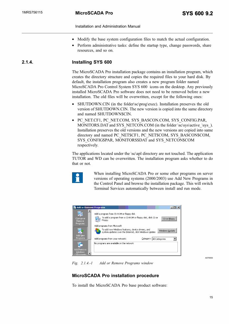
When installing MicroSCADA Pro or some other programs on serverversions of operating systems (2000/2003) use Add New Programs inthe Control Panel and browse the installation package. This will switchTerminal Services automatically between install and run mode.
A070500
Fig. 2.1.4.-1 Add or Remove Programs window
MicroSCADA Pro installation procedure
To install the MicroSCADA Pro base product software:
MicroSCADA Pro
Installation and Administration Manual
SYS 600 9.2SYS 600 9.21MRS756115

1. Restart the computer to remove possible memory resident data.
2. Logon as a user with administrator rights.
3. Double-click the installation icon to start the installation. It is recommended toinstall using Add/Remove Programs from the Control Panel.
4. In the Product Installation dialog the software packages are listed, seeFig. 2.1.4.-2. Select the software packages that you want to install by selectingthe appropriate check box.
A051494
Fig. 2.1.4.-2 Selecting products to be installed.
Program contains MicroSCADA main program and must be installed in SYSPC.
Workstation monitor opening application (mons) is installed for VS and X Monitortypes
Documentation will install documents
In practise, all three packages are installed in the SYS PC. This will allowopening VS monitors locally on SYS PC and reading documents. Workstationpackage is installed on workstation PC if VS/X -type monitors are used.
5. Select the drive in which the application is to be installed. The installationprogram suggests a destination drive for the MicroSCADA Pro installation. IfMicroSCADA Pro has been installed before, the destination drive used in theprevious installation is shown as a default drive. Otherwise, the default drive isC. To select another drive, click Change Drive and choose the drive.
16
SYS 600 9.2SYS 600 9.2 MicroSCADA Pro
Installation and Administration Manual
1MRS756115

17
MicroSCADA Pro must be installed on a disk drive physically locatedin the base system computer. It cannot be installed on a logical diskdrive, for example a network drive.
6. After selecting the components to be installed, click Start. If a previousinstallation of the selected software package is detected, a System Informationdialog is shown.
7. After the System Base Software has been installed, type a password for aMicroSCADA user, see Fig. 2.1.4.-3. The MicroSCADA user is created duringthe installation. It belongs to the Administrator group and it is the user who ownsthe MicroSCADA processes.
The MicroSCADA user performs all references made by the processes. If twobase system computers share resources, the MicroSCADA user should be giventhe same password on both computers. The password can be changed later fromthe MicroSCADA Pro Control Panel.
This user name should not be used for purposes other thanadministration tasks. If the MicroSCADA user already exists due to aprevious installation, the password is not changed.
A051498
Fig. 2.1.4.-3 MicroSCADA User Password dialog
8. After base software is installed, other selected packages are installed.
9. The installation completed dialog is shown when MicroSCADA Pro has beeninstalled.
Installing COM 500i
Existing product COM 500 is included in SYS 600 9.2 or newer as a functionality- COM 500i that is license dependent. COM 500i is a communication gatewayrunning on a MicroSCADA Pro platform. It provides a gateway between processdevices and eight Network Control Centers (NCC). The main tasks of COM 500i aresignal rerouting and protocol conversions. A COM 500i tab is constructed, when theSYS 600 is started for the first time. Select the COM 500i tab from the Tool managerto use the COM 500i functions, see Fig. 2.1.4.-4.
MicroSCADA Pro
Installation and Administration Manual
SYS 600 9.2SYS 600 9.21MRS756115
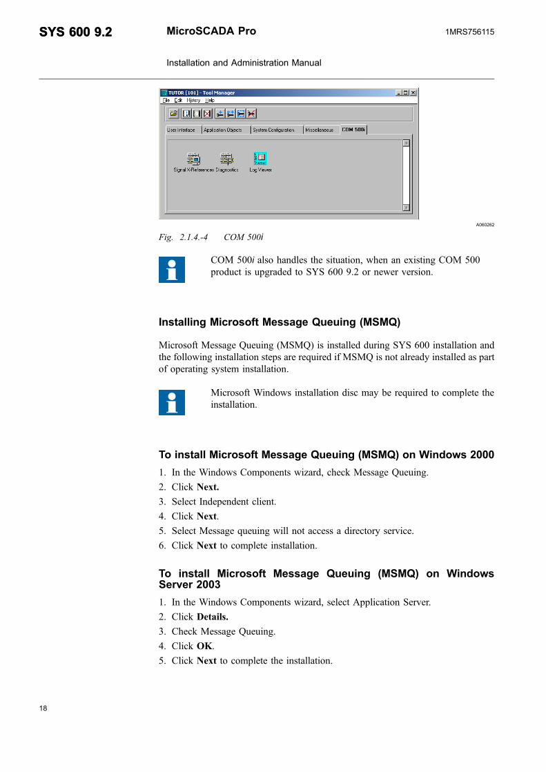
A060262
Fig. 2.1.4.-4 COM 500i
COM 500i also handles the situation, when an existing COM 500product is upgraded to SYS 600 9.2 or newer version.
Installing Microsoft Message Queuing (MSMQ)
Microsoft Message Queuing (MSMQ) is installed during SYS 600 installation andthe following installation steps are required if MSMQ is not already installed as partof operating system installation.
Microsoft Windows installation disc may be required to complete theinstallation.
To install Microsoft Message Queuing (MSMQ) on Windows 2000
1. In the Windows Components wizard, check Message Queuing.
2. Click Next.
3. Select Independent client.
4. Click Next.
5. Select Message queuing will not access a directory service.
6. Click Next to complete installation.
To install Microsoft Message Queuing (MSMQ) on WindowsServer 2003
1. In the Windows Components wizard, select Application Server.
2. Click Details.
3. Check Message Queuing.
4. Click OK.
5. Click Next to complete the installation.
18
SYS 600 9.2SYS 600 9.2 MicroSCADA Pro
Installation and Administration Manual
1MRS756115
19
To install in Terminal Services environment
After program installation, edit MMC500_TS.cmd to match installation drive, thenrun the command file. In a multi user environment like Terminal Server, DynamicLink Libraries (the .DLL files) may fail to open if more than one user attempts touse them. The REGISTER utility allows you to tell the system that a particular .DLLfile should be made available globally to the system and to all users.
A070501
Fig. 2.1.4.-5 Editing command
2.1.5. Verifying SYS 600 installation
During the installation of the MicroSCADA Pro kernel software, two emptyapplications are created. The two applications are named TUTOR and WD.
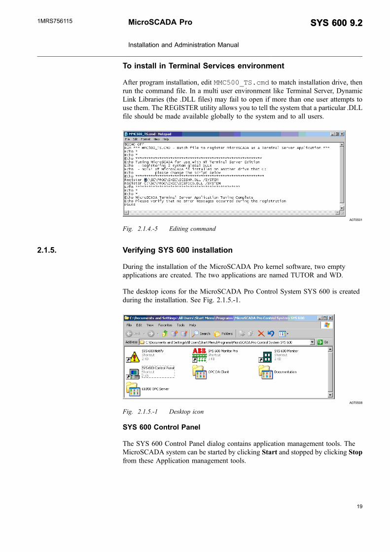
The desktop icons for the MicroSCADA Pro Control System SYS 600 is createdduring the installation. See Fig. 2.1.5.-1.
A070508
Fig. 2.1.5.-1 Desktop icon
SYS 600 Control Panel
The SYS 600 Control Panel dialog contains application management tools. TheMicroSCADA system can be started by clicking Start and stopped by clicking Stopfrom these Application management tools.
MicroSCADA Pro
Installation and Administration Manual
SYS 600 9.2SYS 600 9.21MRS756115

A051222
Fig. 2.1.5.-2 MicroSCADA Control Panel
SYS 600 Notify
The revision information and all the possible error messages that occur during thestart-up and operation of SYS 600 are shown in the Fig. 2.1.5.-3.
A070509
Fig. 2.1.5.-3 SYS 600 Notification Window
SYS 600 Monitor Pro
When an operator wants to supervise an application on a monitor screen of type VSor X, the operator opens a MicroSCADA Pro monitor.
20
SYS 600 9.2SYS 600 9.2 MicroSCADA Pro
Installation and Administration Manual
1MRS756115

21
A070510
Fig. 2.1.5.-4 Monitor Pro Startup Window
SYS 600 Monitor
When an operator wants to supervise an application on a monitor screen of type VSor X, the operator opens a SYS 600 Monitor with the MicroSCADAMonitor dialog.
A051226
Fig. 2.1.5.-5 MicroSCADA monitor dialog
External OPC DA Client
MicroSCADA Pro
Installation and Administration Manual
SYS 600 9.2SYS 600 9.21MRS756115

A070511
Fig. 2.1.5.-6 External OPC DA Client
The shortcut menu for External OPC DA Client Control Panel provides a link toExternal OPC DA tools.
Documentation
This icon links to Status Codes and Operation Manual.
61850 OPC Server
This icon links to Communication Engineering (CET) tool.
A070512
Fig. 2.1.5.-7 CET Tool
Applications
You can add additional applications by using the administration tools accessed fromthe MicroSCADA Control Panel. The MicroSCADA administration tools alsoprovide means for listing and removing applications. When you add an application,the application directories for the new application are created. The startup andinitialization pictures and dialogs are copied to the application directory apl_.
To open the Control MicroSCADA Applications dialog:
22
SYS 600 9.2SYS 600 9.2 MicroSCADA Pro
Installation and Administration Manual
1MRS756115

23
1. Open the MicroSCADA Control Panel by double-clicking the icon.
A070513
Fig. 2.1.5.-8 Control MicroSCADA Applications dialog
2. Click Admin.
3. Click Applications to open the Control MicroSCADA Applications dialog.
In this dialog, it is possible to view, add, prepare and remove the applications.
Adding applications
To add a new application:
1. In the Control MicroSCADA Applications dialog, click Add to open the Addnew application dialog, see Fig. 2.1.5.-9.
A051504
Fig. 2.1.5.-9 Adding new application
MicroSCADA Pro
Installation and Administration Manual
SYS 600 9.2SYS 600 9.21MRS756115

2. Type the name of the application to be created.
3. Click OK.
The new application directory and its subdirectories are created under the \sc\apldirectory. The initialization and startup pictures and dialogs are copied into the pictsubdirectory of the new application.
Preparing applications
When preparing an application, the necessary startup and initialization files arecopied to the application directory. If application is added as described before, it isalso prepared and no further preparations are needed. However, if MicroSCADA isupdated, applications need to be prepared again to use tools properly.
To prepare an application:
1. Open the Control MicroSCADA Applications dialog.
2. Select the application to be prepared.
3. Click Base Tools.
4. Select one of the following options:* Full prepare - copies all the initialization files and pictures to the application
directory. The possible existing files are overwritten.* Limited prepare - to copy initialization files but not the APL_INIT and
APL_START pictures. Use this option if you wish to keep the existingAPL_INIT and APL_START files. For instance, if you have prepared theapplication for LIB 500, you should use Limited prepare.
If LIB 500 is used, prepare the applications for LIB 500.
1. Open the Control MicroSCADA Applications dialog.
2. Select the application to be prepared.
3. Click LIB 500 and refer to the LIB 500 documentation to complete thepreparation.
Removing applications
To remove an existing application:
1. Open the Control MicroSCADA Applications dialog.
2. Select the application to be removed.
3. Click Remove to remove the selected application directory and its sub-directories.
Using this utility physically removes the application from the SYS 600computer file system. Therefore it is important to verify that the backupof the application exists, in case it is required for later use.
24
SYS 600 9.2SYS 600 9.2 MicroSCADA Pro
Installation and Administration Manual
1MRS756115

25
2.2. Local Area Network (LAN)
A local area network (LAN) is a group of computers and associated devices thatshare a common communications line or wireless link. Local area networks are builtwith hardware such as Ethernet cables, network adapters, hubs and managed orunmanaged switches. Wireless LAN and other more advanced LAN hardwareoptions also exist. LANs connect MicroSCADA workstations and SYS 600computers and other supported devices like IEDs using IEC 61850 protocol. Eachindividual device connected to LAN has its own IP address. They are able to accessdata and devices anywhere on the LAN, they can share resources on LAN. Userscan also use the LAN to communicate with each other. There are many differenttypes of LANs. Our scope is on Ethernet and used protocol is TCP/IP. See detailedinstallation instructions from corresponding Windows Operating System manual.
2.2.1. Network interface card
Each computer on the LAN contains a network interface card and software forhandling the card and the used protocols.
Insert the network interface card before installing the Windows operating system.Most computers are equipped with a built-in network interface card. The LANsoftware is installed and configured during the operating system installation.
2.2.2. IP addresses
The communication protocol supported by MicroSCADA is TCP/IP.
Each node or host in a TCP/IP network has an unique identifier, also called an IPaddress. The IP address is composed of four numbers in the range from 0 to 255.The numbers are separated with dots. For example: 192.168.0.1
The smallest LAN can have exactly two computers, a large LAN can accommodatemany thousands of computers. Because every computer on an IP network must havea unique IP address, careful planning of IP addresses to the whole system isimportant. You should remember to take care of the future needs in address areaswhen planning large networks.
There are some special IP addresses. 127.0.0.1 is known as the loopback addressand it always refers to the local computer. Hostname used for the address is'localhost'.
Use static addressing in MicroSCADA networks.
The IP addresses of the MicroSCADA Pro base system and workplaces mustcomply with the addresses of other nodes on the network. Consult the local areanetwork administrator for valid IP addresses and other LAN configuration issues.This document does not include planning guide for TCP/IP networks. You can findthese guides from Microsoft or other Internet sites.
MicroSCADA Pro
Installation and Administration Manual
SYS 600 9.2SYS 600 9.21MRS756115

2.2.3. Host names
During Windows installation:
1. Type the computer name for the NETBIOS protocol so that the computer isrecognized on the LAN. The computer's name is not the same as the host nameused by TCP/IP. The host name is given during the TCP/IP protocolconfiguration.
2. Read the computer's host name and IP address by typing: ipconfig /all in aCommand Prompt window. It is also possible to verify the settings from theNetwork Tool in the Control Panel.
To be able to use host names in the communication front-end computers, the namesto be recognized have to be defined in a host table on the computer. The host tablemaps the host name to an IP address. On most Windows systems it is at C:\Windows\System32\Drivers\Etc\Hosts. An example of a HOSTS file is listed below:
# Copyright (c) 1993-1999 Microsoft Corp.## This is a sample HOSTS file used by Microsoft TCP/IP for Windows.## This file contains the mappings of IP addresses to host names. Each# entry should be kept on an individual line. The IP address should# be placed in the first column followed by the corresponding host name.# The IP address and the host name should be separated by at least one# space.## Additionally, comments (such as these) may be inserted on individual# lines or following the machine name denoted by a '#' symbol.## For example:## 102.54.94.97 rhino.acme.com # source server# 38.25.63.10 x.acme.com # x client host
The following is an example of a host table. Here each node has two names, one inlower case letters and one in upper case letters. The items in a host table areseparated by spaces or tabs.
127.0.0.1 localhost
10.58.125.45 apassi APASSI
10.58.125.46 ws1 WS1
10.58.125.47 ws2 WS2
10.58.125.48 fe1 FE1
There are, however, other mechanisms such as DNS that can be used. Consult yournetwork administrator for information on solutions applied to your network.
2.2.4. Configuring SYS 600 for LAN
In the base systems connected to a LAN, define a LIN object of LAN. One object isenough for all LAN connections.
#CREATE LIN:V = LIST(- ;Link to other SYS or LAN frontend (requires TCP/IP)LT = "LAN") ;Link type
#CREATE LIN1:B = %LIN
#CREATE NOD:V = LIST(- ;Node for LAN frontend or SYSLI = 1,-NN = "10.58.125.131",-DI = 10,-DT = 30,-
26
SYS 600 9.2SYS 600 9.2 MicroSCADA Pro
Installation and Administration Manual
1MRS756115

27
SA = 232)#CREATE NOD32:B = %NOD
#CREATE NOD:V = LIST(- ;Node for LAN frontend or SYSLI = 1,-NN = "System2",-DI = 10,-DT = 30,-SA = 230)
#CREATE NOD30:B = %NOD
2.2.5. Verifying the LAN communication
Use the ping utility to test the connectivity on the LAN and determine if a host isavailable and active. The syntax is: ping host where 'host' is the computer's IPaddress or node name on the network. If the computer responds, a message isproduced with some diagnostic information.
A070514
Fig. 2.2.5.-1 Testing LAN Connectivity
Example:
Ping 192.10.0.210
Reply from 192.10.0.210: bytes = 32 time < 10ms TTL 255
The typical reply time is below 10ms. If the reply time exceeds 50 ms on normal 10/100Mb/s Wired or Fibre Optic Network, it is recommended to check the LANcommunication equipment.
2.3. Installing workplaces
2.3.1. Installing Terminal Services
Terminal Services is a component of Microsoft Windows (both server and clientversions) that allows a user to access applications and data stored on a remotecomputer over a network. This feature is needed to be able to openMicroSCADA Pro FrameWindow –type pictures on workstations.
MicroSCADA Pro
Installation and Administration Manual
SYS 600 9.2SYS 600 9.21MRS756115

A050195
Fig. 2.3.1.-1 Principles of Terminal Server based computing
Server-based computing
With server-based computing it is possible to deploy, manage, support and executeapplications completely on a server. The client devices, whether “fat or thin”, haveinstant access to it without application rewrites or downloads.
Components of server-based computing
Server-based computing relies on three critical components:
1. A multiuser operating system that allows multiple concurrent users to log on andrun applications in separate, protected sessions on a single server.
2. A remote presentation services architecture capable of separating theapplication's logic from its user interface, in such a way that only keystrokes,mouse clicks, and screen updates travel the network.
3. The Terminal Server product consists of four components: the Windows Servermultiuser core, the Remote Display Protocol, the Windows-based client softwareand enhanced system administration tools.
Terminal Server: A multiuser server core that provides the ability to hostmultiple, simultaneous client sessions on Windows Server 4.0 (Terminal ServerEdition) and on later versions of Windows Server (Windows Server 2000, WindowsServer 2003).
Remote Display Protocol (RDP): A key component of Terminal Server is theprotocol, which allows a client to communicate with the Terminal Server over thenetwork. It is a multichannel protocol tuned for high-bandwidth enterpriseenvironments. Furthermore, it supports three levels of encryption.
Terminal Server Client: The client software presenting or displaying the 32-bitWindows user interface on a range of desktop hardware.
28
SYS 600 9.2SYS 600 9.2 MicroSCADA Pro
Installation and Administration Manual
1MRS756115

29
Administration Tools: In addition to all the familiar Windows Serveradministration tools, Terminal Server adds the Terminal Server License Manager,Terminal Server Client Creator, Terminal Server Client Connection Configurationand Terminal Server Administration tools for managing the client sessions. Thereare two new objects, Session and User, which are also added to the PerformanceMonitor to allow tuning of the server in a multiuser environment.
2.3.2. Terminal Server system requirements
The Terminal Server system requirements are as follows.
Operating system:
* Microsoft Windows 2000 Server or* Microsoft Windows Server 2003 Standard Edition
Base Requirements:
* 32-bit x86 microprocessor (such as Intel PentiumIII or higher)* 1024x768 or higher resolution monitor, 256 colors* One or more hard disks, with 1GB minimum of free hard disk space* 256 MB of RAM, plus 10 MB for each typical user who is connecting* Transmission Control Protocol/Internet Protocol (TCP/IP)* CD-ROM drive or network access for installation
Processor and Memory Requirements:
Processor and memory requirements scale linearly up to four processors. Themaximum memory supported is 4 GB.
Other Peripherals:
Hard disk throughput also affects the performance of the system. For the highestdisk performance, consider using a SCSI RAID controller. The RAID (RedundantArray of Independent Disks) controllers place data on multiple disk drivesautomatically and can therefore increase disk performance and improve datareliability.
Although the Remote Desktop Protocol used with Terminal Server causes negligiblenetwork load, a high-performance network interface card (NIC) is recommended.This is particularly important, if many users require access to data stored on networkservers or run client/server applications.
If a multiport asynchronous communications adapter is installed for supporting dial-in users, be sure to use an intelligent (microprocessor-based) adapter to reduceinterrupt overhead and increase throughput.
Client System:
MicroSCADA Pro
Installation and Administration Manual
SYS 600 9.2SYS 600 9.21MRS756115

A Terminal Server Client can be used on a client PC to access a Terminal Serverusing the TCP/IP protocol from a network or by connecting via a Remote AccessService (RAS) connection.
The minimum requirements for the 32-bit Terminal Server Client are:
* Personal computer with an x86 compatible processor, Pentium or higher.* The Client is available on any Windows operating system. It is included or can
be downloaded to older Windows versions.* 1024x768 or higher resolution video adapter, min. 256 colors.* Network interface card (NIC) using the Microsoft TCP/IP protocol.* Microsoft serial mouse or 100 percent compatible.
Windows XP or Windows 2000 Professional does not contain TerminalServices, but only the RDP Client. Terminal Services is a feature ofWindows 2000/2003 Servers.
2.3.3. Licensing service installation
To install the license service:
1. Choose Terminal Server Licensing during product setup, or at any time click theAdd or Remove Programs icon on Control Panel.
2. Click Add/Remove Windows Components.
A051187
Fig. 2.3.3.-1 Add/Remove Components, Terminal Services Licensing
In Windows Server 2003, the licensing service can be installed on a workgroupbased server, a member server or a domain controller.
30
SYS 600 9.2SYS 600 9.2 MicroSCADA Pro
Installation and Administration Manual
1MRS756115
31
During the installation of the Terminal Server Licensing service, you need to choosebetween the following modes of the license server:
* Your entire enterprise (enterprise license server)* Your domain or workgroup (domain/workgroup license server)
Normally, your domain or workgroup is used. In this scenario, a license server isautomatically discovered by any terminal server within the same subnet as thelicense server.
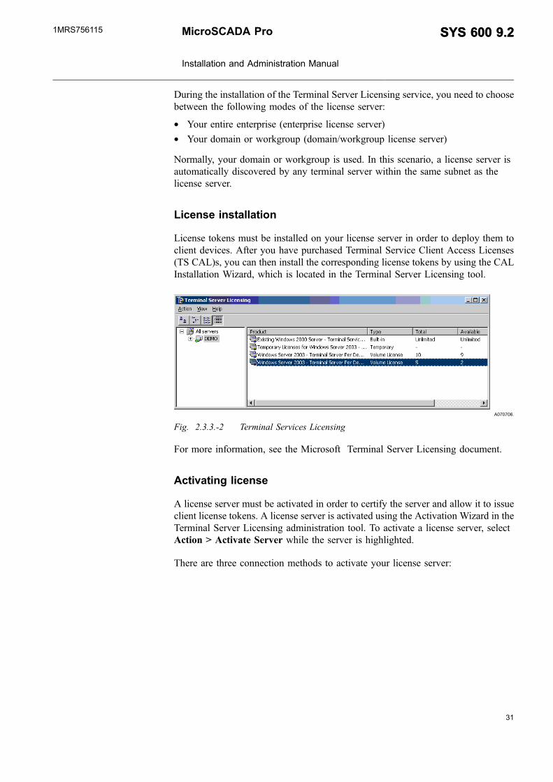
License installation
License tokens must be installed on your license server in order to deploy them toclient devices. After you have purchased Terminal Service Client Access Licenses(TS CAL)s, you can then install the corresponding license tokens by using the CALInstallation Wizard, which is located in the Terminal Server Licensing tool.
A070706.
Fig. 2.3.3.-2 Terminal Services Licensing
For more information, see the Microsoft Terminal Server Licensing document.
Activating license
A license server must be activated in order to certify the server and allow it to issueclient license tokens. A license server is activated using the Activation Wizard in theTerminal Server Licensing administration tool. To activate a license server, selectAction > Activate Server while the server is highlighted.
There are three connection methods to activate your license server:
MicroSCADA Pro
Installation and Administration Manual
SYS 600 9.2SYS 600 9.21MRS756115

* Internet (Automatic): The quickest and easiest way to activate and installlicenses, which is also recommended by Microsoft. This method requiresInternet connectivity from the device running the Terminal Server Licensingadmin tool. Internet connectivity is not required from the license server itself.The internet method uses TCP/IP (TCP port 443) to connect directly to theClearinghouse.
* Web: The Web method should be used when the device running the TerminalServer Licensing admin tool does not have internet connectivity, but you do haveaccess to the Web by means of a Web browser from another computer. The URLfor the Web method is displayed in the Activation Wizard.
* Phone: The phone method allows you to talk to a Microsoft Customer ServiceRepresentative to complete the activation or license installation transactions. Theappropriate telephone number is determined by the country/region you choose inthe Activation Wizard and is displayed by the wizard.
A license server must be activated only once. While waiting to complete theactivation or license token installation processes, your license server can issuetemporary tokens for clients that allow Terminal Server Licensing.
Purchasing license
The process for purchasing TS CALs for Windows Server 2003 remains the same asfor purchasing other Microsoft Client Access licenses. Customers might purchasethese licenses by obtaining a Microsoft License Pack (MLP), Microsoft OpenLicense, or through one of Microsoft's volume licensing programs, such asMicrosoft Select.
2.3.4. Installing Windows 2000/2003 Terminal Services
To install Windows 2000/2003 Terminal Services:
1. Open the Control Panel.
2. Double-click the Add/Remove Programs icon. The Add/Remove Programsdialog is displayed.
3. Click Add/Remove Windows Components on the left pane. The WindowsComponents Wizard is displayed.
4. Scroll down the list to find Terminal Services and choose it by selecting a checkbox on the left of it. If you click Details, you will see that there are two sub-components:* Client Creator Files* Enable Terminal Services. See Fig. 2.3.4.-1.
32
SYS 600 9.2SYS 600 9.2 MicroSCADA Pro
Installation and Administration Manual
1MRS756115

33
A050088
Fig. 2.3.4.-1 Subcomponents of Terminal Services dialog
5. The next dialog informs you to install Terminal Services to run in one of the twomodes:* Remote Administration or* Application Server.
The Application mode is required. This also requires the Terminal ServicesLicensing service to be installed. A Terminal Services Client Access Licenseis also required for non-Windows 2000 Professional clients.
6. After selecting the mode, click Next to continue.
The following two dialogs concern the applications. In the first dialog, you candetermine how much you would like to restrict the users from accessing theregistry. Some applications store user settings in the registry, and will thereforeneed more permission to it than others.
7. Select Windows 2000 Users. A warning dialog may appear even if everything isdone correctly. After that, the file copying progress dialog is displayed.
8. Click Finish to finish the installation.
9. Restart the computer.
Windows Server 2003
When you install Windows Server 2003, you are not prompted to install TerminalServices. You can only enable or disable connections to the computer.
You can use Add or Remove Programs to install Terminal Server.
MicroSCADA Pro
Installation and Administration Manual
SYS 600 9.2SYS 600 9.21MRS756115

A070708
Fig. 2.3.4.-2 Installing Terminal Services
Terminal Server Licensing is a required component that licenses clients on aterminal server. You must install Terminal Server Licensing or your terminal serverwill stop accepting connections from unlicensed clients 120 days from the date ofthe first client logon. For small deployments, it is acceptable to install both theTerminal Server and Terminal Server Licensing service on the same physicalcomputer. For larger deployments, it can be installed on a separate server.
Managing Terminal Services Users
Each user who logs on to a Terminal Services session must have a user accounteither on the server or in a domain on the network that the server is on. The TerminalServices user account contains additional information about the user.
Windows Server 2003 family operating systems contain a built-in User group calledRemote Desktop Users, which is used to manage Terminal Services users.
When you install one of the Windows Server 2003 operating systems, the RemoteDesktop Users group is one of the built-in user groups on your computer. Membersof this group have the same access as members of the Users group, but they have theadditional ability to log on remotely to the computer. By default, this group is notpopulated when you install Terminal Server. You must choose the users and groupsthat you want to have permission to log on remotely to the terminal server, andmanually add them to the Remote Desktop Users group.
To add users to the Remote Desktop Users group:
1. Open Computer Management.
2. In the console tree, click the Local Users and Groups node.
3. In the details pane, double-click the Groups folder.
4. Double-click Remote Desktop Users, and then click Add.
34
SYS 600 9.2SYS 600 9.2 MicroSCADA Pro
Installation and Administration Manual
1MRS756115

35
5. On the Select Users dialog box, click Locations to specify the search location.
6. Click Object Types to specify the types of objects you want to search for.
7. Type the name you want to add in the Enter the object names toselect (examples): box.
8. Click Check Names.
9. When the name is located, click OK.
In the server computer, client users were previously grantedAdministrator rights to get access to the MicroSCADA and its relatedtools from the client computer. The following now describes analternative solution.
By default, a Remote Desktop Users group is available in the operatingsystem. The client login names should be defined to belong to thisRemote Desktop Users group. After this, the rights to Modify Accessto the MicroSCADA directory, i.e.<drive>\sc should be granted.
A070740
Fig. 2.3.4.-3 Access rights for MicroSCADA users
2.3.5. Installing Terminal Server Client
Windows 2000
There are two methods to install the Terminal Server Client.
MicroSCADA Pro
Installation and Administration Manual
SYS 600 9.2SYS 600 9.21MRS756115

The Client Creator can be used to create disks for installing the client software on auser's computer. You can use these disks to distribute the appropriate TerminalServices Client to each user.
One of the directories created in Terminal Services installation is WINNT\system32\clients\tsclient.
By sharing this directory as read-only, you can install the Terminal Server Clientover the network without using discs. This is done simply by running setup.exefrom the net\win32 directory.
Windows Server 2003/XP Professional computers
The Client is installed as default.
The Terminal Services Client, called the Remote Desktop Connection (RDC),provides substantial improvements over previous releases, including greaterfunctionality through a simplified user interface.
Remote Desktop Connection for Windows XP (Terminal Services Client 6.0) isavailable from Microsoft site (see KB925876). This will give some new usefulfeatures, for example, it is possible to use large two monitor displays onworkstations.
This version of Remote Desktop Connection (Terminal Services Client 6.0) can beinstalled on client computers running Windows XP Service Pack 2. It can be used toconnect to terminal servers or remote desktops running earlier versions of Windows,but the new features are available only when the remote computer is runningWindows Vista or Windows Server, code name "Longhorn."
2.3.6. Remote Display Protocol (RDP) Client
To open the Remote Desktop Connection (RDP) Client select Startup >Accessories > Communications > Remote Desktop Connection. See Fig. 2.3.6.-1below.
A051130
Fig. 2.3.6.-1 Opening the Remote Desktop Connection
Customizing the Remote Connection
To change the various options for configuring the remote connection, a propertysheet with tabs shows the controls for
36
SYS 600 9.2SYS 600 9.2 MicroSCADA Pro
Installation and Administration Manual
1MRS756115
37
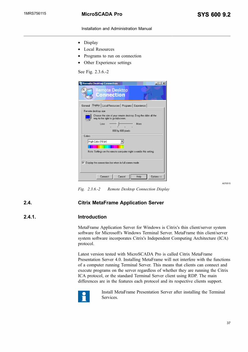
* Display* Local Resources* Programs to run on connection* Other Experience settings
See Fig. 2.3.6.-2
A070515
Fig. 2.3.6.-2 Remote Desktop Connection Display
2.4. Citrix MetaFrame Application Server
2.4.1. Introduction
MetaFrame Application Server for Windows is Citrix's thin client/server systemsoftware for Microsoft's Windows Terminal Server. MetaFrame thin client/serversystem software incorporates Citrix's Independent Computing Architecture (ICA)protocol.
Latest version tested with MicroSCADA Pro is called Citrix MetaFramePresentation Server 4.0. Installing MetaFrame will not interfere with the functionsof a computer running Terminal Server. This means that clients can connect andexecute programs on the server regardless of whether they are running the CitrixICA protocol, or the standard Terminal Server client using RDP. The maindifferences are in the features each protocol and its respective clients support.
Install MetaFrame Presentation Server after installing the TerminalServices.
MicroSCADA Pro
Installation and Administration Manual
SYS 600 9.2SYS 600 9.21MRS756115

2.4.2. System requirements
* Microsoft Windows 2000 Server and Service Pack 4.0 (or later) or* Microsoft Windows Server 2003 and Windows Server 2003 SP1* Microsoft NET Framework version 1.1* Java Runtime Enviroment (JRE) version 1.4.1_02 (or later)* ASP.NET (Microsoft component)
2.4.3. Installing Citrix MetaFrame Presentation Server 4.0 system
2.4.3.1. Windows components installation
To install the Windows component:
1. From the Control Panel, go to Add or Remove Programs and select Add orRemove Windows Components.
A070516
Fig. 2.4.3.1.-1 Windows Component Wizard
2. Select Application Server and click Details.
3. Select Application Server Console, if not yet checked and ASP.NET.
38
SYS 600 9.2SYS 600 9.2 MicroSCADA Pro
Installation and Administration Manual
1MRS756115

39
A070517
Fig. 2.4.3.1.-2 Application Server dialog
4. Click OK in the Application Server dialog and click Next in the WindowsComponents Wizard.
5. Click Finish.
2.4.3.2. Get Citrix license file from internet
1. Go to http://mycitrix.com. The Citrix Login page is displayed.
A070518
Fig. 2.4.3.2.-1 Citrix Login Window
2. Type Login ID, Password and click Login.
3. Click Licensing.
4. Click Citrix Activation System (CAS).
5. Click Activation of licenses. Follow the rules for Citrix License Activation.
MicroSCADA Pro
Installation and Administration Manual
SYS 600 9.2SYS 600 9.21MRS756115
2.4.3.3. Installation and configuration of MetaFrame Access Suitelicensing
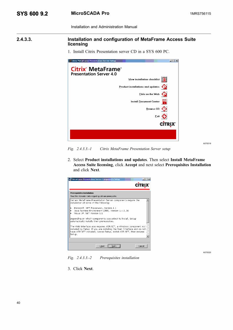
1. Install Citrix Presentation server CD in a SYS 600 PC.
A070519
Fig. 2.4.3.3.-1 Citrix MetaFrame Presentation Server setup
2. Select Product installations and updates. Then select Install MetaFrameAccess Suite licensing, click Accept and next select Prerequisites Installationand click Next.
A070520
Fig. 2.4.3.3.-2 Prerequisites installation
3. Click Next.
40
SYS 600 9.2SYS 600 9.2 MicroSCADA Pro
Installation and Administration Manual
1MRS756115

41
A070521
Fig. 2.4.3.3.-3 Component selection
4. Click Next.
MicroSCADA Pro
Installation and Administration Manual
SYS 600 9.2SYS 600 9.21MRS756115

A070522
Fig. 2.4.3.3.-4 Citrix MetaFrame Access Suite licensing setup
5. Click Next and then accept Destination Folder by clicking Next. Accept theselected features and click Next.
42
SYS 600 9.2SYS 600 9.2 MicroSCADA Pro
Installation and Administration Manual
1MRS756115
43
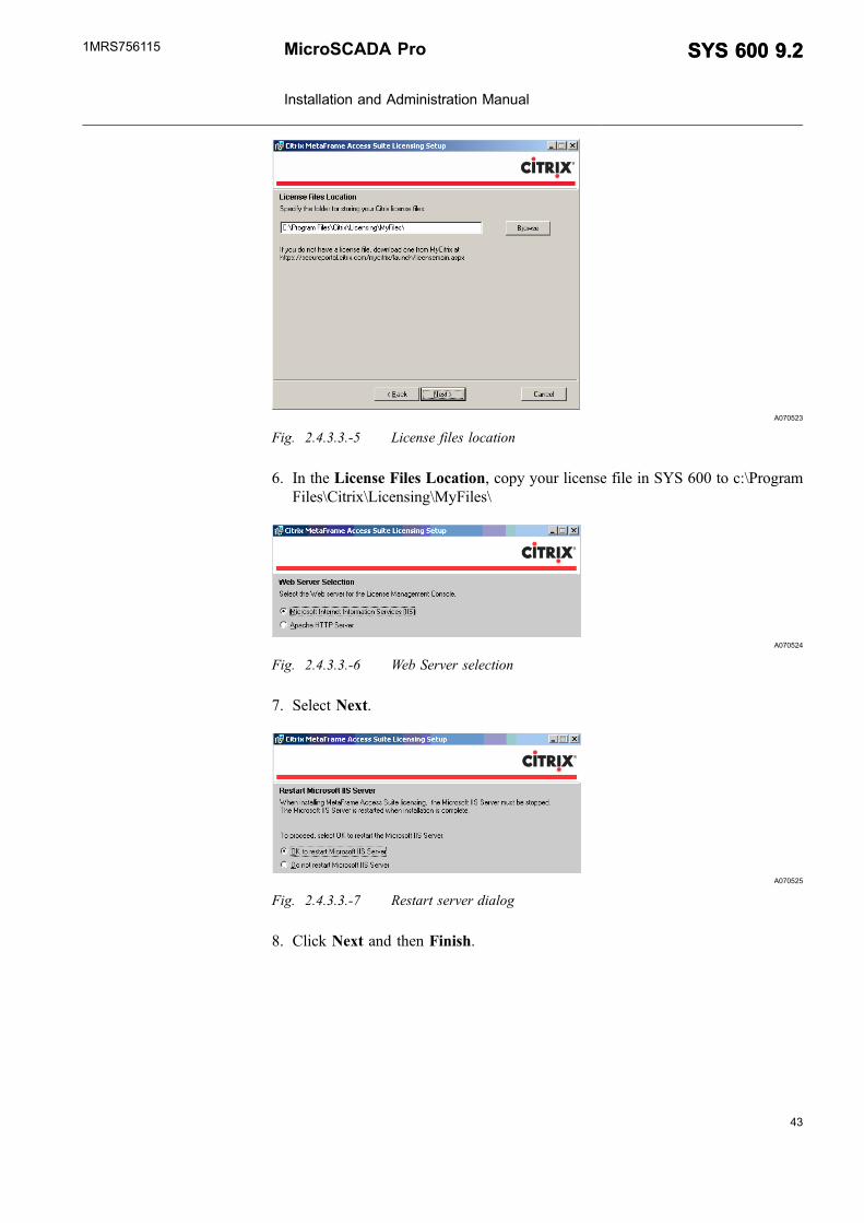
A070523
Fig. 2.4.3.3.-5 License files location
6. In the License Files Location, copy your license file in SYS 600 to c:\ProgramFiles\Citrix\Licensing\MyFiles\
A070524
Fig. 2.4.3.3.-6 Web Server selection
7. Select Next.
A070525
Fig. 2.4.3.3.-7 Restart server dialog
8. Click Next and then Finish.
MicroSCADA Pro
Installation and Administration Manual
SYS 600 9.2SYS 600 9.21MRS756115

2.4.3.4. Install MetaFrame Presentation Server 4.0 and its components
1. Click Install MetaFrame Presentation Server 4.0 and its components asshown in the figure below.
A070526
Fig. 2.4.3.4.-1 MetaFrame Presentation Server and components installation dialog
2. Accept the license agreement and continue.
A070527
Fig. 2.4.3.4.-2 License agreement
A070528
Fig. 2.4.3.4.-3 Component Selection for MetaFrame Presentation Server
3. Click Next.
44
SYS 600 9.2SYS 600 9.2 MicroSCADA Pro
Installation and Administration Manual
1MRS756115

45
A070529
Fig. 2.4.3.4.-4 Warning dialog
4. Follow the Components Setup messages. In most cases there is no need changedefault setup.
5. The following is an example setting when joining a Farm.
A070530
Fig. 2.4.3.4.-5 Server farm window
Farm name: SCADA
MicroSCADA Pro
Installation and Administration Manual
SYS 600 9.2SYS 600 9.21MRS756115

A070531
Fig. 2.4.3.4.-6 Create Server farm window
6. Click Next.
A070532
Fig. 2.4.3.4.-7 Assigning credentials
7. Click Next.
46
SYS 600 9.2SYS 600 9.2 MicroSCADA Pro
Installation and Administration Manual
1MRS756115

47
A070533
Fig. 2.4.3.4.-8 Licensing settings
8. Click Next.
A070534
Fig. 2.4.3.4.-9 Configuring Citrix XML Service Port
The installation summary is displayed at the end.
MicroSCADA Pro
Installation and Administration Manual
SYS 600 9.2SYS 600 9.21MRS756115

A070535
Fig. 2.4.3.4.-10 Installation summary window
Citrix will set Only Launch Published Applications selection on bothconnection types, ICA and RDP. Installing Citrix MetaFrame affectsalso Terminal Services RDP! You have to deselect Only LaunchPublished Applications.
To do so:
1. Go to All Programs -> Citrix -> Administration Tools -> Citrix ConnectionConfiguration Tool
A070536
Fig. 2.4.3.4.-11 Citrix Client configuration tool
2. In the Citrix Connection Configuration, right click “..rdp-tcp..” and click Edit.
48
SYS 600 9.2SYS 600 9.2 MicroSCADA Pro
Installation and Administration Manual
1MRS756115

49
A070537
Fig. 2.4.3.4.-12 Citrix Connection Configuration
3. Deselect Only Launch Published Applications. Do the same procedure for ica-tcp also.
A070538
Fig. 2.4.3.4.-13 Advanced connection settings
2.4.4. Publishing applications
It is MetaFrame Presentation Server's integral function to make applications andtheir content available to users. If you are logged into a certain server farm, usePresentation Server Console to publish applications on any server in the server farm.You do not have to run Presentation Server Console from the same MetaFramePresentation Server, where the applications are installed. The server or servers, thathost the published applications, has to be a server farm member.
To publish an application:
MicroSCADA Pro
Installation and Administration Manual
SYS 600 9.2SYS 600 9.21MRS756115

1. Open the Presentation Server console.
A070720
Fig. 2.4.4.-1 Launching Presentation Server console
A070721
Fig. 2.4.4.-2 Authentication window
2. Click Cancel.
A070722
Fig. 2.4.4.-3 Logon window
3. Enter Password and click OK.
50
SYS 600 9.2SYS 600 9.2 MicroSCADA Pro
Installation and Administration Manual
1MRS756115
51
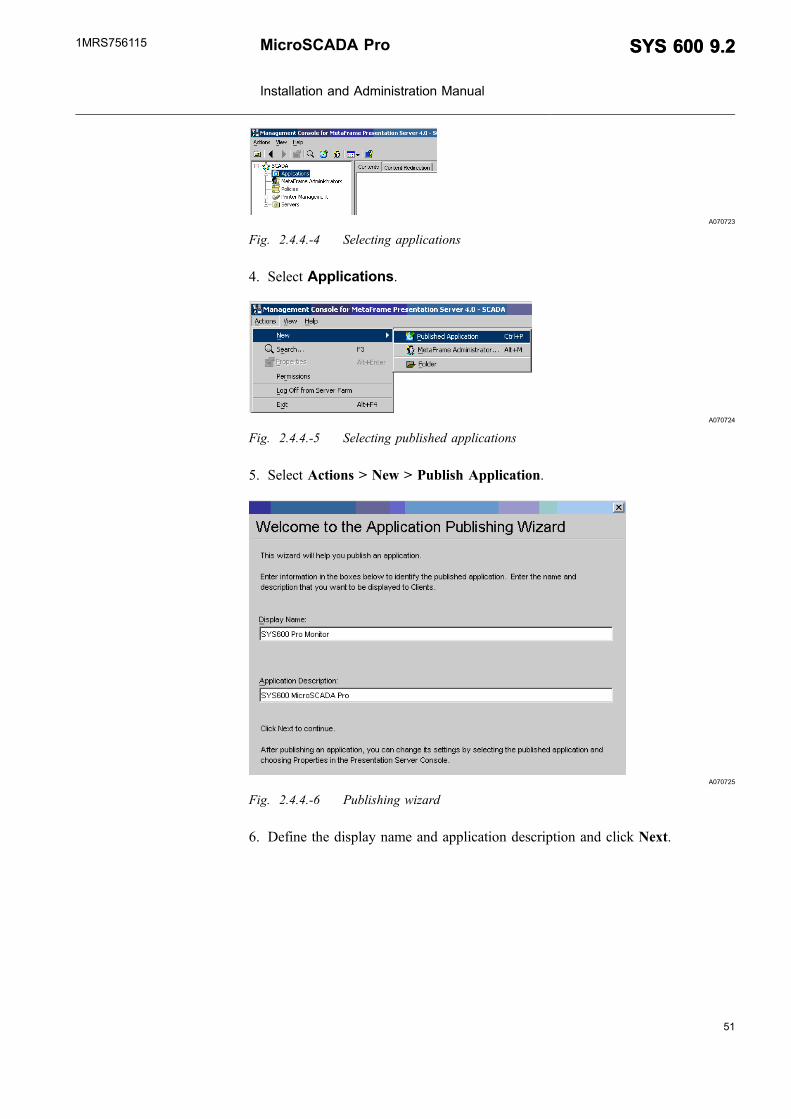
A070723
Fig. 2.4.4.-4 Selecting applications
4. Select Applications.
A070724
Fig. 2.4.4.-5 Selecting published applications
5. Select Actions > New > Publish Application.
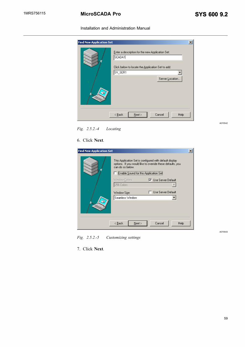
A070725
Fig. 2.4.4.-6 Publishing wizard
6. Define the display name and application description and click Next.
MicroSCADA Pro
Installation and Administration Manual
SYS 600 9.2SYS 600 9.21MRS756115

A070726
Fig. 2.4.4.-7 Selecting application dialog
7. Browse to “FrameWindow.exe”
A070727
Fig. 2.4.4.-8 Command line
8. Click Next.
52
SYS 600 9.2SYS 600 9.2 MicroSCADA Pro
Installation and Administration Manual
1MRS756115

53
A070728
Fig. 2.4.4.-9 Program neighborhood settings
9. Click Next.
A070729
Fig. 2.4.4.-10 Application appearance
10.Click Next.
MicroSCADA Pro
Installation and Administration Manual
SYS 600 9.2SYS 600 9.21MRS756115

A070730
Fig. 2.4.4.-11 Client requirements
11.Click Next.
A070731
Fig. 2.4.4.-12 Configuring access control
12.Click Next.
54
SYS 600 9.2SYS 600 9.2 MicroSCADA Pro
Installation and Administration Manual
1MRS756115

55
A070732
Fig. 2.4.4.-13 Specifying servers
13.Add server and click Next.
A070733
Fig. 2.4.4.-14 Specifying users
14.Click Finish and exit from the Management Console.
MicroSCADA Pro
Installation and Administration Manual
SYS 600 9.2SYS 600 9.21MRS756115

2.5. ICA Workstation Installation
2.5.1. Installation of “Program Neighborhood”-Client
1. Install Citrix Presentation server CD (Components Disk ) to Workstation.
A070715
Fig. 2.5.1.-1 Citrix MetaFrame Presentation Server Clients
2. Select MetaFrame Presentation Server Clients.
3. Select Install MetaFrame Presentation Server Client for Windows, nextaccept License Agreement and continue.
A070716
Fig. 2.5.1.-2 Selecting client
4. Click Next.
A070717
Fig. 2.5.1.-3 Entering client name
5. Click Next.
56
SYS 600 9.2SYS 600 9.2 MicroSCADA Pro
Installation and Administration Manual
1MRS756115

57
A070718
Fig. 2.5.1.-4 Using Local Name and Password
6. Click Next.
A070719
Fig. 2.5.1.-5 Program Neighborhood Options
7. Click Next to begin installation. After successful installation, click Finish.
2.5.2. Adding a new Application Set
A basic ICA client limits the connection type choices to just custom ICAconnections.
With custom ICA desktop or application, the user connects to the Citrix server andreceives either a full desktop on the server or runs a particular published application.
With the full version of the Citrix ICA client, you will get Program Neighborhoodfunctionality. The Citrix Program Neighborhood enables to make a connection to apublished application set. By setting up an application set, a user sees a set ofapplication icons based on what applications are published for him.
To access published application “FrameWindow.exe” from the workstation:
1. Browse to Program Neighbourhood and doubleclick.
A070539
Fig. 2.5.2.-1 Start Menu
2. Select Find New Application Set.
MicroSCADA Pro
Installation and Administration Manual
SYS 600 9.2SYS 600 9.21MRS756115

A070540
Fig. 2.5.2.-2 Find new application set
3. Click Next.
4. Type the name SCADA1, click Server Location, add address and click OK.
A070541
Fig. 2.5.2.-3 New application set
5. Select the name of server from the drop-down list. Note that MicroSCADA Prois running on SV_SER1.
58
SYS 600 9.2SYS 600 9.2 MicroSCADA Pro
Installation and Administration Manual
1MRS756115
59
A070542
Fig. 2.5.2.-4 Locating
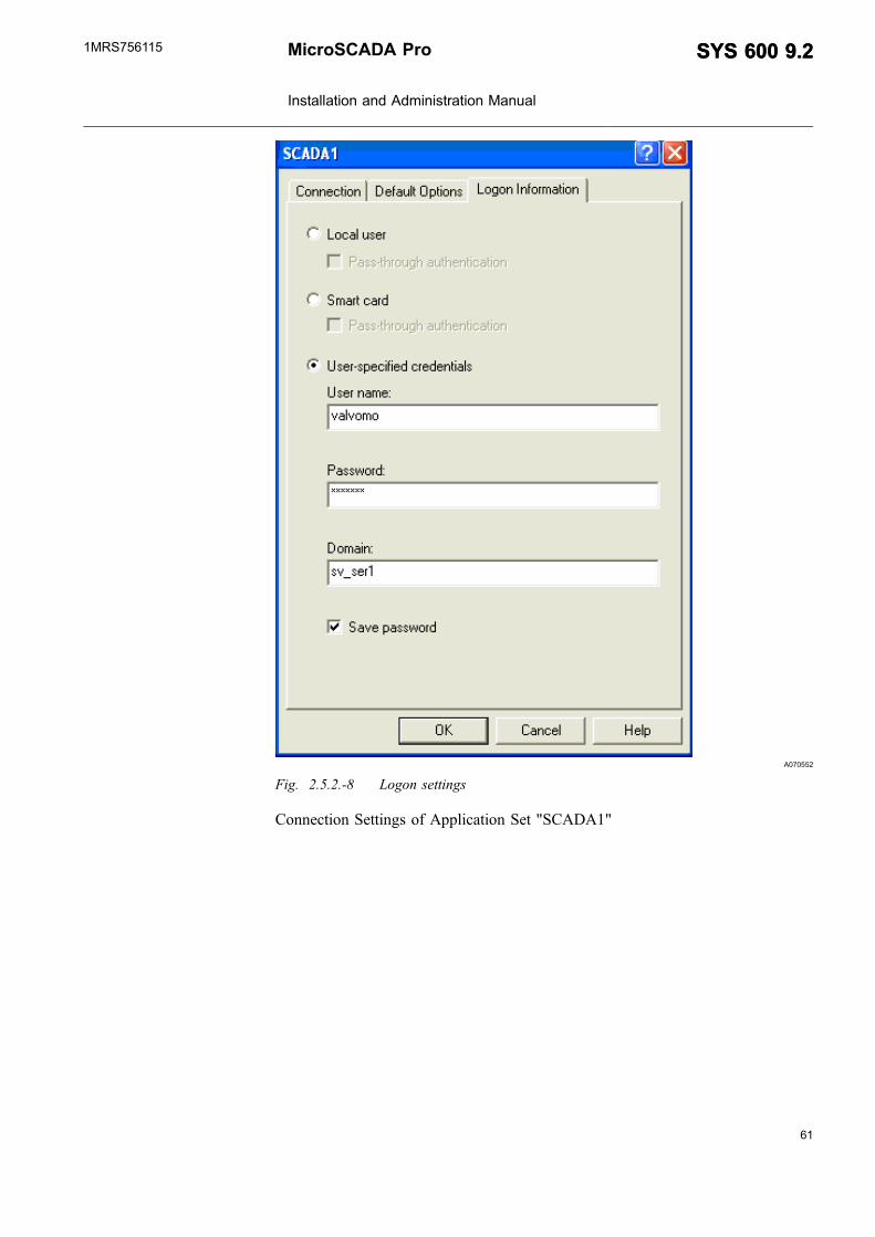
6. Click Next.
A070543
Fig. 2.5.2.-5 Customizing settings
7. Click Next.
MicroSCADA Pro
Installation and Administration Manual
SYS 600 9.2SYS 600 9.21MRS756115

A070544
Fig. 2.5.2.-6 Setup successful message
8. Click Finish.
9. Click Find New Application Set in the Citrix Program Neighborhood window.
A070545
Fig. 2.5.2.-7 Citrix Program Neighborhood Window
Logon settings of Application Set “SCADA1” User “valvomo” of SV_SER1 is amember of Remote desktop users.
60
SYS 600 9.2SYS 600 9.2 MicroSCADA Pro
Installation and Administration Manual
1MRS756115
61
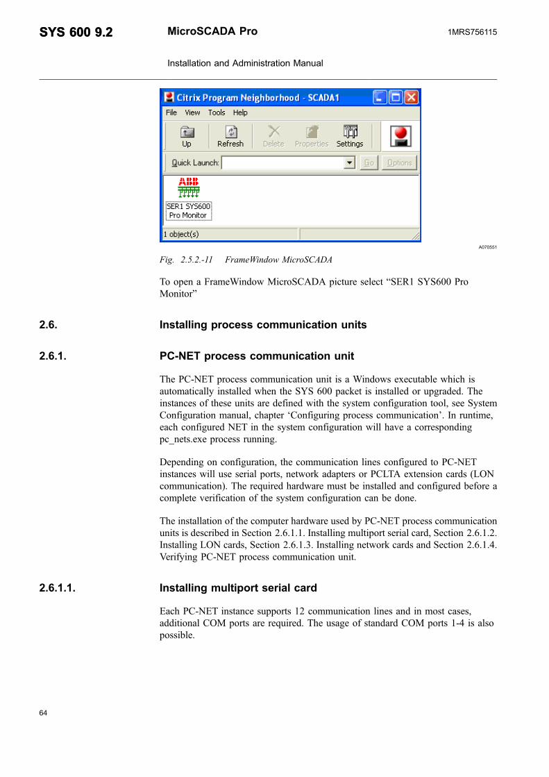
A070552
Fig. 2.5.2.-8 Logon settings
Connection Settings of Application Set "SCADA1"
MicroSCADA Pro
Installation and Administration Manual
SYS 600 9.2SYS 600 9.21MRS756115

A070549
Fig. 2.5.2.-9 Connection settings
Default Options of Application Set “SCADA1”
62
SYS 600 9.2SYS 600 9.2 MicroSCADA Pro
Installation and Administration Manual
1MRS756115

63
A070550
Fig. 2.5.2.-10 Default options
When selecting Application Set “SCADA1” then following folder appears.
MicroSCADA Pro
Installation and Administration Manual
SYS 600 9.2SYS 600 9.21MRS756115
A070551
Fig. 2.5.2.-11 FrameWindow MicroSCADA
To open a FrameWindow MicroSCADA picture select “SER1 SYS600 ProMonitor”
2.6. Installing process communication units
2.6.1. PC-NET process communication unit
The PC-NET process communication unit is a Windows executable which isautomatically installed when the SYS 600 packet is installed or upgraded. Theinstances of these units are defined with the system configuration tool, see SystemConfiguration manual, chapter ‘Configuring process communication’. In runtime,each configured NET in the system configuration will have a correspondingpc_nets.exe process running.
Depending on configuration, the communication lines configured to PC-NETinstances will use serial ports, network adapters or PCLTA extension cards (LONcommunication). The required hardware must be installed and configured before acomplete verification of the system configuration can be done.
The installation of the computer hardware used by PC-NET process communicationunits is described in Section 2.6.1.1. Installing multiport serial card, Section 2.6.1.2.Installing LON cards, Section 2.6.1.3. Installing network cards and Section 2.6.1.4.Verifying PC-NET process communication unit.
2.6.1.1. Installing multiport serial card
Each PC-NET instance supports 12 communication lines and in most cases,additional COM ports are required. The usage of standard COM ports 1-4 is alsopossible.
64
SYS 600 9.2SYS 600 9.2 MicroSCADA Pro
Installation and Administration Manual
1MRS756115

65
The multiport serial card is an extension card which is installed to a PCI slot in themotherboard of the PC. As to the installation procedure, refer to the installationmanual of the product. In principle, any PCI based serial card can be used butfollowing product lines and manufacturers are verified and widely used inMicroSCADA Pro systems:
* RocketPort from Comtrol Corp.* DigiBoard from Digi International* MOXA serial boards from Moxa Technologies, Inc.
The serial port products which are not PCI-based are also widely available.However, as long as the COM ports provided by these products may disappear fromthe system during runtime, the overall reliability of the system is worse than in PCI-based alternatives.
In all cases, for the COM port, the communication line used is defined with the SD-attribute of the line object.
2.6.1.2. Installing LON cards
For installation of LON cards, refer to Connecting LONWORKS Devices manual.
2.6.1.3. Installing network cards
If the system configuration contains protocols which use LAN, the necessarynetwork adapters must be installed. In most cases, the process communication usesthe same network adapter as the MicroSCADA Pro base system and the installationprocedure is the same as described in Section 2.2. Local Area Network (LAN)
The communication lines created to PC-NET instances may use multiple local IP-addresses especially when there is multiple connection to Network Control Centers(slave protocols) or the IEDs which are connected the MicroSCADA Pro aredivided to multiple networks (master protocols).
In Windows, it is possible to define multiple IP-addresses to the same networkadapter but it is also possible that the used IP-addresses are divided to multiplenetwork adapters. Multiple network adapters are often used in systems requiringredundant communication lines. When the installation and the configuration of thenetwork adapters is complete, the successful ‘ping’ test described in Section 2.2.Local Area Network (LAN) indicates that the given IP-address is present in thesystem and it can be used by the PC-NET.
In all LAN protocols supported by PC-NET, line attribute LD defines which localIP-address is used by the communication line.
MicroSCADA Pro
Installation and Administration Manual
SYS 600 9.2SYS 600 9.21MRS756115

2.6.1.4. Verifying PC-NET process communication unit
In order to verify the operation of the PC-NET process communication unit, thesystem configuration must contain at least one configured NET node. WhenMicroSCADA Pro system is started, following printout shown in Fig. 2.6.1.4.-1 isdisplayed in the notification window for each configured NET node.
A070502
Fig. 2.6.1.4.-1 Notification window
In case the configuration already contains communication lines and there are errorsin the configuration, corresponding printouts will be found from the notificationwindow as shown in Fig. 2.6.1.4.-2 and from file “sys_error.log”. In the printoutbelow, the communication line 1 in NET 2 has failed to open the serial portconfigured for it. When this happens, usually the configured port is already in use orthe installation of the serial card is not complete and the given port cannot be foundfrom the system.
A070507
Fig. 2.6.1.4.-2 Notification window showing errors in configuration
As described in the system configuration manual, the startup of the PC-NET processcommunication unit can be done also using the SCIL procedures. When this methodhas been used and system is started, the existence of the NET nodes can be verifiede.g. using the ‘Open Online’ function of the system configuration tool. If the
66
SYS 600 9.2SYS 600 9.2 MicroSCADA Pro
Installation and Administration Manual
1MRS756115
67
configuration contains errors, the error printout can still be found from thenotification window and the used status codes are the same as with the systemconfiguration tool. The status codes are listed in a separate MicroSCADA Promanual ‘Status Codes’.
2.6.2. IEC 61850
The IEC 61850 related process communication unit is an Windows executable,which has been automatically installed during the SYS 600 software installation.Before any actual IEC 61850 process communication occurs from the set of IEC61850 IED's (i.e. process devices) into SYS 600 process database, there is a need toconfigure each of the IEC 61850 process communication units to represent thecertain part of the underlying process devices. This is made by using the toolsincluded into SYS 600 software, see IEC 61850 System Design manual, chapterConfiguration. At run-time, each configured IEC 61850 process communicationunit is called an instance. Each of these instances can be seen that the correspondingopcs_iec61850.exe process is running.
The actual IEC 61850 protocol communication occurs over the physical TCP/IPnetwork. However depending on the selected configuration, different TCP/IPnetwork related hardware and software has been installed and configuredaccordingly before the complete verification of the IEC 61850 system configurationcan be done, see IEC 61850 System Design manual, chapter Requirements.
2.7. Installing peripheral equipment
2.7.1. Installing printers
Printers are used for automatic event and alarm print, and for operator initiated hardcopy. For hard copy, the hard copy functions of eXceed or Windows can be usedwithout any configuration measures in MicroSCADA Pro. On the other hand, theautomatic event and alarm print requires that the printers are connected toMicroSCADA Pro. These printers can also be used for MicroSCADA Pro initiatedhard copy. The installation descriptions below apply to the printers used byMicroSCADA Pro. Regarding the installation of Windows hard copy devices, referto the Windows and the printer manuals.
A MicroSCADA Pro printer can be connected in the following ways:
* Directly to a base system computer, through the parallel port or a serial port.* To a LAN via a printer server.* Communication unit (NET, serial type connection)
2.7.1.1. Connecting printers to the base system
Printers connected to a NET unit can be made accessible to all base systems in theentirely distributed MicroSCADA Pro system. A printer connected directly to a basesystem can also be used by other base systems on the LAN. The printer has to be
MicroSCADA Pro
Installation and Administration Manual
SYS 600 9.2SYS 600 9.21MRS756115

defined as “shared” in the computer's operating system configuration to which it isdirectly connected. Printers connected to a LAN can be made accessible to all basesystems on the LAN.
On the application level, the printing can be accomplished according to twodifferent principles which determine the appearance of a printout:
* Picture based printing (old, “out of use, no printers available” )* SCIL defined printing ("transparent" printing)
The SCIL defined printout can contain any characters supported by the printer.
The last mentioned type is specified by the SCIL function PRINT_TRANSPARENT.
The picture based printout produced by printers connected to a Windows computeror a LAN is always semi-graphic. Pixel based printout can be obtained only onprinters connected to a NET. The fully graphic printout can be obtained on anyprinters. Each base system and each application is able to recognize and use up to 20printers. It is possible to configure virtual printers without a real physicalcorrespondence for logging in a file on a disk. When a printer is defined for printerlogging, all printout sent to the printer is stored on a disk. This is useful whenconfiguring an event log, that is a disk copy of the event list. A physical printer canalso be given more than one printer object definitions to enable several differenttypes of printout to the same printer. The printer operation can be supervised andcontrolled, for example temporarily stopped and restarted, or the printout can beredirected to another printer. This can be done by means of the ST and CL attributes(refer to the System Objects manual).
2.7.1.2. Connecting printers to LAN
Printers connected to a base system computer or LAN must be configured in all basesystems that uses the printers. Configure the printer in each base system as follows:
1. Create a PRIn:B base system object, with at least the following attributes (seeSystem Objects manual):
DT "NORMAL" (black-and-white ASCII based print out) or"TRANSPARENT" (SCIL defined print out)
DC "LINE"
SD Printer device name including UNC path (SD="\\My_Computer\My_printer"). The printer must be sharedfor the UNC name to be a valid value of the attribute
TT "LOCAL"
In addition, optional features are defined by the following attributes:
68
SYS 600 9.2SYS 600 9.2 MicroSCADA Pro
Installation and Administration Manual
1MRS756115

69
LP Lines per page, this should > = the number set on theprinter
QM Printer queue length
OD Output destination: "PRINTER", "LOG" (disk files) or"BOTH"
LD, LL, LF Printer log attributes, specially the management of logfiles. The attributes are meaningful, if OD = "LOG" or"BOTH"
OJ Open on Job Basis, set value to 1. The printer is openedbefore each print job and closed when the job iscompleted
2. If needed, map the printer for an application with the APLn:BPR attribute.Printers can be mapped for an application, which means that the applicationrecognizes the devices under logical numbers. The printer mapping is requiredonly if you want to use a logical printer number which is not the same as theprinter object number.
Only the printers mapped with the logical printer numbers 1 ...15 canbe used as alarm and event printers; printer 15 is reserved for eventlists.
The following is an example of a configuration where a printer is connected directlyto a base system:
#CREATE PRI:V = LIST(-
TT = "LOCAL",-
DT = "NORMAL",-
DC = "LINE",-
SD = "\\My_SYS_name\My_Printer_name",-
LP = 66)
#CREATE PRI2:B = %PRI
2.7.1.3. Connecting printers to PC-NET units
A printer connected to a NET can be used by all base systems connected to the samenetwork. The printer must be defined both in the base systems which uses it and inthe NET unit to which it is directly connected. It is assumed here that the NET unithas been defined to the base system as a NODn:B object. Include the followingdefinitions in each base system which will use the printer:
1. Create a PRIn:B base system object with at least the following attributes:
MicroSCADA Pro
Installation and Administration Manual
SYS 600 9.2SYS 600 9.21MRS756115

TT "LOCAL"
ND The node number of the NET unit to which the printer isdirectly connected
TN The device number of the printer in the NET unit to which itis directly connected
DT "COLOR", "NORMAL", or "TRANSPARENT". Select"NORMAL", if the printer will be used exclusively for theblack-and-white character-based printout. Select"COLOR" for all other types of picture-based printout. Eventhe printer will be black-and-white, "COLOR" is preferableas this mode provides a more picture resembling printoutby exchanging graphical characters to printer specificcharacters. Select "TRANSPARENT", if the printout will beSCIL defined.
DC "NET"
In addition, optional features are defined by the following attributes:
LP Lines per page
QM Queue length maximum
OD Output destination: "PRINTER", "LOG" (disk files) or"BOTH"
LD, LL, LF Printer log attributes, specially the management of logfiles. The attributes are meaningful, if OD = "LOG" or"BOTH"
2. If needed, map the printer for an application with the APLn:BPR attribute,("Device Mapping"). The printer mapping is required only if you want to use alogical printer number which is not the same as the printer object number.
Include the following definitions in the NET unit to which the printer is directlyconnected:
1. Select a line for the printer and define the line with the ASCII protocol:
PO 4
IU 1
LT 0
MS, MI System message handling, see chapter 17
PS Buffer pull size, see
BR Baud rate (recommended value 2400)
PY 0
RD 8
SB 1
TD 8
OS Output synchronization, refer to the system objectsmanual, chapter 13
2. Define a printer (a PRI object) on the selected printer line with the attributes:
70
SYS 600 9.2SYS 600 9.2 MicroSCADA Pro
Installation and Administration Manual
1MRS756115

71
LI The number of the selected line
IU 1
MI, MS System message handling, see
AL, AS 0 (the printer reservation is handled automatically by thebase system)
PT Printer type 1 = character-based, black-and-white 2 ="transparent" 3 = pixel-based, black-and-white 4 =character-based, black-and-white, graphical charactersreplaced by printer characters 6 = Facit 4544 7 = pixel-based, color
For more information on the attributes of the PRI object, refer to the System Objectsmanual. When a base system is started, its default application (the applicationcreated first in SYS_BASCON.COM) sends a message to the printers (form feed).Therefore, make sure that these applications are defined in the NETs.
Using System Configuration Tool for setting printer
A070737
Fig. 2.7.1.3.-1 Base configuration system
Create an outline of your system configuration or a table that includes the followinginformation:
* The node numbers and station addresses of the base system and NETs.* Application numbers and possible names.* NET line numbers.* Station numbers (in NET and in the base system if different) and station
addresses (slave numbers) of all devices.
Use System Configuration Tool and do next steps:
1. Define a configuration, which at least contains the ASCII Printer communicationline.
2. Specify the ASCII Printer line specific attributes IU and SD.
3. Save the active configuration.
MicroSCADA Pro
Installation and Administration Manual
SYS 600 9.2SYS 600 9.21MRS756115

4. Close the tool, re-open it, and open the active configuration.
5. Under Program/User_Defined you will find preconfigured file for printer.
6. Edit it (remove semicolons) to fit your purpose.
7. Stop the running MicroSCADA and re-start MicroSCADA.
A070738
Fig. 2.7.1.3.-2 System configuration tool
A070739
Fig. 2.7.1.3.-3 SCIL editor
2.7.2. Installing adapter cards
To install an adapter card, mount the alarm card used into a free PCI expansion slotin the base system computer. A PCI card selects the necessary I/O port addressesautomatically.
To use these cards, settings to SYS_BASCON.COM must be done:
72
SYS 600 9.2SYS 600 9.2 MicroSCADA Pro
Installation and Administration Manual
1MRS756115

73
Alarm I/O cards
Set parameters SYS:BAA to value representing the card type you use
AA = 1;(if no AD is given then old Flytec card)AW = xx;(seconds between watchdog pulses)AD = "Nudaq PCI-7256"; supported Nudaq PCI-7256, Nudaq PCI-7250 or Advantech PCI-1760
Watchdog output D25 pins 17 and 18 are open when program not running andclosed when running.
To check I/O, use test picture and next commands:
@A = audio_alarm( "all","on")@A = audio_alarm("all","off")@A = audio_alarm(xx,"on/off") xx=1..7
External clocks
To use a Meinberg PCI511 radio clock in the base system, set the SYS:BCLattribute to one of next:
"NONE" = No external clock"PC31 " = Radio clock used in PC/ATs. The radio clock is synchronised in accordancewith Central European radio time signals."PC32" = PC clock card of type PC32"PCI510" = PC clock card type PCI510 and new PCI511# CREATE SYS:V. . . . . . .# SET SYS:BCL = "PC510"# SET SYS:BCA = 1. . . . . . .# CREATE SYS:B = % SYS
2.8. Installing SYS 600 Application OPC Server
Hardware requirements
The SYS 600 Application OPC Server (AOPCS for short) has no specific hardwarerequirements. It is compatible with any modern PC hardware. The client applicationconnecting to AOPCS may, of course, have its own hardware requirements.
Software requirements
AOPCS has been tested on the following operating systems:
* Windows 2000 Professional* Windows 2000 Server* Windows Server 2003* Windows Server 2003, Enterprise x64 Edition* Windows XP Professional
Installation
AOPCS may be installed in any directory. The installation dialog suggests thedirectory \SC\PROG\AOPCS.
Configuration
MicroSCADA Pro
Installation and Administration Manual
SYS 600 9.2SYS 600 9.21MRS756115

The instructions to configure the installed AOPCS can be found in the SYS 600OPC Server manual.
74
SYS 600 9.2SYS 600 9.2 MicroSCADA Pro
Installation and Administration Manual
1MRS756115

75
3. System administration
3.1. Transferring objects
The following common functionality is provided by the Export/Import tool:
* Recognizing of all the application objects from the selected MicroSCADA Proapplication.
* Defining the common options for the exported and imported application objects.* Exporting and importing application objects.
The common options for the exported and imported data are provided in the Exportand Import field. The application objects to be handled are listed in the ApplicationsObjects list. The progress of operation is indicated by using the progress indicatorand the status bar field. The user can operate by clicking the appropriate buttons inthe tool. See Fig. 3.1.2.-1
The Export/Import tool can also act as stand-alone tool and be consequentlyaccessed directly through Tool Manager.
Recognizing application objects
During the start-up of the tool, the list of MicroSCADA Pro applications is read.The application, where the Export/Import tool has been started, is used as a defaultitem.
The list of object types contains the following application objects, which areindicated with letters:
P Process Object Groups
IX Process Objects
X Scale Objects
D Data Objects
C Command Procedures
T Time Channels
A Event Channels
UP User Defined Process Objects
F Free Type Objects
H Event Handling Objects
It is also possible to select All Object Types from the Object Type drop-down list.When All Object Types is selected, the Export/Import tool operates with all theapplication objects found from the selected application.
Export/Import Tool composition
The Export/Import Tool is composed of:
* a menu bar* a tabbed page containing search conditions
MicroSCADA Pro
Installation and Administration Manual
SYS 600 9.2SYS 600 9.21MRS756115
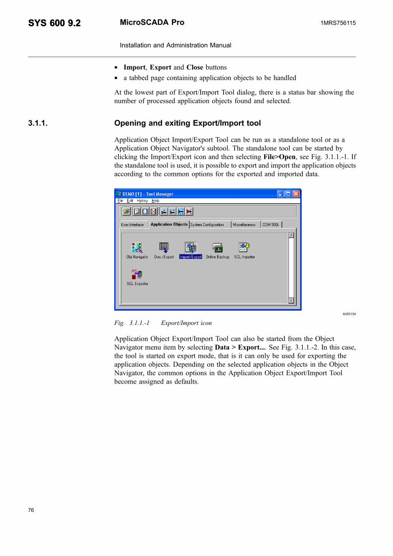
* Import, Export and Close buttons* a tabbed page containing application objects to be handled
At the lowest part of Export/Import Tool dialog, there is a status bar showing thenumber of processed application objects found and selected.
3.1.1. Opening and exiting Export/Import tool
Application Object Import/Export Tool can be run as a standalone tool or as aApplication Object Navigator's subtool. The standalone tool can be started byclicking the Import/Export icon and then selecting File>Open, see Fig. 3.1.1.-1. Ifthe standalone tool is used, it is possible to export and import the application objectsaccording to the common options for the exported and imported data.
A050154
Fig. 3.1.1.-1 Export/Import icon
Application Object Export/Import Tool can also be started from the ObjectNavigator menu item by selecting Data > Export.... See Fig. 3.1.1.-2. In this case,the tool is started on export mode, that is it can only be used for exporting theapplication objects. Depending on the selected application objects in the ObjectNavigator, the common options in the Application Object Export/Import Toolbecome assigned as defaults.
76
SYS 600 9.2SYS 600 9.2 MicroSCADA Pro
Installation and Administration Manual
1MRS756115

77
A051193
Fig. 3.1.1.-2 Open the tool from the Object Navigator dialog
When Application Object Export/Import Tool is started from the Object Navigatormenu item by selecting Data > Import. See 3.1.1.-2. In this case, the tool is startedon import mode, i.e. it can only be used for importing the application objects. Whenthe import operation is finished, the selected Object Navigator view becomesupdated.
Close the Export & Import Tool by clicking the Close button. The tool can also beclosed by selecting Object > Exit or by the keystroke Alt+F4. See Fig. 3.1.2.-1.
3.1.2. Exporting objects
Use common options to define the set of application objects to be exported. Theapplication objects that match the common options are listed in the ApplicationObjects tabbed page. Select the application objects that need to be exported. WhenSelect All is clicked, all the objects are selected. When Unselect All is clicked, noneof the objects are selected. To select separate application objects from the list, holdthe Ctrl key down while clicking the objects.
When the selection contains at least one application object, Export is enabled.When the button is clicked, a destination (export) file is created. See Fig. 3.1.2.-1.
When Export All is clicked, all objects are exported without selecting any objects.The Application Objects tabbed page shows only the first 10 000 objects in the list.The button also exports the objects that are not shown in the tabbed page.
MicroSCADA Pro
Installation and Administration Manual
SYS 600 9.2SYS 600 9.21MRS756115

A050155
Fig. 3.1.2.-1 Main dialog of Export/Import Tool
During the export operation, the progress indicator displays the operation progress.See Fig. 3.1.2.-2.
A050158
Fig. 3.1.2.-2 Export operation progress dialog
At the end of the export operation, either the objects were successfully exporteddialog is displayed or exceptions summary dialog is displayed. See Fig. 3.1.2.-3.
78
SYS 600 9.2SYS 600 9.2 MicroSCADA Pro
Installation and Administration Manual
1MRS756115

79
A050157
Fig. 3.1.2.-3 Objects are successfully exported
3.1.2.1. Exporting formats
The Export/Import tool supports three formats:
* ASCII File Format (ASC)* SCIL Database Format (SDB)* Comma Separated Values Format (CSV)
ASCII File Format (ASC)
The ASC Export format is an outdated export format. The ASC format is noteditable and data is saved in a slow sequential text file. The file name extension is .asc by default.
SCIL Database Format (SDB)
The SDB export format is based on the SCIL database files or SCIL data files. TheSDB format is not editable. The SCIL database files are not limited and the SCILdatabase's structure is optimized for fast access. Hence it is possible to transfer aprogram in one step with the SDB export format. The file name extension is .sdb bydefault.
Comma Separated Values Format (CSV)
The CSV export format is an editable export format and list-based engineering(LBE) uses it. The file name extension is .csv by default.
3.1.2.2. Defining CSV attributes
To form the CSV data, the following options are available:
* Delimiter is Comma
The data's delimiter is a comma (,) instead of a semicolon (;). Select theDelimiter is Comma check box, if the dot is used as a decimal point instead ofcomma.
* OI Attribute Split
MicroSCADA Pro
Installation and Administration Manual
SYS 600 9.2SYS 600 9.21MRS756115

The OI (Object Identifier) attribute of process objects can have a structure. If thestructure exists and the OI Attribute Split check box is selected, the attribute'svalue is splitted according to the attribute's structure.
* Attribute Name Header
By default the first row of the CSV data represents the two letter attribute names,which you can select. If the Attribute Name Header check box is selected, thefirst row represents mnemonic instead of attribute names and the two letterattribute names are represented on the second row.
* Vertical Text Vectors
By default the complicated attrubute values are represented as a dumped in a line(compare with SCIL function DUMP). If the Vertical Text Vectors check box isselected, the type text vector's attribute values are represented as vertical.
* Vertical Vectors
If Vertical Vectors check box is selected, the type none-text vector's attributevalues are represented as vertical.
* Vertical Lists
If Vertical Lists check box is selected, the type list vector's attribute values arerepresented as vertical.
Define how to form data, their attributes and their order in the CSV data, using theCSV Attibute Tool dialog as shown in Fig. 3.1.2.2.-1. To open the CSV AttributeTool dialog, select Tools > CSV Attributes from the Application Object Export\Import Tool dialog. See Fig. 3.1.2.2.-1.
A050160
Fig. 3.1.2.2.-1 Opening CSV Attribute Tool dialog
80
SYS 600 9.2SYS 600 9.2 MicroSCADA Pro
Installation and Administration Manual
1MRS756115

81
To define CSV attributes:
1. In the CSV Attribute Tool dialog, select the object type from the Object Typedrop-down list. If the pre-defined (IX) or user-defined (UP) process object typeis selected, select the sub type from the Sub Type drop-down list.
2. In the Sub Type drop-down list, either select the common attributes or theprocess object type specific attributes. See Fig. 3.1.2.2.-2
3. On clicking the CSV Attributes tab the following two lists are displayed: AllAttributes and Selected CSV Attributes. The All Attributes list contains allconfigurable attribute names, which are available for the current object type. TheSelected CSV Attributes list contains attribute names, which are selected fromthe All Attributes list. By selecting Edit menu, it is possible to edit the SelectedCSV Attributes list's attributes. See Fig. 3.1.2.2.-2.
4. There are three buttons between Selected CSVAttributes and All Attributes lists:left arrow, Reset and Save button. See Fig. 3.1.2.2.-2.* The left arrow button is enabled when one attribute is selected from the All
Attributes list. Click this button, if you want to copy the selected attributes tothe Selected Attributes list.
* Click the Reset button to select and move the configurable attributes to theSelected CSV Attributes list.
* Click the Save button to save all selected attribute names of the object typesto a file. When opening the CSVAttribute Tool again, the CSV attributes areread from this file. Attribute names are saved during the last export session bydefault, to the CSV_ATTRIBUTES.INI file. See Fig. 3.1.2.2.-2.
MicroSCADA Pro
Installation and Administration Manual
SYS 600 9.2SYS 600 9.21MRS756115

A050159
Fig. 3.1.2.2.-2 CSV Attribute Tool
5. Click the CSVAttribute File tab to change a CSV attribute file. Change the fileby clicking Set File (the button with three dots). New attribute names can beloaded from the file by clicking the Load File button. See Fig. 3.1.2.2.-3.
82
SYS 600 9.2SYS 600 9.2 MicroSCADA Pro
Installation and Administration Manual
1MRS756115

83
A050161
Fig. 3.1.2.2.-3 CSV Attribute File tab
3.1.2.3. Defining common options for exported data
In addition to the application and object type definitions, it is possible to defineother common options for the exported data. Define also the export type, availabletypes are ASC file format, CSV (Comma Separated Values) and SDB (SCILDatabase) formats.
Furthermore, it is possible to define SCIL Search Condition for the applicationobjects to be handled through this tool during the export. As a default, the SCILSearch Condition is empty. For example, if the Process Object's type is selected andthe SCIL Search Condition LN=="KUI_SABAY1" is defined, all the processobjects with Logical Name "KUI_SABAY1" become listed in the ApplicationObjects tabbed page. See Fig. 3.1.2.3.-1.
MicroSCADA Pro
Installation and Administration Manual
SYS 600 9.2SYS 600 9.21MRS756115

A051194
Fig. 3.1.2.3.-1 Filter dialog
The existing Filter Condition is applied by selecting the condition from the drop-down list or using the SCIL Search Condition dialog (the button with three dots).The tool stores the 30 latest Filter Conditions in the history list. The history list isread in the tool during its start-up.
The file name to be used as a destination (Export) is defined by selecting the filewith the File Chooser component (the button with three dots) on the right of thefield. The default file name is assigned to the running application's picture folder(logical path PICT is used). See Fig. 3.1.2.3.-2.
A050156
Fig. 3.1.2.3.-2 File chooser dialog
Regarding the file handling options, it is possible to define either Overwrite orAppend option. See Fig. 3.1.2.-1. In the Overwrite option, the existing destinationfile becomes always overwritten. Whereas in the Append option, the new data isappended into the end of the existing destination file. In the Append option, theexisting objects are only modified. If you choose SDB (SCIL Database) for export
84
SYS 600 9.2SYS 600 9.2 MicroSCADA Pro
Installation and Administration Manual
1MRS756115

85
type, the new data is not appended, if the data already exists. When Read File isclicked, the source file defined by file name is read and the result is shown in theApplication Objects tabbed page.
The Save Datalog Values option can be toggled on/off, depending whether the userwants to store the datalog values during the import operation. Default value is off.
3.1.3. Importing objects
The file name that contains the application objects is displayed in the commonoptions. When the application objects are read from the export file by clicking ReadFile button, the progress indicator displays the read or review operation progress.While previewing objects in the CSV format, the progress indicator cannot show thetotal number of objects. When all the application objects are read, they are listedinto the Application Objects tabbed page. Read objects are saved in a temporarySDB data file, except those objects, which are already in SDB format. Exceptionsthe preview are shown in the summary dialog. In addition, the Export/Import toolcreates the formats during the export. The Export/Import tool also recognizes LoadFile format (LOF files).
When Select All is clicked, all the objects is selected. When Unselect All is clicked,none of the objects is selected. To select separate application objects from the list,hold the Ctrl key down while clicking the objects.
When the selection contains at least one application object, the Import button isenabled, and when the button is clicked a source (import) file is read. SeeFig. 3.1.3.-1.
The Import All button also imports those objects that are not shown in the tabbedpage. The Application Objects tabbed page shows only the first 10 000 objects inthe list.
MicroSCADA Pro
Installation and Administration Manual
SYS 600 9.2SYS 600 9.21MRS756115

A050163
Fig. 3.1.3.-1 Main dialog of Export/Import Tool
During the import operation, the progress indicator displays the operation progress.See Fig. 3.1.3.-2. If the file cannot be read, an appropriate notification dialog isdisplayed for the user.
A051195
Fig. 3.1.3.-2 Import operation progress dialog
An exception can occur, when the tool imports application objects. Due to anexception, the application object cannot be created or modified according to theimport file. If one or multiple exceptions occur, they are listed in the ImportExceptions dialog. See Fig. 3.1.3.-3. This dialog displays the following information:
86
SYS 600 9.2SYS 600 9.2 MicroSCADA Pro
Installation and Administration Manual
1MRS756115

87
Type Letter that identifies the object type
Name Name of an object
Exception Context of exception (create new or modify an existing object)
Status SCIL status received from the system
Conflicting Object The name of the object that causes the conflict
A051196
Fig. 3.1.3.-3 Import Exceptions dialog
Functions of the dialog:
Button Functions
Save As... Opens the file chooser to specify the location for .log file to savethe occurred exceptions. As a default, the file chooser isopened in the application's PICT folder, and the default filename is Default.log.
Close Closes the dialog
3.1.3.1. Defining common options for imported data
In addition to the application and object type definitions, it is possible to defineother common options for the imported data.
The file name to be used as a destination source (Import) is defined by typing thefile name into appropriate field or selecting the file by using the File Choosercomponent (the button with three dots) on the right of the field. The default filename is assigned to the running application's picture folder (logical path PICT isused). See Fig. 3.1.2.3.-2.
Regarding the object handling options, it is possible to define either Overwrite orAppend option. In the Overwrite option, data of the existing destination object arealways overwritten. Whereas in the Append option, data of the object are appendedto a database, if the object does not exist.
The Create Dummy Scales and Create Dummy Event Handling Objects options canbe toggled on/off depending on whether the user wants to create scales and eventhandling objects that do not exist, while process objects are imported. Objects will
MicroSCADA Pro
Installation and Administration Manual
SYS 600 9.2SYS 600 9.21MRS756115

be created with their original names, but they are dummy. So, they should bemodified afterwards to make process objects work properly. The Import Exceptionsdialog informs about created objects.
The Save Datalog Values option can be toggled on/off, depending whether the userwants to store the datalog values during the import operation. Default value is off.
The Preimport Activities and Postimport Activities options can be toggled on/offdepending on whether the user wants to execute activities just before and after theproper import. Pre- and postimport definition tools are started from menu Tools —>Preimport ... and Tools —> Postimport ... . A pre/postimport command procedure/SCIL file is executed by DO function. In postimport an argument in DO functioncall is a list which includes all imported predefined process objects. The list is inform list(LN, IX), where the vector attribute LN includes logical names and IXindexes. The second argument passed in function call is the number of theapplication, where objects are imported into. Import tool assumes that procedures/SCIL files return the status of operation. If preimport fails, a notice dialog withstatus will be raised to ask whether to do the actual import or not. If preimport (orpostimport) totally fails (syntax error, etc.), the standard error dialog will be raisedand import will be interrupted.
3.2. Searching strings
The Search Tool is used for searching strings in objects and files. The tool cansearch strings through command procedure and data objects, text files, pictures andVisual SCIL Object files (VSO files). The Search Tool can be opened through theObject Navigator. The input for the tool is selected object types in the ObjectNavigator. If objects or files are also selected, they act as targets for the search. Thesearch type, target names and other search conditions are saved in the SEARCH.INIparameter file , when the tool is closed. The Search Tool can also act as a stand-alone tool and be opened through the Tool Manager.
3.2.1. Opening and exiting Search tool
Select Data > Search in Object Navigator to open the Search Tool. Before openingthe Search Tool, the object types can be selected in the Object Navigator. Theseobjects act as an input for the Search Tool. If no object type is selected, Text filesearch is default. If objects or files are also selected, they act as targets for thesearch. In Fig. 3.2.1.-1 the first four command procedures of the externalapplication are selected for search in the Object Navigator.
The Search Tool can also be opened as a stand-alone tool from the Tool Manager'sMiscellaneous tab.
88
SYS 600 9.2SYS 600 9.2 MicroSCADA Pro
Installation and Administration Manual
1MRS756115

89
A051529
Fig. 3.2.1.-1 Opening the Search Tool from Object Navigator.
Fig. 3.2.1.-2 shows Search Tool, when the tool is started through the ObjectNavigator. Note that in case the Search string(s) field is empty it should be filled outbefore the search can be completed.
A051530
Fig. 3.2.1.-2 View of the Search Tool started from Object Navigator.
Close the Search Tool by clicking Close. The tool can also be closed by selectingFile > Exit or by pressing ALT+F4.
MicroSCADA Pro
Installation and Administration Manual
SYS 600 9.2SYS 600 9.21MRS756115

3.2.2. Making searches
After defining the search conditions, click Search to start the search. Search canalso be started by pressing Enter.
When a search starts, the tool initializes a search first by locating targets accordingto search conditions. At this stage the empty Progress Indicator dialog is displayedand the Searching text is shown on the status bar. At initiation stage, it is notpossible to stop a search in the Search Tool. After the initiation, the proper searchtakes place, and the Stop button in the indicator dialog is enabled. A search isstopped by clicking Stop. The dialog disappears, the result page shows searchresults and the status bar informs about search statistics.
Fig. 3.2.2.-1 shows a picture search in progress.
A051531
Fig. 3.2.2.-1 A picture search in progress
Fig. 3.2.2.-2 shows a completed ‘VSO files’ search and one error is found.
90
SYS 600 9.2SYS 600 9.2 MicroSCADA Pro
Installation and Administration Manual
1MRS756115

91
A051532
Fig. 3.2.2.-2 A completed ‘VSO files’ search with a failure
3.2.3. Defining searches
The search conditions are the input for a search. They consist of a search type, anapplication, target names and paths, search strings, overlapping strings to beexcluded and two boolean options: Include subdirectories and match case.
Search conditions are saved in the SEARCH.INI parameter file when the SearchTool is closed.
If the search criteria (a search type, target names, target paths) include incompatiblefiles, a warning dialog informs that the incompatible files were skipped from thesearch. Dialog occurs if, for example, the following criteria are selected:
Search type Text files
Target name *
Target path Folder containing pictures and/or VSO files.
The files are skipped, because they are not text files.
Search types
Select the appropriate search type from the Search type drop-down list.
Supported search types for report database search:
* Command procedures* Data objects
Supported search types for file searches:
MicroSCADA Pro
Installation and Administration Manual
SYS 600 9.2SYS 600 9.21MRS756115
* Pictures* VSO files* Text files
When the Search Tool is opened, it displays the default search type, which dependson how the tool is started.
If Search Tool is started through Object Navigator, the default search type is selectedon Object Navigator. For example, if the VSO files object is selected on ObjectNavigator and Search Tool is opened. The default search type is VSO files in theSearch type drop-down list. If no object type is selected or Search Tool does notsupport the selected type, default search type is Text files.
If the tool is started as stand-alone, default search type is the last saved search typein the SEARCH.INI parameter file while the Search Tool was closed. If the tool isstarted for the first time, default search type is Command procedures.
When the appropriate type is selected, the Target names drop-down list is alsochanged to correspond the search type, see Fig. 3.2.2.-2.
Application
Select the application, where the search is performed, from the application drop-down list. The application list is updated when the search type is changed. Theoption is disabled when searching text files.
Applications are in the form <name>(n), where <name> is the application's nameand (n) is the application's logical number. Local applications are available for boththe file and database searches. External applications are available only for databasesearches.
If Search Tool is started through Object Navigator, the default application is theapplication that was selected before the Search Tool was opened. If the tool isstarted as stand-alone, default application is the last saved search type in theSEARCH.INI parameter file while the Search Tool was closed.
Target names
The Target names drop-down list can be edited. The Target names box can beedited as follows:
* Type a name or names separated with a delimiter. Wildcard characters areallowed in the names.
* Select an earlier saved item from the drop-down list.
92
SYS 600 9.2SYS 600 9.2 MicroSCADA Pro
Installation and Administration Manual
1MRS756115

93
* Select a file by browsing the directory. Add a file by clicking the Add file button.In the Select File dialog, select the appropriate file. The file name is the last inthe Target names box and it is separated by the delimiter from the other filenames. A directory name is added to the target paths box.
* Select objects or files in Object Navigator. The selected items are target nameswhen Search Tool is started. If the selected objects or files are more than 255characters long, the extra characters are removed. The search is single search,because of this the Target name box is disabled. To enable the Target namesdrop-down list, make another selection in Object Navigator or click the Add filebutton.
The default target names for the different search types:
Command procedures *
Picture *.PIC
VSO files *.VSO
Text files *
Data objects *
Target paths
The Target paths option can be used only for file searches. When performing thereport database searches, the option is disabled. The Target paths box can be editedas follows:
* Type a directory name or names separated with a delimiter.* Select an earlier saved item from the drop-down list.* Select a directory by browsing the directory. Add a directory by clicking the Add
file button. In the Select Directory dialog, select the appropriate directory. Thedirectory is the last in the Target paths box and it is separated by the delimiterfrom the other file names.
If the selected application is the current one (the application number is zero), thefield also accepts logical paths as input. For other local applications, logical pathsare not available. Therefore, when an application is selected in the Search Tool, thefield is changed to ‘PICT' and dimmed. The ‘PICT' stands for ‘\sc\apl\<apl_name>\pict'. It is not a logical path anymore.
Include subdirectories
If the Include subdirectories check box is selected, the tool also searches allsubdirectories. The option is used only for the file searches and it is disabled for theother searches.
MicroSCADA Pro
Installation and Administration Manual
SYS 600 9.2SYS 600 9.21MRS756115

Search strings
The Search strings drop-down list can be edited. Its text box shows a string orstrings to be searched. Different strings are separated by the delimiter to enablemultiple searches. Earlier searched strings can be selected to the text box from thesaved choices in the drop-down list.
Match case
If the Match case is selected, letters are case sensitive.
Exclude overlapping strings
Strings can be typed to the text box, when the Exclude overlapping strings checkbox selected.
When the check box is selected, a defined string is excluded from a search, if theyoverlap the strings selected in the Search strings box. When the check box is notselected, the text box is disabled.
Changing delimiter
The default delimiter is semicolon (;) and it separates the editable search conditionsitems. To open the Delimiter dialog, select Options > Set Delimiter.
When a delimiter is changed, all the choices containing old delimiter in the drop-down lists are updated with the new one.
3.2.4. Saving searches
Search results can be saved and printed. To save the search results, select File >Save Results and to print the search results, select File > Print Results.
Both produce the following output:
Search type: 'Pictures'
Target name(s): '*.PIC'
Target path(s): 'C:\SC\LIB4'
Search string(s): 'store'
Exclude overlapping string(s): '!restore'
Application: 0
Name Location Program Line Column Searchstring
C:\SC\LIB4\base\ALARM\USE
BAU_ALARM1.PIC
PF:ALARM_BASE EXIT 1 4 store
94
SYS 600 9.2SYS 600 9.2 MicroSCADA Pro
Installation and Administration Manual
1MRS756115
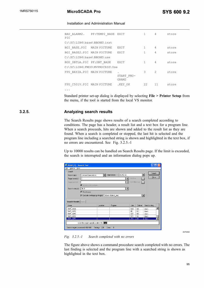
95
BAU_ALARM2.PIC
PF:TEMP2_BASE EXIT 1 4 store
C:\SC\LIB4\base\BBONE\inst
BGI_BASE.PIC MAIN PICTURE EXIT 1 4 store
BGI_BASE2.PIC MAIN PICTURE EXIT 1 4 store
C:\SC\LIB4\base\BBONE\use
BGU_DBTLA.PIC PF:DBT_BASE EXIT 1 4 store
C:\SC\LIB4\FMOD\MVPROCESS\Use
FPU_BAY2A.PIC MAIN PICTURE .START_PRO-GRAM2
3 2 store
FPU_C501V.PIC MAIN PICTURE .KEY_OK 22 11 store
...
Standard printer set-up dialog is displayed by selecting File > Printer Setup fromthe menu, if the tool is started from the local VS monitor.
3.2.5. Analyzing search results
The Search Results page shows results of a search completed according toconditions. The page has a header, a result list and a text box for a program line.When a search proceeds, hits are shown and added to the result list as they arefound. When a search is completed or stopped, the last hit is selected and theprogram line including a searched string is shown and highlighted in the text box, ifno errors are encountered. See Fig. 3.2.5.-1
Up to 10000 results can be handled on Search Results page. If the limit is exceeded,the search is interrupted and an information dialog pops up.
A070492
Fig. 3.2.5.-1 Search completed with no errors
The figure above shows a command procedure search completed with no errors. Thelast finding is selected and the program line with a searched string is shown ashighlighted in the text box.
MicroSCADA Pro
Installation and Administration Manual
SYS 600 9.2SYS 600 9.21MRS756115
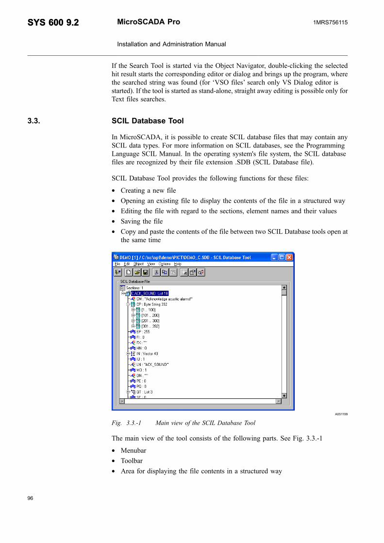
If the Search Tool is started via the Object Navigator, double-clicking the selectedhit result starts the corresponding editor or dialog and brings up the program, wherethe searched string was found (for ‘VSO files’ search only VS Dialog editor isstarted). If the tool is started as stand-alone, straight away editing is possible only forText files searches.
3.3. SCIL Database Tool
In MicroSCADA, it is possible to create SCIL database files that may contain anySCIL data types. For more information on SCIL databases, see the ProgrammingLanguage SCIL Manual. In the operating system's file system, the SCIL databasefiles are recognized by their file extension .SDB (SCIL Database file).
SCIL Database Tool provides the following functions for these files:
* Creating a new file* Opening an existing file to display the contents of the file in a structured way* Editing the file with regard to the sections, element names and their values* Saving the file* Copy and paste the contents of the file between two SCIL Database tools open at
the same time
A051199
Fig. 3.3.-1 Main view of the SCIL Database Tool
The main view of the tool consists of the following parts. See Fig. 3.3.-1
* Menubar* Toolbar* Area for displaying the file contents in a structured way
96
SYS 600 9.2SYS 600 9.2 MicroSCADA Pro
Installation and Administration Manual
1MRS756115

97
3.3.1. Opening the SCIL Database File
When File > Open is selected or the appropriate toolbar button is clicked, the FileChooser dialog is opened. See Fig. 3.3.1.-1.
A051205
Fig. 3.3.1.-1 Selecting a file in File Chooser
The default folder for File Chooser is the active application's PICT folder. The files,which have the .SDB extension are shown as default. When the SCIL Database fileto be opened is located in another folder, use the File Chooser to select theappropriate drive and folder. To open the file, select the file name from the list ortype the name of the file to the File name field. It is also possible to open the latestfiles from the tool's file history list, located in the File menu of the tool.
When the file is opened, its contents is displayed in the tool in a structured way.
If the Text Database files (SYS_TEXT.SDB, APL_TEXT.SDB or otherText Database files defined by the APL:BTD Text Databases attribute)are opened in SCIL Database Tool, the following dialog is displayedfor the user. See Fig. 3.3.1.-2.
A051206
Fig. 3.3.1.-2 Notification for opened Text Database files
MicroSCADA Pro
Installation and Administration Manual
SYS 600 9.2SYS 600 9.21MRS756115
In this case, the tool disables the saving function. This is because, the TextTranslation Tool should be used for localization purposes of these files. However, itis possible to edit the contents of this file, and save it to another file name.
When the file is opened in the tool, its contents is shown in the tree. Sections nodeof the tree displays the number of sections included in this file. As a default, theSections node is expanded, thus displaying all the sections found from the file. Thecontents of each section becomes displayed, when the appropriate Section node inthe tree is expanded.
For each section and element, the following information is displayed:
* Name of the section or element* Data type of the section or element* Value of the section or element
Section is identified in the tree with following icon.
The data types for element values are identified with icons according to thefollowing Fig. 3.3.1.-3
98
SYS 600 9.2SYS 600 9.2 MicroSCADA Pro
Installation and Administration Manual
1MRS756115
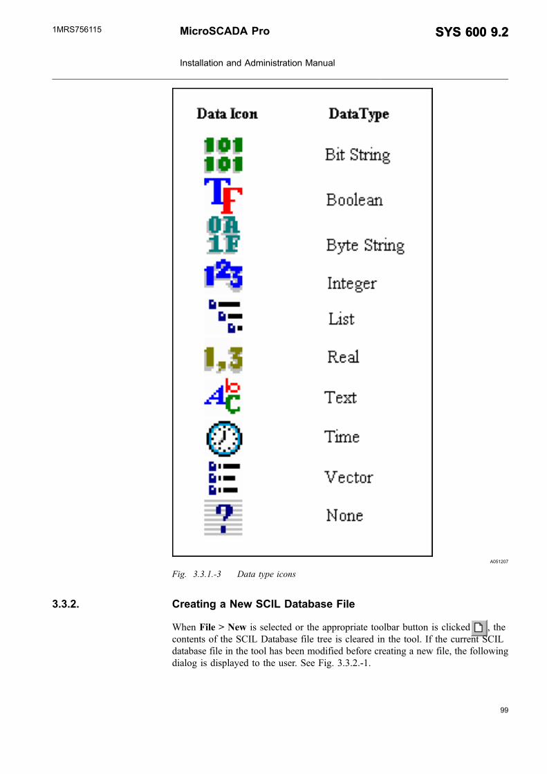
99
A051207
Fig. 3.3.1.-3 Data type icons
3.3.2. Creating a New SCIL Database File
When File > New is selected or the appropriate toolbar button is clicked , thecontents of the SCIL Database file tree is cleared in the tool. If the current SCILdatabase file in the tool has been modified before creating a new file, the followingdialog is displayed to the user. See Fig. 3.3.2.-1.
MicroSCADA Pro
Installation and Administration Manual
SYS 600 9.2SYS 600 9.21MRS756115

A051200
Fig. 3.3.2.-1 Current file is modified notification
When Yes is clicked, the tool saves the current SCIL database file before clearingthe contents of tree. If No is clicked, the contents of tree is cleared without savingthe content of the current SCIL database file. If Cancel is clicked, the contents oftree is not cleared.
3.3.3. Creating New Section with Value
When root node Sections is selected in the tree, select Object > New from themenubar or click the appropriate toolbar button . Then the New dialog isopened. See Fig. 3.3.3.-1
A051201
Fig. 3.3.3.-1 Opening the New dialog
Type the section name in the Section text field, and the value in the Value text field.Here are some examples for entered values:
TRUE
10
"10"
LIST(FIRST=1, SECOND=VECTOR(1,2,3), THIRD=TIME)
VECTOR(TRUE, FALSE, 12)
Clicking OK or pressing ENTER creates a new section in the tool with the enteredvalue and closes the New dialog. Clicking Cancel discards the entered section withvalue and closes the dialog.
100
SYS 600 9.2SYS 600 9.2 MicroSCADA Pro
Installation and Administration Manual
1MRS756115
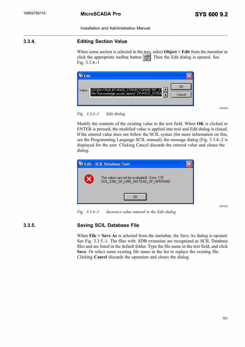
101
3.3.4. Editing Section Value
When some section is selected in the tree, select Object > Edit from the menubar orclick the appropriate toolbar button . Then the Edit dialog is opened. SeeFig. 3.3.4.-1
A051202
Fig. 3.3.4.-1 Edit dialog
Modify the contents of the existing value in the text field. When OK is clicked orENTER is pressed, the modified value is applied into tool and Edit dialog is closed.If the entered value does not follow the SCIL syntax (for more information on this,see the Programming Language SCIL manual), the message dialog (Fig. 3.3.4.-2 isdisplayed for the user. Clicking Cancel discards the entered value and closes thedialog.
A051203
Fig. 3.3.4.-2 Incorrect value entered in the Edit dialog
3.3.5. Saving SCIL Database File
When File > Save As is selected from the menubar, the Save As dialog is opened.See Fig. 3.3.5.-1. The files with .SDB extension are recognized as SCIL Databasefiles and are listed in the default folder. Type the file name in the text field, and clickSave. Or select some existing file name in the list to replace the existing file.Clicking Cancel discards the operation and closes the dialog.
MicroSCADA Pro
Installation and Administration Manual
SYS 600 9.2SYS 600 9.21MRS756115

A051208
Fig. 3.3.5.-1 Save as dialog
If an existing file has been modified in the tool, select File > Save from the menubaror click the appropriate toolbar button to save the file with the same name.
3.3.6. Renaming Sections
Select some existing section in the tree, and select Object > Rename from the menuor click the appropriate toolbar button . Then the Rename dialog is opened. SeeFig. 3.3.6.-1
A051204
Fig. 3.3.6.-1 Rename dialog
Type another section name in the text field. Clicking OK or pressing ENTERaccepts the entered section name in the tool and closes the Rename dialog. ClickingCancel discards the entered new section name and closes the dialog.
3.3.7. Deleting Selected Content
Select some existing section or value in the tree, and select Edit > Cut or click theappropriate toolbar button. The selected content is deleted. However, it is possible topaste this section or value later, because it is saved to the clipboard of tool.
102
SYS 600 9.2SYS 600 9.2 MicroSCADA Pro
Installation and Administration Manual
1MRS756115

103
3.3.8. Transferring information between two SCIL Database Tools
It is possible to copy and paste section and value information between two parallelSCIL Database Tools. The purpose of this function is to provide easier engineering,when there is a need to reuse the data from one SCIL Database File to another. Thiscan be done by the following way:
1. Start the first SCIL Database Tool from the Tool Manager.
2. Start the second SCIL Database Tool from Tool Manager
3. Open the SCIL Database in this tool. Select some section name in the tree.
4. Select Edit > Copy from the menubar or click the appropriate toolbar button.
The contents of the selected section is copied to the clipboard of the first tool.After this is done, do as follows:
5. Select the root node of the tree, that is, click the Sections item.
6. Select Edit > Paste from the menubar or click the appropriate toolbar button.
The contents of the copied section is pasted in the contents of the second tool. SeeFig. 3.3.8.-1
A051209
Fig. 3.3.8.-1 Transferring information between two tools
3.4. Hard disk management
The Disk Management Tool (DMT) is designed for automatic and manual hard diskmanagement in MicroSCADA Pro, that is file deleting, moving and compression, inorder to free up disk space. The Disk Management Tool requires MicroSCADAversion 8.4.3 or higher. The DMT uses external executable AR.EXE forcompression.
The Disk Management Tool is able to perform the following actions to maintain thedisk space available:
* Deleting files* Moving files to another hard disk or removable media* Compressing files and deleting original ones, archives created by the DMT are
handled by the DMT User Interface part
The DMT can be activated in one or more of the following ways:
* Manual triggering via the User Interface* Automatic periodic triggering at predefined time of the day* Automatic triggering based on the LIB 5xx hard disk space alarm
MicroSCADA Pro
Installation and Administration Manual
SYS 600 9.2SYS 600 9.21MRS756115
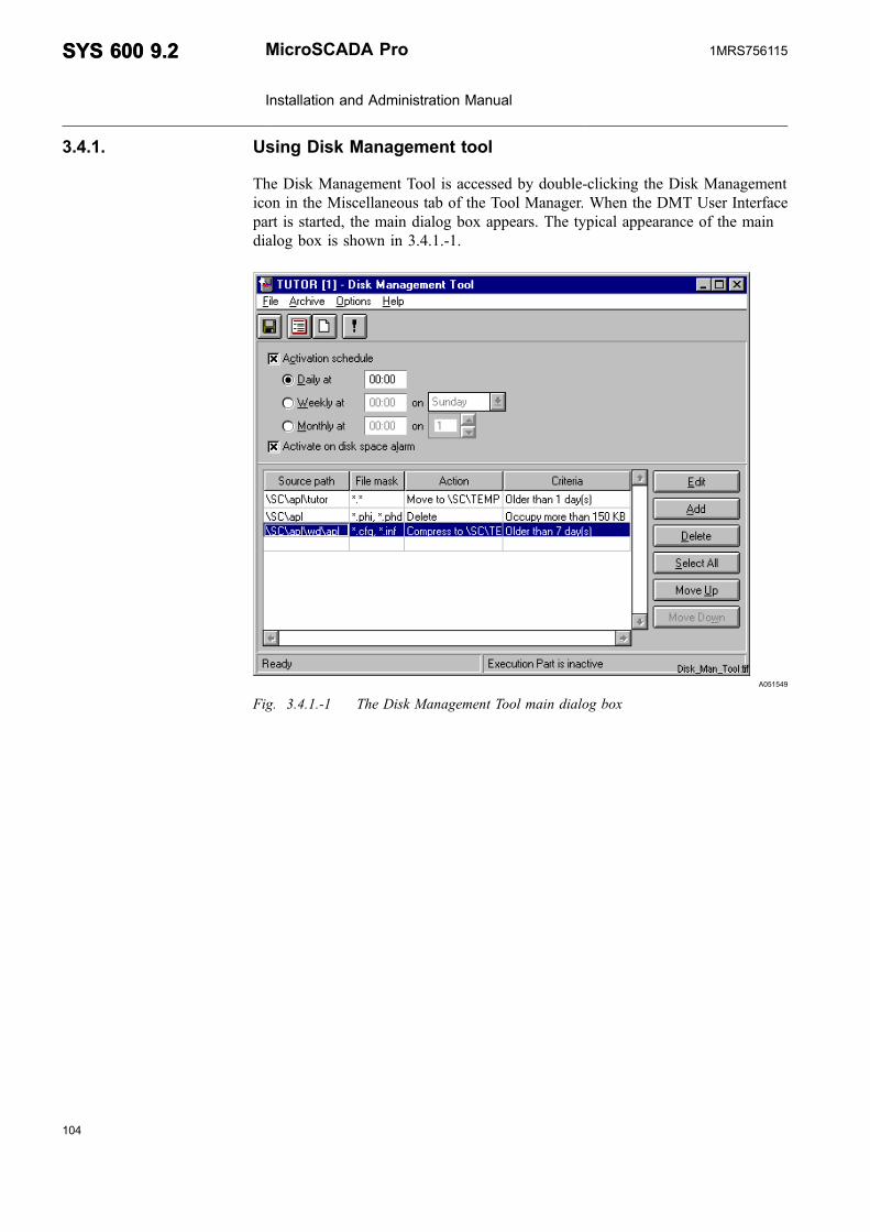
3.4.1. Using Disk Management tool
The Disk Management Tool is accessed by double-clicking the Disk Managementicon in the Miscellaneous tab of the Tool Manager. When the DMT User Interfacepart is started, the main dialog box appears. The typical appearance of the maindialog box is shown in 3.4.1.-1.
A051549
Fig. 3.4.1.-1 The Disk Management Tool main dialog box
104
SYS 600 9.2SYS 600 9.2 MicroSCADA Pro
Installation and Administration Manual
1MRS756115
105
Menus
Table 3.4.1.-1 File menu commands
Save This command saves current activation settings and file sets tothe parameter file. Base system objects are updated accordingto the new activation settings. The left toolbar button alsocorresponds to this command.
View Log View logThis command opens the viewer dialog box to view thelog created by the Execution part. Log messages are displayedas plain text, each one on a single line. Messages include dateand time stamp, message type (information, caution and critical),and the message text.‘Information' messages are those not requiring immediateattention, such as the number of processed files from each fileset, the time when the Execution part was started and so on.‘caution' messages are logged when there is an I/O or other no-critical error, but the DMT is able to recover and continueexecution.‘critical' messages are logged when there is a critical error, whichhas caused the Execution part to stop.Note that the log viewer is able to display up to10000 messagesof the log, so it is necessary to clear the log periodically. The logfile is stored in the language-independent format. When it isviewed in the UI part, messages are translated using the currentlanguage. The second toolbar button corresponds to thiscommand.
Clear log This command empties the log file and immediately logs amessage that the log file was cleared. The third toolbar buttonalso corresponds to this command.
Run now This command activates the Execution part immediately, if it isnot already running. If there are unsaved changes in file sets oractivation settings, the tool prompts whether to save them priorto activating the Execution part. The fourth toolbar button alsocorresponds to this command.
View messages This command shows the dialog box containing recentmessages received from the Execution part. The dialog box alsoopens automatically when a new ‘critical' or ‘caution' message isreceived. See for more detailed description of the messagedialog.
Exit This command closes the UI dialog box. If there are unsavedchanges in file sets or activation settings, the tool promptswhether to save them.
Table 3.4.1.-2 Archive menu command
Open This command allows the user to view and extract files fromarchives created by the Execution part. See for the description ofthe archive-handling dialog.
MicroSCADA Pro
Installation and Administration Manual
SYS 600 9.2SYS 600 9.21MRS756115

Table 3.4.1.-3 Options menu command
Toolbar Visible This option toggles the toolbar state.
Table 3.4.1.-4 Help menu command
About This command opens the About information sheet.
Toolbar
Corresponds to the Save command in the File menu.
Corresponds to the View log command in the File menu.
Corresponds to the Clear log command in the File menu.
Corresponds to the Run now command in the File menu.
3.4.1.1. Activating automatic disk space settings
The following activation methods are supported by the Disk Management Tool(DMT):
* The time-based activation (daily, weekly or monthly)* The activation based on LIB 500 disk space alarm
These options are independent of each other, but only one instance of the Executionpart may run at a time. Therefore, if the Execution part was triggered by the diskspace alarm or manually, and has not finished before the time-based activation hasoccurred, then the time-based activation is ignored.
1. Setting a daily, weekly or monthly activation in the main dialog
2. Select the Activation schedule check box in order to activate the option buttons.See
3. Select on of the following options, Daily at, Weekly at or Monthly at, dependingon which kind of activation is preferred.
Type the time of the day for the activation in the freely editable text box next to theoption button. The time must be typed in 24 hour format, for example 16:30. For theDaily at activation, in addition to the time of the day, also the day of the week has tobe selected from the drop-down list next to the time text box. For the Monthly atactivation, in addition to the time of the day, also the date has to be selected from thespin box next to the time text box.
The monthly activation will be ignored on months, which do not contain theselected day. For example, the Execution part will not be activated on February, ifthe 30th day is selected.
Setting activation on disk space alarm is done by selecting the Activate on diskspace alarm check box. The disk space alarm limit can be adjusted with the LIattribute of the process object 10 in the B_HDS process object group, see theApplication Objects manual for more detailed information on adjusting the attribute.
106
SYS 600 9.2SYS 600 9.2 MicroSCADA Pro
Installation and Administration Manual
1MRS756115

107
Changing B_HDS process object group also effects LIB 5xx since it uses the samegroup. If LIB 5xx is installed after adjusting the LI attribute, the LIB 5xx defaultvalue will replace the adjusted value.
3.4.1.2. Creating new file sets
Each file set consists of the following attributes:
Table 3.4.1.2.-1 File attributes
Source path This is the directory specification, where source files are located. It can beapplication-related or operating system-dependent absolute path.
File mask This attribute is the pattern of the file names to operate on. It is alsopossible to specify several patterns separated by semicolon. The DMTcorrectly handles file names matching more than one pattern. Forexample, if A*.* and *.PHD are specified, APL_991004.PHD will beprocessed only once.
Action One of the following actions can be performed by DMT on file sets:Delete: Deletes all files matching the pattern and criteria.Move: Moves all files matching the pattern and criteria to another location.Compress: Places all files matching the pattern and criteria into the archiveand deletes original ones if the operation was successful. The archive filename can be a maximum of eight characters long, excluding the extension.The extension can be freely chosen and a maximum of three characterslong. Character selection for both the archive name and the extensionfollow the standard DOS file naming convention. Note that for thecompression operation to succeed, the amount of free disk space on thedrive where MicroSCADA is installed needs to be more than twice the sizeof the files to be compressed.
ActionDestination
This attribute is only applied for Move and Compress actions. For Moveaction, it specifies the directory, where to move the affected files. For theCompress action, it specifies the destination archive file. The archive namecan be a maximum of eight characters long, excluding the three characterextension, because the destination file name is given as an argument toAR.EXE.
Criteria One of the following criteria can be checked by the DMT to find outwhether to process the file set:Time: All files older than the specified time stamp and matching the patternare processed.Size: If the size of any file matching the pattern is greater than the specifiedlimit, the file is processed.
Criteria value This is the number of criteria units, selected for the file set. This value mustbe between 1 and 999.
Criteria unit The following units are applied to the ‘Time' criteria:‘day'‘month'‘year'
The following units are applied to the ‘Size' criteria:
KB Kilobyte, is equivalent to 1 000 bytes.
MB Megabyte, is equivalent to 1 000 000 bytes
GB Gigabyte, is equivalent to 1 000 000 000 bytes
MicroSCADA Pro
Installation and Administration Manual
SYS 600 9.2SYS 600 9.21MRS756115
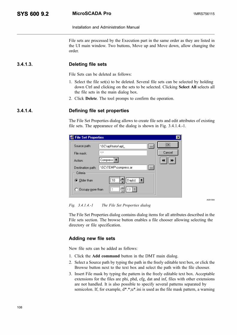
File sets are processed by the Execution part in the same order as they are listed inthe UI main window. Two buttons, Move up and Move down, allow changing theorder.
3.4.1.3. Deleting file sets
File Sets can be deleted as follows:
1. Select the file set(s) to be deleted. Several file sets can be selected by holdingdown Ctrl and clicking on the sets to be selected. Clicking Select All selects allthe file sets in the main dialog box.
2. Click Delete. The tool promps to confirm the operation.
3.4.1.4. Defining file set properties
The File Set Properties dialog allows to create file sets and edit attributes of existingfile sets. The appearance of the dialog is shown in Fig. 3.4.1.4.-1.
A051594
Fig. 3.4.1.4.-1 The File Set Properties dialog
The File Set Properties dialog contains dialog items for all attributes described in theFile sets section. The browse button enables a file chooser allowing selecting thedirectory or file specification.
Adding new file sets
New file sets can be added as follows:
1. Click the Add command button in the DMT main dialog.
2. Select a Source path by typing the path in the freely editable text box, or click theBrowse button next to the text box and select the path with the file chooser.
3. Insert File mask by typing the pattern in the freely editable text box. Acceptableextensions for the files are phi, phd, cfg, dat and inf, files with other extensionsare not handled. It is also possible to specify several patterns separated bysemicolon. If, for example, d*.*;u*.ini is used as the file mask pattern, a warning
108
SYS 600 9.2SYS 600 9.2 MicroSCADA Pro
Installation and Administration Manual
1MRS756115

109
shown in Figure 11.2.2.-2 is displayed. The warning appears after the first file setthat may include not supported files, has been approved, but only once everytime the DMT is used.
A051595
Fig. 3.4.1.4.-2 Warning about a file mask that may include files not supported by theDMT.
4. Select the appropriate Action for processing the files included in the file mask.The drop-down list provides the Delete, Compress and Move options.
5. The destination path has to be defined for the Move and Compress actions. Typethe path in the freely editable text box or click on the browse button to select thepath by file chooser. For Compress action a file name for the archive file needs tobe defined in addition to the destination path, for example \sc\temp\compress.ar.
6. In the Criteria group box, click Older than to select time criteria or Occupy morethan to select space criteria.
7. Select the criteria value from it’s respective spin box and unit from it’s respectivedrop-down list.
8. Click OK to accept the settings.
The OK button propagates the new file set to the main dialog and then closes theFile Set Properties dialog.
The Cancel button abandons any changes and closes the dialog. If there are unsavedmodifications, the tool prompts whether to save them.
Editing existing file sets
Existing file sets can be edited as follows:
1. In the DMT main dialog click on the file set to be edited.
2. Click the Edit button.
3. Do the necessary changes in the File Set Properties dialog.
4. Click OK.
5. The OK button propagates changes to the main dialog and then closes the FileSet Properties dialog.
The Cancel button abandons any changes and closes the dialog. If there are unsavedmodifications, the tool prompts whether to save them.
MicroSCADA Pro
Installation and Administration Manual
SYS 600 9.2SYS 600 9.21MRS756115
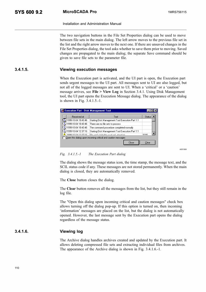
The two navigation buttons in the File Set Properties dialog can be used to movebetween file sets in the main dialog. The left arrow moves to the previous file set inthe list and the right arrow moves to the next one. If there are unsaved changes in theFile Set Properties dialog, the tool asks whether to save them prior to moving. Savedchanges are propagated to the main dialog; the separate Save command should begiven to save file sets to the parameter file.
3.4.1.5. Viewing execution messages
When the Execution part is activated, and the UI part is open, the Execution partsends urgent messages to the UI part. All messages sent to UI are also logged, butnot all of the logged messages are sent to UI. When a ‘critical’ or a ‘caution’message arrives, see File > View Log in Section 3.4.1. Using Disk Managementtool, the UI part opens the Execution Message dialog. The appearance of the dialogis shown in Fig. 3.4.1.5.-1.
A051569
Fig. 3.4.1.5.-1 The Execution Part dialog
The dialog shows the message status icon, the time stamp, the message text, and theSCIL status code if any. These messages are not stored permanently. When the maindialog is closed, they are automatically removed.
The Close button closes the dialog.
The Clear button removes all the messages from the list, but they still remain in thelog file.
The "Open this dialog upon incoming critical and caution messages" check boxallows turning off the dialog pop-up. If this option is turned on, then incoming‘information’ messages are placed on the list, but the dialog is not automaticallyopened. However, the last message sent by the Execution part opens the dialogregardless of the message status.
3.4.1.6. Viewing log
The Archive dialog handles archives created and updated by the Execution part. Itallows deleting compressed file sets and extracting individual files from archives.The appearance of the Archive dialog is shown in Fig. 3.4.1.6.-1.
110
SYS 600 9.2SYS 600 9.2 MicroSCADA Pro
Installation and Administration Manual
1MRS756115

111
A051597
Fig. 3.4.1.6.-1 The Execution Part dialog
The Source file text box shows the name and the path of the currently open archive.The corresponding Browse button allows selecting another archive.
The leftmost list contains IDs of compressed file sets in the first column. IDs are 4-digit numbers assigned in the ascending order. The result of the first compressionreceives the ID 0000, the next one has the ID 0001, and so on. Other two listcolumns contain the original and the compressed size of the whole data.
The rightmost group box displays the following information related to the selectedfile set:
* Time stamp, the date/time when the compression was performed* Location, the original location of files* File mask, the file mask of the file set* Condition, the condition used to select files* The list, that shows the name and the original size for each file
The Refresh command button forces the tool to refresh the contents of the archive. Itis useful to reflect changes made by the recent activation of the Execution part.
The Extract files... command button allows to extract all or only selected files fromone file set at a time. When this button is clicked, a dialog is displayed allowingchanging the destination directory.
The Delete file set button allows deleting one or more selected file sets. There is noway to delete individual files from a compressed file set.
MicroSCADA Pro
Installation and Administration Manual
SYS 600 9.2SYS 600 9.21MRS756115

3.5. Starting SYS 600
3.5.1. Starting base systems
To start a base system:
1. Switch on the computer and the display.
2. After the power has been switched on, the memory is tested and the operatingsystem is started.
3. MicroSCADA can be started either manually or automatically, depending on theconfigurations made to the system.
4. You can log on to Windows, either automatically or manually, depending on theconfigurations you have made to the system. Manual logging is needed only ifmonitors are opened manually in the same computer where base system isrunning.
3.5.2. Base System startup procedures
Base system runs as a service in the operating system. This means that the programruns in the background without any visible user interface.
At startup, the MicroSCADA main program runs the following operations:
* The base system is configured with the SYS_BASCON.COM file.* The remote communication system is configured and possible NET units are
started (SYS_NETCON.COM).
3.5.3. Application startup procedures
The applications that are configured in the SYS_BASCON.COM are started afterthe service has started. For each application that has started and has been set to"HOT", the following tasks are performed:
* The entire process database of the application is copied from disk to the primarymemory. The values for process objects with SS= =2 are marked as not logged(status code 10).
* An event channel (APL_INIT_1) is activated. Often the channel starts anapplication-specific command procedure(s). The function is defined in the eventchannel configurations.
* All time channels in the active applications, which are connected to data objectsand should have started during the system break, are executed. The missingreport data, due to the break, is marked as not logged. Command procedures anddata objects with SE= =1 are executed. After the marking of data objects iscomplete, another event channel (APL_INIT_2) starts another commandprocedure(s).
The tasks are performed regardless of whether they are started from theSYS_BASCON.COM file or later on. If the application is a part of a hot stand-bysystem, the procedures are identical.
112
SYS 600 9.2SYS 600 9.2 MicroSCADA Pro
Installation and Administration Manual
1MRS756115

113
The command procedure started by APL_INIT_1 is normally programmed toperform, for example, the following operations:
* Reading process object values from the remote terminal units and updating themin the process database (the primary memory).
* Completing and modifying the equipment/line configuration. The commandprocedure started by APL_INIT_2 can, for example, be programmed to sendmessages to printers.
3.5.4. Manual startup of SYS 600 Monitor
Manual startup means that MicroSCADA is started manually, from theMicroSCADA Control Panel. If the base system has not been configured forautomatic startup, start the MicroSCADA manually.
To start:
1. Log into the operating system as a user belonging to the Administrator group.
2. Double-click the MicroSCADA Control Panel icon.
3. The MicroSCADA Control Panel is displayed as shown in Fig. 2.1.5.-2.
A051222
Fig. 3.5.4.-1 MicroSCADA Control Panel
4. Click Start.
5. The dialog box is displayed as shown in Fig. 3.5.4.-2.
A051223
Fig. 3.5.4.-2 This dialog box tells that MicroSCADA has been started
MicroSCADA Pro
Installation and Administration Manual
SYS 600 9.2SYS 600 9.21MRS756115
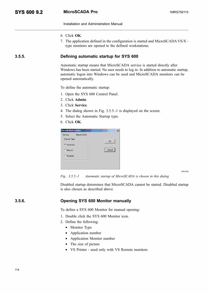
6. Click OK.
7. The application defined in the configuration is started and MicroSCADAVS/X -type monitors are opened to the defined workstations.
3.5.5. Defining automatic startup for SYS 600
Automatic startup means that MicroSCADA service is started directly afterWindows has been started. No user needs to log in. In addition to automatic startup,automatic logon into Windows can be used and MicroSCADA monitors can beopened automatically.
To define the automatic startup:
1. Open the SYS 600 Control Panel.
2. Click Admin.
3. Click Service.
4. The dialog shown in Fig. 3.5.5.-1 is displayed on the screen.
5. Select the Automatic Startup type.
6. Click OK.
A051229
Fig. 3.5.5.-1 Automatic startup of MicroSCADA is chosen in this dialog
Disabled startup determines that MicroSCADA cannot be started. Disabled startupis also chosen as described above.
3.5.6. Opening SYS 600 Monitor manually
To define a SYS 600 Monitor for manual opening:
1. Double click the SYS 600 Monitor icon.
2. Define the following:* Monitor Type* Application number* Application Monitor number* The size of picture* VS Printer - used only with VS Remote monitors
114
SYS 600 9.2SYS 600 9.2 MicroSCADA Pro
Installation and Administration Manual
1MRS756115

115
A051226
Fig. 3.5.6.-1 Basic MicroSCADA Monitor (SYS 600 Monitor) Definitions
3. Click OK.
The options available to define the monitor include:
Monitor Type: Choose the monitor type you want to open from the following:
* VS Local
This is the local Visual SCIL monitor and requires no X emulation software. TheMicroSCADA base system must be on the computer from where theMicroSCADA monitor is started.
* VS Remote
This is the remote Visual SCIL monitor. It requires an X-server on the computerwhere the MicroSCADA monitor is to be displayed. The MicroSCADA basesystem can be on any computer on the network and the MicroSCADA monitorcan be opened to any computer on the network, provided that the privileges aresufficient and network configuration allows it.
* X
This is the X monitor. It requires an X-server on the computer where theMicroSCADA monitor is to be displayed. The MicroSCADA base system can beon any computer on the network and the MicroSCADA monitor can be openedon any computer on the network, provided that the privileges are sufficient andnetwork configuration allows it.
Application #: Choose the application you want to connect to.
Application Monitor #: Choose the MicroSCADA monitor in the application youwant to use.
Picture Size: Choose the picture size to be used in the MicroSCADA monitor.
MicroSCADA Pro
Installation and Administration Manual
SYS 600 9.2SYS 600 9.21MRS756115

The possibilities are:
* 640 by 480 pixels* 960 by 720 pixels* 1280 by 960* 1600 by 1200 pixels
Picture size is always 48x80. Semi graphic characters and the sizes of the fonts are:
* 8x10* 12x15* 16x20* 20x25
VS Printer: This property is only used with VS Remote monitors. This printer isused for Visual SCIL screen dumps and the output for the Visual SCIL objectVS_PRINT_OBJECT.
Example:
For example the printer LPT1 stands for the local printer using the LPT1:parallel port connected to the MicroSCADA base system computer. You canalso give an UNC path to a printer shared on the network. The UNC path tothe printer shared as MYPRINTER on the computer MYCOMPUTER is: \\MYCOMPUTER\MYPRINTER.
The MicroSCADA user must have appropriate rights to use the shared printer. Theprinter defined must be a postscript printer
Opening a Predefined MicroSCADA monitor
To open a predefined MicroSCADA monitor:
1. Select In Use check box.
2. Insert the setting number and the name of the base system computer where themonitors.dat file is. These definitions are described in Section 3.5.8.Automatically opened MicroSCADA monitors
3. Click OK.
3.5.7. Automatic logon of SYS 600
Automatic startup means that MicroSCADA service is started directly after theWindows has been started. No user needs to log in. In addition to automatic startup,automatic logon into Windows can be used and MicroSCADA monitors can beopened automatically.
To enable automatic logon:
116
SYS 600 9.2SYS 600 9.2 MicroSCADA Pro
Installation and Administration Manual
1MRS756115

117
1. Open the SYS 600 Control Panel.
2. Click Admin.
3. Click AutoLogon.
4. The dialog shown in the Fig. 3.5.7.-1, is displayed on the screen.
A051230
Fig. 3.5.7.-1 Automatic logon of SYS 600 Monitor
5. Type the user name and the password.
6. Select Automatic Logon Enabled.
7. Click OK.
Using Automatic Logon might compromise the security of the MicroSCADAsystem. To override Automatic Logon, press the SHIFT key during Windowsstartup. The user is prompted for the user name and password. If the user logs on asa different user than was defined for the Automatic Logon, the Automatic Logonhas to be re-enabled from the SYS 600 Control Panel.
3.5.8. Automatically opened MicroSCADA monitors
When MicroSCADA is started, the monitors can be opened automatically, forexample, to the operator workstations.
Predefined MicroSCADA monitors
Predefined monitors (up to 999) can be defined to simplify and automate the startupof MicroSCADA monitors. The MicroSCADA monitors are defined in the filemonitors.dat located in the \sc\sys\active\sys_ folder of the base system computer.
To define predefined monitors:
1. Edit the monitors.dat file in a text editor. The monitors.dat file is described in thefollowing section.
2. Copy a monitor definition block of the required type and change the predefinedmonitor number to a previously unused number.
3. Modify the block to meet your needs regarding:* MicroSCADAmonitor type* application* logical monitor number
MicroSCADA Pro
Installation and Administration Manual
SYS 600 9.2SYS 600 9.21MRS756115

* semi-graphic font* display* print file
To change the font, copy the desired font name of the MicroSCADA monitortype in question from the comment part of the file. When entering a print filename in the file, the name must end with a colon (:).
4. Save the file as an ASCII file.
Monitors.dat
The monitors.dat file is a text file with a specified format. The default monitors.datfile has the following contents:
; The comments (lines beginning with ’;’) can be removed.; NOTE no space character is allowed before and after the equal sign; The following attributes can be set for the different monitors;; VS Local Monitor:; SCS_MON_TYPE; LVS; SCS_MS_WINDOWS_APPLICATION; 0 - 20 (0 stands for default); SCS_MS_WINDOWS_MONITOR; 0 - 50 (0 stands for default); SCS_X_TERMINAL_FONT; family:MicroSCADA0810-size:10; family:MicroSCADA1215-size:15; family:MicroSCADA1620-size:20; family:MicroSCADA2025-size:25; FONT; family:MS Sans Serif-size:8 (default); DISPLAY; (should be empty); VS Remote Monitor:; SCS_MON_TYPE; RVS; SCS_MS_WINDOWS_APPLICATION; 0 - 20 (0 stands for default); SCS_MS_WINDOWS_MONITOR; 0 - 50 (0 stands for default); SCS_X_TERMINAL_FONT; -abb-scada-medium-r-normal–10-100-75-75-c-100-iso8859-1; -abb-scada-medium-r-normal–15-150-75-75-c-100-iso8859-1; -abb-scada-medium-r-normal–20-200-75-75-c-100-iso8859-1; -abb-scada-medium-r-normal–25-250-75-75-c-100-iso8859-1; FONT; family:helvetica-size:12 (default); DISPLAY; the name of the display; PRINTFILE; the name of the printer to send monitor dumps; note: the printer "name" must end with a colon;;; X Monitor:; SCS_MON_TYPE; XMON; SCS_X_TERMINAL_APPLICATION; 0 - 20 (0 stands for default); SCS_X_TERMINAL_MONITOR; 0 - 50 (0 stands for default); SCS_X_TERMINAL_FONT; -abb-scada-medium-r-normal–10-100-75-75-c-100-iso8859-1; -abb-scada-medium-r-normal–15-150-75-75-c-100-iso8859-1; -abb-scada-medium-r-normal–20-200-75-75-c-100-iso8859-1; -abb-scada-medium-r-normal–25-250-75-75-c-100-iso8859-1; DISPLAY; the name of the display[1]SCS_MON_TYPE=LVSSCS_MS_WINDOWS_APPLICATION=0SCS_MS_WINDOWS_MONITOR=0SCS_X_TERMINAL_FONT=family:MicroSCADA0810-size:10DISPLAY=
118
SYS 600 9.2SYS 600 9.2 MicroSCADA Pro
Installation and Administration Manual
1MRS756115

119
[2]SCS_MON_TYPE=RVSSCS_MS_WINDOWS_APPLICATION=0SCS_MS_WINDOWS_MONITOR=0SCS_X_TERMINAL_FONT=-abb-scada-medium-r-normal–15-150-75-75-c-100-iso8859-1DISPLAY=localhost:0PRINTFILE=LPT1:[3]SCS_MON_TYPE=XMONSCS_X_TERMINAL_APPLICATION=0SCS_X_TERMINAL_MONITOR=0SCS_X_TERMINAL_FONT=-abb-scada-medium-r-normal–15-150-75-75-c-100-iso8859-1DISPLAY=localhost:0
The first part of the file is composed of comments. The three blocks in the latter halfof the file define three MicroSCADA monitors numbered 1, 2 and 3. MicroSCADAmonitor number 1 is of type “Local VS” and it uses the smallest semi-graphic font(scada810). MicroSCADA monitor number 2 is of type “Remote VS”. It is also tobe shown on the base system. It uses the medium size semi-graphic font(scada1215).
All MicroSCADA monitors will be connected to the default application and givendefault logical monitor numbers. MicroSCADA monitor number 3 is an “X” typemonitor to be shown on the base system screen. It uses the medium size semi-graphic font (scada1215).
The monitors.dat file can include for example the following lines (for VS objects):FONT=family:MS Sans Serif-size:8. When the user wants to use thesedefinitions from monitors.dat, mons must be started with -d -option.
The predefined monitors numbered 1, 2 and 3 are examples and can beremoved from the monitors.dat file.
3.5.9. Defining customized icon for SYS 600 monitors
To define an icon for opening a SYS 600 Monitor with predefined propertieswithout using the MicroSCADA Monitor dialog box:
1. Define a predefined monitor in the base system where the application is located.
2. Copy the original SYS 600 Monitor icon.
3. Edit the properties of the new icon by changing the target line. This can be doneby choosing the properties of the icon/program. Insert the command for openinga predefined monitors by setting the following flags -d for the predefinedmonitor and -r for retries. See the example below.
Example:
mons -r 4 -d mycomp 4
The command opens the predefined monitor number 4 on the base system computermycomp. By stating retries with the -r flag the program tries again if the networkinitialization has not finished when the monitor is requested. The retries are madeevery 5 seconds as many times stated after the flag.
MicroSCADA Pro
Installation and Administration Manual
SYS 600 9.2SYS 600 9.21MRS756115
3.5.10. Automatic opening at application startup
A MicroSCADA monitor should be configured to be opened automatically atapplication startup if the MicroSCADA monitors are to be opened to an operatorworkstation but the Windows in the same computer is not logged into.
To configure a MicroSCADA monitor to be opened automatically at the startup ofan application:
1. Define a predefined monitor in the base system computer as described inSection 3.5.8. Automatically opened MicroSCADA monitors.
2. Insert the SCIL function OPS_PROCESS or OPS_CALL with the command forstarting a predefined monitor.
By using the -n flag MicroSCADA knows that the monitor request wasgiven from within MicroSCADA. If an error occurs, the error messagewill not be displayed on the screen. It is put in the event log of theoperating system. If you use the -n flag, the MicroSCADA monitorproperties must be predefined. If a MicroSCADA monitor is startedfrom within MicroSCADA and the monitor is to be displayed on thebase computer screen, there must be a user logged on.
Example:
@OPS = OPS_CALL("mons -n -d mycomp 4",1)
The command opens the predefined monitor number 4 defined on the base systemcomputer mycomp. The ‘-n’ flag should be used when opening the MicroSCADAmonitor from within MicroSCADA. The -fl, -fr and -s parameters cannot be usedtogether with the -d parameter and the -n parameter can only be used with the -dparameter. The predefined monitors numbered 1, 2 and 3 are examples and can beremoved from the monitors.dat file.
The X-server program should not be started from within MicroSCADAusing OPS_CALL. Use the Startup folder for starting the X-server orstart the X-server manually. If the MicroSCADA monitor requires theX-server program, the X-server should also be started from the Startupfolder.
3.5.11. Automatically opened MicroSCADA monitor at user logon
To configure a MicroSCADA monitor to be opened automatically when a user logson to Windows:
120
SYS 600 9.2SYS 600 9.2 MicroSCADA Pro
Installation and Administration Manual
1MRS756115

121
1. Define a MicroSCADA monitor in the base system as described in Section 3.5.8.Automatically opened MicroSCADA monitors.
2. Copy a MicroSCADA Monitor program icon into the Startup folder of the user.
3. Change the target line (found by choosing the properties of the icon/program) bysetting the following flags -d for the predefined monitor and -r for retries. See theexample below.
Example:
mons -r 4 -d mycomp 4
The command opens the predefined monitor number 4 on the base system computermycomp. By stating retries with the -r flag the program tries again if the networkinitialization has not finished when the MicroSCADA monitor is requested. Theretries are made every 5 seconds as many times stated after the flag.
If the MicroSCADA monitor requires the X-server program, the X-server shouldalso be started from the Startup folder.
Table 3.5.11.-1 Parameters of the Mons Program
Parameter Description
-d mycomp x where mycomp = computer name and x =number of predefined monitors. Use thisparameter when predefined monitor is to beopened.
-n Non-interactive; Use this parameter whenmonitor is opened from within MicroSCADA.
-r n Number of retries, where n = integer
-fl font_local where font_local is the font to be used in VS localmonitors. For example "family:MS Sans Serif-size:12".
-fr font_remote where font_remote is the font to be used in VSremote monitors. For example "family:Helvetica-size:12".
-s n Picture size value in the MicroSCADA monitordialog, where n = integer, 1...4.
-start_serv If this parameter is given, MicroSCADA serviceis started automatically during monitor start ifservice is not already started. The dialog boxinforming that MicroSCADA service is startedsuccessfully is not shown, when this parameteris used.
MicroSCADA Pro
Installation and Administration Manual
SYS 600 9.2SYS 600 9.21MRS756115

Table 3.5.11.-1 Parameters of the Mons Program (Continued)
Parameter Description
-serv_create_dir_disabled If this parameter is given, no directories arecreated during MicroSCADA service startup.This means that, for example, with current SYS500 default installation, directories "Form" and"Pic" are not created under applicationdirectories. This parameter can only be usedwith "-start_serv" parameter.
-start_as_logon_user With this parameter the monitor is started aslogged-in user's context.
Only VS Local monitors can bestarted with this parameter.
-default With this parameter a monitor with defaultproperties is opened. Properties are:Monitor type: VS LocalApplication #: 0Application Monitor #: 0Font: family:MicroSCADA0810-size:10VS Printer: LPT1
3.5.12. Starting base systems from command line
Base systems can be started by running the ms_serv.exe program together with theparameters described in Table 3.5.11.-1. The ms_serv.exe is located in sc\prog\exec\folder. The MicroSCADA service can be started, for example from the operatingsystem command prompt with the following command line:
ms_serv -start
When running this command line from the command prompt, the working directoryshould be the same as the file's location, which in this case is the sc\prog\exec.
Several parameters can be combined into one command line, for example in thefollowing way:
ms_serv -start -no_create_dir -no_info_dialog
In this example the command line starts the base system, prevents the creation ofadditional directories such as "Form" and "Pic" during the startup, and preventsdisplaying the info dialog box telling if MicroSCADA is started successfully.
Table 3.5.12.-1 Parameters of the ms_serv.exe
Parameter: Description:
-start With this parameter MicroSCADA service is started.
-stop With this parameter MicroSCADA service is stopped.
-forced_stop With this parameter MicroSCADA service is forcibly stopped.
-no_create_dir If this parameter is given, additional directories such as "Form" and"Pic" are not created under application directories during service start-up. This parameter can only be used with "-start".
-no_info_dialog If this parameter is given, the info dialog telling if MicroSCADA isstarted or stopped successfully is not shown.
122
SYS 600 9.2SYS 600 9.2 MicroSCADA Pro
Installation and Administration Manual
1MRS756115
123
Table 3.5.12.-1 Parameters of the ms_serv.exe (Continued)
Parameter: Description:
The service start and stop access can be granted only for user-defined groups and"Users" group.
The following groups are not granted access:
* Power Users* Back-up Operators* Guests* Replicator
This is because the MicroSCADA monitor and notify window, can only be openedby users belonging to the following groups:
* Administrators* Users
3.5.13. Starting PC-NET
In the normal situation, the PC-NET process communication units need not to beseparately started but they are started automatically if the system configurationcontains NET nodes. In system startup, the PC-NET starting should be seen from thenotification window as described in Section 2.6.1.4. Verifying PC-NET processcommunication unit.
The system configuration tool as shown in Fig. 3.5.13.-1 provides a possibility tostart and stop PC-NET instances during runtime. This feature is useful when thesystem is under testing and the configuration changes has been done. In normal useof a MicroSCADA Pro system, this function is not needed and PC-NET processesare running without interruptions.
MicroSCADA Pro
Installation and Administration Manual
SYS 600 9.2SYS 600 9.21MRS756115

A070504
Fig. 3.5.13.-1 System configuration tool
When PC-NET process is running, on-line configuration changes can be done inonline mode by selecting Configuration>Open On-line. In this mode, thebackground of the dialog is purple.
A070505
Fig. 3.5.13.-2 System configuration tool
124
SYS 600 9.2SYS 600 9.2 MicroSCADA Pro
Installation and Administration Manual
1MRS756115

125
If the online mode does not show all NET nodes which are configured and saved,most probably the corresponding PC-NET process has not been started and thenotification window (and “sys_error.log” file) contains related error messages.
3.5.14. Shutting down SYS 600
To stop MicroSCADA:
1. Close all monitors.
2. Open the MicroSCADA Control Panel.
3. Click Stop.
4. The dialog box shown in Fig. 3.5.14.-1 is displayed.
A070494
Fig. 3.5.14.-1 Stopping service confirmation dialog box
5. Click Yes.
6. The dialog box shown in Fig. 3.5.14.-2 is displayed, when the applications havebeen closed.
A051228
Fig. 3.5.14.-2 Shutting down SYS 600
7. Click OK.
MicroSCADA can also be stopped using Forced Stop. This function is only to beused when the MicroSCADA system is not stable and has to be ended fast. Howeverwhen the shutdown sequence has started there is no way of changing the operation.The procedure of closing by force should not take longer than 15 seconds.
Do not shut down the base system computers simply by switching offthe power, because this might damage the MicroSCADA system files.
MicroSCADA Pro
Installation and Administration Manual
SYS 600 9.2SYS 600 9.21MRS756115
3.5.15. Backup files
With Backup Tool you can make an online backup of the MicroSCADA application.MicroSCADA is running while the backup is made.
This tool makes a backup of the main application, not of the whole MicroSCADA.In other words, it makes a backup of everything located under \SC\APL\'mainapplication name'.
This means that you always need a second backup of \SC, if you changeSYS_BASCON.COM or other files located outside the application.
This backup makes a shadow of the application in an other application (shadowapplication). In normal use the shadow application is passive.
When the backup starts, it removes all the files in the shadowing application andafter that, it copies files from the main application to the shadowing application.
If some changes are made on files, which are already copied, it copies them again.When the copying is ready, it freezes the shadow application and starts to copy theshadow application to the tape or to some other media.
This tool is meant to be used for making an online backup in the singleMicroSCADA system. This is not meant for the online backupfunctionality in the redundant (HSB) MicroSCADA systems.
126
SYS 600 9.2SYS 600 9.2 MicroSCADA Pro
Installation and Administration Manual
1MRS756115
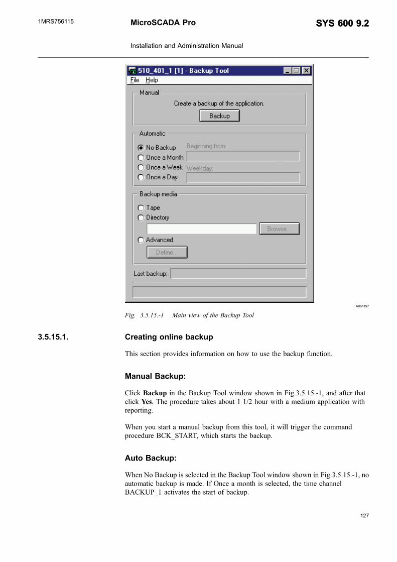
127
A051197
Fig. 3.5.15.-1 Main view of the Backup Tool
3.5.15.1. Creating online backup
This section provides information on how to use the backup function.
Manual Backup:
Click Backup in the Backup Tool window shown in Fig.3.5.15.-1, and after thatclick Yes. The procedure takes about 1 1/2 hour with a medium application withreporting.
When you start a manual backup from this tool, it will trigger the commandprocedure BCK_START, which starts the backup.
Auto Backup:
When No Backup is selected in the Backup Tool window shown in Fig.3.5.15.-1, noautomatic backup is made. If Once a month is selected, the time channelBACKUP_1 activates the start of backup.
MicroSCADA Pro
Installation and Administration Manual
SYS 600 9.2SYS 600 9.21MRS756115

If Once a week is selected, the BACKUP_2 activates the start of backup, and ifOnce a Day is selected then BACKUP_3 activates the start of backup.
As default, the time channels are started as shown in Table 3.5.15.1.-1. If there is aneed to change the time, it can be done with the Time Channel Tool, which isopened from the application object navigator.
Table 3.5.15.1.-1 Backup time channels
BACKUP_1 First day every month at 00:10 (once amonth)
BACKUP_2 Every Friday at 18:01 (once a week)
BACKUP_3 Every day at 00:10 (once a day)
Backup Media:
It is possible to select where the application backup is created. When you select theTape, it will be the Windows Backup, which creates a backup of the backupapplication to a tape.
If the Directory is selected, the backup application is copied in that directory. Thedirectory definition should be in the operating system format.
If Advanced is selected, it is possible to define a SCIL program, which creates thebackup.
A051198
Fig. 3.5.15.1.-1 Example of a advanced backup definition.
General:
When Backup has been started, this tool can follow the shadowing of the mainapplication to the backup application.
128
SYS 600 9.2SYS 600 9.2 MicroSCADA Pro
Installation and Administration Manual
1MRS756115
129
When the shadowing is ready, and the backup creation command has been executed,it shows the following message, "Shadowing is ready. Backup will be created byoperating system".
This means that this tool does not have any connection to the creation of the backup,which is normally made by the operating system tools like Windows Backup.
In the lower part of the tool dialog, there is an info bar, which shows differentsystem messages. One of the fields shows when the last backup has been made.
During the installation, the standard template file, sys_bascon.bck, to be usedtogether with online backup functionality is installed into the \sys\active\sys_ folder.
3.5.15.2. Configuring Backup Tool
The configuration of Backup Tool requires the following steps:
1. Stop MicroSCADA
2. Copy the Sys_Bascon.bck to be the Sys_Bascon.com. The following definitionsin Sys_Bascon.com are important for the shadowing and backup procedures. SeeSys_bascon.bck in \sys\active\sys_ folder.
3. Define the system node name, main application name and application numbers.
Normally the main and watchdog application can be the same.
@SYSTEM = "SYS_A ; System node name or TCP/IP address@APL_NAME = "TUTOR" ; Name of main application@APL_NUMS = (1,1,3) ; Application numbers in the following order:(Main, Watch-dog, Backup), application number must be <= 10
Base system shadowing must be set in use:
#CREATE SYS:B = List(-SA = 209,- ; Station address of base systemND = 9,- ; Node number of base systemSH = 1,- ; SHADOWING ENABLEDDN = 1,- ; Default NET node number
...
LAN link is needed:
#CREATE LIN:V = LIST(- ; Link to other SYS or LAN frontend (requiresTCP/IP)LT = "LAN") ; Link type#CREATE LIN2:B = %LIN
Base system node is needed:
#CREATE NOD:V = LIST(- ; Node for Base SystemNN = %System,-LI = 2,-SA = 209)#CREATE NOD9:B = %NOD
* Main and watchdog applications must have at least 2 parallel queues.* Main and backup applications must have the shadowing attributes defined
correctly.
MicroSCADA Pro
Installation and Administration Manual
SYS 600 9.2SYS 600 9.21MRS756115

* Main and watchdog applications must be set to HOT state, and the backupapplication to COLD.
* Application mapping must be made in main, watchdog and backupapplications.
#CREATE APL:V = LIST(- ; ** Main Application **TT = "LOCAL",- ; Translation TypeNA = %APL_NAME,- ; Name of application directoryAS = "HOT",- ; Application state (COLD, WARM, HOT)PQ = 2,- ; Number of parallel queuesSN = %APL_NUMS(3),- ; SHADOW APPLICATIONSW = %APL_NUMS(2),- ; SHADOW WATCHDOGSC = 240,- ; SHADOW MAXIMUM CONNECTION TIME IN SECONDS
...#LOOP_WITH I = 1 .. LENGTH(%APL_NUMS)@NUM = %APL_NUMS(%I)#SET APL:VAP(%NUM) = %NUM#LOOP_END
This watchdog application is not needed, if the main and watchdog applications arecombined by selecting the watchdog application number to be the same as for themain application in vector "@APL_NUMS", in the beginning of the Sys_Bascon.com.
#CREATE APL:V = LIST(- ; ** Watch dog Application **TT = "LOCAL",- ; Translation TypeNA = "WD",- ; Name of application directoryAS = "HOT",- ; Application state (COLD,WARM,HOT)PQ = 2,- ; Number of parallel queues
...#LOOP_WITH I = 1 .. LENGTH(%APL_NUMS)@NUM = %APL_NUMS(%I)#SET APL:VAP(%NUM) = %NUM#LOOP_END
4. Create a backup application:#CREATE APL:V = LIST(- ; ** Backup Application **
TT = "LOCAL",- ; Translation TypeNA = SUBSTR("BCK" + %APL_NAME,1,8),-; Name of application directoryAS = "COLD",- ; Application state (COLD, WARM, HOT)SN = %APL_NUMS(1),- ; Shadow application = Main applicationSW = %APL_NUMS(2)- ; Shadow watchdog
...#LOOP_WITH I = 1 .. LENGTH(%APL_NUMS)@NUM = %APL_NUMS(%I)#SET APL:VAP(%NUM) = %NUM#LOOP_END
5. Create a backup application with the MicroSCADA control panel.
6. Set the name to BCK, plus five first characters of the main application name (seethe backup application definition in Sys_Bascon.com).
The name can also be something else, but it has to be the same as defined in theSys_Bascon.com file.
7. Start MicroSCADA.
8. Enter a Base system tool picture and select Base Object, (SYS), then selectTools>HSB Management. Check if the shadowing object manager is installed.If not, Click Install to install package.
This will create all the command procedures needed for the shadowingmanagement.
9. Enter this backup tool and select File > Save. Then it asks you to modify thebackup command procedure name from SHADBACKUP to BCK_CREATE.
130
SYS 600 9.2SYS 600 9.2 MicroSCADA Pro
Installation and Administration Manual
1MRS756115

131
This creates the line @BCK_PROC = "BCK_CREATE" in the SHADGLOBALcommand procedure.
10.Select File > Save again, and it asks you to create the following objects:BCK_START:CBCK_CREATE:CBACKUP_1:TBACKUP_2:TBACKUP_3:T
3.5.15.3. Testing new configuration
A new configuration can be tested as follows:
* Click the Backup button and check that the shadowing function is workingcorrectly.
* Select Base system from the tool picture and check that the shadowing onapplications is sending and transmitting correctly.
* Watch the Notify window in case there are some error messages.* If something has gone wrong and the shadowing does not stop, change the
shadowing state in the Basesystem Configuration Tool to "NONE" for both mainand backup application.
3.5.16. Uninstalling MicroSCADA
At the moment there is no uninstall program in MicroSCADA releases. Thefollowing items have to be deleted when uninstalling MicroSCADA.
Please note that the control set numbering may vary in differentcomputers.
Delete the following:
1. \sc directory (and subdirectories)
2. Service (only, if CAP 50x/SMS510 are not installed into the same computer,otherwise those products do not work)
(KEY_LOCAL_MACHINE\SYSTEM\CurrentControlSet\Services\MicroSCADA)
(HKEY_LOCAL_MACHINE\SYSTEM\ControlSet001\Services\MicroSCADA)
(HKEY_LOCAL_MACHINE\SYSTEM\ControlSet003\Services\MicroSCADA)
Use uninstall program of the services, if possible
3. MicroSCADA group from start menu
4. Shortcut to MicroSCADA group on desktop
5. Following fonts from Windows font directory:
MicroSCADA Pro
Installation and Administration Manual
SYS 600 9.2SYS 600 9.21MRS756115

scada0810.fon
scada1215.fon
scada1620.fon
scada2025.fon
scalo0810.fon
scalo1215.fon
scalo1620.fon
scalo2025.fon
abb10.fon
abb14.fon
abb18.fon
6. Package & Product information from registry:
HKEY_LOCAL_MACHINE\SOFTWARE\ABB\PAK\SYS_600\..
KEY_LOCAL_MACHINE\SOFTWARE\ABB\Products\SYS_600\..
7. Driver information from registry:
HKEY_LOCAL_MACHINE\SYSTEM\ControlSet001\Services\...Driver
HKEY_LOCAL_MACHINE\SYSTEM\ControlSet001\Services\EventLog\System\.. Driver
HKEY_LOCAL_MACHINE\SYSTEM\CurrentControlSet\Services\...Driver
HKEY_LOCAL_MACHINE\SYSTEM\CurrentControlSet\Services\EventLog\System\...Driver
The drivers are named starting with letters "MiSC" (MiSCAlrm,MiSCRAM...).
8. Misc event log information from registry:(only, if CAP 50x/SMS510 are notinstalled into the same computer, otherwise those products do not work.)
HKEY_LOCAL_MACHINE\SYSTEM\CurrentControlSet\Services\EventLog\Application\MicroSCADA
HKEY_LOCAL_MACHINE\SYSTEM\ControlSet001\Services\EventLog\Application\MicroSCADA
HKEY_LOCAL_MACHINE\SYSTEM\ControlSet003\Services\EventLog\Application\MicroSCADA
9. Path definitions (this one is needed for older MicroSCADA product versions):
132
SYS 600 9.2SYS 600 9.2 MicroSCADA Pro
Installation and Administration Manual
1MRS756115

133
HKEY_LOCAL_MACHINE\SYSTEM\CurrentControlSet\Control\SessionManager\Environment\ key "MS_SYS"
HKEY_LOCAL_MACHINE\SYSTEM\ControlSet001\Control\SessionManager\Environment\ key "MS_SYS"
HKEY_LOCAL_MACHINE\SYSTEM\ControlSet003\Control\SessionManager\Environment\ key "MS_SYS"
sc\prog\exec from
HKEY_LOCAL_MACHINE\SYSTEM\CurrentControlSet\Control\SessionManager\Environment\ key “Path”
sc\prog\exec from
HKEY_LOCAL_MACHINE\SYSTEM\ControlSet001\Control\SessionManager\Environment\ key “Path”
sc\prog\exec from
HKEY_LOCAL_MACHINE\SYSTEM\ControlSet003\Control\SessionManager\Environment\ key “Path”
Please note the following, when uninstalling MicroSCADA:
* Wserver-process should be killed first. (only, if CAP 50x/SMS510 are notinstalled)
* Starting of Wserver should be removed also from the Startup folder. (only, ifCAP 50x/SMS510 are not installed)
* Service should be uninstalled second. This should be done before deleting sc-directory, because service can be uninstalled with the command "servinst -r".(only, if CAP 50x/SMS510 are not installed)
* MicroSCADA fonts from Exceed -directory should be removed too.* MicroSCADA user should be removed too. (only, if CAP 50x/SMS510 are
not installed)
In the directory HKEY_LOCAL_MACHINE\SOFTWARE\ABB the followingkeys:
HKEY_LOCAL_MACHINE\SOFTWARE\ABB\PAK\SYS_500
HKEY_LOCAL_MACHINE\SOFTWARE\ABB\Products\SYS_500
HKEY_LOCAL_MACHINE\SOFTWARE\ABB\Products\Common\MS-SBASE (this key only if CAP 50x/SMS510 are not installed)
3.6. Verifying SYS 600 startup
Follow this procedure when starting up the entire SYS 600 system:
MicroSCADA Pro
Installation and Administration Manual
SYS 600 9.2SYS 600 9.21MRS756115

1. If not already running, start the process units as described in their respectivemanuals.
2. Start the remote communication equipment, modems, etc.
3. Start the printers by switching the power on.
4. Switch on the workstations, so that MicroSCADA monitors can be openedautomatically.
5. Start the base systems. If there are hot stand-by (redundant) base systems, startboth the hot and stand-by base systems.
6. Start the communication frontends. If there are redundant frontends, start boththe hot and stand-by frontends.
7. Open the MicroSCADA monitors that are not opened automatically.
8. Log into the application.
During the installation of the SYS 600 software, a MicroSCADA Control SystemSYS 600 icon is created, in which you will find links to available tools. Refer to theFig. 3.6.-1 given below.
A070495
Fig. 3.6.-1 Links to available tools
In addition to MicroSCADA kernel software, two empty applications namedTUTOR and WD are also created. You can verify the start ofMicroSCADA SYS 600, MicroSCADA and SYS 600 Pro Monitor without anyfurther editing, by opening the SYS 600 Notify window shown in Fig. 3.6.-2 to seeinformation messages and the possible reasons for failure.
Software revision information is available in the Notification Window.
134
SYS 600 9.2SYS 600 9.2 MicroSCADA Pro
Installation and Administration Manual
1MRS756115

135
A070497
Fig. 3.6.-2 Notification window
More information of installed MicroSCADA software is available in .log files undersc\Setup directoryas shown in Fig. 3.6.-3.
A070741
Fig. 3.6.-3 Revision info
To verify the start of MicroSCADA SYS 600, MicroSCADA and SYS 600 ProMonitor:
1. Open SYS 600 Control Panel.
2. Click Start.
3. Click OK in opened window.
4. Double click MicroSCADA Icon.
5. Log into TUTOR application using the dialog shown in Fig. 3.6.-4 by typing inthe user name and password. For example: tutor, tutor.
MicroSCADA Pro
Installation and Administration Manual
SYS 600 9.2SYS 600 9.21MRS756115

A070496
Fig. 3.6.-4 Tutor application logon dialog
SYS 600 Monitor Pro
To open Monitor Pro locally, double click the SYS 600 Monitor Pro Icon. TheMonitor Pro Login window opens as shown in Fig. 3.6.-5
A070498
Fig. 3.6.-5 Monitor Pro Login dialog
136
SYS 600 9.2SYS 600 9.2 MicroSCADA Pro
Installation and Administration Manual
1MRS756115

137
3.7. SYS 600 Monitor Pro Remote Connection
Pro remote connection means that MicroSCADA Pro monitor is not opened on theSYS but on a separate PC. To establish a connection between MicroSCADA basesystem and workstation on which the Pro type monitor is opened, the followingsteps are needed:
To establish SYS 600 Monitor Pro remote connection:
A070499
Fig. 3.7.-1 Computer management window
1. Create a user to the MicroSCADA Pro server which is running Terminal Servicesand licensing service. Licensing service must be available in the same PC or inthe same network in another PC.
2. Open Computer Management and select Local Users and Group/Users Action/New User as shown in Fig. 3.7.-1.
3. Add created Users to Remote Desktop Users Group in the Remote Desktop UserProperties dialog shown in Fig 3.7.-2.
MicroSCADA Pro
Installation and Administration Manual
SYS 600 9.2SYS 600 9.21MRS756115

A070506
Fig. 3.7.-2 Remote Desktop User Properties dialog
Note: Before starting SYS 600, remember to edit and executeMMC500_TS.cmd which lies under \sc\prog\exec.
138
SYS 600 9.2SYS 600 9.2 MicroSCADA Pro
Installation and Administration Manual
1MRS756115
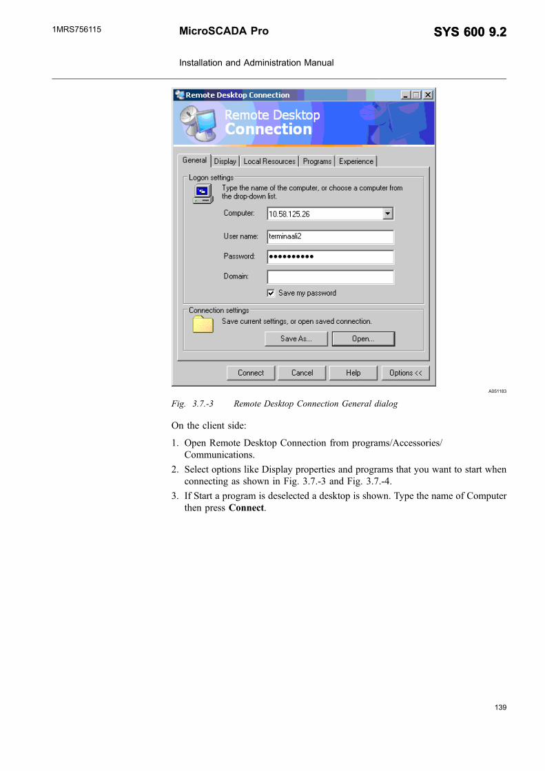
139
A051183
Fig. 3.7.-3 Remote Desktop Connection General dialog
On the client side:
1. Open Remote Desktop Connection from programs/Accessories/Communications.
2. Select options like Display properties and programs that you want to start whenconnecting as shown in Fig. 3.7.-3 and Fig. 3.7.-4.
3. If Start a program is deselected a desktop is shown. Type the name of Computerthen press Connect.
MicroSCADA Pro
Installation and Administration Manual
SYS 600 9.2SYS 600 9.21MRS756115
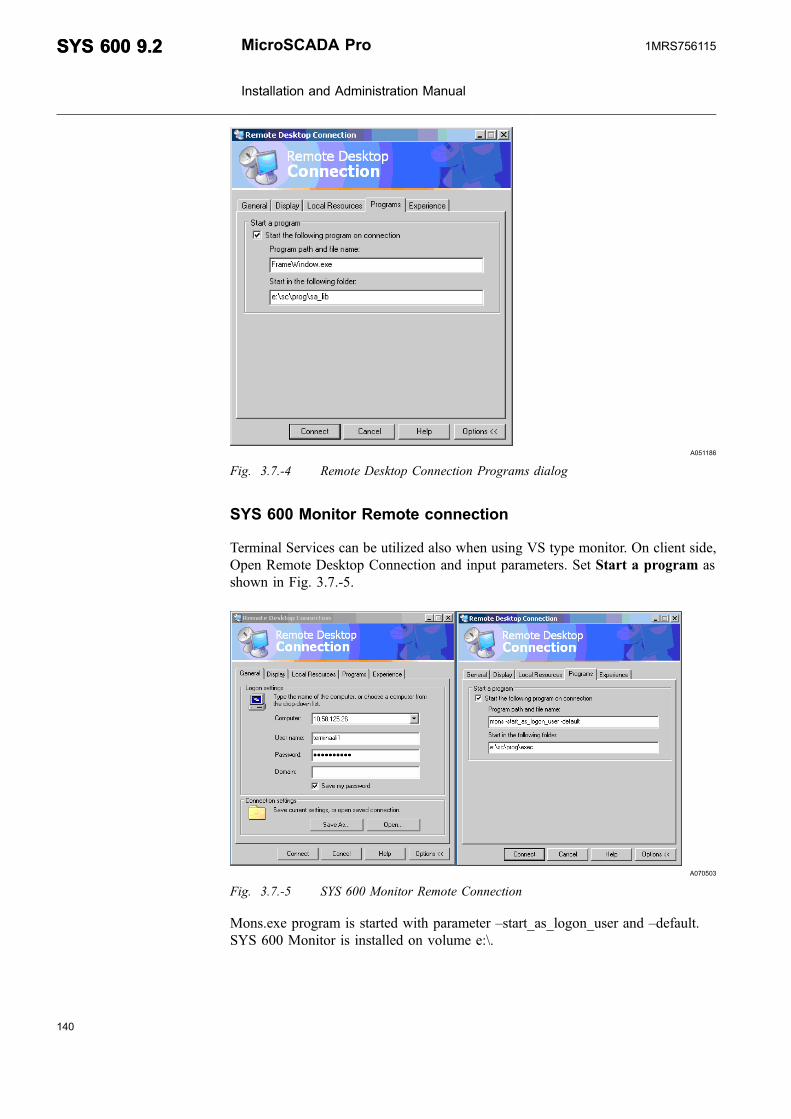
A051186
Fig. 3.7.-4 Remote Desktop Connection Programs dialog
SYS 600 Monitor Remote connection
Terminal Services can be utilized also when using VS type monitor. On client side,Open Remote Desktop Connection and input parameters. Set Start a program asshown in Fig. 3.7.-5.
A070503
Fig. 3.7.-5 SYS 600 Monitor Remote Connection
Mons.exe program is started with parameter –start_as_logon_user and –default.SYS 600 Monitor is installed on volume e:\.
140
SYS 600 9.2SYS 600 9.2 MicroSCADA Pro
Installation and Administration Manual
1MRS756115

141
4. Upgrading from earlier revisionsThis chapter describes upgrading information related to the base system,communication system and LIB 500 system.
Previous and current program packages available for MicroSCADA usage areshown in Table.4.-1.
Table 4.-1 Previous and current program packages available for usage
SYS revision Base LIB revision Application library revision
SYS 600 LIB 500 4.2 LIB 510 4.2LIB 520 4.1LIB 530 4.0.4LIB 542 4.0.5
LIB 500 4.1 LIB 510 4.1LIB 520 4.1LIB 530 4.0.4LIB 542 4.0.5
SYS 500 8.4.4 SP1 or newer LIB 500 4.2 LIB 510 4.2LIB 520 4.1LIB 530 4.0.4LIB 542 4.0.5
LIB 500 4.1 LIB 510 4.1LIB 520 4.1LIB 530 4.0.4LIB 542 4.0.5
LIB 500 4.0.5 LIB 510 4.0.5LIB 520 4.0.4LIB 530 4.0.4LIB 542 4.0.5
SYS 500 8.4.4 or newer LIB 500 4.0.4 LIB 510 4.0.4LIB 520 4.0.4LIB 530 4.0.4LIB 542 4.0.4
Application Libraries:
* LIB 510 Application Library for Medium Voltage process* LIB 520 Application Library for High Voltage process* LIB 530 Application Library for High Voltage process* LIB 542 Application Library for Medium Voltage process
4.1. Base system
From the base system point of view, no modifications to the application are requiredto start it after the installation. However, there are some issues to be considered tomake the application work exactly as before (or better):
MicroSCADA Pro
Installation and Administration Manual
SYS 600 9.2SYS 600 9.21MRS756115

* The configuration file templates SYS_BASCON$COM, SYS_BASCON.HSB,SYS_CONFIG$PAR and SHUTDOWN$CIN should be merged to thecorresponding old application files SYS_BASCON.COM, SYS_CONFIG.PARand SHUTDOWN.CIN to enable new features introduced in newer revisions.The configuration files are described in the System Configuration manual.
* During the development of the product some errors have been fixed in a way thatmay have influence on the old applications that have relied on the error. Inaddition, the default behavior in some situations, often related to event and alarmhandling, have been changed. The Revision Compatibility mechanism,implemented as the RC attribute of the application object (see the SystemObjects manual) and the REVISION_COMPATIBILITY function (see theProgramming Language SCIL manual), may be used to keep the old behavior.
In the following sections, the most important revision compatibility switches to beconsidered at the upgrade are described. They are listed in the reverse order of therevision of the old system. For example, if the system is upgraded from 8.4.3 to 9.2,the sections down to 4.1.3 are relevant.
If the system to be upgraded is running an operating system other than Windows(Unix or iRMX), please consult our SA-D Support Line for the details of theupgrade.
4.1.1. Mirroring considerations
If mirroring is used in the system to be upgraded, it is recommended that theMicroSCADA Pro Hotfix MSH07-001 is applied after the installation of SYS 6009.2.
If the system works as a mirroring host and any of its images run revision 8.4.5 orolder, the hotfix is mandatory to even make the mirroring work.
If the system to be upgraded is or is going to be a part of a mirroring network, thecompatibility switch "844_COMPATIBLE_MIRRORING" must be set in thefollowing two cases:
* There is a system running revision 8.4.4 in the network.* "844_COMPATIBLE_MIRRORING" is set in the other systems of the network.
844_COMPATIBLE_MIRRORING
Mirroring between revision 8.4.4 and any later revision does not work when defaultsettings are used. When upgrading from 8.4.4, both the host system and the imagesystem has to be upgraded to make mirroring work again.
Compatibility switch "844_COMPATIBLE_MIRRORING" has been implementedto make it possible to upgrade systems of the mirroring network one by one.
142
SYS 600 9.2SYS 600 9.2 MicroSCADA Pro
Installation and Administration Manual
1MRS756115

143
When "844_COMPATIBLE_MIRRORING" is set (in revision 8.4.5, or later), themirroring works with an 8.4.4 application, and also with a newer application thathas specified "844_COMPATIBLE_MIRRORING". However, it does not workwith an 8.4.5 or later application without "844_COMPATIBLE_MIRRORING".
Using "844_COMPATIBLE_MIRRORING", the upgrading can be done system bysystem without disturbing the operation of the network. In this case, each new nodethat is added to the network later must set "844_COMPATIBLE_MIRRORING" aswell.
The setting of "844_COMPATIBLE_MIRRORING" does not affect thefunctionality of the program or cause any decrease in performance.
4.1.2. Upgrading from revision 8.4.5 SP1 or 9.0
COUPLE_AUDIO_ALARMS_AND_PRINTOUTS
Generation of audio alarms has been changed in SYS 600 revision 9.1 and inSYS 500 revision 8.4.5 SP2. Audio alarms and alarm printouts are now generatedindependently of each other. In earlier revisions, an audio alarm was generated onlywhen an alarm row was printed on the event printer.
When "COUPLE_AUDIO_ALARMS_AND_PRINTOUTS" is set, the audioalarms of the application are generated as in earlier program revisions.
4.1.3. Upgrading from revision 8.4.3
DONT_RECALCULATE_AL_AFTER_ALARM_BLOCKING
Since revision 8.4.4, the alarm state is recalculated when AB is set back to 0.However, neither alarm printouts nor event channels are activated (they are notactivated when AB is set to 1, neither).
"DONT_RECALCULATE_AL_AFTER_ALARM_BLOCKING" may be set if theapplication, for a reason or another, does not want this new behaviour.
NO_ALARM_BY_OR_AND_OF
Since revision 8.4.4, the protocol specific attribute OR (Out of Range) and OF(Overflow) value 1 generate an alarm (cf. OS value 1, or FAULTY).
"NO_ALARM_BY_OR_AND_OF" may be set if the application, for a reason oranother, does not want this new behavior.
MicroSCADA Pro
Installation and Administration Manual
SYS 600 9.2SYS 600 9.21MRS756115
DEFAULT_DAYLIGHT_POLICY_IS_CALENDAR
In revision 8.4.4, the implementation of time handling was comprehensivelyrewritten. Both local and UTC time as well as daylight saving time are fullysupported. There is a slight incompatibility between the new and oldimplementation of the scheduling of time channels: The default behaviour of timechannels at daylight saving time / standard time transitions has been changed.
Prior to revision 8.4.4, the scheduling of time channels was synchronized to thelocal time of the system. When the local time was moved backwards at daylightsaving to standard time transition, the time channels stopped for an hour.Correspondingly, at standard to daylight saving time transition, the time channelswere excessively scheduled.
In revision 8.4.4, the default behaviour is that the time channels are scheduledevenly (synchronized to UTC time) when the local time changes due to daylightsaving and there is a new attribute DP (Daylight Switch Policy) to specify thebehaviour, see the manual “Application Objects”.
When "DEFAULT_DAYLIGHT_POLICY_IS_CALENDAR" is set, the timechannels created with earlier program revisions keep behaving as before. Evenscheduling is the default behaviour of new time channels, however.
ALLOW_CONFLICTING_F_ATTRIBUTE_NAMES
When a pre-8.4.3 application is upgraded to 8.4.5 or later, the creation of F (FreeType) objects fails by PROF_FREE_ATTRIBUTE_NAME_ALREADY_EXISTS(2212), if the F object defines attribute names implemented as common processattributes in the base system in revisions up to 8.4.4. Examples of such conflictingattributes are RB, TI, TY, OI, BL, RB, OR and CT.
When "ALLOW_CONFLICTING_F_ATTRIBUTE_NAMES" is set, suchconflicting attribute names are accepted when an F object is created.
This switch should be used only when an old application is upgraded, because thenew base system functionality implemented by conflicting attributes will be lostwhen the name is overloaded. In addition, some common SCIL tools (such as theObject Navigator) and other SCIL software may be confused when the data type andmeaning of some common attributes are not that expected.
4.1.4. Upgrading from revision 8.4.2
NO_QUALITY_ATTRIBUTE_SEMANTICS
In revision 8.4.2 and earlier, the quality attributes SB (Substituted), BL (Blocked),OR (Out of Range) and OF (Overflow) have been information-only attributes, i.e.they have been stored in the process object to be available for SCIL but their valueshave not affected the behavior of the process object in any way.
144
SYS 600 9.2SYS 600 9.2 MicroSCADA Pro
Installation and Administration Manual
1MRS756115

145
In newer revisions the following rules apply:
* A change of a quality attribute generates an event if EE = 1* A change of a quality attribute activates an event channel, a printout and/or
history logging if the activation is enabled (AE == 1, LD <> 0 or HE == 1) andthe activation criterion (AA, PA or HA) is "NEW VALUE" or "UPDATE".
* In such activation, the changed attribute is reported as the value of CA pseudo-attribute. If more than one attribute is changed at the same time, each change willbe reported separately in any order. For example, if OV changes from 0 to 1 andSB from 1 to 0, two activations occur, one with CA == "BI", BI == 1 and SB ==0, the other with CA == "SB", BI == 1 and SB == 0.
* When the switch state (SS) or the substitution state (SU) of the object is changed,the quality attributes are set to 0.
When "NO_QUALITY_ATTRIBUTE_SEMANTICS" is specified, the qualityattributes behave as in revision 8.4.2 and earlier.
4.1.5. Upgrading from revision 8.4.1
NO_ALIAS_CHECKING
Since revision 8.4.2 global variables are guarded against alias references. StatusSCIL_VARIABLE_ALIASING_ERROR is generated when aliasing rules areviolated.
When "NO_ALIAS_CHECKING" is set (either by the RC attribute of theapplication or by REVISION_COMPATIBILITY function), alias checking is notdone. Turning on the switch by the RC attribute disables the checking of aliasreferencing in the whole application. To disable the alias reference checking locallyin a program, use the REVISION_COMPATIBILITY function. TheREVISION_COMPATIBILITY function is described in the “ProgrammingLanguage SCIL” manual.
The arguments of method calls, as well as all the arguments of SCIL functions, arepassed by copy instead of reference. This degrades performance when text, bitstring, byte string, vector and list arguments are used.
If the base system will be used together with applications created with pre-8.4.2revisions of the base system, e.g. using LIB 4.0.1, the revision compatibility switchNO_ALIAS_CHECKING should be turned on.
MicroSCADA Pro
Installation and Administration Manual
SYS 600 9.2SYS 600 9.21MRS756115

4.1.6. Upgrading from revision 8.4.0
SETTING_LA_AND_AG_DOES_NOT_ALARM
In revision 8.4.0 and earlier, setting AG or LA attribute of a process object did notaffect the alarm state of the object and no post-processing was done. Since revision8.4.1, the alarm state is updated according to the new value and normal post-processing is done. Due to the change, some old applications generate unwantedalarms and printouts when run under 8.4.1 or later. To prevent this, this revisioncompatibility value was implemented.
The value can be used only as the value of the application attribute RC. It cannot beused as an argument of SCIL function REVISION_COMPATIBILITY, becauseevent handling is done by the process database.
4.1.7. Upgrading from revision 8.2
DO_NOT_SYNCHRONIZE_PICTURE_UPDATE
The timing of update programs of pictures is synchronized to the system clock (Seethe Programming Language SCIL manual, command !UPDATE). In revision 8.2 (orolder), such a synchronization was not done. When an old application that relies onthe old behavior is upgraded, this setting may be used to avoid recoding of thepictures.
When "DO_NOT_SYNCHRONIZE_PICTURE_UPDATE" is set, the executions ofupdate programs are not synchronized. This setting does not affect the cyclicmethods of Visual SCIL objects.
4.1.8. Upgrading from revision 8.1
ON_COMMAND_EXPANSION
In revision 8.1 or older, the 'macros' of each SCIL command line were expandedbefore the line was interpreted. This lead to an incorrect behavior in case of a singleline #ON command, as shown in the following example:
@A = "XYZ"
#ON EVENT:E1 #EXEC 'A':E2
When event EVENT:E1 occurred, command "#EXEC XYZ:E2" was executedregardless of the current value of A. Variable expansion is a run-time operation,which should use the current values of variables. The following worked correctly:
#ON EVENT:E1 #BLOCK #EXEC 'A':E2 #BLOCK_END
146
SYS 600 9.2SYS 600 9.2 MicroSCADA Pro
Installation and Administration Manual
1MRS756115

147
When "ON_COMMAND_EXPANSION" is set, the expansion of macros is done asin revision 8.1, that is, before the line is interpreted.
4.2. LIB 5xx
Language translation
When LIB 5xx is updated there might be new attributes in language text files. Thismeans that those attributes has to be added and translated to corresponding localizedlanguage files.
Revision compatibility switches
If only base system is updated and LIB 5xx is from earlier revision, somemalfunction may occur in LIB 5xx application. This situation can be handled bymeans of revision compatibility switches. In this chapter the relation of revisioncompatibility switches having influence to LIB 5xx applications is explained. Formore information about revision compatibility switches refer to Section 4.1. Basesystem.
NO_ALIAS_CHECKING
If SCIL_VARIABLE_ALIASING_ERROR is generated turn this switch
DONT_RECALCULATE_AL_AFTER_ALARM_BLOCKING
If base system is 8.4.4 or newer and LIB5xx application is revision 4.0.3 or oldereach switch device control action generated an alarm. This can be avoided byturning this switch on.
Daylight saving time
When LIB 500 is updated to revision 4.0.4 or latter a new daylight saving timemechanism is taken into use. Command procedures (BGU_SUMMER,BGU_WINTER) and related time channels handling the daylight saving time in a"old" way are disabled. A back up of the command procedures is stored to filesPICT/BGU_SUMMER.CIN and PICT/WINTER_SUMMER.CIN
MicroSCADA Pro
Installation and Administration Manual
SYS 600 9.2SYS 600 9.21MRS756115

4.3. Monitor Pro
4.3.1. Common applications with LIB 5xx
SYS 600 revision 9.2 contains the User Management, Calendar and Login Dialogintegrated from LIB 500 to SYS 600. By default, the user name and password arerequested for the applications. If the application has not been previously preparedfor the LIB 500 User Management, then the first operator who logs into applicationwill be the System Manager.
By default, the User Management, Calendar and Login Dialog, are run from PowerProcess Library. This is applied also when the application has been prepared for theLIB 500.
For the Login Dialog, the authentication has become more strict. This means thatpasswords are case sensitive, i.e. passwords that have been created with SYS 600revision 9.1 or older must be typed with upper case letters.
Defining application specific login picture
When opening classic monitor, the first visible object can be defined in file \sc\apl\'aplname`\ APL_\Apl_Def.txt. This option can be used when application specificlogin dialog is opened or user login is not wanted at all. For example, the logindialog from LIB4 can be taken in use by doing the following:
1. Copy BGU_LOGIN.VSO from LIB4/BASE/BBONE/USE to APL/'APLNAME'/APL_
2. Make this definition to Apl_Def.txt;define starting picture@i_monitor_number = mon:ban#if mon'i_monitor_number':bcx == "<LIB500/INVISIBLE_MONITOR>"#then#block;This monitor is reserved for the relay tools. Monitor is invisible@Start_Object_Type = "Dialog" ;Defines the fist object as a VS dialog@Start_Dialog_File = "b_use/bgu_invisible_mon.vso";Needed if Start_Object_Type == "Dialog"@Start_Dialog_Tag = "Main" ;Needed if Start_Object_Type == "Dialog"@Start_Dialog_Type = "VS_Main_Dialog" ;Needed if Start_Object_Type == "Dialog"
#block_end
#else_if MON:BDT<>"VS"#then#block@Start_Object_Type = "Picture" ;Defines the fist object as a picture@Start_Picture_Name = "APL_START" ;Needed if Start_Object_Type == "Picture"
#block_end
#else#block@Start_Object_Type = "Dialog" ;Defines the fist object as a VS dialog@Start_Dialog_File = "b_use/bgu_login.vso";Needed if Start_Object_Type == "Dialog"@Start_Dialog_Tag = "Main" ;Needed if Start_Object_Type == "Dialog"@Start_Dialog_Type = "VS_Main_Dialog" ;Needed if Start_Object_Type == "Dialog"
#block_end
In order to have Tool Manager as a first picture make the following definition:
@Start_Object_Type = "Dialog" ;Defines if the first object is a picture or VS dialog@Start_Picture_Name = "APL_START" ;Needed if Start_Object_Type == "Picture"@Start_Dialog_File = "Sys_Tool/ToolMgr.vso";Needed if Start_Object_Type == "Dialog"
148
SYS 600 9.2SYS 600 9.2 MicroSCADA Pro
Installation and Administration Manual
1MRS756115

149
@Start_Dialog_Tag = "Main" ;Needed if Start_Object_Type == "Dialog"@Start_Dialog_Type = "VS_Main_Dialog" ;Needed if Start_Object_Type == "Dialog"@Start_Dialog_Attributes= vector("Default_Path=""Sys_Tool""","Notify_Parent_On_Exit = false","Delete_Parent_On_Exit=true")
Filters
In SYS 600 9.2 the Event and Alarm List filters must be in predefined directory,whereas in 9.0 and 9.1 it was possible to store the filter files anywhere in thedirectory structure. When updating to 9.2, the filter files must be moved to directory\sc\apl\<application name>\PAR\<user name>\FILTERS, otherwise they are notshown in Save/Load Filter dialog.
Command procedures
Monitor Pro functionality uses some command procedures to communicate withbase system. These command procedures are overwritten during the update fromprevious versions. If there are any modifications done to these command proceduresthese changes will be overwritten during the update. To avoid this, the code of thecommand procedures should be copied manually into text files. Followingcommand procedures are overwritten during the update:
ACK_SOUNDBGU_ALBGU_ALARMINDSBGU_BAYLRBGU_BLOCKBGU_CALENBGU_CALMPBGU_CONTROLBGU_CREATEDBBGU_EL_TSBGU_RDREBGU_STALRBGU_SUMMERBGU_TRAFOBGU_WINTERSAGR_EAB_MAINSAGR_OBJNAV_MAINSAGR_REPORTS
Process objects
Following process objects are re-created during the installation:
ACK_SOUNDBGU_ALARMINDS (indexes 1..10)
Event handling objects
Also certain event handling are re-created. Modifications made to these objects arealso lost. To avoid loosing such changes, use Import/Export Tool (can be found inTool Manager) to export the objects and import them back after installation. Thename of these event handling objects start with letters "SAGR".
MicroSCADA Pro
Installation and Administration Manual
SYS 600 9.2SYS 600 9.21MRS756115

Starting MicroSCADA Pro without preparation for Power ProcessLibrary
If MicroSCADA is wanted to run without Power Process Library do the followingactions after version 9.2 is installed and before starting MicroSCADA.
1. Comment SYS_600 specific part from the file \sc\sys\active\sys_\sys_bascon.com
2. Comment SYS_600 specific part from the file \sc\Stool\Misc\Apl_Stl.txt
3. Rename file \sc\sa_lib\base\bbone\inst\INDEX5_B1.TXT to e.g. _INDEX5_B1.TXT
4. Rename file \sc\LIB4\base\bbone\use\PATH4_Z1.TXT to e.g. _PATH4_Z1.TXT
4.4. Communication units
In principle, the process communication unit PC-NET, Modbus Slave and CDC-IIslave can be upgraded to a newer version without changes in the system behavior.This chapter provides additional information related to the upgrading of IEC 61850and External OPC Data Access Client.
If the system to be upgraded contains DCP-MUX units, they must be replaced withPC-NET process communication units. In this situation, it must be checked that allrequired protocols are supported by the PC-NET. Furthermore, the configurationused in DCP-MUX units must be loaded to corresponding PC-NET units with thesystem configuration tool or with a SCIL-script. Generally, the same attribute valuesfor line and station objects can usually be used. Upgrading from DCP-MUX toPC-NET requires changes in serial port hardware.
The list of the protocol implemented to DCP-MUX and supported by the currentversion of PC-NET:
(value refers to line attribute PO)
PO value Protocol
1 ANSI X3.28 Full Duplex or ACP
2 ANSI X3.28 Half Duplex
4 ASCII protocol for printer (or printersimulating device)
7 RP570 master protocol
9 P214 protocol
12 LCU500
13 ADLP180 Master
14 SPA protocol
15 General ASCII
16 RP570 Slave
17 RCOM (Procontic)
18 Westinghouse F4F
23 ABB Alpha meter protocol
24 General PLC protocol
150
SYS 600 9.2SYS 600 9.2 MicroSCADA Pro
Installation and Administration Manual
1MRS756115

151
Table 4.-1 Previous and current program packages available forusage (Continued)
PO value Protocol
25 Modbus RTU master protocol
26 IEC 1107 protocol
If the DCP-MUX to be upgraded contains a protocol which is not listed here, theupgrading is not possible as such. In this situation, please contact SA-D SupportLinefor more information.
4.4.1. PC-NET
The main issue in the development tasks made to pc_nets.exe is to retain backwardcompatibility from revision to another. This principle applies also to protocolsdeveloped already to DCP-MUX hardware.
However, the differences in processor speeds, operating system versions andcommunication hardware together with new requirements in system setups andsecurity will require that the system behavior must be verified after the upgrade.Before the upgrade, please read through the backward incompatibility items listedbelow. The listed PC-NET related issues are protocol specific and if the system to beupgraded does not contain mentioned protocols, the item has no effect in theupgrade. More information about the mentioned attributes can be found fromprotocol specific manuals and System Objects manual
If the behavior of a communication line after the upgrade is not satisfactory, attributechanges to the system configuration may be required. A systematic proceeding inthe problem analysis usually gives best results, sometimes it is needed to record acommunication log from the line which is causing problems.
4.4.1.1. PC-NET from SYS 600 9.1 (COM 500 4.2)
In this case, there will be neither backward compatibility issues nor changes insystem requirements.
MicroSCADA Pro
Installation and Administration Manual
SYS 600 9.2SYS 600 9.21MRS756115

4.4.1.2. PC-NET from SYS 500 8.4.x
If the previous version is SYS 500 8.4.5 SP1, SYS 500 8.4.4 SP4, SYS 600 9.0,COM 500 4.0 SP1 or older, following upgrade notification must be taken intoaccount:
* After the upgrade, each instance of PC-NET will allocate 16 Megabytes ofmemory. PC-NET instance in versions SYS 500 8.4.4 SP1, COM 500 4.0(without service packs) and older allocated 4 Megabytes of memory. In versionsCOM 500 4.0 SP1, SYS 500 8.4.5 SP1, SYS 500 8.4.4 SP4, SYS 600 9.0 orolder but newer than SYS 500 8.4.4 SP1 the allocated amount is 8 Megabytes. Inprinciple, the usage of a newer version may lead to lack of memory if thecomputer resources stay unchanged in the upgrade.
If the previous version is SYS 500 8.4.4 (without service packs), COM 500 4.0(without service packs) or older, following upgrade notification must be taken intoaccount:
* In DNP 3.0 slave protocol, the response handling of an incoming class 1/2/3/0request from the DNP 3.0 master is handled differently and order of thedatapoints in the response is different. It is possible that the new behaviour canbe seen in the process pictures of the master also.
If the previous version is SYS500 8.4.3 SP3, COM 500 3.0 SP1 or older, followingupgrade notifications must be taken into account:
* In IEC60870-5-101 slave protocol, the RM attribute bit 4 of station objectcontrols the acceptance of the incoming control commands from the master. Inthe newer version the default behaviour is that a execute command is notaccepted without preceding select. The behavior stays unchanged if bit 4 of theattribute RM is set, see corresponding manual for more information.
* In IEC60870-5-101 slave protocol, the TC attribute of the station object controlsthe handling of the incoming time synchronization. In the newer version thedefault value is 1 which causes the message contents to be sent to a processobject also. See corresponding manual for more information.
* In any serial protocol, the line attribute RY presented in version 8.4.4 alsocontrols the behaviour of the RTS-signal of the RS-232 port. For RocketPortserial cards, the default value RY=1 will cause the RTS signal to be active onecharacter longer compared with the previous version. This is usually harmless.With setting RY=0 the behaviour is unchanged with RocketPort. With a standardserial port of PC, the behaviour is unchanged with setting RY=1 and dependingon the used modem hardware, setting RY=0 does not necessarily work at all.
If the previous version is a DCP-MUX unit and the needed protocols can be foundfrom the list presented in Section 4.4. Communication units, the upgrading ispossible. The existing line and station attribute configuration must be converted to aSCIL script if the DCP-MUX has been configured with a NETCONF program. TheDCP-MUX card is replaced with a multi-port serial card.
152
SYS 600 9.2SYS 600 9.2 MicroSCADA Pro
Installation and Administration Manual
1MRS756115

153
4.4.1.3. PC-NET from SYS 500 8.x
If the needed protocols can be found from the list presented in Section 4.4.Communication units, the upgrading of the DCP-MUX unit to PC-NET should bepossible. The DCP-MUX card is replaced with a multi-port serial card havingsufficient amount of COM-ports. The connected RS232-devices like modems canusually be used as such. The existing line and station attribute configuration must beconverted to a SCIL script if the DCP-MUX has been configured with a NETCONFprogram.
4.4.2. IEC 61850
Migration of Communication Engineering Tool (CET)configurations before usage
If the IEC 61850 CET project has been originally made with SYS 600 revision 9.0or 9.1, and the appropriate configuration will be now taken in use in SYS 600revision 9.2, the following steps are needed to migrate the project.
Before installing the SYS 600 revision 9.2 take a copy of your {guid}.xml files. Forexample:
23a247e6-7552-4c58-a202-eff8693f372f.xml from drive>:\sc\prog\61850_OPC_Server\CET\bin\Tools\OPCSCLExport.
After finalising the SYS 600 revision 9.2 installation, create both a new databaseand an IEC 61850 OPC Server to CET. Use SCLImport tool and import yourexisting configuration from the {guid}.xml file. A {guid} example included intoabove is an example of such a code, the {guid} in your projects, i.e. related .xmlfiles differs from the example given above.
To successfully use the CET you will need 'Full Access' access rights to be assignedfor everyone to the following folders:
<drive>:\PCMDATABASES (location depends on Environment VariablePCMDATADIR )
<drive>:\sc\prog\61850_OPC_Server\CET\bin
<drive>:\sc\prog\61850_OPC_Server\CET\bin\Tools\OPCSCLExport
The reason for this migration is that the CET databases in SYS 600 revision 9.0/9.1and revision 9.2 are not fully compatible.
When existing CET configurations are taken in use with SYS 600revision 9.2, it is important to also verify that the correct configurationattribute values will be taken in use by your IEC 61850 project. Seefurther information in IEC 61850 System Design manual, chaptersTimeout handling and Troubleshooting.
MicroSCADA Pro
Installation and Administration Manual
SYS 600 9.2SYS 600 9.21MRS756115

4.4.3. Modbus slave
Modbus slave is a separate executable used in systems with COM500i. The samebackward compatibility approach is also used with modbus slave . Themodifications made to modbus_slave.exe has been minor and upgrading to a newerversion should not cause problems.
4.4.4. CDC-II slave
CDC-II slave is also a separate executable used in systems with COM500i. Thesame backward compatibility approach is also used with CDC-II slave. Themodifications made to cdcslave.exe has been minor and upgrading to a newerversion should not cause problems. Additional information regarding theconfiguration parameters related to the CDC-II slave can be found from the CDC-IISlave Protocol manual.
4.4.5. External OPC Data Access Client
External OPC Data Access Client is a separate executable used in systems includingdevices communicating via OPC protocol or IEC 61850 systems. Any existingconfiguration can be used in External OPC Data Access Client. The modificationsmade to daopccl.exe has been minor and upgrading to a newer version should notcause problems. Previously, when External OPC Data Access Client was deliveredas a separate installation package for SYS/COM products, the destination folder forthe executable was always <drive>:\MS_Interfaces\OPC_Client. For all theSYS 600 revisions, the installation of External OPC Data Access Client occursalways into folder <drive>:\sc\prog\OPC_Client. Modify the application start-uproutines accordingly to start the latest External OPC Data Access Client executable,when needed. Additional information related to the configuration parameters relatedto the External OPC Data Access Client can be found from the External OPC DataAccess Client and IEC 61850 System Design manuals.
4.5. Communication gateway
4.5.1. Upgrading COM 500 revision 2.0, 3.0, 4.0, 4.1 and 4.2
If an existing COM 500 revision 2.0-4.2 application is updated to COM 500irevision 9.2, please note the following:
COM 500i revision 9.2 has a mechanism that makes all the required modificationsto the application to update an older revision to revision 9.2. This mechanism isstarted when a monitor is opened to a COM 500i application for the first time afterthe installation of COM 500i. After the mechanism has been run, you must restartSYS 600 to take all the modifications in use. Also PQ and QD attributes should bedefined for queue 16 in SYS_BASCON.
SYS_BASCON modifications:
154
SYS 600 9.2SYS 600 9.2 MicroSCADA Pro
Installation and Administration Manual
1MRS756115

155
PQ = 16,- ;Number of parallel queues/ Needed in COM 500 Applications
QD = (1,1,0,0,0,0,1,1,1,1,1,1,1,1,1,1),- ;Parallel queue dedication/ Needed inCOM 500 Applications
If any project specific modifications have been made to the command procedures ofthe previous COM 500 revision, the modifications must be copied to the matchingnew command procedures. A back-up of the project specific modifications must betaken before installation of COM 500i, because all command procedures are updatedduring COM 500i start-up.
Base System, LIB 5xx and Communication unit changes are described inSection 4.1. Base system, Section 4.2. LIB 5xx, and Section 4.4. Communicationunits. The same changes should be also made when COM 500 is updated toCOM 500i. Corresponding of COM 500 and SYS revisions are show in thefollowing table:
Table 4.5.1.-1 Correspondence of COM 500 and SYS revisions
COM 500 revision SYS revision
4.2.SP2 SYS 600 9.1.5
4.2 SP1 SYS 600 9.1 SP1
4.2 SYS 600 9.1
4.1 SYS 600 9.0
4.0 SP1 SYS 500 8.4.4 SP1
4.0 SYS 500 8.4.4
3.0 SP2 SYS 500 8.4.3 SP4
3.0 SP1 SYS 500 8.4.3 SP2
3.0 SYS 500 8.4.3
2.0 SYS 500 8.4.2
4.5.2. Upgrading COM 500ii revision 1.0
For more information about upgrading revision 1.0, refer to the CommunicationGateway, COM 500i User’s Guide.
4.6. Updating device drivers
In general the device drivers are backwards compatible within a major revisionnumber, that is, drivers in 8.4.2 revision is used with Base System Software ofrevisions 8.4.1 and 8.4.0.
When updating to MicroSCADA Pro, the driver packages can be installed from theMicroSCADA Pro software CD or they are included to adapter card package. Thesupported versions of the drivers can also be downloaded from the web sites of therespective manufacturers :
ADLink site: http://www.adlink.com.tw/home.htm
MicroSCADA Pro
Installation and Administration Manual
SYS 600 9.2SYS 600 9.21MRS756115

Advantech site: http://www.advantech.com
Meinberg site: http://www.meinberg.de
DHelectrnics: http://www.xlon.de
156
SYS 600 9.2SYS 600 9.2 MicroSCADA Pro
Installation and Administration Manual
1MRS756115

157
5. Abbreviations
Abbreviation Description
ASCII American Standard Code for Information Interchange
GB Gigabyte
HSB Hot Stand-by
LAN Local area network
MB Megabyte
PCI Peripheral Component Interconnect
RAM Random access memory
SCIL Supervisory Control Implementation Language
TCP Transmission Control Protocol
TS CAL Terminal service client access license
MicroSCADA Pro
Installation and Administration Manual
SYS 600 9.2SYS 600 9.21MRS756115


ABB OySubstation Automation ProductsP.O. Box 699FI-65101 VaasaFINLANDTel. +358 10 2211Fax. +358 10 224 1094www.abb.com/substationautomation
1MRS75611
5EN
10/2007