micrologic 20 70a eng
DESCRIPTION
micrologicTRANSCRIPT
Micrologic control units2.0 A, 5.0 A, 6.0 A and 7.0 ALow Voltage Products
User manual
We do more with electricity.

Micrologic A Schneider Electric1
Discovering your control unit 2Identifying your control unit 2Overview of functions 4
Setting your control unit 10Selecting the type of neutral protection 10Setting procedure 11Setting the Micrologic 2.0 A control unit 12Setting the Micrologic 5.0 A control unit 13Setting the Micrologic 6.0 A control unit 14Setting the Micrologic 7.0 A control unit 15
Fault and status indications 16Resetting the fault indicationsand checking battery status 16Testing the earth-faultand earth-leakage functions 17
Menus 18Accessing the menus 18Measuring phase currents 19Displaying the maximum current values 20Resetting the maximum current values 21Viewing the settings 22
Technical appendix 24Tripping curves 24Changing the long-time rating plug 26Zone selective interlocking (ZSI) 27Digital display 28Thermal memory 29
Micrologic control units2.0 A, 5.0 A, 6.0 A and 7.0 A

Micrologic A Schneider Electric2
Discovering yourcontrol unit
E51
384A
E51
450A
All Compact NS800-3200 and MasterpactNT and NW circuit breakers are equippedwith a Micrologic control unitthat can be changed on site.Control units are designed to protectpower circuits and connected loads.
Identifying your control unitDesignations
E51
352A
X: type of protectionc 2 for basic protectionc 5 for selective protectionc 6 for selective + earth-fault protectionc 7 for selective + earth-leakage protection
Y: version numberidentification of the control-unit generation."0" signifies the first generation.
Z: type of measurementc A for "ammeter"c P for "power meter"c H for "harmonic meter"c no indication: no measurements
Micrologic 2.0 A: basic protection and ammeter
Long time + Instantaneous
Micrologic 5.0 A: selective protection and ammeter
Long time + Short time + Instantaneous
E51
385A
E51
354A
0 Ir Isd I
t
0 Ir I
t
IiIsd
Micrologic 6.0 A: selective + earth-fault protection andammeter
E51
387A
E51
354A
E51
395A
0 Ir I
t
IiIsd
Long time + Short time+ Instantaneous
Earth-fault protection
Micrologic 7.0 A: selective + earth-leakage protection andammeter
E51
388A
E51
354A
E51
452A
0 Ir I
t
IiIsd
Long time + Short time+ Instantaneous
Earth-leakage protection
Micrologic 2.0 A
YX
Z
Micrologic 2.0 A
40
100%
%
menu
long timealarm
instantaneous
.4.5.6
.7.8
.9.95.98
1
Ir
x In .512
48
121620
tr(s)
at 6 Ir24
x Ir
22.5
3 45
6
1.5
setting
Isd
810
Micrologic 5.0 A
40
100%
%
menu
delay
short timetsd(s)
long timealarmtr
(s)
setting
.4.5.6
.7.8
.9.95.98
1
Ir
x In .512
4 8 121620
at 6 Ir24
x Ir
22.5
3 4 568
10
Isd
1.5on I2t
.2
.4 .4
.1
.3
.10
I i
x In
3
4
8
off2
.3
instantaneous
.26
15
1012
Micrologic 6.0 A
40
100%
%
menu
delay
short time
on I2t
.2
.3.4 .4
.1
.2
.10
long timealarm
ground fault
setting
4
test
.4.5.6
.7.8
.9.95.98
1
Ir
x In .512
48
121620
tr(s)
at 6 Ir24
x Ir
22.5
3 4 568
10
Isd
1.5
tsd(s)
x In
3
68 10
1215
off2
BC
D E FGH
I
Ig
Aon I2t
.2
.3.4 .4
.1
.2.3
.10off
tg(s)
.1
.3instantaneous
I i
0 I
t
I2t off
I2t on
Ig
Micrologic 7.0 A
40
100%
%
menu
.98
delay
short time
off
long timealarm
setting
earth leakage
test
.4.5.6
.7.8
.9.95
1
Ir
x In
tr(s)
.512
48
121620
at 6 Ir24
x Ir
22.5
34 5
68
10
Isd
1.5
tsd(s)
on I2t
.2
.3.4 .4
.1
.2.3
.10
x In
34
6 8 1012
15off2
12
35 7
1020
30.5
I∆n
800
∆I
60
140
230 350
instantaneousI i
0 I
t
I∆n

Micrologic A Schneider Electric3
1 top fastener2 bottom fastener3 protective cover4 cover opening point5 lead-seal fixture for protective cover6 long-time rating plug7 screw for long-time rating plug8 connection with circuit breaker9 infrared link with communications interfaces10 terminal block for external connections11 housing for battery12 digital display13 three-phase bargraph and ammeter
Adjustment dials
14 long-time current setting Ir15 long-time tripping delay tr16 short-time pickup Isd17 short-time tripping delay tsd18 instantaneous pick-up Isd19 instantaneous pick-up Ii20 earth-fault pick-up Ig21 earth-fault tripping delay tg22 earth-leakage pick-up I∆n23 earth-leakage tripping delay ∆t
Indications
24 LED indicating long-time tripping25 LED indicating short-time tripping26 LED indicating earth-fault
or earth-leakage tripping27 LED indicating auto-protection tripping28 LED indicating an overload
Navigation
29 navigation button to change menus30 navigation button to view menu contents31 button for fault-trip reset and battery test
Test
32 test button for earth-fault and earth-leakageprotection
33 test connector
Presentation
E51
389A
E51
390A
E51
391A
Micrologic 7.0 A Micrologic 2.0 A
Micrologic 5.0 A
E51
394A
E51
393A
Micrologic 6.0 A
E51
392A
3
2
1
10
5.4
.5
.6.7
.8 .9.95
.98
1.5
12
48 12
16
20
24
long time
alarm
Ir
tr(s)
x Inat 6 Ir
7
1112
Micrologic 7.0 A
40
100%
%
menu
31
13
4
30
29
6
8
9
instantaneous
long timealarm
.4.5.6
.7.8
.9.95.98
1
Ir
x In .512
48
121620
tr(s)
at 6 Ir24
x Ir
22.5
3 4 568
101.5
setting
Isd
14
15
18
33
28
7
Micrologic 7.0 A
40
100%
%
menu
delay
short time
I i
long timealarm
test
800
earth leakage
12
35 7
1020
30
∆I(ms)
60.5
140
230 350I∆n(A)
settingx Ir
22.5
3 4 568
101.5x In
3
46
8 101215
off2
.512
48
121620
tr(s)
at 6 Ir24.4
.5
.6.7
.8.9
.95
.981
Ir
x In
29
15
14
17
16
23
22
30
28
7
19
33
31
12
13
27262524
tsd(s)
on I2t
.2
.3.4 .4
.1
.2.3
.10off
instantaneousIsd
32
.95
.98
setting delay
short timeI itsd
(s)
long timealarm
.4.5.6
.7.8
.9
1
Ir
x In .512
48
121620
tr(s)
at 6 Ir24
x Ir
22.5
3 4 568
10
Isd
1.5on I2t
.2
.3.4 .4
.1
.2.3
.10
x In
34
6 8 1012
15off2
14
15
16
17
19
28
7
33
instantaneous
.4.5.6
.7.8
.9.95.98
1
delay
short timeI itsd
(s)
on I2t
.2
.3.4 .4
.1
.2.3
.10off
long timealarmIr
x In
ground fault
BC
DE F
GH
I
Ig tg(s)
on I2t
.2
.3.4 .4
.1
.2.3
.10off
A
.512
48
121620
tr(s)
at 6 Ir24
settingx Ir
22.5
34 5
68
10
Isd
1.5x In
34
68 10
1215
off
test
instantaneous
15
14
17
16
21
20
28
7
19
32
33
2

Micrologic A Schneider Electric4
Discovering yourcontrol unit
Protection settingsDepending on the type of installation, it is possible to set the tripping curve of yourcontrol unit using the parameters presented below.
Long-time protectionThe long-time protection function protects cables (phases and neutral)against overloads. This function is based on true rms measurements.
Thermal memoryThe thermal memory continuously accounts for the amount of heat in the cables,both before and after tripping, whatever the value of the current (presence ofan overload or not). The thermal memory optimises the long-time protectionfunction of the circuit breaker by taking into account the temperature rise in thecables. The thermal memory assumes a cable cooling time of approximately15 minutes.
Long-time current setting Ir and standard tripping delay tr
E51
358A
Overview of functionsCurrent protection
Micrologic 2.0 A
1. current setting Ir (long time)2. tripping delay tr (long time) for 6 x Ir3. pick-up Isd (instantaneous)
Micrologic control unit 2.0 A and 5.0 Acurrent setting Ir = In x …(*) 0.4 0.5 0.6 0.7 0.8 0.9 0.95 0.98 1tripping between other ranges or disable by changing rating plug1.05 and 1.20 x Irtime delay (s) tr at 1.5 x Ir 12.5 25 50 100 200 300 400 500 600accuracy: tr at 6 x Ir 0.5 1 2 4 8 12 16 20 240 to -20 % tr at 7.2 x Ir 0.34 0.69 1.38 2.7 5.5 8.3 11 13.8 16.6
* In: circuit breaker rating
Setting accuracy of the Ir setting may be enhanced by using a different long-timerating plug.See the technical appendix "Changing the long-time rating plug".
0 Ir Isd I
t1
2
3E
5135
9A
Micrologic 5.0 A, 6.0 A,7.0 A
1
2
3
4
5
0 Ir Isd I
t
Ii
I2t off
I2t on E
5138
6A
E51
396A
Micrologic 6.0 A Micrologic 7.0 A
1. current setting Ir(long time)2. tripping delay tr(long time) for 6 x Ir3. pick-up Isd (short time)4. tripping delay tsd(short time)5. pick-up Ii(instantaneous)
1. pick-up Ig (earth fault)2. tripping delay tg(earth fault)
1. pick-up I∆n(earth leakage)2. tripping delay ∆t(earth leakage)
0 I
t
1
2
I2t off
I2t on
Ig 0 I
t
I∆n
1
2
Micrologic A Schneider Electric5
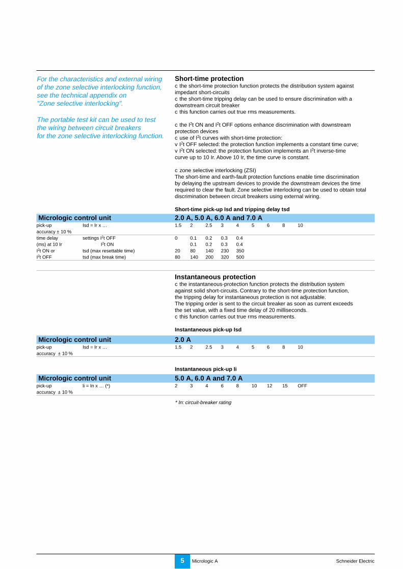
Short-time protectionc the short-time protection function protects the distribution system againstimpedant short-circuitsc the short-time tripping delay can be used to ensure discrimination with adownstream circuit breakerc this function carries out true rms measurements.
c the I2t ON and I2t OFF options enhance discrimination with downstreamprotection devicesc use of I2t curves with short-time protection:v I2t OFF selected: the protection function implements a constant time curve;v I2t ON selected: the protection function implements an I2t inverse-timecurve up to 10 Ir. Above 10 Ir, the time curve is constant.
c zone selective interlocking (ZSI)The short-time and earth-fault protection functions enable time discriminationby delaying the upstream devices to provide the downstream devices the timerequired to clear the fault. Zone selective interlocking can be used to obtain totaldiscrimination between circuit breakers using external wiring.
Short-time pick-up Isd and tripping delay tsd
Micrologic control unit 2.0 A, 5.0 A, 6.0 A and 7.0 Apick-up Isd = Ir x … 1.5 2 2.5 3 4 5 6 8 10accuracy ± 10 %time delay settings I2t OFF 0 0.1 0.2 0.3 0.4(ms) at 10 Ir I2t ON 0.1 0.2 0.3 0.4I2t ON or tsd (max resettable time) 20 80 140 230 350I2t OFF tsd (max break time) 80 140 200 320 500
Instantaneous protectionc the instantaneous-protection function protects the distribution systemagainst solid short-circuits. Contrary to the short-time protection function,the tripping delay for instantaneous protection is not adjustable.The tripping order is sent to the circuit breaker as soon as current exceedsthe set value, with a fixed time delay of 20 milliseconds.c this function carries out true rms measurements.
Instantaneous pick-up Isd
Micrologic control unit 2.0 Apick-up Isd = Ir x … 1.5 2 2.5 3 4 5 6 8 10accuracy ± 10 %
Instantaneous pick-up Ii
Micrologic control unit 5.0 A, 6.0 A and 7.0 Apick-up li = In x … (*) 2 3 4 6 8 10 12 15 OFFaccuracy ± 10 %
* In: circuit-breaker rating
For the characteristics and external wiringof the zone selective interlocking function,see the technical appendix on"Zone selective interlocking".
The portable test kit can be used to testthe wiring between circuit breakersfor the zone selective interlocking function.

Micrologic A Schneider Electric6
Discovering yourcontrol unit
Protection of the fourth pole on four-pole circuit breakersProtection of the neutral conductor depends on the distribution system.There are three possibilities.
Type of neutral Description.Neutral unprotected The distribution system does not require protection
of the neutral conductor.Neutral protection The cross-sectional area of the neutral conductorat 0.5 In is half that of the phase conductors.
c the long-time current setting Ir for the neutral is equalto half the setting valuec the short-time pick-up Isd for the neutral is equalto half the setting valuec the instantaneous pick-up Isd (Micrologic 2.0 A)for the neutral is equal to half the setting valuec the instantaneous pick-up Ii (Micrologic 5.0 A / 6.0 A /7.0 A) for the neutral is equal to the setting value.
Neutral protection The cross-sectional area of the neutral conductor is equalat In to that of the phase conductors.
c the long-time current setting Ir for the neutral is equalto the setting valuec the short-time pick-up Isd for the neutral is equal tothe setting valuec the instantaneous pick-ups Isd and Ii for the neutralare equal to the setting value.
Overview of functionsCurrent protection
Earth-fault protection on Micrologic 6.0 Ac an earth fault in the protection conductors can provoke local temperature riseat the site of the fault or in the conductors.The purpose of the earth-fault protection function is to eliminate this type of fault.c there are two types of earth-fault protection.
Type DescriptionResidual c the function determines the zero-phase sequence
current, i.e. the vectorial sum of the phase and neutralcurrentsc it detects faults downstream of the circuit breaker.
Source Ground Return c using a special external sensor, this functiondirectly measures the fault current returningto the transformer via the earth cablec it detects faults both upstream and downstreamof the circuit breakerc the maximum distance between the sensorand the circuit breaker is ten metres.
c earth-fault and neutral protection are independent and can therefore becombined.
Earth-fault pick-up Ig and tripping delay tgThe pick-up and tripping-delay values can be set independently and are identicalfor both the residual and "source ground return" earth-fault protection functions.
Micrologic control unit 6.0 Apick-up Ig = In x … (*) A B C D E F G H Iaccuracy In ≤ 400 A 0.3 0.3 0.4 0.5 0.6 0.7 0.8 0.9 1± 10 % 400 A < In ≤ 1200 A 0.2 0.3 0.4 0.5 0.6 0.7 0.8 0.9 1
In > 1200 A 500 A 640 A 720 A 800 A 880 A 960 A 1040 A 1120 A 1200 Atime delay settings I2t OFF 0 0.1 0.2 0.3 0.4(ms) at 10 In (*) I2t ON 0.1 0.2 0.3 0.4I2t ON or tg (max resettable time) 20 80 140 230 350I2t OFF tg (max break time) 80 140 200 320 500
* In: circuit-breaker rating

Micrologic A Schneider Electric7
Current protection and alarms
Earth-leakage protection on Micrologic 7.0 Ac the earth-leakage protection function primarily protects people against indirectcontact because an earth-leakage current can provoke an increase in the potentialof the exposed conductive parts. The earth-leakage pick-up value I∆n is displayeddirectly in amperes and the tripping delay follows a constant-time curvec an external rectangular sensor is required for this functionc this function is inoperative if the long-time rating plug is not installedc d protected against nuisance tripping.c k DC-component withstand class A up to 10 A.
Pick-up value I∆n and tripping delay ∆t
Micrologic control unit 7.0 Apick-up I∆n 0.5 1 2 3 5 7 10 20 30accuracy0 to - 20 %time delay settings(ms) ∆t (max resettable time) 60 140 230 350 800
∆t (max break time) 140 200 320 500 1000
Overload LED
E51
398A
This LED signals that the long-time current setting Ir has been overrun.
Fault indications
E51
399A
E51
400A
E51
401A
E51
402A
Signals tripping due to anoverrun of the long-timecurrent setting Ir.
Signals tripping dueto an overrun of theshort-time pick-up Isdor the instantaneouspick-up Isd / Ii.
Signals tripping due to anoverrun of the earth-faultpick-up Ig or the earth-leakage pick-up I∆n.
Signals tripping due tothe auto-protectionfunction of the controlunit.
delay
short timeI itsd
(s)
long timealarm
test
800
earth leakage
12
35 7
1020
30
∆t(ms)
60.5
140
230 350I∆n(A)
settingx Ir
22.5
34 5
68
10
Isd
1.5on I2t
.2
.3.4 .4
.1
.2.3
.10
x In
34
6 8 101215
off2
.512
48
121620
tr(s)
at 6 Ir24.4
.5
.6.7
.8.9
.95
.981
Ir
x In
instantaneous
40
%
%
100
Micrologic 7.0 A Micrologic 7.0 A
Micrologic 7.0 A Micrologic 7.0 A
The auto-protection function (excessivetemperature or short-circuit higher thancircuit-breaker capacity) opens the circuitbreaker and turns on the Ap LED.
Caution.If the circuit breaker remains closed andthe Ap LED remains on, contact theSchneider after-sales support department.
Caution.The battery maintains the fault indications.If there are no indications, check thebattery.

Micrologic A Schneider Electric8
Discovering yourcontrol unit
Overview of functionsAmmeter measurements
c all Micrologic control units measure the true rms value of currentsc the most heavily loaded phase is continuously displayed on the digital screenc using the navigation buttons, it is possible to display successively the I1, I2, I3,neutral IN, Ig, I∆N and stored-current (maximeter) valuesc the percent load on each phase is displayed. A bargraph displays the currentsmeasured on phases 1, 2 and 3 as a percentage of the long-time current setting Ir.
E60
371A
40
%
%
1001.125 x Ir1 x Ir0.8 x Ir0.6 x Ir0.4 x Ir
If no information is displayed on the screen,see the technical appendix "Digital display".

Micrologic A Schneider Electric9

Micrologic A Schneider Electric10
Setting your control unit Selecting the typeof neutral protection
On four-pole circuit breakers, it is possible to select the type of neutral protectionfor the fourth pole:c neutral unprotected (4P 3D);c neutral protection at 0.5 In (3D + N/2);c neutral protection at In (4P 4D).
E51
383A
4P 3D
3D+N/2
4P 4D
Micrologic A Schneider Electric11
Setting procedure
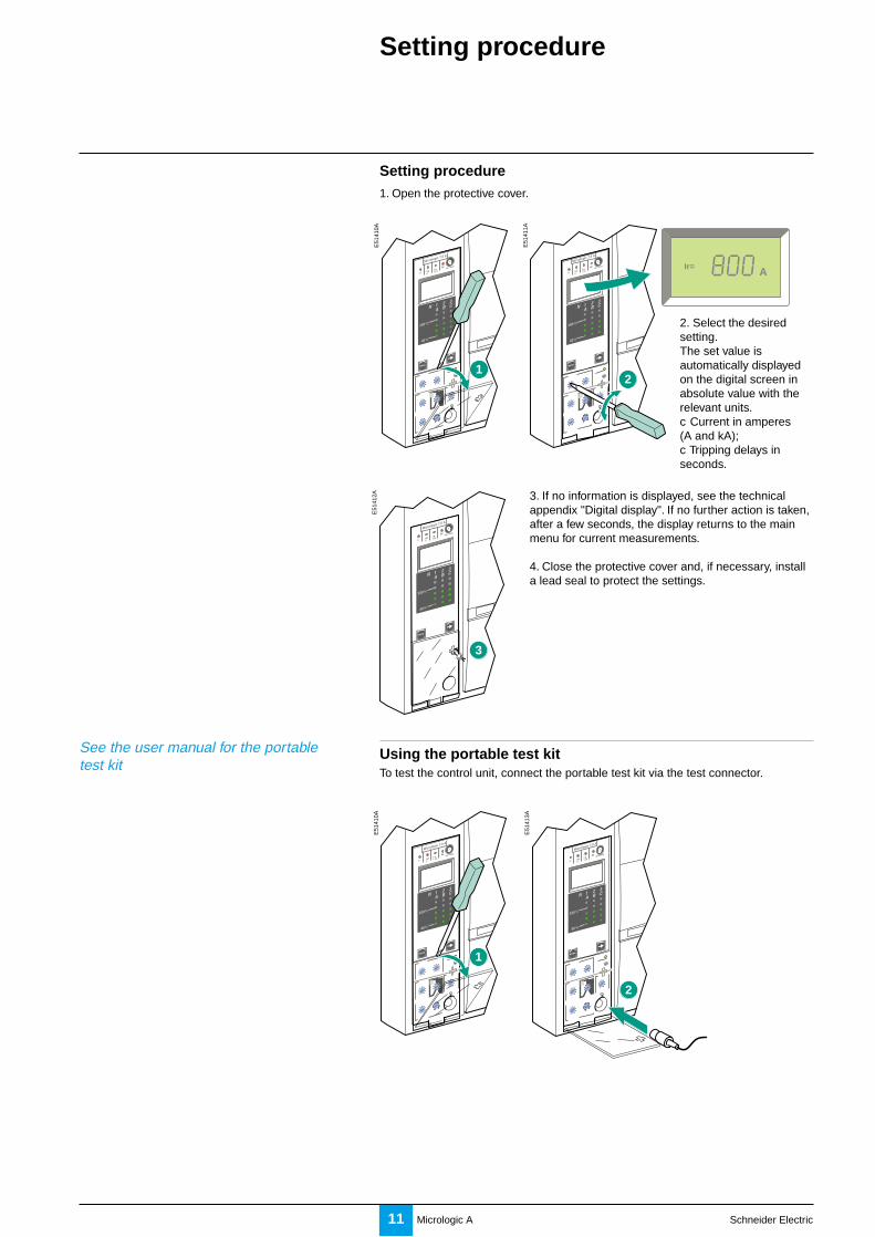
Setting procedure1. Open the protective cover.
2. Select the desiredsetting.The set value isautomatically displayedon the digital screen inabsolute value with therelevant units.c Current in amperes(A and kA);c Tripping delays inseconds.
E51
410A
E51
411A
3. If no information is displayed, see the technicalappendix "Digital display". If no further action is taken,after a few seconds, the display returns to the mainmenu for current measurements.
4. Close the protective cover and, if necessary, installa lead seal to protect the settings.
E51
412A
Using the portable test kitTo test the control unit, connect the portable test kit via the test connector.
1
Micrologic 7.0 A
40
100%
%
menu
Micrologic 7.0 A
40
100%
%
menu
2
AIr=
3
Micrologic 7.0 A
40
100%
%
menu
E51
413A
2
Micrologic 7.0 A
40
100%
%
menu
E51
410A
1
Micrologic 7.0 A
40
100%
%
menu
See the user manual for the portabletest kit

Micrologic A Schneider Electric12
Setting your control unit Setting the Micrologic 2.0 Acontrol unit
Set the threshold values
E51
366A E
6036
5A
Set the tripping delay
The rating of the circuit breakerin this example is 2000 A.
See pages 4 and 5 for informationon the available settings
E51
368A
E60
366A
E51
370A
1
In = 2000 A
In = 2000 A
In = 2000 A
Ir = 0.7 x In = 1400 A
Isd = 3 x Ir = 4200 A
alarm
x Ir
22.5
3 4 56
8101.5
setting
Isdinstantaneous
.4.5.6
.7.8
.9.95.98
1
long timeIr
x In
0 I
tIr
Isd
long timealarm
.512
48
121620
tr(s)
at 6 Ir24
tr = 1 second
0 I
t
tr

Micrologic A Schneider Electric13
Setting the Micrologic 5.0 Acontrol unit
Set the threshold values
E51
366A E
6036
7A
Set the tripping delay
The rating of the circuit breakerin this example is 2000 A.
See pages 4 and 5 for informationon the available settings
E60
368A
In = 2000 A
Ir = 0.7 x In = 1400 A
Ii = 3 x In = 6000 A
Isd = 2 x Ir = 2800 A.4
.5
.6.7
.8 .9.95.98
1
setting
short timeI i
x Ir
22.5
3 4 568
10
Isd
1.5
long timealarmIr
x In
x In
34
6 8 101215
off2
instantaneous
tr = 1 second
tsd = 0.2 seconds
short time
long timealarm
.512
4 8 1216
20
tr(s)
at 6 Ir24
delay
tsd(s)
on I2t
.2
.3.4 .4
.1
.2.3
.10
I2t on I2t off
E51
372A
E51
373A
Ir
Isd
Ii
0 I
tIr
Isd
Ii
0 I
t
I2t ON curve I2t OFF curve
1
In = 2000 A
In = 2000 A
Thresholds
E51
375A
E51
376A
tr
tsd
0 I
t
tr
tsd
0 I
t
I2t ON curve I2t OFF curve
Tripping delays

Micrologic A Schneider Electric14
Setting your control unit Setting the Micrologic 6.0 Acontrol unit
Set the threshold values
E51
366A E
5141
4A
The rating of the circuit breakerin this example is 2000 A.
See pages 4 to 6 for informationon the available settings.
E51
373A
E51
372A
Ir
Isd
Ii
0 I
tIr
Isd
Ii
0 I
t
I2t ON curve I2t OFF curve
Set the tripping delay
E60
372A
E51
376A
E51
375A
tr
tsd
0 I
t
tr
tsd
0 I
t
E51
416A
E51
415A
E51
419A
E51
418A
0 I
t
tg
0 I
t
tg
1
In = 2000 A
In = 2000 A
short time
long timealarm
ground fault
setting
.4.5.6
.7.8
.9.95.98
1
Ir
x In
x Ir
22.5
3 4 56
810
Isd
1.5
BC
D E FGH
I
Ig
A
I i
x In
34
6 8 101215
off2
In = 2000 A
Ir = 0.7 x In = 1400 A
Ii = 3 x In = 6000 A
Isd = 2 x Ir = 2800 A
B Ig = 640 A
instantaneous
test
0 I
t
Ig
0 I
t
Ig
short time
long timealarm
ground fault
.512
48
121620
tr(s)
at 6 Ir24
delay
tsd(s)
on I2t
.2
.3.4 .4
.2.3
.10
off
tg(s)
on I2t
.2.3
.4 .4
.1
.2.3
.10off
tr = 1 second
tsd = 0.2 seconds
tg = 0.2 seconds
I2t on I2t off.1
test
Thresholds
Tripping delays
I2t ON curve I2t OFF curve

Micrologic A Schneider Electric15
Setting the Micrologic 7.0 Acontrol unit
Set the threshold values
E51
366A
E51
420A
The rating of the circuit breakerin this example is 2000 A.
See pages 4 to 7 for informationon the available settings.
Set the tripping delay
E60
373A
1
In = 2000 A
In = 2000 A
.4.5.6
.7 .8 .9.95.98
1
short timeI i
long timealarmIr
x In
ground fault
setting
x Ir
22.5
3 4 568
10
Isd
1.5x In
3
46 8 10
12
15off2
instantaneous
In = 2000 A
Ir = 0.7 x In = 1400 A
Ii = 3 x In = 6000 A
Isd = 2 x Ir = 2800 A
I∆n = 1 A
1
23 5 7
10
2030.5
I∆n(A)
test
short time
long timealarm
ground fault
.51
24 8 12
1620
tr(s)
at 6 Ir24
delay
tsd(s)
on I2t
.2
.3.4 .4
.1
.2.3
.10
off
800
∆t(ms)
60
140
230 350
tr = 1 second
tsd = 0.2 seconds
∆t = 140 milliseconds
I2t on I2t offtest
I2t OFF curve
E51
373A
E51
372A
Ir
Isd
Ii
0 I
tIr
Isd
Ii
0 I
t
I2t ON curve I2t OFF curve
E51
376A
E51
375A
tr
tsd
0 I
t
tr
tsd
0 I
t
E51
421A
E51
423A
Thresholds
Tripping delays
I2t ON curve
0 I
t
I∆n
0 I
t
∆t

Micrologic A Schneider Electric16
Fault and statusindications
The procedure for closing the circuitbreaker following a fault trip is presentedin the circuit-breaker user manual.
Resetting the fault indicationsand checking battery status
If the battery needs to be changed, pleaseuse the one with Schneider cataloguenumber 33593 (characteristics given on thebattery compartment cover).
Resetting the fault indicationsc determine why the circuit breaker tripped.The fault indication is maintained until it is reset on the control unit.v press the fault-trip reset button.
E51
439A
v check the parameter settings of the control unit.
Checking the battery
E51
441A
Press the battery-test button (same as the fault-trip reset button) to displaythe battery status.
If no information is displayed, either:c no battery is installed in the control unit, or;c an auxiliary power supply is required.See the technical appendix "Digital display".
Changing the control-unit battery
1. Remove the batterycover.
2. Remove the battery.
E51
442A
E51
443A
3. Insert a new battery.Check the polarity.
4. Put the cover back inplace. Press the battery-test button to check thenew battery.
E51
444A
Micrologic 7.0 A
E51
440A Micrologic 7.0 A
Battery fully chargedBattery half chargedChange the battery
40
100%
%
+ E51
445A
40
100%
%

Micrologic A Schneider Electric17
Testing the earth-fault and earth-leakage functions
Charge and close the circuit breaker.
Using a screwdriver, press the test button for earth-fault and earth-leakageprotection. The circuit breaker should open.
E51
410A
1
Micrologic 7.0 A
40
100%
%
menu
E51
456A
Micrologic 7.0 A
40
100%
%
menu
2
If the circuit breaker does not open, contact the Schneider after-salessupport department.

Micrologic A Schneider Electric18
Accessing the menus
Symbols used:
Briefly press a key.
Press and hold a key.
E51
404A
E51
405A
It is possible at any time to stop consultinga current measurement, a maximumcurrent value recorded by the maximeter orthe setting values. After a few seconds, theMicrologic control unit automatically returnsto the main menu displaying the currentvalue of the most heavily loaded phase.
The protection settings can be displayeddirectly on the digital display.
Three menus may be accessed on Micrologic control units, providing the followinginformation:c phase current measurements I1, I2, I3, neutral IN, earth-fault current Ig on theMicrologic 6.0 A control unit and earth-leakage current I∆n on the Micrologic 7.0 Acontrol unit;c maximeter current values for phases I1, I2, I3, neutral IN, the maximum earth-fault current Ig on the Micrologic 6.0 A control unit and the maximum earth-leakagecurrent I∆n on the Micrologic 7.0 A control unit;c protection settings and tripping delays.
Press the "menu" buttonto access the maximumcurrent values measuredby the maximeter.
Press the "menu" buttonto access the protectionsettings and trippingdelays.
Press the "menu" buttonto return to the currentmeasurements.
E51
406A
E51
407A
E51
408A
4. The system returnsto the main"Measurements" menu.
E51
409A
40
100%
%
A
menu
40
100%
%
A
Max
menu
40
100%
%
AIr=
menu
40
100%
%
A
Menus
1. Measurements 2. Maximeter 3. Settings

Micrologic A Schneider Electric19
Current values may be read in the"Measurements" menu, which is also themain menu.
If no particular action is taken, the systemdisplays the current value of the mostheavily loaded phase.
E51
409A
Measuring phase currents
Display of current I1. Display of current I2.
E51
425A
E51
426A
Press the "arrow" buttonto go on to current I2.
Press the "arrow" buttonto go on to current I3.
Display of current I3.
Display of current Ig(Micrologic 6.0 A) orcurrent I∆n(Micrologic 7.0 A).
Press the "arrow" buttonto go on to current IN ifthe circuit breaker isconnected to the neutral.
E51
427A
E51
428A
Display of current IN.
The system returns tothe display of current I1.
E51
429A
E51
409A
40
100%
%
A40
100%
%
A
40
100%
%
A
40
100%
%
A
40
100%
%
A
40
100%
%
A
40
100%
%
A
Press the "arrow" buttonto return to current I1.
"Measurements" menuPhase 1 is the most heavily loaded.
Press the "arrow" buttonto go on to the earth-faultcurrent Ig or the earth-leakage current I∆n.

Micrologic A Schneider Electric20
Menus
Maximum current values may be read inthe "Maximeter" menu.
If no particular action is taken, the systemreturns to the main menu.
E51
407A
Displaying the maximumcurrent values
Display of themaximum I1 current.
Display of themaximum I2 current.
E51
430A
E51
431A
Press the "arrow" buttonto go on to the maximumI2 current.
Press the "arrow" buttonto go on to the maximumI3 current.
Display of themaximum I3 current.
Press the "arrow" buttonto go on to the maximumearth-fault current Ig(Micrologic 6.0 A) or themaximum earth-leakagecurrent I∆n(Micrologic 7.0 A)
Press the "arrow" buttonto go on to the maximumIN current if the circuitbreaker is connected tothe neutral.
E51
432A
E51
433A
Display of themaximum IN current.
The system returns tothe display of themaximum I1 current.
E51
434A
E51
435A
Press the "arrow" buttonto return to the maximumI1 current.
40
100%
%
A
MAX
40
100%
%
A
MAX
40
100%
%
A
MAX
40
100%
%
MAX
A
40
100%
%
A
MAX
40
100%
%
A
MAX
40
100%
%
A
Max
menu
Display of the maximumIg current or themaximum I∆n current.
"Maximeter" menu.

Micrologic A Schneider Electric21
Maximum current values can be resetusing the "Maximeter" menu.
If no particular action is taken, the systemreturns to the main menu.
E51
407A
Resetting the maximum currentvalues
Select the maximumcurrent value to bereset (e.g. I2 max.).
Reset.
E51
436A
E51
437A
Press the "arrow" buttonas many times asrequired to select I2 max.
Press and hold the"arrow" button down forthree to four seconds.The current value flashesduring the reset, thenchanges to the presentvalue (the newmaximum).
Select another valueto reset or return tothe main menu.
Press the "arrow" buttonas many times asrequired to select anothermaximum value to resetor return to the mainmenu.
E51
438A
40
100%
%
A
Max
menu
40
100%
%
A
MAX
40
100%
%
A
MAX
40
100%
%
A
MAX
"Maximeter" menu.

Micrologic A Schneider Electric22
Menus Viewing the settingsE
6037
4A
Long-time current setting Ir
Long-time tripping delay tr
Short-time pick-up Isd
Short-time tripping delay tsd
Instantaneous pick-up Isd
Instantaneous pick-up Ii
Earth-fault pick-up Ig
Earth-leakage pick-up I∆n
Earth-fault tripping delay tg
Earth-leakage tripping delay ∆t
Micrologic control unit
Select the "Settings"menu.The Ir value is the firstdisplayed.
Press the "arrow" buttonto go on to the tr value.
Press the "arrow" buttonto go on to theshort-time Isd value.
Press the "arrow" buttonto go on to the tsdvalue.
Press the "arrow" buttonto go on to theinstantaneous Isdvalue.
Or
Press the "arrow" buttonto go on to the Ig value.
Or
Press the "arrow" buttonto go on to the tg value.
Or
the ∆t value.
Press the "arrow" buttonto return to thebeginning of the menu.
the instantaneous Iivalue.
menu
A
str=
AIsd=
stsd=
AIg=
s
tg=
s∆t=
AIr=
Ii=
Ir=
Isd= A
A
I∆n=
A
the I∆n value.
5.0 A 6.0 A 7.0 A2.0 A

Micrologic A Schneider Electric23

Micrologic A Schneider Electric24
Technical appendix Tripping curves
Long-time and instantaneous protection (Micrologic 2.0 A)
E60
369A
.5 .7 1 2 3 4 5 7 10 20 30 50 70 100 200 300
I / Ir
10 0005 000
2 000
1 000
500
200
100
50
20
10
5
2
1
.5
.2
.1.05
.02
.01
.005
.002
.001
t(s)
tr = 0.5…24 s
Isd = 1.5…10 x Ir
Ir = 0.4…1 x In
Long-time, short-time and instantaneous protection(Micrologic 5.0 A, 6.0 A and 7.0 A)
E60
370A
0
0.40.3
0.20.1
t(s)
.5 .7 1 2 3 4 5 7 10 20 3 5 7 10 20 30
10 0005 000
2 000
1 000
500
200
100
50
20
10
5
2
1
.5
.2
.1.05
.02
.01
.005
.002
.001
x In
tr = 0.5…24 s
Isd = 1.5…10 x Ir
Ir = 0.4…1 x In
Ii = 2…15 x In . OFF (1)
I2t OFF
x Ir
0.40.3
0.20. 1
I2t ON
0

Micrologic A Schneider Electric25
Earth-fault protection (Micrologic 6.0 A)
E46
266A
Ig = A…J x In (1) 1200 A max.
t(s)
I / In
10 0005 000
2 000
1 000
500
200
100
50
20
10
5
2
1
.5
.2
.1.05
.02
.01
.005
.002
.001.05.07 .1 .2 .3 .4 .5 .7 1 2 3 5 7 10 200 300
I2t OFF
0.4
0.30.20.1
I2t ON
0.4
0.30.20.1
0 0

Micrologic A Schneider Electric26
Technical appendix
Caution.Following any modifications to the long-time rating plug, all control-unit protectionparameters must be checked.
Changing the long-timerating plug
Select the long-time rating plugA number of setting ranges for the long-time current setting are available onMicrologic A control units by changing the long-time rating plug.
The available rating plugs are listed below.
Part number Setting range for the Ir value33542 standard 0.4 to 1 x Ir33543 low setting 0.4 to 0.8 x Ir33544 high setting 0.8 to 1 x Ir33545 without long-time protection
Change the long-time rating plugProceed in the following manner.
2. Open the protectivecover of the control unit.
3. Completely removethe long-time rating plug screw.
E51
378A
E51
379A
4. Snap out the ratingplug.
5. Clip in the new rating plug.
E51
380A
E51
381A
6. Refit the screw for thelong-time rating plug.
7. Check and/or modify thecontrol-unit settings.
Caution.If no long-time rating plug is installed, thecontrol unit continues to operate under thefollowing downgraded conditions:c the long-time current setting Ir is 0.4;c the long-time tripping delay trcorresponds to the value indicated by theadjustment dial;c the earth-leakage protection function isdisabled.
Micrologic 7.0 A
40
100%
%
menu
Micrologic 7.0 A
40
100%
%
menu
Micrologic 7.0 A
40
100%
%
menu
.4.5.6
.7.8 .9
.95
.98
1
long time
alarm
Ir
x In
.512
48 12
16
20
tr(s)
@ 6 Ir24
Micrologic 7.0 A
40
100%
%
menu
.4.5.6
.7.8 .9
.95
.98
1
long time
alarm
Ir
x In
.512
48 12
16
20
tr(s)
@ 6 Ir24
1. Open the circuit breaker.

Micrologic A Schneider Electric27
Caution.If the protection function is not used oncircuit breakers equipped for ZSIprotection, a jumper must be installed toshort terminals Z3, Z4 and Z5.If the jumper is not installed, the short-timeand earth-fault tripping delays are setto zero, whatever the position of theadjustment dial.
Zone selective interlocking (ZSI)
Operating principlec A fault occurs at point A.Downstream device no. 2 clears the fault and sends a signal to upstream deviceno. 1, which maintains the short-time tripping delay tsd or the earth-fault trippingdelay tg to which it is set.c A fault occurs at point B.Upstream device no. 1 detects the fault. In the absence of a signal from adownstream device, the upstream device immediately trips without taking intoaccount its tripping-delay settings. If it is connected to a device even furtherupstream, it sends a signal to that device, which delays tripping according to its tsdor tg setting.
Note :On a circuit breaker likely to receive a ZSI signal, the tsd and tg tripping delays must notbe set to zero, as this would make discrimination impossible.
E51
397A
A
B1
2
Upstreamcircuit breaker
Z1 Z2 Z3 Z4 Z5
Terminal blockfor externalconnections
Downstreamcircuit breaker
Terminal blockfor externalconnections
and/or
and/or
Terminal blockfor externalconnections
Z1 Z2 Z3 Z4 Z5
Z1 Z2 Z3 Z4 Z5
E60
375A
Connections between control unitsA logic signal (0 or 5 volts) can be used for zone selective interlocking between theupstream and downstream circuit breakers.c Micrologic 5.0 A, 6.0 A, 7.0 A.c Micrologic 5.0 P, 6.0 P, 7.0 P.c Micrologic 5.0 H, 6.0 H, 7.0 H.
Wiringc maximum impedance: 2.7 Ω / 300 metresc capacity of connectors: 0.4 to 2.5 mm2
c maximum cross-sectional area of wires (including insulation): 3.5 mm2
c wires: single or multicorec maximum length: 3000 metresc limits to device interconnection:v the common ZSI - OUT - SOURCE (Z1) and the output ZSI - OUT (Z2)can be connected to a maximum of 10 inputs;v a maximum of 100 devices may be connected to an input ZSI IN CR (Z4) or GF(Z5)c connections are made from the output ZSI - OUT (Z2) on the downstream deviceto the input(s) ZSI - IN - ST (Z4) and/or GF (Z5) on the upstream device.
Terminals Z1 to Z5 correspond to theidentical indications on the circuit-breakerterminal blocks.

Micrologic A Schneider Electric28
Technical appendix Digital display
c display of measurements operates without an external power supply.The digital display goes off if the current drops below 0.2 x In (In = rated current).c display back-lighting is disabled in the following situations:v current less than 1 x In on one phase;v current less than 0.4 x In on two phases;v current less than 0.2 x In on three phases.c the maximeter does not operate for currents under 0.2 x In.
These three functions may be maintained by adding an external power supply.Even if an external power supply is installed, the long-time, short-time,instantaneous and earth protection functions will not use it.
For information on connecting an externalpower supply, see the electrical diagramsin the circuit-breaker user manual.

Micrologic A Schneider Electric29
Thermal memory
Thermal memoryThe thermal memory is a means to simulate temperature rise and cooling causedby changes in the flow of current in the conductors.
These changes may be caused by:c repetitive motor starting;c loads fluctuating near the protection settings;c repeated circuit-breaker closing on a fault.
Control units without a thermal memory (contrary to bimetal strip thermalprotection) do not react to the above types of overloads because they do not lastlong enough to cause tripping. However, each overload produces a temperaturerise and the cumulative effect can lead to dangerous overheating.
Control units with a thermal memory record the temperature rise caused by eachoverload. Even very short overloads produce a temperature rise that is stored inthe memory.This information stored in the thermal memory reduces the tripping time.
Micrologic control units and thermal memoryAll Micrologic control units are equipped as standard with a thermal memoryc for all protection functions, prior to tripping, the temperature-rise and cooling timeconstants are equal and depend on the tripping delay in question:v if the tripping delay is short, the time constant is low;v if the tripping delay is long, the time constant is high.
c for long-time protection, following tripping, the cooling curve is simulated by thecontrol unit. Closing of the circuit breaker prior to the end of the time constant(approximately 15 minutes) reduces the tripping time indicated in the trippingcurves.

Schneider Electric Industries SA
Designed by: HeadLinesPrinted by:
As standards, specifications and designs develop from time, always ask for confirmation of theinformation given in this publication.
5, rue Nadar92506 Rueil-Malmaison CedexFranceTel: +33 (0)1 41 29 82 00Fax:+33 (0)1 47 51 80 20
http://www.schneiderelectric.com
04443724AA-A 11-99
This document has been printed on ecological paper.