micro motion 7827 digital viscosity meter - emerson electric · 2020-03-28 · micro motion 7827...
TRANSCRIPT

High performance industrial HFO viscosity meter
High performance viscosity sensor
High performance viscosity meter kits
7827
Product Data Sheet PS-001217, Rev. C April 2013
Micro Motion® 7827 Digital Viscosity Meter
Micro Motion® viscosity meters are built to tackle the most demanding process and control applications. Rugged and reliable direct insertion meters with very low maintenance, they provide fully integrated “fit and forget” viscosity measurement.
High accuracy viscosity and density measurement
• Multi-variable measurement of viscosity, density and temperature
• Unique direct insertion design in lengths up to 13 ft (4 m)
• Viscosity measurement up to 20,000 cP
Greatest installation flexibility
• Continuous, real-time measurement in pipelines, slipstreams andtanks
• Superior diagnostics and parameter calculations including referredviscosity and viscosity index
• Comprehensive communications and control capability
Superior reliability and safety
• Optimized design – insensitive to vibration, temperature, andpressure variations
7827 / 7829
7829Visconic
High performance marine and power HFO viscosity meter
7829Viscomaster

2 Micro Motion 7827 Digital Viscosity Meter
Micro Motion® 7827 Digital Viscosity MeterThe Micro Motion® 7827 digital viscosity meter is an accurate measurement instrument used for continuous real-time process control of liquid viscosity and density in pipeline, slipstream/bypass and tank installations.
About the 7827 Digital Viscosity Meter
The 7827 digital viscosity meter is used for measurement or control of on-line process viscosity. The meter is used in applications requiring continuous on-line viscosity measurement in pipelines and tanks. The 7827 meter is available as a long-stemmed version for top mounting in open or closed tanks.
The 7827 digital viscosity meter works with the Micro Motion Model 7950 or Model 7951 signal converter to directly measure on-line viscosity, density, and temperature — allowing a true measurement of dynamic and kinematic viscosity. Additionally, parameters such as referred viscosity, referred density, and viscosity index can also be determined using the signal converters’ built-in calculations. These calculations are based on API and ASTM D341 standards.
With its multiple digital and analog communication connections, PID control, and alarm contacts, the combination of the 7827 meter with the 7950/7951 signal converter allows you to manage complex process and control applications where on-line measurements need to be referenced to laboratory conditions.
Advantages
• Fully integrated “fit and forget” digital viscosity and density measurement for monitoring and control
• Continuous, fast response digital measurement for closed loop control
• Measurements of viscosity and density at line and reference conditions
• Operates at viscosities up to 20,000 cP
• No moving parts means virtually no maintenance
• Integral Class B PT100 temperature sensor
• Hazardous-area approved (ATEX and CSA)
• Long-stemmed version is suitable for use on open and closed tanks and available in stem lengths up to 13 ft (4 m)
• Insensitive to vibration
• Direct insertion meter suitable for high-line pressure
Contents
Typical applications . . . . . . . . . . . . . . . . . . . . . . . . 3
Typical industries . . . . . . . . . . . . . . . . . . . . . . . . . . 3
Principle of operation. . . . . . . . . . . . . . . . . . . . . . . 3
Features. . . . . . . . . . . . . . . . . . . . . . . . . . . . . . . . . 4
Performance . . . . . . . . . . . . . . . . . . . . . . . . . . . . . 5
Temperature specification . . . . . . . . . . . . . . . . . . . 5
Pressure ratings. . . . . . . . . . . . . . . . . . . . . . . . . . . 6
Hazardous area classifications . . . . . . . . . . . . . . . 6
General classifications . . . . . . . . . . . . . . . . . . . . . 6
Materials of construction . . . . . . . . . . . . . . . . . . . . 7
Weight . . . . . . . . . . . . . . . . . . . . . . . . . . . . . . . . . . 7
Electrical . . . . . . . . . . . . . . . . . . . . . . . . . . . . . . . . 7
Dimensions . . . . . . . . . . . . . . . . . . . . . . . . . . . . . . 8
Installation . . . . . . . . . . . . . . . . . . . . . . . . . . . . . . 11
Ordering Information . . . . . . . . . . . . . . . . . . . . . . 12

Micro Motion 7827 Digital Viscosity Meter 3
Typical applications
• Heavy fuel oil (HFO) heater control to burners and engines
• Lube oil viscosity control
• Interface detection in multi-product pipelines
• Mass flow, when used in conjunction with a volumetric flow meter
• Product mixing and blending
Typical industries
• Oil and petrochemical
• Refining
• Power
• Heavy Fuel Oil (HFO) blending and bunkering
Principle of operation
The 7827 digital viscosity meter uses a vibrating fork technology to measure density and viscosity. As the liquid density changes, it affects the vibrating mass of the meter. The change in vibrating mass then affects the resonant frequency. Viscosity is a function of the bandwidth, which is an indication of the damping associated with the liquid.
The following figure illustrates how the 7827 meter with a 7950/7951 signal converter uses the resonant frequencies at point A (the lower –3 db point) and at point B (the upper –3 db point) to digitally calculate the density, bandwidth and quality factor. These measurements then give digitally determined values of fluid density and viscosity.
Product 1
Product 2
Response amplitude
Frequency (Hz)
Product 1 – Low ViscosityProduct 2 – High Viscosity
Bandwidth = Point B – Point AResonant Frequency = (Point A + Point B) / 2Quality Factor = Resonant Frequency / Bandwidth

4 Micro Motion 7827 Digital Viscosity Meter
Features
The 7827 digital viscosity meter works with the Model 7950 or Model 7951 signal converter to measure line viscosity, density, and temperature; and, calculate referred viscosity and base density using ASTM and API tables. Additionally, parameters such as °API and specific gravity also can be determined using the signal converter’s built in calculations. Any of these parameters can be used to drive mA outputs from the signal converter. See “7950/7951 signal converter features”.
Installation and application flexibility
The 7827 meter can be easily installed in a slipstream/bypass, pipeline, open tank, pressurized vessel, or flow-through sample chamber. The availability of a choice of construction materials and connections allow this meter to be used in a wide range of applications.
Low maintenance required
Because the 7827 digital viscosity meter has no moving parts, minimal maintenance is required, leading to lower overall operating costs.
The vibrating forks are available with PFA coating to assist self-cleaning. PFA is ideal for hydrocarbon applications. Care should be taken if the PFA coating is to be used in a corrosive application. Please consult your local Micro Motion sales office.
Raw frequency output electronics
The 7827 digital viscosity meter is designed to operate with the Micro Motion Model 7950 and Model 7951 signal converters. See “7950/7951 signal converter features” below.
No field calibration required
The 7827 digital viscosity meter is factory-calibrated and no field calibration is required. The calibration is traceable to UK National Standards through the Micro Motion onsite accredited laboratory.
Auto-ranging measurement
Each factory calibration is designed to achieve maximum accuracy. The calibration measurements are: 0.5 to 10 cP, 10 to 100 cP, 100 to 1000 cP, and 1000 to 12,500 cP. An auto-ranging facility is provided for applications where the liquid viscosity extends over one or more of the current operating calibrated ranges.
Fluid characterization using viscosity
Because the 7827 meter is used with a 7950/7951 signal converter, complex measurements of liquid viscosity at conditions away from line temperature and pressure can be performed. Parameters such as viscosity at reference temperature and viscosity index are available.
7950/7951 signal converter features
Inputs from meter:
• Line viscosity (bandwidth)
• Line density (frequency)
• Temperature (PT100)
Typical 7950/7951 calculations:
• Referred kinematic viscosity
• Line dynamic/kinematic viscosity
• Referred density
• Specific gravity
• % concentration
7950/7951 outputs:
• Status
• Four 4–20 mA outputs (optional: 8)
• RS-232C/485

Micro Motion 7827 Digital Viscosity Meter 5
Performance
Temperature specification
Integral temperature sensor
Viscosity Calibrated Range 0.5 to 12,500 cP
Maximum Viscosity Operating Range 0.5 to 20,000 cP (using up to four calibrated ranges)
Viscosity Accuracy ±1% full scale of the operating calibrated range
Viscosity Repeatability ±0.5% of reading
Density Calibrated Range 0.65 to 1.25 g/cc 38 to 78 lb/ft3
Maximum Density Operating Range 0 to 3 g/cc 0 to 187.28 lb/ft3
Density Accuracy ±0.001 g/cc of reading ±0.0624 lb/ft3
Density Repeatability ±0.0001 g/cc ±0.0062 lb/ft3
Process Temperature Effect (Corrected) (1)
(1) Temperature effect is the maximum measurement offset due to process fluid temperature changing away from the factory calibration temperature.
0.0001 g/cc (per °C) 0.1 k/gm3 (per °C)
Process
Ambient
Short-stem versionLong-stem version
–40 °F to +185 °F (–40 °C to +85 °C)
–58 °F to +392 °F (–50 °C to +200 °C)–40 °F to +302 °F (–40 °C to +150 °C)
Technology 100 Ohms RTD (4 wire)
Accuracy PT100 BS1904 Class B, DIN 43760 Class B
6 Micro Motion 7827 Digital Viscosity Meter
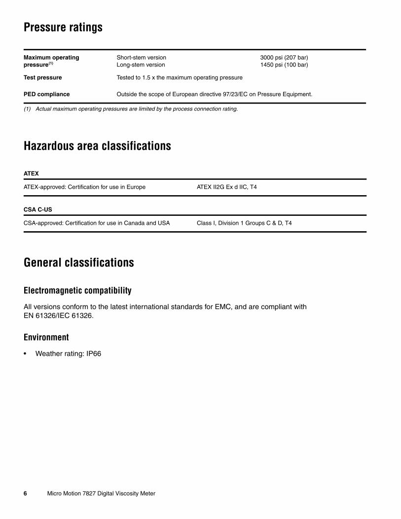
Pressure ratings
Hazardous area classifications
General classifications
Electromagnetic compatibility
All versions conform to the latest international standards for EMC, and are compliant with EN 61326/IEC 61326.
Environment
• Weather rating: IP66
Maximum operatingpressure(1)
(1) Actual maximum operating pressures are limited by the process connection rating.
Short-stem versionLong-stem version
3000 psi (207 bar)1450 psi (100 bar)
Test pressure Tested to 1.5 x the maximum operating pressure
PED compliance Outside the scope of European directive 97/23/EC on Pressure Equipment.
ATEX
ATEX-approved: Certification for use in Europe ATEX II2G Ex d IIC, T4
CSA C-US
CSA-approved: Certification for use in Canada and USA Class I, Division 1 Groups C & D, T4

Micro Motion 7827 Digital Viscosity Meter 7
Materials of construction
Weight
Electrical
Wetted parts Available in 316L Stainless steel, 304L Stainless steel, Alloy C22, Alloy B3, Alloy 400
Tine finish Standard, electro-polished, or PFA laminated(1) finishes available
(1) PFA is applied only to the tines for its anti-stick properties not for corrosion protection.
Electronics enclosure Short-stem version Sand cast low copper alloyPolyurethane paint finish
Long-stem version Sand cast low copper alloy, or stainless steelPolyurethane paint finish
Weight Short-stem versionLong-stem version
14.8 lb (6.7 kg) typicalDependent on stem length (contact factory)
Power supply requirement (from signal converter)
23 to 27 VDC, 50 mA
Outputs Viscosity and densityTemperature
Frequency100 Ohms RTD (4 wire)
Electrical connection Screw terminal, cable entry to suit ½” NPT gland (20 mm adaptor available)

8 Micro Motion 7827 Digital Viscosity Meter
Dimensions
7827 Short Stem
Cone-seat connection details
Flange connection details
Dimensions in inches (mm)
4.9 (125.4)5.5 (140)
→4.3 (109)
Mounting to suit 1.5″ Swagelok or similar cone
1.2(31)
1/2• NPT both sides
4.8
(121
)
0.5
(12) →
1.38
(35
)
Dimensions in inches (mm)
4.9 (125.4)5.5 (140)
→4.3 (109)
1.2(31)
1/2• NPT both sides
4.8
(121
)
0.5
(12) →
1.38
(35
)

Micro Motion 7827 Digital Viscosity Meter 9
7827 Long Stem
Open-tank connection (cast housing)
Open-tank connection (stainless steel housing)
→4.29 (109)
5.75 (146)
5.71 (145)
4.53
(11
5)
Pipe must be securely clamped in at least two
places along this length.
Electronic housing
External Earth connector
Lower nodal mass
Long stem 1.5• SCH 80 tube Vibrating element
Dimensions in inches (mm) Mounting hardware is customer specific, and is not supplied.
→1.
38 (
35)
19.68 (500)
Stem lengths up to 13 ft (4 m) are available as an ETO purchase.
→4.75 (120)
6.89 (175)
5.71 (145)
5.04
(12
8)
Pipe must be securely clamped in at least two
places along this length.
Amplifier housing
External Earth screw
Lower nodal mass
Long stem 1.5• SCH 80 tube Vibrating element
Dimensions in inches (mm) Mounting hardware is customer specific, and is not supplied.
Upper nodal mass
Cover lock screw M4 x 5 ST.STL - Kept captive by
data label
NP
T
→1.
38 (
35)
19.68 (500)
Stem lengths up to 13 ft (4 m) are available as an ETO purchase.

10 Micro Motion 7827 Digital Viscosity Meter
7827 Long Stem continued
Closed-tank connection (cast housing)
Closed-tank connection (stainless steel housing)
→4.29 (109)
11.4 (290)
4.53
(11
5)
Connection to pipeline (Zone 0 area) by means of a standardized industry flange (for example, DIN, ANSI, BS, or JIS Limit ANSI 1500 equivalent)
Electronic housing
External Earth connector
Lower nodal mass
Long stem 1.5• SCH 80 tube Vibrating element
Dimensions in inches (mm)
5.5 (140)
5.7 (145)
NP
T
→1.
38 (
35)
19.68 (500)
Stem lengths up to 13 ft (4 m) are available as an ETO purchase.
Connection to pipeline (Zone 0 area) by means of a standardized industry flange (for example, DIN, ANSI, BS, or JIS Limit ANSI 1500 equivalent)
5.71 (145)
5.5 (140)
Amplifier housing
External Earth screw
Lower nodal mass
Long stem 1.5• SCH 80 tube Vibrating element
→4.7 (120)
Upper nodal mass
Cover lock screw M4 x 5 ST.STL - Kept captive by
data label
Dimensions in inches (mm)
5 (1
28)
11.4 (290)
NP
T
→1.
38 (
35)
19.68 (500)
Stem lengths up to 13 ft (4 m) are available as an ETO purchase.

Micro Motion 7827 Digital Viscosity Meter 11
Installation
7827 Short Stem
A variety of installation accessories, can be provided, such as weldolets, for direct pipeline insertion or flow-through chambers, which provide the optimum environment for the short-stemmed 7827 meters.
7827 Long Stem
Open-tank installation example
Closed-tank installation example
For open-tank installations, the long-stemmed 7827 is clamped to a structure.
The position of the clamp determines the insertion depth.
For closed-tank installations, the long-stemmed 7827 needs a factory fitted flange attachment.
To vary the insertion depth, a standoff section with flange (not supplied) can then be used.

12 Micro Motion 7827 Digital Viscosity Meter
Ordering Information
Model Product description
7827 Digital viscosity meter, frequency output (for use with signal converters / flow computers 7950 / 7951 or similar)
Code Material of wetted parts
Available with all stem length codes:
A 316L Stainless steel, standard finish
C 316L Stainless steel, electro-polished finish
F 316L Stainless steel, PFA laminated tines
Z ETO material
Code Amplifier system
Available only with stem length codes A or Z:
A Frequency output ATEX II Ex d IIC T4 (< 200 °C)
B Frequency output CSA Class 1 Div 1 Groups C & D (< 200 °C)
Available for stem length codes C or Z:
G Frequency output – Safe area only (< 200 °C)
H Frequency output ATEX II Ex d IIC T4 (< 150 °C) [T4 (–40 °C < Ta < +110 °C)
J Frequency output CSA (C-US) Class 1 Div 1 Groups C & D (< 160 °C)
Code Amplifier enclosure
Available with all stem length codes:
A Aluminium alloy [T4 (< 40 °C < Ta < +110 °C)]
Available for stem length codes C or Z:
C Stainless steel
Code Process connections
Available with all stem length codes:
A 2" ANSI CL150 raised-face (RF) flange EN1092
B 2" ANSI CL300 raised-face (RF) flange EN1092
C 2" ANSI CL600 raised-face (RF) flange EN1092
G 50 mm DN50/PN40 DIN 2527
R 50 mm DN50/PN16 DIN 2527
Z ETO process connection
Available only with stem length codes A or Z:
N 1.5" Cone seat compression fitting
Code Stem length
A 0 mm: no stem extension and with standard spigot
C 500 mm / 20" (with removable transit cover)
Z ETO stem length(1)
(1) Stem lengths up to 13 ft (4 m) are available as an ETO purchase.
Continued on next page

Micro Motion 7827 Digital Viscosity Meter 13
Ordering Information continued
Code Default configuration
T No software configuration – frequency output only
Code Calibration range
B 0.5 to 100 cP
C 0.5 to 1000 cP
F 10 to 1000 cP
Z ETO calibration range
Available only with calibration type code A:
D 0.5 to 12500 cP
E 10 to 12500 cP
G 100 to 12500 cP
Code Calibration type
Available with all stem length codes:
A Free stream
Z ETO calibration type
Available only with stem length codes A or Z:
B(1)
(1) Available with calibration range B only.
2” schedule 40 boundary (200 cP limit)
D(1) 2” schedule 80 boundary (200 cP limit)
E 3" schedule 80 boundary
H(1) 2-1/2” schedule 40 boundary
Code Factory Set
B Reserved for future use
Code Traceability
A None
X Certificates of material traceability (per single order)
Typical model number: 7827AAAAATBABA

14 Micro Motion 7827 Digital Viscosity Meter

Micro Motion 7827 Digital Viscosity Meter 15

�������������� � ����������������������� ������������ ����������������������������������������������� ���!""#"��� $�%���&!"�!"��' $�%���&!���(!)*+��� � !"!!!��)!�����,����� � !(��(����������-�� � !!�!�"���!"�.�-��� � !�"#��)"��!�
�������������� � ������������������������������� ��
��/�������� � %��&���()!!!!��,��0 � $�"%�&"��#����
�121 � ����"(��)��3�����4�5� � $�()!)��)���
5���6 � ��������(7�0��6 � ������"!�(�'���� � ����)��)��8�9�� � $)��(�������������:;�����;���< � $(�(��#�#���
�������������� � �������������������� �����
���,�<�� � %#!&#����"��
AustraliaChinaIndiaJapanSouth Korea � %�"&"�(��(#��
� %��&�!�#)#���� %)�&""###"�!##� %�#&"�"�)")���� %#�&�)�"��"��
�<��� � $�()��!�#���
Micro Motion—The undisputed leader in flow and density measurement
WWW.micromotion.com
For a complete list of contact information and websites, please visit: www.emersonprocess.com/home/contacts/global.
World-leading Micro Motion measurement solutions from Emerson Process Management deliver what you need most:
Technology leadershipMicro Motion introduced the first reliable Coriolis meter in 1977. Since that time, our ongoing product development has enabled us to provide the highest performing measurement devices available.
Product breadthFrom compact, drainable process control to high flow rate fiscal transfer—look no further than Micro Motion for the widest range of measurement solutions.
Unparalleled valueBenefit from expert phone, field, and application service and support made possible by more than 750,000 meters installed worldwide and over 30 years of flow and density measurement experience.
© 2013 Micro Motion, Inc. All rights reserved.
The Micro Motion and Emerson logos are trademarks and service marks of Emerson Electric Co. Micro Motion, ELITE, MVD, ProLink, MVD Direct Connect, and PlantWeb are marks of one of the Emerson Process Management family of companies. All other trademarks are property of their respective owners.
Micro Motion supplies this publication for informational purposes only. While every effort has been made to ensure accuracy, this publication is not intended to make performance claims or process recommendations. Micro Motion does not warrant, guarantee, or assume any legal liability for the accuracy, completeness, timeliness, reliability, or usefulness of any information, product, or process described herein. We reserve the right to modify or improve the designs or specifications of our products at any time without notice. For actual product information and recommendations, please contact your local Micro Motion representative.