7827 digital viscosity meter · the 7827 meter is ideally suited to applications where continuous...
TRANSCRIPT

Installation and Configuration ManualP/N MMI-20015440, Rev. AAJuly 2009
Micro Motion® 7827 Digital Viscosity Meter
Short and Long Stem Versions

©2009, Micro Motion, Inc. All rights reserved. Micro Motion is a registered trade name of Micro Motion, Inc., Boulder, Colorado. The Micro Motion and Emerson logos are trademarks and service marks of Emerson Electric Co. All other trademarks are property of their respective owners.
Micro Motion pursues a policy of continuous development and product improvement. The specification in this document may therefore be changed without notice. To the best of our knowledge, the information contained in this document is accurate and Micro Motion cannot be held responsible for any errors, omissions, or other misinformation contained herein. No part of this document may be photocopied or reproduced without prior written consent of Micro Motion.
Installation and Configuration Manual i
Contents
Chapter 1 Introduction. . . . . . . . . . . . . . . . . . . . . . . . . . . . . . . . . . . . . . . . . 11.1 Safety guidelines . . . . . . . . . . . . . . . . . . . . . . . . . . . . . . . . . . . . . . . . . . . . . . . . . . . . . 11.2 About the meter. . . . . . . . . . . . . . . . . . . . . . . . . . . . . . . . . . . . . . . . . . . . . . . . . . . . . . 2
1.2.1 What is it? . . . . . . . . . . . . . . . . . . . . . . . . . . . . . . . . . . . . . . . . . . . . . . . . . 21.2.2 7827 meter measurements . . . . . . . . . . . . . . . . . . . . . . . . . . . . . . . . . . . . 21.2.3 What is it used for? . . . . . . . . . . . . . . . . . . . . . . . . . . . . . . . . . . . . . . . . . . 3
1.3 Principle of operation . . . . . . . . . . . . . . . . . . . . . . . . . . . . . . . . . . . . . . . . . . . . . . . . . 3
Chapter 2 Installation (Short Stem) . . . . . . . . . . . . . . . . . . . . . . . . . . . . . . . . 52.1 Introduction . . . . . . . . . . . . . . . . . . . . . . . . . . . . . . . . . . . . . . . . . . . . . . . . . . . . . . . . . 52.2 Boundary effects . . . . . . . . . . . . . . . . . . . . . . . . . . . . . . . . . . . . . . . . . . . . . . . . . . . . . 62.3 Standard installations . . . . . . . . . . . . . . . . . . . . . . . . . . . . . . . . . . . . . . . . . . . . . . . . . 8
2.3.1 Overview . . . . . . . . . . . . . . . . . . . . . . . . . . . . . . . . . . . . . . . . . . . . . . . . . . 82.3.2 Meter orientation . . . . . . . . . . . . . . . . . . . . . . . . . . . . . . . . . . . . . . . . . . . . 92.3.3 Free stream installation - flanged fitting . . . . . . . . . . . . . . . . . . . . . . . . . . 102.3.4 Free stream installation - weldolet . . . . . . . . . . . . . . . . . . . . . . . . . . . . . . 112.3.5 T-piece installation . . . . . . . . . . . . . . . . . . . . . . . . . . . . . . . . . . . . . . . . . . 122.3.6 Flow-through chamber installation . . . . . . . . . . . . . . . . . . . . . . . . . . . . . . 13
2.4 Installation in the pipeline or system . . . . . . . . . . . . . . . . . . . . . . . . . . . . . . . . . . . . . 142.5 Typical installations . . . . . . . . . . . . . . . . . . . . . . . . . . . . . . . . . . . . . . . . . . . . . . . . . . 17
2.5.1 Jacketed pipeline . . . . . . . . . . . . . . . . . . . . . . . . . . . . . . . . . . . . . . . . . . . 172.5.2 Flow-through chamber . . . . . . . . . . . . . . . . . . . . . . . . . . . . . . . . . . . . . . . 19
Chapter 3 Installation (Long Stem) . . . . . . . . . . . . . . . . . . . . . . . . . . . . . . . 213.1 Introduction . . . . . . . . . . . . . . . . . . . . . . . . . . . . . . . . . . . . . . . . . . . . . . . . . . . . . . . . 213.2 Installation considerations. . . . . . . . . . . . . . . . . . . . . . . . . . . . . . . . . . . . . . . . . . . . . 22
3.2.1 Fluid at the sensor . . . . . . . . . . . . . . . . . . . . . . . . . . . . . . . . . . . . . . . . . . 223.2.2 Flow rate . . . . . . . . . . . . . . . . . . . . . . . . . . . . . . . . . . . . . . . . . . . . . . . . . 223.2.3 Entrained gas. . . . . . . . . . . . . . . . . . . . . . . . . . . . . . . . . . . . . . . . . . . . . . 233.2.4 Solids contamination . . . . . . . . . . . . . . . . . . . . . . . . . . . . . . . . . . . . . . . . 23
3.3 Open-tank installation . . . . . . . . . . . . . . . . . . . . . . . . . . . . . . . . . . . . . . . . . . . . . . . . 233.4 Closed-tank installation . . . . . . . . . . . . . . . . . . . . . . . . . . . . . . . . . . . . . . . . . . . . . . . 263.5 Calibration . . . . . . . . . . . . . . . . . . . . . . . . . . . . . . . . . . . . . . . . . . . . . . . . . . . . . . . . . 293.6 If the Tank is Pressurized . . . . . . . . . . . . . . . . . . . . . . . . . . . . . . . . . . . . . . . . . . . . . 29
Chapter 4 Electrical Connections . . . . . . . . . . . . . . . . . . . . . . . . . . . . . . . . 314.1 Introduction . . . . . . . . . . . . . . . . . . . . . . . . . . . . . . . . . . . . . . . . . . . . . . . . . . . . . . . . 314.2 EMC and cabling considerations. . . . . . . . . . . . . . . . . . . . . . . . . . . . . . . . . . . . . . . . 314.3 Installation and safety in hazardous areas . . . . . . . . . . . . . . . . . . . . . . . . . . . . . . . . 324.4 Installation in non-hazardous areas . . . . . . . . . . . . . . . . . . . . . . . . . . . . . . . . . . . . . 324.5 Wiring the meter . . . . . . . . . . . . . . . . . . . . . . . . . . . . . . . . . . . . . . . . . . . . . . . . . . . . 324.6 Connecting the 7827 to a 795x series computer. . . . . . . . . . . . . . . . . . . . . . . . . . . . 34
4.6.1 Overview . . . . . . . . . . . . . . . . . . . . . . . . . . . . . . . . . . . . . . . . . . . . . . . . . 344.6.2 Connection diagrams . . . . . . . . . . . . . . . . . . . . . . . . . . . . . . . . . . . . . . . . 35
ii Micro Motion 7827 Digital Viscosity Meter
Contents
4.7 Checking the installation . . . . . . . . . . . . . . . . . . . . . . . . . . . . . . . . . . . . . . . . . . . . . . 37
Chapter 5 Using 7950/7951 Processing Electronics . . . . . . . . . . . . . . . . . . . . 395.1 Using the 7950 / 7951 Processing Electronics . . . . . . . . . . . . . . . . . . . . . . . . . . . . . 39
Chapter 6 Calibration Check. . . . . . . . . . . . . . . . . . . . . . . . . . . . . . . . . . . . 416.1 Introduction . . . . . . . . . . . . . . . . . . . . . . . . . . . . . . . . . . . . . . . . . . . . . . . . . . . . . . . . 416.2 Factory calibration. . . . . . . . . . . . . . . . . . . . . . . . . . . . . . . . . . . . . . . . . . . . . . . . . . . 41
6.2.1 Viscosity . . . . . . . . . . . . . . . . . . . . . . . . . . . . . . . . . . . . . . . . . . . . . . . . . 416.2.2 Density. . . . . . . . . . . . . . . . . . . . . . . . . . . . . . . . . . . . . . . . . . . . . . . . . . . 426.2.3 Primary standards . . . . . . . . . . . . . . . . . . . . . . . . . . . . . . . . . . . . . . . . . . 426.2.4 Transfer standards . . . . . . . . . . . . . . . . . . . . . . . . . . . . . . . . . . . . . . . . . . 42
6.3 In-line calibration. . . . . . . . . . . . . . . . . . . . . . . . . . . . . . . . . . . . . . . . . . . . . . . . . . . . 436.3.1 Viscosity . . . . . . . . . . . . . . . . . . . . . . . . . . . . . . . . . . . . . . . . . . . . . . . . . 436.3.2 Density. . . . . . . . . . . . . . . . . . . . . . . . . . . . . . . . . . . . . . . . . . . . . . . . . . . 436.3.3 Requirements for VOS correction . . . . . . . . . . . . . . . . . . . . . . . . . . . . . . 44
6.4 Performance . . . . . . . . . . . . . . . . . . . . . . . . . . . . . . . . . . . . . . . . . . . . . . . . . . . . . . . 456.4.1 Viscosity . . . . . . . . . . . . . . . . . . . . . . . . . . . . . . . . . . . . . . . . . . . . . . . . . 456.4.2 Density. . . . . . . . . . . . . . . . . . . . . . . . . . . . . . . . . . . . . . . . . . . . . . . . . . . 46
6.5 Calibration certificate example . . . . . . . . . . . . . . . . . . . . . . . . . . . . . . . . . . . . . . . . . 46
Chapter 7 General Maintenance . . . . . . . . . . . . . . . . . . . . . . . . . . . . . . . . . 497.1 Introduction . . . . . . . . . . . . . . . . . . . . . . . . . . . . . . . . . . . . . . . . . . . . . . . . . . . . . . . . 497.2 General maintenance . . . . . . . . . . . . . . . . . . . . . . . . . . . . . . . . . . . . . . . . . . . . . . . . 497.3 Fault analysis . . . . . . . . . . . . . . . . . . . . . . . . . . . . . . . . . . . . . . . . . . . . . . . . . . . . . . 50
7.3.1 Checking the Signal Converter . . . . . . . . . . . . . . . . . . . . . . . . . . . . . . . . 507.3.2 Checking the power consumption . . . . . . . . . . . . . . . . . . . . . . . . . . . . . . 527.3.3 Checking the installation . . . . . . . . . . . . . . . . . . . . . . . . . . . . . . . . . . . . . 53
Appendix A Calculated Parameters . . . . . . . . . . . . . . . . . . . . . . . . . . . . . . . . 55A.1 Introduction . . . . . . . . . . . . . . . . . . . . . . . . . . . . . . . . . . . . . . . . . . . . . . . . . . . . . . . . 55A.2 Viscosity equations . . . . . . . . . . . . . . . . . . . . . . . . . . . . . . . . . . . . . . . . . . . . . . . . . . 55
A.2.1 Quality factor . . . . . . . . . . . . . . . . . . . . . . . . . . . . . . . . . . . . . . . . . . . . . . 55A.2.2 General viscosity equation. . . . . . . . . . . . . . . . . . . . . . . . . . . . . . . . . . . . 56
A.3 Density equations . . . . . . . . . . . . . . . . . . . . . . . . . . . . . . . . . . . . . . . . . . . . . . . . . . . 56A.3.1 General density equation. . . . . . . . . . . . . . . . . . . . . . . . . . . . . . . . . . . . . 56A.3.2 Temperature correction equation . . . . . . . . . . . . . . . . . . . . . . . . . . . . . . . 56A.3.3 Viscosity correction equation. . . . . . . . . . . . . . . . . . . . . . . . . . . . . . . . . . 56A.3.4 Pressure correction . . . . . . . . . . . . . . . . . . . . . . . . . . . . . . . . . . . . . . . . 57A.3.5 Velocity Of Sound correction equation. . . . . . . . . . . . . . . . . . . . . . . . . . . 57A.3.6 Density scaling . . . . . . . . . . . . . . . . . . . . . . . . . . . . . . . . . . . . . . . . . . . . 58
A.4 Kinematic viscosity equation. . . . . . . . . . . . . . . . . . . . . . . . . . . . . . . . . . . . . . . . . . . 58
Appendix B Safety Certification. . . . . . . . . . . . . . . . . . . . . . . . . . . . . . . . . . . 59B.1 Safety certification. . . . . . . . . . . . . . . . . . . . . . . . . . . . . . . . . . . . . . . . . . . . . . . . . . . 59
Installation and Configuration Manual iii
Contents
Appendix C Product Data . . . . . . . . . . . . . . . . . . . . . . . . . . . . . . . . . . . . . . . 61C.1 Density / temperature relationship of hydrocarbon products. . . . . . . . . . . . . . . . . . . 61
C.1.1 Crude oil . . . . . . . . . . . . . . . . . . . . . . . . . . . . . . . . . . . . . . . . . . . . . . . . . 61C.1.2 Refined products . . . . . . . . . . . . . . . . . . . . . . . . . . . . . . . . . . . . . . . . . . . 61C.1.3 Platinum resistance law . . . . . . . . . . . . . . . . . . . . . . . . . . . . . . . . . . . . . 62C.1.4 Density of ambient air . . . . . . . . . . . . . . . . . . . . . . . . . . . . . . . . . . . . . . . 63C.1.5 Density of water . . . . . . . . . . . . . . . . . . . . . . . . . . . . . . . . . . . . . . . . . . . 63C.1.6 Velocity of sound in liquids. . . . . . . . . . . . . . . . . . . . . . . . . . . . . . . . . . . . 64
Appendix D Return Policy. . . . . . . . . . . . . . . . . . . . . . . . . . . . . . . . . . . . . . . 67D.1 General guidelines . . . . . . . . . . . . . . . . . . . . . . . . . . . . . . . . . . . . . . . . . . . . . . . . . . 67D.2 New and unused equipment . . . . . . . . . . . . . . . . . . . . . . . . . . . . . . . . . . . . . . . . . . . 67D.3 Used equipment . . . . . . . . . . . . . . . . . . . . . . . . . . . . . . . . . . . . . . . . . . . . . . . . . . . . 67

iv Micro Motion 7827 Digital Viscosity Meter
Contents
Installation and Configuration Manual 1
Installatio
n (S
ho
rt Stem
)E
lectrical Co
nn
ection
sIn
stallation
(Lo
ng
Stem
)In
trod
uctio
n
Chapter 1Introduction
1.1 Safety guidelinesHandle the 7827 digital viscosity meter with great care.
• Do not drop the meter.
• Do not use liquids incompatible with materials of construction.
• Do not operate the meter above its rated pressure or maximum temperature.
• Do not pressure test beyond the specified test pressure.
• Ensure all explosion-proof requirements have been applied.
• Ensure the meter and associated pipework are pressure tested to 1-1/2 times the maximum operating pressure after installation.
• Always store and transport the meter in its original packaging, including the transit cover secured by grub screws.
• To return a meter, refer to the Return Policy appendix for more information on the Micro Motion return policy.
Safety messages are provided throughout this manual to protect personnel and equipment. Read each safety message carefully before proceeding to the next step.
2 Micro Motion 7827 Digital Viscosity Meter
Introduction
1.2 About the meter
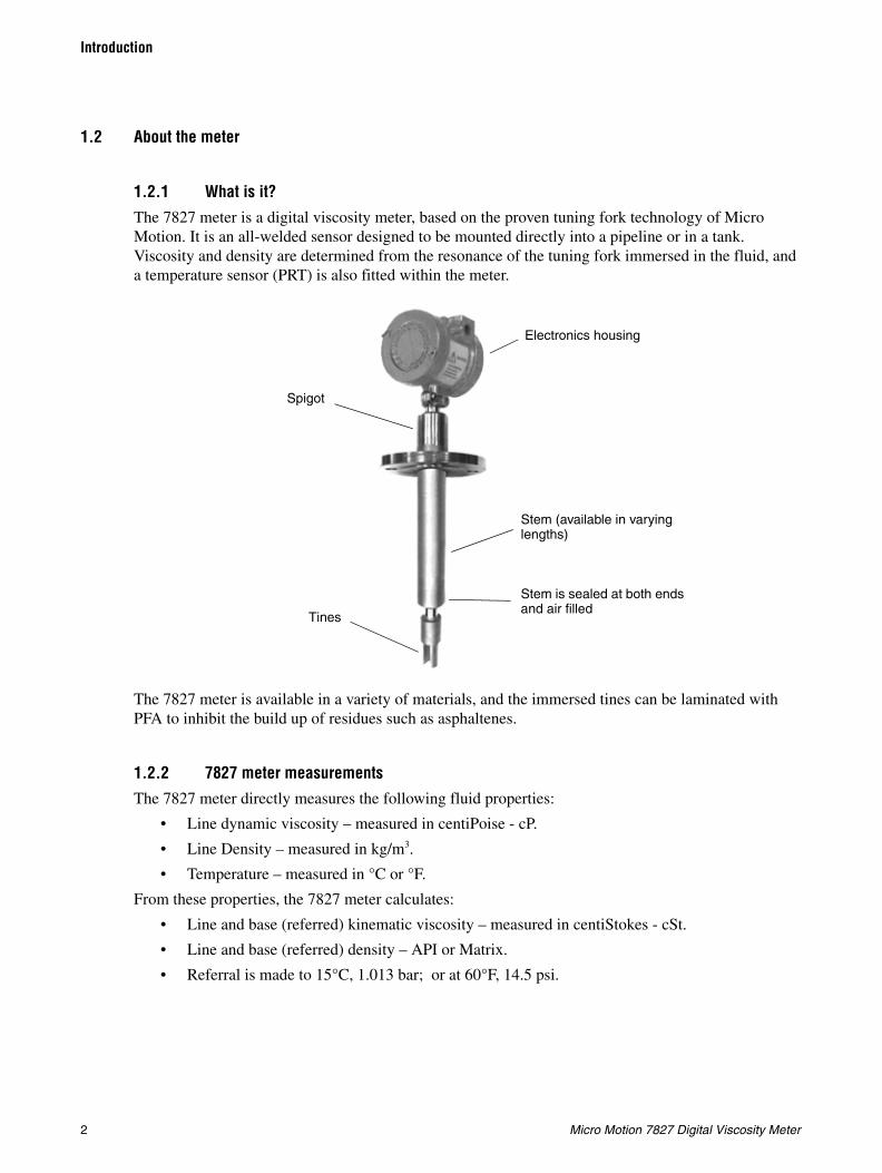
1.2.1 What is it?The 7827 meter is a digital viscosity meter, based on the proven tuning fork technology of Micro Motion. It is an all-welded sensor designed to be mounted directly into a pipeline or in a tank. Viscosity and density are determined from the resonance of the tuning fork immersed in the fluid, and a temperature sensor (PRT) is also fitted within the meter.
The 7827 meter is available in a variety of materials, and the immersed tines can be laminated with PFA to inhibit the build up of residues such as asphaltenes.
1.2.2 7827 meter measurementsThe 7827 meter directly measures the following fluid properties:
• Line dynamic viscosity – measured in centiPoise - cP.
• Line Density – measured in kg/m3.
• Temperature – measured in °C or °F.
From these properties, the 7827 meter calculates:
• Line and base (referred) kinematic viscosity – measured in centiStokes - cSt.
• Line and base (referred) density – API or Matrix.
• Referral is made to 15°C, 1.013 bar; or at 60°F, 14.5 psi.
Electronics housing
Spigot
Tines
Stem (available in varying lengths)
Stem is sealed at both ends and air filled
Installation and Configuration Manual 3
Introduction
Installatio
n (S
ho
rt Stem
)E
lectrical Co
nn
ection
sIn
stallation
(Lo
ng
Stem
)In
trod
uctio
n
1.2.3 What is it used for?
The 7827 meter is ideally suited to applications where continuous real time measurement of viscosity is required. The meter is particularly suited where viscosity is an indication of the behavioral properties of the fluid, for example in applications involving spraying, coating or dipping.
Some uses are in the oil and petrochemical industry for:
• Refining
• Marine
• Power
• Heavy fuel oil (HFO) blending and bunkering
1.3 Principle of operation
The 7827 meter operates on the vibrating element principle, the element in this case being a slender tuning fork structure which is immersed in the liquid being measured.
The tuning fork is excited into oscillation by a piezo-electric crystal internally secured at the root of one tine, while the frequency of oscillation is detected by a second piezo-electric crystal secured at the root of the other tine. The sensor is maintained at its first natural resonant frequency, as modified by the surrounding fluid, by an amplifier circuit located in the electronics housing.
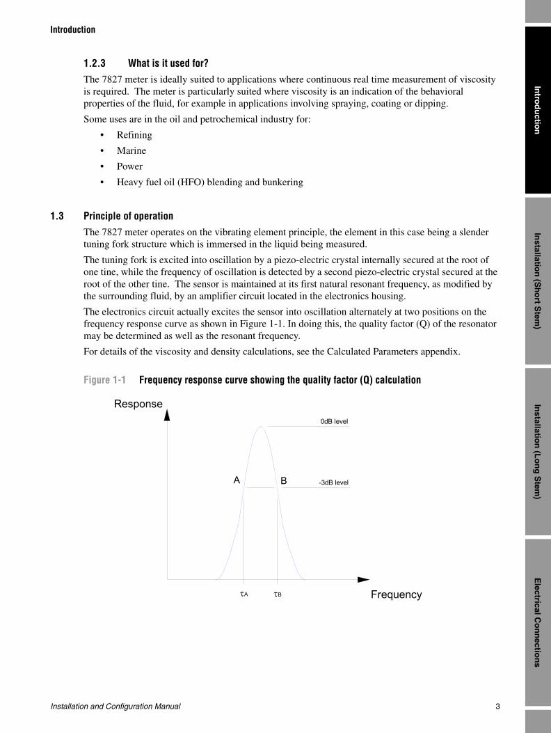
The electronics circuit actually excites the sensor into oscillation alternately at two positions on the frequency response curve as shown in Figure 1-1. In doing this, the quality factor (Q) of the resonator may be determined as well as the resonant frequency.
For details of the viscosity and density calculations, see the Calculated Parameters appendix.
Figure 1-1 Frequency response curve showing the quality factor (Q) calculation
0dB level
-3dB level
Frequency
Response
τBτA
A B

4 Micro Motion 7827 Digital Viscosity Meter
Introduction
Installation and Configuration Manual 5
Installatio
n (S
ho
rt Stem
)E
lectrical Co
nn
ection
sIn
stallation
(Lo
ng
Stem
)In
trod
uctio
n
Chapter 2Installation (Short Stem)
For information on installing a long-stem version of the 7827 digital viscosity meter, see Chapter 3.
2.1 Introduction
There are a variety of external factors that affect the ability of the 7827 digital viscosity meter to operate successfully. In order to ensure that your system works correctly, the effects of these factors must be taken into consideration when designing your installation.
There are two main aspects to consider:
• The accuracy and repeatability of the measurements
• The relevance of the measurements to the overall purpose of the system
Factors which may adversely affect accuracy and repeatability include:
• The presence of gas or bubbles within the fluid being measured
• Non-uniformity of the fluid
• The presence of solids as contaminants
• Fouling of the meter
• Temperature gradients
• Cavitations and swirls
• Operating at temperatures below the wax point of crude oils
• The correct pipe diameter that corresponds to the calibration of the meter.
In some applications, absolute accuracy is less important than repeatability. For example, in a system where the control parameters are initially adjusted for optimum performance, and thereafter only checked periodically.
The term achievable accuracy can be used to describe a measure of the product quality that can be realistically obtained from a process system. It is a function of measurement accuracy, stability and system response. High accuracy alone is no guarantee of good product quality if the response time of the system is measured in tens of minutes, or if the measurement bears little relevance to the operation of the system. Similarly, systems which require constant calibration and maintenance cannot achieve good achievable accuracy.
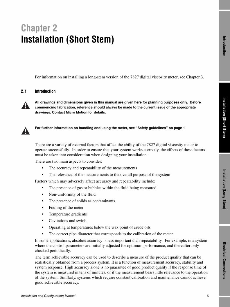
All drawings and dimensions given in this manual are given here for planning purposes only. Before commencing fabrication, reference should always be made to the current issue of the appropriate drawings. Contact Micro Motion for details.
For further information on handling and using the meter, see “Safety guidelines” on page 1

6 Micro Motion 7827 Digital Viscosity Meter
Installation (Short Stem)
Factors which may adversely affect the relevance of the measurements could include:
• Measurement used for control purposes being made too far away from the point of control, so that the system cannot respond properly to changes.
• Measurements made on fluid which is unrepresentative of the main flow.
2.2 Boundary effects
Any insertion device or meter can only measure the properties of the fluid within the region of fluid to which it is sensitive.
For practical reasons, it is helpful to consider the sensitive, or effective region, for the viscometer as an ovoid centered on the tips of the tines with its long axis aligned with the direction in which the tines vibrate, as shown below. The 7827 meter is insensitive to the properties of the fluid outside this region and progressively more sensitive to fluid properties the closer the fluid is to the tines. Density can be considered a “mass centered” effect and viscosity a “surface centered” effect in this visualization; i.e. the measurement of density is more uniformly sensitive to the density of fluid throughout the region while viscosity measurement is much more critically sensitive to fluid on the surface of the tines.
If part of this volume is taken up by the pipework or fittings there is said to be a boundary effect; i.e., the intrusion of the pipe walls will alter the calibration. The diagram below illustrates the 7827 meter installed in a pocket on the side of a 4" (100 mm) horizontal pipe line (viewed from above). The effective region is completely enclosed within the pipe line and thus is completely fluid.
long axis
shortaxis

Installation and Configuration Manual 7
Installation (Short Stem)
Installatio
n (S
ho
rt Stem
)E
lectrical Co
nn
ection
sIn
stallation
(Lo
ng
Stem
)In
trod
uctio
n
This next view shows other pipe outlines superimposed:
The smaller circle represents a 4" (100 mm) vertical pipe, which because the 7827 meter orientation is constant irrespective of pipe orientation intersects the effective region. The 6" (150 mm) pipe is the smallest pipe diameter to completely enclose the effective region when the pipe is vertical. Thus smaller pipe diameters can lead to a variety of different geometries which would each require a separate calibration.
An alternative condition is shown in the next diagram where the side pocket is extended until it passes completely through the effective region producing a “core”:
Top or Plan view
4” horizontal pipe2”Schedule 40Pocket or “T”
8 Micro Motion 7827 Digital Viscosity Meter
Installation (Short Stem)
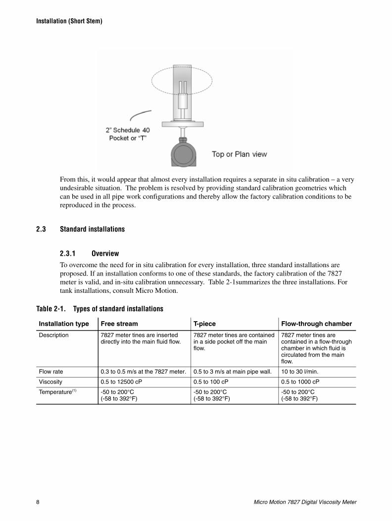
From this, it would appear that almost every installation requires a separate in situ calibration – a very undesirable situation. The problem is resolved by providing standard calibration geometries which can be used in all pipe work configurations and thereby allow the factory calibration conditions to be reproduced in the process.
2.3 Standard installations
2.3.1 OverviewTo overcome the need for in situ calibration for every installation, three standard installations are proposed. If an installation conforms to one of these standards, the factory calibration of the 7827 meter is valid, and in-situ calibration unnecessary. Table 2-1summarizes the three installations. For tank installations, consult Micro Motion.
Table 2-1. Types of standard installations
Installation type Free stream T-piece Flow-through chamber
Description 7827 meter tines are inserted directly into the main fluid flow.
7827 meter tines are contained in a side pocket off the main flow.
7827 meter tines are contained in a flow-through chamber in which fluid is circulated from the main flow.
Flow rate 0.3 to 0.5 m/s at the 7827 meter. 0.5 to 3 m/s at main pipe wall. 10 to 30 l/min.
Viscosity 0.5 to 12500 cP 0.5 to 100 cP 0.5 to 1000 cP
Temperature(1) -50 to 200°C(-58 to 392°F)
-50 to 200°C(-58 to 392°F)
-50 to 200°C(-58 to 392°F)

Installation and Configuration Manual 9
Installation (Short Stem)
Installatio
n (S
ho
rt Stem
)E
lectrical Co
nn
ection
sIn
stallation
(Lo
ng
Stem
)In
trod
uctio
n
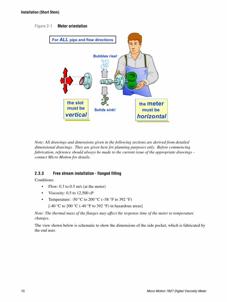
2.3.2 Meter orientationThe meter must always be installed horizontally, and orientated to allow flow in the gap between the tines. This is irrespective of the pipe line orientation, and helps to prevent the trapping of bubbles or solids on the meter.
Main flow pipe size 100 mm (4") horizontal 150 mm (6") vertical, or larger.
100 mm (4") horizontal or larger.
Any.
Advantages • Simple installation in large bore pipes.
• Ideal for clean fluids and non-waxing oils.
• Suitable for line viscosity measurement and simple referrals.
• Simple installation in large bore pipes.
• Ideal for clean fluids and non-waxing oils.
• Suitable for line viscosity measurement and simple referrals.
• Adaptable installation to any diameter main pipe and for tank applications.
• Ideal for flow and temperature conditioning.
• Suitable for complex referrals and for use with heat exchangers.
• Suitable for step changes in viscosity.
• Fast response.• Ideal for analyser
cubicles.
Not recommended for
• Dirty fluids.• Low or unstable flow rates.• Where step changes in viscosity can occur.
• For small bore pipes.
• Dirty fluids• Low or unstable flow rates.• Where step changes in
viscosity can occur.• for small bore pipes.• Where temperature effects
are significant.
• Uncontrolled flow rates.• Careful system design
required to ensure representative measurement.
• Frequently requires the use of a pump.
(1) Approval for use in hazardous areas is limited to –40 to +200°C (–40 to +392°F)
Table 2-1. Types of standard installations continued
Installation type Free stream T-piece Flow-through chamber
10 Micro Motion 7827 Digital Viscosity Meter
Installation (Short Stem)
Figure 2-1 Meter orientation
Note: All drawings and dimensions given in the following sections are derived from detailed dimensional drawings. They are given here for planning purposes only. Before commencing fabrication, reference should always be made to the current issue of the appropriate drawings - contact Micro Motion for details.
2.3.3 Free stream installation - flanged fittingConditions:
• Flow: 0.3 to 0.5 m/s (at the meter)
• Viscosity: 0.5 to 12,500 cP
• Temperature: -50 °C to 200 °C (–58 °F to 392 °F)
[-40 °C to 200 °C (-40 °F to 392 °F) in hazardous areas]
Note: The thermal mass of the flanges may affect the response time of the meter to temperature changes.
The view shown below is schematic to show the dimensions of the side pocket, which is fabricated by the end user.
Bubbles rise!
Solids sink!
the slot must be
vertical
.
For ALL pipe and flow directions.
the metermust be
horizontal

Installation and Configuration Manual 11
Installation (Short Stem)
Installatio
n (S
ho
rt Stem
)E
lectrical Co
nn
ection
sIn
stallation
(Lo
ng
Stem
)In
trod
uctio
n
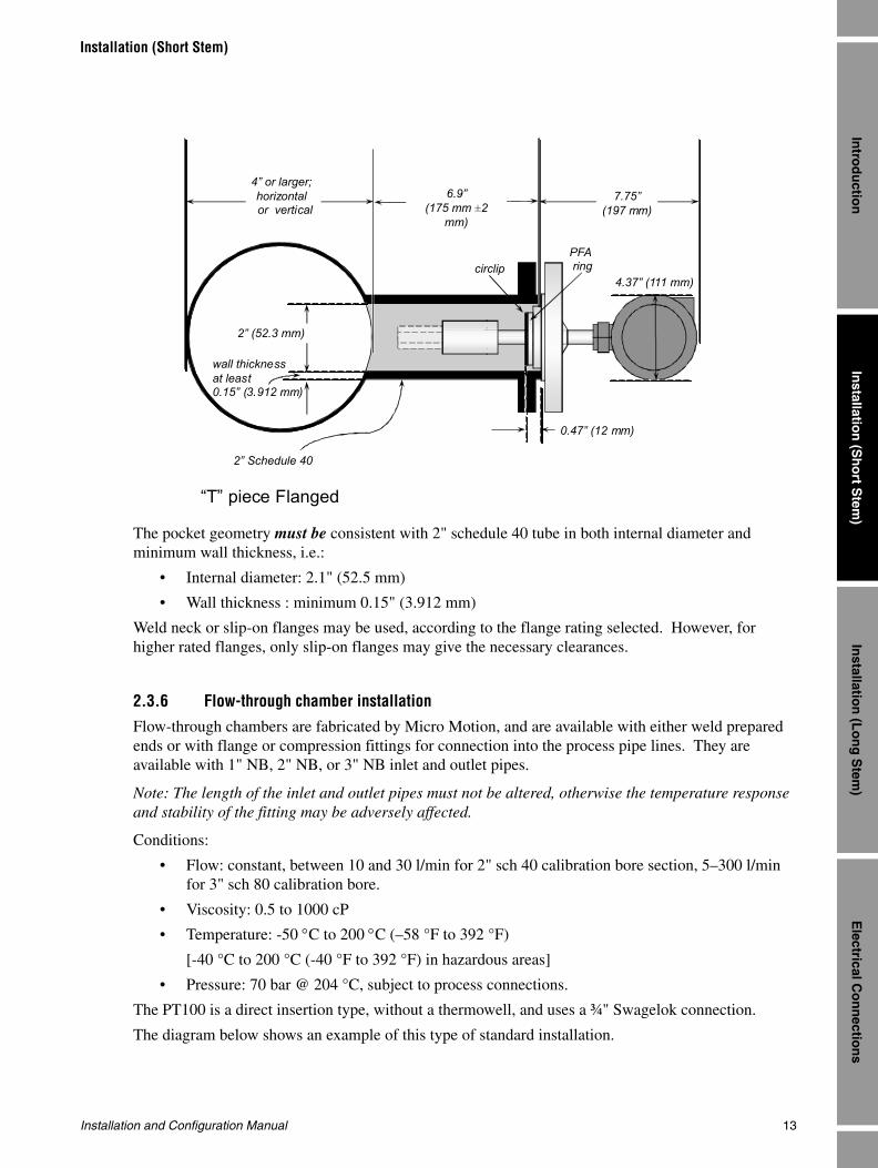
The pocket geometry must be consistent with 2" schedule 40 tube in both internal diameter and minimum wall thickness, such as:
• Internal diameter: 2" (52.5 mm)
• Wall thickness: minimum 0.15" (3.912 mm)
Weld neck or slip-on flanges may be used, according to the flange rating selected. However, for higher rated flanges, only slip-on flanges may give the necessary clearances.
2.3.4 Free stream installation - weldolet
This is the preferred option where temperature variations are a critical factor. The reduced thermal mass of the weldolet's taper-lock fitting renders it more able to track rapid changes in temperature.
Conditions:
• Flow: 0.3 to 0.5 m/s (at the meter)
• Viscosity: 0.5 to 12,500 cP
• Temperature: -50 °C to 200 °C (–58 °F to 392 °F)
[-40 °C to 200 °C (-40 °F to 392 °F) in hazardous areas]
The weldolet has a 1.5" taper lock fitting, and is supplied to be welded on 4", 6", 8" or 10" pipelines. Use of the weldolet ensures that the tines of the 7827 meter are orientated correctly and are fully inserted into the fluid stream.
Before fitting the weldolet, the pipeline must be bored through at 2.1" (52.5 mm) diameter to accept the viscometer. The weldolet must be welded to the pipeline concentrically with the pre-bored hole.
The view shown below is a schematic to show the relevant dimensions.
circlip
4” or larger; horizontal
6” or larger;vertical
2.75” (70 mm ±2 mm)
7.75”(197 mm)
Free Stream; flanged
2” (52.3 mm)
wall thicknessat least 0.15” (3.912 mm)
2” Schedule 40
4.37”(111 mm)
0.47” (12 mm)
PTFEring
circlip PTFEring
circlip PFAring
circlip
12 Micro Motion 7827 Digital Viscosity Meter
Installation (Short Stem)
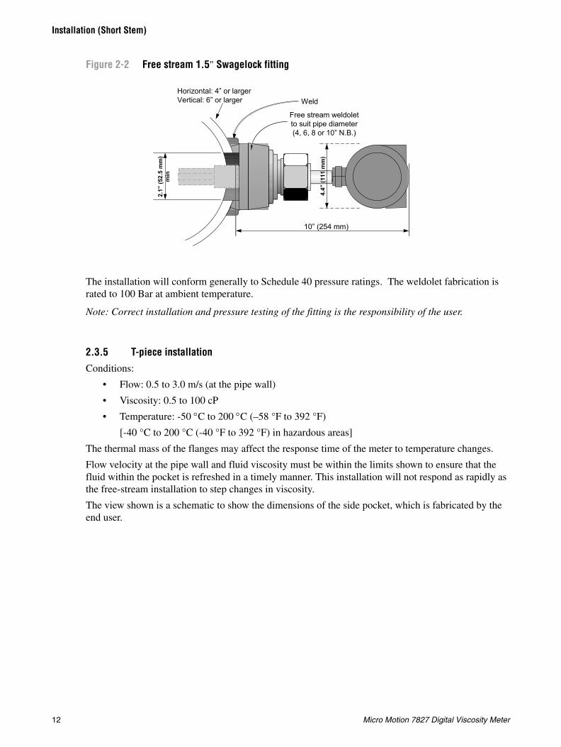
Figure 2-2 Free stream 1.5" Swagelock fitting
The installation will conform generally to Schedule 40 pressure ratings. The weldolet fabrication is rated to 100 Bar at ambient temperature.
Note: Correct installation and pressure testing of the fitting is the responsibility of the user.
2.3.5 T-piece installationConditions:
• Flow: 0.5 to 3.0 m/s (at the pipe wall)
• Viscosity: 0.5 to 100 cP
• Temperature: -50 °C to 200 °C (–58 °F to 392 °F)
[-40 °C to 200 °C (-40 °F to 392 °F) in hazardous areas]
The thermal mass of the flanges may affect the response time of the meter to temperature changes.
Flow velocity at the pipe wall and fluid viscosity must be within the limits shown to ensure that the fluid within the pocket is refreshed in a timely manner. This installation will not respond as rapidly as the free-stream installation to step changes in viscosity.
The view shown is a schematic to show the dimensions of the side pocket, which is fabricated by the end user.
10” (254 mm)
Horizontal: 4” or largerVertical: 6” or larger Weld
4.4”
(111
mm
)
Free stream weldoletto suit pipe diameter(4, 6, 8 or 10” N.B.)
2.1”
(52.
5 m
m)
min
Installation and Configuration Manual 13
Installation (Short Stem)
Installatio
n (S
ho
rt Stem
)E
lectrical Co
nn
ection
sIn
stallation
(Lo
ng
Stem
)In
trod
uctio
n
The pocket geometry must be consistent with 2" schedule 40 tube in both internal diameter and minimum wall thickness, i.e.:
• Internal diameter: 2.1" (52.5 mm)
• Wall thickness : minimum 0.15" (3.912 mm)
Weld neck or slip-on flanges may be used, according to the flange rating selected. However, for higher rated flanges, only slip-on flanges may give the necessary clearances.
2.3.6 Flow-through chamber installationFlow-through chambers are fabricated by Micro Motion, and are available with either weld prepared ends or with flange or compression fittings for connection into the process pipe lines. They are available with 1" NB, 2" NB, or 3" NB inlet and outlet pipes.
Note: The length of the inlet and outlet pipes must not be altered, otherwise the temperature response and stability of the fitting may be adversely affected.
Conditions:
• Flow: constant, between 10 and 30 l/min for 2" sch 40 calibration bore section, 5–300 l/min for 3" sch 80 calibration bore.
• Viscosity: 0.5 to 1000 cP
• Temperature: -50 °C to 200 °C (–58 °F to 392 °F)
[-40 °C to 200 °C (-40 °F to 392 °F) in hazardous areas]
• Pressure: 70 bar @ 204 °C, subject to process connections.
The PT100 is a direct insertion type, without a thermowell, and uses a ¾" Swagelok connection.
The diagram below shows an example of this type of standard installation.
“T” piece Flanged
D4” or larger; horizontal or vertical
6.9”(175 mm ±2
mm)
7.75”(197 mm)
2” (52.3 mm)
wall thicknessat least 0.15” (3.912 mm)
2” Schedule 40
PFAringcirclip
0.47” (12 mm)
4.37” (111 mm)

14 Micro Motion 7827 Digital Viscosity Meter
Installation (Short Stem)
The three compression fittings on the flow pockets (½" drain, ¾" temp probe, and 1-½" mounting nut for the meter) are rated to above the working pressure of the flow pocket. The fittings may be Swagelok or Parker; both are used in manufacture.
The fittings are certified to the following standards:
• Swagelok: SO9001 / 9002, ASME,TUV,CSA,DNV
• Parker: ISO 9001 / 9002, TUV, DNV, LLOYDS
2.4 Installation in the pipeline or system
Viscosity is a highly sensitive indicator of change in a fluid – a key reason why viscosity measurement is increasingly being chosen as a process measurement.
This sensitivity means that the measurement can be very sensitive to extraneous effects and therefore great care must be taken to consider all the factors which affect measurement when assessing the installation requirements.
Like many other meters, the optimum performance of the viscometer depends upon certain conditions of the fluid and configuration of the process pipe-work. By introducing appropriate flow conditioning, the optimum performance of the 7827 meter can be achieved at any chosen location in the process system.
Dimensions shown in inches (mm)

Installation and Configuration Manual 15
Installation (Short Stem)
Installatio
n (S
ho
rt Stem
)E
lectrical Co
nn
ection
sIn
stallation
(Lo
ng
Stem
)In
trod
uctio
n
You must first select a location which serves the application objective; e.g. installed close to the point of control. Then, consideration can be given to fluid conditioning at that point. Where the application requirements allow a degree of tolerance in the point chosen for installation, the installation may be able to take advantage of natural flow conditioning.
The choice of mechanical installation (free stream, “T” piece or flow-through chamber) will be dictated partly by application needs and partly by the fluid conditions, such as:
• Condition of fluid at the sensor
• Thermal effects
• Flow rate
• Entrained gas
• Solids contamination
Fluid at the sensor
The fluid in the effective zone of the 7827 meter must be of uniform composition and at uniform temperature. It must be representative of the fluid flow as a whole.
This is achieved either by mixing of the fluid either using a static inline mixer or taking advantage of any natural pipe condition that tends to cause mixing, such as pump discharge, partially open valves. The viscometer should be installed downstream where the flow is just returning to laminar flow conditions.
Thermal effectsAvoid temperature gradients in the fluid and in the pipe work and fittings immediately upstream and downstream of the viscometer.
Always insulate the viscometer and surrounding pipework thoroughly. Insulation must be at least 1" (25 mm) of rockwool, preferably 2" (50 mm) (or equivalent insulating heat jacket) and enclosed in a sealed protective casing to prevent moisture ingress, air circulation, and crushing of the insulation. Special insulation jackets are available from Micro Motion for the flow-through chambers, which, because of the low volumetric flow rates and hence low heat flow, are more vulnerable to temperature effects.
Avoid direct heating or cooling of the viscometer and associated pipe work upstream and downstream that is likely to create temperature gradients. If it is necessary to provide protection against cooling due to loss of flow, electrical trace heating may be applied, provided it is thermostatically controlled and the thermostat is set to operate below the minimum operating temperature of the system.
Where flow-through chambers are used and where base (or referred) viscosity is required and the behavior of the fluid is such that the temperature of the sample flow will require controlling, heat exchangers should be fitted upstream a sufficient distance from the chamber so that the fluid temperature is relatively stable. Insulation should be extended from the viscometer to the outlet from the heat exchanger. Fluid heat exchangers should be controlled by modulating the flow rate of the heat exchange fluid and not by modulating the sample flow rate.
Flow rate
Flow rates and velocities should be maintained relatively constant within the limits given. The fluid flow provides a steady heat flow into the viscometer section, and the flow rate influences the self cleaning of the sensor and the dissipation of bubbles and solid contaminants.
16 Micro Motion 7827 Digital Viscosity Meter
Installation (Short Stem)
Where it is necessary to install the viscometer in a by-pass (either using the free stream installation in a 4" diameter horizontal by-pass, or a flow-through chamber), flow may be maintained using pressure drop, pitot scoop, or by a sample pump. Where a pump is used, the pump should be upstream of the viscometer.
Entrained gas Gas pockets can disrupt the measurement. A brief disruption in the signal caused by transient gas pockets can be negated in the signal conditioning software, but more frequent disruptions or serious gas entrainment must be avoided. This can be achieved by observing the following conditions:
• Keep pipe lines fully flooded at all times
• Vent any gas prior to the viscometer
• Avoid sudden pressure drops or temperature changes which may cause dissolved gases to break out of the fluid
• Maintain a back pressure on the system sufficient to prevent gas break out (e.g. back pressure equivalent to twice the ‘head loss’ plus twice the vapor pressure)
• Maintain flow velocity at the sensor within the specified limits.
Solids contamination• Avoid sudden changes of velocity that may cause sedimentation.
• Install the viscometer far enough downstream from any pipework configuration which may cause centrifuging of solids (e.g. bends).
• Maintain flow velocity at the sensor within the specified limits.
• Use filtration if necessary.
The diagram below illustrates some of the principles outlined in this section. It shows a free-stream viscometer installation with an additional sample take off. The position of both is such that the static mixing (which could be caused by pump discharge or partially closed valve), has negated the adverse effects of bends and established laminar flow, and has ensured that the fluid is thoroughly mixed and thus of uniform composition and temperature. The ideal place for a free stream or “T” piece installation, or for the by-pass take off point is where the flow has just begun to be laminar.
Note: The insulation extends upstream and downstream far enough to prevent conduction losses in the pipe walls from degrading the temperature conditioning of the fluid at the sensor.

Installation and Configuration Manual 17
Installation (Short Stem)
Installatio
n (S
ho
rt Stem
)E
lectrical Co
nn
ection
sIn
stallation
(Lo
ng
Stem
)In
trod
uctio
n
2.5 Typical installationsThe following diagrams illustrate some typical solutions for line viscosity measurement, simple base viscosity referral and base viscosity using temperature control of the sample flow.
In all examples, the fluid flow is assumed to be uniform in composition and temperature as it enters the viscometer section.
2.5.1 Jacketed pipeline
The diagram below shows a jacketed pipeline. The heating fluid in the jacket will cause temperature gradients, and therefore it is discontinued through the viscometer section. If protection against cooling due to loss of flow is required through the unjacketed section then it must be provided using electrical trace heating.

18 Micro Motion 7827 Digital Viscosity Meter
Installation (Short Stem)
Figure 2-3 Jacketed pipeline installation
Alternatively, the viscometer can be installed in a by-pass. By ensuring that the sample is mixed where the by-pass draws off the main pipeline, it is not necessary to discontinue the main pipe line jacket. This is shown below.
Figure 2-4 4" bypass using DP to generate constant flow at the meter
Installation and Configuration Manual 19
Installation (Short Stem)
Installatio
n (S
ho
rt Stem
)E
lectrical Co
nn
ection
sIn
stallation
(Lo
ng
Stem
)In
trod
uctio
n
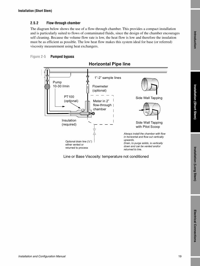
2.5.2 Flow-through chamber
The diagram below shows the use of a flow-through chamber. This provides a compact installation and is particularly suited to flows of contaminated fluids, since the design of the chamber encourages self cleaning. Because the volume flow rate is low, the heat flow is low and therefore the insulation must be as efficient as possible. The low heat flow makes this system ideal for base (or referred) viscosity measurement using heat exchangers.
Figure 2-5 Pumped bypass
PT100(optional)
Pump10-30 l/min
Insulation (required)
Optional drain line (½”) either vented or returned to process
Line or Base Viscosity: temperature not conditioned
Horizontal Pipe line
Flowmeter(optional)
1”-2” sample lines
Always install the chamber with flow in horizontal and flow out vertically upwards.Drain, to purge solids, is vertically down and can be vented and/or returned to line.
Side Wall Tapping
Side Wall Tapping with Pitot Scoop
Meter in 2”flow-through chamber

20 Micro Motion 7827 Digital Viscosity Meter
Installation (Short Stem)

Installation and Configuration Manual 21
Installatio
n (S
ho
rt Stem
)E
lectrical Co
nn
ection
sIn
stallation
(Lo
ng
Stem
)In
trod
uctio
n
Chapter 3Installation (Long Stem)
For information on installing a short-stem version of the 7827 digital viscosity meter, see Chapter 2.
3.1 Introduction
There are a variety of external factors that affect the ability of the 7827 digital viscosity meter to operate successfully. In order to ensure that your system works correctly, the effects of these factors must be taken into consideration when designing your installation.
There are two main aspects to consider:
• The accuracy and repeatability of the measurements
• The relevance of the measurements to the overall purpose of the system
Factors which may adversely affect accuracy and repeatability include:
• The presence of gas or bubbles within the fluid being measured
• Non-uniformity of the fluid
• The presence of solids as contaminants
• Fouling of the meter
• Temperature gradients
• Cavitations and swirls
• Operating at temperatures below the wax point of crude oils
In some applications, absolute accuracy is less important than repeatability. For example, in a system where the control parameters are initially adjusted for optimum performance, and thereafter only checked periodically.
All drawings and dimensions given in this manual are given here for planning purposes only. Before commencing fabrication, reference should always be made to the current issue of the appropriate drawings. Contact Micro Motion for details.
To protect the tines from damage, a Transit Cover is fitted prior to shipment from the factory. The Transit Cover is held in place by 2 grub screws. Be sure to remove and store the Transit Cover prior to installation. Re-fit the Transit Cover if storing or transporting, such as for repair. If the Transit Cover has been lost, it can be purchased from Micro Motion.
For further information on handling and using the meter, see “Safety guidelines” on page 1
22 Micro Motion 7827 Digital Viscosity Meter
Installation (Long Stem)
The term achievable accuracy can be used to describe a measure of the product quality that can be realistically obtained from a process system. It is a function of measurement accuracy, stability and system response. High accuracy alone is no guarantee of good product quality if the response time of the system is measured in tens of minutes, or if the measurement bears little relevance to the operation of the system. Similarly, systems which require constant calibration and maintenance cannot achieve good achievable accuracy.
Factors which may adversely affect the relevance of the measurements could include:
• Measurement used for control purposes being made too far away from the point of control, so that the system cannot respond properly to changes.
• Measurements made on fluid which is unrepresentative of the main flow.
3.2 Installation considerationsDensity and viscosity is a sensitive indicator of change in a fluid - a key reason why density and viscosity measurement is increasingly being chosen as a process measurement. However, density and viscosity measurements can be sensitive to extraneous effects and, therefore, great care must be taken to consider all the factors which may affect measurement when assessing the installation requirements.
Like many other meters, the optimum performance of the viscosity meter depends upon certain conditions of the fluid. You must first select a suitable position where the fork’s tines are always completely immersed in the fluid. Although tolerant of solids, turbulence and bubbles, there should be at least a 50 mm clearance from objects e.g. impellers, pipe stubs, etc.
Then consideration can be given to fluid conditioning at that point. Where the application requirements allow a degree of tolerance in the point chosen for installation, the installation may be able to take advantage of natural flow conditioning.
The choice of mechanical installation will be dictated partly by application needs and partly by the fluid conditions, such as:
• Condition of fluid at the sensor.
• Flow rate.
• Entrained gas.
• Solids contamination.
3.2.1 Fluid at the sensor
The fluid in the effective zone of the long stem 7827 meter must be of uniform composition and at uniform temperature. It must be representative of the fluid as a whole. This is achieved by taking advantage of any natural tank condition that tends to cause mixing, such as pump discharge, partially open valves etc.
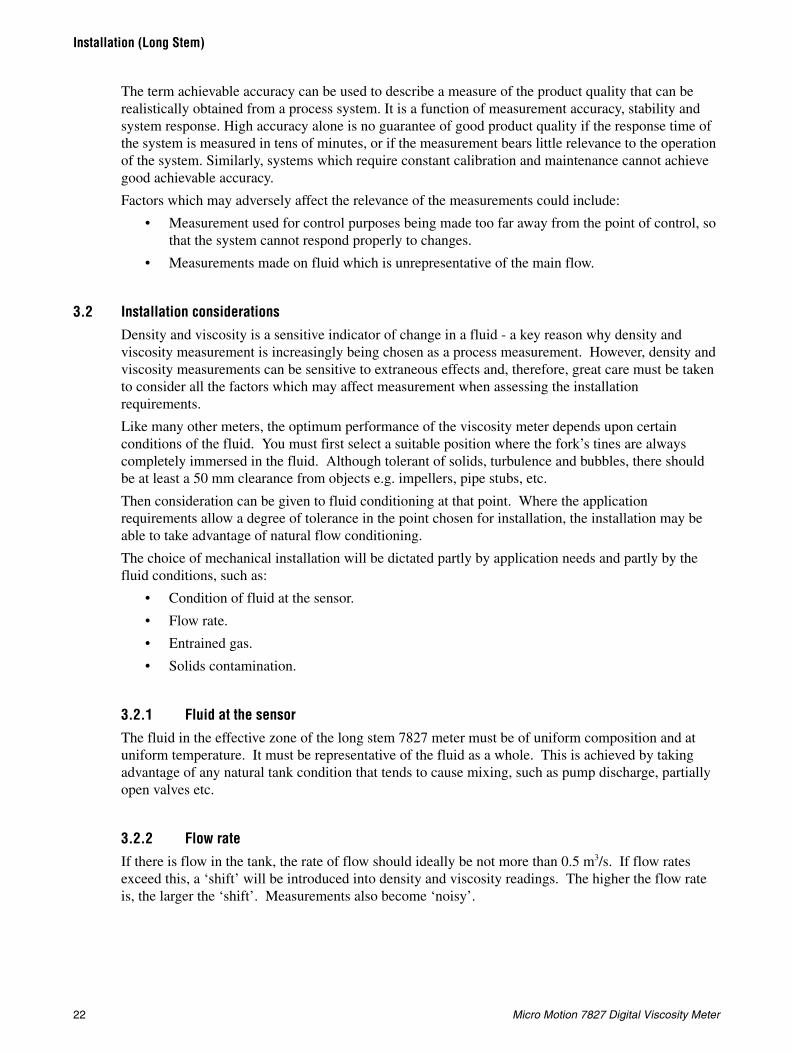
3.2.2 Flow rate
If there is flow in the tank, the rate of flow should ideally be not more than 0.5 m3/s. If flow rates exceed this, a ‘shift’ will be introduced into density and viscosity readings. The higher the flow rate is, the larger the ‘shift’. Measurements also become ‘noisy’.

Installation and Configuration Manual 23
Installation (Long Stem)
Installatio
n (S
ho
rt Stem
)E
lectrical Co
nn
ection
sIn
stallation
(Lo
ng
Stem
)In
trod
uctio
n
3.2.3 Entrained gas
Gas pockets can disrupt the measurement. A brief disruption in the signal caused by transient gas pockets can be negated in the internal signal conditioning software, but more frequent disruptions or serious gas entrainment must be avoided. This can be achieved by observing the following conditions:
• Vent any gas prior to the viscosity meter.
• Avoid sudden pressure drops or temperature changes which may cause dissolved gases to break out of the fluid.
3.2.4 Solids contamination• Avoid sudden changes of velocity that may cause sedimentation.
• Install the meter far enough away from any build-up of solids.
• Maintain flow velocity at the sensor within the specified limits.
• Specify the long-stem 7827 meter with a non-stick PFA protective layer.
3.3 Open-tank installation
1. For open-tank installations, the long-stemmed 7827 meter is clamped to a structure (see Figure 3-1). The position of the clamp determines the insertion depth.
Figure 3-1 Open-tank installation
2. Keep the tines away from the tank wall (see Figure 3-2).
Only the safe area model may be used in open-tank installation.
24 Micro Motion 7827 Digital Viscosity Meter
Installation (Long Stem)
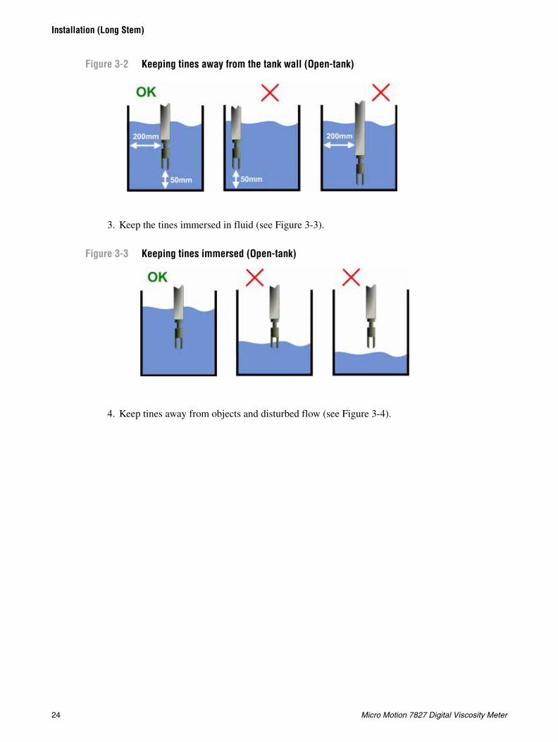
Figure 3-2 Keeping tines away from the tank wall (Open-tank)
3. Keep the tines immersed in fluid (see Figure 3-3).
Figure 3-3 Keeping tines immersed (Open-tank)
4. Keep tines away from objects and disturbed flow (see Figure 3-4).

Installation and Configuration Manual 25
Installation (Long Stem)
Installatio
n (S
ho
rt Stem
)E
lectrical Co
nn
ection
sIn
stallation
(Lo
ng
Stem
)In
trod
uctio
n
Figure 3-4 Keeping tines away from objects and disturbed flow (open tank)
5. If there is flow, align the tines such that the flow is directed towards the gap between the tines (see Figure 3-5).
Figure 3-5 Aligning the tines in flow (Open-tank)
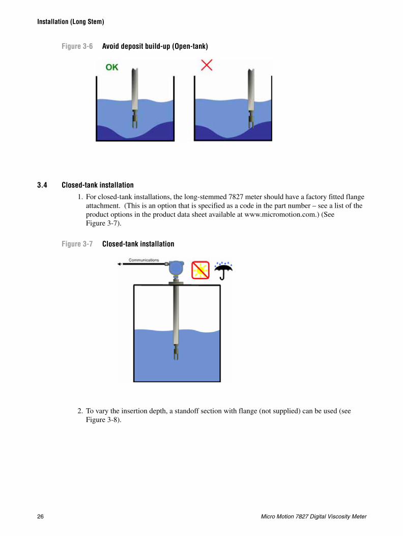
6. Keep away from deposit build-up (see Figure 3-6).
26 Micro Motion 7827 Digital Viscosity Meter
Installation (Long Stem)
Figure 3-6 Avoid deposit build-up (Open-tank)
3.4 Closed-tank installation1. For closed-tank installations, the long-stemmed 7827 meter should have a factory fitted flange
attachment. (This is an option that is specified as a code in the part number – see a list of the product options in the product data sheet available at www.micromotion.com.) (See Figure 3-7).
Figure 3-7 Closed-tank installation
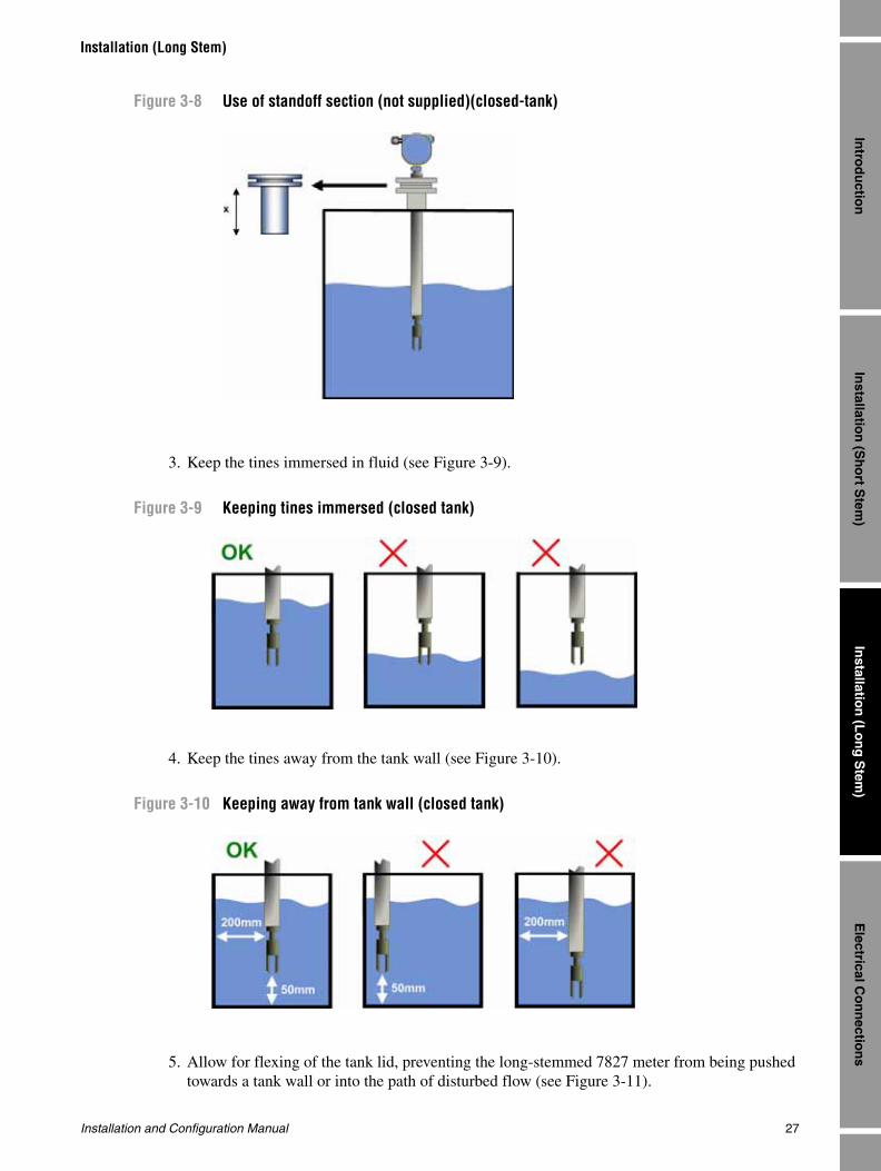
2. To vary the insertion depth, a standoff section with flange (not supplied) can be used (see Figure 3-8).
Installation and Configuration Manual 27
Installation (Long Stem)
Installatio
n (S
ho
rt Stem
)E
lectrical Co
nn
ection
sIn
stallation
(Lo
ng
Stem
)In
trod
uctio
n
Figure 3-8 Use of standoff section (not supplied)(closed-tank)
3. Keep the tines immersed in fluid (see Figure 3-9).
Figure 3-9 Keeping tines immersed (closed tank)
4. Keep the tines away from the tank wall (see Figure 3-10).
Figure 3-10 Keeping away from tank wall (closed tank)
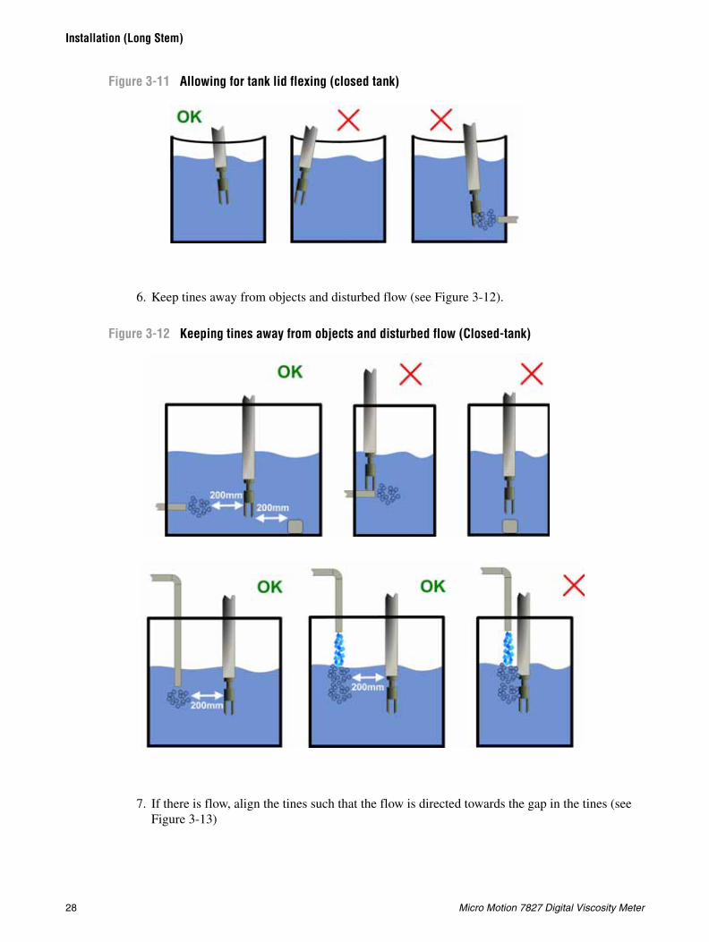
5. Allow for flexing of the tank lid, preventing the long-stemmed 7827 meter from being pushed towards a tank wall or into the path of disturbed flow (see Figure 3-11).
28 Micro Motion 7827 Digital Viscosity Meter
Installation (Long Stem)
Figure 3-11 Allowing for tank lid flexing (closed tank)
6. Keep tines away from objects and disturbed flow (see Figure 3-12).
Figure 3-12 Keeping tines away from objects and disturbed flow (Closed-tank)
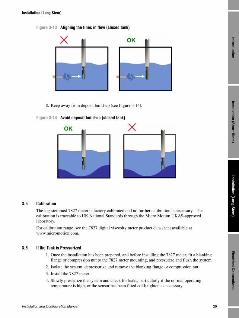
7. If there is flow, align the tines such that the flow is directed towards the gap in the tines (see Figure 3-13)
Installation and Configuration Manual 29
Installation (Long Stem)
Installatio
n (S
ho
rt Stem
)E
lectrical Co
nn
ection
sIn
stallation
(Lo
ng
Stem
)In
trod
uctio
n
Figure 3-13 Aligning the tines in flow (closed tank)
8. Keep away from deposit build-up (see Figure 3-14).
Figure 3-14 Avoid deposit build-up (closed tank)
3.5 CalibrationThe log-stemmed 7827 meter is factory calibrated and no further calibration is necessary. The calibration is traceable to UK National Standards through the Micro Motion UKAS-approved laboratory.
For calibration range, see the 7827 digital viscosity meter product data sheet available at www.micromotion.com.
3.6 If the Tank is Pressurized
1. Once the installation has been prepared, and before installing the 7827 meter, fit a blanking flange or compression nut to the 7827 meter mounting, and pressurize and flush the system.
2. Isolate the system, depressurize and remove the blanking flange or compression nut.
3. Install the 7827 meter.
4. Slowly pressurize the system and check for leaks, particularly if the normal operating temperature is high, or the sensor has been fitted cold; tighten as necessary.

30 Micro Motion 7827 Digital Viscosity Meter
Installation (Long Stem)
5. Once the system has stabilized and is leak free, fit the insulation material, remembering also to insulate any flanges.

Installation and Configuration Manual 31
Electrical Connections
Installatio
n (S
ho
rt Stem
)E
lectrical Co
nn
ection
sIn
stallation
(Lo
ng
Stem
)In
trod
uctio
nIn
stallation
(Sh
ort S
tem)
Electrical C
on
nectio
ns
Installatio
n (L
on
g S
tem)
Intro
du
ction
Installatio
n (S
ho
rt Stem
)E
lectrical Co
nn
ection
sIn
stallation
(Lo
ng
Stem
)In
trod
uctio
nIn
stallation
(Sh
ort S
tem)
Electrical C
on
nectio
ns
Installatio
n (L
on
g S
tem)
Intro
du
ction
Chapter 4Electrical Connections
4.1 IntroductionThis chapter shows you how to wire up the 7827 digital viscosity meter and then connect it to the Micro Motion® 795x series of computers.
Note: Only Micro Motion signal converters and flow computers are able to interpret the signals from the 7827 meter; it cannot be connected to equipment from other manufacturers.
4.2 EMC and cabling considerationsTo meet the EC Directive for EMC (Electromagnetic Compatibility) it is recommended that the meter be connected using a suitable instrumentation cable and earthed through the meter body and pipework. The instrumentation cable should have an individual screen, foil or braid over each twisted pair and an overall screen to cover all cores. Where permissible, the screen should be connected to earth at both ends. Note that for intrinsic safety, termination of the screen to earth in the hazardous area is not generally permitted.
To electrically connect the 7827 to a Micro Motion 795x series computer you will need the following:
• Minimum of 7-core screened twisted pairs with overall screen
• 795x connector plugs:
• 1/2" NPT to M20 x 1 Exd IIC-rated gland adaptor
• M20 x 1 Exd IIC-rated cable gland
• 1/2" NPT Exd IIC-rated blanking plug
• Hex drive, 2.5 mm AF (2.0 mm AF stainless steel enclosure)
• Electrical screwdriver, 3 mm drive
• Wire strippers
• Gland spanners / drives
For installations in hazardous areas:
• For ATEX installations, the electrical installation must strictly adhere to the safety information given in the ATEX safety instructions booklet shipped with this manual. See Section 1.1 for important information.
• For installations in USA and Canada, the electrical installation must strictly adhere to the Electrical Codes and a conduit seal is required within 2” (50 mm) of the enclosure.
7950 7951 Klippon 7951 D-type (Cannon)2 off 10-way 2 off 10-way 2 off 25-way1 off 4-way 1 off 4-way 1 off 4-way
32 Micro Motion 7827 Digital Viscosity Meter
Electrical Connections
4.3 Installation and safety in hazardous areas
The 7827 meter is explosive proof and can be installed in a hazardous area without the use of intrinsically safe barriers (or isolators). However, it is still necessary to observe the rules of compliance with current standards concerning flameproof equipment:
• The meter electronics housing covers must be tightened securely and locked into position by their locking screws.
• The electrical conduit must be fitted with an appropriate explosion-proof cable gland.
• If any electrical conduit entry port is not used it must be blanked off using the appropriate explosion-proof plug, with the plug entered to a depth of at least five threads.
• The spigot must be locked into place.
• The cabling used to wire the 7827 to the signal converter/flow computer must be of the appropriate Exd rating.
4.4 Installation in non-hazardous areas
Typically the 7827 meter will operate over cable lengths up to 2 km from a 24 V supply. Micro Motion recommend cables similar to BS 5308 or RS 368.
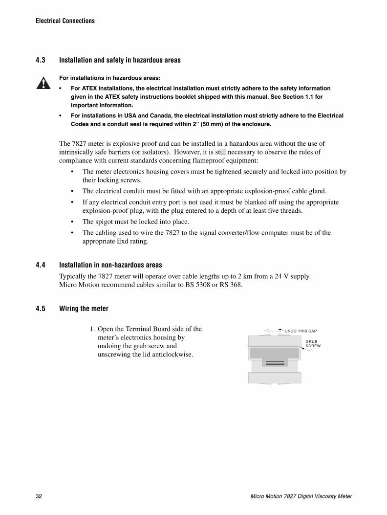
4.5 Wiring the meter
For installations in hazardous areas:
• For ATEX installations, the electrical installation must strictly adhere to the safety information given in the ATEX safety instructions booklet shipped with this manual. See Section 1.1 for important information.
• For installations in USA and Canada, the electrical installation must strictly adhere to the Electrical Codes and a conduit seal is required within 2” (50 mm) of the enclosure.
1. Open the Terminal Board side of the meter’s electronics housing by undoing the grub screw and unscrewing the lid anticlockwise.
GRUB SCREW
UNDO THIS CAP

Installation and Configuration Manual 33
Electrical Connections
Installatio
n (S
ho
rt Stem
)E
lectrical Co
nn
ection
sIn
stallation
(Lo
ng
Stem
)In
trod
uctio
nIn
stallation
(Sh
ort S
tem)
Electrical C
on
nectio
ns
Installatio
n (L
on
g S
tem)
Intro
du
ction
Installatio
n (S
ho
rt Stem
)E
lectrical Co
nn
ection
sIn
stallation
(Lo
ng
Stem
)In
trod
uctio
nIn
stallation
(Sh
ort S
tem)
Electrical C
on
nectio
ns
Installatio
n (L
on
g S
tem)
Intro
du
ction
2. The meter is normally mounted horizontally such that the 1/2” NPT holes are on a vertical plane. This minimizes water ingress. Identify the 1/2" NPT hole which is lowest and attach the multi-core cable to it.
3. Assemble the adaptor, cable gland and cable so that the multi-core cable is gripped leaving 200 mm of free, unscreened wire to connect to the terminal blocks.
4. Fix the 1/2" NPT plug to the un-used hole.
5. The adjacent diagram shows all the electrical connections to the meter terminal block. Refer to Section 4.6 for connections to the 795x.
6. When you have screwed the wires into the correct terminals, carefully tuck the wires around the electronics, and tighten the cable gland.
1/2" NPT HOLE
1 /2" NPT HOLE
1/2" NPT PLUG Exd IIC
1/2" TO M20 x 1 ADAPTORExd IIC
M20 x 1 CABLE GLAND Exd II C
SUPP LY S IG
+ + PRT
TB3 TB1
TB2
200 mm OF UNSCREEN ED WIR E
TER MINAL BOARD ADAPTOR
C ABLE GLAND
SU PPLY SIG+ + PRT
SIGNAL -
SIGNAL +
SUPPLY -
SUPPLY +
PRT POWER +
PRT SIGNAL +
PRT SIGNAL -
PRT POWER -
Figure 3.1: Electrica l connect ions to 7827 main terminal block
Note: “S upply-”& “Signal -” are linked internally
TB3
NEST WIRES
PRT
Term 1
Term 8
SUPPLY SIG TB1+ - + -
34 Micro Motion 7827 Digital Viscosity Meter
Electrical Connections
4.6 Connecting the 7827 to a 795x series computer
4.6.1 Overview
The 7827 requires a 795x series computer (Signal Converter or Flow Computer) with liquid-based application software for it to be functional. This section provides a guide to possible wiring connections between the 7827 and the 795x. Configuration of the 795x is outside the scope of this manual. For this task, refer to the 795x operating manual that was supplied with the 795x instrument.
795x computers are available as a 7950 Wall Mount unit or 7951 Panel Mount unit. Each type of unit has a different position and layout for the physical connections. There is even a choice of two connection panels for the 7951 - Klippon or D-type (Cannon).
Note: The choice of rear panel connectors for the 7951 is done prior to ordering the unit so that it is manufactured to satisfy the customers connector requirement.
This section has diagrams of connections, involving the 7827, for the full 795x range:
• 7950 Signal Converter
• 7950 Flow Computer
• 7951 Signal Converter
• 7951 Flow Computer
Note: “Signal Converter” and “Flow Computer” are terms that are often used to identify the basic purpose of the 795x application software. Refer to the supplied 795x operating manual if in doubt about identification.
Use this table to quickly find the appropriate connection diagrams.
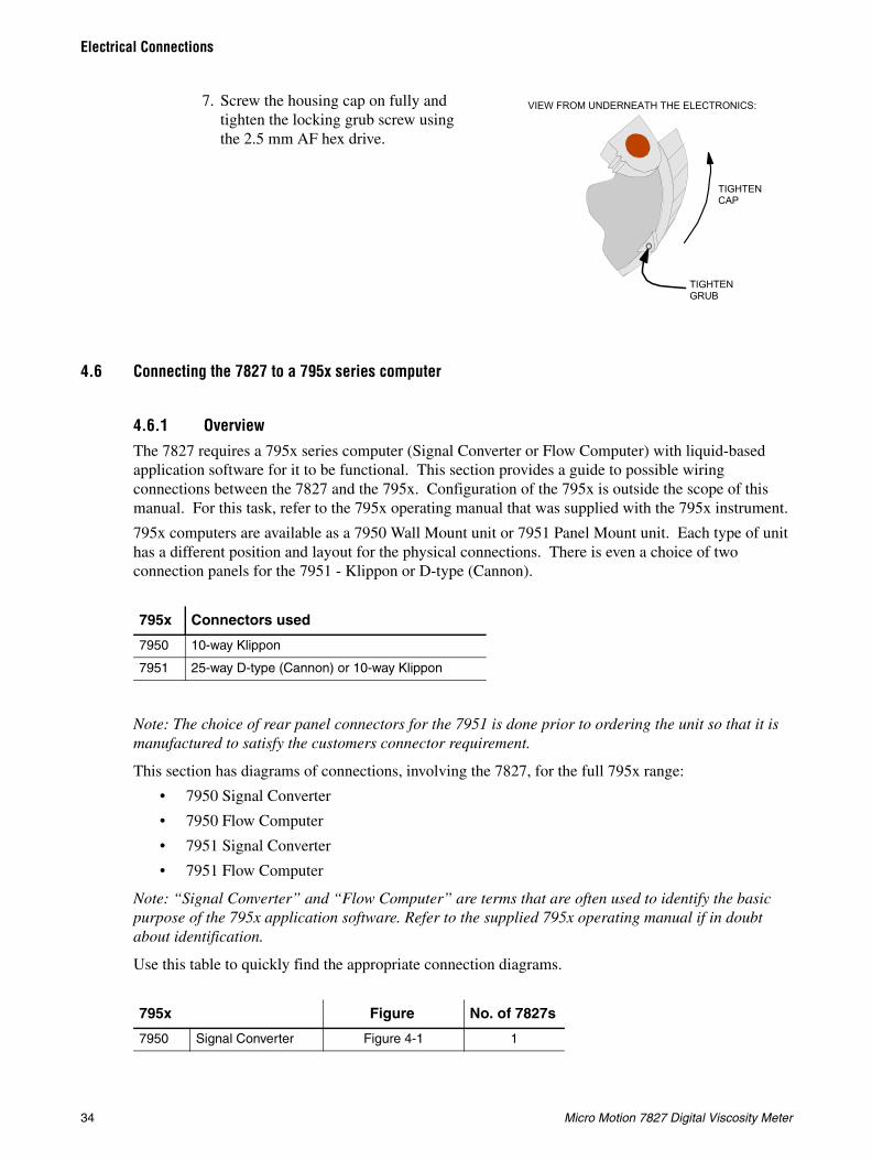
7. Screw the housing cap on fully and tighten the locking grub screw using the 2.5 mm AF hex drive.
795x Connectors used
7950 10-way Klippon
7951 25-way D-type (Cannon) or 10-way Klippon
795x Figure No. of 7827s
7950 Signal Converter Figure 4-1 1
TIGHTENCAP
TIGHTEN GRUB
VIEW FROM UNDERNEATH THE ELECTRONICS:
Installation and Configuration Manual 35
Electrical Connections
Installatio
n (S
ho
rt Stem
)E
lectrical Co
nn
ection
sIn
stallation
(Lo
ng
Stem
)In
trod
uctio
nIn
stallation
(Sh
ort S
tem)
Electrical C
on
nectio
ns
Installatio
n (L
on
g S
tem)
Intro
du
ction
Installatio
n (S
ho
rt Stem
)E
lectrical Co
nn
ection
sIn
stallation
(Lo
ng
Stem
)In
trod
uctio
nIn
stallation
(Sh
ort S
tem)
Electrical C
on
nectio
ns
Installatio
n (L
on
g S
tem)
Intro
du
ction4.6.2 Connection diagrams
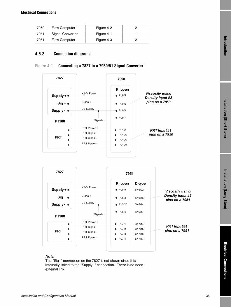
Figure 4-1 Connecting a 7827 to a 7950/51 Signal Converter
7950 Flow Computer Figure 4-2 2
7951 Signal Converter Figure 4-1 1
7951 Flow Computer Figure 4-3 2
Signal -
PRT Signal -
PRT Signal +
PRT Power +
PRT Power -
0V Supply
Signal +
+24V PowerSupply +
Sig +
Supply -
Klippon
PL12/4
7827
PT100
PL12/3
PL12/2
PL12/
PL9/8
PL9/6
PL9/5
PL9/7
Viscosity using Density input #2 pins on a 7950
PRT Input #1 pins on a 7950
7950
PRT
Signal -
PRT Signal -
PRT Signal +
PRT Power +
PRT Power -
0V Supply
Signal +
+24V PowerSupply +
Sig +
Supply -
Klippon D-type
PL7/4
7827
PT100
PL7/3
PL7/2
PL7/1
PL5/10
PL5/3
PL5/9
PL5/4
SK7/17
SK7/16
SK7/15
SK7/14
SK6/24
SK6/16
SK6/22
SK6/17
Viscosity usingDensity input #2pins on a 7951
PRT Input #1 pins on a 7951
7951
PRT
Note : The "Sig -" connection on the 7827 is not shown since it is internally linked to the "Supply -" connection. There is no need external link.
36 Micro Motion 7827 Digital Viscosity Meter
Electrical Connections
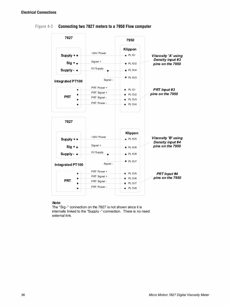
Figure 4-2 Connecting two 7827 meters to a 7950 Flow computer
Signal -
PRT Signal -
PRT Signal +
PRT Power +
PRT Power -
0V Supply
Signal +
+24V PowerSupply +
Sig +
Supply -
Klippon
PL13/8
7827
Integrated PT100
PL13/7
PL13/6
PL13/5
PL10/8
PL10/6
PL10/5
PL10/7
Viscosity 'B' using Density input #4 pins on the 7950
PRT Input #4 pins on the 7950
Signal -
PRT Signal -
PRT Signal +
PRT Power +
PRT Power -
0V Supply
Signal +
+24V PowerSupply +
Sig +
Supply -
Klippon
PL13/4
7827
PL13/3
PL13/2
PL13/
PL10/4
PL10/2
PL10/
PL10/3
Viscosity 'A' using Density input #3 pins on the 7950
PRT Input #3 pins on the 7950
7950
Note : The "Sig -" connection on the 7827 is not shown since it is internally linked to the "Supply -" connection. There is no need external link.
Integrated PT100
PRT
PRT
Installation and Configuration Manual 37
Electrical Connections
Installatio
n (S
ho
rt Stem
)E
lectrical Co
nn
ection
sIn
stallation
(Lo
ng
Stem
)In
trod
uctio
nIn
stallation
(Sh
ort S
tem)
Electrical C
on
nectio
ns
Installatio
n (L
on
g S
tem)
Intro
du
ction
Installatio
n (S
ho
rt Stem
)E
lectrical Co
nn
ection
sIn
stallation
(Lo
ng
Stem
)In
trod
uctio
nIn
stallation
(Sh
ort S
tem)
Electrical C
on
nectio
ns
Installatio
n (L
on
g S
tem)
Intro
du
ction
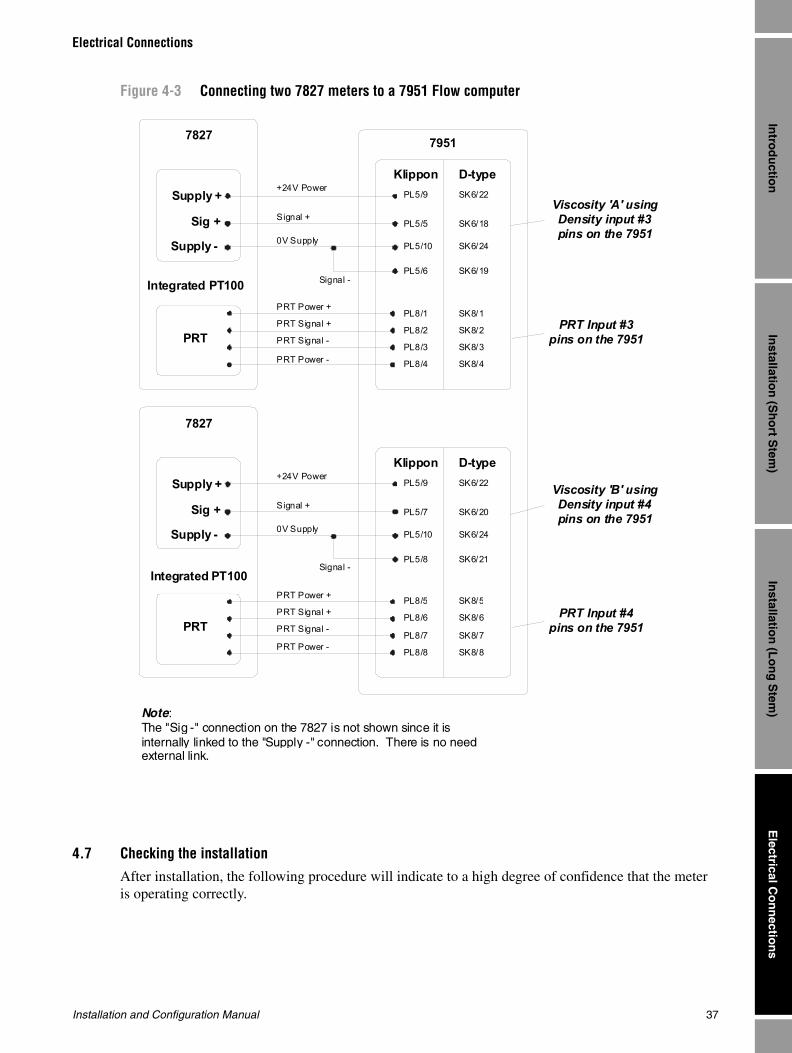
Figure 4-3 Connecting two 7827 meters to a 7951 Flow computer
4.7 Checking the installationAfter installation, the following procedure will indicate to a high degree of confidence that the meter is operating correctly.
Signal -
PRT Signal -
PRT Signal +
PRT Power +
PRT Power -
0V Supply
Signal +
+24V PowerSupply +
Sig +
Supply -
Klippon D-type
PL8/8
7827
Integrated PT100
PL8/7
PL8/6
PL8/5
PL5/10
PL5/7
PL5/9
PL5/8
SK8/8
SK8/7
SK8/6
SK8/5
SK6/24
SK6/20
SK6/22
SK6/21
Viscosity 'B' usingDensity input #4pins on the 7951
PRT Input #4 pins on the 7951
Signal -
PRT Signal -
PRT Signal +
PRT Power +
PRT Power -
0V Supply
Signal +
+24V PowerSupply +
Sig +
Supply -
Klippon D-type
PL8/4
7827
PL8/3
PL8/2
PL8/1
PL5/10
PL5/5
PL5/9
PL5/6
SK8/4
SK8/3
SK8/2
SK8/1
SK6/24
SK6/18
SK6/22
SK6/19
Viscosity 'A' usingDensity input #3pins on the 7951
PRT Input #3 pins on the 7951
7951
Note : The "Sig -" connection on the 7827 is not shown since it is internally linked to the "Supply -" connection. There is no need external link.
Integrated PT100
PRT
PRT
38 Micro Motion 7827 Digital Viscosity Meter
Electrical Connections
Electrical checks
Measure the current consumption and the supply voltage at the meter amplifier. They should be within the following limits:
• Current: 40 mA to 70 mA (Measured in series at the “SUPPLY +” terminal)
• Voltage: 22.8 V to 25.2 V (Measured between” SUPPLY +” and “SUPPLY -” terminals)
Functionality checks
1. When the meter is powered up, a small audible continuous ringing sound can be heard with a “Ping” occurring at 1 second intervals.
2. With the meter clean and dry, and with the tines shielded from the wind, operate it in air and check that the meter frequency output (τB), is as specified on the meter calibration certificate density air point check. If the ambient conditions are not at 20°C (±2°C), use the formula below to calculate the resulting time period:
• tB @ 20°C = tB@ ambient temp – [ 0.11 * ( ambient temp - 20 ) ]
The result (τB) from this equation should now correspond to the air check on the calibration certificate to within ±0.5 μsec.
Note: The air check point is found in the Density Calibration section of the Viscometer calibration certificate.
The τB value can be easily monitored by a 795x computer with the “Health Check” facility. Perform the following 795x front panel keyboard sequence if this facility is required:
a. Press the bottom-right grey MAIN MENU key.
b. Use the DOWN-ARROW key (at the left of the display) to page down through the menu options until “Health Check” (or similar) appears.
c. Select the “Health check” option using the appropriate blue key at the right side of the display.
d. Use the blue DOWN-ARROW key (at the left side) to page down through the menu options until “Time period inputs” (or similar) appears.
e. Select the relevant “Time Period i/p 2”, “Time Period i/p 3” or “Time Period i/p 4” option according to the physical connections made to the 795x (as advised in Section 4.6).
f. Refer to the supplied 795x operating manual for information about front panel key operations and navigating the menu structure.

Installation and Configuration Manual 39
Calib
ration
Ch
eckG
eneral M
ainten
ance
Usin
g 795X
Pro
cessing
Electro
nics
Chapter 5Using 7950/7951 Processing Electronics
5.1 Using the 7950 / 7951 Processing ElectronicsFor details on connecting the 7827 meter to the Micro Motion signal converters and flow computers, refer to the appropriate 795x operating manual.

40 Micro Motion 7827 Digital Viscosity Meter
Using 7950/7951 Processing Electronics
Installation and Configuration Manual 41
Calib
ration
Ch
eckG
eneral M
ainten
ance
Usin
g 795X
Pro
cessing
Electro
nics
Chapter 6Calibration Check
6.1 IntroductionThe following information details the calibration method and performance of the 7827 digital viscosity meter and covers the following:
• Factory calibration
• In-line calibration
• Performance
6.2 Factory calibration
6.2.1 Viscosity
The 7827 meter is calibrated against fluids characterized with prime standards, prior to leaving the factory. The meter may be calibrated over one or a combination of four viscosity ranges detailed below:
• Range: Viscosity range (cP)
• Ultra-low: 0.5 - 10 cP
• Low: 1 - 100 cP
• Medium: 100 - 1,000 cP
• High: 1,000 - 12,500 cP
The 7827 meter’s default calibration is in “free stream” conditions, where the effect of solid boundaries is negligible on the output of the meter. The calibration may also be performed in a “tee-piece,” in which case the part number above is succeeded by a “T”.
Note: A high-range unit cannot be ordered with a tee-piece calibration.
Hygienic units can be calibrated in a 3” hygienic bore if required.
Three fluids are used to establish the general viscosity equation's constants for each viscosity range required. See the Calculated Parameters appendix.
The instrument-under-test is immersed into the calibration fluid which has been previously characterized for viscosity and density with prime standards. Great attention is paid to temperature equalization and fluid homogeneity within the tank before the calibration data is taken. This procedure is repeated for each calibration fluid and for each viscosity calibration range required.
Once the meter has been passed through the necessary fluids, a factory calibration certificate is produced from the measurement data.

42 Micro Motion 7827 Digital Viscosity Meter
Calibration Check
A fourth fluid is used as an overcheck to verify the calibration for each viscosity range. Each check is monitored by the Micro Motion Quality Assurance Department.
6.2.2 DensityThe 7827 meter is calibrated within the standard shroud against Transfer Standard instruments traceable to National Standards, prior to leaving the factory. Three fluids ranging in density from 1 to 1000 kg/m3 are used to establish the general density equation constants. The temperature coefficients are derived from the air point and material properties.
The calibration procedure relies on units being immersed in fluids whose density is defined by Transfer Standards. Great attention is paid to producing temperature equilibrium between the fluid, the unit under test and the Transfer Standard. In this way, accurate calibration coefficients covering the required density range can be produced.
All instruments are over-checked on water to verify the calculation. The check is monitored by the Micro Motion Quality Assurance Department.
Where viscosity correction is concerned, the temperature measurement from each viscosity calibration fluid taken is translated into density through a previous characterization of the fluid using prime standards. This method is used to assess the density offset due to viscosity for each viscosity calibration range not including the 1 to 100 cP range, as the viscosity effect only becomes significant at viscosities greater than 100 cP.
Once the meter has been calibrated with the necessary fluids a factory calibration certificate is produced from the measurement data.
6.2.3 Primary standardsThe fluids used in the viscosity calibration have been characterized for viscosity and density versus temperature in between 15°C and 25°C. This is done using BS/U “U-tube” capillary viscosity meters for kinematic viscosity measurement and pyknometers for density measurements. Both of these methods are Primary Measurement Systems conforming to BS188 and BS733 Part 1 respectively.
The calibration of the calibration fluids is performed under closely controlled laboratory conditions. A calibration certificate is issued. Calibrations are repeated, typically every six months, producing a well documented history of the fluid.
6.2.4 Transfer standardsThe Transfer Standard instruments used in the density calibration are selected instruments which are calibrated by the British Calibration Service Laboratory and certified.
Transfer Standard calibration uses a number of density-certified liquids, one of which is water. The densities of these reference liquids are obtained using the Primary Measurement System whereby glass sinkers of defined volume are weighed in samples of the liquids.
Calibration of the Transfer Standard instruments is performed under closely controlled laboratory conditions. A calibration certificate is issued. Calibrations are repeated, typically every six months, producing a well-documented density standard.
Installation and Configuration Manual 43
Calibration Check
Calib
ration
Ch
eckG
eneral M
ainten
ance
Usin
g 795X
Pro
cessing
Electro
nics
6.3 In-line calibration
6.3.1 ViscosityThe 7827 meter is calibrated to operate in installations where the boundary formed by the surrounding metalwork is at a distance away where it does not influence the viscosity reading from the meter. If the installation is such that an error in viscosity is seen due to the proximity of the metalwork to the tines, an in-line calibration is needed to correct for this source of error.
To perform an in-line calibration it is necessary to know the actual dynamic viscosity and temperature of the calibrating fluid along with both time periods from the meter. The fluid dynamic viscosity at these operating conditions may be determined by using a suitable conventional viscometer/rheometer or by measuring the fluid's kinematic viscosity and multiplying by the fluid's actual density (in g/cc).
The procedure for calculating the new calibration coefficients V1' for the particular viscosity range currently selected is that shown below:
• where V1' = New V1 calibration coefficient for current viscosity range and installation only
• V1 = Original V1 calibration coefficient for current viscosity range
• Q = meter quality factor value in calibration fluid and installation
• ηactual = Actual fluid viscosity (measured from a standard) – (cP)
• ηcalc = Calculated fluid viscosity (using original coefficients and Q below) – (cP)
Note: The value of V1' is now used in the general viscosity equation in the 795x replacing the original values of V1 on the calibration certificate for this application only and for this viscosity range only.
If the process viscosity is variable, the calibration should be tested at the maximum, minimum, and mid-point values of the process viscosity range, to check that the V1 correction is sufficient.
6.3.2 Density
The 7827 meter is calibrated to operate in installations where the boundary formed by the surrounding metalwork is at a distance away where it does not influence the density reading from the meter. If the installation is such that an error in density is seen due to the proximity of the metalwork to the tines, an in-line calibration is needed to correct for this source of error.
To perform an in-line calibration it is necessary to know the actual density and temperature of the calibrating fluid along with the time period B from the meter. The fluid density at these operating conditions may be determined by using using one of the methods outlined below:
For stable liquidsDraw off a sample of the liquid into a suitable container, at the same time note the density and the operating temperature. Measure the density of the sample under defined laboratory conditions using a hydrometer or other suitable equipment.
Note: It is essential that you have a good understanding of the physical properties (temperature coefficient, etc.) of the liquid and that tables of such data are available when using this method.
V1' = V1 + Q2 * ( ηactual - ηcalc )
44 Micro Motion 7827 Digital Viscosity Meter
Calibration Check
For unstable or high-pressure vapor liquids
A pressure pyknometer can be used. The pressure pyknometer and its associated pipework can be coupled to the pipeline so that a sample of the product flows through it. When equilibrium is reached, the meter density reading is noted as the pyknometer is isolated from the sample flow. The pyknometer is removed for weighing to establish the product density. This density result is now compared with the reading from the meter.
For further details on these procedures, reference should be made to:
Energy Institute: HM7. Density, sediment and water. Section 1: General guidance on test methods (formerly PMM Part VII, S1)
1st ed 1996 ISBN 978-0-85293-154-7
Energy Institute: HM8. Density, sediment and water. Section 2: Continuous density measurement (formerly PMM Part VII, S2)
2nd ed Sept 1997 ISBN 978-0-85293-175-2
American Petroleum Institute: Manual of Petroleum Measurement StandardsChapter 14 - Natural Gas Fluids - Section 6: Installing and proving density meters used to measure hydrocarbon liquid with densities between 0.3 and 0.7 g/cc at 15.56°C (60°F) and saturation vapour pressure, April 1991.
The procedure for calculating the new calibration coefficients K0' and K2' from the data derived above is illustrated in Figure 6-1.
6.3.3 Requirements for VOS correctionThis correction only needs to be applied if one or more of the following conditions exist concerning the calibration fluid used and the eventual product fluid being measured:
• The VOS of the calibration fluid is appreciably different to that of the measured fluid.
• The VOS and density of the calibration fluid are significantly displaced from the optimized profile (see the Calculated Parameters appendix).
• The VOS of the product fluid changes significantly with temperature.

Installation and Configuration Manual 45
Calibration Check
Calib
ration
Ch
eckG
eneral M
ainten
ance
Usin
g 795X
Pro
cessing
Electro
nics
Figure 6-1 Density in-line calibration procedure
Note: The values of K0' and K2' are now used in the general density equation in the 795x, replacing the original values of K0 and K2 on the calibration certificate for this application only.
6.4 Performance
6.4.1 ViscosityThe 7827 meter is calibrated for viscosity between 15°C and 25°C and at atmospheric pressure using specified fluids which demonstrate Newtonian behavior.
START
IS VOSREQUIRED?
VOS CORRECTIONMETHOD GRAPHICAL
OR ANALYTICAL SOLUTION?
ANALYTICAL
GRAPHICAL
YES
DETERMINE DENSITYOFFSET dDL FROMVA AND DL (fig B.1)
CALCULATED'L = DL - dDL
IF 0.3g/cc < DL < 1.1g/ccVC = 64.1 + 1.414*DL
IF 1.1g/cc < DL < 1.6g/ccVC = 2346 + 0.660*DL
Dt = __________________DL - K19*(tL - 20)
1 + K18*(tL - 20)
D'L = DLNO
A = VC - VA B = 2900 - DL + A*24.0E+06
D'L = 0.5*[-B + B + 11600*DL ]2
-2 -2
K0' = -1.04 - K1*TA - K2'*TA2
K2' = __________________-1.04 - Dt - K1*(TA - TL)
TA - TL 2 2
Where:• DL= Actual density of calibrating
liquid• Dt= DL corrected for meter
temperature• tL= Temperature of calibrating
liquid• dDL= Density offset of calibrating
liquid from VOS profile (fig. B.1)• D’L= VOS corrected density of
calibrating liquid• τBA= Time period B from the meter
in air (on calibration certificate)• τBL= Time period B in the
calibrating liquid• VA= Actual VOS of calibrating
liquid• VC= Calibration VOS
(For details of the VOS correction method, refer to the Calculated Parameters appendix.)

46 Micro Motion 7827 Digital Viscosity Meter
Calibration Check
Viscosity calibration is effectively immune to temperature or pressure errors when operating with Newtonian fluids.
As a general guide, Table 6-1 shows the accuracy of the 7827 meter:
6.4.2 DensityThe 7827 meter is calibrated for density at 20°C and at atmospheric pressure using specified fluids. When operating at other conditions it is necessary to increase the uncertainty of measurement, either by the magnitude of the offsets if no corrections are applied, or by a fraction of the offsets if corrections are applied.
As a general guide, Table 6-2 lists the sources and magnitudes of the offsets affecting the meter:
For total operational accuracy, the square root of the sum of the squares of each error source is recommended, ie:
Effective total = 1 / [ A2 + B2 + C2 + D2 + E2 ]2
6.5 Calibration certificate example
Note: This is an example only - it is NOT the calibration certificate for your 7827 meter.
Table 6-1 Error sources on indicated viscosity
Error source 7827
A. Instrument accuracy (with Newtonian fluids) ±0.2 cP for 0.5-10 cP range± 1 % of Full Scale Range for other ranges:• ± 1 cP for 1-100 cP range• ± 10 cP for 100-1,000 cP range• ± 200 cP for 1,000-20,000 cP range
Table 6-2 Error sources on indicated density
Error Source 7827
A Instrument accuracy (at calibration conditions) ± 1 kg/m3
B Temperature (uncorrected)Temperature (corrected)
+ 1.5 kg/m3 per °C @ 1000 kg/m3
± 0.1 kg/m3 per °C @ 1000 kg/m3
C Viscosity (uncorrected)Viscosity (corrected)
Described in the Calculated Parameters appendix.± 1 kg/m3 for 1-100 cP± 2 kg/m3 for 100-1,000 cP± 5 kg/m3 for 1,000-20,000 cP
D Velocity Of Sound (uncorrected)Velocity Of Sound (corrected)
Described in the Calculated Parameters appendix.20% of offset
E Long term stability ± 0.5 kg/m3 per year
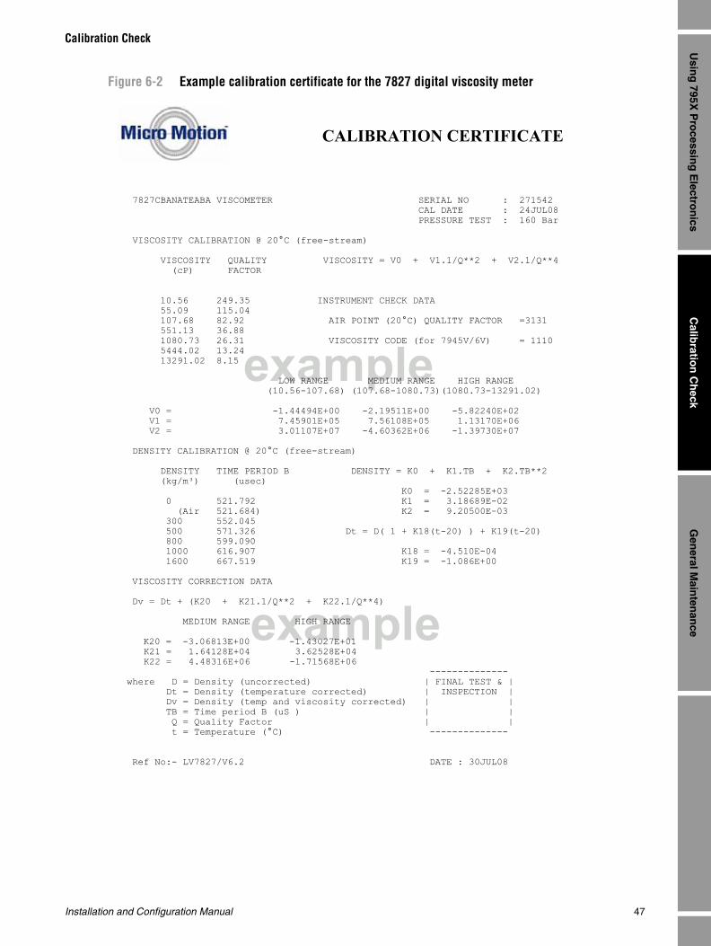
Installation and Configuration Manual 47
Calibration Check
Calib
ration
Ch
eckG
eneral M
ainten
ance
Usin
g 795X
Pro
cessing
Electro
nics
Figure 6-2 Example calibration certificate for the 7827 digital viscosity meter
example
example
CALIBRATION CERTIFICATE
7827CBANATEABA VISCOMETER SERIAL NO : 271542 CAL DATE : 24JUL08 PRESSURE TEST : 160 Bar
VISCOSITY CALIBRATION @ 20°C (free-stream)
VISCOSITY QUALITY VISCOSITY = V0 + V1.1/Q**2 + V2.1/Q**4 (cP) FACTOR
10.56 249.35 INSTRUMENT CHECK DATA 55.09 115.04 107.68 82.92 AIR POINT (20°C) QUALITY FACTOR =3131 551.13 36.88 1080.73 26.31 VISCOSITY CODE (for 7945V/6V) = 1110 5444.02 13.24 13291.02 8.15
LOW RANGE MEDIUM RANGE HIGH RANGE (10.56-107.68) (107.68-1080.73)(1080.73-13291.02)
V0 = -1.44494E+00 -2.19511E+00 -5.82240E+02 V1 = 7.45901E+05 7.56108E+05 1.13170E+06 V2 = 3.01107E+07 -4.60362E+06 -1.39730E+07
DENSITY CALIBRATION @ 20°C (free-stream)
DENSITY TIME PERIOD B DENSITY = K0 + K1.TB + K2.TB**2 (kg/m³) (usec) K0 = -2.52285E+03 0 521.792 K1 = 3.18689E-02 (Air 521.684) K2 = 9.20500E-03 300 552.045 500 571.326 Dt = D( 1 + K18(t-20) ) + K19(t-20) 800 599.090 1000 616.907 K18 = -4.510E-04 1600 667.519 K19 = -1.086E+00
VISCOSITY CORRECTION DATA
Dv = Dt + (K20 + K21.1/Q**2 + K22.1/Q**4)
MEDIUM RANGE HIGH RANGE
K20 = -3.06813E+00 -1.43027E+01 K21 = 1.64128E+04 3.62528E+04 K22 = 4.48316E+06 -1.71568E+06 -------------- where D = Density (uncorrected) | FINAL TEST & | Dt = Density (temperature corrected) | INSPECTION | Dv = Density (temp and viscosity corrected) | | TB = Time period B (uS ) | | Q = Quality Factor | | t = Temperature (°C) --------------
Ref No:- LV7827/V6.2 DATE : 30JUL08

48 Micro Motion 7827 Digital Viscosity Meter
Calibration Check

Installation and Configuration Manual 49
Calib
ration
Ch
eckG
eneral M
ainten
ance
Usin
g 795X
Pro
cessing
Electro
nics
Chapter 7General Maintenance
7.1 IntroductionThis chapter describes which procedures to take in the event of a fault developing with the 7827 digital viscosity meter system.
To use this chapter effectively, follow the options and investigate the possible causes as directed.
If the problem requires more effort than can be described in this document, contact Micro Motion for further assistance.
This chapter covers the following:
• General maintenance
• Fault analysis
• Checking the Signal Converter
• Checking the power consumption
• Checking the installationF
7.2 General maintenanceThe 7827 meter system has no moving parts thereby reducing the maintenance requirements to simple visual checks for leaks, damage to the meter and interrogating the 7950 and 7951 signal converters.
The following procedure is recommended for any periodic maintenance carried out on the system and forms the basis of any fault finding task:
1. Examine the meter, its amplifier housing and cables for any signs of damage or corrosion.
2. Make sure that the spigot connection to the amplifier housing is tight.
3. Check the meter and flanging for signs of leakage.
4. Check that there is no ingress of water/fluid into the amplifier housing.
5. Ensure that the threads on the covers of the amplifier housing are well greased (graphite grease) and that the 'O' rings are in good condition.
The electronics housing is designed for IP 66 environmental rating which means that, providing the caps and plugs are correctly assembled, no moisture or dust is able to penetrate through to the electronics.
The electronics housing is rated for explosion proof to Exd IIC and Class I Division Gas Groups C & D classification. The covers MUST be completely screwed down and, in the case of an explosion proof enclosure application, DO NOT FAIL to tighten the locking screws (Aluminium enclosure 2.5 mm hex A/F; Stainless steel enclosure 2.0 mm hex A/F). (For more information on the safety certification, see the Safety Certification appendix.)
50 Micro Motion 7827 Digital Viscosity Meter
General Maintenance
6. Check that the Signal Converter is providing adequate power to the meter and that the Signal Converter itself is functioning properly.
Check calibrations should be carried out at specified intervals in order to highlight a malfunction or deterioration in meter performance. If a fault or a drop in performance is discovered, further tests – as described in "fault analysis" below – are required to identify the cause of the fault. When a fault has been traced, actions to rectify the fault may include making good any poor connections, replacing the amplifier board, or in extreme cases the complete meter, Signal Converter, or both.
(For details of carrying out a check calibration, refer to Chapter 6).
7.3 Fault analysisA fault may be described as falling in one of three categories:
• Readings unsteady
Normally caused by the presence of gas bubbles around the tines. Severe electrical interference, severe pipeline vibrations, electrical and electronic faults can also cause this effect.
• Readings outside limits
Normally caused by deposition and/or corrosion on the tines. Electrical and electronic faults can also cause this effect.
• Readings not updating
Normally caused by memory locations within the Signal Converter being SET when they should be FREE and by wiring open circuits between Signal Converter and meter.
Checking values in Signal Converter locations is easier than checking electrical power consumption, which in turn is easier than physical inspection, so faults should therefore be considered in this order.
7.3.1 Checking the Signal ConverterAll of the 7827 meter's results are compiled from four main parameters:
• Time period A (τA)
• Time period B (τB)
• Temperature from the PRT
• Quality factor (Q) is obtained from τA & τB
Hence, if instability or inaccuracy of the indicated viscosity or density exists, these parameters should be checked first.
Error on indicated viscosityIf the indicated viscosity is in error, follow the table below and, if necessary, refer to the other tables later in the chapter to find the cause of the fault.
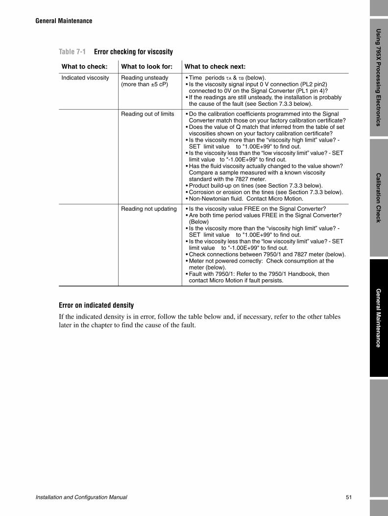
Installation and Configuration Manual 51
General Maintenance
Calib
ration
Ch
eckG
eneral M
ainten
ance
Usin
g 795X
Pro
cessing
Electro
nics
Error on indicated density
If the indicated density is in error, follow the table below and, if necessary, refer to the other tables later in the chapter to find the cause of the fault.
Table 7-1 Error checking for viscosity
What to check: What to look for: What to check next:
Indicated viscosity Reading unsteady(more than ±5 cP)
• Time periods τA & τB (below).• Is the viscosity signal input 0 V connection (PL2 pin2) connected to 0V on the Signal Converter (PL1 pin 4)?
• If the readings are still unsteady, the installation is probably the cause of the fault (see Section 7.3.3 below).
Reading out of limits • Do the calibration coefficients programmed into the Signal Converter match those on your factory calibration certificate?
• Does the value of Q match that inferred from the table of set viscosities shown on your factory calibration certificate?
• Is the viscosity more than the “viscosity high limit” value? - SET limit value to "1.00E+99" to find out.
• Is the viscosity less than the “low viscosity limit” value? - SET limit value to "-1.00E+99" to find out.
• Has the fluid viscosity actually changed to the value shown? Compare a sample measured with a known viscosity standard with the 7827 meter.
• Product build-up on tines (see Section 7.3.3 below).• Corrosion or erosion on the tines (see Section 7.3.3 below).• Non-Newtonian fluid. Contact Micro Motion.
Reading not updating • Is the viscosity value FREE on the Signal Converter?• Are both time period values FREE in the Signal Converter? (Below)
• Is the viscosity more than the “viscosity high limit” value? - SET limit value to "1.00E+99" to find out.
• Is the viscosity less than the “low viscosity limit” value? - SET limit value to "-1.00E+99" to find out.
• Check connections between 7950/1 and 7827 meter (below).• Meter not powered correctly: Check consumption at the meter (below).
• Fault with 7950/1: Refer to the 7950/1 Handbook, then contact Micro Motion if fault persists.

52 Micro Motion 7827 Digital Viscosity Meter
General Maintenance
7.3.2 Checking the power consumptionA lot of information is gained from checking the power consumption at various parts of the circuit between Signal Converter and meter.
Table 7-2 Error checking for density
What to check: What to look for: What to check next:
Indicated density (loc 014)
Reading unsteady(more than ±1kg/m3)
• Time period τB (below).• Is the signal input 0V connection (PL2 pin2) connected to 0V
on the Signal Converter (PL1 pin 4)?• If the reading is still unsteady, the installation is probably the
cause of the fault (see Section 7.3.3 below).
Reading out of limits • Do the calibration coefficients for density programmed into the Signal Converter match those on your factory calibration certificate?
• Is the temperature input FREE and reading correct)?• Do the calibration coefficients for temperature correction on
density programmed into the Signal Converter match those on your factory calibration certificate?
• Do the calibration coefficients for viscosity correction on density programmed into the Signal Converter match those on your factory calibration certificate?
• Have you selected "VOS correction" and left the value of fluid VOS) set to an incorrect value, e.g. 0?
• Is the indicated density greater than the “density high limit” value? - SET limit value to "1.00E+99" to find out.
• Has the fluid density actually changed to the value shown? Compare a sample measured with a known density standard with the 7827 meter.
• Product build-up on tines (see Section 7.3.3 below).• Corrosion or erosion on the tines (see Section 7.3.3 below).
Reading not updating • Is the density value FREE on the Signal Converter?• Are both time period values FREE in the Signal Converter?
(Below)• Are the temp corrected density, viscosity corrected density and
uncorrected density values all free in the signal convereter?• Is the line density greater than the “density high limit” value? -
SET limit value to "1.00E+99" to find out.• Check connections between 7950/1 and 7827 meter (below).• Meter not powered correctly: Check consumption at the meter
(below).• Fault with 7950/1: Refer to the 7950/1 Handbook, then contact
Micro Motion if fault persists.
Table 7-3 Electrical error checking
What to check: What to look for: What to check next:
Voltage at meter:
Across " + " & " - " terminals
22.8 V to 25.2 V dc Correct voltage supplied to meter electronics.
0 V dc There is an open circuit on the power line between the meter and Signal Converter.
Current at meter:
In series with " + " terminal
0 mA Electronics not drawing current:Check wiring for open circuits.
25 mA to 40 mA Electronics drawing the correct amount of current.

Installation and Configuration Manual 53
General Maintenance
Calib
ration
Ch
eckG
eneral M
ainten
ance
Usin
g 795X
Pro
cessing
Electro
nics
7.3.3 Checking the installationThe last check to be made is a physical check of the meter's installation and wetted parts. This means taking the 7827 meter out of the installation and inspecting the tines and pipeline immediately surrounding the flange. This check should serve to confirm the presence of build-up or erosion on the tines.
> 60 mA Electronics drawing excessive current: There is a fault with the maintaining amplifier board. Contact Micro Motion for replacement electronics.
Voltage at viscosity signal input on Signal Converter:
Across PL2, pins 1 & 2
5 V to 15 V dc, switching to 0 V
Correct waveform being sent from the meter.
High or low constant voltage
The meter is not supplying the Signal Converter with the correct waveform. Contact Micro Motion for replacement electronics.
Resistance at PRT:
Across " + SIG " & " - SIG " terminals
80 Ω to 160 Ω Correct resistance lower and upper limits for meter's operating temperature range. For an exact resistance value for the line temperature, see the Product Data appendix.
Out of range The PRT has gone open circuit:Check associated wiring. If unrepairable, contact Micro Motion.
0 Ω The PRT wiring has short circuited:Check associated wiring. If unrepairable, contact Micro Motion.
Table 7-4 Installation checks
What to check: What to look for: What to check next:
Presence of bubbles Leaky pipework. • Flanging correctly aligned, sealed and tightened.
Listen for "popping" inside the line.
• Increase the pipeline pressure.• Align the pipework correctly to prevent
vortices being shed.
Pumps or agitators nearby.
• Pumps and agitators may be generating bubbles from dissolved gases.
Flow rate Determine the flow velocity through the pipeline.
• Refer to the appropriate Installation chapter for your meter to see what maximum flowrate is allowable for the mounting configuration you have chosen.
Determine the distance between the flange face and the inside bore of the pipeline.
• Refer to the appropriate Installation chapter for your meter to see what this distance should be for the mounting configuration you have chosen.
Table 7-3 Electrical error checking continued
What to check: What to look for: What to check next:
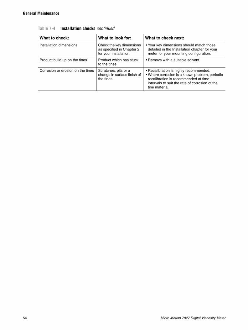
54 Micro Motion 7827 Digital Viscosity Meter
General Maintenance
Installation dimensions Check the key dimensions as specified in Chapter 2 for your installation.
• Your key dimensions should match those detailed in the Installation chapter for your meter for your mounting configuration.
Product build up on the tines Product which has stuck to the tines
• Remove with a suitable solvent.
Corrosion or erosion on the tines Scratches, pits or a change in surface finish of the tines.
• Recalibration is highly recommended.• Where corrosion is a known problem, periodic
recalibration is recommended at time intervals to suit the rate of corrosion of the tine material.
Table 7-4 Installation checks continued
What to check: What to look for: What to check next:

Installation and Configuration Manual 55
Safety C
ertification
Retu
rn P
olicy
Pro
du
ct Data
Calcu
lated P
arameters
Appendix ACalculated Parameters
A.1 IntroductionThe following information details the equations used in the Micro Motion® signal converters to translate the raw data from the meter into fluid parameters and covers the following:
• Viscosity equations
• Quality factor (Q)
• General viscosity equation (η - eta)
• Density equations
• General density equation (ρ - rho)
• Temperature correction equation (ρt)
• Viscosity correction equation (ρv)
• Pressure correction
• Velocity Of Sound correction equation (ρvos)
• Density scaling
• Kinematic viscosity equation
A.2 Viscosity equationsTo derive the fluid's dynamic viscosity the frequency of oscillation at two points on the meter's resonance curve are taken, manipulated to calculate the meter's quality factor (Q) and then calibrated against actual fluid viscosity determined by a prime standard.
(For details of the principle of operation, see Chapter 1.)
The Quality factor from the 7827 meter is calibrated against the fluid’s dynamic viscosity in centiPoise (cP). The order in which the calculations are applied are according to the following.
A.2.1 Quality factor
The meter operates at two time periods (τA and τB) which correspond to the two –3 dB level points on the frequency spectrum. In doing this, one may calculate the meter's quality factor by using the following equation:
Q = 1 / [ ( τA / τB )0.5 - ( τB / τA )0.5 ] [1]
Where:
• Q = Quality factor of meter (no units)
• τA = Time period A of meter (µsec)
• τB = Time period B of meter (µsec)

56 Micro Motion 7827 Digital Viscosity Meter
Calculated Parameters
A.2.2 General viscosity equation
The quality factor of a resonator is proportional to the inverse square root of viscosity. To calibrate the resonator against fluid viscosity, the following quadratic expression is used:
η = V * ( V0 + V1.*X + V2*X2 ) [2]
Where:
• η = Fluid dynamic viscosity (cP)
• V = Dynamic viscosity scaling factor (1 = cP)
• X = 1/Q2 (inverse square of the quality factor)
• V0, V1, V2 = meter calibration coefficients for each calibrated range
(For details of how to display alternative units, refer to the 795x Operating Manual.)
A.3 Density equations
To determine the fluid's density, the smaller of the two time periods (τB) is taken and used in a series of equations to calibrate against actual fluid density determined by a transfer and prime standards. The order in which the calculations are applied according to the following.
A.3.1 General density equationThe time period of a resonator is proportional to the square root of density. To calibrate the resonator against fluid density, the following quadratic expression is used:
ρu = K0 + K1*τB + K2*τB2 [3]
Where:
• ρu = Fluid uncorrected density (kg/m3)
• τB = Time period B of meter (µsec)
• K0, K1, K2 = meter calibration coefficients
The calibration takes place at 20°C and 1 bar.
A.3.2 Temperature correction equationIf the meter operates at a temperature other than 20°C, a correction to the indicated density must be made to account for the change in tine material characteristics with temperature. The following equation is used:
ρt = ρu * [ 1 + K18 * ( t - 20 ) ] + K19 * ( t - 20 ) [4]
Where:
• ρt = Temperature-corrected density (kg/m3)
• ρ = Fluid uncorrected density (kg/m3)
• K18, K19 = Meter calibration constants
• t = Operating temperature (°C)
A.3.3 Viscosity correction equationIf the meter is used in fluids whose viscosity is greater than 100 cP, a correction to the indicated density must be made to account for the offset seen due to the fluid's viscosity. The following equation is used:
Installation and Configuration Manual 57
Calculated Parameters
Safety C
ertification
Retu
rn P
olicy
Pro
du
ct Data
Calcu
lated P
arameters
ρv = ρt - [ K20 + K21*X + K22*X2] [5]
where:
• ρv = Viscosity-corrected density (kg/m3)
• ρt = Temperature-corrected density (kg/m3)
• X = 1/Q2 (inverse square of the quality factor)
• K20, K21, K22 = Meter calibration constants for each calibrated range
Note: Viscosity correction on indicated density is not needed where the fluid viscosity is less than 100 cP as the effect may be considered negligible.
A.3.4 Pressure correction The meter design is such that the influence of the line pressure on the indicated density measurement is a negligible amount and can be ignored.
A.3.5 Velocity Of Sound correction equationIf the Velocity Of Sound (VOS) of the process fluid deviates substantially from the optimised VOS/density profile shown in Figure A-1, it may be desirable to apply a correction. This may be achieved by a simple introduction of an offset using the data from Figure A-1. Adjustment of the value of K0 in the general density equation will achieve this. Alternatively, the following correction equations may be used:
ρvos = ρv * [ 1 + ( 24.0E+06 / (ρv + 2900) ) * ( 1/ VC2 - 1/ VA2 ) ] [6]
Where:
• ρvos = VOS-corrected density (kgm-3)
• ρv = Viscosity-corrected density (kgm-3)
• VC = Calibration VOS (m/s)
• VA = Actual fluid VOS (m/s)
VC may be obtained direct from Figure A-1 or may be calculated as follows:
• VC = 64.1 + 1.414 * ρv – for ρv of 300 kg/m3 to 1100kg/m3 [7]
• VC = 2346 - 0.660 * ρv – for ρv of 1100 kg/m3 to 1600kg/m3 [8]
The value of VC is calculated by the Signal Converter when VOS-correction is applied in the software.

58 Micro Motion 7827 Digital Viscosity Meter
Calculated Parameters
Figure A-1 The Velocity Of Sound (VOS) / density relationship
A.3.6 Density scaling
Once the indicated density has been corrected for temperature, viscosity and VOS, the result is scaled to display density in any set of units. The following expression is used:
ρ = ρvos * K [9]
Where:
• ρ = Displayed density (kg/m3)
• ρvos = VOS-corrected density (kg/m3)
• K = Density scaling factor (1 = kg/m3)
A.4 Kinematic viscosity equationTo derive the fluid's kinematic viscosity the dynamic viscosity and density must be known. The 7827 meter can provide both of these parameters and is therefore able to offer this as a standard output using the following equation:
ν = U * 1000 * [ ( η / V ) / ( ρ / K ) ] [10]
Where:
• ν = Fluid kinematic viscosity (in cS)
• U = Kinematic viscosity scaling factor (1 = cS)
• η = Fluid dynamic viscosity
• V = Dynamic viscosity scaling factor
• ρ = Fluid density
• K = Density scaling factor
The equation includes the dynamic viscosity and density scaling factors to ensure that the kinematic viscosity is always calculated in centiStokes (cS). This result is then scaled by the kinematic viscosity scaling factor (U) to scale the result to display other units of kinematic viscosity. (For details of how to display alternative units refer to the 795x Operating Manual.)
0
500
1,000
1,500
2,000
200 400 600 800 1,000 1,200 1,400 1,600
+1 kg/m3
+0.5 kg/m3
OPTIMISED
-0.5 kg/m3
-1 kg/m3
Density (kg./m3)
Flui
d a c
tua l
vel
ocity
of s
oun d
(m/s
)

Installation and Configuration Manual 59
Safety Certification
Safety C
ertification
Retu
rn P
olicy
Pro
du
ct Data
Calcu
lated P
arameters
Appendix B Safety Certification
B.1 Safety certificationPlease contact Micro Motion if you need to have copies of the latest safety certification for the 7827 digital viscosity meter.

60 Micro Motion 7827 Digital Viscosity Meter
Safety Certification

Installation and Configuration Manual 61
Safety C
ertification
Retu
rn P
olicy
Pro
du
ct Data
Calcu
lated P
arameters
Appendix CProduct Data
C.1 Density / temperature relationship of hydrocarbon products
C.1.1 Crude oil
C.1.2 Refined products
Table C-1 Crude oil
Temp. (°C) Density (kg/m3)60 738.91 765.06 791.94 817.15 843.11 869.01 894.86 920.87 946.46
55 742.96 768.98 794.93 820.83 846.68 872.48 898.24 923.95 949.63
50 747.00 772.89 798.72 824.51 850.25 875.94 901.80 927.23 952.82
45 751.03 776.79 802.50 828.17 853.81 879.40 904.96 930.50 956.00
40 755.05 780.68 806.27 831.83 857.36 882.85 908.32 933.76 959.18
35 759.06 784.57 810.04 835.48 860.90 886.30 911.67 937.02 962.36
30 763.06 788.44 813.79 839.12 864.44 889.73 915.01 940.28 965.53
25 767.05 792.30 817.54 842.76 867.97 893.16 918.35 943.52 968.89
20 771.03 796.18 821.27 846.38 871.49 896.59 921.68 946.77 971.85
15.556 774.56 799.57 824.59 849.60 874.61 899.62 924.63 949.64 974.65
15 775.00 800.00 825.00 850.00 875.00 900.00 925.00 950.00 975.00
10 778.95 803.83 828.72 853.61 878.50 903.41 928.32 953.23 978.15
5 782.90 807.65 832.42 857.20 882.00 906.81 931.62 958.45 981.29
0 786.83 811.46 836.12 860.79 885.49 910.21 934.92 959.66 984.42
Table C-2 Refined products
Temp. (°C) Density (kg/m3)
60 605.51 657.32 708.88 766.17 817.90 868.47 918.99 969.45 1019.87
55 610.59 662.12 713.50 769.97 821.49 872.00 922.46 972.87 1023.24
50 615.51 666.91 718.11 773.75 825.08 875.53 925.92 976.28 1026.60
45 620.49 671.68 722.71 777.53 828.67 879.04 929.38 979.69 1029.96
40 625.45 676.44 727.29 781.30 832.24 882.56 932.84 983.09 1033.32
35 630.40 681.18 731.86 785.86 835.81 886.06 938.28 986.48 1038.67
30 635.33 685.92 736.42 788.81 839.37 889.56 939.72 989.87 1040.01
25 640.24 690.63 740.96 792.55 842.92 893.04 943.16 993.26 1043.35
20 645.13 695.32 745.49 796.28 846.46 896.53 846.58 996.63 1046.68
15.556 649.46 699.48 749.50 799.59 849.61 899.61 949.62 999.63 1049.63

62 Micro Motion 7827 Digital Viscosity Meter
Product Data
The above tables are derived from equations, which form the basis of the data in the Revised Petroleum Measurement Tables (IP 200, ASTM D1250, API 2540 and ISO R91 Addendum 1).
The density temperature relationship used is:
Where: = Density at line temperature t°C (kg/m3)
= Density at base temperature 15°C (kg/m3)
= t°C –15°C (such as t – base temperature)
= Tangent thermal expansion coefficient per °C at base temperature 15°C
The tangent thermal expansion coefficient differs for each of the major groups of hydrocarbons. It is obtained using the following relationship:
Where: K0 and K1 = API factors and are defined as follows:
C.1.3 Platinum resistance law
15 650.00 700.00 750.00 800.00 850.00 900.00 950.00 1000.00 1050.00
10 654.85 704.66 754.50 803.71 853.53 903.47 953.41 1003.36 1053.32
5 659.67 709.30 758.97 807.41 857.04 906.92 956.81 1006.72 1056.63
0 664.47 713.92 763.44 811.10 860.55 910.37 960.20 1010.07 1059.93
Product Density Range (kg/m3) K0 K1
Crude Oil 771 – 981 613.97226 0.00000
Gasolines 654 – 779 346.42278 0.43884
Kerosines 779 – 839 594.54180 0.00000
Fuel Oils 839 – 1075 186.96960 0.48618
Table C-3 Platimum resistance law (To DIN 43 760)
°C Ohms °C Ohms °C Ohms °C Ohms °F Ohms °F Ohms
–50 80.31 5 101.91 60 123.24 115 144.17 0 93.03 100 114.68
–45 82.29 10 103.90 65 125.16 120 146.06 10 95.21 110 116.83
–40 84.27 15 105.85 70 127.07 125 147.94 20 97.39 120 118.97
–35 86.25 20 107.79 75 128.98 130 149.82 30 99.57 130 121.11
–30 88.22 25 109.73 80 130.89 135 151.70 32 100.00 140 123.24
–25 90.19 30 111.67 85 132.80 140 153.58 40 101.74 150 125.37
–20 92.16 35 113.61 90 134.70 145 155.45 50 103.90 160 127.50
–15 94.12 40 115.54 95 136.60 150 157.31 60 106.07 170 129.62
–10 96.09 45 117.47 100 138.50 155 159.18 70 108.23 180 131.74
–5 98.04 50 119.40 105 140.39 160 161.04 80 110.38 190 133.86
0 100.00 55 121.32 110 142.29 165 162.90 90 112.53 200 135.97
Table C-2 Refined products continued
Temp. (°C) Density (kg/m3)
( )[ ]t15t1515
t 8.01exp Δα+Δα−=ρρ
tρ
15ρ
tΔ
15α
215
151015
KKρ
ρ+=α
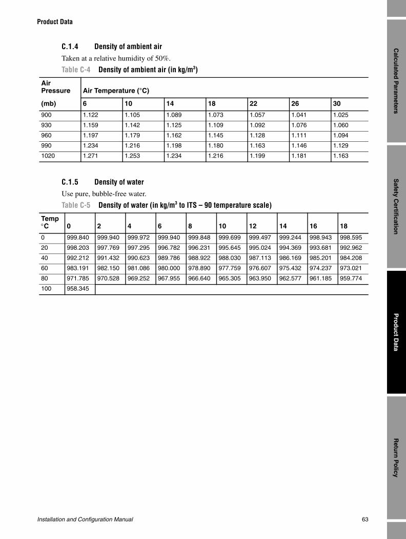
Installation and Configuration Manual 63
Product Data
Safety C
ertification
Retu
rn P
olicy
Pro
du
ct Data
Calcu
lated P
arameters
C.1.4 Density of ambient air
Taken at a relative humidity of 50%.
C.1.5 Density of water Use pure, bubble-free water.
Table C-4 Density of ambient air (in kg/m3)
AirPressure Air Temperature (°C)
(mb) 6 10 14 18 22 26 30
900 1.122 1.105 1.089 1.073 1.057 1.041 1.025
930 1.159 1.142 1.125 1.109 1.092 1.076 1.060
960 1.197 1.179 1.162 1.145 1.128 1.111 1.094
990 1.234 1.216 1.198 1.180 1.163 1.146 1.129
1020 1.271 1.253 1.234 1.216 1.199 1.181 1.163
Table C-5 Density of water (in kg/m3 to ITS – 90 temperature scale)
Temp°C 0 2 4 6 8 10 12 14 16 18
0 999.840 999.940 999.972 999.940 999.848 999.699 999.497 999.244 998.943 998.595
20 998.203 997.769 997.295 996.782 996.231 995.645 995.024 994.369 993.681 992.962
40 992.212 991.432 990.623 989.786 988.922 988.030 987.113 986.169 985.201 984.208
60 983.191 982.150 981.086 980.000 978.890 977.759 976.607 975.432 974.237 973.021
80 971.785 970.528 969.252 967.955 966.640 965.305 963.950 962.577 961.185 959.774
100 958.345

64 Micro Motion 7827 Digital Viscosity Meter
Product Data
C.1.6 Velocity of sound in liquids
Table C-6 Velocity of sound in liquids
Liquid Temp. (t °C) Velocity of Sound
( ms–1)
Rate of Change
( ms–1K–1)
Acetic acid 20 1173 ----
Acetone 20 1190 –4.5
Amyl acetate 29 1173 ----
Aniline 20 1656 –4.0
Benzene 20 1320 –5.0
Blood (horse) 37 1571 ----
Butyl acetate 30 1172 –3.2
Carbon disulphide 25 1142 ----
Carbon tetrachloride 20 940 –3.0
Chlorine 20 850 –3.8
Chlorobenzene 20 1290 –4.3
Chloroform 20 990 –3.3
Ethanol amide 25 1724 –3.4
Ethyl acetate 30 1133 –3.9
Ethyl alcohol 20 1162 –3.6
Formic acid 20 1360 –3.5
Heptane 20 1160 –4.5
n-Hexane 30 1060 ----
Kerosene 25 1315 –3.6
Menthol 50 1271 ----
Methyl acetate 30 1131 –3.7
Methyl alcohol 20 1121 –3.5
Methylene Chloride 25 1070 ----
Nitrogen –189 745 –10.6
Nonane 20 1248 ----
Oil (castor) 19 1500 –4.1
Oil (olive) 22 1440 –2.8
Octane 20 1197 ----
Oxygen –186 950 –6.9
c t/c δδ
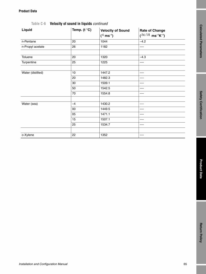
Installation and Configuration Manual 65
Product Data
Safety C
ertification
Retu
rn P
olicy
Pro
du
ct Data
Calcu
lated P
arameters
n-Pentane 20 1044 –4.2
n-Propyl acetate 26 1182 ----
Toluene 20 1320 –4.3
Turpentine 25 1225 ----
Water (distilled) 10 1447.2 ----
20 1482.3 ----
30 1509.1 ----
50 1542.5 ----
70 1554.8 ----
Water (sea) –4 1430.2 ----
00 1449.5 ----
05 1471.1 ----
15 1507.1 ----
25 1534.7 ----
o-Xylene 22 1352 ----
Table C-6 Velocity of sound in liquids continued
Liquid Temp. (t °C) Velocity of Sound
( ms–1)
Rate of Change
( ms–1K–1)c t/c δδ

66 Micro Motion 7827 Digital Viscosity Meter
Product Data
Installation and Configuration Manual 67
Safety C
ertification
Retu
rn P
olicy
Pro
du
ct Data
Calcu
lated P
arameters
Appendix DReturn Policy
D.1 General guidelinesMicro Motion procedures must be followed when returning equipment. These procedures ensure legal compliance with government transportation agencies and help provide a safe working environment for Micro Motion employees. Failure to follow Micro Motion procedures will result in your equipment being refused delivery.
Information on return procedures and forms is available on our web support system at www.micromotion.com, or by phoning the Micro Motion Customer Service department.
D.2 New and unused equipmentOnly equipment that has not been removed from the original shipping package will be considered new and unused. New and unused equipment requires a completed Return Materials Authorization form.
D.3 Used equipmentAll equipment that is not classified as new and unused is considered used. This equipment must be completely decontaminated and cleaned before being returned.
Used equipment must be accompanied by a completed Return Materials Authorization form and a Decontamination Statement for all process fluids that have been in contact with the equipment. If a Decontamination Statement cannot be completed (for example, for food-grade process fluids), you must include a statement certifying decontamination and documenting all foreign substances that have come in contact with the equipment.

68 Micro Motion 7827 Digital Viscosity Meter
Return Policy

Micro Motion USAWorldwide Headquarters7070 Winchester CircleBoulder, CO 80301T +1 303-527-5200
+1 303-522-6277F +1 303-530-8459
Micro Motion SloughEmerson Process Management158 Edinburgh AvenueSlough, Berks, UK SL1 4UET +44 1753 756600F +44 1753 823589
Micro Motion AsiaEmerson Process Management1 Pandan CrescentSingapore 128461Republic of SingaporeT +65 6777-8211F +65 6770-8003
Micro Motion United KingdomEmerson Process Management LimitedHorsfield WayBredbury Industrial EstateStockport SK6 2SU U.K.T +44 0870 240 1978F +44 0800 966 181
Micro Motion JapanEmerson Process Management1-2-5, Higashi ShinagawaShinagawa-kuTokyo 140-0002 JapanT +81 3 5769-6803F +81 3 5769-6844
©2009, Micro Motion, Inc. All rights reserved. P/N MMI-20015440, Rev. AA
*MMI-20015440*
For the latest Micro Motion product specifications, view the PRODUCTS section of our web site at www.micromotion.com