micro mechanical system for system on chip connectivity
TRANSCRIPT

8/3/2019 Micro Mechanical System for System on Chip Connectivity
http://slidepdf.com/reader/full/micro-mechanical-system-for-system-on-chip-connectivity 1/17
101seminartopics.com
INTRODUCTION
MEMS technology has enabled us to realize advanced micro
devices by using processes similar to VLSI technology. When MEMS
devices are combined with other technologies new generation of innovative
technology will b created. This will offer outstanding functionality. Such
technologies will have wide scale applications in fields ranging from
automotive, aerodynamics, hydrodynamics, bio-medical and so forth. The
main challenge is to integrate all these potentially non-compatible
technologies into a single working microsystem that will offer outstanding
functionality.
The use of MEMS technology for permanent, semi permanent or
temporary interconnection of non-compatible technologies like CMOS,
BJT, GaAs, SiGe, and so forth into a System-on-Chip environment can be
described using an example application. It is a hearing instrument in which
an array of acoustical sensors is used to provide dynamic directional
sensitivity that can minimize background noise and reverberation thereby
increasing speech intelligibility for the user. The micro array can provide
dynamically variable directional sensitivity by employing suitable beam
forming and tracking algorithms while implanted completely inside the ear
canal.

8/3/2019 Micro Mechanical System for System on Chip Connectivity
http://slidepdf.com/reader/full/micro-mechanical-system-for-system-on-chip-connectivity 2/17
101seminartopics.com
MEMS ACCOUSTICAL SENSOR ARRAY FOR A
HEARING INSTRUMENT
In this application an array of capacitive type sensors are used in a
hearing instrument to provide dynamic directional sensitivity and speaker
tracking and can be completely implanted in the ear canal. The directional
sensitivity is obtained by the method of beam forming. The microphone
array is developed using MEMS technology and which can be used to form
beam to provide directional sensitivity.
BEAM FORMING USING MICROPHONE ARRAY
The microphone array consists of nine capacitor type microphones
arranged in a 3*3 array and utilizes the classical phased array technique for
beam forming. In this technique, the relative delay or advance in signal
reception is eliminated by applying a delay or advance is that the signal out
puts from different microphones can be added to form a beam as shown in
figure 1.

8/3/2019 Micro Mechanical System for System on Chip Connectivity
http://slidepdf.com/reader/full/micro-mechanical-system-for-system-on-chip-connectivity 3/17
101seminartopics.com
Figure 1. Beam pattern of a transducer array: normal beam
It is also possible to steer the direction of the beam by providing
additional delay factor that is equal to the negative of the relative delay to
the out put of each microphone in the array when a signal arrives from that
direction. Figure 2. illustrates the beam steering concept.

8/3/2019 Micro Mechanical System for System on Chip Connectivity
http://slidepdf.com/reader/full/micro-mechanical-system-for-system-on-chip-connectivity 4/17
101seminartopics.com
Figure 2. Beam pattern of a transducer array: steered beam
Similarly, it is possible to form multiple beams out of the single
array employing different delay factors and use such beams to scan the
direction of the potential speaker. This scanning beam can easily realized
by continuously steering the beam from top to bottom or from left to right
by dynamically changing the steering delay using digital filters. An
algorithm will detect a speech signal above some threshold level and will
steer the main beam towards that direction. The block diagram for such a
system is shown in figure 3.

8/3/2019 Micro Mechanical System for System on Chip Connectivity
http://slidepdf.com/reader/full/micro-mechanical-system-for-system-on-chip-connectivity 5/17
101seminartopics.com
To avoid spatial aliasing at all steering angles the spacing d between the
microphones of the array is required to be
D < πc/ω
= πc/2πf
= λ/2]
Where λ is the wavelength of the incident acoustical signal and f is
the frequency in Hz. c is the velocity.
If the sensor array is to be inserted inside the ear canal, the spacing between
the microphones will be much smaller than the required. This constraint can
be overcome by introducing additional delay factor to compensate for the
difference in delay due to the required spacing d and the delay due to
physical microphone spacing.
SoC
PCI
Bus
Array
Control
Interface
MEMSAcoustical
Array
MEMS
Socket
Interface
CMOSA/D
Converter
Analog CMOSSignal
Conditioning
Digital
Beamforming
& Beam
Steering
Digital
Signal
Processing
Figure 3: Block Diagram of Hearing Aid Instrument

8/3/2019 Micro Mechanical System for System on Chip Connectivity
http://slidepdf.com/reader/full/micro-mechanical-system-for-system-on-chip-connectivity 6/17
101seminartopics.com
MEMS MICROPACKAGING SOLUTION
The MEMS technology can be used to create necessary structures
for die level integration of MEMS devices or components and CMOS or
non-CMOS, like BJT, GaAs, and Silicon-germanium devices. The basic
structure of the proposed mechanism is a socket submodule (figure 4) that
holds a die or device. The required no of submodules can be stacked
vertically or horizontally to realize a completely system in a micropackage.
Figure 4a. 3D model of socket submodule

8/3/2019 Micro Mechanical System for System on Chip Connectivity
http://slidepdf.com/reader/full/micro-mechanical-system-for-system-on-chip-connectivity 7/17
101seminartopics.com
Figure 4b. top view of socket submodule
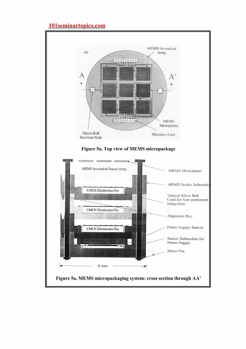
Connectivity between submodules is achieved by means of
microbus card (figure 6.) constructed with heat deformed, gold coated
polysilicon cantilever microspring contacts and platinum coated microrails
fabricated inside an interconnection channel that is presented in each socket
submodule. An illustration of the micropackaging system is shown in
figure 5.
8/3/2019 Micro Mechanical System for System on Chip Connectivity
http://slidepdf.com/reader/full/micro-mechanical-system-for-system-on-chip-connectivity 8/17
101seminartopics.com
Figure 5a. Top view of MEMS micropackage
Figure 5a. MEMS micropackaging system: cross section through AA’

8/3/2019 Micro Mechanical System for System on Chip Connectivity
http://slidepdf.com/reader/full/micro-mechanical-system-for-system-on-chip-connectivity 9/17
101seminartopics.com
Microorganisms and moisture inside the ear canal may
contaminate the microsensor array. This can be helped by the submodule
type sensor array, which can be removed easily for cleaning or replacement.
The submodules are connected by means of a MEMS microbus
with gold coated polysilicon cantilever microspring contacts and platinum
coated microrails fabricated inside an interconnection channel that is
presented in each socket submodule. Figure 6 shows the 3D model of
microbus
Figure 6. 3D model of MEMS microbus card

8/3/2019 Micro Mechanical System for System on Chip Connectivity
http://slidepdf.com/reader/full/micro-mechanical-system-for-system-on-chip-connectivity 10/17
101seminartopics.com
DIE TESTING CONFIGURATION
The concept of socket submodules and connectivity can also be
used in a die testing platform. The establishment of temporary connectivity
for testing a die without exposing the die to otherwise harmful energy
sources or contaminations during the test cycles is a major technological
challenge. The MEMS submodule can be reconfigured to establish
temporary connectivity for die testing with out exposing the die to any
contamination while carrying out necessary test procedures. Figure 7
illustrates the die testing configuration using MEMS socket type structures.
Figure 7. MEMS die testing configuration

8/3/2019 Micro Mechanical System for System on Chip Connectivity
http://slidepdf.com/reader/full/micro-mechanical-system-for-system-on-chip-connectivity 11/17
101seminartopics.com
In this set up, two different type of MEMS sockets are used: a
fixed one connected permanently to a Tester-on-Chip (ToC),which is a die
testing SoC using an enabling gold–to-gold thermo sonic bonding
technology and a removable socket that acts a die specific carrier. The
contact springs on both sides of the removable socket undergo deformation
due to a compression mass on the top of the die and generate the necessary
contact force. The removable MEMS socket can be redesigned to connect a
die that is larger than the ToC. This makes the system a flexible one. The
major design objectives of contact spring mechanism is to develop a proper
–contact force, low-contact resistance, small area, and short contact path
while having the ability to tolerate some torsional misalignment. Another
important requirement is to maintain the contact surface that will remain
reasonably flat even under torsional deformation to realize a higher contact
area. Based on these constraints designs two of contact springs are given in
figure 8.

8/3/2019 Micro Mechanical System for System on Chip Connectivity
http://slidepdf.com/reader/full/micro-mechanical-system-for-system-on-chip-connectivity 12/17
101seminartopics.com
Figure 8. Two types of micro spring contacts
ADVANTAGES AND DISADVANTAGES
ADVANTAGES
High efficiency
Cost effective
Flexible
High accuracy precision
DIS ADVANTAGES
Complex design
Complex fabrication procedures

8/3/2019 Micro Mechanical System for System on Chip Connectivity
http://slidepdf.com/reader/full/micro-mechanical-system-for-system-on-chip-connectivity 13/17
101seminartopics.com
CONCLUSION
MEMS technology offers wide range application in fields like
biomedical, aerodynamics, thermodynamics and telecommunication and so
forth. MEMS technology can be used to fabricate both application specific
devices and the associated micropackaging system that will allow for the
integration of devices or circuits, made with non compatible technologies,
with a SoC environment. The MEMS technology allows permanent, semi
permanent and temporary connectivity. The integration of MEMS to
present technology will give way to cutting edge technology that will give
outstanding functionality and far reaching efficiency regarding space,
accuracy precision, cost, and will wide range applications. Describing
typical application of MEMS in a hearing instrument application the
flexibility and design challenges and various innovative features of MEMS
technology is made to understand. In the hearing aid instrument
microphone arrays are used to produce directional sensitivity and improve
speech intelligibility. The various components and necessary signal
conditioning algorithms are implemented in a custom micropackaging that
can be implanted inside the ear canal is described.

8/3/2019 Micro Mechanical System for System on Chip Connectivity
http://slidepdf.com/reader/full/micro-mechanical-system-for-system-on-chip-connectivity 14/17
101seminartopics.com
REFERENCES
1. Sazzadur Choudhury,M. Ahmadi, and W.C. Miller ,
Micromechanical system for System-on-Chip Connectivity’, IEEE
Circuits and Sytems, September 2002
2. New battery may jump-start MEMS usage, ISA InTech April 2002
BIBLIOGRAPHY
1. www.darpa.mil
2. www.sanyo.co.jp

8/3/2019 Micro Mechanical System for System on Chip Connectivity
http://slidepdf.com/reader/full/micro-mechanical-system-for-system-on-chip-connectivity 15/17
101seminartopics.com
ABSTRACT
Micromechanical systems can be combined with microelectronics,
photonics or wireless capabilities new generation of Microsystems can be
developed which will offer far reaching efficiency regarding space,
accuracy, precision and so forth. Micromechanical systems (MEMS)
technology can be used fabricate both application specific devices and the
associated micro packaging systems that will allow for the integration of
devices or circuits, made with non-compatible technologies, with a System-
on-Chip environment. The MEMS technology can be used for permanent,
semi permanent or temporary interconnection of sub modules in a System-
on-Chip implementation. The interconnection of devices using MEMS
technology is described with the help of a hearing instrument application
and related micropackaging.

8/3/2019 Micro Mechanical System for System on Chip Connectivity
http://slidepdf.com/reader/full/micro-mechanical-system-for-system-on-chip-connectivity 16/17
101seminartopics.com
CONTENTS
1. INTRODUCTION 1
2. MEMS ACCOUSTICAL SENSOR ARRAY FOR A HEARING
INSTRUMENT 2
BEAM FORMING USING MICROPHONE ARRAY 2
3. MEMS MICROPACKAGING SOLUTION 6
4. DIE TESTING CONFIGURATION 10
5. ADVANTAGES AND DISADVANTAGES 12
6. CONCLUSION 13
7. REFERENCES 14
8. BIBLIOGRAPHY 14

8/3/2019 Micro Mechanical System for System on Chip Connectivity
http://slidepdf.com/reader/full/micro-mechanical-system-for-system-on-chip-connectivity 17/17
101seminartopics.com
ACKNOWLEDGEMENT
I extend my sincere gratitude towards Prof . P.Sukumaran Head of
Department for giving us his invaluable knowledge and wonderful technical
guidance
I express my thanks to Mr. Muhammed kutty our group tutor and
also to our staff advisor Ms. Biji Paul for their kind co-operation and
guidance for preparing and presenting this seminar.
I also thank all the other faculty members of AEI department and my
friends for their help and support.