micro-bath user’s guide - instrumart · hart does not warrant calibrations on the micro-bath....
TRANSCRIPT

7103Micro-Bath
User’s Guide
Rev. 5B0202
Hart Scientific

Limited Warranty & Limitation of Liability
Each product from Fluke's Hart Scientific Division ("Hart") is warranted to be free from defects in mate-rial and workmanship under normal use and service. The warranty period is one year for the Micro-Bath.The warranty period begins on the date of the shipment. Parts, product repairs, and services are warrantedfor 90 days. The warranty extends only to the original buyer or end-user customer of a Hart authorizedreseller, and does not apply to fuses, disposable batteries or to any other product which, in Hart's opinion,has been misused, altered, neglected, or damaged by accident or abnormal conditions of operation orhandling. Hart warrants that software will operate substantially in accordance with its functional specifi-cations for 90 days and that it has been properly recorded on non-defective media. Hart does not warrantthat software will be error free or operate without interruption. Hart does not warrant calibrations on theMicro-Bath.
Hart authorized resellers shall extend this warranty on new and unused products to end-user customersonly but have no authority to extend a greater or different warranty on behalf of Hart. Warranty support isavailable if product is purchased through a Hart authorized sales outlet or Buyer has paid the applicableinternational price. Hart reserves the right to invoice Buyer for importation costs of repairs/replacementparts when product purchased in one country is submitted for repair in another country.
Hart's warranty obligation is limited, at Hart's option, to refund of the purchase price, free of charge re-pair, or replacement of a defective product which is returned to a Hart authorized service center withinthe warranty period.
To obtain warranty service, contact your nearest Hart authorized service center or send the product, witha description of the difficulty, postage, and insurance prepaid (FOB Destination), to the nearest Hart au-thorized service center. Hart assumes no risk for damage in transit. Following warranty repair, the prod-uct will be returned to Buyer, transportation prepaid (FOB Destination). If Hart determines that thefailure was caused by misuse, alteration, accident or abnormal condition or operation or handling, Hartwill provide an estimate or repair costs and obtain authorization before commencing the work. Followingrepair, the product will be returned to the Buyer transportation prepaid and the Buyer will be billed forthe repair and return transportation charges (FOB Shipping Point).
THIS WARRANTY IS BUYER'S SOLE AND EXCLUSIVE REMEDY AND IS IN LIEU OF ALLOTHER WARRANTIES, EXPRESS OR IMPLIED, INCLUDING BUT NOT LIMITED TO ANY IM-PLIED WARRANTY OF MERCHANTABILITY OR FITNESS FOR A PARTICULAR PURPOSE.HART SHALL NOT BE LIABLE FOR ANY SPECIAL, INDIRECT, INCIDENTAL. OR CONSE-QUENTIAL DAMAGES OR LOSSES, INCLUDING LOSS OF DATA, WHETHER ARISING FROMBREACH OF WARRANTY OR BASED ON CONTRACT, TORT, RELIANCE OR ANY OTHERTHEORY.
Since some countries or states do not allow limitation of the term of an implied warranty, or exclusion orlimitation of incidental or consequential damages, the limitations and exclusions of this warranty may notapply to every buyer. If any provision of this Warranty is held invalid or unenforceable by a court of com-petent jurisdiction, such holding will not affect the validity or enforceability of any other provision.
Fluke Corporation, Hart Scientific Division799 E. Utah Valley Drive American Fork, UT 84003-9775 USAPhone: +1.801.763.1600Telefax: +1.801.763.1010Email: [email protected]
www.hartscientific.comSubject to change without notice. Copyright © 2005 Printed in USA
Table of Contents
1 Before You Start . . . . . . . . . . . . . . . . . . . . . . . . . . 11.1 Symbols Used . . . . . . . . . . . . . . . . . . . . . . . . . . . . 1
1.2 Safety Information . . . . . . . . . . . . . . . . . . . . . . . . . . 21.2.1 Warnings . . . . . . . . . . . . . . . . . . . . . . . . . . . . . . . . . . . . . 21.2.2 Cautions . . . . . . . . . . . . . . . . . . . . . . . . . . . . . . . . . . . . . 4
1.3 Authorized Service Centers. . . . . . . . . . . . . . . . . . . . . . 5
2 Introduction . . . . . . . . . . . . . . . . . . . . . . . . . . . . 7
3 Specifications and Environmental Conditions . . . . . . . . . . 93.1 Specifications . . . . . . . . . . . . . . . . . . . . . . . . . . . . . 9
3.2 Environmental Conditions . . . . . . . . . . . . . . . . . . . . . . 9
4 Quick Start . . . . . . . . . . . . . . . . . . . . . . . . . . . . 114.1 Unpacking . . . . . . . . . . . . . . . . . . . . . . . . . . . . . . 11
4.2 Set-Up . . . . . . . . . . . . . . . . . . . . . . . . . . . . . . . . 11
4.3 Power . . . . . . . . . . . . . . . . . . . . . . . . . . . . . . . . 12
4.4 Setting the Temperature . . . . . . . . . . . . . . . . . . . . . . . 12
5 Installation . . . . . . . . . . . . . . . . . . . . . . . . . . . . 135.1 Bath Environment . . . . . . . . . . . . . . . . . . . . . . . . . . 13
5.2 “Dry-out” Period . . . . . . . . . . . . . . . . . . . . . . . . . . 13
5.3 Bath Preparation and Filling . . . . . . . . . . . . . . . . . . . . 13
5.4 Power . . . . . . . . . . . . . . . . . . . . . . . . . . . . . . . . 14
6 Bath Use . . . . . . . . . . . . . . . . . . . . . . . . . . . . . . 156.1 General . . . . . . . . . . . . . . . . . . . . . . . . . . . . . . . 15
6.2 Comparison Calibration . . . . . . . . . . . . . . . . . . . . . . . 15
6.3 Calibration of Multiple Probes . . . . . . . . . . . . . . . . . . . 16
7 Parts and Controls . . . . . . . . . . . . . . . . . . . . . . . . 177.1 Back Panel. . . . . . . . . . . . . . . . . . . . . . . . . . . . . . 17
7.2 Front Panel . . . . . . . . . . . . . . . . . . . . . . . . . . . . . 18
7.3 Accessories . . . . . . . . . . . . . . . . . . . . . . . . . . . . . 197.3.1 Transport/Pour Access Lid . . . . . . . . . . . . . . . . . . . . . . . . . . . 197.3.2 Access Cover . . . . . . . . . . . . . . . . . . . . . . . . . . . . . . . . . . 20
iii

7.3.3 Probe Basket . . . . . . . . . . . . . . . . . . . . . . . . . . . . . . . . . . 207.3.4 Stir Bar . . . . . . . . . . . . . . . . . . . . . . . . . . . . . . . . . . . . . 21
8 General Operation . . . . . . . . . . . . . . . . . . . . . . . . 238.1 Changing Display Units . . . . . . . . . . . . . . . . . . . . . . . 23
8.2 Switching to 230V Operation . . . . . . . . . . . . . . . . . . . . 23
8.3 Bath Fluid . . . . . . . . . . . . . . . . . . . . . . . . . . . . . . 238.3.1 Temperature Range . . . . . . . . . . . . . . . . . . . . . . . . . . . . . . . 238.3.2 Viscosity. . . . . . . . . . . . . . . . . . . . . . . . . . . . . . . . . . . . . 248.3.3 Specific Heat . . . . . . . . . . . . . . . . . . . . . . . . . . . . . . . . . . 248.3.4 Thermal Conductivity . . . . . . . . . . . . . . . . . . . . . . . . . . . . . . 248.3.5 Thermal Expansion . . . . . . . . . . . . . . . . . . . . . . . . . . . . . . . 248.3.6 Electrical Resistivity . . . . . . . . . . . . . . . . . . . . . . . . . . . . . . 248.3.7 Fluid Lifetime . . . . . . . . . . . . . . . . . . . . . . . . . . . . . . . . . . 258.3.8 Safety . . . . . . . . . . . . . . . . . . . . . . . . . . . . . . . . . . . . . . 258.3.9 Cost . . . . . . . . . . . . . . . . . . . . . . . . . . . . . . . . . . . . . . . 258.3.10 Commonly Used Fluids . . . . . . . . . . . . . . . . . . . . . . . . . . . . . 25
8.3.10.1 Water (Distilled) . . . . . . . . . . . . . . . . . . . . . . . . . . . . . . . . . . . . 258.3.10.2 Mineral Oil . . . . . . . . . . . . . . . . . . . . . . . . . . . . . . . . . . . . . . . 268.3.10.3 Silicone Oil (Dow Corning 200.05, 200.10, 200.20) . . . . . . . . . . . . . . . . . . 26
8.3.11 Fluid Characteristics Charts. . . . . . . . . . . . . . . . . . . . . . . . . . . 268.3.11.1 Limitations and Disclaimer . . . . . . . . . . . . . . . . . . . . . . . . . . . . . . . 268.3.11.2 About the Graph . . . . . . . . . . . . . . . . . . . . . . . . . . . . . . . . . . . . 28
8.4 Stirring . . . . . . . . . . . . . . . . . . . . . . . . . . . . . . . 29
8.5 Power . . . . . . . . . . . . . . . . . . . . . . . . . . . . . . . . 30
8.6 Thermal Electric Devices (TED) . . . . . . . . . . . . . . . . . . 30
8.7 Fluid Drain . . . . . . . . . . . . . . . . . . . . . . . . . . . . . 30
8.8 Temperature Controller . . . . . . . . . . . . . . . . . . . . . . . 30
9 Controller Operation . . . . . . . . . . . . . . . . . . . . . . . 339.1 Well Temperature . . . . . . . . . . . . . . . . . . . . . . . . . . 33
9.2 Temperature Set-point . . . . . . . . . . . . . . . . . . . . . . . . 339.2.1 Programmable Set-points . . . . . . . . . . . . . . . . . . . . . . . . . . . . 339.2.2 Set-point Value . . . . . . . . . . . . . . . . . . . . . . . . . . . . . . . . . 359.2.3 Temperature Scale Units . . . . . . . . . . . . . . . . . . . . . . . . . . . . 35
9.3 Scan . . . . . . . . . . . . . . . . . . . . . . . . . . . . . . . . . 369.3.1 Scan Control . . . . . . . . . . . . . . . . . . . . . . . . . . . . . . . . . . 369.3.2 Scan Rate . . . . . . . . . . . . . . . . . . . . . . . . . . . . . . . . . . . . 36
9.4 Temperature Display Hold . . . . . . . . . . . . . . . . . . . . . 379.4.1 Hold Temperature Display . . . . . . . . . . . . . . . . . . . . . . . . . . . 379.4.2 Mode Setting . . . . . . . . . . . . . . . . . . . . . . . . . . . . . . . . . . 379.4.3 Switch Wiring . . . . . . . . . . . . . . . . . . . . . . . . . . . . . . . . . . 389.4.4 Switch Test Example . . . . . . . . . . . . . . . . . . . . . . . . . . . . . . 38
9.5 Secondary Menu. . . . . . . . . . . . . . . . . . . . . . . . . . . 38
9.6 Thermal Electric Device (TED) . . . . . . . . . . . . . . . . . . . 39
iv

9.7 Proportional Band . . . . . . . . . . . . . . . . . . . . . . . . . . 39
9.8 Controller Configuration . . . . . . . . . . . . . . . . . . . . . . 409.8.1 Operating Parameters . . . . . . . . . . . . . . . . . . . . . . . . . . . . . . 40
9.8.1.1 High Limit . . . . . . . . . . . . . . . . . . . . . . . . . . . . . . . . . . . . . . . 419.8.1.2 Stir Speed . . . . . . . . . . . . . . . . . . . . . . . . . . . . . . . . . . . . . . . . 41
9.8.2 Serial Interface Parameters . . . . . . . . . . . . . . . . . . . . . . . . . . . 419.8.2.1 Baud Rate . . . . . . . . . . . . . . . . . . . . . . . . . . . . . . . . . . . . . . . . 429.8.2.2 Sample Period. . . . . . . . . . . . . . . . . . . . . . . . . . . . . . . . . . . . . . 429.8.2.3 Duplex Mode . . . . . . . . . . . . . . . . . . . . . . . . . . . . . . . . . . . . . . 429.8.2.4 Linefeed . . . . . . . . . . . . . . . . . . . . . . . . . . . . . . . . . . . . . . . . . 43
9.8.3 Calibration Parameters . . . . . . . . . . . . . . . . . . . . . . . . . . . . . 439.8.3.1 Hard Cutout . . . . . . . . . . . . . . . . . . . . . . . . . . . . . . . . . . . . . . . 449.8.3.2 R0 . . . . . . . . . . . . . . . . . . . . . . . . . . . . . . . . . . . . . . . . . . . . 449.8.3.3 ALPHA . . . . . . . . . . . . . . . . . . . . . . . . . . . . . . . . . . . . . . . . . 449.8.3.4 DELTA . . . . . . . . . . . . . . . . . . . . . . . . . . . . . . . . . . . . . . . . . 449.8.3.5 BETA . . . . . . . . . . . . . . . . . . . . . . . . . . . . . . . . . . . . . . . . . . 44
10 Digital Communication Interface . . . . . . . . . . . . . . . . 4510.1 Serial Communications . . . . . . . . . . . . . . . . . . . . . . . 45
10.1.1 Wiring . . . . . . . . . . . . . . . . . . . . . . . . . . . . . . . . . . . . . . 4510.1.2 Setup . . . . . . . . . . . . . . . . . . . . . . . . . . . . . . . . . . . . . . 45
10.1.2.1 Baud Rate . . . . . . . . . . . . . . . . . . . . . . . . . . . . . . . . . . . . . . . . 4610.1.2.2 Sample Period. . . . . . . . . . . . . . . . . . . . . . . . . . . . . . . . . . . . . . 4610.1.2.3 Duplex Mode . . . . . . . . . . . . . . . . . . . . . . . . . . . . . . . . . . . . . . 4610.1.2.4 Linefeed . . . . . . . . . . . . . . . . . . . . . . . . . . . . . . . . . . . . . . . . . 46
10.1.3 Serial Operation . . . . . . . . . . . . . . . . . . . . . . . . . . . . . . . . . 46
10.2 Interface Commands . . . . . . . . . . . . . . . . . . . . . . . . 47
11 Test Probe Calibration . . . . . . . . . . . . . . . . . . . . . . 5111.1 Calibrating a Single Probe. . . . . . . . . . . . . . . . . . . . . . 51
11.2 Stabilization and Accuracy . . . . . . . . . . . . . . . . . . . . . 51
12 Calibration Procedure . . . . . . . . . . . . . . . . . . . . . . 5312.1 Calibration Points . . . . . . . . . . . . . . . . . . . . . . . . . . 53
12.2 Calibration Procedure . . . . . . . . . . . . . . . . . . . . . . . . 5312.2.1 Compute DELTA . . . . . . . . . . . . . . . . . . . . . . . . . . . . . . . . 5312.2.2 Compute R0 & ALPHA. . . . . . . . . . . . . . . . . . . . . . . . . . . . . 5412.2.3 Compute BETA . . . . . . . . . . . . . . . . . . . . . . . . . . . . . . . . . 5412.2.4 Accuracy & Repeatability. . . . . . . . . . . . . . . . . . . . . . . . . . . . 55
13 Maintenance . . . . . . . . . . . . . . . . . . . . . . . . . . . 57
14 Troubleshooting. . . . . . . . . . . . . . . . . . . . . . . . . . 5914.1 Troubleshooting Problems, Possible Causes, and Solutions . . . . 59
14.2 Comments . . . . . . . . . . . . . . . . . . . . . . . . . . . . . . 6014.2.1 EMC Directive . . . . . . . . . . . . . . . . . . . . . . . . . . . . . . . . . 6014.2.2 Low Voltage Directive (Safety) . . . . . . . . . . . . . . . . . . . . . . . . . 60
v

vi
Figures
Figure 1 7103 back panel and bottom . . . . . . . . . . . . . . . . . . . . . . . 17Figure 2 Bath Lids and Lid Parts . . . . . . . . . . . . . . . . . . . . . . . . . 19Figure 3 7103 Front Panel . . . . . . . . . . . . . . . . . . . . . . . . . . . . . 19Figure 4 Probe Basket . . . . . . . . . . . . . . . . . . . . . . . . . . . . . . . 20Figure 5 Stir Bar . . . . . . . . . . . . . . . . . . . . . . . . . . . . . . . . . . 21Figure 6 Chart of Various Bath Fluids . . . . . . . . . . . . . . . . . . . . . . . 28Figure 7 Controller Operation Flowchart . . . . . . . . . . . . . . . . . . . . . 34Figure 8 Serial Cable Wiring . . . . . . . . . . . . . . . . . . . . . . . . . . . 45

vii
Tables
Table 1 International Electrical Symbols . . . . . . . . . . . . . . . . . . . . . 1Table 2 Specifications . . . . . . . . . . . . . . . . . . . . . . . . . . . . . . . 9Table 3 Table of Various Bath Fluids . . . . . . . . . . . . . . . . . . . . . . . 27Table 4 Nominal Stirrer Motor Settings With Different Liquids . . . . . . . . . 30Table 5 Controller Communications Commands . . . . . . . . . . . . . . . . . 48Table 5 Controller Communications Commands continued . . . . . . . . . . . 49

1 Before You Start
1.1 Symbols UsedTable 1 lists the International Electrical Symbols. Some or all of these symbolsmay be used on the instrument or in this manual.
Symbol Description
AC (Alternating Current)
AC-DC
Battery
CE Complies with European Union Directives
DC
Double Insulated
Electric Shock
Fuse
PE Ground
Hot Surface (Burn Hazard)
Read the User’s Manual (Important Information)
Off
On
1
1
Before You Start
Table 1 International Electrical Symbols

Symbol Description
Canadian Standards Association
OVERVOLTAGE (Installation) CATEGORY II, Pollution Degree 2 per IEC1010-1 re-fers to the level of Impulse Withstand Voltage protection provided. Equipment ofOVERVOLTAGE CATEGORY II is energy-consuming equipment to be supplied fromthe fixed installation. Examples include household, office, and laboratory appliances.
C-TIC Australian EMC Mark
The European Waste Electrical and Electronic Equipment (WEEE) Directive(2002/96/EC) mark.
1.2 Safety InformationUse this instrument only as specified in this manual. Otherwise, the protectionprovided by the instrument may be impaired.
The following definitions apply to the terms “Warning” and “Caution”.
• “Warning” identifies conditions and actions that may pose hazards to theuser.
• “Caution” identifies conditions and actions that may damage the instru-ment being used.
1.2.1 Warnings
Disclaimer: Hart Scientific manufactures instruments for the purpose oftemperature calibration. Instruments used for applications other than cali-bration are used at the discretion and sole responsibility of the customer.Hart Scientific cannot accept any responsibility for the use of instrumentsfor any application other than temperature calibration.
GENERAL
DO NOT use the instrument for any application other than calibration work.The instrument was designed for temperature calibration. Any other use of theunit may cause unknown hazards to the user.
DO NOT use the unit in environments other than those listed in the user’sguide.
Completely unattended operation in not recommended.
DO NOT install access cover without holes onto a bath that is energized. Dan-gerous pressures may result from fluids vaporizing.
Follow all safety guidelines listed in the user’s manual.
7103 Micro Bath
User’s Guide
2
Calibration Equipment should only be used by Trained Personnel.
If this equipment is used in a manner not specified by the manufacturer, theprotection provided by the equipment may be impaired or safety hazards mayarise.
Inspect the instrument for damage before each use. DO NOT use the instru-ment if it appears damaged or operates abnormally.
Before initial use, or after transport, or after storage in humid or semi-humidenvironments, or anytime the instrument has not been energized for more than10 days, the instrument needs to be energized for a “dry-out” period of 2 hoursbefore it can be assumed to meet all of the safety requirements of the IEC1010-1. If the product is wet or has been in a wet environment, take necessarymeasures to remove moisture prior to applying power such as storage in a lowhumidity temperature chamber operating at 50°C for 4 hours or more.
The instrument is intended for indoor use only.
Lift the instrument by the handle provided to move the instrument. DO NOTmove the instrument until the display reads less than 25°C (77°F) and theunit has been drained or the Transport Lid installed.
BURN HAZARD
ALWAYS ensure the instrument is COOL before closing the instrument forstorage.
DO NOT mix water and oil when exceeding temperatures of 90 °C (194 °F).
DO NOT touch the well access surface of the unit.
The temperature of the well access is the same as the actual temperature shownon the display, e.g. if the unit is set at 125°C and the display reads 125°C, thewell is at 125°C.
Ensure the power cord is positioned in such a way as it cannot contact hot sur-faces or temperature probes. Always inspect power cord before use for anydamage to the insulation due to contact with hot surfaces, cuts or abrasions.
The top sheet metal of the instrument may exhibit extreme temperatures for ar-eas close to the well access.
DO NOT turn off the unit at temperatures higher than 100°C. This could createa hazardous situation. Select a set-point less that 100°C and allow the unit tocool before turning it off.
DO NOT remove the fluid at high temperatures. The fluid will be the sametemperature as the display temperature.
DO NOT operate near flammable materials. Extreme temperatures could ignitethe flammable material.
Use of this instrument at HIGH TEMPERATURES for extended periods oftime requires caution.
3
1
Before You Start

ELECTRICAL HAZARD
These guidelines must be followed to ensure that the safety mechanisms in thisinstrument will operate properly. This instrument must be plugged into a 115VAC (± 10%) or 230 VAC (± 10%) 50/60 Hz only electric outlet as indicatedon the back panel. The power cord of the instrument is equipped with athree-pronged grounding plug for your protection against electrical shock haz-ards. It must be plugged directly into a properly grounded three-prong recepta-cle. The receptacle must be installed in accordance with local codes andordinances or adapter plug. DO NOT use an extension cord Consult a qualifiedelectrician. Always inspect the power cord before use for any damage to the in-sulation due to contact with hot surfaces, cuts or abrasions.
The instrument is equipped with operator accessible fuses. If a fuse blows, itmay be due to a power surge or failure of a component. Replace the fuse once.If the fuse blows a second time, it is likely caused by failure of a componentpart. If this occurs, contact a Hart Scientific Authorized Service Center. Alwaysreplace the fuse with one of the same rating, voltage, and type. Never replacethe fuse with one of a higher current rating.
Always replace the power cord with an approved cord of the correct rating andtype. If you have questions, contact a Hart Scientific Authorized Service Center(see Section 1.3).
High voltage is used in the operation of this equipment. Severe injury or deathmay result if personnel fail to observe the safety precautions.
1.2.2 CautionsAlways operate this instrument at room temperature between 41°F and 122°F(5°C to 50°C). Allow sufficient air circulation by leaving at least 6 inches (15cm) of clearance around the instrument.
Overhead clearance is required. DO NOT place this instrument under a cabinetor other structure.
Never introduce any foreign material into the well.
DO NOT change the values of the calibration constants from the factory setvalues. The correct setting of these parameters is important to the safety andproper operation of the unit.
DO NOT slam the probe stems into the well. This type of action can cause ashock to the sensor and affect the calibration.
DO use a ground fault interrupt device.
DO NOT operate this instrument in an excessively wet, oily, dusty, or dirtyenvironment.
The unit is a precision instrument. Although it has been designed for optimumdurability and trouble free operation, it must be handled with care.
7103 Micro Bath
User’s Guide
4

Most probes have handle temperature limits. Be sure that the probe handle tem-perature limit is not exceeded in the air above the instrument.
The instrument and any thermometer probes used with it are sensitive instru-ments that can be easily damaged. Always handle these devices with care. Donot allow them to be dropped, struck, stressed, or overheated.
When calibrating PRTs always follow correct calibration procedure and cali-brate from high temperatures to low temperatures with the appropriate triplepoint of water checks.
Components and heater lifetimes can be shortened by continuous high tempera-ture operation.
If a mains supply power fluctuation occurs, immediately turn off the bath.Power bumps from brown-outs and black-outs can damage the instrument. Waituntil the power has stabilized before re-energizing the bath.
Fluids may expand at different rates. Allow for fluid expansion inside the wellas the instrument heats. Otherwise, the fluid may overflow the well and leakinto the instrument.
1.3 Authorized Service CentersPlease contact one of the following authorized Service Centers to coordinateservice on your Hart product:
Fluke Corporation, Hart Scientific Division
799 E. Utah Valley Drive
American Fork, UT 84003-9775
USA
Phone: +1.801.763.1600
Telefax: +1.801.763.1010
E-mail: [email protected]
Fluke Nederland B.V.
Customer Support Services
Science Park Eindhoven 5108
5692 EC Son
NETHERLANDS
Phone: +31-402-675300
Telefax: +31-402-675321
E-mail: [email protected]
5
1
Before You Start

Fluke Int'l Corporation
Service Center - Instrimpex
Room 2301 Sciteck Tower
22 Jianguomenwai Dajie
Chao Yang District
Beijing 100004, PRC
CHINA
Phone: +86-10-6-512-3436
Telefax: +86-10-6-512-3437
E-mail: [email protected]
Fluke South East Asia Pte Ltd.
Fluke ASEAN Regional Office
Service Center
60 Alexandra Terrace #03-16
The Comtech (Lobby D)
118502
SINGAPORE
Phone: +65 6799-5588
Telefax: +65 6799-5588
E-mail: [email protected]
When contacting these Service Centers for support, please have the followinginformation available:
• Model Number
• Serial Number
• Voltage
• Complete description of the problem
7103 Micro Bath
User’s Guide
6

2 Introduction
The Hart Scientific 7103 Micro-Bath may be used as a portable instrument orbench top temperature calibrator for calibrating thermocouple and RTD temper-ature probes. The 7103 is small enough to use in the field, and accurate enoughto use in the lab. With an ambient temperature of 23°C (74°F), calibrations maybe done over a range of –30°C to 125°C (–22°F to 257°F). The resolution ofthe 7103 temperature display is 0.01 degrees.
The Micro-Bath calibrator features:
• Convenient handle
• RS-232 interface
• Switchable AC Input (115 VAC or 230 VAC)
Built in programmable features include:
• Temperature scan rate control
• Temperature switch hold
• Eight Set-point memory
• Adjustable readout in °C or °F
The temperature is accurately controlled by Hart’s hybrid analog/digital con-troller. The controller uses a precision platinum RTD as a sensor and controlsthe well temperature with thermal electric devices (TED).
The LED front panel continuously shows the current well temperature. Thetemperature may be easily set with the control buttons to any desired tempera-ture within the specified range. The calibrator’s multiple fault protection de-vices insure user and instrument safety and protection.
The 7103 Micro-Bath was designed for portability, low cost, and ease of opera-tion. Through proper use, the instrument will continuously provide accuratecalibration of temperature sensors and devices. The user should be familiarwith the safety guidelines and operating procedures of the calibrator as de-scribed in the instruction manual.
7
2
Introduction

3 Specifications and EnvironmentalConditions
3.1 Specifications
3.2 Environmental ConditionsAlthough the instrument has been designed for optimum durability and trou-ble-free operation, it must be handled with care. The instrument should not beoperated in an excessively dusty or dirty environment. Maintenance and clean-ing recommendations can be found in the Maintenance Section of this manual.
The instrument operates safely under the following conditions:
• temperature range: 5–45°C (41–113°F)
• ambient relative humidity: maximum 80% for temperature <31°C, de-creasing linearly to 50% at 40°C
9
3
Specifications and Environmental Conditions
Range –30 to 125°C (–22 to 257°F)
Accuracy ±0.25°C
Stability ±0.03°C at –25°C (oil, 5010)±0.05°C at 125°C (oil, 5010)
Uniformity ±0.02°C
Resolution 0.01°C/F
Operating Temperature 5–45°C(41–113°F)
Heating Time 25°C to 100°C: 35 minutes
Cooling Time 25°C to –25°C: 45 minutes
Well Size 2.5" dia. x 5.5" deep (64 x 139 mm)(access opening is 1.9" [48 mm] in diameter)
Size 9" W x 13.2" H x 10.5" D (23 x 34 x 26 cm)
Weight 22 lb. (10 kg) with fluid
Display LED, Switchable °C or °F
Cooling Fan and Thermal Electric Devices (TED)
Fault Protection Sensor burnout and short protection
Power 94–234 VAC (±10%), 50/60 Hz, 400 W
Safety Overvoltage (Installation) Category II, Pollution Degree 2 per IEC1010-01
Fuse Rating 250 V 5 A F(fast acting) NO USER SERVICEABLE PARTS
Table 2 Specifications

• pressure: 75kPa–106kPa
• mains voltage within ± 10% of nominal
• vibrations in the calibration environment should be minimized
• altitudes less than 2,000 meters
7103 Micro Bath
User’s Guide
10

4 Quick Start
Caution: READ SECTION 6 ENTITLED BATH USE before placing thebath in service. Incorrect handling can damage the bath and void the war-ranty.
4.1 UnpackingUnpack the Micro-Bath carefully and inspect it for any damage that may haveoccurred during shipment. If there is shipping damage, notify the carrierimmediately.
Verify that the following components are present:
• 7103 Micro-Bath
• Transport/Pour Access Lid
• Probe Basket
• Stir Bar
• Power Cord
• Manual
• Access Cover, if purchased
4.2 Set-Up
Caution: DO NOT operate the instrument without fluid.
Place the calibrator on a flat surface with at least 6 inches of free space aroundthe instrument. Plug the power cord into a grounded mains outlet. Observe thatthe nominal voltage corresponds to that indicated on the back of the calibrator.
Carefully insert the probe basket into the well. Fill the well with the appropriatefluid. The set-point temperature and the number of and size of probes deter-mine the fluid level. Be sure to keep the fluid level an adequate distance belowthe top of the well to prevent overflowing the fluid when the probes are in-serted. For example, placing 200.05 oil at room temperature (25°C) into thebath and heating the unit to 126°C, causes a 1-inch (2.54 cm) expansion of thefluid inside the well.
Keep the fluid level at least 1.9 cm (0.75 inches) below the top of the well atall times. With the probe (probes) in the well fill the tank ¾ full. Heat to themaximum temperature of the fluid. Slowly fill the well to 2.54 cm (1 inch) be-low the top of the basket at the maximum temperature of the fluid, or to thesecond ring on the basket.
11
4
Quick Start

Turn on the power to the calibrator by toggling the switch on the power entrymodule. The fan should begin blowing air through the instrument and the con-troller display should illuminate after 3 seconds. After a brief self test the con-troller should begin normal operation. If the unit fails to operate please checkthe power connection.
The display shows the well temperature and the well TEDs start operating tobring the temperature of the well to the set-point temperature. Insure that thefluid is being stirred.
4.3 PowerPlug the Micro-Bath power cord into a mains outlet of the proper voltage, fre-quency, and current capability. Refer to Section 3.1, Specifications, for powerdetails.
Turn the bath on using the rear panel “POWER” switch. The Micro-Bath willturn on and begin to heat to the previously programmed temperature set-point.The front panel LED display will indicate the actual bath temperature.
4.4 Setting the TemperatureSection 9.2 explains in detail how to set the temperature set-point on the cali-brator using the front panel keys. The procedure is summarized here.
1. Press “SET” twice to access the set-point value.
2. Press “UP” or “DOWN” to change the set-point value.
3. Press “SET” to store the new set-point.
4. Press “EXIT” to return to the temperature display.
When the set-point temperature is changed the controller switchs the wellheater on or off to raise or lower the temperature. The displayed well tempera-ture gradually changes until it reaches the set-point temperature. The well mayrequire 90 minutes to reach the set-point depending on the span. Another 10 to15 minutes is required to stabilize within ±0.04°C of the set-point. Ultimate sta-bility may take 20 to 30 minutes more of stabilization time.
7103 Micro Bath
User’s Guide
12

5 Installation
Caution: READ SECTION6 ENTITLED BATH USE before placing thebath in service. Incorrect handling can damage the bath and void the war-ranty.
5.1 Bath EnvironmentThe 7103 Micro Bath is a precision instrument which should be located in anappropriate environment. The location should be free of drafts, extreme temper-atures and temperature changes, dirt, etc. The surface where the bath is placedmust be level.
Because the bath is designed for operation at high temperatures, keep all flam-mable and meltable materials away from the bath. Although the bath is well in-sulated, top surfaces do become hot. Beware of the danger of accidental fluidspills. The bath should be placed on a heat-proof surface such as concrete withplenty of clear space around the bath.
If the bath is operated at high temperatures, a fume hood should be used to re-move any vapors given off by hot bath fluid.
5.2 “Dry-out” PeriodBefore initial use, after transport, and any time the instrument has not been en-ergized for more than 10 days, the bath will need to be energized for a“dry-out” period of 1-2 hours before it can be assumed to meet all of the safetyrequirements of the IEC 1010-1.
5.3 Bath Preparation and FillingThe 7103 Micro Bath is not provided with a fluid. We suggest using Silicone200.05 Dow Oil. Fluids are available from Hart Scientific and other sources.Although other fluids may be used, the instrument may not meet the specifica-tions detailed in Table 2 when Silicone 200.05 Dow Oil is not used.
Fluids are discussed in detail in Section 8.3.
Remove the access lid from the bath and check the tank for foreign matter (dirt,remnant packing material, etc.). Thoroughly dry the inside of the well with pa-per towels before filling.
Fill the bath at room temperature (25°C) with silicon oil 200.05 to the secondring on the basket. Under-filling may reduce bath performance. The fluidshould never exceed a height of 1.9 cm (0.75 inches) below the top of the bas-ket. Carefully monitor the bath fluid level as the bath temperature rises to pre-vent overflow or splashing. Remove excess hot fluid if necessary with caution.
13
5
Installation

Note: 200.05 Silicon Oil expands 2.54 cm (1 inch) for a 100°C increase intemperature.
5.4 PowerWith the bath power switch off, plug the bath into an AC mains outlet of theappropriate voltage, frequency, and current capacity. Refer to Section 3.1,Specifications, for power details.
7103 Micro Bath
User’s Guide
14

6 Bath Use
Caution: Read before placing the bath in service
The information in this section is for general information only. It is not de-signed to be the basis for calibration laboratory procedures. Each laboratorywill need to write their own specific procedures.
6.1 GeneralBe sure to select the correct fluid for the temperature range of the calibration.Bath fluids should be selected to operate safely with adequate thermal proper-ties to meet the application requirements. Also, be aware that some fluids ex-pand and could overflow the bath if not watched. Refer to Section 8.3, BathFluid, and subsequent subsections for information specific to fluid selectionand to the MSDS sheet specific to the fluid selected. Generally, baths are set toone temperature and used to calibrate probes only at that single temperature.This means that the type of bath fluid does not have to change. Additionally,the bath can be left energized reducing the stress on the system.
The bath generates extreme temperatures. Precautions must be taken to preventpersonal injury or damage to objects. Probes may be extremely hot or coldwhen removed from the bath. Cautiously handle probes to prevent personal in-jury. Carefully place probes on a heat/cold resistant surface or rack until theyare at room temperature. It is advisable to wipe the probe with a clean soft clothor paper towel before inserting it into another bath. This prevents the mixing offluids from one bath to another. If the probe has been calibrated in liquid salt,carefully wash the probe in warm water and dry completely before transferringit to another fluid. Always be sure that the probe is completely dry before in-serting it into a hot fluid. Some of the high temperature fluids react violentlyto water or other liquid mediums. Be aware that cleaning the probe can bedangerous if the probe has not cooled to room temperature. Additionally, hightemperature fluids may ignite the paper towels if the probe has not been cooled.
For optimum accuracy and stability, allow the bath adequate stabilization timeafter reaching the set-point temperature.
6.2 Comparison CalibrationComparison calibration involves testing a probe (unit under test, UUT) againsta reference probe. After inserting the probes to be calibrated into the bath, al-low sufficient time for the probes to settle and the temperature of the bath tostabilize.
One of the significant dividends of using a bath rather than a dry-well to cali-brate multiple probes is that the probes do not need to be identical in construc-tion. The fluid in the bath allows different types of probes to be calibrated at
15
6
Bath Use
the same time. However, stem effect from different types of probes is not to-tally eliminated. Even though all baths have horizontal and vertical gradients,these gradients are minimized inside the bath work area. Nevertheless, probesshould be inserted to the same depth in the bath liquid. Be sure that all probesare inserted deep enough to prevent stem effect. From research at Hart Scien-tific, we suggest a general rule-of-thumb for immersion depth to reduce thestem effect to a minimum: 15 x the diameter of the UUT + the sensor length.Do not submerge the probe handles. If the probe handles get too warm dur-ing calibration at high temperatures, a heat shield could be used just below theprobe handle. This heat shield could be as simple as aluminum foil slid over theprobe before inserting it in the bath or as complicated as a specially designedreflective metal apparatus.
When calibrating over a wide temperature range, better results can generally beachieved by starting at the highest temperature and progressing down to thelowest temperature.
Probes can be held in place in the bath by using probe clamps or drilling holesin the access cover. Other fixtures to hold the probes can be designed. The ob-ject is to keep the reference probe and the probe(s) to be calibrated as closelygrouped as possible in the working area of the bath. Bath stability is maximizedwhen the bath working area is kept covered.
In preparing to use the bath for calibration start by:
• Placing the reference probe in the bath working area.
• Placing the probe to be calibrated, the UUT, in the bath working area asclose as feasibly possible to the reference probe.
6.3 Calibration of Multiple ProbesFully loading the bath with probes increases the time required for the tempera-ture to stabilize after inserting the probes. Using the reference probe as theguide, be sure that the temperature has stabilized before starting the calibration.
7103 Micro Bath
User’s Guide
16

7 Parts and Controls
The user should become familiar with the bath and its parts:
7.1 Back PanelFigure 1 on page 17.
Power Cord - On the back of the calibrator is the removable power cord inletthat plugs into an IEC grounded socket.
17
7
Parts and Controls
~
115/230 V - 5 A F 250 V
POWER115/230 VAC400 W 50/60 Hz
201811
FLUKE CORPORATIONHART SCIENTIFIC DIVISION
www.hartscientific.com
RS-232
DISPLAYHOLD
Figure 1 7103 back panel and bottom
Power Switch - The power switch is located on the power entry module(PEM). The PEM also houses the fuses.
Serial Port - A DB-9 male connector is present for interfacing the calibrator toa computer or terminal with serial RS-232 communications.
Fan - The fan inside the calibrator runs continuously when the unit is being op-erated to provide cooling for the instrument. However, the fan slows downwhen heating or at high temperatures. Slots at the top and around the two cor-ners of the calibrator are provided for airflow. The area around the calibratormust be kept clear to allow adequate ventilation. The airflow is directed upthrough the top ventilation slots and out the back and sides of the unit.
Display Hold Terminals - The 7103 has a display hold function which allowsaction of an external switch to freeze the displayed temperature and stop theset-point from scanning.
7.2 Front PanelFigure 3 on page 19.
Controller Display - The digital display is an important part of the temperaturecontroller because it not only displays set and actual temperatures but also dis-plays various calibrator functions, settings, and constants. The display showstemperatures in units according to the selected scale °C or °F.
Controller Keypad - The four button keypad allows easy setting of theset-point temperature. The control buttons (SET, DOWN, UP, and EXIT) areused to set the calibrator temperature set-point, access and set other operatingparameters, and access and set calibration parameters.
Setting the control temperature is done directly in degrees of the current scale.It can be set to one-hundredth of a degree Celsius or Fahrenheit.
The functions of the buttons are as follows:
SET – Used to display the next parameter in the menu and to store parametersto the displayed value.
DOWN – Used to decrement the displayed value of parameters.
UP – Used to increment the displayed value.
EXIT – Used to exit from a functin and to skip to the next function. Any
7103 Micro Bath
User’s Guide
18

changes made to the displayed value are ignored. Holding the EXIT button forapproximately 0.5 seconds exits back to the main display.
7.3 Accessories
7.3.1 Transport/Pour Access LidA transport/pour access lid (Figure 2) is provided so the fluid being used doesnot have to be removed when transporting. The lid doubles as a pour spout.
19
7
Parts and Controls
Pour SpoutPour Spout
Cover
TransportPlug
Transport/Pour Access Lid Access Cover
Guide Ring
Figure 2 Bath Lids and Lid Parts
SET DOWN UP EXIT
7103 MICRO-BATH –30°C to 125°C
-25.0 C
Figure 3 7103 Front Panel
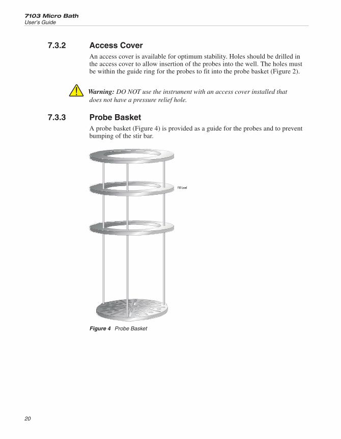
7.3.2 Access CoverAn access cover is available for optimum stability. Holes should be drilled inthe access cover to allow insertion of the probes into the well. The holes mustbe within the guide ring for the probes to fit into the probe basket (Figure 2).
Warning: DO NOT use the instrument with an access cover installed thatdoes not have a pressure relief hole.
7.3.3 Probe BasketA probe basket (Figure 4) is provided as a guide for the probes and to preventbumping of the stir bar.
7103 Micro Bath
User’s Guide
20
Fill Level
Figure 4 Probe Basket

7.3.4 Stir BarThe stir bar (Figure 5) sits in the bottom of the well for mixing the fluid provid-ing better accuracy, uniformity, and stability.
21
7
Parts and Controls
Figure 5 Stir Bar

8 General Operation
8.1 Changing Display UnitsThe 7103 can display temperature in Celsius or Fahrenheit. The temperatureunits are shipped from the factory set to Celsius. To change to Fahrenheit orback to Celsius there are two ways:
1. Press “SET” and “UP” simultaneously. The display units are changed.
or
1. Press the “SET” key three times from the temperature display to showUn= C
2. Press the “UP” or “DOWN” key to change units.
3. Press “SET” to store changes.
8.2 Switching to 230V OperationTo use 230 V, plug in the appropriate power cord into the unit. The “~” signshould always show in the PEM fuse window.
Note: Use 5 amp fuses for both 115 V and 230 V.
8.3 Bath FluidMany fluids work with the 7103 bath. Choosing a fluid requires considerationof many important characteristics of the fluid. Among these are temperaturerange, viscosity, specific heat, thermal conductivity, thermal expansion, electri-cal resistivity, fluid lifetime, safety, and cost. Hart Scientific recommends usingSilicone 200.05 Dow Oil. If the viscosity becomes to great, the stirrer may notfunction.
8.3.1 Temperature RangeOne of the most important characteristics to consider is the temperature rangeof the fluid. Few fluids work well throughout the complete temperature rangeof the bath. The temperature at which the bath is operated must always bewithin the safe and useful temperature range of the fluid. The lower tempera-ture range of the fluid is determined by the freeze point of the fluid or the tem-perature at which the viscosity becomes too great. The upper temperature isusually limited by vaporization, flammability, or chemical breakdown of thefluid. Vaporization of the fluid at higher temperatures may affect temperaturestability because of cool condensed fluid dripping into the bath from the lid.
23
8
General Operation

8.3.2 ViscosityViscosity is a measure of the thickness of a fluid, how easily it can be pouredand mixed. Viscosity affects the temperature stability of the bath. With low vis-cosity, fluid mixing is better which creates a more uniform temperaturethroughout the bath. This improves the bath response time which allows it tomaintain a more constant temperature. For good control the viscosity should beless than ten centistokes. Twenty centistokes is about the upper limit of allow-able viscosity. Viscosities greater than this cause very poor control stability andmay also overheat or damage the stirring motor. With oils viscosity may varygreatly with temperature.
When using fluids with higher viscosities the controller proportional band mayneed to be increased to compensate for the reduced response time. Otherwisethe temperature may begin to oscillate.
8.3.3 Specific HeatSpecific heat is the measure of the heat storage ability of the fluid. Specificheat, to a small degree, affects the control stability. It also affects the heatingand cooling rates. Generally, a lower specific heat means quicker heating andcooling. The proportional band may require some adjustment depending on thespecific heat of the fluid.
8.3.4 Thermal ConductivityThermal conductivity measures how easily heat flows through the fluid. Ther-mal conductivity of the fluid affects the control stability, temperature unifor-mity, and probe temperature settling time. Fluids with higher conductivitydistribute heat more quickly and evenly improving bath performance.
8.3.5 Thermal ExpansionThermal expansion describes how the volume of the fluid changes with temper-ature. Thermal expansion of the fluid used must be considered since the in-crease in fluid volume as the bath temperature changes may cause overflow.Excessive thermal expansion may also be undesirable in applications whereconstant liquid level is important. Many fluids including oils have significantthermal expansion.
8.3.6 Electrical ResistivityElectrical resistivity describes how well the fluid insulates against the flow ofelectric current. In some applications, such as measuring the resistance of baretemperature sensors, it may be important that little or no electrical leakage oc-cur through the fluid. In such conditions choose a fluid with very highresistivity.
7103 Micro Bath
User’s Guide
24

8.3.7 Fluid LifetimeMany fluids degrade over time because of evaporation, water absorption, gel-ling, or chemical breakdown. Often the degradation becomes significant nearthe upper temperature limit of the fluid, substantially reducing the fluid’slifetime.
8.3.8 SafetyWhen choosing a fluid always consider the safety issues associated. Obviouslywhere there are conditions of extreme hot or cold there can be danger to peopleand equipment. Fluids may also be hazardous for other reasons. Some fluidsmay be considered toxic. Contact with eyes, skin, or inhalation of vapors maycause injury. A proper fume hood must be used if hazardous or bothersome va-pors are produced.
Warning: Fluids at high temperatures may pose danger from BURNS,FIRE, and TOXIC FUMES. Use appropriate caution and safety equip-ment.
Fluids may be flammable and require special fire safety equipment and proce-dures. An important characteristic of the fluid to consider is the flash point. Theflash point is the temperature at which there is sufficient vapor given off so thatwhen there is sufficient oxygen present and a ignition source is applied the va-por will ignite. This does not necessarily mean that fire will be sustained at theflash point. The flash point may be either of the open cup or closed cup type.Either condition may occur in a bath situation. The closed cup temperature isalways the lower of the two. The closed cup represents the contained vapors in-side the tank and the open cup represents the vapors escaping the tank. Oxygenand an ignition source will be less available inside the tank.
Environmentally hazardous fluids require special disposal according to applica-ble federal or local laws after use.
8.3.9 CostCost of bath fluids may vary greatly, from cents per gallon for water to hun-dreds of dollars per gallon for synthetic oils. Cost may be an important consid-eration when choosing a fluid.
8.3.10 Commonly Used FluidsBelow is a description of some of the more commonly used fluids and theircharacteristics.
8.3.10.1 Water (Distilled)
Water is often used because of its very low cost, availability, and excellent tem-perature control characteristics. Water has very low viscosity and good thermalconductivity and heat capacity which makes it among the best fluids for control
25
8
General Operation

stability at low temperatures. Temperature stability is much poorer at highertemperatures because water condenses on the lid, cools and drips into the bath.Water is safe and relatively inert. The electrical conductivity of water may pre-vent its use in some applications. Water has a limited temperature range, from afew degrees above 0°C to a few degrees below 100°C. At higher temperaturesevaporation becomes significant. Water used in the bath should be distilled orsoftened to prevent mineral deposits. Consider using an algaecide chemical inthe water to prevent contamination.
8.3.10.2 Mineral Oil
Mineral oil or paraffin oil is often used at moderate temperatures above therange of water. Mineral oil is relatively inexpensive. At lower temperaturesmineral oil is quite viscous and control may be poor. At higher temperaturesvapor emission becomes significant. The vapors may be dangerous and use of afume hood is highly recommended. As with most oils mineral oil will expandas temperature increases so be careful not to fill the bath too full that it over-flows when heated. The viscosity and thermal characteristics of mineral oil ispoorer than water so temperature stability will not be as good. Mineral oil hasvery low electrical conductivity. Use caution with mineral oil since it is flam-mable and may also cause serious injury if inhaled or ingested.
8.3.10.3 Silicone Oil (Dow Corning 200.05, 200.10, 200.20)
Silicone oils are available which offer a much wider operating temperaturerange than mineral oil. Like most oils, silicone oils have temperature controlcharacteristics which are somewhat poorer than water. The viscosity changessignificantly with temperature and thermal expansion also occurs. These oilshave very high electrical resistivity. Silicone oils are fairly safe and non-toxic.Silicone oils are fairly expensive.
8.3.11 Fluid Characteristics ChartsTable 3 and Figure 6 on pages 27 and 28 have been created to provide help inselecting a heat exchange fluid media for your constant temperature bath.These charts provide both a visual and numerical representation of most of thephysical qualities important in making a selection. The list is not all inclusive.There may be other useful fluids not shown in this listing.
The charts include information on a variety of fluids which are often used asheat transfer fluid in baths. Because of the temperature range some fluids maynot be useful with your bath.
8.3.11.1 Limitations and Disclaimer
The information given in this manual regarding fluids is intended only to beused as a general guide in choosing a fluid. Though every effort has been madeto provide correct information we cannot guarantee accuracy of data or assuresuitability of a fluid for a particular application. Specifications may change andsources sometimes offer differing information. Hart Scientific cannot be liable
7103 Micro Bath
User’s Guide
26

for any personal injury or damage to equipment, product or facilities resultingfrom the use of these fluids. The user of the bath is responsible for collectingcorrect information, exercising proper judgment, and insuring safe operation.Operating near the limits of certain properties such as the flash point or viscos-ity can compromise safety or performance. Your company’s safety policies re-garding flash points, toxicity, and such issues must be considered. You areresponsible for reading the MSDS (material safety data sheets) and actingaccordingly.
27
8
General Operation
Fluid(# = Hart PartNo.)
LowerTemperatureLimit*
UpperTemperatureLimit*
FlashPoint
Viscosity(centistokes)
SpecificGravity
Specific Heat(cal/g/°C)
ThermalConductivity(cal/s/cm/°C)
ThermalExpansion(cm/cm/°C)
Resistivity(10
12-cm )
Halocarbon 0.8#5019
–90°C (v)** 70°C (e) NONE 5.7 @ –50°C0.8 @ 40°C0.5 @ 70°C
1.71 @ 40°C 0.2 0.0004 0.0011
Methanol –96°C (fr) 60°C (b) 54°C 1.3 @ –35°C0.66 @ 0°C0.45 @ 20°C
0.810 @ 0°C0.792 @ 20°C
0.6 0.0005 @ 20°C 0.0014 @ 25°C
Water 0°C (fr) 95°C (b) NONE 1 @ 25°C0.4 @ 75°C
1.00 1.00 0.0014 0.0002 @ 25°C
EthyleneGlycol—50%#5020
–35°C (fr) 110°C (b) NONE 7 @ 0°C2 @ 50°C0.7 @ 100°C
1.05 0.8 @ 0°C 0.001
Mineral Oil 40°C (v) 190°C (fl) 190°C 15 @ 75°C5 @ 125°C
0.87 @ 25°C0.84 @ 75°C0.81 @ 125°C
0.48 @ 25°C0.53 @ 75°C0.57 @ 125°C
0.00025 @ 25°C 0.0007 @ 50°C 5 @ 25°C
Dow Corning200.05Silicone Oil
–40°C (v)** 133°C (fl, cc) 133°C 5 @ 25°C 0.92 @ 25°C 0.4 0.00028 @ 25°C 0.00105 1000 @ 25°C10 @ 150°C
Dow Corning200.10#5012
–35°C (v)** 165°C (fl, cc) 165°C 10 @ 25°C3 @ 135°C
0.934 @ 25°C 0.43 @ 40°C0.45 @ 100°C0.482 @ 200°C
0.00032 @ 25°C 0.00108 1000 @ 25°C50 @ 150°C
Dow Corning200.20#5013
7°C (v) 230°C (fl, cc) 230°C 20 @ 25°C 0.949 @ 25°C 0.370 @ 40°C0.393 @ 100°C0.420 @ 200°C
0.00034 @ 25°C 0.00107 1000 @ 25°C50 @ 150°C
Dow Corning200.50Silicone Oil
25°C (v) 280°C (fl, cc) 280°C 50 @ 25°C 0.96 @ 25°C 0.4 0.00037 @ 25°C 0.00104 1000 @ 25°C50 @ 150°C
Dow Corning 550#5016
70°C (v) 232°C (fl, cc)300°C (fl, oc)
232°C 50 @ 70°C10 @ 104°C
1.07 @ 25°C 0.358 @ 40°C0.386 @ 100°C0.433 @ 200°C
0.00035 @ 25°C 0.00075 100 @ 25°C1 @ 150°C
Dow Corning 710
#5017
80°C (v) 302°C (fl, oc) 302°C 50 @ 80°C7 @ 204°C
1.11 @ 25°C 0.363 @ 40°C0.454 @ 100°C0.505 @ 200°C
0.00035 @ 25°C 0.00077 100 @ 25°C1 @ 150°C
Dow Corning210-HSilicone Oil
66°C (v) 315°C (fl, oc) 315°C 50 @ 66°C14 @ 204°C
0.96 @ 25°C 0.34 @ 100°C 0.0003 0.00095 100 @ 25°C1 @ 150°C
Heat TransferSalt#5001
145°C (fr) 530°C NONE 34 @ 150°C6.5 @ 300°C2.4 @ 500°C
2.0 @ 150°C1.9 @ 300°C1.7 @ 500°C
0.33 0.0014 0.00041 1.7 Ω /cm3
*Limiting Factors — b - boiling point e - high evaporation fl - flash point fr - freeze point v - viscosity — Flash point test oc = open cup cc = closed cup**Very low water solubility, ice will form as a slush from condensation below freezing.
Table 3 Table of Various Bath Fluids

8.3.11.2 About the Graph
The fluid graph visually illustrates some of the important qualities of the fluidsshown.
Temperature Range: The temperature scale is shown in degrees Celsius. Thefluids’ general range of application is indicated by the shaded bands. Qualitiesincluding pour point, freeze point, important viscosity points, flash point, boil-ing point and others may be shown.
7103 Micro Bath
User’s Guide
28
–100°C 0°C 100°C 200°C 300°C 400°C 500°C 600°C
BP - Boiling PointCS - CentistokesEP - Evaporation Point(fluid loss
due to evaporation)FL - Flash PointFR - Freeze PointPP - Pour Point
Shaded area represents usable range of fluid starting at50 centistokes. Lighter shading represents decreasingviscosity, while vaporization and decomposition increase.
Black area represents liquid range with excessiveviscosity.
Range over which a fume hood is recommended.
10 CS FL 302°CPPSilicone Oil5017
Silicone Oil5014 10 CS FL 280°CPP
Silicone Oil5013 10 CS FL 232°CPP
Silicone Oil5012 10 CS FL 211°CPP
Silicone Oil5010 10 CS FL 133°CPP
EP 100°CHFE 75005023
10 CS EPHalocarbon5019
FL 177°CMineral Oil5011
BPWater FR
BPMethanol FR (Pure)
10 CS BPEthylene Glycol(50/50 with H O)
50202 FR
Decomposition Starts
Bath Salt5001
FR
10 CS
FL 12°C
Ethanol FL 16°C
10 CS FL 60°CDynalene HF/LO5022
10 CS
10 CS
Legend
Figure 6 Chart of Various Bath Fluids

Freezing Point: The freezing point of a fluid is an obvious limitation to stir-ring. As the freezing point is approached high viscosity may also limitperformance.
Pour Point: This represents a handling limit for the fluid.
Viscosity: Points shown are at 50 and 10 centistokes viscosity. When viscosityis greater than 50 centistokes stirring is very poor and the fluid is unsatisfactoryfor bath applications. Optimum stirring generally occurs at 10 centistokes andbelow.
Fume Point: A fume hood should be used. This point is very subjective in na-ture and is impacted by individual tolerance to different fumes and smells, howwell the bath is covered, the surface area of the fluid in the bath, the size andventilation of the facility where the bath is located and other conditions. We as-sume the bath is well covered at this point. This is also subject to companypolicy.
Flash Point: The point at which ignition may occur. The point shown may beeither the open or closed cup flash point. Refer to the flash point discussion inSection8.3.8.
Boiling Point: At or near the boiling point of the fluid, the temperature stabil-ity is difficult to maintain. Fuming or evaporation is excessive. Large amountsof heater power may be required because of the heat of vaporization.
Decomposition: The temperature may reach a point at which decomposition ofthe fluid begins. Further increasing the temperature may accelerate decomposi-tion to the point of danger or impracticality.
8.4 StirringStirring of the bath fluid is very important for stable temperature control. Thefluid must be mixed well for good temperature uniformity and fast controllerresponse. The stirrer is adjusted for optimum performance. Table 4 on page 30shows nominal stirrer motor settings for several fluids.
If the stirrer does not function properly, the instrument will oscillate and notmeet published specifications.
NOTE: If the bath is used with the probe basket removed, stir motor set-tings need to be changed so that a small vortex can be seen in the liquid.
29
8
General Operation

WARNING: Do not mix water and oil when exceeding temperatures of90°C
8.5 PowerPower to the bath is provided by an AC mains supply and passes through a fil-ter to prevent switching spikes from being transmitted to other equipment. Re-fer to Section 3.1, Specifications, for power details.
To turn on the bath, switch the control panel power switch to the ON position.The stir motor will turn on, the LED display will begin to show the bath tem-perature, and the heater will turn on or off until the bath temperature reachesthe programmed set-point.
When powered on the control panel display will briefly show a four digit num-ber. This number indicates the number of times power has been applied to thebath. Also briefly displayed is data which indicates the controller hardwareconfiguration and version number. This data is used in some circumstances fordiagnostic purposes.
8.6 Thermal Electric Devices (TED)The power to the bath is precisely controlled by the temperature controller tomaintain a constant bath temperature. Power is controlled by periodicallyswitching the TEDs on for a certain amount of time using power transistors.
8.7 Fluid DrainThe fluid may be drained from the 7103 by tightly screwing the transport/pouraccess lid onto the top of the bath and pouring the liquid into an appropriatecontainer.
8.8 Temperature ControllerThe bath temperature is controlled by Hart Scientific’s unique hybrid digi-tal/analog temperature controller. The controller offers the tight control stability
7103 Micro Bath
User’s Guide
30
Liquid Stir Motor Setting Temperature Range
Distilled Water 12 5°C to 90°C(41°F to 194°F)
Ethylene Glycol 12 –5°C to 90°C(25°F to 194°F)
200.05 Oil 15 –30°C to 125°C(–22°F to 257°F)
200.10 Oil 15 25°C to 125°C(77°F to 257°F)
Table 4 Nominal Stirrer Motor Settings With Different Liquids

of an analog temperature controller as well as the flexibility and programmabil-ity of a digital controller.
The bath temperature is monitored with a platinum resistance sensor in the con-trol probe. The signal is electronically compared with the programmable refer-ence signal, amplified, and then fed to a pulse-width modulator circuit whichcontrols the amount of power applied to the bath heater.
The bath is operable within the temperature range given in the specifications.For protection against solid-state relay failure or other circuit failure, a bi-me-tallic cut-out automatically turns off the heater anytime the bath temperatureexceeds the maximum temperature.
The controller allows the operator to set the bath temperature with high resolu-tion, adjust the proportional band, monitor the heater output power, and pro-gram the controller configuration and calibration parameters. The controllermay be operated in temperature units of degrees Celsius or Fahrenheit. Thecontroller is operated and programmed from the front control panel using thefour key switches and digital LED display. The controller is equipped with aserial RS-232 digital interface for remote operation. Operation using the digitalinterfaces is discussed in Section 10, Digital Communications.
When the controller is set to a new set-point the bath heats or cools to the newtemperature. Once the new temperature is reached the bath usually takes 15–20minutes for the temperature to settle and stabilize. There may be a small over-shoot or undershoot.
31
8
General Operation

9 Controller Operation
This chapter discusses in detail how to operate the bath temperature controllerusing the front control panel. Using the front panel key-switches and LED dis-play the user may monitor the well temperature, set the temperature set-point indegrees C or F, monitor the heater output power, adjust the controller propor-tional band, and program the calibration parameters, operating parameters, andserial interface configuration. Operation of the functions and parameters areshown in the flowchart in Figure 7 on page 34. This chart may be copied forreference.
In the following discussion a button with the word SET, UP, EXIT or DOWNinside indicates the panel button while the dotted box indicates the displayreading. Explanation of the button or display reading are to the right of eachbutton or display value.
9.1 Well TemperatureThe digital LED display on the front panel allows direct viewing of the actualwell temperature. This temperature value is what is normally shown on the dis-play. The units, C or F, of the temperature value are displayed at the right. Forexample,
100.00C Well temperature in degrees Celsius
The temperature display function may be accessed from any other function bypressing the “EXIT” button.
9.2 Temperature Set-pointThe temperature set-point can be set to any value within the range and resolu-tion as given in the specifications. Be careful not to exceed the safe upper tem-perature limit of any device inserted into the well.
Setting the temperature involves two steps: (1) select the set-point memory and(2) adjust the set-point value.
9.2.1 Programmable Set-pointsThe controller stores 8 set-point temperatures in memory. The set-points can bequickly recalled to conveniently set the calibrator to a previously programmedtemperature set-point.
To set the temperature one must first select the set-point memory. This functionis accessed from the temperature display function by pressing “SET”. Thenumber of the set-point memory currently being used is shown at the left on thedisplay followed by the current set-point value.
33
9
Controller Operation

7103 Micro Bath
User’s Guide
34
UP UP
DOWN DOWN
SET
OperatingParameters
Menu
SET
SET
CalMenu
ALPHA
Adj. R0
DO
NO
T C
HA
NG
ET
HE
SE
VA
LUE
S.S
EE
MA
NU
AL
DO
NO
T C
HA
NG
ET
HE
SE
VA
LUE
S.S
EE
MA
NU
AL
SerialInterface
Menu
BAUDRate
AdjustBAUD Rate
SamplePeriod
Adj. SamplePeriod
DELTA
DuplexMode
Adj. DuplexMode
Linefeed
BETA
AdjustLinefeed
AdjustBETA
EXITEXIT
EXIT
EXIT
EXIT
UP
DOWN
DOWN
SET
SET
SET
UP
+
+
+
Display Power
Toggles °C / °F
SET
SET
Select Setpoint
Adjust Setpoint
Units °C/°F
Scan On/Off
Scan Rate
DisplayTemperature
Configuration Menu
Secondary Functions
X5
StirSpeed
HL
Adj. StirSpeed
Adj.HL
Display of Rs
Switch Hold Display Mode
EXIT
Set Proportional Band
R0
HardCut-out
Adj. HardCut-out
Adj. ALPHA
Adj. DELTA
Menu Legend:
Press “SET” to step through themenu and to store the parametervalue.
Press “EXIT” briefly to skip aparameter without storing theparameter value.
Hold “EXIT” to exit the menu and
Figure 7 Controller Operation Flowchart

100.00C Well temperature in degrees Celsius
S Access set-point memory
1. 25 Set-point memory 1, 25°C currently used
To change the set-point memory press “UP” or “DOWN”.
4. 125. New set-point memory 4, 125°C
Press “SET” to accept the new selection and access the set-point value.
S Accept selected set-point memory
9.2.2 Set-point ValueThe set-point value may be adjusted after selecting the set-point memory and
pressing “SET”.
4 125. Set-point 4 value in°C
If the set-point value is correct, hold “EXIT” to resume displaying the welltemperature. Press “UP” or “DOWN” to adjust the set-point value.
125.00 New set-point value
When the desired set-point value is reached press “SET” to accept the newvalue and access the temperature scale units selection. If “EXIT” is pressed in-stead of “SET”, any changes made to the set-point are ignored.
S Accept new set-point value
9.2.3 Temperature Scale UnitsThe temperature scale units of the controller can be set by the user to degreesCelsius (°C) or Fahrenheit (°F). The selected units are used in displaying thewell temperature, set-point, and proportional band.
Press “SET” after adjusting the set-point value to change display units.
Un= C Scale units currently selected
Press “UP” or “DOWN” to change the units.
35
9
Controller Operation

Un= F New units selected
9.3 ScanThe scan rate can be set and enabled so that when the set-point is changed thebath heats or cools at a specified rate (degrees per minute) until it reaches thenew set-point. With the scan disabled the bath heats or cools at the maximumpossible rate.
9.3.1 Scan ControlThe scan is controlled with the scan on/off function that appears in the mainmenu after the set-point function.
Sc=OFF Scan function off
Press “UP” or “DOWN” to toggle the scan on or off.
Sc=On Scan function on
Press “SET” to accept the present setting and continue.
S Accept scan setting
9.3.2 Scan RateThe next function in the main menu is the scan rate. The scan rate can be setfrom .1 to 99.9°C/min. The maximum scan rate however is actually limited bythe natural heating or cooling rate of the instrument. This is often less than100°C/min, especially when cooling.
The scan rate function appears in the main menu after the scan control function.The scan rate units are in degrees per minute, degrees C or F depending on theselected units.
Sr= 10.0 Scan rate in°C/min
Press “UP” or “DOWN” to change the scan rate.
Sr= 2.0 New scan rate
Press “SET” to accept the new scan rate and continue.
S Accept scan rate
7103 Micro Bath
User’s Guide
36

9.4 Temperature Display HoldThe 7103 has a display hold function which allows action of an external switchto freeze the displayed temperature and stop the set-point from scanning. Thisis useful for testing thermal switches and cut-outs. The instrument must bepowered off before attaching thermal switches or cut-outs. This section ex-plains the functions available for operating the temperature hold feature. An ex-ample follows showing how to set up and use the hold feature to test a switch.
9.4.1 Hold Temperature DisplayThe hold feature is enabled by simply pressing the “UP” button when the tem-perature is displayed. The hold temperature display shows the hold temperatureon the right and the switch status on the left. For the status “c” means theswitch is closed and “o” means the switch is open. The status flashes when theswitch is in its active position (opposite the normal position). The hold temper-ature shows what the temperature of the well was when the switch changedfrom its normal position to its active position. While the switch is in the normalposition the hold temperature will follow the well temperature.
If the Scan Control is “OFF” and the Hold Temperature Display is being used,the temperature at which the switch is activated does not affect the set-pointtemperature. However, if the Scan Control is “ON” and the Hold TemperatureDisplay is being used, the temperature at which the switch is activated is storedas the new set-point temperature.
Operation of the hold temperature display is outlined below.
143.50C Well temperature display
U Access hold display
c 144.8 Switch status and hold temperature
To return to the normal well temperature display press “DOWN”.
9.4.2 Mode SettingThe Hold Function is always in the automatic mode. In this mode the normalposition is set to whatever the switch position is when the set-point is changed.For example, if the switch is currently open when the set-point is changed, theclosed position then becomes the new active position. The normal position willbe set automatically under any of the following conditions, (1) a new set-pointnumber is selected, (2) the set-point value is changed, (3) a new set-point is setthrough the communications channels.
37
9
Controller Operation

9.4.3 Switch WiringThe thermal switch or cut-out is wired to the calibrator at the two terminals onthe back of the Micro-Bath labeled “DISPLAY HOLD”. The switch wires maybe connected to the terminals either way. Internally the black terminal connectsto ground. The red terminal connects to +5V through a 100 kΩ resistor. Thecalibrator measures the voltage at the red terminal and interprets +5V as openand 0V as closed.
9.4.4 Switch Test ExampleThis section describes a possible application for the temperature hold featureand how the instrument is set up and operated.
Suppose you have a thermal switch which is supposed to open at about 75°Cand close at about 50°C and you want to test the switch to see how accurate andrepeatable it is. You can use the temperature hold feature and the scan functionto test the switch. Measurements can be made by observing the display or, pref-erably, by collecting data using a computer connected to the RS-232 port. Toset up the test do the following steps.
1. Connect the switch wires to the terminals on the back of the Micro-Bath andplace the switch in the well.
2. Enable set-point scanning by setting the scan to “ON” in the primary menu(see section9.3.1).
3. Set the scan rate to a low value, say 1.0°C/min. (see Section 9.3.2). If thescan rate is too high you may lose accuracy because of transient temperaturegradients. If the scan rate is too low the duration of the test may be longer thanis necessary. You may need to experiment to find the best scan rate.
4. Set the first program set-point to a value above the expected upper switchtemperature, say 90°C.
5. Set the second program set-point to a value below the expected lower switchtemperature, say 40°C, in the program menu.
6. Collect data on a computer connected to the RS-232 port. Refer to Section9.8.2, Serial Interface Parameters, for instructions on configuring the RS-232communications interface.
9.5 Secondary MenuFunctions which are used less often are accessed within the secondary menu.The secondary menu is accessed by pressing “SET” and “EXIT” simulta-neously and then releasing. The first function in the secondary menu is theheater power display. (See Figure 7 on page 34.)
7103 Micro Bath
User’s Guide
38

9.6 Thermal Electric Device (TED)The temperature controller controls the temperature of the well by pulsing theTED on and off. The total power being applied to the TED is determined by theduty cycle or the ratio of TED on time to the pulse cycle time. By knowing theamount of heating the user can tell if the calibrator is heating up to theset-point, cooling down, or controlling at a constant temperature. Monitoringthe percent heater power will let the user know how stable the well temperatureis. With good control stability the percent heating power should not fluctuatemore than ±5% within one minute.
The heater power display is accessed in the secondary menu. Press “SET” and“EXIT” simultaneously and release. The heater power will be displayed as apercentage of full power.
100.00C Well temperature
S+E Access heater power in secondary menu
SEC Flashes
12.0 P Heater power in percent
To exit out of the secondary menu hold “EXIT”. To continue on to the propor-tional band setting function press “EXIT” momentarily or “SET”.
9.7 Proportional BandIn a proportional controller such as this the heater output power is proportionalto the well temperature over a limited range of temperatures around theset-point. This range of temperature is called the proportional band. At the bot-tom of the proportional band the heater output is 100%. At the top of the pro-portional band the heater output is 0. Thus as the temperature rises the heaterpower is reduced, which consequently tends to lower the temperature backdown. In this way the temperature is maintained at a fairly constanttemperature.
The temperature stability of the well and response time depend on the width ofthe proportional band. If the band is too wide the well temperature will deviateexcessively from the set-point due to varying external conditions. This is be-cause the power output changes very little with temperature and the controllercannot respond very well to changing conditions or noise in the system. If theproportional band is too narrow the temperature may swing back and forth be-cause the controller overreacts to temperature variations. For best control stabil-ity the proportional band must be set for the optimum width.
39
9
Controller Operation

The proportional band width is set at the factory to about 5.0°C. The propor-tional band width may be altered by the user if he desires to optimize the con-trol characteristics for a particular application.
The proportional band width is easily adjusted from the front panel. The widthmay be set to discrete values in degrees C or F depending on the selected units.The proportional band adjustment is be accessed within the secondary menu.Press “SET” and “EXIT” to enter the secondary menu and show the heaterpower. Then press “SET” to access the proportional band.
S+E Access heater power in secondary menu
12.0 P Heater power in percent
S Access proportional band
ProP Flashes “ProP” and the setting
5.0 Proportional band setting
To change the proportional band press “UP” or “DOWN”.
4.0 New proportional band setting
To store the new setting press “SET”. Press “EXIT” to continue without storingthe new value.
S Accept the new proportional band setting
9.8 Controller ConfigurationThe controller has a number of configuration and operating options and calibra-tion parameters which are programmable via the front panel. These are ac-cessed from the secondary menu after the proportional band function bypressing “SET”. Pressing “SET” again enters the first of three sets of configu-ration parameters: operating parameters, serial interface parameters, and cali-bration parameters. The menus are selected using the “UP” and “DOWN” keysand then pressing “SET”. (See Figure 7 on page 34.)
9.8.1 Operating ParametersThe operating parameters menu is indicated by,
PAr Operating parameters menu
7103 Micro Bath
User’s Guide
40

The operating parameters menu contains the High Limit and Stir Speedparameters.
9.8.1.1 High Limit
The High Limit Parameter adjusts the upper set-point temperature. The factorydefault and maximum temperature are set to 126°C. For safety, a user can ad-just the HL down so the maximum temperature set-point is restricted.
HL High Limit parameter
Press “SET” to enable adjustment of HL
HL Flashes “HL” and then displays the setting
H=126 Current HL setting
Adjust the HL parameter using “UP” or “DOWN”
H=90 New HL setting
Press “SET” to accept the new temperature limit.
9.8.1.2 Stir Speed
The Stir Speed parameter adjusts stirrer motor speed. The factory default is 15.
Str SP Flashes “Str Sp” and then displays the setting
0 Current Stir Speed setting
To change the stir speed press “UP” or “DOWN”.
16 New Stir Speed setting
Press “SET” to accept the new Stir Speed.
The stir motor speed needs to be varied for best stability. Table 4 on page 30shows nominal settings for several fluids.
9.8.2 Serial Interface ParametersThe serial RS-232 interface parameters menu is indicated by,
SErIAL Serial RS-232 interface parameters menu
41
9
Controller Operation

The serial interface parameters menu contains parameters which determine theoperation of the serial interface. These controls only apply to instruments fittedwith the serial interface. The parameters in the menu are — BAUD rate, sampleperiod, duplex mode, and linefeed. Press “UP” to enter the menu.
9.8.2.1 Baud Rate
The baud rate is the first parameter in the menu. The baud rate setting deter-mines the serial communications transmission rate.
The baud rate parameter is indicated by,
bAUd Flashes “bAUd” and then displays the stetting
2400 b Current baud rate
The baud rate of the serial communications may be programmed to 300, 600,1200, 2400, 4800, or 9600 baud. Use “UP” or “DOWN” to change the baudrate value.
4800 b New baud rate
Press “SET” to set the baud rate to the new value or “EXIT” to abort the opera-tion and skip to the next parameter in the menu.
9.8.2.2 Sample Period
The sample period is the next parameter in the serial interface parameter menu.The sample period is the time period in seconds between temperature measure-ments transmitted from the serial interface. If the sample rate is set to 5, the in-strument transmits the current measurement over the serial interfaceapproximately every five seconds. The automatic sampling is disabled with asample period of 0. The sample period is indicated by,
SPer Flashes “SPEr” and then displays the setting
SP= 1 Current sample period (seconds)
Adjust the value with “UP” or “DOWN” and then use “SET” to store the sam-ple rate to the displayed value. “EXIT” does not store the new value.
SP= 60 New sample period
9.8.2.3 Duplex Mode
The next parameter is the duplex mode. The duplex mode may be set to full du-plex or half duplex. With full duplex any commands received by the calibrator
7103 Micro Bath
User’s Guide
42

via the serial interface will be immediately echoed or transmitted back to thedevice of origin. With half duplex the commands will be executed but not ech-oed. The duplex mode parameter is indicated by,
dUPL Flashes “dUPL” and then displays the setting
d=FULL Current duplex mode setting
The mode may be changed using “UP” or “DOWN” and pressing “SET”.
d=HALF New duplex mode setting
9.8.2.4 Linefeed
The final parameter in the serial interface menu is the linefeed mode. This pa-rameter enables (on) or disables (off) transmission of a linefeed character (LF,ASCII 10) after transmission of any carriage-return. The linefeed parameter isindicated by,
LF Flashes “LF” and then displays the setting
LF= On Current linefeed setting
The mode may be changed using “UP” or “DOWN” and pressing “SET”.
LF= OFF New linefeed setting
9.8.3 Calibration ParametersThe operator of the Micro-Bath controller has access to the Hard Cut-out and anumber of the bath calibration constants namely R0, ALPHA, DELTA, andBETA. These values are set at the factory and should not be altered. The cor-rect values are important to the accuracy and proper and safe operation of thebath. Access to these parameters is available to the user only so that in theevent that the controller memory fails the user may restore these values to thefactory settings. The user should have a list of these constants and their settingswith manual.
Caution: DO NOT change the values of the bath calibration constantsfrom the factory set values. The correct setting of these parameters is im-portant to the safety and proper operation of the bath.
The calibration parameters menu is indicated by:
43
9
Controller Operation
CAL Calibration parameters menu
Press “SET” five times to enter the menu.
The calibration parameters R0, ALPHA, DELTA, and BETA characterize theresistance-temperature relationship of the platinum control sensor. These pa-rameters may be adjusted by an experienced user to improve the accuracy ofthe calibrator.
9.8.3.1 Hard Cutout
This parameter is the temperature above which the unit shuts down automati-cally. The parameter is set at the factory to approximately 140°C and can bechanged only through the variable resistor. This parameter cannot be changedthrough the instrument menu or the communications port.
9.8.3.2 R0
This probe parameter refers to the resistance of the control probe at 0°C. Thevalue of this parameter is set at the factory for best instrument accuracy.
9.8.3.3 ALPHA
This probe parameter refers to the average sensitivity of the probe between 0and 100°C. The value of this parameter is set at the factory for best instrumentaccuracy.
9.8.3.4 DELTA
This probe parameter characterizes the curvature of the resistance-temperaturerelationship of the sensor. The value of this parameter is set at the factory forbest instrument accuracy.
9.8.3.5 BETA
This probe parameter characterizes the low temperatures. The value of this pa-rameter is set at the factory for best instrument accuracy.
7103 Micro Bath
User’s Guide
44

10 Digital Communication Interface
The Micro-Bath calibrator is capable of communicating with and being con-trolled by other equipment through the digital serial interface.
With a digital interface the instrument may be connected to a computer or otherequipment. This allows the user to set the set-point temperature, monitor thetemperature, and access any of the other controller functions, all using remotecommunications equipment. Communications commands are summarized inTable 5 on page 48.
10.1 Serial CommunicationsThe calibrator is installed with an RS-232 serial interface that allows serial dig-ital communications over fairly long distances. With the serial interface the usermay access any of the functions, parameters and settings discussed in Section9with the exception of the baud rate setting.
10.1.1 WiringThe serial communications cableattaches to the calibrator throughthe DB-9 connector at the back ofthe instrument. Figure 8 shows thepin-out of this connector and sug-gested cable wiring. To eliminatenoise the serial cable should beshielded with low resistance be-tween the connector (DB-9) andthe shield. If the unit is used in aheavy industrial setting, the serialcable must be limited to ONE ME-TER in length.
10.1.2 SetupBefore operation the serial inter-face must first be set up by pro-gramming the BAUD rate andother configuration parameters.These parameters are programmedwithin the serial interface menu.The serial interface parametersmenu is outlined in Figure 7 onpage 34.
To enter the serial parameter pro-gramming mode first press “EXIT”while pressing “SET” and release to enter the secondary menu. Press “SET” re-
45
10
Digital Communication Interface
Figure 8 Serial Cable Wiring

peatedly until the display reads “PAr”. Press “UP” until the serial interfacemenu is indicated with“SErIAL”. Finally press “SET” to enter the serial pa-rameter menu. In the serial interface parameters menu are the BAUD rate, thesample rate, the duplex mode, and the linefeed parameter.
10.1.2.1 Baud Rate
The baud rate is the first parameter in the menu. The display will prompt withthe baud rate parameter by showing “bAUd”. Press “SET” to choose to set theBAUD rate. The current baud rate value will then be displayed. The baud rateof the 7103 serial communications may be programmed to 300, 600, 1200,2400, 4800, or 9600 baud. The baud rate is pre-programmed to 2400 baud. Use“UP” or “DOWN” to change the baud rate value. Press “SET” to set the baudrate to the new value or “EXIT” to abort the operation and skip to the next pa-rameter in the menu.
10.1.2.2 Sample Period
The sample period is the next parameter in the menu and prompted with“SPEr”. The sample period is the time period in seconds between temperaturemeasurements transmitted from the serial interface. If the sample rate is set to5, the instrument transmits the current measurement over the serial interface ap-proximately every five seconds. The automatic sampling is disabled with asample period of 0. Press “SET” to choose to set the sample period. Adjust theperiod with “UP” or “DOWN” and then use “SET” to set the sample rate to thedisplayed value.
10.1.2.3 Duplex Mode
The next parameter is the duplex mode indicated with “dUPL”. The duplexmode may be set to half duplex (“HALF”) or full duplex (“FULL”). With fullduplex any commands received by the thermometer via the serial interface willbe immediately echoed or transmitted back to the device of origin. With halfduplex the commands will be executed but not echoed. The default setting isfull duplex. The mode may be changed using “UP” or “DOWN” and pressing“SET”.
10.1.2.4 Linefeed
The final parameter in the serial interface menu is the linefeed mode. This pa-rameter enables (“On”) or disables (“OFF”) transmission of a linefeed charac-ter (LF, ASCII 10) after transmission of any carriage-return. The default settingis with linefeed on. The mode may be changed using “UP” or “DOWN” andpressing “SET”.
10.1.3 Serial OperationOnce the cable has been attached and the interface set up properly the control-ler will immediately begin transmitting temperature readings at the pro-grammed rate. The serial communications uses 8 data bits, one stop bit, and no
7103 Micro Bath
User’s Guide
46

parity. The set-point and other commands may be sent via the serial interface toset the temperature set-point and view or program the various parameters. Theinterface commands are discussed in Section10.2. All commands are ASCIIcharacter strings terminated with a carriage-return character (CR, ASCII 13).
10.2 Interface CommandsThe various commands for accessing the calibrator functions via the digital in-terfaces are listed in this section (see Table 5). These commands are used withthe RS-232 serial interface. The commands are terminated with a carriage-re-turn character. The interface makes no distinction between upper and lowercase letters, hence either may be used. Commands may be abbreviated to theminimum number of letters which determines a unique command. A commandmay be used to either set a parameter or display a parameter depending onwhether or not a value is sent with the command following a “=” character. Forexample “s”<CR> will return the current set-point and “s=150.0”<CR> will setthe set-point to 150.0 degrees.
In the following list of commands, characters or data within brackets, “[” and“]”, are optional for the command. A slash, “/”, denotes alternate characters ordata. Numeric data, denoted by “n”, may be entered in decimal or exponentialnotation. Characters are shown in lower case although upper case may be used.Spaces may be added within command strings and will simply be ignored.Backspace (BS, ASCII 8) may be used to erase the previous character. A termi-nating CR is implied with all commands.
47
10
Digital Communication Interface

7103 Micro Bath
User’s Guide
48
Command DescriptionCommandFormat
CommandExample Returned
ReturnedExample
AcceptableValues
Display Temperature
Read current set-point s[etpoint] s set: 999.99 {C or F} set: 150.00 C
Set current set-point to n s[etpoint]=n s=200.00 InstrumentRange
Read temperature t[emperature] t t: 999.99 {C or F} t: 55.6 C
Read temperature units u[nits] u u: x u: C
Set temperature units: u[nits]=c/f C or F
Set temperature units to Celsius u[nits]=c u=c
Set temperature units toFahrenheit
u[nits]=f u=f
Read scan mode sc[an] sc scan: {ON or OFF} scan:ON
Set scan mode sc[an]=on/off sc=on ON or OFF
Read scan rate sr[ate] sr srat: 99.9 {C or F}/min srat:12.4C/min
Set scan rate sr[ate]=n sr=1.1 .1 to 99.9
Read hold ho[ld] ho hold: open/closed, 99.9{C or F}
hold: open, 30.5C
Secondary Menu
Read proportional band setting pr[opband] pr pb: 999.9 pb: 15.9
Set proportional band to n pr[opband]=n pr=8.83 Depends onConfiguration
Read heater power(duty cycle)
po[wer] po po: 999.9 po: 1.0
Configuration Menu
Operating Parameters Menu
Read stirrer motor speed mo[tor] mo mo: 99 mo: 15
Set stirrer motor speed to n mo[tor]=n mo=16 0 to 40
Read high limit hl hl hl:999 hl:126
Set high limit hl=n hl=90 0–126
Serial Interface Menu
Read serial sample setting sa[mple] sa sa: 9 sa: 1
Set serial sampling setting to nseconds
sa[mple]=n sa=0 0 to 999
Set serial duplex mode: du[plex]=f[ull]/h[alf] FULL or HALF
Set serial duplex mode to full du[plex]=f[ull] du=f
Set serial duplex mode to half du[plex]=h[alf] du=h
Set serial linefeed mode: lf[eed]=on/of[f] ON or OFF
Set serial linefeed mode to on lf[eed]=on lf=on
Set serial linefeed mode to off lf[eed]=of[f] lf=of
Calibration Menu
Read R0 calibration parameter r[0] r r0: 999.999 r0: 100.578
Set R0 calibration parameter to n r[0]=n r=100.324 90 to 110
Table 5 Controller Communications Commands

49
10
Digital Communication Interface
Command DescriptionCommandFormat
CommandExample Returned
ReturnedExample
AcceptableValues
Read ALPHA calibrationparameter
al[pha] al al: 9.9999999 al: 0.0038573
Set ALPHA calibration parameterto n
al[pha]=n al=0.0038433 .002 to .005
Read DELTA calibrationparameter
de[lta] de de:9.99999 de: 1.507
Set DELTA calibration parameter de[lta]=n de=1.3742 0–3.0
Read BETA calibration parameter be[ta] be be:99.999 be:03427
Set BETA calibration parameter be[ta]=n be=0.342 –20 to 20
Functions not on menu
Read firmware version number *ver[sion] *ver ver.9999,9.99 ver.7103,2.00
Read structure of all commands h[elp] h list of commands
Read all operating parameters all all list of parameters
Legend: [] Optional Command data
{} Returns either information
n Numeric data supplied by user
9 Numeric data returned to user
x Character data returned to user
Note: When DUPLEX is set to FULL and a command is sent to READ, the command is returned followed by acarriage return and linefeed. Then the value is returned as indicated in the RETURNED column.
Controller Communications Commands continued

11 Test Probe Calibration
For optimum accuracy and stability, allow the calibrator to warm up for 25minutes after power-up and then allow adequate stabilization time after reach-ing the set-point temperature. After completing operation of the calibrator, al-low the well to cool by setting the temperature to 25°C for one-half hour beforeswitching the power off.
11.1 Calibrating a Single ProbeInsert the probe to be calibrated into the well of the bath. Best results are ob-tained with the probe inserted to the full depth of the well. Once the probe is in-serted into the well, allow adequate stabilization time to allow the test probetemperature to settle as described above. Once the probe has settled to the tem-perature of the well, it may be compared to the calibrator display temperature.The display temperature should be stable to within 0.1°C degree for bestresults.
Caution: Never introduce any foreign material into the well.
11.2 Stabilization and AccuracyThe stabilization time of the Micro-Bath depends on the conditions and temper-atures involved. Typically the test well will be stable to 0.1°C within 10 min-utes of reaching the set-point temperature. Ultimate stability will be achieved30 minutes after reaching the set temperature.
Inserting a cold probe into a well requires another period of stabilizing depend-ing on the magnitude of the disturbance and the required accuracy. For exam-ple, inserting a .25 inch diameter room temperature probe at 125°C takes 5minutes to be within 0.1°C of its settled point and takes 10 minutes to achievemaximum stability.
Speeding up the calibration process can be accomplished by knowing how soonto make the measurement. Typical measurements should be made at the desiredtemperatures with the desired test probes to establish these times.
51
11
Test Probe Calibration

12 Calibration Procedure
Sometimes the user may want to calibrate the bath to improve the temperatureset-point accuracy. Calibration is done by adjusting the controller probe calibra-tion constants R0 , ALPHA, DELTA, and BETA so that the temperature of thebath as measured with a standard thermometer agrees more closely with theset-point. The thermometer used must be able to measure the well temperaturewith higher accuracy than the desired accuracy of the bath. By using a goodthermometer and following this procedure the bath can be calibrated to an ac-curacy of better than 0.5°C up to 125°C.
12.1 Calibration PointsIn calibrating the bath, R0, ALPHA, DELTA, and BETA are adjusted to mini-mize the set-point error at each of three different bath temperatures. Any threereasonably separated temperatures may be used for the calibration. Improvedresults can be obtained for shorter ranges when using temperatures that are justwithin the most useful operating range of the Micro-Bath. The farther apart thecalibration temperatures, the larger will be the calibrated temperature range butthe calibration error will also be greater over the range. If for instance 50°C to150°C is chosen as the calibration range then the calibrator may achieve an ac-curacy of say ±0.3°C over the range 50 to 150°C. Choosing a range of 50°C to90°C may allow the calibrator to have a better accuracy of maybe ±0.2°C overthat range but outside that range the accuracy may be only ±1.5°C.
12.2 Calibration Procedure1. Choose three set-points to use in the calibration of the R0, ALPHA, DELTA,and BETA parameters. These set-points are generally –25°C, 0°C, 65°C, and125°C but other set-points may be used if desired or necessary.
2. Set the bath to the low set-point. When the bath reaches the set-point and thedisplay is stable, wait 15 minutes or so and then take a reading from the ther-mometer. Sample the set-point resistance by holding down the “SET” key andpressing the “DOWN” key. Write these values down as T1 and R1 respectively.
3. Repeat step 2 for the other two set-points recording them as T2, R2, T3, R3, T4,and R4 respectively.
4. Using the recorded data, calculate new values for R0, ALPHA, DELTA, andBETA parameters using the equations given below:
12.2.1 Compute DELTAA T T= −4 3
B T T= −3 2
53
12
Calibration Procedure

CT T T T= ⎡
⎣⎢⎤⎦⎥
−⎡⎣⎢
⎤⎦⎥
− ⎡⎣⎢
⎤⎦⎥
−⎡⎣⎢
⎤⎦
4 4 3 3
1001
100 1001
100 ⎥
DT T T T= ⎡
⎣⎢⎤⎦⎥
−⎡⎣⎢
⎤⎦⎥
− ⎡⎣⎢
⎤⎦⎥
−⎡⎣⎢
⎤⎦
3 3 2 2
1001
100 1001
100 ⎥
E R R= −4 3
F R R= −3 2
deltaAF BE
DE CF= −
−
T1-3 - Measured temperature using thermometer.
R1-3 - Value of R from display of 7103 (Press SET and DOWN at the sametime.)
where
T1 and R1 are the measured temperature and resistance at –25 °C
T2 and R2 are the measured temperature and resistance at 0 °C
T3 and R3 are the measured temperature and resistance at 65 °C
T4 and R4 are the meastured temperature and resistance at 125°C
12.2.2 Compute R0 & ALPHA
a T deltaT T
1 22 2
1001
100= + ⎡
⎣⎢⎤⎦⎥
−⎡⎣⎢
⎤⎦⎥
a T deltaT T
3 44 4
1001
100= + ⎡
⎣⎢⎤⎦⎥
−⎡⎣⎢
⎤⎦⎥
rzeroR a R a
a a= −
−4 1 2 3
1 3
alphaR R
R a R a= −
−2 4
4 1 2 3
delta is the new value of DELTA computed above
12.2.3 Compute BETA
XT= ⎡
⎣⎢⎤⎦⎥
−1
1001
7103 Micro Bath
User’s Guide
54

yT= ⎡
⎣⎢⎤⎦⎥
1
100
betaalpha x y
t
x y
delta
y
R
rzeroalpha
= + − −13 3 2
1
( )( )( ) ( ) ( )( )( )x y3
Where t and r are the measured temperature and resistance at –25°C and alpha,rzero, and delta are the new values of R0, ALPHA, and DELTA calculatedabove.
Program the new values for DELTA (delta), R0 (rzero), ALPHA (alpha), andBETA (beta) into the Micro-Bath with the following steps.
1. Display R0 by pressing the “SET” and “EXIT” keys simultaneously.Then press the “UP” key until “CAL” is displayed. Press “SET” fivetimes until “R0” is displayed.
2. Press “SET” then use the “UP” or “DOWN” keys until the correct nu-merical setting is displayed. Press “SET” to accept the new value.
3. Repeat step 2 for ALPHA, DELTA, and BETA.
12.2.4 Accuracy & RepeatabilityCheck the accuracy of the instrument at various points over the calibratedrange. If the instrument does not pass specification at all set-points, repeat theCalibration Procedure.
55
12
Calibration Procedure

13 Maintenance
• The calibration instrument has been designed with the utmost care. Easeof operation and simplicity of maintenance have been a central theme inthe product development. Therefore, with proper care the instrumentshould require very little maintenance. Avoid operating the instrument inan oily, wet, dirty, or dusty environment.
• If the outside of the instrument becomes soiled, it may be wiped cleanwith a damp cloth and mild detergent. Do not use harsh chemicals on thesurface which may damage the paint.
• It is important to keep the well of the calibrator clean and clear of any for-eign matter. DO NOT use chemicals to clean the well.
• The bath should be handled with care. Avoid knocking or dropping the in-strument.
• If a hazardous material is spilt on or inside the equipment, the user is re-sponsible for taking the appropriate decontamination steps as outlined bythe national safety council with respect to the material.
• If the mains supply cord becomes damaged, replace it with a cord withthe appropriate gauge wire for the current of the instrument. If there areany questions, call an Authorized Service Center for more information.
• Before using any cleaning or decontamination method except those rec-ommended by Hart, users should check with an Authorized Service Cen-ter to be sure that the proposed method will not damage the equipment.
• If the instrument is used in a manner not in accordance with the equip-ment design, the operation of the Micro-Bath may be impaired or safetyhazards may arise
57
13
Maintenance

14 Troubleshooting
This section contains information on troubleshooting, CE Comments, and awiring diagram.
14.1 Troubleshooting Problems, Possible Causes,and SolutionsIn the event that the instrument appears to function abnormally, this sectionmay help to find and solve the problem. Several possible problem conditionsare described along with likely causes and solutions. If a problem arises, pleaseread this section carefully and attempt to understand and solve the problem. Ifthe problem cannot otherwise be solved, contact an Authorized Service Center(see Section 1.3) for assistance. Be sure to have the model number and serialnumber of your instrument available.
Problem Possible Causes and Solutions
Incorrect tempera-ture reading
Incorrect R0, ALPHA, and DELTA parameters. Find the value for R0, ALPHA, andDELTA on the Report of Calibration that was shipped with the instrument. Reprogramthe parameters into the instrument (see Section 9.8.3, Calibration Parameters). Allowthe instrument to stabilize and verify the accuracy of the temperature reading.
Controller locked up. The controller may have locked up due to a power surge orother aberration. Initialize the system by performing the Factory Reset Sequence.
Factory Reset Sequence. Hold the SET and EXIT buttons down at the same timewhile powering up the instrument. The instrument displays shows ‘ -init-‘ , themodel number, and the firmware version. Each of the controller parameters and cali-bration constants must be reprogrammed. The values can be found on the Report ofCalibration that was shipped with the instrument.
The instrumentheats or cools tooquickly or too slowly
Incorrect scan and scan rate settings. The scan and scan rate settings may be setto unwanted values. Check the Scan and Scan Rate settings. The scan may be off (ifthe unit seems to be responding too quickly). The scan may be on with the ScanRate set low (if unit seems to be responding too slowly).
An “o” is displayedat the left of thedisplay
External switch is open. The external switch is open causing the displayed temper-ature to be frozen and keeping the set-point from scanning. Turn the switch test offby pressing the “DOWN” button on the front panel.
The display showsany of the following:err 1, err 2,err 3, err 4,or err 5
Controller problem. The error messages signify the following problems with thecontroller.Err 1 - a RAM errorErr 2 - a NVRAM errorErr 3 - a Structure errorErr 4 - an ADC setup errorErr 5 - an ADC ready errorInitialize the system by performing the Factory Reset Sequence describe above.
The display showserr 6
Defective control sensor. The control sensor may be shorted, open or otherwisedamaged.
The display showserr 7
Heater control error. Initialize the system by performing the Factory Reset Se-quence describe above.
59
14
Troubleshooting

Problem Possible Causes and Solutions
The stirrer is notstirring
Stirrer speed needs adjusting. In the Operating Parameters menu, adjust the stirrersped (“Str Sp”) to 0. Wait for the motor to stop. Adjust the stirrer speed to a settinggreater than 8 but less than or equal to 15.
Temperature read-out is not the actualtemperature of thewell
Possible RF energy emission. With the unit stable, slowly rotate the unit. If nochange occurs, the unit may need to be calibrated. If the display changes more thantwice the normal display deviation, another unit in the area could be emitting RF en-ergy. Move the unit to a different location and rotate the unit again. If the temperatureis correct in this new area or deviates differently than the first are, RF energy is pres-ent in the room. If you have to perform the test in the effected area, use the compari-son test to eliminate any possible errors.
Instrument isunstable
Varying line voltage or fluid is not stirring. Place the unit on a clean power line. Ifthe fluid is not stirring, turn the instrument off for one minute.
AC voltage presenton the chassis
Use a wall plug tester to check the main power plug at the wall. Use an ohmmeter tocheck the continuity between the ground prong on the PEM and the chassis. If the re-sistance reading is greater than three ohms, there is a problem. Check the powercord for continuity on the ground prongs. If the resistance is greater than on ohm, re-place the power cord.
14.2 Comments
14.2.1 EMC DirectiveHart Scientifics’ equipment has been tested to meet the European Electromag-netic Compatibility Directive (EMC Directive, 89/336/EEC). The Declarationof Conformity for your instrument lists the specific standards to which the unitwas tested.
14.2.2 Low Voltage Directive (Safety)In order to comply with the European Low Voltage Directive (73/23/EEC),Hart Scientific equipment has been designed to meet the IEC 1010-1 (EN61010-1) and the IEC 1010-2-010 (EN 61010-2-010) standards.
7103 Micro Bath
User’s Guide
60