hart dtm builder - configuration - abb group · hart dtm builder. the . hart dtm builder. is an...
TRANSCRIPT
Power and productivity
for a better worldTM
Device ManagementHART DTM Builder 6.0
System Version 6.0

Device Management HART DTM Builder 6.0
System Version 6.0
NOTICEThis document contains information about one or more ABB products and may include a description of or a reference to one or more standards that may be generally relevant to the ABB products. The presence of any such description of a standard or reference to a standard is not a representation that all of the ABB products referenced in this document support all of the features of the described or ref-erenced standard. In order to determine the specific features supported by a particular ABB product, the reader should consult the product specifications for the particular ABB product.
ABB may have one or more patents or pending patent applications protecting the intellectual property in the ABB products described in this document.
The information in this document is subject to change without notice and should not be construed as a commitment by ABB. ABB assumes no responsibility for any errors that may appear in this document.
Products described or referenced in this document are designed to be connected, and to communicate information and data via a secure network. It is the sole responsibility of the system/product owner to provide and continuously ensure a secure connection between the product and the system network and/or any other networks that may be connected.
The system/product owners must establish and maintain appropriate measures, including, but not lim-ited to, the installation of firewalls, application of authentication measures, encryption of data, installa-tion of antivirus programs, and so on, to protect the system, its products and networks, against security breaches, unauthorized access, interference, intrusion, leakage, and/or theft of data or information.
ABB verifies the function of released products and updates. However system/product owners are ulti-mately responsible to ensure that any system update (including but not limited to code changes, con-figuration file changes, third-party software updates or patches, hardware change out, and so on) is compatible with the security measures implemented. The system/product owners must verify that the system and associated products function as expected in the environment they are deployed.
In no event shall ABB be liable for direct, indirect, special, incidental or consequential damages of any nature or kind arising from the use of this document, nor shall ABB be liable for incidental or conse-quential damages arising from use of any software or hardware described in this document.
This document and parts thereof must not be reproduced or copied without written permission from ABB, and the contents thereof must not be imparted to a third party nor used for any unauthorized pur-pose.
The software or hardware described in this document is furnished under a license and may be used, copied, or disclosed only in accordance with the terms of such license. This product meets the require-ments specified in EMC Directive 2004/108/EC and in Low Voltage Directive 2006/95/EC.
TRADEMARKSAll rights to copyrights, registered trademarks, and trademarks reside with their respective owners.
Copyright © 2003-2016 by ABB. All rights reserved.
Release: April 2016Document number: 3BDD011946-600 A
3BDD011946-600 A 5
Table of Contents
About This User ManualGeneral ..............................................................................................................................7
User Manual Conventions .................................................................................................7
Feature Pack ...........................................................................................................7
Warning, Caution, Information, and Tip Icons ......................................................8
Terminology.......................................................................................................................9
Related Documentation ...................................................................................................11
Section 1 - IntroductionProduct Overview ............................................................................................................13
Product Scope.......................................................................................................13
Installation .......................................................................................................................14
Registration......................................................................................................................14
Intended User...................................................................................................................16
Section 2 - HART DTM BuilderGeneral ............................................................................................................................17
Load, Save, Import ...............................................................................................18
Loading a file ......................................................................................18
Saving a file ......................................................................................19
Versioning a file ..................................................................................19
Importing a file....................................................................................21
User Roles ............................................................................................................21
HART Command Editor..................................................................................................22
Parameter Definition ............................................................................................23
Command Definition............................................................................................25
Table of Contents
6 3BDD011946-600 A
Write-protected commands................................................................. 28
User-Defined Response Codes............................................................................. 29
Application Editor ........................................................................................................... 30
Toolbox ............................................................................................................ 31
Button ...................................................................................... 31
Parameter ...................................................................................... 32
Frame ...................................................................................... 34
Label ...................................................................................... 35
Picture ...................................................................................... 36
Tab card ...................................................................................... 37
Application Layout .............................................................................................. 38
Application Explorer............................................................................................ 40
Functions ............................................................................................................ 42
Button with more than one command................................................. 43
Parameter with constant value ............................................................ 44
Status Bar ............................................................................................................ 45
Diagnosis Text Editor...................................................................................................... 46
Bit(s) Definition ................................................................................................... 48
Description of individual bits.............................................................. 48
Bit combination................................................................................... 50
Byte(s) Definition ................................................................................................ 51
Index
3BDD011946-600 A 7
About This User Manual
GeneralAny security measures described in this document, for example, for user access, password security, network security, firewalls, virus protection, etc., represent possible steps that a user of an 800xA System may want to consider based on a risk assessment for a particular application and installation. This risk assessment, as well as the proper implementation, configuration, installation, operation, administration, and maintenance of all relevant security related equipment, software, and procedures, are the responsibility of the user of the 800xA System.
This User Manual contains a detailed description of how to use the HART DTM Builder. The HART DTM Builder is an enhancement of the Basic HART DTM, which is described in Basic HART DTM, Configuration manual.
For the latest information, refer to the corresponding Release Notes.
User Manual ConventionsMicrosoft Windows conventions are normally used for the standard presentation of material when entering text, key sequences, prompts, messages, menu items, screen elements, etc.
Feature Pack
The Feature Pack content (including text, tables, and figures) included in this User Manual is distinguished from the existing content using the following two separators:
Warning, Caution, Information, and Tip Icons About This User Manual
8 3BDD011946-600 A
Feature Pack Functionality ______________________________________________________________________
<Feature Pack Content>
___________________________________________________________________________________________
Feature Pack functionality included in an existing table is indicated using a table footnote (*) :*Feature Pack Functionality
Feature Pack functionality in an existing figure is indicated using callouts.
Unless noted, all other information in this User Manual applies to 800xA Systems with or without a Feature Pack installed.
Warning, Caution, Information, and Tip Icons
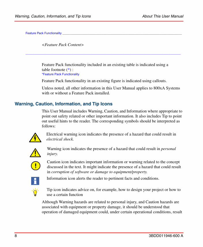
This User Manual includes Warning, Caution, and Information where appropriate to point out safety related or other important information. It also includes Tip to point out useful hints to the reader. The corresponding symbols should be interpreted as follows:
Although Warning hazards are related to personal injury, and Caution hazards are associated with equipment or property damage, it should be understood that operation of damaged equipment could, under certain operational conditions, result
Electrical warning icon indicates the presence of a hazard that could result in electrical shock.
Warning icon indicates the presence of a hazard that could result in personal injury.
Caution icon indicates important information or warning related to the concept discussed in the text. It might indicate the presence of a hazard that could result in corruption of software or damage to equipment/property.
Information icon alerts the reader to pertinent facts and conditions.
Tip icon indicates advice on, for example, how to design your project or how to use a certain function
About This User Manual Terminology
3BDD011946-600 A 9
in degraded process performance leading to personal injury or death. Therefore, fully comply with all Warning and Caution notices.
TerminologyA complete and comprehensive list of Terms is included in the System 800xA, System Guide, Functional Description (3BSE038018*). The listing includes terms and definitions as they apply to the 800xA system where the usage is different from commonly accepted industry standard definitions and definitions given in standard dictionaries such as Webster’s Dictionary of Computer Terms. Terms that uniquely apply to this instruction may be included here as part of this document.
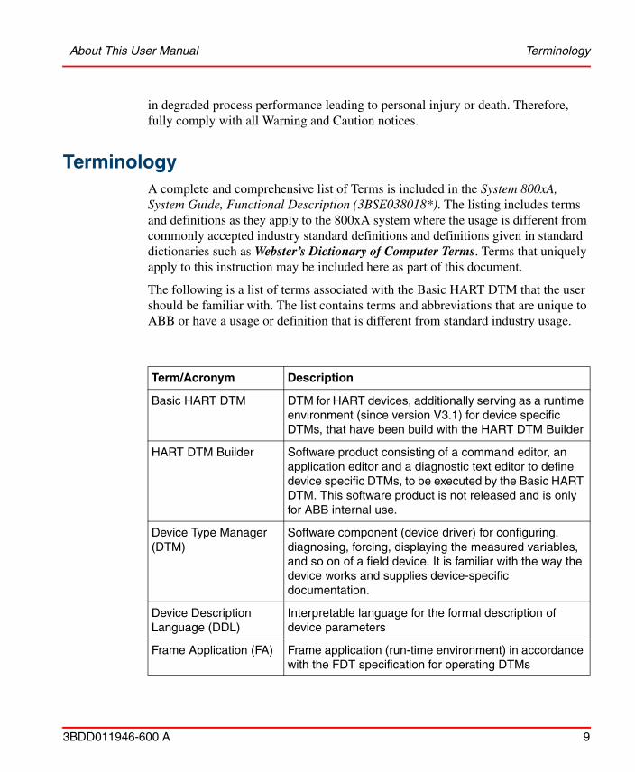
The following is a list of terms associated with the Basic HART DTM that the user should be familiar with. The list contains terms and abbreviations that are unique to ABB or have a usage or definition that is different from standard industry usage.
Term/Acronym Description
Basic HART DTM DTM for HART devices, additionally serving as a runtime environment (since version V3.1) for device specific DTMs, that have been build with the HART DTM Builder
HART DTM Builder Software product consisting of a command editor, an application editor and a diagnostic text editor to define device specific DTMs, to be executed by the Basic HART DTM. This software product is not released and is only for ABB internal use.
Device Type Manager (DTM)
Software component (device driver) for configuring, diagnosing, forcing, displaying the measured variables, and so on of a field device. It is familiar with the way the device works and supplies device-specific documentation.
Device Description Language (DDL)
Interpretable language for the formal description of device parameters
Frame Application (FA) Frame application (run-time environment) in accordance with the FDT specification for operating DTMs
Terminology About This User Manual
10 3BDD011946-600 A
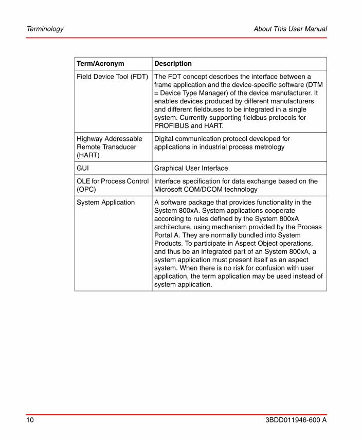
Field Device Tool (FDT) The FDT concept describes the interface between a frame application and the device-specific software (DTM = Device Type Manager) of the device manufacturer. It enables devices produced by different manufacturers and different fieldbuses to be integrated in a single system. Currently supporting fieldbus protocols for PROFIBUS and HART.
Highway Addressable Remote Transducer (HART)
Digital communication protocol developed for applications in industrial process metrology
GUI Graphical User Interface
OLE for Process Control (OPC)
Interface specification for data exchange based on the Microsoft COM/DCOM technology
System Application A software package that provides functionality in the System 800xA. System applications cooperate according to rules defined by the System 800xA architecture, using mechanism provided by the Process Portal A. They are normally bundled into System Products. To participate in Aspect Object operations, and thus be an integrated part of an System 800xA, a system application must present itself as an aspect system. When there is no risk for confusion with user application, the term application may be used instead of system application.
Term/Acronym Description
About This User Manual Related Documentation
3BDD011946-600 A 11
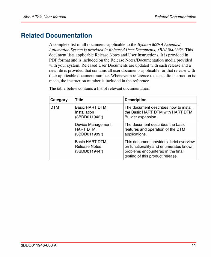
Related DocumentationA complete list of all documents applicable to the System 800xA Extended Automation System is provided in Released User Documents, 3BUA000263*. This document lists applicable Release Notes and User Instructions. It is provided in PDF format and is included on the Release Notes/Documentation media provided with your system. Released User Documents are updated with each release and a new file is provided that contains all user documents applicable for that release with their applicable document number. Whenever a reference to a specific instruction is made, the instruction number is included in the reference.
The table below contains a list of relevant documentation.
Category Title Description
DTM Basic HART DTM, Installation(3BDD011942*)
The document describes how to install the Basic HART DTM with HART DTM Builder expansion.
Device Management, HART DTM, (3BDD011939*)
The document describes the basic features and operation of the DTM applications.
Basic HART DTM, Release Notes(3BDD011944*)
This document provides a brief overview on functionality and enumerates known problems encountered in the final testing of this product release.
Related Documentation About This User Manual
12 3BDD011946-600 A
3BDD011946-600 A 13
Section 1 Introduction
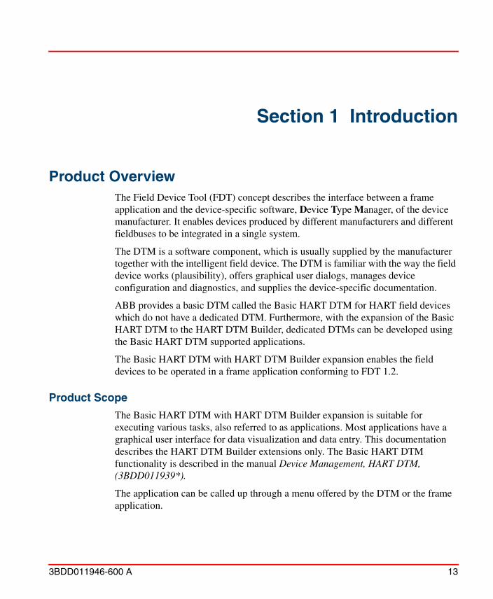
Product OverviewThe Field Device Tool (FDT) concept describes the interface between a frame application and the device-specific software, Device Type Manager, of the device manufacturer. It enables devices produced by different manufacturers and different fieldbuses to be integrated in a single system.
The DTM is a software component, which is usually supplied by the manufacturer together with the intelligent field device. The DTM is familiar with the way the field device works (plausibility), offers graphical user dialogs, manages device configuration and diagnostics, and supplies the device-specific documentation.
ABB provides a basic DTM called the Basic HART DTM for HART field devices which do not have a dedicated DTM. Furthermore, with the expansion of the Basic HART DTM to the HART DTM Builder, dedicated DTMs can be developed using the Basic HART DTM supported applications.
The Basic HART DTM with HART DTM Builder expansion enables the field devices to be operated in a frame application conforming to FDT 1.2.
Product Scope
The Basic HART DTM with HART DTM Builder expansion is suitable for executing various tasks, also referred to as applications. Most applications have a graphical user interface for data visualization and data entry. This documentation describes the HART DTM Builder extensions only. The Basic HART DTM functionality is described in the manual Device Management, HART DTM, (3BDD011939*).
The application can be called up through a menu offered by the DTM or the frame application.
Installation Section 1 Introduction
14 3BDD011946-600 A
The following DTM applications are available for the HART DTM Builder extension:
• RegistrationAllows to extend the Basic HART DTM to the HART DTM Builder.
• User Applications (via HART DTM Builder templates)The DTM menu will be extended with additional applications, which are created by using the Application Editor.
• Command EditorThe Command Editor allows to extend the universal and common practice commands delivered by the Basic HART DTM with additional private HART commands.
• Application EditorThe Application Editor allows to create new user-defined DTM applications to execute the private HART commands using graphical user interface.
• Diagnosis EditorThe Diagnosis Editor allows to create clear text messages for specific device types.
InstallationThe installation as well as the system requirements of the Basic HART DTM with HART DTM Builder expansion is described in the manual Basic HART DTM, Installation (3BDD011906*).
RegistrationA separate license key is required for the HART DTM Builder. This is associated with the one workstation computer on which the software is to be installed and operated.
To order and register the license key, follow the steps as described below:
1. Install the software on the workstation computer on which it will be used.
2. Start the Basic HART DTM in a FDT 1.2 frame application and open the Registration dialog box.
Section 1 Introduction Registration
3BDD011946-600 A 15
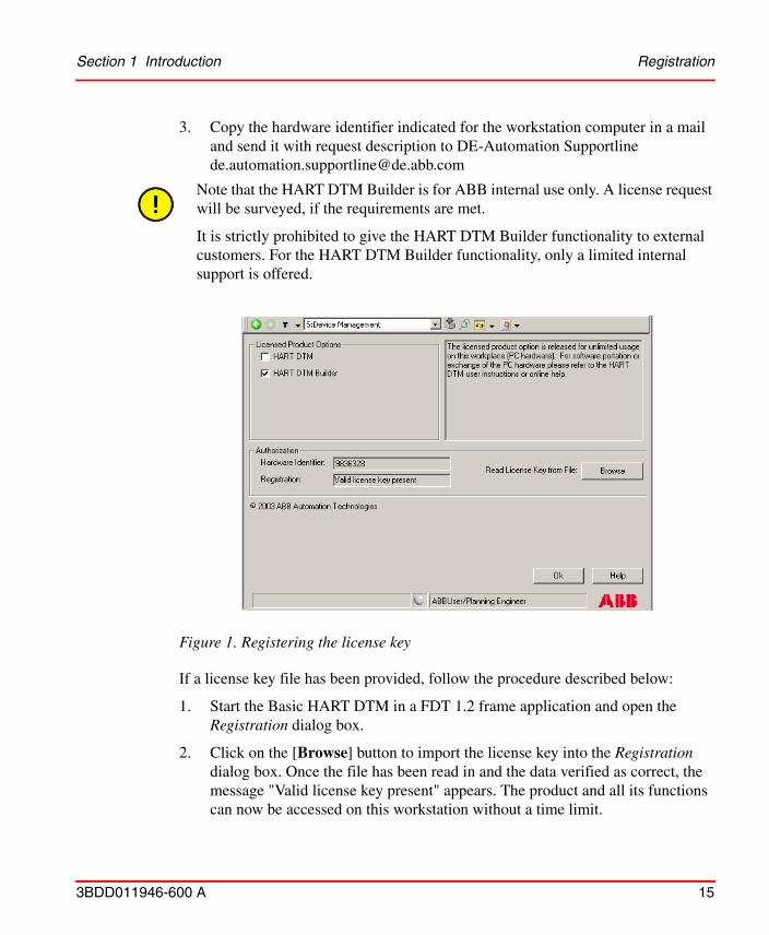
3. Copy the hardware identifier indicated for the workstation computer in a mail and send it with request description to DE-Automation Supportline [email protected]
Note that the HART DTM Builder is for ABB internal use only. A license request will be surveyed, if the requirements are met.
It is strictly prohibited to give the HART DTM Builder functionality to external customers. For the HART DTM Builder functionality, only a limited internal support is offered.
Figure 1. Registering the license key
If a license key file has been provided, follow the procedure described below:
1. Start the Basic HART DTM in a FDT 1.2 frame application and open the Registration dialog box.
2. Click on the [Browse] button to import the license key into the Registration dialog box. Once the file has been read in and the data verified as correct, the message "Valid license key present" appears. The product and all its functions can now be accessed on this workstation without a time limit.
Intended User Section 1 Introduction
16 3BDD011946-600 A
If the message "Invalid license key present" appears, check whether the license key is:
– for a different product
– for a different workstation or
– for a workstation with different hardware resources, for example, Ethernet interface card.
Intended User This configuration guide is designed for application engineers and commissioning engineers. It explains how to build device-specific DTMs using the HART DTM Builder.
The users using this manual should be familiar with the basics of the HART protocol.
3BDD011946-600 A 17
Section 2 HART DTM Builder
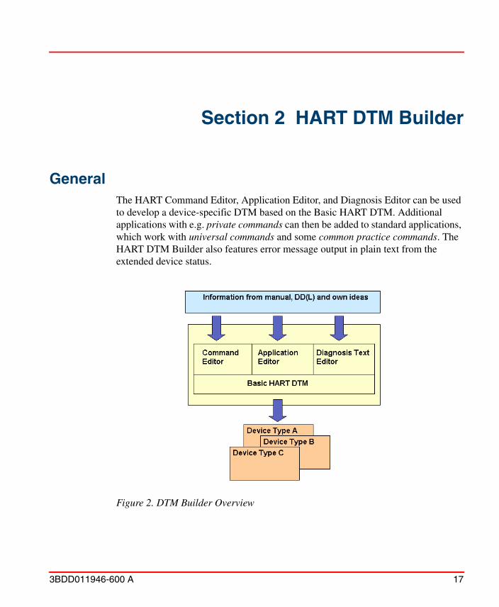
GeneralThe HART Command Editor, Application Editor, and Diagnosis Editor can be used to develop a device-specific DTM based on the Basic HART DTM. Additional applications with e.g. private commands can then be added to standard applications, which work with universal commands and some common practice commands. The HART DTM Builder also features error message output in plain text from the extended device status.
Figure 2. DTM Builder Overview
Load, Save, Import Section 2 HART DTM Builder
18 3BDD011946-600 A
Load, Save, Import
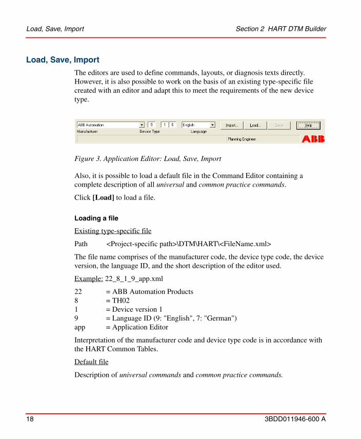
The editors are used to define commands, layouts, or diagnosis texts directly. However, it is also possible to work on the basis of an existing type-specific file created with an editor and adapt this to meet the requirements of the new device type.
Also, it is possible to load a default file in the Command Editor containing a complete description of all universal and common practice commands.
Click [Load] to load a file.
Loading a file
Existing type-specific file
Path <Project-specific path>\DTM\HART\<FileName.xml>
The file name comprises of the manufacturer code, the device type code, the device version, the language ID, and the short description of the editor used.
Example: 22_8_1_9_app.xml
22 = ABB Automation Products8 = TH021 = Device version 19 = Language ID (9: "English", 7: "German")app = Application Editor
Interpretation of the manufacturer code and device type code is in accordance with the HART Common Tables.
Default file
Description of universal commands and common practice commands.
Figure 3. Application Editor: Load, Save, Import
Section 2 HART DTM Builder Load, Save, Import
3BDD011946-600 A 19
Path <System drive>:\Program Files(x86)\ABB Industrial IT\EngineerIT\DTM\Basic HART DTM\xml\_DefaultHartCommands.xml
Attribute: Read-only
Check that the file name is correct before saving the file. The manufacturer code, the device type code, the version number, and the editor abbreviation are important as they create the reference to the planned and installed device type during the definition phase (offline) and subsequently during operation (online).
Saving a file
Click [Save] to save a file. On saving, the XML file name reflects the version information.
Versioning a file
Each saved file contains two version information:
• A major version, which offers the possibility to create different XML files for the same device type (manufacturer ID and device ID).
• A minor version, which includes a version information in the existing XML file. Only the internal XML version information is changed.
The file’s write protection feature must never be violated. Modifying the commands written in the file may cause the applications to malfunction.
[Save] always saves the file to the project related path for users who are granted the access rights.
Load, Save, Import Section 2 HART DTM Builder
20 3BDD011946-600 A
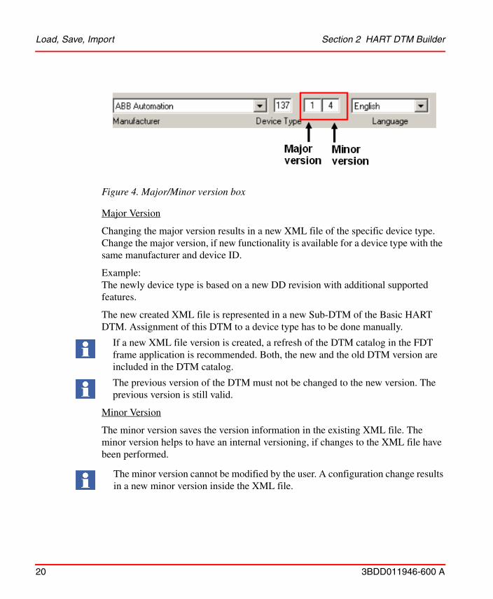
Major Version
Changing the major version results in a new XML file of the specific device type. Change the major version, if new functionality is available for a device type with the same manufacturer and device ID.
Example:The newly device type is based on a new DD revision with additional supported features.
The new created XML file is represented in a new Sub-DTM of the Basic HART DTM. Assignment of this DTM to a device type has to be done manually.
Minor Version
The minor version saves the version information in the existing XML file. The minor version helps to have an internal versioning, if changes to the XML file have been performed.
Figure 4. Major/Minor version box
If a new XML file version is created, a refresh of the DTM catalog in the FDT frame application is recommended. Both, the new and the old DTM version are included in the DTM catalog.
The previous version of the DTM must not be changed to the new version. The previous version is still valid.
The minor version cannot be modified by the user. A configuration change results in a new minor version inside the XML file.
Section 2 HART DTM Builder User Roles
3BDD011946-600 A 21
Importing a file
The Import function can be used to combine data from two files. These files must have been created with the same editor.
• Command file (_cmd.xml): The Commands/parameters from the imported file are added to the file that is to be loaded. Existing commands are not overwritten with those from the import file.
• Layout file (_app.xml): All the applications from the import file are added to the file that is to be loaded. If an import application has the same name as an existing application, then the Application Editor changes the name of the import application.
• Diagnosis text file (_dgn.xml): In this file, data convergence is determined by byte interpretation. Only if the interpretations are identical for bit, integer, and so on, the diagnosis texts for unused bits, integer values, and so on are taken from the import file and added to the loaded file.
User Roles
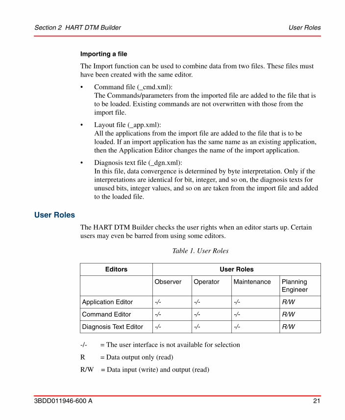
The HART DTM Builder checks the user rights when an editor starts up. Certain users may even be barred from using some editors.
-/- = The user interface is not available for selection
R = Data output only (read)
R/W = Data input (write) and output (read)
Table 1. User Roles
Editors User Roles
Observer Operator Maintenance Planning Engineer
Application Editor -/- -/- -/- R/W
Command Editor -/- -/- -/- R/W
Diagnosis Text Editor -/- -/- -/- R/W
HART Command Editor Section 2 HART DTM Builder
22 3BDD011946-600 A
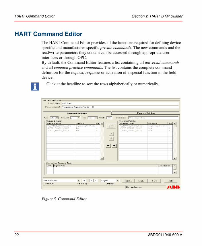
HART Command EditorThe HART Command Editor provides all the functions required for defining device-specific and manufacturer-specific private commands. The new commands and the read/write parameters they contain can be accessed through appropriate user interfaces or through OPC. By default, the Command Editor features a list containing all universal commands and all common practice commands. The list contains the complete command definition for the request, response or activation of a special function in the field device.
Click at the headline to sort the rows alphabetically or numerically.
Figure 5. Command Editor
Section 2 HART DTM Builder Parameter Definition
3BDD011946-600 A 23
Parameter Definition
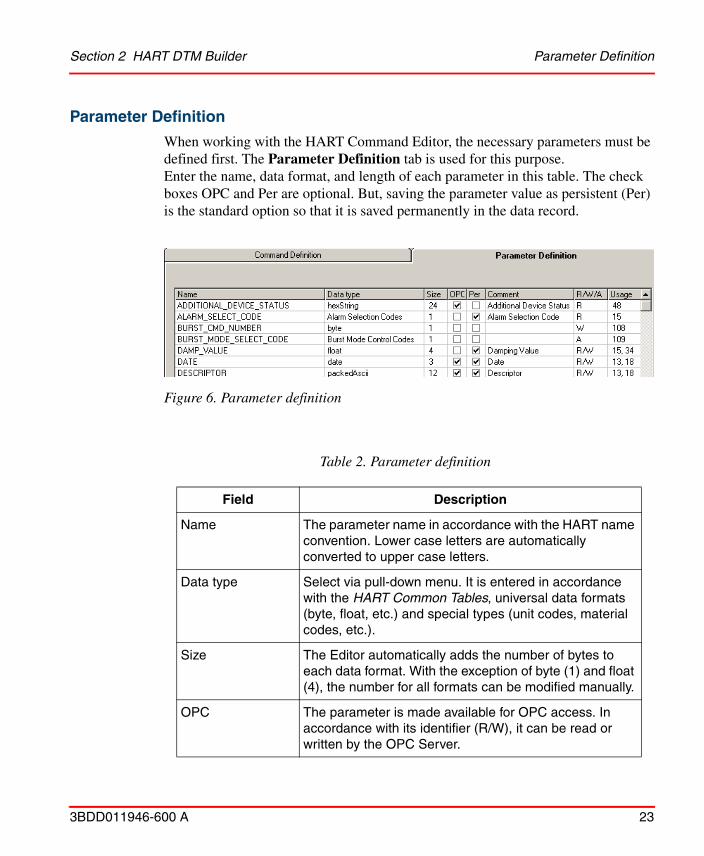
When working with the HART Command Editor, the necessary parameters must be defined first. The Parameter Definition tab is used for this purpose. Enter the name, data format, and length of each parameter in this table. The check boxes OPC and Per are optional. But, saving the parameter value as persistent (Per) is the standard option so that it is saved permanently in the data record.
Figure 6. Parameter definition
Table 2. Parameter definition
Field Description
Name The parameter name in accordance with the HART name convention. Lower case letters are automatically converted to upper case letters.
Data type Select via pull-down menu. It is entered in accordance with the HART Common Tables, universal data formats (byte, float, etc.) and special types (unit codes, material codes, etc.).
Size The Editor automatically adds the number of bytes to each data format. With the exception of byte (1) and float (4), the number for all formats can be modified manually.
OPC The parameter is made available for OPC access. In accordance with its identifier (R/W), it can be read or written by the OPC Server.
Parameter Definition Section 2 HART DTM Builder
24 3BDD011946-600 A
Per The parameter value is saved permanently in the instance data record of the field device and thereby made available to the OPC Server.
Comment Additional information about the command defined
R/W/A The Editor assigns additional information (Read/Write/Action) using the selection made during command definition.
Usage Command (number) in which the parameter is used. The Editor adds this information independently. A parameter may be used in a number of commands.
The length of a user-defined parameter with data type HexString will not be checked. The user can enter a value of any length. Note:
• Maximal length of an hexstring parameter is twice the declared length in size column of the parameter (e.g. hexstring size = 12, allowed a parameter input up to 24 characters.
• Only input values from data type hexadecimal can be entered.
If parameters and their attributes are changed, for example, persistence or OPC behavior, the applied changes will not be updated in the Offline List View, if this window is open in parallel. The changes will be reflected only when a next DTM is instantiated.
Table 2. Parameter definition (Continued)
Field Description
Section 2 HART DTM Builder Command Definition
3BDD011946-600 A 25
Command Definition
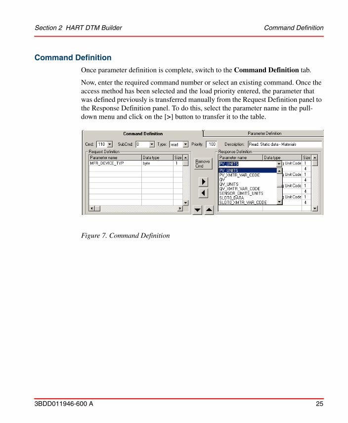
Once parameter definition is complete, switch to the Command Definition tab.
Now, enter the required command number or select an existing command. Once the access method has been selected and the load priority entered, the parameter that was defined previously is transferred manually from the Request Definition panel to the Response Definition panel. To do this, select the parameter name in the pull-down menu and click on the [>] button to transfer it to the table.
Figure 7. Command Definition
Command Definition Section 2 HART DTM Builder
26 3BDD011946-600 A
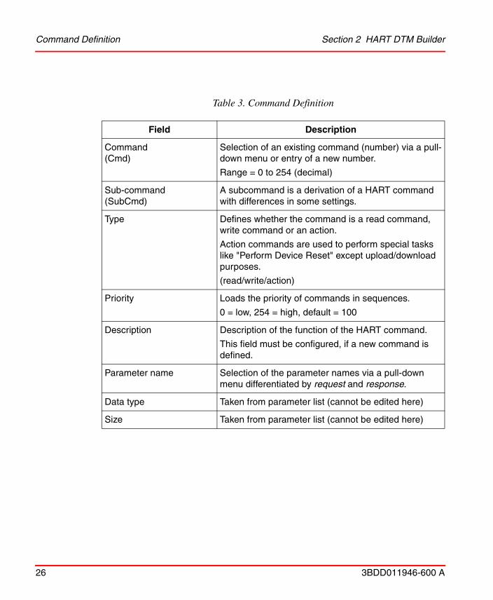
Table 3. Command Definition
Field Description
Command (Cmd)
Selection of an existing command (number) via a pull-down menu or entry of a new number.
Range = 0 to 254 (decimal)
Sub-command(SubCmd)
A subcommand is a derivation of a HART command with differences in some settings.
Type Defines whether the command is a read command, write command or an action.
Action commands are used to perform special tasks like "Perform Device Reset" except upload/download purposes.
(read/write/action)
Priority Loads the priority of commands in sequences.
0 = low, 254 = high, default = 100
Description Description of the function of the HART command.
This field must be configured, if a new command is defined.
Parameter name Selection of the parameter names via a pull-down menu differentiated by request and response.
Data type Taken from parameter list (cannot be edited here)
Size Taken from parameter list (cannot be edited here)
Section 2 HART DTM Builder Command Definition
3BDD011946-600 A 27
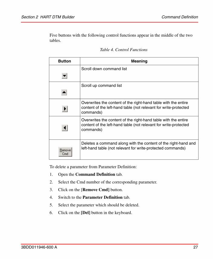
Five buttons with the following control functions appear in the middle of the two tables.
To delete a parameter from Parameter Definition:
1. Open the Command Definition tab.
2. Select the Cmd number of the corresponding parameter.
3. Click on the [Remove Cmd] button.
4. Switch to the Parameter Definition tab.
5. Select the parameter which should be deleted.
6. Click on the [Del] button in the keyboard.
Table 4. Control Functions
Button Meaning
Scroll down command list
Scroll up command list
Overwrites the content of the right-hand table with the entire content of the left-hand table (not relevant for write-protected commands)
Overwrites the content of the right-hand table with the entire content of the left-hand table (not relevant for write-protected commands)
Deletes a command along with the content of the right-hand and left-hand table (not relevant for write-protected commands)
Command Definition Section 2 HART DTM Builder
28 3BDD011946-600 A
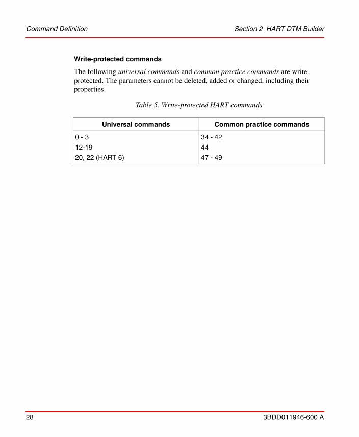
Write-protected commands
The following universal commands and common practice commands are write-protected. The parameters cannot be deleted, added or changed, including their properties.
Table 5. Write-protected HART commands
Universal commands Common practice commands
0 - 3
12-19
20, 22 (HART 6)
34 - 42
44
47 - 49
Section 2 HART DTM Builder User-Defined Response Codes
3BDD011946-600 A 29
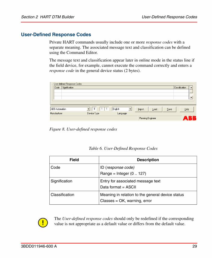
User-Defined Response Codes
Private HART commands usually include one or more response codes with a separate meaning. The associated message text and classification can be defined using the Command Editor.
The message text and classification appear later in online mode in the status line if the field device, for example, cannot execute the command correctly and enters a response code in the general device status (2 bytes).
Figure 8. User-defined response codes
Table 6. User-Defined Response Codes
Field Description
Code ID (response code)
Range = Integer (0 .. 127)
Signification Entry for associated message text
Data format = ASCII
Classification Meaning in relation to the general device status
Classes = OK, warning, error
The User-defined response codes should only be redefined if the corresponding value is not appropriate as a default value or differs from the default value.
Application Editor Section 2 HART DTM Builder
30 3BDD011946-600 A
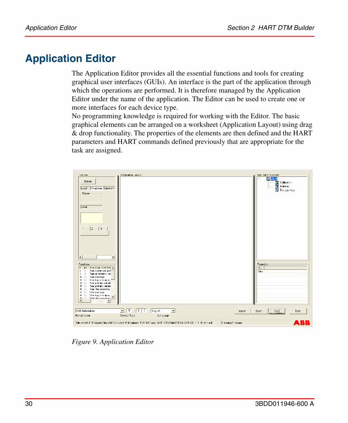
Application EditorThe Application Editor provides all the essential functions and tools for creating graphical user interfaces (GUIs). An interface is the part of the application through which the operations are performed. It is therefore managed by the Application Editor under the name of the application. The Editor can be used to create one or more interfaces for each device type. No programming knowledge is required for working with the Editor. The basic graphical elements can be arranged on a worksheet (Application Layout) using drag & drop functionality. The properties of the elements are then defined and the HART parameters and HART commands defined previously that are appropriate for the task are assigned.
Figure 9. Application Editor
Section 2 HART DTM Builder Toolbox
3BDD011946-600 A 31
Toolbox
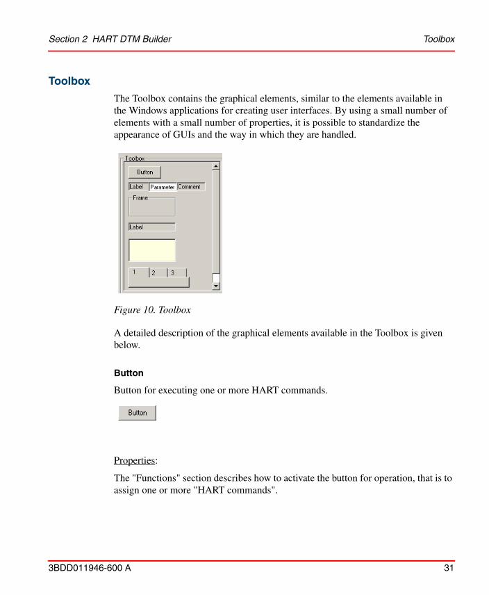
The Toolbox contains the graphical elements, similar to the elements available in the Windows applications for creating user interfaces. By using a small number of elements with a small number of properties, it is possible to standardize the appearance of GUIs and the way in which they are handled.
A detailed description of the graphical elements available in the Toolbox is given below.
Button
Button for executing one or more HART commands.
Properties:
The "Functions" section describes how to activate the button for operation, that is to assign one or more "HART commands".
Figure 10. Toolbox
Toolbox Section 2 HART DTM Builder
32 3BDD011946-600 A
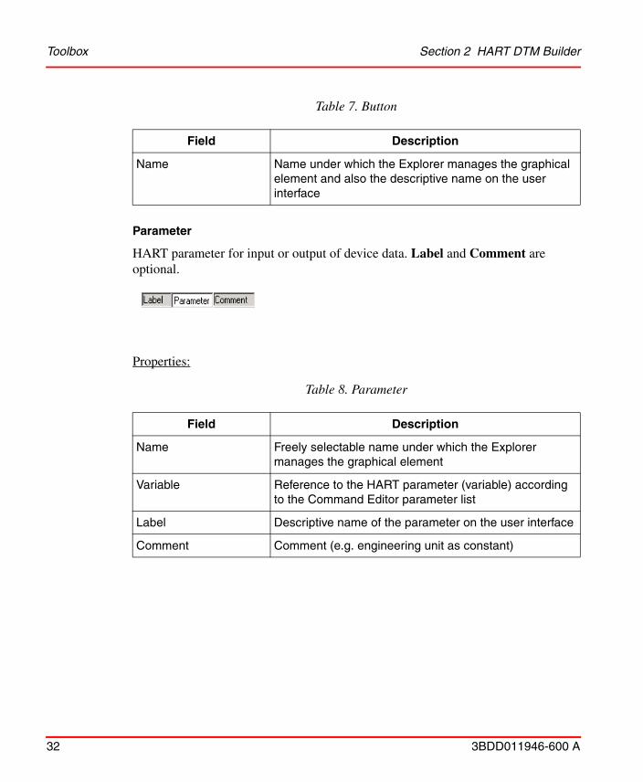
Parameter
HART parameter for input or output of device data. Label and Comment are optional.
Properties:
Table 7. Button
Field Description
Name Name under which the Explorer manages the graphical element and also the descriptive name on the user interface
Table 8. Parameter
Field Description
Name Freely selectable name under which the Explorer manages the graphical element
Variable Reference to the HART parameter (variable) according to the Command Editor parameter list
Label Descriptive name of the parameter on the user interface
Comment Comment (e.g. engineering unit as constant)
Section 2 HART DTM Builder Toolbox
3BDD011946-600 A 33
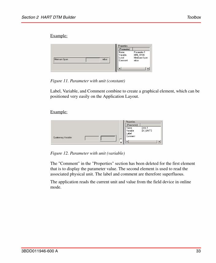
Example:
Label, Variable, and Comment combine to create a graphical element, which can be positioned very easily on the Application Layout.
Example:
The "Comment" in the "Properties" section has been deleted for the first element that is to display the parameter value. The second element is used to read the associated physical unit. The label and comment are therefore superfluous.
The application reads the current unit and value from the field device in online mode.
Figure 11. Parameter with unit (constant)
Figure 12. Parameter with unit (variable)
Toolbox Section 2 HART DTM Builder
34 3BDD011946-600 A
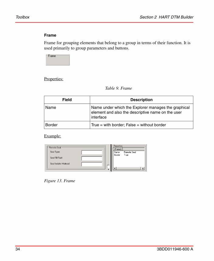
Frame
Frame for grouping elements that belong to a group in terms of their function. It is used primarily to group parameters and buttons.
Properties:
Example:
Table 9. Frame
Field Description
Name Name under which the Explorer manages the graphical element and also the descriptive name on the user interface
Border True = with border; False = without border
Figure 13. Frame
Section 2 HART DTM Builder Toolbox
3BDD011946-600 A 35
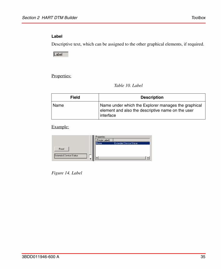
Label
Descriptive text, which can be assigned to the other graphical elements, if required.
Properties:
Example:
Table 10. Label
Field Description
Name Name under which the Explorer manages the graphical element and also the descriptive name on the user interface
Figure 14. Label
Toolbox Section 2 HART DTM Builder
36 3BDD011946-600 A
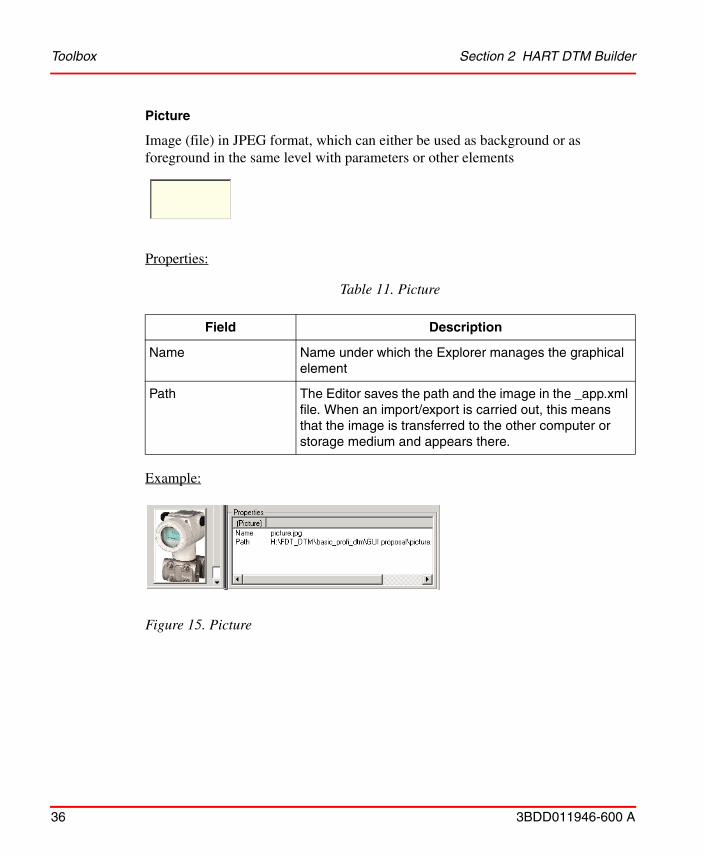
Picture
Image (file) in JPEG format, which can either be used as background or as foreground in the same level with parameters or other elements
Properties:
Example:
Table 11. Picture
Field Description
Name Name under which the Explorer manages the graphical element
Path The Editor saves the path and the image in the _app.xml file. When an import/export is carried out, this means that the image is transferred to the other computer or storage medium and appears there.
Figure 15. Picture
Section 2 HART DTM Builder Toolbox
3BDD011946-600 A 37
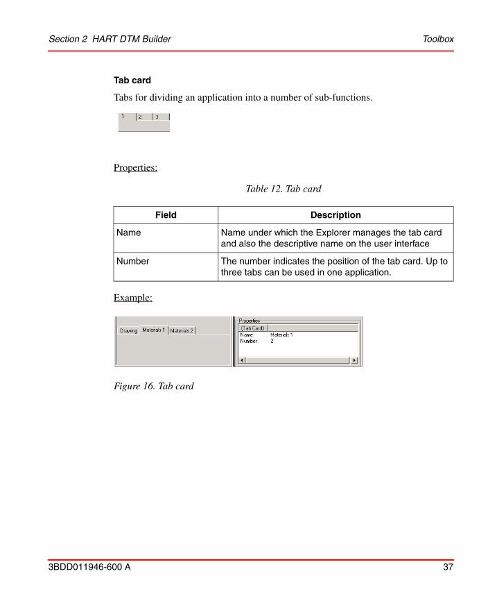
Tab card
Tabs for dividing an application into a number of sub-functions.
Properties:
Example:
Table 12. Tab card
Field Description
Name Name under which the Explorer manages the tab card and also the descriptive name on the user interface
Number The number indicates the position of the tab card. Up to three tabs can be used in one application.
Figure 16. Tab card
Application Layout Section 2 HART DTM Builder
38 3BDD011946-600 A
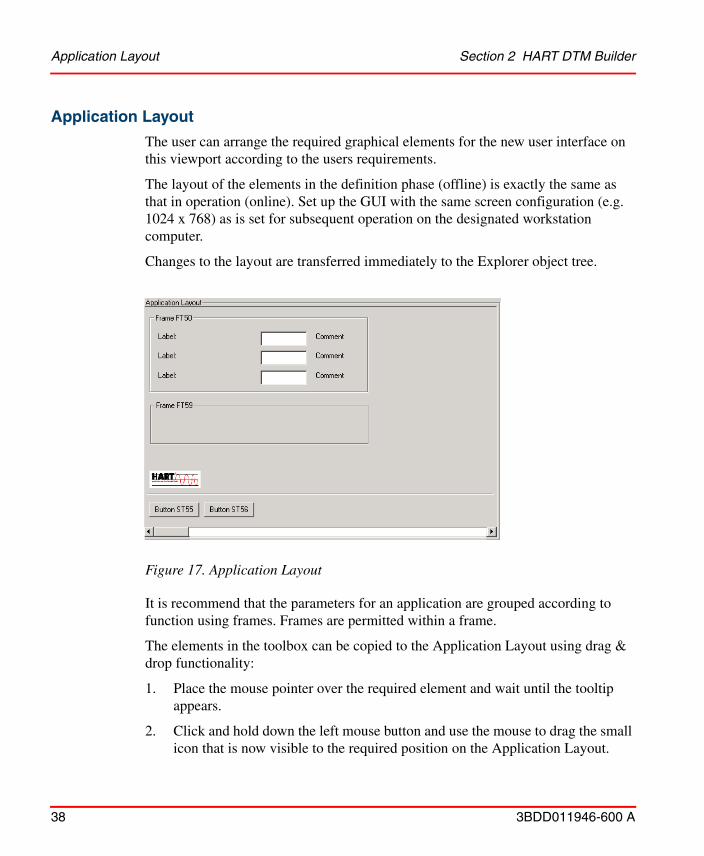
Application Layout
The user can arrange the required graphical elements for the new user interface on this viewport according to the users requirements.
The layout of the elements in the definition phase (offline) is exactly the same as that in operation (online). Set up the GUI with the same screen configuration (e.g. 1024 x 768) as is set for subsequent operation on the designated workstation computer.
Changes to the layout are transferred immediately to the Explorer object tree.
It is recommend that the parameters for an application are grouped according to function using frames. Frames are permitted within a frame.
The elements in the toolbox can be copied to the Application Layout using drag & drop functionality:
1. Place the mouse pointer over the required element and wait until the tooltip appears.
2. Click and hold down the left mouse button and use the mouse to drag the small icon that is now visible to the required position on the Application Layout.
Figure 17. Application Layout
Section 2 HART DTM Builder Application Layout
3BDD011946-600 A 39
3. The element will reappear once the mouse button is released. Select the element again and move it in order to get it into exactly the correct position.
Once an element has been selected, it can be positioned very precisely using the cursor keys.
Application Explorer Section 2 HART DTM Builder
40 3BDD011946-600 A
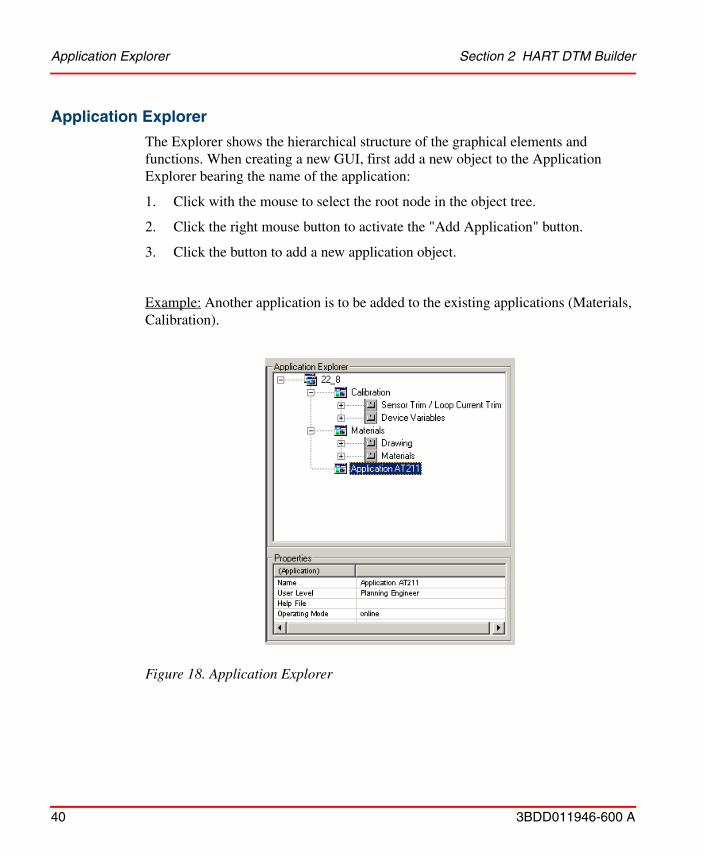
Application Explorer
The Explorer shows the hierarchical structure of the graphical elements and functions. When creating a new GUI, first add a new object to the Application Explorer bearing the name of the application:
1. Click with the mouse to select the root node in the object tree.
2. Click the right mouse button to activate the "Add Application" button.
3. Click the button to add a new application object.
Example: Another application is to be added to the existing applications (Materials, Calibration).
Figure 18. Application Explorer
Section 2 HART DTM Builder Application Explorer
3BDD011946-600 A 41
The application object now requires the following entries to be made (see Properties) to complete the description.
1. Change the default name, that is enter the actual name of the application.
2. Select the appropriate user role for the application.
3. If available, enter the path to a Help file.
4. Select the operating mode.
It is easier to carry out actions affecting a number of graphical elements (copying, moving, deleting, etc.) in the Explorer than in the Application Layout. Changes to the object layout in the tree are automatically applied to the layout and vice versa.
Functions Section 2 HART DTM Builder
42 3BDD011946-600 A
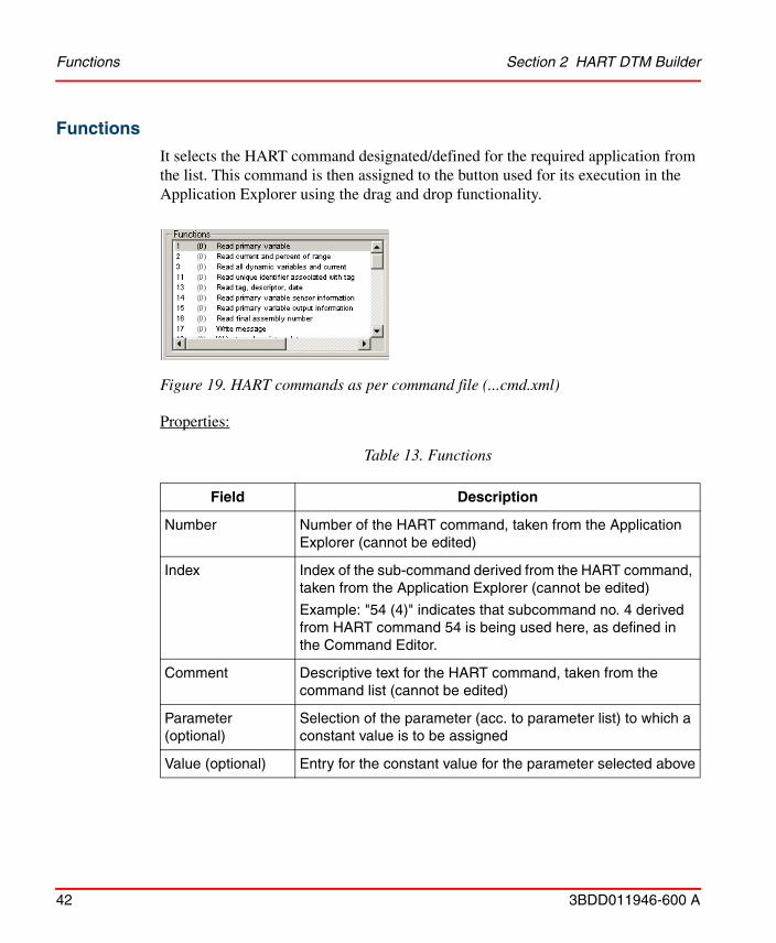
Functions
It selects the HART command designated/defined for the required application from the list. This command is then assigned to the button used for its execution in the Application Explorer using the drag and drop functionality.
Properties:
Figure 19. HART commands as per command file (...cmd.xml)
Table 13. Functions
Field Description
Number Number of the HART command, taken from the Application Explorer (cannot be edited)
Index Index of the sub-command derived from the HART command, taken from the Application Explorer (cannot be edited)
Example: "54 (4)" indicates that subcommand no. 4 derived from HART command 54 is being used here, as defined in the Command Editor.
Comment Descriptive text for the HART command, taken from the command list (cannot be edited)
Parameter (optional)
Selection of the parameter (acc. to parameter list) to which a constant value is to be assigned
Value (optional) Entry for the constant value for the parameter selected above
Section 2 HART DTM Builder Functions
3BDD011946-600 A 43
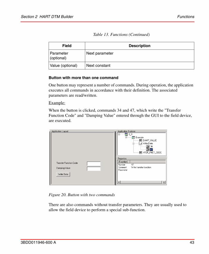
Button with more than one command
One button may represent a number of commands. During operation, the application executes all commands in accordance with their definition. The associated parameters are read/written.
Example:
When the button is clicked, commands 34 and 47, which write the "Transfer Function Code" and "Damping Value" entered through the GUI to the field device, are executed.
There are also commands without transfer parameters. They are usually used to allow the field device to perform a special sub-function.
Parameter (optional)
Next parameter
Value (optional) Next constant
Figure 20. Button with two commands
Table 13. Functions (Continued)
Field Description
Functions Section 2 HART DTM Builder
44 3BDD011946-600 A
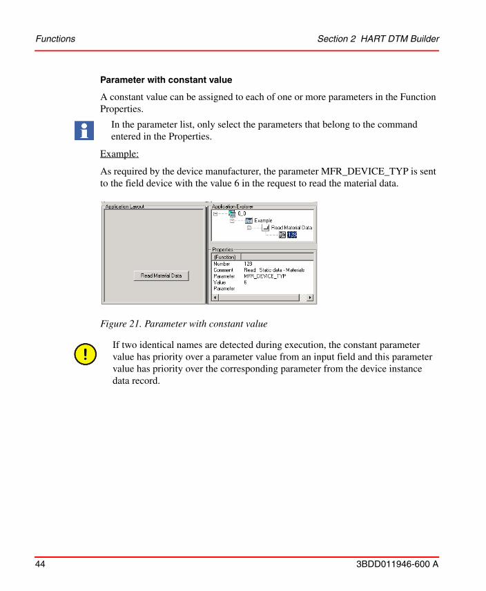
Parameter with constant value
A constant value can be assigned to each of one or more parameters in the Function Properties.
Example:
As required by the device manufacturer, the parameter MFR_DEVICE_TYP is sent to the field device with the value 6 in the request to read the material data.
In the parameter list, only select the parameters that belong to the command entered in the Properties.
Figure 21. Parameter with constant value
If two identical names are detected during execution, the constant parameter value has priority over a parameter value from an input field and this parameter value has priority over the corresponding parameter from the device instance data record.
Section 2 HART DTM Builder Status Bar
3BDD011946-600 A 45
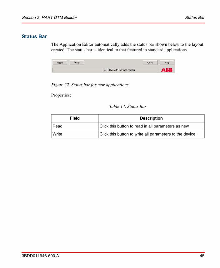
Status Bar
Table 14. Status Bar
Field Description
Read Click this button to read in all parameters as new
Write Click this button to write all parameters to the device
The Application Editor automatically adds the status bar shown below to the layout created. The status bar is identical to that featured in standard applications.
Properties:
Figure 22. Status bar for new applications
Diagnosis Text Editor Section 2 HART DTM Builder
46 3BDD011946-600 A
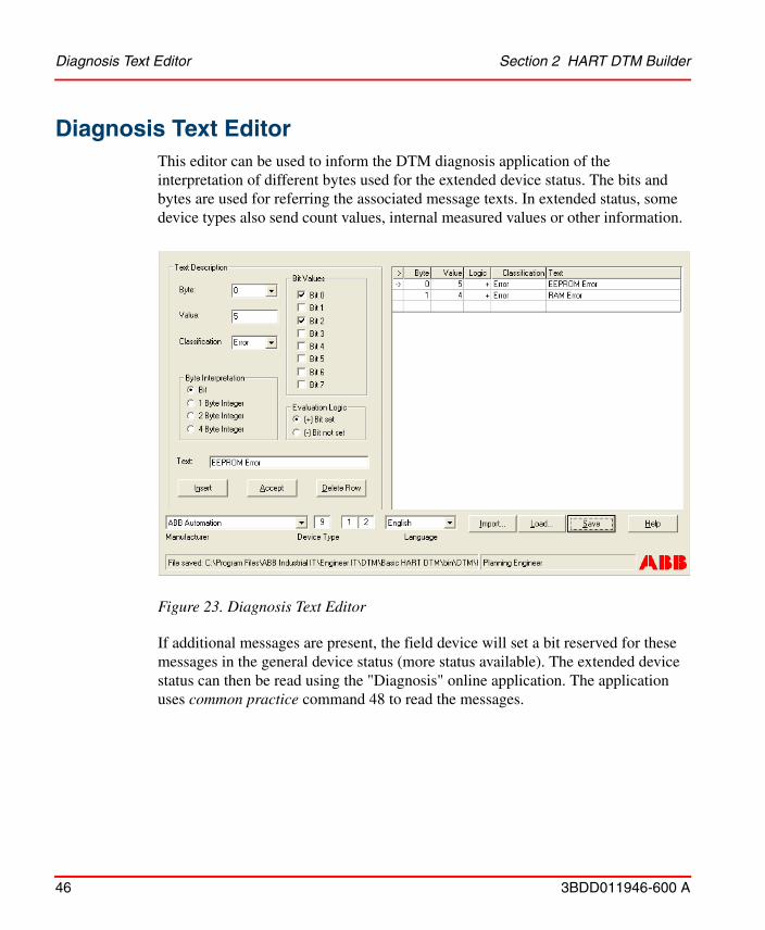
Diagnosis Text EditorThis editor can be used to inform the DTM diagnosis application of the interpretation of different bytes used for the extended device status. The bits and bytes are used for referring the associated message texts. In extended status, some device types also send count values, internal measured values or other information.
If additional messages are present, the field device will set a bit reserved for these messages in the general device status (more status available). The extended device status can then be read using the "Diagnosis" online application. The application uses common practice command 48 to read the messages.
Figure 23. Diagnosis Text Editor
Section 2 HART DTM Builder Diagnosis Text Editor
3BDD011946-600 A 47
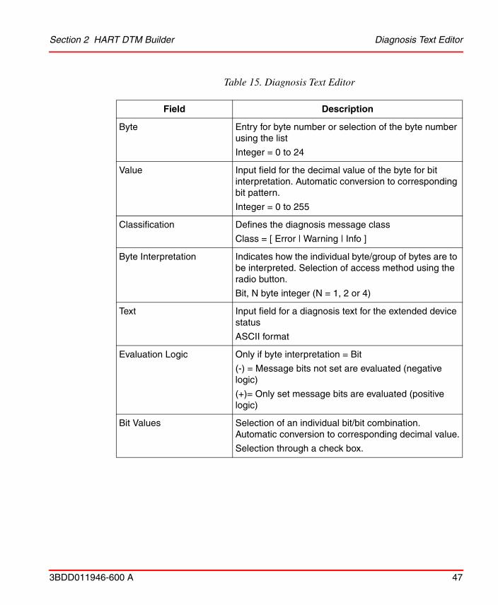
Table 15. Diagnosis Text Editor
Field Description
Byte Entry for byte number or selection of the byte number using the list
Integer = 0 to 24
Value Input field for the decimal value of the byte for bit interpretation. Automatic conversion to corresponding bit pattern.
Integer = 0 to 255
Classification Defines the diagnosis message class
Class = [ Error | Warning | Info ]
Byte Interpretation Indicates how the individual byte/group of bytes are to be interpreted. Selection of access method using the radio button.
Bit, N byte integer (N = 1, 2 or 4)
Text Input field for a diagnosis text for the extended device status
ASCII format
Evaluation Logic Only if byte interpretation = Bit
(-) = Message bits not set are evaluated (negative logic)
(+)= Only set message bits are evaluated (positive logic)
Bit Values Selection of an individual bit/bit combination. Automatic conversion to corresponding decimal value.
Selection through a check box.
Bit(s) Definition Section 2 HART DTM Builder
48 3BDD011946-600 A
Bit(s) Definition
Once the byte to be interpreted (0 to 24) has been selected and the interpretation method entered, the user can assign a dedicated message text to the individual bits for each bit combination. It would also be possible to interpret a variant, e.g. 4 individual bits and 4 bits as a combination, using the Editor.
Description of individual bits
The field device can send up to of 8 messages in parallel in one message cycle and one byte.
In the example below, bit 2 of byte 1 has been assigned to the message text "RAM error". All user-defined messages appear in the list on the right-hand side.
The steps to follow are:
1. Enter or select from the list the number of the byte to be interpreted.
2. In the Bit Interpretation, select the required bit by clicking the option button next to it. Else, it can be done by entering the value in the Value text box.
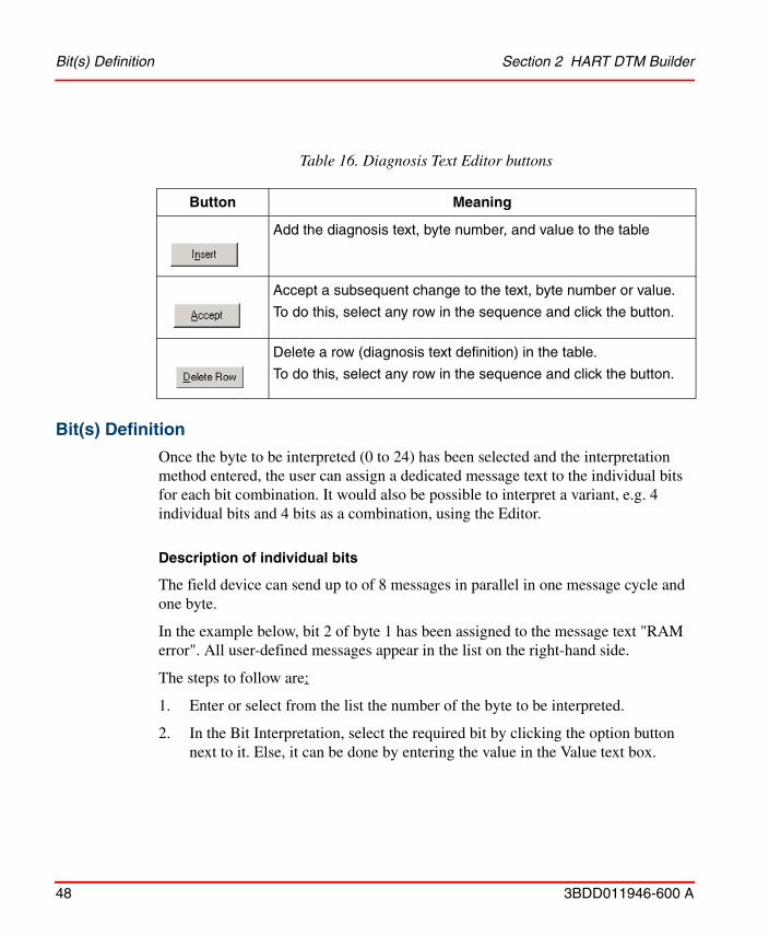
Table 16. Diagnosis Text Editor buttons
Button Meaning
Add the diagnosis text, byte number, and value to the table
Accept a subsequent change to the text, byte number or value.
To do this, select any row in the sequence and click the button.
Delete a row (diagnosis text definition) in the table.
To do this, select any row in the sequence and click the button.
Section 2 HART DTM Builder Bit(s) Definition
3BDD011946-600 A 49
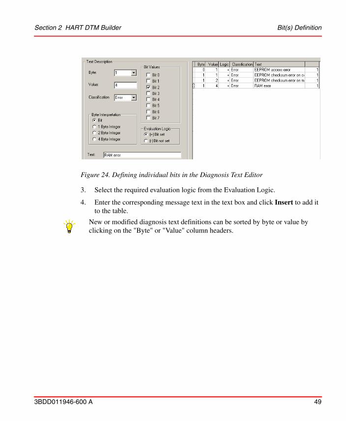
3. Select the required evaluation logic from the Evaluation Logic.
4. Enter the corresponding message text in the text box and click Insert to add it to the table.
New or modified diagnosis text definitions can be sorted by byte or value by clicking on the "Byte" or "Value" column headers.
Figure 24. Defining individual bits in the Diagnosis Text Editor
Bit(s) Definition Section 2 HART DTM Builder
50 3BDD011946-600 A
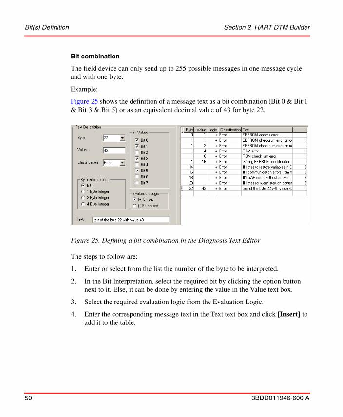
Bit combination
The field device can only send up to 255 possible messages in one message cycle and with one byte.
Example:
Figure 25 shows the definition of a message text as a bit combination (Bit 0 & Bit 1 & Bit 3 & Bit 5) or as an equivalent decimal value of 43 for byte 22.
The steps to follow are:
1. Enter or select from the list the number of the byte to be interpreted.
2. In the Bit Interpretation, select the required bit by clicking the option button next to it. Else, it can be done by entering the value in the Value text box.
3. Select the required evaluation logic from the Evaluation Logic.
4. Enter the corresponding message text in the Text text box and click [Insert] to add it to the table.
Figure 25. Defining a bit combination in the Diagnosis Text Editor
Section 2 HART DTM Builder Byte(s) Definition
3BDD011946-600 A 51
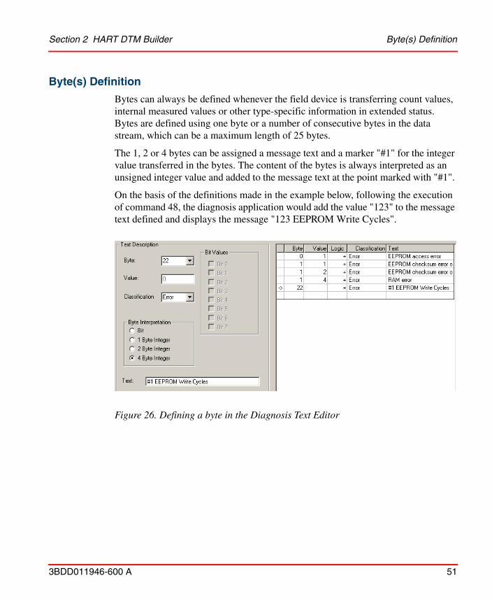
Byte(s) Definition
Bytes can always be defined whenever the field device is transferring count values, internal measured values or other type-specific information in extended status. Bytes are defined using one byte or a number of consecutive bytes in the data stream, which can be a maximum length of 25 bytes.
The 1, 2 or 4 bytes can be assigned a message text and a marker "#1" for the integer value transferred in the bytes. The content of the bytes is always interpreted as an unsigned integer value and added to the message text at the point marked with "#1".
On the basis of the definitions made in the example below, following the execution of command 48, the diagnosis application would add the value "123" to the message text defined and displays the message "123 EEPROM Write Cycles".
Figure 26. Defining a byte in the Diagnosis Text Editor
Byte(s) Definition Section 2 HART DTM Builder
52 3BDD011946-600 A
3BDD011946-600 A 53
AApplication Editor 30Application Explorer 40Application Layout 38
BBasic HART DTM 13Button 31Buttons 27
CClassification 29Code 29Command 26Command Definition 25Command File 21
DDevice Type Manager 13Diagnosis Text File 21
EExplorer Object Tree 38
FFDT 13Field Device Tool 13Frame 34Functions 42
HHART Command Editor 22
IImport 18Installation 14
LLabel 32Layout File 21Load 18
MMajor Version 20Minor Version 20
PParameter 32Parameter Definition 23Picture 36Priority 26
RRead 45Registration 14
SSave 18Signification 29Software Environment 16Status Bar 45Sub-Command 26
TTab Card 37
Index
3BDD011946-600 A 54
Toolbox 31
UUser Roles 21User-Defined Response Codes 29
VVersioning 19
WWrite 45Write-protected 28

Power and productivity for a better worldTM
Contact us
Copyright© 2016 ABB.All rights reserved.
3BD
D01
1946
-600
Awww.abb.com/800xAwww.abb.com/controlsystems