micom p342,p343(technical guide) (pdf, 1838kb)
TRANSCRIPT


MiCOM P342, P343 GuidesGenerator Protection Relays
This version of the Technical Guide is specific to the following models
Model Number Software Number P342------0070C P342------0070-A/B/C P343------0070C P343------0070-A/B/C
For other models / software versions, please contact ALSTOM T&D – Energy, Automation & Information for the relevant information.
(Software versions P342------0010*, P342------0020*, P342------0030*, P342------0040*, P342------0050* and P343------0010*, P343------0020*, P343------0030*, P343------0040*, P343------0050* are not supported by this menu database, see TG8614A (0010), TG8614B (0020 – 0040), P34x/EN T/C11 (0050) and P34x/EN T/D22 (0060) for information on the menu database for these software versions)
Technical GuideMiCOM P342, P343
Generator Protection Relays
Volume 1


Technical Guide P34x/EN T/F33
MiCOM P342, P343
GENERATOR PROTECTION RELAYS
MICOM P342, P343
CONTENT
Issue Control
Handling of Electronic Equipment
Safety Instructions
Introduction P34x/EN IT/F33
Application Notes P34x/EN AP/F33
Relay Description P34x/EN HW/F33
Technical Data P34x/EN TD/F33
SCADA Communications P34x/EN CT/F33
Relay Menu Database P34x/EN GC/F33
External Connection Diagrams P34x/EN CO/F33
Hardware/Software Version History and Compatibility P34x/EN VC/E33

Application Notes P34x/EN AP/F33
MiCOM P342, P343
APPLICATION NOTES

P34x/EN AP/F33 Application Notes
MiCOM P342, P343
Application Notes P34x/EN AP/F33
MiCOM P342, P343 Page 1/176
CONTENT
1. INTRODUCTION 11
1.1 Protection of generators 11
1.2 MiCOM Generator protection relays 12
1.2.1 Protection features 13
1.2.2 Non-protection features 14
2. APPLICATION OF INDIVIDUAL PROTECTION FUNCTIONS 14
2.1 Configuration column 14
2.2 CT and VT ratios 17
2.3 Generator differential protection 17
2.3.1 Biased differential protection 19
2.3.2 Setting guidelines for biased differential protection 20
2.3.3 High impedance differential protection 21
2.3.4 Setting guidelines for high impedance differential protection 22
2.3.5 Interturn (split phase) protection 26
2.3.5.1 Differential interturn protection 26
2.3.5.2 Application of biased differential protection for interturn protection 27
2.3.5.3 Application of overcurrent protection for interturn protection 29
2.3.5.4 Interturn protection by zero sequence voltage measurement 30
2.4 Phase fault overcurrent protection 32
2.4.1 RI curve 34
2.4.2 Application of timer hold facility 34
2.4.3 Setting guidelines for overcurrent protection 35
2.5 System back-up protection 35
2.5.1 Voltage dependant overcurrent protection 38
2.5.1.1 Voltage controlled overcurrent protection 38
2.5.1.2 Voltage restrained overcurrent protection 40
2.5.1.3 Setting guidelines for voltage controlled overcurrent function 41
2.5.2 Under impedance protection 43
2.5.2.1 Setting guidelines for under impedance function 44
2.6 Undervoltage protection function (27) 44
2.6.1 Setting guidelines for undervoltage protection 46
2.7 Overvoltage protection 47

P34x/EN AP/F33 Application Notes
Page 2/176 MiCOM P342, P343
2.7.1 Setting guidelines for overvoltage protection 48
2.8 Underfrequency protection 49
2.8.1 Setting guidelines for underfrequency protection 50
2.9 Overfrequency protection function 52
2.9.1 Setting guidelines for overfrequency protection 52
2.10 Field failure protection function (40) 53
2.10.1 Setting guidelines for field failure protection 55
2.10.1.1 Impedance element 1 55
2.10.1.2 Impedance element 2 56
2.10.1.3 Power factor element 56
2.11 Negative phase sequence thermal protection 57
2.11.1 Setting guidelines for negative phase sequence thermal protection 60
2.12 Reverse power/over power/low forward power 62
2.12.1 Sensitive power protection function 63
2.12.2 Low forward power protection function 65
2.12.2.1 Low forward power setting guideline 66
2.12.3 Reverse power protection function 66
2.12.3.1 Reverse power setting guideline 67
2.12.4 Over power protection 68
2.12.4.1 Over power setting guideline 68
2.13 Stator earth fault protection function 68
2.13.1 IDG curve 70
2.13.2 Setting guidelines for stator earth fault potection 71
2.14 Residual overvoltage/neutral voltage displacement protection function 72
2.14.1 Setting guidelines for residual overvoltage/neutral voltage displacementprotection 74
2.15 Sensitive earth fault protection function 75
2.15.1 Setting guidelines for sensitive earth fault protection 77
2.16 Restricted earth fault protection 77
2.16.1 Low impedance biased differential REF protection 78
2.16.1.1 Setting guidelines for low impedance biased REF protection 81
2.16.2 High impedance restricted earth fault protection 81
2.16.2.1 Setting guidelines for high impedance REF protection 83
2.17 100% stator earth fault protection 86
2.17.1 Setting guidelines for 100% stator earth fault protection 90
Application Notes P34x/EN AP/F33
MiCOM P342, P343 Page 3/176
2.18 Overfluxing protection 91
2.18.1 Setting guidelines for overfluxing protection 92
2.19 Dead machine/unintentional energisation at standstill protection 93
2.19.1 Setting guidelines for dead machine protection 94
2.20 Resistive temperature device (RTD) thermal protection 94
2.20.1 Setting guidelines for RTD thermal protection 96
2.21 P342 pole slipping protection 97
2.21.1 Reverse power protection 97
2.21.2 System back-up protection function 97
2.21.3 Field failure protection function 98
2.22 P343 pole slipping protection 99
2.22.1 Introduction 99
2.22.2 Loss of synchronism characteristics 100
2.22.3 Generator pole slipping characteristics 103
2.22.3.1 What happens if EG / ES has different values less than one (1)? 103
2.22.3.2 What happens if different system impedances are applied? 103
2.22.3.3 How to determine the generator reactance during a pole slipping condition? 103
2.22.3.4 How to determine the slip rate of pole slipping? 104
2.22.4 General requirements for pole slipping protection 104
2.22.5 Lenticular scheme 104
2.22.5.1 Characteristic 104
2.22.5.2 Generating and motoring modes 105
2.22.6 Pole slipping protection operation 106
2.22.6.1 State machine 106
2.22.6.2 Protection functions and logic structure 109
2.22.6.3 Motoring mode 110
2.22.6.4 Generating and motoring mode 110
2.22.7 Setting guidelines for pole slipping protection 111
2.22.7.1 Settings 114
2.22.7.2 DDB output 115
2.22.7.3 Pole slipping setting examples 115
2.22.8 Example calculation 115
2.23 Thermal overload protection 116
2.23.1 Introduction 116

P34x/EN AP/F33 Application Notes
Page 4/176 MiCOM P342, P343
2.23.2 Thermal replica 117
2.23.3 Setting guidelines 119
2.24 Circuit breaker failure protection 120
2.24.1 Breaker failure protection configurations 120
2.24.2 Reset mechanisms for breaker fail timers 121
2.24.3 Typical settings 123
2.24.3.1 Breaker fail timer settings 123
2.24.4 Breaker fail undercurrent settings 123
2.25 Breaker flashover protection 124
2.26 Blocked overcurrent protection 126
2.27 Current loop inputs and outputs 127
2.27.1 Current loop inputs 127
2.27.2 Setting guidelines for current loop inputs 129
2.27.3 Current loop outputs 130
2.27.4 Setting guidelines for current loop outputs 135
3. APPLICATION OF NON-PROTECTION FUNCTIONS 135
3.1 VT supervision 135
3.1.1 Loss of all three phase voltages under load conditions 136
3.1.2 Absence of three phase voltages upon line energisation 136
3.1.2.1 Inputs 138
3.1.2.2 Outputs 138
3.1.3 Menu settings 139
3.2 CT supervision 140
3.2.1 The CT supervision feature 140
3.2.2 Setting the CT supervision element 141
3.3 Circuit breaker state monitoring 141
3.3.1 Circuit breaker state monitoring features 141
3.4 Pole dead logic 143
3.5 Circuit breaker condition monitoring 144
3.5.1 Circuit breaker condition monitoring features 145
3.5.2 Setting guidelines 146
3.5.2.1 Setting the Σ Ι^ thresholds 146
3.5.2.2 Setting the number of operations thresholds 146
3.5.2.3 Setting the operating time thresholds 147

Application Notes P34x/EN AP/F33
MiCOM P342, P343 Page 5/176
3.5.2.4 Setting the excessive fault frequency thresholds 147
3.5.3 Circuit breaker state monitoring features 147
3.6 Trip circuit supervision (TCS) 148
3.6.1 TCS scheme 1 148
3.6.1.1 Scheme description 148
3.6.2 Scheme 1 PSL 149
3.6.3 TCS scheme 2 150
3.6.3.1 Scheme description 150
3.6.4 Scheme 2 PSL 150
3.6.5 TCS scheme 3 151
3.6.5.1 Scheme description 151
3.6.6 Scheme 3 PSL 152
3.7 Event & fault records 152
3.7.1 Change of state of opto-isolated inputs 153
3.7.2 Change of state of one or more output relay contacts 153
3.7.3 Relay alarm conditions 154
3.7.4 Protection element starts and trips 155
3.7.5 General events 155
3.7.6 Fault records 155
3.7.7 Maintenance reports 155
3.7.8 Setting changes 155
3.7.9 Resetting of event/fault records 156
3.7.10 Viewing event records via MiCOM S1 support software 156
3.7.11 Event filtering 158
3.8 Disturbance recorder 159
3.9 Measurements 160
3.9.1 Measured voltages and currents 160
3.9.2 Sequence voltages and currents 161
3.9.3 Power and energy quantities 161
3.9.4 Rms. voltages and currents 161
3.9.5 Demand values 161
3.9.5.1 Fixed demand values 162
3.9.5.2 Rolling demand values 162
3.9.5.3 Peak demand values 162

P34x/EN AP/F33 Application Notes
Page 6/176 MiCOM P342, P343
3.9.6 Settings 162
3.9.6.1 Default display 162
3.9.6.2 Local values 162
3.9.6.3 Remote values 163
3.9.6.4 Measurement REF 163
3.9.6.5 Measurement mode 163
3.9.6.6 Fixed demand period 163
3.9.6.7 Rolling sub-period and number of sub-periods 163
3.10 Changing setting groups 163
3.11 Control inputs 164
3.12 VT connections 164
3.12.1 Open delta (vee connected) VT's 164
3.12.2 VT single point earthing 165
3.13 PSL DATA column 165
3.14 Auto reset of trip LED indication 165
4. CURRENT TRANSFORMER REQUIREMENTS 166
4.1 Generator differential function 166
4.1.1 Biased differential protection 166
4.1.2 High impedance differential protection 167
4.2 Voltage dependent overcurrent, field failure and negative phasesequence protection functions 167
4.3 Sensitive directional earth fault protection function residual currentinput 168
4.3.1 Line current transformers 168
4.3.2 Core balanced current transformers 168
4.4 Stator earth fault protection function 169
4.4.1 Non-directional definite time/IDMT earth fault protection 169
4.4.2 Non-directional instantaneous earth fault protection 169
4.5 Restricted earth fault protection 169
4.5.1 Low impedance 169
4.5.2 High impedance 170
4.6 Reverse and low forward power protection functions 170
4.6.1 Protection class current transformers 170
4.6.2 Metering class current transformers 170

Application Notes P34x/EN AP/F33
MiCOM P342, P343 Page 7/176
4.7 Converting an IEC185 current transformer standard protection classification to a kneepoint voltage 171
4.8 Converting IEC185 current transformer standard protection classification to an ANSI/IEEE standard voltage rating 172
5. COMMISSIONING TEST MENU 172
5.1 Opto I/P status 173
5.2 Relay O/P status 173
5.3 Test port status 174
5.4 LED status 174
5.5 Monitor bits 1 to 8 174
5.6 Test mode 174
5.7 Test pattern 175
5.8 Contact test 175
5.9 Test LEDs 175
5.10 Using a monitor/download port test box 175
Figure 1: Principle of circulating current differential protection 18
Figure 2: Biased differential protection operating characteristic 19
Figure 3: Relay connections for biased differential protection 20
Figure 4: Principle of high impedance differential protection 21
Figure 5: Relay connections for high impedance differential protection 22
Figure 6: Generator interturn protection using separate CTs 26
Figure 7: Generator interturn protection using core balance (window) CTs 27
Figure 8: Transverse biased differential protection for double wound machines 28
Figure 9: Generator differential and interturn protection 29
Figure 10: Overcurrent interturn protection 30
Figure 11: Interturn protection by zero sequence voltage measurement 31
Figure 12: Typical generator fault current decrement curve 36
Figure 13: Modification of current pickup level for voltage controlled overcurrent protection 38
Figure 14: Modification of current pickup level for voltage restrained overcurrent protection 41
Figure 15: Under impedance element tripping characteristic 43
P34x/EN AP/F33 Application Notes
Page 8/176 MiCOM P342, P343
Figure 16: Co-ordination of underfrequency protection function with system load shedding 51
Figure 17: Field failure protection characteristics 53
Figure 18: Negative phase sequence thermal characteristic 59
Figure 19: Effective coverage of stator earth fault protection 69
Figure 20: IDG characteristic 71
Figure 21: Alternative relay connections for residual overvoltage/NVD protection 73
Figure 22: Relay connections for biased REF protection 79
Figure 23: Biased REF protection operating characteristic 79
Figure 24: Neutral scaling for biased REF protection 80
Figure 25: Principle of high impedance differential protection 82
Figure 26: Relay connections for high impedance REF protection 82
Figure 27: Distribution of the 3rd harmonic component along the stator winding of alarge generator, (a) normal operation, (b) stator earth fault at the star point (c), stator earth fault at the terminals 87
Figure 28: 100% Stator earth fault protection block diagram 88
Figure 29: Connection for 3rd harmonic undervoltage and overvoltage for 100% statorearth fault protection 89
Figure 30: Fixed scheme logic for unintentional energisation of standstill protection 93
Figure 31: Connection for RTD thermal probes 95
Figure 32: Field failure protection function characteristics (small co-generator) 98
Figure 33: Simplified two machine system 101
Figure 34: Apparent impedance loci viewed at the generator terminal (point A) 102
Figure 35: Pole slipping protection using blinder and lenticular characteristic 105
Figure 36: State machine 106
Figure 37: Regions and zones definition (generating mode) 107
Figure 39: Regions and zones definition (motoring mode) 110
Figure 40: Lenticular scheme characteristic 111
Figure 41: Pole slipping protection using blinder and lenticular characteristic 113
Figure 42: Example system configuration 115
Figure 43: CB fail logic 124
Figure 44: Breaker flashover protection for directly connected machine 125
Figure 45: Breaker flashover protection for indirectly connected machine 125
Figure 46a: Simple busbar blocking scheme (single incomer) 126
Figure 46b: Simple busbar blocking scheme (single incomer) 127
Figure 47: Relationship between the transducer measuring quantity and the currentinput range 128
Application Notes P34x/EN AP/F33
MiCOM P342, P343 Page 9/176
Figure 48: Relationship between the current output and the relay measurement 131
Figure 49: VTS logic 137
Figure 50: CT supervision function block diagram 140
Figure 51: CB state monitoring 143
Figure 52: Pole dead logic 144
Figure 53: TCS scheme 1 148
Figure 54: PSL for TCS schemes 1 and 3 149
Figure 55: TCS scheme 2 150
Figure 56: PSL for TCS scheme 2 151
Figure 57: TCS scheme 2 151
Figure 58: Trip LED logic diagram 166

P34x/EN AP/F33 Application Notes
Page 10/176 MiCOM P342, P343

Application Notes P34x/EN AP/F33
MiCOM P342, P343 Page 11/176
1. INTRODUCTION
1.1 Protection of generators
An ac generator forms the electromechanical stage of an overall energy conversion process that results in the production of electrical power. A reciprocating engine, or one of many forms of turbine, acts as a prime mover to provide the rotary mechanical input to the alternator.
There are many forms of generating plant that utilise a variety of sources of energy available, e.g. combustion of fossil fuels, hydro dams and nuclear fission. Generation schemes may be provided for base-load production, peak-lopping or for providing standby power.
Electrical protection should quickly detect and initiate shutdown for major electrical faults associated with the generating plant and, less urgently, to detect abnormal operating conditions which may lead to plant damage.
Abnormal electrical conditions can arise as a result of a failure within the generating plant itself, but can also be externally imposed on the generator. Common categories of faults and abnormal conditions which can be detected electrically are listed as follows: (Not all conditions have to be detected for all applications.)
Major electrical faults
• Insulation failure of stator windings or connections
Secondary electrical faults
• Insulation failure of excitation system
• Failure of excitation system
• Unsynchronised over voltage
Abnormal prime mover or control conditions
• Failure of prime mover
• Over frequency
• Over fluxing
• Dead machine energisation
• Breaker flashover
System related
• Feeding an uncleared fault
• Prolonged or heavy unbalanced loading
• Prolonged or heavy overload
• Loss of synchronism
• Over frequency
• Under frequency
• Synchronised over voltage
• Over fluxing
P34x/EN AP/F33 Application Notes
Page 12/176 MiCOM P342, P343
• Undervoltage
In addition various types of mechanical protection may be necessary, such as vibration detection, lubricant and coolant monitoring, temperature detection etc.
The action required following response of an electrical or mechanical protection is often categorised as follows:
• Urgent shutdown
• Non-urgent shutdown
• Alarm only
An urgent shutdown would be required, for example, if a phase to phase fault occurred within the generator electrical connections. A non-urgent shutdown might be sequential, where the prime mover may be shutdown prior to electrically unloading the generator, in order to avoid over speed. A non-urgent shutdown may be initiated in the case of continued unbalanced loading. In this case, it is desirable that an alarm should be given before shutdown becomes necessary, in order to allow for operator intervention to remedy the situation.
For urgent tripping, it may be desirable to electrically maintain the shutdown condition with latching protection output contacts, which would require manual resetting. For a non-urgent shutdown, it may be required that the output contacts are self-reset, so that production of power can be re-started as soon as possible.
The P342/3 is able to maintain all protection functions in service over a wide range of operating frequency due to its frequency tracking system (5-70 Hz). The P343 frequency tracking capability is of particular interest for pumped storage generation schemes, where synchronous machines can be operated from a variable frequency supply when in pumping mode. Additionally, in the case of combined cycle generating plant, it may be necessary to excite and synchronise a steam turbine generating set with a gas turbine set at low frequency, prior to running up to nominal frequency and synchronising with the power system.
When the P342/3 protection functions are required to operate accurately at low frequency, it will be necessary to use CTs with larger cores. In effect, the CT requirements need to be multiplied by fn/f, where f is the minimum required operating frequency and fn is the nominal operating frequency.
1.2 MiCOM Generator protection relays
MiCOM relays are a new range of products from AREVA T&D. Using the latest numerical technology the range includes devices designed for the application to a wide range of power system plant such as motors, generators, feeders, overhead lines and cables.
Each relay is designed around a common hardware and software platform in order to achieve a high degree of commonality between products. One such product in the range is the P340 Generator protection relays. The relays have been designed to cater for the protection of a wide range of generators from small machines, providing standby power on industrial sites, to large machines in power stations providing for the base load on the grid transmission network.
The relays also include a comprehensive range of non-protection features to aid with power system diagnosis and fault analysis. All these features can be accessed remotely from one of the relays remote serial communications options.

Application Notes P34x/EN AP/F33
MiCOM P342, P343 Page 13/176
1.2.1 Protection features
The P340 relays contain a wide variety of protection functions for the protection of generators. There are 2 separate models available to cover a wide range of applications. The protection features of each model are summarised below:
• Generator differential protection - Phase segregated differential protection operating on a biased or high impedance principle. Provides high speed, discriminative protection for all fault types. P343 only
• Phase fault overcurrent protection - Two stage non-directional back-up protection.
• Voltage dependent overcurrent/under impedance protection - Back-up protection for generators with limited fault current capacity.
• Earth fault overcurrent protection - Two stage non-directional back-up protection.
• Neutral voltage displacement protection - Two stage element providing protection against earth faults on high impedance earthed systems.
• Sensitive directional earth fault protection - Discriminative earth fault protection for parallel connected generators.
• 100% Stator earth fault protection - Provides protection against earth faults close to the generator star point. P343 only
• Under/overvoltage protection - Two stage undervoltage and two stage overvoltage protection.
• Under/over frequency protection - Four stage under frequency and two stage over frequency protection.
• Reverse power - Protection against loss of prime mover.
• Low forward power - Provides an interlock for non urgent tripping.
• Over power - Back-up overload protection.
• Field failure - Two stage element for protection against loss of excitation.
• Negative phase sequence protection - Provides protection against unbalanced loading which can cause overheating of the generator.
• Overfluxing - Provides protection for the generator/transformer against unusual voltage or frequency conditions.
• Pole slipping – Provides protection against loss of synchronisation between the generation and the system P343 only
• Unintentional energisation at standstill (dead machine) protection - Protection against inadvertent closing of the generator circuit breaker when the machine is not running. P343 only
• Voltage transformer supervision - To prevent mal-operation of voltage dependent protection elements upon loss of a VT input signal.
• Thermal protection via RTD inputs - Thermal protection for the machine provided by measuring the temperature of winding/bearings etc. via resistive thermal devices embedded within the machine. 10 RTD inputs can be provided.
• Programmable scheme logic - Allowing user defined protection and control logic to suit particular customer applications.
P34x/EN AP/F33 Application Notes
Page 14/176 MiCOM P342, P343
1.2.2 Non-protection features
Below is a summary of the P340 relay non-protective features.
• Measurements - Various measurements of value for display on the relay or accessed from the serial communications, e.g. Currents, voltages, temperature etc.
• Fault/event/disturbance records - Available from the serial communications or on the relay display (fault and event records only on relay display).
• Real time clock / time synchronisation - Time synchronisation possible from relay IRIG-B input.
• Four setting groups - Independent setting groups to cater for alternative power system arrangements or customer specific applications.
• Remote serial communications - To allow remote access to the relays. The following communications protocols are supported; Courier, MODBUS, IEC8705-103 (VDEW) and DNP3.0.
• Continuous self monitoring - Power on diagnostics and self checking routines to provide maximum relay reliability and availability.
• Circuit breaker state monitoring - Provides indication of discrepancy between circuit breaker auxiliary contacts.
• Circuit breaker condition monitoring - Provides records / alarm outputs regarding the number of CB operations, sum of the interrupted current and the breaker operating time.
• Commissioning test facilities.
2. APPLICATION OF INDIVIDUAL PROTECTION FUNCTIONS
The following sections detail the individual protection functions in addition to where and how they may be applied. Each section also gives an extract from the respective menu columns to demonstrate how the settings are actually applied to the relay.
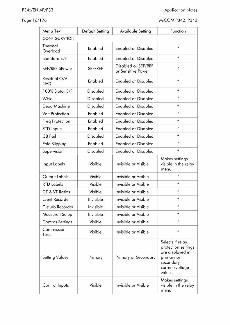
2.1 Configuration column
The P340 relays include a column in the menu called the “CONFIGURATION” column. This affects the operation of each of the individual protection functions. The aim of this column is to allow general configuration of the relay from a single point in the menu. Any of the functions that are disabled or made invisible from this column do not then appear within the main relay menu.
The following table shows the relay menu for the configuration column, with default settings. The brief description of the function of each setting is also provided.
Menu Text Default Setting Available Setting Function
CONFIGURATION
Restore Defaults No Operation
No Operation All Settings Setting Group 1 Setting Group 2 Setting Group 3 Setting Group 4
Restore default settings to any or all group of settings
Application Notes P34x/EN AP/F33
MiCOM P342, P343 Page 15/176
Menu Text Default Setting Available Setting Function
CONFIGURATION
Setting Group Select via Menu Select via Menu Select via Optos
Change setting groups by?
Active Settings Group 1
Group 1 Group 2 Group 3 Group 4
Select active setting group used for protection settings
Save Changes No Operation No Operation Save Abort
Saves all setting changes from buffer memory into stored settings
Copy From Group 1 Group1, 2, 3 or 4
Selects a group of settings to copy to the group designated in “Copy to” cell
Copy To No Operation Group1,2,3 or 4
Copies the group of settings selected in the “Copy from” cell to the selected setting group
Setting Group 1 Enabled Enabled or Disabled
Selects if Group 1 settings are available on the relay
Setting Group 2 Disabled Enabled or Disabled
Selects if Group 2 settings are available on the relay
Setting Group 3 Disabled Enabled or Disabled
Selects if Group 3 settings are available on the relay
Setting Group 4 Disabled Enabled or Disabled
Selects if Group 4 settings are available on the relay
Gen Differential Enabled Enabled or Disabled Enables protection element in the relay
Power Enabled Enabled or Disabled “
Field Failure Enabled Enabled or Disabled “
NPS Thermal Enabled Enabled or Disabled “
System Backup Enabled Enabled or Disabled “
Overcurrent Enabled Enabled or Disabled “
P34x/EN AP/F33 Application Notes
Page 16/176 MiCOM P342, P343
Menu Text Default Setting Available Setting Function
CONFIGURATION
Thermal Overload Enabled Enabled or Disabled “
Standard E/F Enabled Enabled or Disabled “
SEF/REF SPower SEF/REF Disabled or SEF/REF or Sensitive Power “
Residual O/V NVD Enabled Enabled or Disabled “
100% Stator E/F Disabled Enabled or Disabled “
V/Hz Disabled Enabled or Disabled “
Dead Machine Disabled Enabled or Disabled “
Volt Protection Enabled Enabled or Disabled “
Freq Protection Enabled Enabled or Disabled “
RTD Inputs Enabled Enabled or Disabled “
CB Fail Disabled Enabled or Disabled “
Pole Slipping Enabled Enabled or Disabled “
Supervision Disabled Enabled or Disabled “
Input Labels Visible Invisible or Visible Makes settings visible in the relay menu
Output Labels Visible Invisible or Visible “
RTD Labels Visible Invisible or Visible “
CT & VT Ratios Visible Invisible or Visible “
Event Recorder Invisible Invisible or Visible “
Disturb Recorder Invisible Invisible or Visible “
Measure’t Setup Invisible Invisible or Visible “
Comms Settings Visible Invisible or Visible “
Commission Tests Visible Invisible or Visible “
Setting Values Primary Primary or Secondary
Selects if relay protection settings are displayed in primary or secondary current/voltage values
Control Inputs Visible Invisible or Visible Makes settings visible in the relay menu
Application Notes P34x/EN AP/F33
MiCOM P342, P343 Page 17/176
Menu Text Default Setting Available Setting Function
CONFIGURATION
CLIO Inputs Enabled Enabled or Disabled Enables protection element in the relay
CLIO Outputs Enabled Enabled or Disabled “
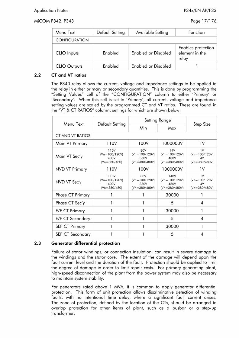
2.2 CT and VT ratios
The P340 relay allows the current, voltage and impedance settings to be applied to the relay in either primary or secondary quantities. This is done by programming the “Setting Values” cell of the “CONFIGURATION” column to either ‘Primary’ or ‘Secondary’. When this cell is set to ‘Primary’, all current, voltage and impedance setting values are scaled by the programmed CT and VT ratios. These are found in the “VT & CT RATIOS” column, settings for which are shown below.
Menu Text Default Setting Setting Range
Step Size Min Max
CT AND VT RATIOS
Main VT Primary 110V 100V 1000000V 1V
Main VT Sec’y 110V
(Vn=100/120V) 400V
(Vn=380/480)
80V (Vn=100/120V)
360V (Vn=380/480V)
14V (Vn=100/120V)
480V (Vn=380/480V)
1V (Vn=100/120V)
4V (Vn=380/480V)
NVD VT Primary 110V 100V 1000000V 1V
NVD VT Sec'y 110V
(Vn=100/120V) 400V
(Vn=380/480)
80V (Vn=100/120V)
360V (Vn=380/480V)
140V (Vn=100/120V)
480V (Vn=380/480V)
1V (Vn=100/120V)
4V (Vn=380/480V)
Phase CT Primary 1 1 30000 1
Phase CT Sec’y 1 1 5 4
E/F CT Primary 1 1 30000 1
E/F CT Secondary 1 1 5 4
SEF CT Primary 1 1 30000 1
SEF CT Secondary 1 1 5 4
2.3 Generator differential protection
Failure of stator windings, or connection insulation, can result in severe damage to the windings and the stator core. The extent of the damage will depend upon the fault current level and the duration of the fault. Protection should be applied to limit the degree of damage in order to limit repair costs. For primary generating plant, high-speed disconnection of the plant from the power system may also be necessary to maintain system stability.
For generators rated above 1 MVA, it is common to apply generator differential protection. This form of unit protection allows discriminative detection of winding faults, with no intentional time delay, where a significant fault current arises. The zone of protection, defined by the location of the CTs, should be arranged to overlap protection for other items of plant, such as a busbar or a step-up transformer.

P34x/EN AP/F33 Application Notes
Page 18/176 MiCOM P342, P343
Circulating current differential protection operates on the principle that current entering and leaving a zone of protection will be equal. Any difference between these currents is indicative of a fault being present in the zone. If CTs are connected as shown in Figure 1 it can be seen that current flowing through the zone of protection will cause current to circulate around the secondary wiring. If the CTs are of the same ratio and have identical magnetising characteristics they will produce identical secondary currents and hence zero current will flow through the relay. If a fault exists within the zone of protection there will be a difference between the output from each CT; this difference flowing through the relay causing it to operate.
Figure 1: Principle of circulating current differential protection
Heavy through current, arising from an external fault condition, can cause one CT to saturate more than the other, resulting in a difference between the secondary current produced by each CT. It is essential to stabilise the protection for these conditions. Two methods are commonly used. A biasing technique, where the relay setting is raised as through current increases. Alternatively, a high impedance technique, where the relay impedance is such that under maximum through fault conditions, the current in the differential element is insufficient for the relay to operate.
The generator differential protection function available in the P343 relay can be used in either biased differential or high impedance differential mode. Both modes of operation are equally valid; users may have a preference for one over the other. The operating principle of each is described in the following sections.
The generator differential protection may also be used for interturn protection which is described in the following sections.
A DDB (Digital Data Bus) signal is available to indicate the tripping of each phase of differential protection (DDB 419, DDB 420, DDB 421), in addition a 3 phase trip DDB signal is provided (DDB 418). These signals are used to operate the output relays and trigger the disturbance recorder as programmed into the Programmable Scheme Logic (PSL). The state of the DDB signals can also be programmed to be viewed in the “Monitor Bit x” cells of the “COMMISSION TESTS” column in the relay.
The following table shows the relay menu for the Differential protection element, including the available setting ranges and factory defaults:

Application Notes P34x/EN AP/F33
MiCOM P342, P343 Page 19/176
Menu Text Default Setting Setting Range
Step Size Min Max
GROUP 1 GEN DIFF
GenDiff Function Biased Disabled, Biased, High Impedance, Interturn N/A
Gen Diff Ιs1 0.1 0.05 Ιn A 0.5 Ιn A 0.01 Ιn A
Gen Diff k1 0 0 20% 5%
Gen Diff Ιs2 1.5 1.0 Ιn A 5.0 Ιn A 0.1 Ιn A
Gen Diff k2 150 20% 150% 10%
Interturn Is_A 0.1 0.05 Ιn A 2 Ιn A 0.01 Ιn A
Interturn Is_B 0.1 0.05 Ιn A 2 Ιn A 0.01 Ιn A
Interturn Is_C 0.1 0.05 Ιn A 2 Ιn A 0.01 Ιn A
Interturn ITimeDelay 0.1 s 0 s 100 s 0.01 s
2.3.1 Biased differential protection
In a biased differential relay, the through current is used to increase the setting of the differential element. For heavy through faults, it is unlikely that the CT outputs at each zone end will be identical, due to the effects of CT saturation. In this case a differential current can be produced. However, the biasing will increase the relay setting, such that the differential spill current is insufficient to operate the relay.
The through current is calculated as the average of the scalar sum of the current entering and leaving the zone of protection. This calculated through current is then used to apply a percentage bias to increase the differential setting. The percentage bias can be varied to give the operating characteristic shown in Figure 2.
Figure 2: Biased differential protection operating characteristic

P34x/EN AP/F33 Application Notes
Page 20/176 MiCOM P342, P343
Two bias settings are provided in the P343 relay. The initial bias slope, “Gen Diff k1”, is applied for through currents upto “G en DiffΙs2”. The second bias slope, “Gen Diff k2”, is applied for through currents above the "Gen Diff Ιs2" setting.
The operating current of the biased differential element, for any value of through current, can be calculated using the following formulae:
Ι1 + Ι2ΙBIAS = 2
ΙDIFF > K2.ΙBIAS – (K2 – K1) Ιs2 + Ιs1 where ΙBIAS > Ιs2
ΙDIFF > K1.ΙBIAS + Ιs1 where ΙBIAS ™Ιs2
The Biased differential protection function uses the two sets of three phase current measurement inputs (ΙA, ΙB, ΙC, ΙA2, ΙB2, ΙC2), connected to measure the phase current at the neutral end and terminals of the machine, as shown in Figure 3. The bias and differential currents are calculated by the relay software, providing a phase segregated differential protection function, and may be viewed in the “MEASUREMENTS” columns in the relay menu.
Figure 3: Relay connections for biased differential protection
2.3.2 Setting guidelines for biased differential protection
To select biased differential protection the “GenDiff Function” cell should be set to ‘Biased’.
The differential current setting, “Gen Diff Ιs1”, should be set to a low setting to protect as much of the machine winding as possible. A setting of 5% of rated current of the machine is generally considered to be adequate. “Gen Diff Ιs2”,the threshold above which the second bias setting is applied, should be set to 120% of the machine rated current.
The initial bias slope setting, “Gen Diff k1”, should be set to 0% to provide optimum sensitivity for internal faults. The second bias slope may typically be set to 150% to provide adequate stability for external faults.

Application Notes P34x/EN AP/F33
MiCOM P342, P343 Page 21/176
These settings may be increased where low accuracy class CTs are used to supply the protection.
2.3.3 High impedance differential protection
The high impedance principle is best explained by considering a differential scheme where one CT is saturated for an external fault, as shown in Figure 4.
Figure 4: Principle of high impedance differential protection
If the relay circuit is considered to be a very high impedance, the secondary current produced by the healthy CT will flow through the saturated CT. If the magnetising impedance of the saturated CT is considered to be negligible, the maximum voltage across the relay circuit will be equal to the secondary fault current multiplied by the connected impedance, (RL3 + RL4 + RCT2).
The relay can be made stable for this maximum applied voltage by increasing the overall impedance of the relay circuit, such that the resulting current through the relay is less than its current setting. As the impedance of the relay input alone is relatively low, a series connected external resistor is required. The value of this resistor, RST, is calculated by the formula shown in Figure 4. An additional non linear resistor, metrosil, may be required to limit the peak secondary circuit voltage during internal fault conditions.

P34x/EN AP/F33 Application Notes
Page 22/176 MiCOM P342, P343
To ensure that the protection will operate quickly during an internal fault the CTs used to operate the protection must have a kneepoint voltage of at least 2Vs.
The high impedance differential protection function uses the ΙA2, ΙB2, ΙC2 current inputs connected to measure the differential current in each phase, as shown in Figure 5.
Figure 5: Relay connections for high impedance differential protection
2.3.4 Setting guidelines for high impedance differential protection
To select high impedance differential protection the “GenDiff Function” cell should be set to ‘High Impedance’.
The differential current setting, “G en Diff Ιs1”, should be set to a low setting to protect as much of the machine winding as possible. A setting of 5% of rated current of the machine is generally considered to be adequate. This setting may need to be increased where low accuracy class CTs are used to supply the protection. A check should be made to ensure that the primary operating current of the element is less than the minimum fault current for which the protection should operate.
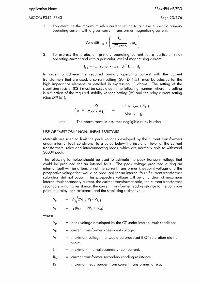
The primary operating current (Ιop) will be a function of the current transformer ratio, the relay operating current (Gen Diff Ιs1), the number of current transformers in parallel with a relay element (n) and the magnetising current of each current transformer (Ιe) at the stability voltage (Vs). This relationship can be expressed in three ways:
1. To determine the maximum current transformer magnetising current to achieve a specific primary operating current with a particular relay operating current.
1 Ιop Ι < xe - Gen diff REF > Ιs1n CT ratio
Application Notes P34x/EN AP/F33
MiCOM P342, P343 Page 23/176
2. To determine the maximum relay current setting to achieve a specific primary operating current with a given current transformer magnetising current.
Ιop Gen diff Ιs1 < - nΙ
CT ratio e
3. To express the protection primary operating current for a particular relay operating current and with a particular level of magnetising current.
Ιop = (CT ratio) x (Gen diff Ιs1 + nΙe)
In order to achieve the required primary operating current with the current transformers that are used, a current setting (Gen Diff Ιs1) must be selected for the high impedance element, as detailed in expression (ii) above. The setting of the stabilising resistor (RST) must be calculated in the following manner, where the setting is a function of the required stability voltage setting (Vs) and the relay current setting (Gen Diff Ιs1).
Vs 1.5 ΙF (RCT + 2RL) = =RST Gen diff Ιs1 Gen diff Ιs1
Note: The above formula assumes negligible relay burden
USE OF “METROSIL” NON-LINEAR RESISTORS
Metrosils are used to limit the peak voltage developed by the current transformers under internal fault conditions, to a value below the insulation level of the current transformers, relay and interconnecting leads, which are normally able to withstand 3000V peak.
The following formulae should be used to estimate the peak transient voltage that could be produced for an internal fault. The peak voltage produced during an internal fault will be a function of the current transformer kneepoint voltage and the prospective voltage that would be produced for an internal fault if current transformer saturation did not occur. This prospective voltage will be a function of maximum internal fault secondary current, the current transformer ratio, the current transformer secondary winding resistance, the current transformer lead resistance to the common point, the relay lead resistance and the stabilising resistor value.
Vp = 2 2Vk ( Vf - Vk )
Vf = Ι'f (RCT + 2RL + RST)
where
Vp = peak voltage developed by the CT under internal fault conditions.
Vk = current transformer knee-point voltage.
Vf = maximum voltage that would be produced if CT saturation did not occur.
Ι‘f = maximum internal secondary fault current.
RCT = current transformer secondary winding resistance.
RL = maximum lead burden from current transformer to relay.
P34x/EN AP/F33 Application Notes
Page 24/176 MiCOM P342, P343
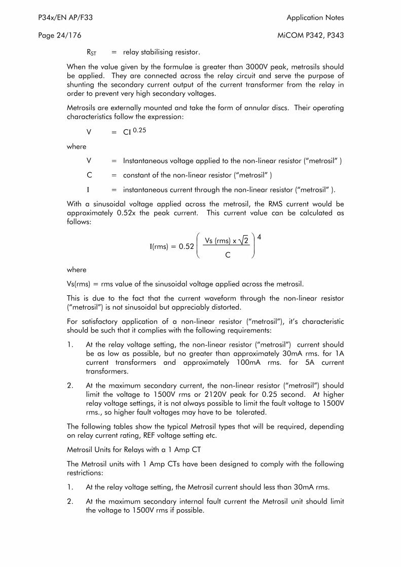
RST = relay stabilising resistor.
When the value given by the formulae is greater than 3000V peak, metrosils should be applied. They are connected across the relay circuit and serve the purpose of shunting the secondary current output of the current transformer from the relay in order to prevent very high secondary voltages.
Metrosils are externally mounted and take the form of annular discs. Their operating characteristics follow the expression:
V = CΙ 0.25
where
V = Instantaneous voltage applied to the non-linear resistor (“metrosil” )
C = constant of the non-linear resistor (“metrosil” )
Ι = instantaneous current through the non-linear resistor (“metrosil” ).
With a sinusoidal voltage applied across the metrosil, the RMS current would be approximately 0.52x the peak current. This current value can be calculated as follows:
Ι(rms) = 0.52 Vs (rms) x 2
C
4
where
Vs(rms) = rms value of the sinusoidal voltage applied across the metrosil.
This is due to the fact that the current waveform through the non-linear resistor (“metrosil”) is not sinusoidal but appreciably distorted.
For satisfactory application of a non-linear resistor (“metrosil”), it’s characteristic should be such that it complies with the following requirements:
1. At the relay voltage setting, the non-linear resistor (“metrosil”) current should be as low as possible, but no greater than approximately 30mA rms. for 1A current transformers and approximately 100mA rms. for 5A current transformers.
2. At the maximum secondary current, the non-linear resistor (“metrosil”) should limit the voltage to 1500V rms or 2120V peak for 0.25 second. At higher relay voltage settings, it is not always possible to limit the fault voltage to 1500V rms., so higher fault voltages may have to be tolerated.
The following tables show the typical Metrosil types that will be required, depending on relay current rating, REF voltage setting etc.
Metrosil Units for Relays with a 1 Amp CT
The Metrosil units with 1 Amp CTs have been designed to comply with the following restrictions:
1. At the relay voltage setting, the Metrosil current should less than 30mA rms.
2. At the maximum secondary internal fault current the Metrosil unit should limit the voltage to 1500V rms if possible.
Application Notes P34x/EN AP/F33
MiCOM P342, P343 Page 25/176
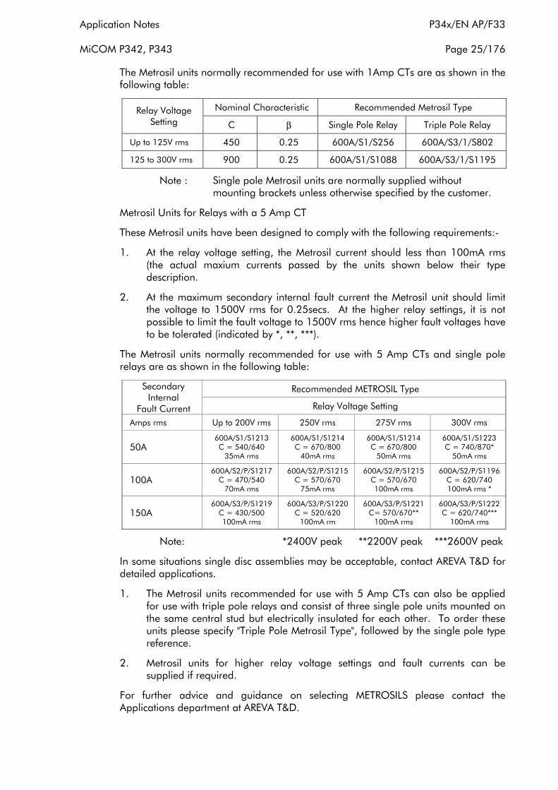
The Metrosil units normally recommended for use with 1Amp CTs are as shown in the following table:
Relay Voltage Nominal Characteristic Recommended Metrosil Type
Setting C β Single Pole Relay Triple Pole Relay
Up to 125V rms 450 0.25 600A/S1/S256 600A/S3/1/S802
125 to 300V rms 900 0.25 600A/S1/S1088 600A/S3/1/S1195
Note : Single pole Metrosil units are normally supplied without mounting brackets unless otherwise specified by the customer.
Metrosil Units for Relays with a 5 Amp CT
These Metrosil units have been designed to comply with the following requirements:
1. At the relay voltage setting, the Metrosil current should less than 100mA rms (the actual maxium currents passed by the units shown below their type description.
2. At the maximum secondary internal fault current the Metrosil unit should limit the voltage to 1500V rms for 0.25secs. At the higher relay settings, it is not possible to limit the fault voltage to 1500V rms hence higher fault voltages have to be tolerated (indicated by *, **, ***).
The Metrosil units normally recommended for use with 5 Amp CTs and single pole relays are as shown in the following table:
Secondary Internal
Fault Current
Recommended METROSIL Type
Relay Voltage Setting
Amps rms Up to 200V rms 250V rms 275V rms 300V rms
50A 600A/S1/S1213 C = 540/640
35mA rms
600A/S1/S1214 C = 670/800
40mA rms
600A/S1/S1214 C = 670/800
50mA rms
600A/S1/S1223 C = 740/870*
50mA rms
100A 600A/S2/P/S1217
C = 470/540 70mA rms
600A/S2/P/S1215 C = 570/670
75mA rms
600A/S2/P/S1215 C = 570/670 100mA rms
600A/S2/P/S1196 C = 620/740 100mA rms *
150A 600A/S3/P/S1219
C = 430/500 100mA rms
600A/S3/P/S1220 C = 520/620
100mA rm
600A/S3/P/S1221 C= 570/670**
100mA rms
600A/S3/P/S1222 C = 620/740***
100mA rms
Note: *2400V peak **2200V peak ***2600V peak
In some situations single disc assemblies may be acceptable, contact AREVA T&D for detailed applications.
1. The Metrosil units recommended for use with 5 Amp CTs can also be applied for use with triple pole relays and consist of three single pole units mounted on the same central stud but electrically insulated for each other. To order these units please specify "Triple Pole Metrosil Type", followed by the single pole type reference.
2. Metrosil units for higher relay voltage settings and fault currents can be supplied if required.
For further advice and guidance on selecting METROSILS please contact the Applications department at AREVA T&D.
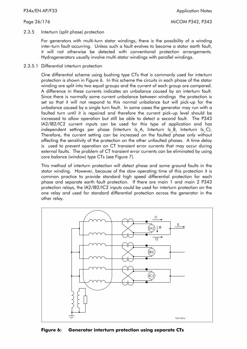
P34x/EN AP/F33 Application Notes
Page 26/176 MiCOM P342, P343
2.3.5 Interturn (split phase) protection
For generators with multi-turn stator windings, there is the possibility of a winding inter-turn fault occurring. Unless such a fault evolves to become a stator earth fault, it will not otherwise be detected with conventional protection arrangements. Hydrogenerators usually involve multi-stator windings with parallel windings.
2.3.5.1 Differential interturn protection
One differential scheme using bushing type CTs that is commonly used for interturn protection is shown in Figure 6. In this scheme the circuits in each phase of the stator winding are split into two equal groups and the current of each group are compared. A difference in these currents indicates an unbalance caused by an interturn fault. Since there is normally some current unbalance between windings the protection is set so that it will not respond to this normal unbalance but will pick-up for the unbalance caused by a single turn fault. In some cases the generator may run with a faulted turn until it is repaired and therefore the current pick-up level should be increased to allow operation but still be able to detect a second fault. The P343 IA2/IB2/IC2 current inputs can be used for this type of application and has independent settings per phase (Interturn Is_A, Interturn Is_B, Interturn Is_C). Therefore, the current setting can be increased on the faulted phase only without affecting the sensitivity of the protection on the other unfaulted phases. A time delay is used to prevent operation on CT transient error currents that may occur during external faults. The problem of CT transient error currents can be eliminated by using core balance (window) type CTs (see Figure 7).
This method of interturn protection will detect phase and some ground faults in the stator winding. However, because of the slow operating time of this protection it is common practice to provide standard high speed differential protection for each phase and separate earth fault protection. If there are main 1 and main 2 P343 protection relays, the IA2/IB2/IC2 inputs could be used for interturn protection on the one relay and used for standard differential protection across the generator in the other relay.
Figure 6: Generator interturn protection using separate CTs

Application Notes P34x/EN AP/F33
MiCOM P342, P343 Page 27/176
Figure 7: Generator interturn protection using core balance (window) CTs
2.3.5.1.1 Setting guidelines for differential interturn protection To select interturn differential protection the “GenDiff Function” cell should be set to ‘Interturn’.
The differential current settings, “Interturn Ιs_A,Interturn Ιs_B,Interturn Ιs_C”,should be set to a low setting to protect as much of the machine winding as possible. A setting of 5% of rated current of the machine is generally considered to be adequate. This setting may need to be increased where low accuracy class CTs are used to supply the protection.
The time delay setting “Interturn ΙTim eDelay” should be set to prevent operation on CT transient error currents that may occur during external faults. A typical time setting would be 0.1s.
2.3.5.2 Application of biased differential protection for interturn protection
For inter-turn protection applications where the generator stator is wound with 2 or more identical 3 phase windings connected in parallel, provided the windings are brought out separately, biased differential protection can be used connected to CTs in the line ends of the 2 or more windings, see Figure 8. In this type of application a biased system should always be used as it is not possible to guarantee in advance that exact current sharing between the windings will take place. A small error in this sharing current would produce instability in an unbiased system at high levels of through fault current. Balanced current in the two windings produces a circulation of current in the current transformer secondary circuit, but any in zone fault, including an interturn fault, will result in a circulation of current between the windings producing an output in the relay operating circuit.

P34x/EN AP/F33 Application Notes
Page 28/176 MiCOM P342, P343
Note, the biased differential protection in the P343 uses both sets of 3 phase current inputs and so if the P343 differential protection was used for inter-turn protection no other protection function in the P343 would be available. As normally differential protection plus the many other protection functions in the P343 are required for the generator protection in addition to the interturn protection it is advisable to use a separate biased differential relay for the interturn protection in this application.
Another scheme that could be used on this type of generator is shown in Figure 9. This arrangement is an attempt to get the benefits of inter-turn and differential protection with a saving in CTs and relays. However, this arrangement is not as sensitive as other schemes using separate inter-turn relays or differential relays. The scheme in Figure 9 requires the neutral end CTs having half the turns ratio of the terminal end CTs. The sensitivity of the protection for inter-turn faults is limited by the fact that the two CT ratios applied must be selected in accordance with the generator rated current. A P343 could be used for this application with the IA/IB/IC inputs connected to the terminal side CTs as these see the full rated current. Note, the IA/IB/IC inputs feed the current, impedance and power based protection. However, in the case of a single generator feeding an isolated system, back-up protection should use CTs at the neutral end of the machine to ensure internal faults on the generator windings are detected. Thus, for this type of application it is advised that a separate biased differential protection is used for the inter-turn protection. A P342 from separate CTs at the neutral end of the generator could then be used for the rest of the protection.
Figure 8: Transverse biased differential protection for double wound machines

Application Notes P34x/EN AP/F33
MiCOM P342, P343 Page 29/176
Figure 9: Generator differential and interturn protection
2.3.5.3 Application of overcurrent protection for interturn protection
Another method that could be used for inter-turn protection is to use the current operated stator earth fault protection function using an additional single CT as shown in Figure 10. In this application the neutral voltage displacement protection (59N) would act as the main stator earth fault protection even though the current based stator earth fault protection could still respond to some stator earth fault conditions. This form of interturn fault protection, using the 51N stator earth fault current operated element (IN>1/2 or ISEF>1) offers the possibility of greater sensitivity compared to the technique shown in Figure 9. This is due to the fact that the required ratio of the single CT for this application is arbitrary. The current setting of the main current operated element (IN>1/2 or ISEF>1) should be set in accordance with the selected CT ratio to provide adequate primary sensitivity for the minimum interturn fault current. For similar reasons the time delay applied should be set similar to that recommended for applications of the main current operated element of normal stator earth fault protection.

P34x/EN AP/F33 Application Notes
Page 30/176 MiCOM P342, P343
Figure 10: Overcurrent interturn protection
2.3.5.4 Interturn protection by zero sequence voltage measurement
Interturn faults in a generator with a single winding can be detected by observing the zero sequence voltage across the machine. Normally, no zero sequence voltage should exist but a short circuit of one or more turns on one phase will cause the generated e.m.f. to contain some zero sequence component. This method of interturn protection can be provided using the neutral voltage displacement protection in the P342/3, see section 2.14.
External earth faults will also produce a zero sequence voltage on a directly connected generator. Most of the voltage will be dropped across the earthing resistor, the drop on the generator being small and the zero sequence component being limited to one or two percent. It is preferable, therefore, to measure the voltage drop across the winding, rather than the zero sequence voltage to earth at the line terminals. This can be done using a voltage transformer connected to the line side of the generator, with the neutral point of the primary winding connected to the generator neutral, above the earthing resistor or earthing transformer. This arrangement is shown in Figure 11. The zero sequence voltage can be measured directly from the voltage transformer broken delta winding connected to the neutral voltage input, Vn, on the P342/3. Alternatively, the zero sequence voltage can be derived from the 3 phase voltage inputs, VA, VB, VC, to the relay.
The 3rd harmonic component of the emf may be larger than the required setting, however, there is no danger of maloperation as the 3rd harmonic component is filtered by the relay’s Fourier filter.
With a direct-connected machine it is still possible that a close up earth fault will produce a zero sequence voltage drop greater than that produced by the short circuiting of one turn. It is therefore necessary to apply a short time delay to the tripping element. With a generator-transformer unit an external earth fault can not

Application Notes P34x/EN AP/F33
MiCOM P342, P343 Page 31/176
draw zero sequence current through the delta winding of the transformer. Therefore, no residual voltage will be produced from the voltage transformer and so no time delay is required in this case for the trip element.
With this type of VT connection the zero sequence voltage from the VT is small for an external fault. Also, the output from the star connected secondary winding of the VT will not be able to correctly represent phase-ground voltages (for external faults), only phase-phase voltages will remain accurate. Therefore, the sensitive directional earth fault protection and CT supervision element, which use zero sequence voltage, may not operate and so should be disabled. The under and over voltage protection can be set as phase-to-phase measurement with this type of VT connection. The underimpedance and the voltage dependent overcurrent use phase-phase voltages anyway, therefore the accuracy should not be affected. The protection functions which use phase-neutral voltages are the power, the loss of excitation and pole slipping protection; all are for detecting abnormal generator operation under 3phase balanced conditions, therefore the accuracy of these protection functions should not be affected.
If the neutral voltage displacement element is required for 95% stator earth fault protection as well as interturn protection a separate VT connection at the terminals of the generator or a distribution transformer at the generator earth is required to obtain the correct zero sequence voltage. Note, the neutral voltage displacement protection in the P342/3 relay can use the measured residual voltage from the Vn input or the derived residual voltage from the 3 phase voltage inputs but not both. So, if the derived residual voltage is used for interturn protection as shown in Figure 11, then the measured residual voltage from a distribution transformer at the generator neutral point can not be used for 95% stator earth fault protection using one relay. See section 2.14 for more information on the P342/3 neutral voltage displacement protection.
Figure 11: Interturn protection by zero sequence voltage measurement

P34x/EN AP/F33 Application Notes
Page 32/176 MiCOM P342, P343
2.4 Phase fault overcurrent protection
A two stage non directional overcurrent element is provided in the P340 relays. This element can be used to provide time delayed back-up protection for the system and high set protection providing fast operation for machine faults.
The first stage has a time delayed characteristic that can be set as either Inverse Definite Minimum Time (IDMT) or Definite Time (DT). The second stage has a definite time delay, which can be set to zero to produce instantaneous operation. Each stage can be selectively enabled or disabled.
This element uses the ΙA, ΙB, and ΙC relay inputs and can be fed from CTs at the terminal or neutral end of the generator, depending on the application.
Each stage can be blocked by energising the relevant DDB signal via the PSL (DDB 354, DDB 355). DDB signals are also available to indicate the start and trip of each phase of each stage of protection, (Starts: DDB 597-604, Trips: DDB 477-484). The state of the DDB signals can be programmed to be viewed in the “Monitor Bit x” cells of the “COMMISSION TESTS” column in the relay.
Setting ranges for this element are shown in the following table:
Menu Text Default Setting Setting Range
Step Size Min Max
GROUP 1: OVERCURRENT
Ι>1 Function Disabled
Disabled, DT, IEC S Inverse, IEC V Inverse, IEC E Inverse,
UK LT Inverse, UK Rectifier, RI, IEEE M Inverse, IEEE V Inverse, IEEE E Inverse,
US Inverse, US ST Inverse
Ι>1 Current Set 1 x Ιn A 0.08 x Ιn A 4 x Ιn A 0.01 x Ιn A
Ι>1 Time Delay 1 s 0 100 s 0.01 s
Ι>1 TMS 1 0.025 1.2 0.025
Ι>1 Time Dial 1 0.01 100 0.01
Ι>1 K(RI) 1 0.1 10 0.05
Ι>1 Reset Char DT DT or Inverse N/A
Ι>1 tRESET 0 s 0 s 100 s 0.01s
Ι>2 Function DT Disabled or DT N/A
Ι>2 Current Set 0.08 x Ιn A 0.08 x Ιn A 10 x Ιn A 0.01 x Ιn A
Ι>2 Time Delay 0 s 0 s 100 s 0.01 s
For inverse time delayed characteristics, the following options are available. Note that all IDMT curves conform to the following formula:
IEC Curves
t = T x K
+ L (Ι/Ιs)
α - 1

Application Notes P34x/EN AP/F33
MiCOM P342, P343 Page 33/176
IEEE Curves
K t = TD x
K = constant
α = constant
+ L
operation time t =
Ι measured current =
Ι current threshold setting s =
L ANSI/IEEE constant (zero for IEC curves) =
T Time multiplier setting =
TD Time dial setting for IEEE curves =
(Ι/Ιs) α - 1
Curve Description Standard K constant α constant L constant
Standard Inverse IEC 0.14 0.02 0
Very Inverse IEC 13.5 1 0
Extremely Inverse IEC 80 2 0
Long Time Inverse UK 120 1 0
Rectifier UK 45900 5.6 0
Moderately Inverse IEEE 0.0515 0.02 0.114
Very Inverse IEEE 19.61 2 0.491
Extremely Inverse IEEE 28.2 2 0.1217
Inverse US 5.95 2 0.18
Short Time Inverse US 0.16758 0.02 0.11858
Note that the IEEE and US curves are set differently to the IEC/UK curves, with regard to the time setting. A time multiplier setting (TMS) is used to adjust the operating time of the IEC curves, whereas a time dial setting is employed for the IEEE/US curves. Both the TMS and Time Dial settings act as multipliers on the basic characteristics but the scaling of the time dial is approximately 10 times that of the TMS, as shown in the previous menu. The menu is arranged such that if an IEC/UK curve is selected, the “Ι>1 Time Dial” cell is not visible and vice versa for the TMS setting. The UK rectifier curve is not required for generator protection applications but it is included for consistency with other MiCOM products which use overcurrent protection.
Note, that the IEC/UK inverse characteristics can be used with a definite time reset characteristic, however, the IEEE/US curves may have an inverse or definite time reset characteristic. The following equation can be used to calculate the inverse reset time for IEEE/US curves:
TD x S tRESET = in seconds (1 - M2)

P34x/EN AP/F33 Application Notes
Page 34/176 MiCOM P342, P343
where:
TD = Time dial setting for IEEE curves
S = Constant
M = Ι / Ιs
Curve Description Standard S Constant
Moderately Inverse IEEE 4.85
Very Inverse IEEE 21.6
Extremely Inverse IEEE 29.1
Inverse US 5.95
Short Time Inverse US 2.261
2.4.1 RI curve
The RI curve (electromechanical) has been included in the first stage characteristic setting options for Phase Overcurrent and Earth Fault protections. The curve is represented by the following equation:
t = K x 0.339 -
1
0.236/M in seconds
With K adjustable from 0.1 to 10 in steps of 0.05
M = Ι / Ιs
2.4.2 Application of timer hold facility
The first stage of overcurrent protection in the P340 relays are provided with a timer hold facility.
Setting the hold timer to zero means that the overcurrent timer for that stage will reset instantaneously once the current falls below 95% of the current setting. Setting the hold timer to a value other than zero, delays the resetting of the protection element timers for this period. This may be useful in certain applications, for example when grading with electromechanical overcurrent relays which have inherent reset time
delays. It will also enable the element to become sensitive to a pole slipping condition where the element will cyclically operate as the machine slips successive poles.
If an IEC inverse or DT operating characteristic is chosen for, this time delay is set via the “Ι>1 tRESET” setting.
If an IEEE/US operate curve is selected, the reset characteristic may be set to either definite time or inverse time as selected in cell “Ι>1 Reset Char”. If definite time (‘DT’) is selected the “Ι>1 tRESET” cell may be used to set the time delay. If inverse time reset (‘Inverse’) is selected the reset time will follow the inverse time operating characteristic, modified by the time dial setting, selected for “Ι>1 Function”.
Another situation where the timer hold facility may be used to reduce fault clearance times is where intermittent faults may be experienced. When the reset time of the overcurrent relay is instantaneous the relay will be repeatedly reset and not be able to trip until the fault becomes permanent. By using the timer hold facility the relay will integrate the fault current pulses, thereby reducing fault clearance time.
Application Notes P34x/EN AP/F33
MiCOM P342, P343 Page 35/176
2.4.3 Setting guidelines for overcurrent protection
The first stage of overcurrent protection can be selected by setting “Ι>1 Function” to any of the inverse or DT settings. The first stage is disabled if “Ι>1 Function” is set to ‘Disabled’.
The first stage can provide back-up protection for faults on the generator and the system. As such it should be co-ordinated with downstream protection to provide discrimination for system faults, setting the current threshold (“I>1 Current Set”), and the time delay.
“Ι>1 TMS” – for IEC curves;
“Ι>1 Time Dial” – for US/IEEE curves;
“Ι>1 Time Delay” – for definite time accordingly.
In order to provide back-up protection for the generator and system, the element must be supplied from CTs connected in the generator tails. If terminal end CTs are used, the element will provide protection for the system only, unless the generator is connected in parallel to a second source of supply.
The second stage of overcurrent protection can be enabled by setting “Ι>2 Function” to DT, providing a definite time operating characteristic. The second stage is disabled if “Ι>2 Function” is set to ‘Disabled’. Where terminal CTs are used, the second stage can be set as an instantaneous overcurrent protection, providing protection against internal faults on the machine. The current setting of the second stage, “Ι>2 Current Set”, could be set to 120% of the maximum fault rating of the generator, typically 8 x full load current. The operating time, “Ι>2 Time Delay”, should be set to 0s to give instantaneous operation. The stage will therefore be stable for external faults where the fault current from the generator will be below the stage current setting. For faults within the machine, the fault current will be supplied from the system and will be above the second stage current setting, resulting in fast clearance of the internal fault.
2.5 System back-up protection
A generator is a source of electrical power and will supply system faults until they are cleared by system protection. Back-up protection must be applied at the generator so that faults are cleared in the event of downstream protection/circuit breakers failing to operate.
The fault current supplied by a generator will vary during a fault condition as indicated by the generator decrement curve, shown in Figure 12. The fault current response is determined by the action of the automatic voltage regulator on the machine. With some generators, fault current initiates an AVR ‘boost’ circuit which maintains the fault current at a relatively high level. If the voltage regulator is set to manual control or no boost circuit exists, the fault current can be severely restricted, leading to slow operation of back-up protection for system faults. In the worst case the fault current will fall below the full load rating of the machine, so simple overcurrent protection with a setting above full load current, cannot operate.

P34x/EN AP/F33 Application Notes
Page 36/176 MiCOM P342, P343
Figure 12: Typical generator fault current decrement curve
System back-up protection must operate quickly during a fault and must not operate for load conditions. To achieve these two objectives, two methods of system back-up protection are commonly used:
1. Voltage dependant overcurrent protection. The presence of a fault is detected by an under voltage element and the relay setting is adjusted accordingly. Voltage dependant overcurrent protection can beoperated in a ‘voltage controlled’ or ‘voltage restrained’ mode.
2. Under impedance protection. This element is set to monitor the system impedance at the terminals of the machine. If the impedance measured falls below a set threshold then the element will operate.
Customer preference will determine the mode of operation. However, subtle application benefits can be claimed for one form of protection over the other in certain circumstances.
A single protection element, that can be configured as either voltage dependant overcurrent or under impedance, is provided in the P340 relay for system back-up protection. The operation of the element is described in the following sections.
The function operates from the phase currents measured by the ΙA, ΙB and ΙC measurement inputs on the relay.
The voltage dependent overcurrent and underimpedance System Backup protection elements can be blocked by energising the relevant DDB signal via the PSL, (VDepOC Timer Block, DDB 352 and UnderZ Timer Block, DDB 353). DDB signals are also available to indicate a 3 phase and per phase start and trip, (Voltage dependent overcurrent Starts: DDB 639-642, Voltage dependent overcurrent Trips: DDB 425428, Underimpedance Starts: DDB 650-657, Underimpedance Trips: DDB 500-507). The state of the DDB signals can be programmed to be viewed in the “Monitor Bit x” cells of the “COMMISSION TESTS” column in the relay.
Setting ranges for this element are shown in the following table:

Application Notes P34x/EN AP/F33
MiCOM P342, P343 Page 37/176
Menu Text Default Setting Setting Range
Step Size Min Max
GROUP 1: SYSTEM BACK-UP
Back-up Function Voltage
Controlled
Disabled, Voltage Controlled, Voltage Restrained, Under Impedance
Vector Rotation None None, Delta-Star N/A
V Dep OC Char IEC S Inverse
DT, IEC S Inverse, IEC V Inverse, IEC E Inverse, UK LT Inverse, UK Rectifier, RI,
IEEE M Inverse, IEEE V Inverse, IEEE E Inverse, US Inverse, US ST Inverse
V Dep OC Ι> Set 1 x Ιn A 0.8 x Ιn A 4 x Ιn A 0.01 x Ιn A
V Dep OC T Dial 1 0.01 100 0.01
V Dep OC Reset DT DT or Inverse N/A
V Dep OC Delay 1 s 0 s 100 s 0.01 s
V Dep OC TMS 1 0.025 1.2 0.025
V Dep OC K(RI) 1 0.1 10 0.05
V Dep OC tRESET 0 s 0 s 100 s 0.01 s
V Dep OC V<1Set
80V (Vn=100/120V)
320 V (Vn=380/480V)
5V (Vn=100/120V)
80V (Vn=380/480V)
120V (Vn=100/120V)
480V (Vn=380/480V)
1V (Vn=100/120V)
4V (Vn=380/480V)
V Dep OC V<2Set
60V (Vn=100/120V)
240V (Vn=380/480V)
5V (Vn=100/120V)
80V (Vn=380/480V)
120V (Vn=100/120V)
480V (Vn=380/480V)
1V (Vn=100/120V)
4V (Vn=380/480V)
V Dep OC k Set 0.25 0.1 1 0.05s
Z<1 Setting
70/ΙnΩ (Vn=100/120V)
120/ΙnΩ (Vn=380/480V)
2/ΙnΩ (Vn=100/120V)
2/ΙnΩ (Vn=380/480V)
120/ΙnΩ (Vn=100/120V)
480/ΙnΩ (Vn=380/480V)
0.5/ΙnΩ (Vn=100/120V)
2/ΙnΩ (Vn=380/480V)
Z<1 Time Delay 5 s 0 s 100 s 0.01 s
Z<1 tRESET 0 s 0 s 100 s 0.01 s
Z< Stage 2 Disabled Disabled, Enabled
Z<2 Setting
70/ΙnΩ (Vn=100/120V)
120/ΙnΩ (Vn=380/480V)
2/ΙnΩ (Vn=100/120V)
2/ΙnΩ (Vn=380/480V)
120/ΙnΩ (Vn=100/120V)
480/ΙnΩ (Vn=380/480V)
0.5/ΙnΩ (Vn=100/120V)
2/ΙnΩ (Vn=380/480V)
Z<2 Time Delay 5 s 0 s 100 s 0.01 s
Z<2 tRESET 0 s 0 s 100 s 0.01 s
For inverse time delayed characteristics refer to the phase overcurrent elements, section 2.4.

P34x/EN AP/F33 Application Notes
Page 38/176 MiCOM P342, P343
2.5.1 Voltage dependant overcurrent protection
The generator terminal voltage will drop during fault conditions and so a voltage measuring element can be used to control the current setting of this element. On detection of a fault the current setting is reduced by a factor K. This ensures faults are cleared in spite of the presence of the generator decrement characteristic. Line voltages are used to control each phase overcurrent element as shown below.
Phase Current Control Voltage
Ιa Vab
Ιb Vbc
Ιc Vca
A single stage, non directional overcurrent element is provided. The element has a time delayed characteristic that can be set as either Inverse Definite Minimum Time (IDMT) or Definite Time (DT). The element can be selectively enabled or disabled and can be blocked via a relay input so that the element can be integrated into a blocked overcurrent protection scheme.
The element can be fed from CTs at the terminal or neutral end of the generator.
If voltage dependant overcurrent operation is selected, the element can be set in one of two modes, voltage controlled overcurrent or voltage restrained overcurrent.
2.5.1.1 Voltage controlled overcurrent protection
In this mode of operation, the under voltage detector is used to produce a step change in the relay current setting (from “V Dep OC Ι> Set” to “V Dep OC k Set” x “V Dep OC Ι> Set”), when voltage falls below the voltage setting, “V Dep OC V>1 Set”. Under load conditions the relay can have a high current setting greater than full load current. Under fault conditions the relay is switched to a more sensitive setting leading to fast fault clearance. The operating characteristic of the current setting when voltage controlled mode is selected is shown in Figure 13.
Figure 13: Modification of current pickup level for voltage controlled overcurrent protection

Application Notes P34x/EN AP/F33
MiCOM P342, P343 Page 39/176
Where the generator is directly connected to a busbar, voltage controlled overcurrent protection may be preferred.Setting guidelines for voltage controlled overcurrent function
Voltage controlled overcurrent protection can be selected by setting “Backup Function” to ‘Voltage controlled’. The protection is disabled if “Backup Function” is set to ‘Disabled’.
The current setting, “V Dep OC Ι> Set”, should be set to have a primary operating value in excess of the maximum generator load current.
The current setting multiplying factor, “V Dep OC k Set”, governs the protection function setting under low voltage conditions. This should be set to give a primary operating current less than 50% of the minimum steady-state fault current for a multi-phase fault at the remote end of a feeder, with the generator being the only source. This ensures the element will provide adequate back-up protection for an uncleared fault on that feeder.
The voltage-controlled protection fault characteristic should co-ordinate with outgoing feeder protection for a feeder fault under minimum plant conditions. The operating characteristic, “V Dep OC Char” and the time delay (“V Dep OC TMS” – for IEC curves; “V Dep OC T Dial” – for US/IEEE curves; “V Dep OC Delay” for definite time) should be selected accordingly.
Where parallel sources are present, a remote feeder fault may not result in a sufficient voltage reduction to enable the fault characteristic. For such applications a time undervoltage element can be used to clear the fault (see section 2.6). Alternatively, negative sequence thermal protection could be used (see section 2.11).
The voltage setting for switching between load and fault characteristics, “V Dep OC V<1 Set”, should be greater than the terminal voltage for a fault where back-up protection is required. On a solidly earthed system the element can be made insensitive to earth faults by ensuring that the voltage setting is below 57%Vn (minimum phase to phase voltage for a single phase to earth fault). A typical setting would be 30%Vn. A voltage setting higher than 57%Vn will allow the relay operating characteristic to change for both phase and earth faults.
More accurate settings may be determined with reference to the following equations.
The minimum fault current for a remote-end multi-phase fault on a feeder can be determined as follows. This calculation is based on no-load excitation being applied and no field-forcing or AVR action during the fault.
En
Three-phase fault: Ιf =
Phase to phase fault: Ιf =
where
Ιf = Minimum generator primary current seen for a multi-phase feeder-end fault
En = No-load phase-neutral internal e.m.f. of generator
Xs = Direct-axis synchronous reactance of the generator
(nRf)2 + (Xs + nXf)2
3En
(2nRf)2 + (Xs + X2 + 2nXf)2

P34x/EN AP/F33 Application Notes
Page 40/176 MiCOM P342, P343
X2
Rf
Xf
n
=
=
=
=
Negative phase sequence reactance of the generat
Feeder positive phase sequence resistance
Feeder positive phase sequence reactance
Number of parallel generators
or
The steady-state voltage seen by the relay under external fault conditions can be deduced as follows:
En 3 ((nRf)2 + (nXf)2) Three-phase fault: V- =
Phase-phase fault: V- =
The current setting multiplier, “V Dep OC k Set”, must be set such that “V Dep OC k Set” x “V Dep OC Ι Set” is less than Ιf as calculated above. The voltage setting, “V Dep OC V<1 Set”, must be greater than. V- as calculated above.
The voltage controlled overcurrent protection is provided with a timer hold facility, as described in section 2.5.1.1. Setting the hold timer to a value other than zero delays the resetting of the protection element timers for this period.
If an IEC inverse or DT operating characteristic is chosen, this hold time delay is set via the “V Dep OC tRESET” setting.
If an IEEE/US operate curve is selected, the reset characteristic may be set to either definite time or inverse time as selected in cell “V Dep OC Reset Char”. If definite time (‘DT’) is selected the “V Dep OC tRESET” cell may be used to set the time delay, as above. If inverse time reset (‘Inverse’) is selected the reset time will follow the inverse time operating characteristic, modified by the time dial setting, selected for “V Dep OC Function”.
2.5.1.2 Voltage restrained overcurrent protection
In voltage restrained mode the effective operating current of the protection element is continuously variable as the applied voltage varies between two voltage thresholds, “V Dep OC V<1 Set” and “V Dep OC V<2 Set”, as shown in Figure 14. In this mode, it is quite difficult to determine the behaviour of the protection function during a fault. This protection mode is, however, considered to be better suited to applications where the generator is connected to the system via a generator transformer. With indirect connection of the generator, a solid phase-phase fault on the local busbar will result in only a partial phase-phase voltage collapse at the generator terminals.
(nRf)2 + (Xs + nXf)2
2En 3 ((nRf)2 + (nXf)2)
(2nRf)2 + (Xs + 2nXf)2

Application Notes P34x/EN AP/F33
MiCOM P342, P343 Page 41/176
Figure 14: Modification of current pickup level for voltage restrained overcurrent protection
To improve the sensitivity of the voltage-restrained overcurrent protection function, for HV phase-phase faults fed via a Yd1 or Yd11 step-up transformer, the appropriate voltage signal transformation facility should be switched in as part of the P340 settings. In the past, such correction of voltage signals has been addressed by adopting phase-neutral voltage measurement or the use of a star/delta interposing
VT. Such an approach cannot be adopted with P340 since the relay voltage inputs are common to other protection and measurement functions that would be undesirably affected by voltage signal correction.
The P340 voltage-restrained current setting is related to measured voltage as follows:
For V > Vs1: Current setting (Ιs) = Ι>
V - Vs2 For Vs2 < V < Vs1: Current setting (Ιs) = K.Ι> + ( Ι > - K. Ι> )
Vs1 - Vs2
For V < Vs2: Current setting (Ιs) = K.Ι>
where:
Ι> = “V Dep OC Ι> Set”
Ιs = Current setting at voltage V
V = Voltage applied to relay element
Vs1 = “V Dep OC V<1 Set”
Vs2 = “V Dep OC V<2 Set”
2.5.1.3 Setting guidelines for voltage controlled overcurrent function
Voltage restrained overcurrent protection can be selected by setting “Backup Function” to ‘Voltage Restrained’. The protection is disabled if “Backup Function” is set to ‘Disabled’.
P34x/EN AP/F33 Application Notes
Page 42/176 MiCOM P342, P343
The performance criteria on which the settings of the voltage-restrained overcurrent protection function should be based are similar to those discussed for the voltage controlled mode in section 2.5.1.2. Co-ordination with downstream protection should be ensured when the relay is on its most sensitive settings i.e. for voltages less than the “V Dep OC V<2 Set” setting. Current threshold, characteristic and time delay can be selected as described for the Voltage Controlled function described in section 2.5.1.2.
The voltage restrained overcurrent function should be able to respond to a remote-end fault on an outgoing feeder. Where the generator is connected via a step up transformer, zero sequence quantities will not be present at the relay location for HV side earth faults. Therefore, it would be normal to use negative sequence thermal protection for back-up protection in this case. The negative phase sequence thermal element will also provide back-up protection for phase to phase faults. For this reason, consideration will only be given to the detection of a remote-end three-phase feeder fault, with the protected machine as the only source.
For a remote-end, three-phase fault, it is possible to calculate the level of current and voltage at the relay location. It should be ensured that the relay current setting, “V Dep OC k Set” x “V Dep OC Ι Set”, should be set to less than 50% of the fault current. It must also be ensured that the voltage threshold, “V Dep OC V<2 Set”, is set to a value above the voltage measured at the relay. There would be no need for further reduction in the current setting for closer faults, which would yield higher currents and lower voltages. Further reduction in the current setting for closer faults may make co-ordination with local feeder overcurrent protection more difficult (if this is not already a problem).
The steady-state primary current and voltage magnitudes seen for a feeder remote-end three-phase fault are given as follows:
where:
Ιf = Minimum generator primary current seen for a multi-phase feeder-end fault
En = No-load phase-neutral internal e.m.f. of generator
Xs = Direct-axis synchronous reactance of the generator
X2 = Negative phase sequence reactance of the generator
Xt = Step-up transformer reactance
Rf = Feeder positive phase sequence resistance
Xf = Feeder positive phase sequence reactance
n = Number of parallel generators
All above quantities are to referred to the generator side of the transformer.
The upper voltage threshold setting, “V Dep OC V<1 Set”, should be set below the minimum corrected phase-phase voltage level for a close-up HV earth fault, to ensure that the element is insensitive to the fault. In the case of HV solid earthing, this voltage would be a minimum of 57% of the nominal operating voltage.
The voltage restrained overcurrent protection is provided with a timer hold facility, as described in section 2.5.1.1. Setting the hold timer to a value other than zero, delays the resetting of the protection element timers for this period.
If an IEC inverse or DT operating characteristic is chosen, this hold time delay is set via the “V Dep OC tRESET” setting.
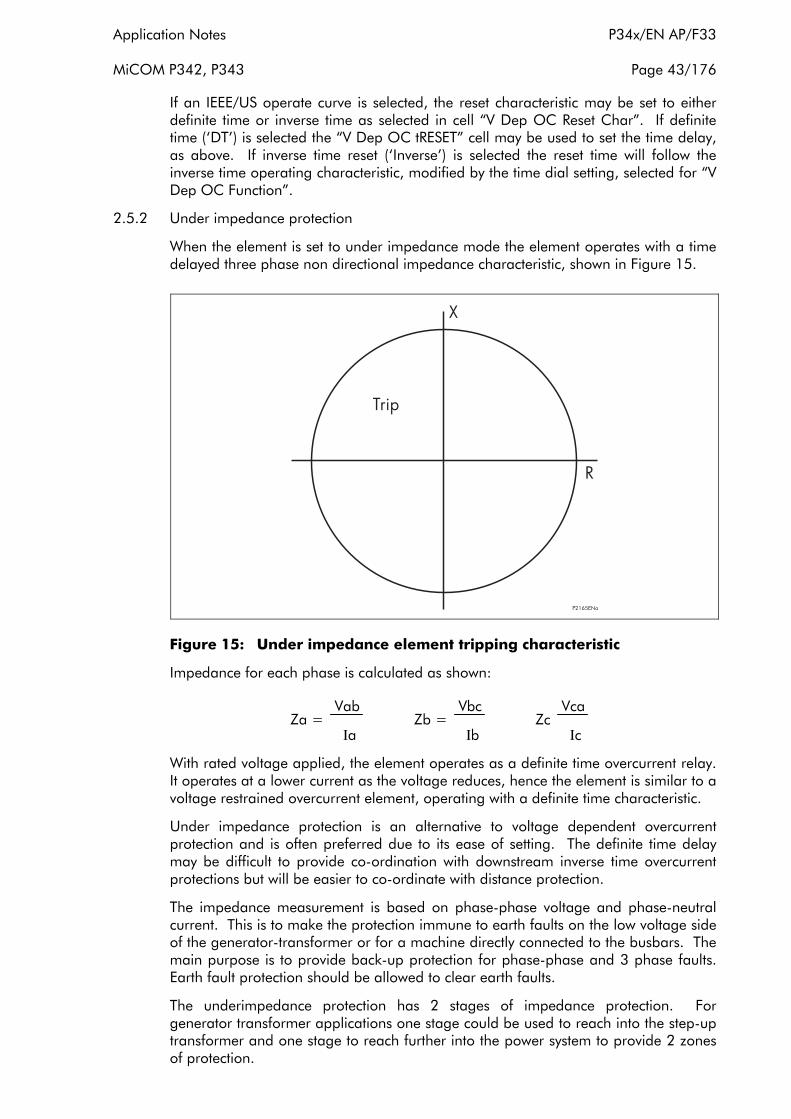
Application Notes P34x/EN AP/F33
MiCOM P342, P343 Page 43/176
If an IEEE/US operate curve is selected, the reset characteristic may be set to either definite time or inverse time as selected in cell “V Dep OC Reset Char”. If definite time (‘DT’) is selected the “V Dep OC tRESET” cell may be used to set the time delay, as above. If inverse time reset (‘Inverse’) is selected the reset time will follow the inverse time operating characteristic, modified by the time dial setting, selected for “V Dep OC Function”.
2.5.2 Under impedance protection
When the element is set to under impedance mode the element operates with a time delayed three phase non directional impedance characteristic, shown in Figure 15.
Figure 15: Under impedance element tripping characteristic
Impedance for each phase is calculated as shown:
Vab Vbc Vca Za = Zb = Zc
Ιa Ιb Ιc
With rated voltage applied, the element operates as a definite time overcurrent relay. It operates at a lower current as the voltage reduces, hence the element is similar to a voltage restrained overcurrent element, operating with a definite time characteristic.
Under impedance protection is an alternative to voltage dependent overcurrent protection and is often preferred due to its ease of setting. The definite time delay may be difficult to provide co-ordination with downstream inverse time overcurrent protections but will be easier to co-ordinate with distance protection.
The impedance measurement is based on phase-phase voltage and phase-neutral current. This is to make the protection immune to earth faults on the low voltage side of the generator-transformer or for a machine directly connected to the busbars. The main purpose is to provide back-up protection for phase-phase and 3 phase faults. Earth fault protection should be allowed to clear earth faults.
The underimpedance protection has 2 stages of impedance protection. For generator transformer applications one stage could be used to reach into the step-up transformer and one stage to reach further into the power system to provide 2 zones of protection.

P34x/EN AP/F33 Application Notes
Page 44/176 MiCOM P342, P343
The minimum phase current and the line voltage required for the P342/P343 under impedance protection to work is 20mA and 2V (Ιn = 1A, Vn = 100/120V) and 100mA and 8V (Ιn = 5A, Vn = 380/480V). Note, that the under impedance consists of separate three phase elements and the checking is done on a per phase basis, i.e. the inhibition of one phase will not affect the other phases.
2.5.2.1 Setting guidelines for under impedance function
Under impedance protection can be selected by setting “Backup Function” to ‘Under Impedance’. The protection is disabled if “Backup Function” is set to ‘Disabled’. As phase-phase voltage is used in the measurement of impedance the impedance settings should be increased by a factor of √3 to account for this.
The first stage impedance setting, “Z<1 Setting”, should be set to 70% of the maximum load impedance. This gives an adequate margin for short time overloads, voltage variation etc., whilst giving adequate back-up protection for generator, generator-transformer and busbar faults.
For example Z<1 = 3 x 0.7 x Vph - n
Ιflc x 1.2
allowing for a 20% overload of the generator full load current.
The second stage impedance setting “Z<2 Setting”, could be set to 50 – 60% of the generator-transformer impedance. This stage can then be used to obtain faster operation for faults closer to the generator.
The time delay, “Z<1 Time Delay” should allow co-ordination with downstream overcurrent and distance protection devices and with the zone 2 underimpedance protection. The time delay, “Z<2 Time Delay” should allow co-ordination with generator and transfomer LV phase fault protection.
The under impedance protection is provided with a timer hold facility, as described in section 2.5.1.1. Setting the hold timer, “Z< tRESET”, to a value other than zero, delays the resetting of the protection element timer for this period.
2.6 Undervoltage protection function (27)
Under voltage protection is not a commonly specified requirement for generator protection schemes. However, under voltage elements are sometimes used as interlocking elements for other types of protection, such as field failure. In the P340, this type of interlocking can be arranged via the relay scheme logic. Undervoltage protection may also be used for back-up protection where it may be difficult to provide adequate sensitivity with voltage dependant/underimpedance/negative phase sequence elements.
For an isolated generator, or isolated set of generators, a prolonged undervoltage condition could arise for a number of reasons. One reason would be failure of automatic voltage regulation (AVR) equipment. Where an auxiliary transformer is used to supply generator ancillary equipment, such as boiler-feed pumps, air-blowers, lubrication pumps etc., a prolonged undervoltage condition could adversely affect the performance of the machine. If such a situation is envisaged, the application of time-delayed undervoltage protection might be a consideration.

Application Notes P34x/EN AP/F33
MiCOM P342, P343 Page 45/176
A two stage undervoltage element is provided. The element can be set to operate from phase-phase or phase-neutral voltages. Each stage has an independent time delay which can be set to zero for instantaneous operation. Selectable, fixed Logic is included within the relay to allow the operation of the element to be inhibited during periods when the machine is isolated from the external system.
Each stage of undervoltage protection can be blocked by energising the relevant DDB signal via the PSL, (DDB 158, DDB 159). DDB signals are also available to indicate a 3 phase and per phase start and trip, (Starts: DDB 579-586, Trips: DDB 453-460).
Note: If the undervoltage protection is set for phase-phase operation then the DDB signals V<1/2 Start/Trip A/AB, V<1/2 Start/Trip B/BC, V<1/2 Start/ Trip C/CA refer to V<1/2 Start/Trip AB and V<1/2 Start/Trip BC and V<1/2 Start/Trip CA. If set for phase-neutral then the DDB signals V<1/2 Start/Trip A/AB, V<1/2 Start/Trip B/BC, V<1/2 Start/Trip C/CA refer to V<1/2 Start/Trip A and V<1/2 Start/Trip B and V<1/2 Start/Trip C.
The state of the DDB signals can be programmed to be viewed in the “Monitor Bit x” cells of the “COMMISSION TESTS” column in the relay.
Setting ranges for this element are shown in the following table:
Menu Text Default Setting Setting Range
Step Size Min Max
GROUP 1:
VOLTAGE PROTECTION
Undervoltage Sub Heading
V< Measur’t Mode Phase-Neutral Phase-Phase, Phase-Neutral
V< Operate Mode Any-phase Any Phase, Three phase
V<1 Function DT Disabled, DT, IDMT
V<1 Voltage Set
80V (Vn=100/120V)
320V (Vn=380/480V)
10V (Vn=100/120V)
40V (Vn=380/480V)
120V (Vn=100/120V)
480V (Vn=380/480V)
1V (Vn=100/120V)
4V (Vn=380/480V)
V<1 Time Delay 1 s 0 s 100 s 0.01 s
V<1 TMS 1 0.5 100 0.5
V<1 Poledead Inh Enabled Disabled Enabled
V<2 Function DT Disabled DT
V<2 Voltage Set
80V (Vn=100/120V)
320V (Vn=380/480V)
10V (Vn=100/120V)
40V (Vn=380/480V)
120V (Vn=100/120V)
480V (Vn=380/480V)
1V (Vn=100/120V)
4V (Vn=380/480V)
V<2 Time Delay 1 s 0 s 100 s 0.01 s
V<1 Poledead Inh Enabled Disabled, Enabled
The IDMT characteristic available on the first stage is defined by the following formula:
t = K / (1 – M)

P34x/EN AP/F33 Application Notes
Page 46/176 MiCOM P342, P343
where
K = Time Multiplier Setting (V<1 TMS)
t = Operating Time in Seconds
M = Measured Voltage /Relay Setting Voltage (V<1 Voltage Set)
2.6.1 Setting guidelines for undervoltage protection
Stage 1 may be selected as either ‘IDMT’ (for inverse time delayed operation), ‘DT’ (for definite time delayed operation) or ‘Disabled’, within the “V<1 Function” cell. Stage 2 is definite time only and is Enabled/Disabled in the “V<2 Status” cell. The time delay (“V<1 TMS” - for IDMT curve; “V<1 Time Delay”, “V<2 Time Delay” - for definite time) should be adjusted accordingly.
The undervoltage protection can be set to operate from phase-phase or phase-neutral voltage as selected by “V< Measur’t Mode”. Single or three phase operation can be selected in “V<1 Operate Mode”. When ‘Any Phase’ is selected, the element will operate if any phase voltage falls below setting, when ‘Three Phase’ is selected the element will operate when all three phase voltages are below the setting.
If the undervoltage protection function is to be used for back-up protection, the voltage setting, ”V<1 Voltage Set”, should be set above the steady-state phase-phase voltage seen by the relay for a three-phase fault at the remote end of any feeder connected to the generator bus. Allowances should be made for the fault current contribution of parallel generators, which will tend to keep the generator voltage up. If the element is set to operate from phase to phase voltages operation for earth faults can be minimised, i.e. set “V< Measur’t Mode” to ‘Phase-Phase’. To allow detection of any phase to phase fault, “V< Operate Mode” should be set to ‘Any-Phase’. Equations for determining the phase-phase voltage seen by the relay under such circumstances are given in section 2.5.1.2.
The operating characteristic would normally be set to definite time, set “V<1 Function” to ‘DT’. The time delay, “V<1 Time Delay”, should be set to coordinate with downstream protections and the System Back-up protection of the relay, if enabled. Additionally, the delay should be long enough to prevent unwanted
operation of the under voltage protection for transient voltage dips. These may occur during clearance of faults further into the power system or by starting of local machines. The required time delay would typically be in excess of 3s-5s.
The second stage can be used as an alarm stage to warn the user of unusual voltage conditions so that corrections can be made. This could be useful if the machine is being operated with the AVR selected to manual control.
Where the relay is used to provide the protection required for connecting the generator in parallel with the local electricity supply system (e.g. requirements of G59 in the UK), the local electricity supply authority may advise settings for the element. The settings must prevent the generator from exporting power to the system with voltage outside of the statutory limits imposed on the supply authority.
To prevent operation of any under voltage stage during normal shutdown of the generator “poledead” logic is included in the relay. This is facilitated by selecting “V Poledead Inh” to ‘Enabled’. This will ensure that when a poledead condition is detected (i.e. all phase currents below the undercurrent threshold or CB Open, as determined by an opto isolator and the PSL) the undervoltage element will be inhibited.
Application Notes P34x/EN AP/F33
MiCOM P342, P343 Page 47/176
2.7 Overvoltage protection
A generator terminal overvoltage condition could arise when the generator is running but not connected to a power system, or where a generator is providing power to an islanded power system. Such an over voltage could arise in the event of a fault with automatic voltage regulating equipment or if the voltage regulator is set for manual control and an operator error is made. Overvoltage protection should be set to prevent possible damage to generator insulation, prolonged overfluxing of the generating plant, or damage to power system loads.
When a generator is synchronised to a power system with other sources, an overvoltage could arise if the generator is lightly loaded supplying a high level of power system capacitive charging current. An overvoltage condition might also be possible following a system separation, where a generator might experience full-load rejection whilst still being connected to part of the original power system. The automatic voltage regulating equipment and machine governor should quickly respond to correct the overvoltage condition in these cases. However, over voltage protection is advisable to cater for a possible failure of the voltage regulator or for the regulator having been set to manual control. In the case of Hydro generators, the response time of the speed governing equipment can be so slow that transient over speeding up to 200% of nominal speed could occur. Even with voltage regulator action, such over speeding can result in a transient over voltage as high as 150%. Such a high voltage could result in rapid insulation damage.
A two stage overvoltage element is provided. The element can be set to operate from phase-phase or phase-neutral voltages. Each stage has an independent time delay which can be set to zero for instantaneous operation.
Each stage of overvoltage protection can be blocked by energising the relevant DDB signal via the PSL, (DDB 368, DDB 369). DDB signals are also available to indicate a 3 phase and per phase start and trip, (Starts: DDB 587-594, Trips: DDB 461-468).
Note: If the overvoltage protection is set for phase-phase operation then the DDB signals V>1/2 Start/Trip A/AB, V>1/2 Start/Trip B/BC, V>1/2 Start/Trip C/CA refer to V>1/2 Start/Trip AB and V>1/2 Start/Trip BC and V>1/2 Start/Trip CA. If set for phase-neutral then the DDB signals V>1/2 Start/Trip A/AB, V>1/2 Start/Trip B/BC, V>1/2 Start/Trip C/CA refer to V>1/2 Start/Trip A and V>1/2 Start/Trip B and V>1/2 Start/Trip C.
Setting ranges for this element are shown in the following table:
Menu Text Default Setting Setting Range
Step Size Min Max
GROUP 1: VOLTAGE PROTECTION
Overvoltage Sub Heading
V> Measur’t Mode Phase-Neutral Phase-Phase, Phase-Neutral
V> Operate Mode Any-phase Any Phase, Three phase
V>1 Function DT Disabled, DT, IDMT
V>1 Voltage Set
150V (Vn=100/120V)
600V (Vn=380/480V)
60V (Vn=100/120V)
240V (Vn=380/480V)
185V (Vn=100/120V)
740V (Vn=380/480V)
1V (Vn=100/120V)
4V (Vn=380/480V)
V>1 Time Delay 1 s 0 s 100 s 0.01 s
P34x/EN AP/F33 Application Notes
Page 48/176 MiCOM P342, P343
Menu Text Default Setting Setting Range
Step Size Min Max
GROUP 1: VOLTAGE PROTECTION
V>1 TMS 1 0.5 100 0.5
V>2 Status DT Disabled DT
V>2 Voltage Set
130V (Vn=100/120V)
520V (Vn=380/480V)
60V (Vn=100/120V)
240V (Vn=380/480V)
185V (Vn=100/120V)
740V (Vn=380/480V)
1V (Vn=100/120V)
4V (Vn=380/480V)
V>2 Time Delay 1 s 0 s 100 s 0.01 s
The IDMT characteristic available on the first stage is defined by the following formula:
t = K / (M - 1)
where
K = Time Multiplier Setting (“V>1 TMS”)
t = Operating Time in Seconds
M = Measured Voltage/Relay Setting Voltage (“V>1 Voltage Set”)
2.7.1 Setting guidelines for overvoltage protection
Stage 1 may be selected as either ‘IDMT’ (for inverse time delayed operation), ‘DT’ (for definite time delayed operation) or ‘Disabled’, within the “V>1 Function” cell. Stage 2 has a definite time delayed characteristic and is Enabled/Disabled in the “V>2 Status” cell. The time delay (“V>1 TMS” - for IDMT curve; “V>1 Time Delay”, “V>2 Time Delay” - for definite time) should be selected accordingly.
The undervoltage protection can be set to operate from Phase-Phase or Phase-Neutral voltage as selected by “V> Measur’t Mode” cell. Single or three phase operation can be selected in “V> Operate Mode” cell. When ‘Any Phase’ is selected the element will operate if any phase voltage falls below setting, when ‘Three Phase’ is selected the element will operate when all three phase voltages are above the setting.
Generators can typically withstand a 5% overvoltage condition continuously. The withstand times for higher overvoltages should be declared by the generator manufacturer.
To prevent operation during earth faults, the element should operate from the phase-phase voltages, to achieve this “V>1 Measur’t Mode” can be set to ‘Phase-Phase’ with “V>1 Operating Mode” set to ‘Three-Phase’. The overvoltage threshold, “V>1 Voltage Set”, should typically be set to 100%-120% of the nominal phase-phase voltage seen by the relay. The time delay, “V>1 Time Delay”, should be set to prevent unwanted tripping of the delayed overvoltage protection function due to transient over voltages that do not pose a risk to the generating plant; e.g. following load rejection where correct AVR/Governor control occurs. The typical delay to be applied would be 1s-3s, with a longer delay being applied for lower voltage threshold settings.
Application Notes P34x/EN AP/F33
MiCOM P342, P343 Page 49/176
The second stage can be used to provide instantaneous high-set over voltage protection. The typical threshold setting to be applied, “V>2 Voltage Set”, would be 130-150% of the nominal phase-phase voltage seen by the relay, depending on plant manufacturers’ advice. For instantaneous operation, the time delay, “V>2 Time Delay”, should be set to 0s.
Where the relay is used to provide the protection required for connecting the generator in parallel with the local electricity supply system (e.g. requirements of G59 in the UK), the local electricity supply authority may advise settings for the element. The settings must prevent the generator from exporting power to the system with voltages outside of the statutory limits imposed on the supply authority.
If phase to neutral operation is selected, care must be taken to ensure that the element will grade with downstream protections during earth faults, where the phase-neutral voltage can rise significantly.
2.8 Underfrequency protection
Underfrequency operation of a generator will occur when the power system load exceeds the prime mover capability of an islanded generator or group of generators. Power system overloading can arise when a power system becomes split, with load left connected to a set of ‘islanded’ generators that is in excess of their capacity. Such events could be compensated for by automatic load shedding. In this case, underfrequency operation would be a transient condition. In the event of the load shedding being unsuccessful, the generators should be provided with back-up underfrequency protection.
An underfrequency condition, at nominal voltage, may result in some over fluxing of a generator and its associated electrical plant. However, the more critical considerations would be in relation to blade stresses being incurred with high-speed turbine generators; especially steam-driven sets. When not running at nominal frequency, abnormal blade resonance’s can be set up which, if prolonged, could lead to turbine disc component fractures. Such effects can be accumulative and so operation at frequencies away from nominal should be limited as much as possible, to avoid the need for early plant inspections/overhaul. Underfrequency running is difficult to contend with, since there is little action that can be taken at the generating station in the event of overloading, other than to shut the generator down.
Four independent definite time-delayed stages of underfrequency protection are offered. Two additional overfrequency stages can also be reconfigured as underfrequency protection by reprogramming the Programmable Scheme Logic. As well as being able to initiate generator tripping, the underfrequency protection can
also be arranged to initiate local load-shedding, where appropriate. Selectable fixed scheme logic is provided to allow each stage of underfrequency protection to be disabled when the outgoing CB is open, to prevent unnecessary load tripping.
Each stage of underfrequency protection can also be blocked by energising the relevant DDB signal via the PSL, (DDB 374 - DDB 377). DDB signals are also available to indicate start and trip of each stage, (Starts: DDB 622-625, Trips: DDB 469-472). The state of the DDB signals can be programmed to be viewed in the “Monitor Bit x” cells of the “COMMISSION TESTS” column in the relay.
Setting ranges for this element are shown in the following table:

P34x/EN AP/F33 Application Notes
Page 50/176 MiCOM P342, P343
Menu Text Default Setting Setting Range
Step Size Min Max
GROUP 1: FREQUENCY PROTECTION
Under frequency Sub Heading
F<1 Status Enabled Disabled, Enabled
F<1 Setting 49.5 Hz 45 Hz 65 Hz 0.01 Hz
F<1 Time Delay 4 s 0.1 s 100 s 0.1 s
F<2 Status Enabled Disabled, Enabled
F<2 Setting 49.5 Hz 45 Hz 65 Hz 0.01 Hz
F<2 Time Delay 4 s 0.1 s 100 s 0.1 s
F<3 Status Enabled Disabled Enabled
F<3 Setting 49.5 Hz 45 Hz 65 Hz 0.01 Hz
F<3 Time Delay 4 s 0.1 s 100 s 0.1 s
F<4 Status Enabled Disabled Enabled
F<4 Setting 49.5 Hz 45 Hz 65 Hz 0.01 Hz
F<4 Time Delay 4 s 0.1 s 100 s 0.1 s
F< Function Link 1111
Bit 0 - Enable Block F<1 during Poledead Bit 1 - Enable Block F<2 during Poledead Bit 2 - Enable Block F<3 during Poledead Bit 3 - Enable Block F<4 during Poledead
2.8.1 Setting guidelines for underfrequency protection
Each stage of under frequency protection may be selected as ‘Enabled’ or ‘Disabled’, within the “F<x Status” cells. The frequency pickup setting, “F<x Setting”, and time delays, “F<x Time Delay”, for each stage should be selected accordingly.
The protection function should be set so that declared frequency-time limits for the generating set are not infringed. Typically, a 10% under frequency condition should be continuously sustainable.
For industrial generation schemes, where generation and loads may be under common control/ownership, the P340 under frequency protection function could be used to initiate local system load-shedding. Four stage under frequency/load shedding can be provided. The final stage of underfrequency protection should be used to trip the generator.
Where separate load shedding equipment is provided, the underfrequency protection should co-ordinate with it. This will ensure that generator tripping will not occur in the event of successful load shedding following a system overload. Two stages of under frequency protection could be set-up, as illustrated in Figure 16, to co-ordinate with multi-stage system load-shedding.

Application Notes P34x/EN AP/F33
MiCOM P342, P343 Page 51/176
Figure 16: Co-ordination of underfrequency protection function with system load shedding
To prevent operation of any underfrequency stage during normal shutdown of the generator “poledead” logic is included in the relay. This is facilitated for each stage by setting the relevant bit in “F< Function Link”. For example if “F< Function Link” is set to 0111, Stage 1, 2 and 3 of underfrequency protection will be blocked when the generator CB is open. Selective blocking of the frequency protection stages in this way will allow a single stage of protection to be enabled during synchronisation or offline running to prevent unsynchronised overfluxing of the machine. When the machine is synchronised, and the CB closed, all stages of frequency protection will be enabled providing a multi stage load shed scheme if desired.
Where the relay is used to provide the protection required for connecting the generator in parallel with the local electricity supply system (e.g. requirements of G59 in the UK), the local electricity supply authority may advise settings for the element. The settings must prevent the generator from exporting power to the system with frequency outside of the statutory limits imposed on the supply authority. Where the local external load exceeds the generator capacity, underfrequency protection may be used to provide ‘Loss of Mains’ protection.

P34x/EN AP/F33 Application Notes
Page 52/176 MiCOM P342, P343
2.9 Overfrequency protection function
Overfrequency running of a generator arises when the mechanical power input to the alternator is in excess of the electrical load and mechanical losses. The most common occurrence of overfrequency is after substantial loss of load. When a rise in running speed occurs, the governor should quickly respond to reduce the mechanical input power, so that normal running speed is quickly regained. Overfrequency protection may be required as a back-up protection function to cater for governor or throttle control failure following loss of load or during unsynchronised running.
Moderate overfrequency operation of a generator is not as potentially threatening to the generator and other electrical plant as underfrequency running. Action can be taken at the generating plant to correct the situation without necessarily shutting down the generator.
Severe overfrequency operation of a high-speed generating set could result in plant damage, as described in section 2.12, as a result of the high centrifugal forces that would be imposed on rotating components.
Two independent time-delayed stages of overfrequency protection are provided.
Each stage of protection can be blocked by energising the relevant DDB signal via the PSL, (DDB 378, DDB 379). DDB signals are also available to indicate start and trip of each stage, (Starts: DDB 626-627, Trips: DDB 473-474). A further DDB ‘Field Fail Alarm’ signal is generated from the field failure alarm stage (DDB 309). The state of the DDB signals can be programmed to be viewed in the “Monitor Bit x” cells of the “COMMISSION TESTS” column in the relay.
Setting ranges for this element are shown in the following table:
Menu Text Default Setting Setting Range
Step Size Min Max
GROUP 1: FREQUENCY PROTECTION
Overfrequency Sub Heading
F>1 Status Enabled Disabled, Enabled
F>1 Setting 49.5 Hz 45 Hz 68 Hz 0.01 Hz
F>1 Time Delay 4 s 0.1 s 100 s 0.1 s
F>2 Status Enabled Disabled, Enabled
F>2 Setting 49.5 Hz 45 Hz 68 Hz 0.01 Hz
F>2 Time Delay 4 s 0.1 s 100 s 0.1 s
2.9.1 Setting guidelines for overfrequency protection
Each stage of overfrequency protection may be selected as Enabled or Disabled, within the “F>x Status” cells. The frequency pickup setting, “F>x Setting”, and time delays, “F>x Time Delay”, for each stage should be selected accordingly.
The P340 overfrequency settings should be selected to co-ordinate with normal, transient overfrequency excursions following full-load rejection. The generator manufacturer should declare the expected transient overfrequency behaviour, which should comply with international governor response standards. A typical overfrequency setting would be 10% above nominal.

Application Notes P34x/EN AP/F33
MiCOM P342, P343 Page 53/176
Where the relay is used to provide the protection required for connecting the generator in parallel with the local electricity supply system (e.g. requirements of G59 in the UK), the local electricity supply authority may advise settings for the element. The settings must prevent the generator from exporting power to the system with frequency outside of the statutory limits imposed on the supply authority.
2.10 Field failure protection function (40)
Complete loss of excitation may arise as a result of accidental tripping of the excitation system, an open circuit or short circuit occurring in the excitation DC circuit, flashover of any slip rings or failure of the excitation power source. The field failure protection of the P340 consists of two elements, an impedance element with two time delayed stages and a power factor alarm element, illustrated below in Figure 17. The elements operate from A phase current and A phase voltage signals measured by the ΙA and VA inputs on the relay. The minimum phase current and voltage required for P342/P343 field failure protection to work is 20mA and 1V (Ιn = 1A, Vn = 100/120V) and 100mA and 4V (Ιn = 5A, Vn = 380/480V).
Figure 17: Field failure protection characteristics
When the excitation of a synchronous generator fails, its internal e.m.f. will decay. This results in the active power output of the machine falling and in an increasing level of reactive power being drawn from the power system. As the active power output falls, the mechanical drive can accelerate the machine so that it will gently pole slip and run at a super synchronous speed. This results in slip frequency currents being induced in the rotor body, damper windings and in the field windings. The slip-induced, low-frequency rotor currents will result in a rotor flux being produced. The machine would then be excited from the power system and hence be operating as an induction generator. The ability to reach such a stabilised state will be dependent on the machine’s effective speed-torque characteristic when operating as an induction generator, and also on the power system being able to supply the required reactive power without severe voltage depression.
Stable operation as an induction generator might be achieved at low slip (0.1-0.2% above synchronous speed), particularly in the case of salient pole machines. The machine may be able to maintain an active power output (perhaps 20-30% of rating) whilst drawing reactive power from the power system (generating at a highly leading power factor). This condition could probably be sustained for many minutes without rotor damage being incurred and may not be detectable by traditional field failure impedance characteristic elements. The P340, however, offers a power factor alarm
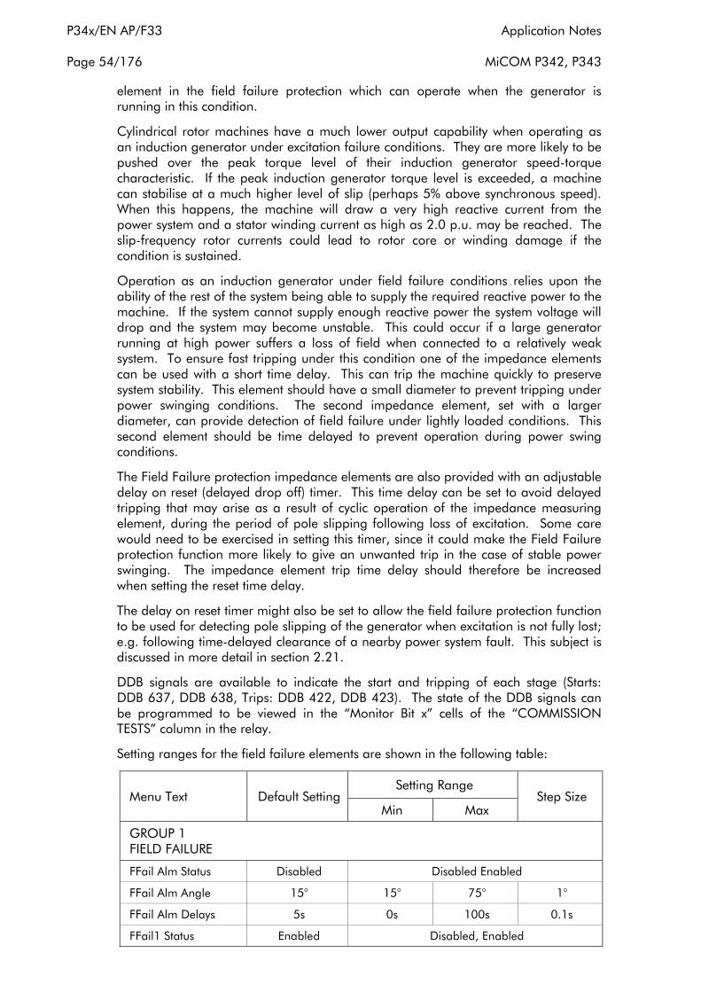
P34x/EN AP/F33 Application Notes
Page 54/176 MiCOM P342, P343
element in the field failure protection which can operate when the generator is running in this condition.
Cylindrical rotor machines have a much lower output capability when operating as an induction generator under excitation failure conditions. They are more likely to be pushed over the peak torque level of their induction generator speed-torque characteristic. If the peak induction generator torque level is exceeded, a machine can stabilise at a much higher level of slip (perhaps 5% above synchronous speed). When this happens, the machine will draw a very high reactive current from the power system and a stator winding current as high as 2.0 p.u. may be reached. The slip-frequency rotor currents could lead to rotor core or winding damage if the condition is sustained.
Operation as an induction generator under field failure conditions relies upon the ability of the rest of the system being able to supply the required reactive power to the machine. If the system cannot supply enough reactive power the system voltage will drop and the system may become unstable. This could occur if a large generator running at high power suffers a loss of field when connected to a relatively weak system. To ensure fast tripping under this condition one of the impedance elements can be used with a short time delay. This can trip the machine quickly to preserve system stability. This element should have a small diameter to prevent tripping under power swinging conditions. The second impedance element, set with a larger diameter, can provide detection of field failure under lightly loaded conditions. This second element should be time delayed to prevent operation during power swing conditions.
The Field Failure protection impedance elements are also provided with an adjustable delay on reset (delayed drop off) timer. This time delay can be set to avoid delayed tripping that may arise as a result of cyclic operation of the impedance measuring element, during the period of pole slipping following loss of excitation. Some care would need to be exercised in setting this timer, since it could make the Field Failure protection function more likely to give an unwanted trip in the case of stable power swinging. The impedance element trip time delay should therefore be increased when setting the reset time delay.
The delay on reset timer might also be set to allow the field failure protection function to be used for detecting pole slipping of the generator when excitation is not fully lost; e.g. following time-delayed clearance of a nearby power system fault. This subject is discussed in more detail in section 2.21.
DDB signals are available to indicate the start and tripping of each stage (Starts: DDB 637, DDB 638, Trips: DDB 422, DDB 423). The state of the DDB signals can be programmed to be viewed in the “Monitor Bit x” cells of the “COMMISSION TESTS” column in the relay.
Setting ranges for the field failure elements are shown in the following table:
Menu Text Default Setting Setting Range
Step Size Min Max
GROUP 1 FIELD FAILURE
FFail Alm Status Disabled Disabled Enabled
FFail Alm Angle 15° 15° 75° 1°
FFail Alm Delays 5s 0s 100s 0.1s
FFail1 Status Enabled Disabled, Enabled

Application Notes P34x/EN AP/F33
MiCOM P342, P343 Page 55/176
Menu Text Default Setting Setting Range
Step Size Min Max
GROUP 1 FIELD FAILURE
FFail1 –Xa1
20/Ιn Ω (Vn=100/120V)
80/Ιn Ω (Vn=380/480V)
0/Ιn Ω (Vn=100/120V)
0/Ιn Ω (Vn=380/480V)
40/Ιn Ω (Vn=100/120V)
160/Ιn Ω (Vn=380/480V)
0.5/Ιn Ω (Vn=100/120V)
2/Ιn Ω (Vn=380/480V)
FFail1 Xb1
220/Ιn Ω (Vn=100/120V)
880/Ιn Ω (Vn=380/480V)
25/Ιn Ω (Vn=100/120V)
100/Ιn Ω (Vn=380/480V)
325/Ιn Ω (Vn=100/120V)
1300/Ιn Ω (Vn=380/480V)
1/Ιn Ω (Vn=100/120V)
4/Ιn Ω (Vn=380/480V)
FFail1 TimeDelay 5 s 0 s 100 s 0.1 s
FFail1 DO Timer 0 s 0 s 10 s 0.1 s
FFail2 Status Enabled Disabled, Enabled
FFail2 –Xa2
20/Ιn Ω (Vn=100/120V)
80/Ιn Ω (Vn=380/480V)
0/Ιn Ω (Vn=100/120V)
0/Ιn Ω (Vn=380/480V)
40/Ιn Ω (Vn=100/120V)
160/Ιn Ω (Vn=380/480V)
0.5/Ιn Ω (Vn=100/120V)
2/Ιn Ω (Vn=380/480V)
FFail2 Xb2
220/Ιn Ω (Vn=100/120V)
880/Ιn Ω (Vn=380/480V)
25/Ιn Ω (Vn=100/120V)
100/Ιn Ω (Vn=380/480V)
325/Ιn Ω (Vn=100/120V)
1300/Ιn Ω (Vn=380/480V)
1/Ιn Ω (Vn=100/120V)
4/Ιn Ω (Vn=380/480V)
FFail2 TimeDelay 5 s 0 s 100 s 0.1 s
FFail2 DO Timer 0 s 0 s 10 s 0.1 s
2.10.1 Setting guidelines for field failure protection
Each stage of field failure protection may be selected as ‘Enabled’ or ‘Disabled’, within the “FFail1 Status”, “FFail2 Status” cells. The power factor alarm element may be selected as Enabled or Disabled within the “FFail Alm Status” cell.
2.10.1.1Impedance element 1
To quickly detect a loss-of field condition, the diameter of the field failure impedance characteristic (“FFail1 Xb1”) should be set as large as possible, without conflicting with the impedance that might be seen under normal stable conditions or during stable power swing conditions.
Where a generator is operated with a rotor angle of less than 90° and never at a leading power factor, it is recommended that the diameter of the impedance characteristic, “FFail1 Xb1”, is set equal to the generator direct-axis synchronous reactance. The characteristic offset, “FFail1 -Xa1” should be set equal to half the direct-axis transient reactance (0.5Xd’) in secondary ohms.
“FFail1 Xb1” = Xd
“FFail1 -Xa1” = 0.5 Xd’
where
Xd = Generator direct-axis synchronous reactance in ohms
Xd’ = Generator direct-axis transient reactance in ohms

P34x/EN AP/F33 Application Notes
Page 56/176 MiCOM P342, P343
Where high-speed voltage regulation equipment is used it may be possible to operate generators at rotor angles up to 120°. In this case, the impedance characteristic diameter, “FFail1 Xb1”, should be set to 50% of the direct-axis synchronous reactance (0.5Xd) and the offset, “FFail1 -Xa1”, should be set to 75% of the direct axis transient reactance (0.75Xd’).
“FFail1 Xb1” = 0.5 Xd
“FFail1 -Xa1” = 0.75 Xd’
The field failure protection time delay, “FFail1 Time Delay”, should be set to minimise the risk of operation of the protection function during stable power swings following system disturbances or synchronisation. However, it should be ensured that the time delay is not so long that stator winding or rotor thermal damage will occur. A typical stator winding should be able to withstand a current of 2.0 p.u. for the order of 15s. It may also take some time for the impedance seen at the generator terminals to enter the characteristic of the protection. A time delay less than 10s would typically be applied. The minimum permissible delay, to avoid problems of false tripping due to stable power swings with the above impedance settings, would be of the order of 0.5s.
The protection reset (delayed drop off) timer, “FFail1 DO Timer”, would typically be set to 0s to give instantaneous reset of the stage. A setting other than 0s can be used to provide an integrating function for instances when the impedance may cyclically enter and exit the characteristic. This can allow detection of pole slipping conditions, for more information see section 2.21. When settings other than 0s are used the protection pick-up time delay, “FFail1 Time Delay”, should be increased to prevent mal-operation during stable power swing conditions.
2.10.1.2Impedance element 2
The second impedance element can be set to give fast operation when the field fails under high load conditions. The diameter of the characteristic, “FFail2 Xb2”, should be set to 1 p.u. The characteristic offset, “FFail2 -Xa2”, should be set equal to half the direct-axis transient reactance (0.5Xd’).
kV2
FFail2 Xb2 = MVA
FFail2 -Xa2 = 0.5 Xd’
This setting will detect a field failure condition from full load to about 30% load.
The time delay, “FFail2 Time Delay”, can be set to instantaneous, i.e. 0s.
The protection reset (delayed drop off) timer, “FFail2 DO Timer”, would typically be set to 0s to give instantaneous reset of the stage. A setting other than 0s can be used to provide an integrating function for instances when the impedance may cyclically enter and exit the characteristic. This can allow detection of pole slipping conditions, for more information see section 2.21. When settings other than 0s are used the protection pick-up time delay, “FFail2 Time Delay”, should be increased to prevent maloperation during stable power swing conditions.
2.10.1.3Power factor element
Salient pole machines can run continuously as induction generators generating significant power and operation under these conditions may not be detectable by an impedance characteristic. The power factor alarm can be used to signal to the operator that excitation has failed under these conditions.

Application Notes P34x/EN AP/F33
MiCOM P342, P343 Page 57/176
The angle setting, “FFail Alm Angle”, should be set to greater than any angle that the machine could be operated at in normal running. A typical setting would be 15°, equivalent to a power factor of 0.96 leading. The power factor element time delay, “FFail Alm Delay”, should be set longer than the impedance element time delay setting (“FFail1 Time Delay”). This is to prevent operation of the alarm element under transient conditions such as power swinging and to provide discrimination where a field failure condition may not be detected by conventional field failure impedance elements.
2.11 Negative phase sequence thermal protection
The Negative Phase Sequence (NPS) protection provided by the P340 is a true thermal replica with a definite-time alarm stage. The relay derives the negative phase sequence operating quantity from the following equation:
Ιa + a2 Ιb + aΙcΙ2 = where a = 1.0 ∠120°
3
Unbalanced loading results in the flow of positive and negative sequence current components. Load unbalance can arise as a result of single phase loading, nonlinear loads (involving power electronics or arc furnaces, etc.), uncleared or repetitive asymmetric faults, fuse operation, single-pole tripping and reclosing on transmission systems, broken overhead line conductors and asymmetric failures of switching devices. Any negative phase sequence component of stator current will set up a reverse-rotating component of stator flux that passes the rotor at twice synchronous speed. Such a flux component will induce double frequency eddy currents in the rotor, which can cause overheating of the rotor body, main rotor windings, damper windings etc.
Where a machine has a high continuous negative phase sequence current withstand level (Ι2 amp), as in the case of typical salient-pole machines, it would not be essential to enable the NPS protection function. The NPS protection function can, however, offer a better method of responding to an uncleared asymmetric fault remote from the generator bus. As mentioned in section 2.5.1.2, it may be difficult to set the voltage dependant overcurrent protection function to detect a remote fault and co-ordinate with feeder backup protection for a close-up 3-phase fault.
For high levels of negative phase sequence current, eddy current heating can be considerably in excess of the heat dissipation rate. Thus, virtually all the heat acquired during the period of unbalance will be retained within the rotor. With this assumption, the temperature attained within any critical rotor component will be dependent on the duration of the unbalance (t seconds) and the level of NPS current (I2 per unit) and is proportional to I22t. Synchronous generators are assigned a per-unit I22t thermal capacity constant (Kg) to define their short time NPS current withstand ability, see column 3 in Table 1. Various rotor components have different short time thermal capacities and the most critical (lowest value of I22t) should form the basis of the generator manufacturer’s short time I22t withstand claim.
Many traditional forms of generator NPS thermal protection relays have been designed with an extremely inverse (Ι22t) operating time characteristic. Where the operating time of the characteristic is dependent solely on the instantaneous magnitude of negative phase sequence current present. This characteristic would be set to match the claimed generator thermal capacity. This is satisfactory when considering the effects of high values of negative phase sequence current.
For intermediate levels of NPS current, the rate of heating is slower. As a result, heat dissipation should be considered.
P34x/EN AP/F33 Application Notes
Page 58/176 MiCOM P342, P343
The basic expression of t = K/Ι2cmr does not cater for the effects of heat dissipation or for low standing levels of negative phase sequence current. The latter resulting in an increase in rotor temperature which remains within the machines design limits. An existing, tolerable, level of negative phase sequence current (Ι2<Ι2cmr), has the effect of reducing the time to reach the critical temperature level, if the negative phase sequence current level should increase beyond Ι2cmr. The P340 NPS thermal replica is designed to overcome these problems by modelling the effects of low standing levels of negative phase sequence currents.
The temperature rise in critical rotor components is related to the negative phase sequence current (I2 per unit) and to time (t seconds) as follows. This assumes no preceding negative phase sequence current:
θ°C ∝ I22 (1 - e-t/τ)
where
τ = the thermal time constant, τ = Kg/I2CMR 2
Kg is the generator’s per-unit thermal capacity constant in seconds.
I2CMR is the generator’s per-unit continuous maximum I2 rating.
The limiting continuous maximum temperature (θCMR) would be reached according to the following current-time relationship:
θ°C = θCMR I22 (1 - e-t/τ) = I2CMR 2
From the above, the time for which a level of negative phase sequence current in excess of I2CMR can be maintained is expressed as follows:
t = - (Kg/I2CMR 2) loge (1- (I2CMR/I2))
The P340 negative phase sequence element offers a true thermal characteristic according to the following formula:
(Ι2>2 k Setting) t = - ( Ι2>2 Current set )2 Loge 1
(Ι2>2 Current set)
Ι2
2
Note: All current terms are in per-unit, based on the relay rated current, Ιn.
When the protected generator sees a reduction in negative phase sequence current, metallic rotor components will decrease in temperature. The relay is provided with a separate thermal capacity setting (Ι2>2 KRESET), used when there is a reduction in Ι2.
The negative sequence protection element will respond to system phase to earth and phase to phase faults. Therefore, the element must be set to grade with downstream earth and phase fault protections. To aid grading with downstream devices a definite minimum operating time for the operating characteristic can be set. The definite minimum time setting should be set to provide an adequate margin between the operation of the negative phase sequence thermal protection function and external protection. The co-ordination time margin used should be in accordance with the usual practice adopted by the customer for backup protection co-ordination.
For levels of negative phase sequence current that are only slightly in excess of the thermal element pick-up setting, there will be a noticeable deviation between the P340 negative phase sequence thermal protection current-time characteristic and that of the simple Ι22t characteristic. For this reason, a maximum negative phase

Application Notes P34x/EN AP/F33
MiCOM P342, P343 Page 59/176
sequence protection trip time setting is provided. This maximum time setting also limits the tripping time of the negative phase sequence protection for levels of unbalance where there may be uncertainty about the machine’s thermal withstand.
A time delayed negative sequence overcurrent alarm stage is provided to give the operator early warning of an unbalanced condition that may lead to generator tripping. This can allow corrective action to be taken to reduce the unbalance in the load.
The Negative Sequence element uses the current measured at the ΙA, ΙB, ΙC inputs on the relay.
Thermal state of the machine can be viewed in the “NPS Thermal” cell in the “MEASUREMENTS 3” column. The thermal state can be reset by selecting ‘Yes’ in the “Reset NPS Thermal” cell in “Measurements 3”. Alternatively the thermal state can be reset by energising DDB 389 “Reset Ι2 Thermal” via the relay PSL.
A DDB signal is also available to indicate tripping of the element (DDB 424). A further DDB ‘NPS Alarm’ signal is generated from the NPS thermal alarm stage (DDB 306). The state of the DDB signal can be programmed to be viewed in the “Monitor Bit x” cells of the “COMMISSION TESTS” column in the relay.
Figure 18: Negative phase sequence thermal characteristic

P34x/EN AP/F33 Application Notes
Page 60/176 MiCOM P342, P343
Setting ranges for the negative phase sequence thermal element are shown in the following table:
Menu Text Default Setting Setting Range
Step Size Min Max
GROUP 1: NPS THERMAL
Ι2>1 Alarm Enabled Disabled, Enabled
Ι2>1 Current Set 0.05 Ιn A 0.03 Ιn A 0.5 Ιn A 0.01 Ιn A
Ι2>1 Time Delay 20 s 2 s 60 s 0.1 s
Ι2>2 Trip Enabled Disabled, Enabled
Ι2>2 Current set 0.1 Ιn A 0.05 Ιn A 0.5 Ιn A 0.01 Ιn A
Ι2>2 k Setting 15 2 40 0.1
Ι2>2 kRESET 15 2 40 0.1
Ι2>2 tMAX 1000 s 500 s 2000 s 10 s
Ι2>2 tMIN 0.25 s 0.25 s 40 s 0.25 s
2.11.1 Setting guidelines for negative phase sequence thermal protection
The alarm and trip stages of the negative phase sequence thermal protection may be selected as ‘Enabled’ or ‘Disabled’, within the “Ι2>1 Alarm” and “Ι2>2 Trip” cells respectively.
Synchronous machines will be able to withstand a certain level of negative phase sequence stator current continuously. All synchronous machines will be assigned a continuous maximum negative phase sequence current (Ι2cmr per-unit) rating by the manufacturer. For various categories of generator, minimum negative phase
sequence current withstand levels have been specified by international standards, such as IEC60034-1 and ANSI C50.13-1977 [1]. The IEC60034-1 figures are given in Table 1.
Generator type Maximum Ι2/Ιn for
continuous operation
Maximum (Ι2/Ιn)2t for operation under fault
conditions, Kg
Salient-pole:
Indirectly cooled 0.08 20
Directly cooled (inner cooled) stator and/or field
0.05 15
Cylindrical rotor synchronous:
Indirectly cooled rotor
Air cooled 0.1 15
Hydrogen cooled 0.1 10
Directly cooled (inner cooled) rotor

Application Notes P34x/EN AP/F33
MiCOM P342, P343 Page 61/176
Generator type Maximum Ι2/Ιn for
continuous operation
Maximum (Ι2/Ιn)2t for operation under fault
conditions, Kg
350 > 900 > 1250
≤ 350MVA ≤ 900MVA ≤ 1250MVA ≤ 1600MVA
0.08 * *
0.05
8 ** 5 5
* For these generators, the value of Ι2/Ιn is calculated as follows:
Ι2
Ιn = 0.8 -
Sn - 350
3 x 10⁴
** For these generators, the value of (Ι2/Ιn)2t is calculated as follows:
Ι2
Ιn
2
t = 8 - 0.00545 (Sn - 350)
where Sn is the rated power in MVA
Table 1: IEC60034-1 Minimum negative sequence current withstand levels.
To obtain correct thermal protection, the relay thermal current setting, “Ι2>2 Current Set”, and thermal capacity setting, “Ι2>2 k Setting”, should be set as follows:
Ιflc
ΙpΙ2 > 2 Current set = Ι2cmr x x Ιn
2Ιflc
Ιp Ι2 > 2 k Setting = Kg x
where
Ι2cmr = Generator per unit Ι2 maximum withstand.
Kg = Generator thermal capacity constant(s), see Table 1 for guidance.
Ιflc = Generator primary full-load current (A).
Ιp = CT primary current rating (A).
Ιn = Relay rated current (A).
Unless otherwise specified, the thermal capacity constant setting used when I2 is reducing, “Ι2>2 kRESET”, should be set equal to the main time constant setting, “Ι2>2 k Setting”. A machine manufacturer may be able to advise a specific thermal capacity constant when I2 is reducing for the protected generator.
The current threshold of the alarm stage, “Ι2>1 Current Set”, should be set below the thermal trip setting, “Ι2>2 Current Set”, to ensure that the alarm operates before tripping occurs. A typical alarm current setting would be 70% of the trip current setting. The alarm stage time setting, “Ι2>1 Time Delay”, must be chosen to prevent operation during system fault clearance and to ensure that unwanted alarms are not generated during normal running. A typical setting for this time delay would be 20s.
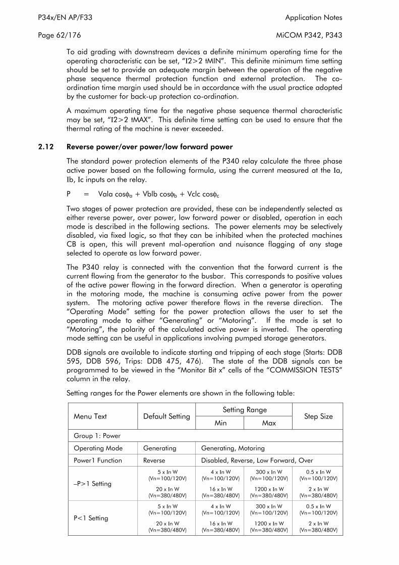
P34x/EN AP/F33 Application Notes
Page 62/176 MiCOM P342, P343
To aid grading with downstream devices a definite minimum operating time for the operating characteristic can be set, “Ι2>2 tMIN”. This definite minimum time setting should be set to provide an adequate margin between the operation of the negative phase sequence thermal protection function and external protection. The coordination time margin used should be in accordance with the usual practice adopted by the customer for back-up protection co-ordination.
A maximum operating time for the negative phase sequence thermal characteristic may be set, “Ι2>2 tMAX”. This definite time setting can be used to ensure that the thermal rating of the machine is never exceeded.
2.12 Reverse power/over power/low forward power
The standard power protection elements of the P340 relay calculate the three phase active power based on the following formula, using the current measured at the Ιa, Ιb, Ιc inputs on the relay.
P = Vala cosφa + Vblb cosφb + Vclc cosφc
Two stages of power protection are provided, these can be independently selected as either reverse power, over power, low forward power or disabled, operation in each mode is described in the following sections. The power elements may be selectively disabled, via fixed logic, so that they can be inhibited when the protected machines CB is open, this will prevent mal-operation and nuisance flagging of any stage selected to operate as low forward power.
The P340 relay is connected with the convention that the forward current is the current flowing from the generator to the busbar. This corresponds to positive values of the active power flowing in the forward direction. When a generator is operating in the motoring mode, the machine is consuming active power from the power system. The motoring active power therefore flows in the reverse direction. The “Operating Mode” setting for the power protection allows the user to set the operating mode to either “Generating” or “Motoring”. If the mode is set to “Motoring”, the polarity of the calculated active power is inverted. The operating mode setting can be useful in applications involving pumped storage generators.
DDB signals are available to indicate starting and tripping of each stage (Starts: DDB 595, DDB 596, Trips: DDB 475, 476). The state of the DDB signals can be programmed to be viewed in the “Monitor Bit x” cells of the “COMMISSION TESTS” column in the relay.
Setting ranges for the Power elements are shown in the following table:
Menu Text Default Setting Setting Range
Step Size Min Max
Group 1: Power
Operating Mode Generating Generating, Motoring
Power1 Function Reverse Disabled, Reverse, Low Forward, Over
–P>1 Setting
5 x Ιn W (Vn=100/120V)
20 x Ιn W (Vn=380/480V)
4 x Ιn W (Vn=100/120V)
16 x Ιn W (Vn=380/480V)
300 x Ιn W (Vn=100/120V)
1200 x Ιn W (Vn=380/480V)
0.5 x Ιn W (Vn=100/120V)
2 x Ιn W (Vn=380/480V)
P<1 Setting
5 x Ιn W (Vn=100/120V)
20 x Ιn W (Vn=380/480V)
4 x Ιn W (Vn=100/120V)
16 x Ιn W (Vn=380/480V)
300 x Ιn W (Vn=100/120V)
1200 x Ιn W (Vn=380/480V)
0.5 x Ιn W (Vn=100/120V)
2 x Ιn W (Vn=380/480V)

Application Notes P34x/EN AP/F33
MiCOM P342, P343 Page 63/176
Menu Text Default Setting Setting Range
Step Size Min Max
Group 1: Power
P>1 Setting
5 x Ιn W (Vn=100/120V)
20 x Ιn W (Vn=380/480V)
4 x Ιn W (Vn=100/120V)
16 x Ιn W (Vn=380/480V)
300 x Ιn W (Vn=100/120V)
1200 x Ιn W (Vn=380/480V)
0.5 x Ιn W (Vn=100/120V)
2 x Ιn W (Vn=380/480V)
Power1 Time Delay 5 s 0 s 100 s 0.1 s
Power1 DO Timer 0 s 0 s 10 s 0.1 s
P1 Poledead Inh Enabled Enabled, Disabled
Power2 Function Low Forward Disabled, Reverse, Low Forward, Over
–P>2 Setting
5 x Ιn W (Vn=100/120V)
20 x Ιn W (Vn=380/480V)
4 x Ιn W (Vn=100/120V)
16 x Ιn W (Vn=380/480V)
300 x Ιn W (Vn=100/120V)
1200 x Ιn W (Vn=380/480V)
0.5 x Ιn W (Vn=100/120V)
2 x Ιn W (Vn=380/480V)
P<2 Setting
5 x Ιn W (Vn=100/120V)
20 x Ιn W (Vn=380/480V)
4 x Ιn W (Vn=100/120V)
16 x Ιn W (Vn=380/480V)
300 x Ιn W (Vn=100/120V)
1200 x Ιn W (Vn=380/480V)
0.5 x Ιn W (Vn=100/120V)
2 x Ιn W (Vn=380/480V)
P>2 Setting
5 x Ιn W (Vn=100/120V)
20 x Ιn W (Vn=380/480V)
4 x Ιn W (Vn=100/120V)
16 x Ιn W (Vn=380/480V)
300 x Ιn W (Vn=100/120V)
1200 x Ιn W (Vn=380/480V)
0.5 x Ιn W (Vn=100/120V)
2 x Ιn W (Vn=380/480V)
Power2 Time Delay 5 s 0 s 100 s 0.1 s
Power2 DO Timer 0 s 0 s 10 s 0.1 s
P2 Poledead Inh Enabled Enabled, Disabled
2.12.1 Sensitive power protection function
The minimum standard 3 phase power protection setting (2%Pn for P342/P343) can be restrictive for some applications. For example for steam turbine generators and some hydro generators a reverse power setting as low as 0.5%Pn is required. A sensitive setting for low forward power protection may also be required, especially for steam turbine generators which have relatively low over speed design limits.
If a power setting less than 2% Pn is required then the sensitive power protection should be used.
To improve the power protection sensitivity, a sensitive CT input is used. The CT input is the same as that of the sensitive earth fault and restricted earth fault protection elements, so the user can only select either sensitive power or SEF/REF in the “Configuration” menu, but not both.
The sensitive power protection measures only A-phase active power, as the abnormal power condition is a 3-phase phenomenon. Having a separate CT input also means that a correctly loaded metering class CT can be used which can provide the required angular accuracy for the sensitive power protection function. A compensation angle setting θC is also be provided to compensate for the angle error introduced by the system CT and VT.
The A-phase power is calculated based on the following formula:
PA = ΙA VA cos (φ - θC)
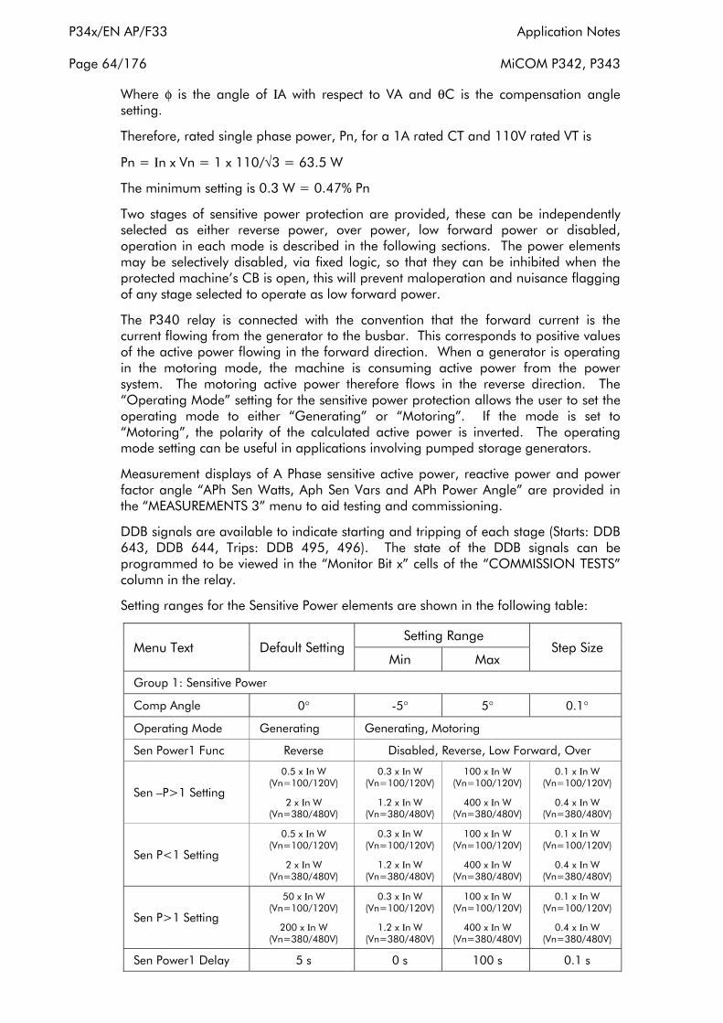
P34x/EN AP/F33 Application Notes
Page 64/176 MiCOM P342, P343
Where φ is the angle of ΙA with respect to VA and θC is the compensation angle setting.
Therefore, rated single phase power, Pn, for a 1A rated CT and 110V rated VT is
Pn = Ιn x Vn = 1 x 110/√3 = 63.5 W
The minimum setting is 0.3 W = 0.47% Pn
Two stages of sensitive power protection are provided, these can be independently selected as either reverse power, over power, low forward power or disabled, operation in each mode is described in the following sections. The power elements may be selectively disabled, via fixed logic, so that they can be inhibited when the protected machine’s CB is open, this will prevent maloperation and nuisance flagging of any stage selected to operate as low forward power.
The P340 relay is connected with the convention that the forward current is the current flowing from the generator to the busbar. This corresponds to positive values of the active power flowing in the forward direction. When a generator is operating in the motoring mode, the machine is consuming active power from the power system. The motoring active power therefore flows in the reverse direction. The “Operating Mode” setting for the sensitive power protection allows the user to set the operating mode to either “Generating” or “Motoring”. If the mode is set to “Motoring”, the polarity of the calculated active power is inverted. The operating mode setting can be useful in applications involving pumped storage generators.
Measurement displays of A Phase sensitive active power, reactive power and power factor angle “APh Sen Watts, Aph Sen Vars and APh Power Angle” are provided in the “MEASUREMENTS 3” menu to aid testing and commissioning.
DDB signals are available to indicate starting and tripping of each stage (Starts: DDB 643, DDB 644, Trips: DDB 495, 496). The state of the DDB signals can be programmed to be viewed in the “Monitor Bit x” cells of the “COMMISSION TESTS” column in the relay.
Setting ranges for the Sensitive Power elements are shown in the following table:
Menu Text Default Setting Setting Range
Step Size Min Max
Group 1: Sensitive Power
Comp Angle 0° -5° 5° 0.1°
Operating Mode Generating Generating, Motoring
Sen Power1 Func Reverse Disabled, Reverse, Low Forward, Over
Sen –P>1 Setting
0.5 x Ιn W (Vn=100/120V)
2 x Ιn W (Vn=380/480V)
0.3 x Ιn W (Vn=100/120V)
1.2 x Ιn W (Vn=380/480V)
100 x Ιn W (Vn=100/120V)
400 x Ιn W (Vn=380/480V)
0.1 x Ιn W (Vn=100/120V)
0.4 x Ιn W (Vn=380/480V)
Sen P<1 Setting
0.5 x Ιn W (Vn=100/120V)
2 x Ιn W (Vn=380/480V)
0.3 x Ιn W (Vn=100/120V)
1.2 x Ιn W (Vn=380/480V)
100 x Ιn W (Vn=100/120V)
400 x Ιn W (Vn=380/480V)
0.1 x Ιn W (Vn=100/120V)
0.4 x Ιn W (Vn=380/480V)
Sen P>1 Setting
50 x Ιn W (Vn=100/120V)
200 x Ιn W (Vn=380/480V)
0.3 x Ιn W (Vn=100/120V)
1.2 x Ιn W (Vn=380/480V)
100 x Ιn W (Vn=100/120V)
400 x Ιn W (Vn=380/480V)
0.1 x Ιn W (Vn=100/120V)
0.4 x Ιn W (Vn=380/480V)
Sen Power1 Delay 5 s 0 s 100 s 0.1 s

Application Notes P34x/EN AP/F33
MiCOM P342, P343 Page 65/176
Menu Text Default Setting Setting Range
Step Size Min Max
Group 1: Sensitive Power
Power1 DO Timer 0 s 0 s 10 s 0.1 s
P1 Poledead Inh Enabled Enabled, Disabled
Sen Power2 Func Low Forward Disabled, Reverse, Low Forward, Over
Sen –P>2 Setting
0.5 x Ιn W (Vn=100/120V)
2 x Ιn W (Vn=380/480V)
0.3 x Ιn W (Vn=100/120V)
1.2 x Ιn W (Vn=380/480V)
100 x Ιn W (Vn=100/120V)
400 x Ιn W (Vn=380/480V)
0.1 x Ιn W (Vn=100/120V)
0.4 x Ιn W (Vn=380/480V)
Sen P<2 Setting
0.5 x Ιn W (Vn=100/120V)
2 x Ιn W (Vn=380/480V)
0.3 x Ιn W (Vn=100/120V)
1.2 x Ιn W (Vn=380/480V)
100 x Ιn W (Vn=100/120V)
400 x Ιn W (Vn=380/480V)
0.1 x Ιn W (Vn=100/120V)
0.4 x Ιn W (Vn=380/480V)
Sen P>2 Setting
50 x Ιn W (Vn=100/120V)
200 x Ιn W (Vn=380/480V)
0.3 x Ιn W (Vn=100/120V)
1.2 x Ιn W (Vn=380/480V)
100 x Ιn W (Vn=100/120V)
400 x Ιn W (Vn=380/480V)
0.1 x Ιn W (Vn=100/120V)
0.4 x Ιn W (Vn=380/480V)
Sen Power2 Delay 2 s 0 s 100 s 0.1 s
Power2 DO Timer 0 s 0 s 10 s 0.1 s
P2 Poledead Inh Enabled Enabled, Disabled
2.12.2 Low forward power protection function
When the machine is generating and the CB connecting the generator to the system is tripped, the electrical load on the generator is cut. This could lead to generator over-speed if the mechanical input power is not reduced quickly. Large turbo-alternators, with low-inertia rotor designs, do not have a high over speed tolerance. Trapped steam in the turbine, downstream of a valve that has just closed, can rapidly lead to over speed. To reduce the risk of over speed damage to such sets, it is sometimes chosen to interlock non-urgent tripping of the generator breaker and the excitation system with a low forward power check. This ensures that the generator set circuit breaker is opened only when the output power is sufficiently low that over speeding is unlikely. The delay in electrical tripping, until prime mover input power has been removed, may be deemed acceptable for ‘non-urgent’ protection trips; e.g. stator earth fault protection for a high impedance earthed generator. For ‘urgent’ trips, e.g. stator current differential protection the low forward power interlock should not be used. With the low probability of ‘urgent’ trips, the risk of over speed and possible consequences must be accepted.
The low forward power protection can be arranged to interlock ‘non-urgent’ protection tripping using the relay scheme logic. It can also be arranged to provide a contact for external interlocking of manual tripping, if desired.
To prevent unwanted relay alarms and flags, a low forward power protection element can be disabled when the circuit breaker is opened via ‘poledead’ logic.
The low forward power protection can also be used to provide loss of load protection when a machine is motoring. It can be used for example to protect a machine which is pumping from becoming unprimed or to stop a motor in the event of a failure in the mechanical transmission. A typical application would be for pump storage generators operating in the motoring mode, where there is a need to prevent the machine becoming unprimed which can cause blade and runner cavitation. During motoring conditions, it is typical for the relay to switch to another setting group with

P34x/EN AP/F33 Application Notes
Page 66/176 MiCOM P342, P343
the low forward power enabled and correctly set and the protection operating mode set to Motoring.
2.12.2.1Low forward power setting guideline
Each stage of power protection can be selected to operate as a low forward power stage by selecting the “Power1 Function/Sen Power1 Func” or “Power2 Function/Sen Power 2 Func” cell to ‘Low Forward’.
When required for interlocking of non urgent tripping applications, the threshold setting of the low forward power protection function, “P<1 Setting/Sen P<1 Setting” or “P<2 Setting/Sen P<2 Setting”, should be less than 50% of the power level that could result in a dangerous over speed transient on loss of electrical loading. The generator set manufacturer should be consulted for a rating for the protected machine. The operating mode should be set to “Generating” for this application.
When required for loss of load applications, the threshold setting of the low forward power protection function, “P<1 Setting/Sen P<1 Setting” or “P<2 Setting/Sen P<2 Setting”, is system dependent, however, it is typically set to 10-20% below the minimum load. For example, for a minimum load of 70%Pn, the setting needs to be set at 63%-56%Pn. The operating mode should be set to “Motoring” for this application.
For interlocking non urgent trip applications the time delay associated with the low forward power protection function, “Power1 TimeDelay/Sen Power1 Delay” or “Power2 TimeDelay/Sen Power2 Delay”, could be set to zero. However, some delay is desirable so that permission for a non-urgent electrical trip is not given in the event of power fluctuations arising from sudden steam valve/throttle closure. A typical time delay for this reason is 2s.
For loss of load applications the pick up time delay, “Power1 TimeDelay/Sen Power1 Delay” or “Power2 TimeDelay/Sen Power2 Delay”, is application dependent but is normally set in excess of the time between motor starting and the load being established. Where rated power can not be reached during starting (for example where the motor is started with no load connected) and the required protection operating time is less than the time for load to be established then it will be necessary to inhibit the power protection during this period. This can be done in the PSL using AND logic and a pulse timer triggered from the motor starting to block the power protection for the required time.
The delay on reset timer, “Power1 DO Timer” or “Power2 DO Timer”, would normally be set to zero when selected to operate low forward power elements.
To prevent unwanted relay alarms and flags, a low forward power protection element can be disabled when the circuit breaker is open via ‘poledead’ logic. This is controlled by setting the power protection inhibit cells, “P1 Poledead Inh” or “P2 Poledead Inh”, to ‘Enabled’.
2.12.3 Reverse power protection function
A generator is expected to supply power to the connected system in normal operation. If the generator prime mover fails, a generator that is connected in parallel with another source of electrical supply will begin to ‘motor’. This reversal of power flow due to loss of prime mover can be detected by the reverse power element.
The consequences of generator motoring and the level of power drawn from the power system will be dependent on the type of prime mover. Typical levels of motoring power and possible motoring damage that could occur for various types of generating plant are given in the following table.
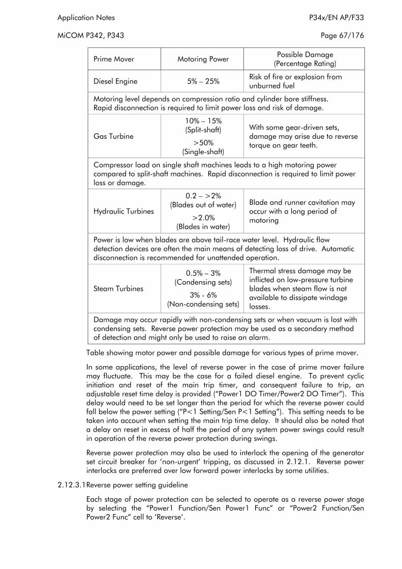
Application Notes P34x/EN AP/F33
MiCOM P342, P343 Page 67/176
Prime Mover Motoring Power Possible Damage (Percentage Rating)
Diesel Engine 5% – 25% Risk of fire or explosion from unburned fuel
Motoring level depends on compression ratio and cylinder bore stiffness. Rapid disconnection is required to limit power loss and risk of damage.
Gas Turbine
10% – 15% (Split-shaft)
>50% (Single-shaft)
With some gear-driven sets, damage may arise due to reverse torque on gear teeth.
Compressor load on single shaft machines leads to a high motoring power compared to split-shaft machines. Rapid disconnection is required to limit power loss or damage.
Hydraulic Turbines
0.2 – >2% (Blades out of water)
>2.0% (Blades in water)
Blade and runner cavitation may occur with a long period of motoring
Power is low when blades are above tail-race water level. Hydraulic flow detection devices are often the main means of detecting loss of drive. Automatic disconnection is recommended for unattended operation.
Steam Turbines
0.5% – 3% (Condensing sets)
3% - 6% (Non-condensing sets)
Thermal stress damage may be inflicted on low-pressure turbine blades when steam flow is not available to dissipate windage losses.
Damage may occur rapidly with non-condensing sets or when vacuum is lost with condensing sets. Reverse power protection may be used as a secondary method of detection and might only be used to raise an alarm.
Table showing motor power and possible damage for various types of prime mover.
In some applications, the level of reverse power in the case of prime mover failure may fluctuate. This may be the case for a failed diesel engine. To prevent cyclic initiation and reset of the main trip timer, and consequent failure to trip, an adjustable reset time delay is provided (“Power1 DO Timer/Power2 DO Timer”). This delay would need to be set longer than the period for which the reverse power could fall below the power setting (“P<1 Setting/Sen P<1 Setting”). This setting needs to be taken into account when setting the main trip time delay. It should also be noted that a delay on reset in excess of half the period of any system power swings could result in operation of the reverse power protection during swings.
Reverse power protection may also be used to interlock the opening of the generator set circuit breaker for ‘non-urgent’ tripping, as discussed in 2.12.1. Reverse power interlocks are preferred over low forward power interlocks by some utilities.
2.12.3.1Reverse power setting guideline
Each stage of power protection can be selected to operate as a reverse power stage by selecting the “Power1 Function/Sen Power1 Func” or “Power2 Function/Sen Power2 Func” cell to ‘Reverse’.

P34x/EN AP/F33 Application Notes
Page 68/176 MiCOM P342, P343
The power threshold setting of the reverse power protection, “-P>1 Setting/Sen -P>1 Setting” or “-P>2 Setting/Sen -P>2 Setting”, should be less than 50% of the motoring power, typical values for the level of reverse power for generators are given in previous table.
For applications to detect the loss of the prime mover or for applications to provide interlocking of non urgent trips the reverse power protection operating mode should be set to “Generating”.
The reverse power protection function should be time-delayed to prevent false trips or alarms being given during power system disturbances or following synchronisation. A time delay setting, “Power1 TimeDelay/Sen Power1 Delay” or “Power2 TimeDelay/Sen Power2 Delay” of 5s should be applied typically.
The delay on reset timer, “Power1 DO Timer” or “Power2 DO Timer”, would normally be set to zero. When settings of greater than zero are used for the reset time delay, the pick up time delay setting may need to be increased to ensure that false tripping does not result in the event of a stable power swinging event.
2.12.4 Over power protection
The overpower protection can be used as overload indication, as a back-up protection for failure of governor and control equipment, and would be set above the maximum power rating of the machine.
2.12.4.1Over power setting guideline
Each stage of power protection can be selected to operate as an over power stage by selecting the “Power1 Function/Sen Power1 Func” or “Power2 Function/Sen Power2 Func” cell to ‘Over’.
The power threshold setting of the over power protection, “P>1 Setting/Sen P>1 Setting” or “P>2 Setting/Sen P>2 Setting”, should be set greater than the machine full load rated power.
A time delay setting, “Power1 TimeDelay/Sen Power1 Delay” or “Power2 TimeDelay/Sens Power2 Delay” should be applied.
The operating mode should be set to “Motoring” or “Generating” depending on the operating mode of the machine.
The delay on reset timer, “Power1 DO Timer” or “Power2 DO Timer”, would normally be set to zero.
2.13 Stator earth fault protection function
Low voltage generators will be solidly earthed, however to limit the damage that can be caused due to earth faults, it is common for HV generators to be connected to earth via an impedance. This impedance may be fitted on the secondary side of a distribution transformer earthing arrangement. The earthing impedance is generally chosen to limit earth fault current to full load current or less.
There is a limit on the percentage of winding that can be protected by a stator earth fault element. For earth faults close to the generator neutral, the driving voltage will be low, and hence the value of fault current will be severely reduced. In practice, approximately 95% of the stator winding can be protected. For faults in the last 5% of the winding, the earth fault current is so low that it cannot be detected by this type of earth fault protection. In most applications this limitation is accepted as the chances of an earth fault occurring in the last 5% of the winding, where the voltage to earth is low, is small.

Application Notes P34x/EN AP/F33
MiCOM P342, P343 Page 69/176
The percentage of winding covered by the earth fault protection can be calculated as shown below, with reference to Figure 19.
Figure 19: Effective coverage of stator earth fault protection
A two stage non-directional earth fault element is provided. The first stage has an inverse time or definite time delay characteristic and can incorporate a reset time delay to improve detection of intermittent faults. The second stage has a definite time characteristic which can be set to 0s to provide instantaneous operation.
Where impedance or distribution transformer earthing is used the second stage of protection may be used to detect flashover of the earthing impedance. The second stage may also be used to provide instantaneous protection where grading with system protection is not required. See setting guidelines for more details.
Each stage of protection can be blocked by energising the relevant DDB signal via the PSL (DDB 358, DDB 359). This allows the earth fault protection to be integrated into busbar protection schemes as shown in section 2.24, or can be used to improve grading with downstream devices. DDB signals are also available to indicate the start and trip of each stage of protection, (Starts: DDB 613, DDB 614, Trips: DDB 442, DDB 443). The state of the DDB signals can be programmed to be viewed in the “Monitor Bit x” cells of the “COMMISSION TESTS” column in the relay.
The Stator Earth Fault element is powered from the IN CT input on the relay. This input should be supplied from a CT fitted into the generator earth path so that the element provides earth fault protection for the generator and back-up protection for system faults. Alternatively, the element may be supplied from a CT fitted on the secondary side of a distribution transformer earthing system.

P34x/EN AP/F33 Application Notes
Page 70/176 MiCOM P342, P343
Setting ranges and default settings for this element are shown in the following table:
Menu Text Default Setting Setting Range
Step Size Min Max
GROUP 1 EARTH FAULT
ΙN>1 Function Disabled
Disabled, DT, IEC S Inverse, IEC V Inverse, IEC E Inverse, UK LT Inverse, RI,
IEEE M Inverse, IEEE V Inverse, IEEE E Inverse, US Inverse,
US ST Inverse, IDG
ΙN>1 Current 0.1 x Ιn A 0.02 x Ιn A 4 x Ιn A 0.01 x Ιn A
ΙN1>1 IDG Ιs 1.5 1 4 0.1
ΙN>1 Time Delay 1 s 0 s 200 s 0.01 s
ΙN>1 TMS 1 0.025 1.2 0.025
ΙN>1 Time Dial 1 0.01 100 0.01
ΙN>1 K(RI) 1 0.1 10 0.05
ΙN>1 IDG Time 1.2 1 2 0.01
ΙN>1 Reset Char DT DT, Inverse N/A
ΙN>1 tRESET 0 s 0 s 100 s 0.01 s
ΙN>2 Function DT Disabled, DT N/A
ΙN>2 Current Set 0.45 x Ιn A 0.02 x Ιn A 10 x Ιn A 0.01 x Ιn A
ΙN>2 Time Delay 0 s 0 s 200 s 0.01 s
For further details regarding the inverse time characteristics refer to the Overcurrent Protection, section 2.4.
2.13.1 IDG curve
The IDG curve is commonly used for time delayed earth fault protection in the Swedish market. This curve is available in stages 1 and 2 of Earth Fault protection.
The IDG curve is represented by the following equation:
t = 5.8 - 1.35 loge
ΙΙN > Setting in seconds
where
Ι = measured current
ΙN>Setting = an adjustable setting which defines the start point of the characteristic
Although the start point of the characteristic is defined by the “ΙN>” setting, theactual relay current threshold is a different setting called “IDG Ιs”. The “IDG Ιs”setting is set as a multiple of “ΙN>”.
An additional setting “IDG Time” is also used to set the minimum operating time athigh levels of fault current.
Figure 20 illustrates how the IDG characteristic is implemented.
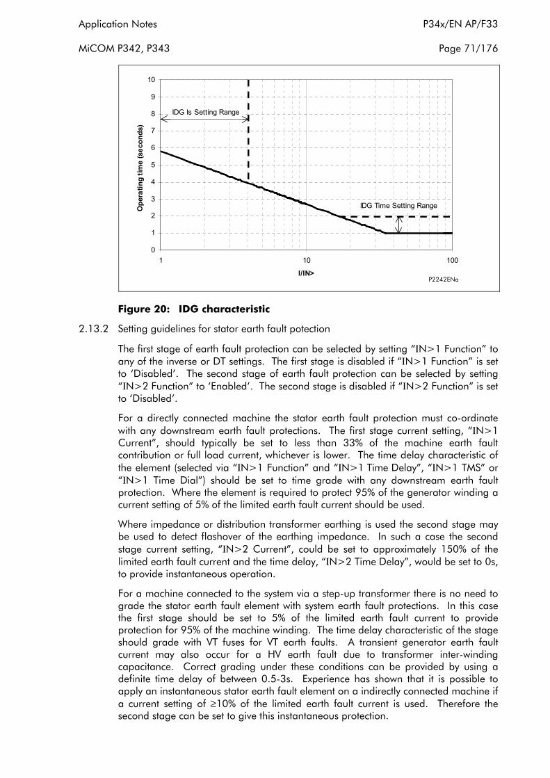
Application Notes P34x/EN AP/F33
MiCOM P342, P343 Page 71/176
0
1
2
3
4
5
6
7
8
9
10
1 10 100
I/IN>
Ope
ratin
g tim
e (s
econ
ds)
IDG Is Setting Range
IDG Time Setting Range
P2242ENa
Figure 20: IDG characteristic
2.13.2 Setting guidelines for stator earth fault potection
The first stage of earth fault protection can be selected by setting “ΙN>1 Function” to any of the inverse or DT settings. The first stage is disabled if “ΙN>1 Function” is set to ‘Disabled’. The second stage of earth fault protection can be selected by setting “ΙN>2 Function” to ‘Enabled’. The second stage is disabled if “ΙN>2 Function” is set to ‘Disabled’.
For a directly connected machine the stator earth fault protection must co-ordinate with any downstream earth fault protections. The first stage current setting, “ΙN>1 Current”, should typically be set to less than 33% of the machine earth fault contribution or full load current, whichever is lower. The time delay characteristic of the element (selected via “ΙN>1 Function” and “ΙN>1 Time Delay”, “ΙN>1 TMS” or “ΙN>1 Time Dial”) should be set to time grade with any downstream earth fault protection. Where the element is required to protect 95% of the generator winding a current setting of 5% of the limited earth fault current should be used.
Where impedance or distribution transformer earthing is used the second stage may be used to detect flashover of the earthing impedance. In such a case the second stage current setting, “ΙN>2 Current”, could be set to approximately 150% of the limited earth fault current and the time delay, “ΙN>2 Time Delay”, would be set to 0s, to provide instantaneous operation.
For a machine connected to the system via a step-up transformer there is no need to grade the stator earth fault element with system earth fault protections. In this case the first stage should be set to 5% of the limited earth fault current to provide protection for 95% of the machine winding. The time delay characteristic of the stage should grade with VT fuses for VT earth faults. A transient generator earth fault current may also occur for a HV earth fault due to transformer inter-winding capacitance. Correct grading under these conditions can be provided by using a definite time delay of between 0.5-3s. Experience has shown that it is possible to apply an instantaneous stator earth fault element on a indirectly connected machine if a current setting of ≥10% of the limited earth fault current is used. Therefore the second stage can be set to give this instantaneous protection.

P34x/EN AP/F33 Application Notes
Page 72/176 MiCOM P342, P343
2.14 Residual overvoltage/neutral voltage displacement protection function
On a healthy three phase power system, the addition of each of the three phase to earth voltages is nominally zero, as it is the vector addition of three balanced vectors at 120° to one another. However, when an earth fault occurs on the primary system this balance is upset and a ‘residual’ voltage is produced.
This could be measured, for example, at the secondary terminals of a voltage transformer having a “broken delta” secondary connection. Hence, a residual voltage measuring relay can be used to offer earth fault protection on such a system. Note that this condition causes a rise in the neutral voltage with respect to earth which is commonly referred to as “neutral voltage displacement” or NVD.
Alternatively, if the system is impedance or distribution transformer earthed, the neutral displacement voltage can be measured directly in the earth path via a single phase VT. This type of protection can be used to provide earth fault protection irrespective of whether the generator is earthed or not, and irrespective of the form of earthing and earth fault current level. For faults close to the generator neutral the resulting residual voltage will be small. Therefore, as with stator earth fault protection, only 95% of the stator winding can be reliably protected.
It should be noted that where residual overvoltage protection is applied to a directly connected generator, such a voltage will be generated for an earth fault occurring anywhere on that section of the system and hence the NVD protection must coordinate with other earth fault protections.
The neutral voltage displacement protection function of the P340 relay consists of two stages with adjustable time delays.
Two stages are included for the element to account for applications which require both alarm and trip stages, for example, an insulated system. It is common in such a case for the system to have been designed to withstand the associated healthy phase overvoltages for a number of hours following an earth fault. In such applications, an alarm is generated soon after the condition is detected, which serves to indicate the presence of an earth fault on the system. This gives time for system operators to locate and isolate the fault. The second stage of the protection can issue a trip signal if the fault condition persists.
A dedicated voltage input is provided for this protection function, this may be used to measure the residual voltage supplied from either an open delta connected VT or the voltage measured on the secondary side of a distribution transformer earth connection, as shown in Figure 21. Alternatively, the residual voltage may be derived internally from the three phase to neutral voltage measurements. Where derived measurement is used the 3 phase to neutral voltage must be supplied from either a 5-limb or three single phase VTs. These types of VT design allow the passage of residual flux and consequently permit the relay to derive the required residual voltage. In addition, the primary star point of the VT must be earthed. A three limb VT has no path for residual flux and is therefore unsuitable to supply the relay when residual voltage is required to be derived from the phase to neutral voltage measurement.
The residual voltage signal also provides a polarising voltage signal for the sensitive directional earth fault protection function.
Application Notes P34x/EN AP/F33
MiCOM P342, P343 Page 73/176
Figure 21: Alternative relay connections for residual overvoltage/NVD protection
Each stage of protection can be blocked by energising the relevant DDB signal via the PSL (DDB 368, DDB 369), this can be used to improve grading with downstream devices. DDB signals are also available to indicate the start and trip of each stage of protection, (Starts: DDB 577, DDB 578, Trips: DDB 451, DDB 452). The state of the DDB signals can be programmed to be viewed in the “Monitor Bit x” cells of the “COMMISSION TESTS” column in the relay.
Setting ranges and default settings for this element are shown in the following table:
Menu Text Default Setting Setting Range
Step Size Min Max
GROUP 1 RESIDUAL O/V NVD
VN Input Measured Measured, Derived
VN>1 Function DT Disabled, DT, IDMT
VN>1 Voltage Set 5V (Vn=100/120V)
20V (Vn=380/480V)
1V (Vn=100/120V)
4V (Vn=380/480V)
80V (Vn=100/120V)
320V (Vn=380/480V)
1V (Vn=100/120V)
4V (Vn=380/480V)
VN>1 Time Delay 1 s 0 s 100 s 0.01 s
VN>1 TMS 1 0.5 100 0.5
VN>1 tRESET 0 s 0 s 100 s 0.01 s
VN>2 Status DT Disabled or DT
P34x/EN AP/F33 Application Notes
Page 74/176 MiCOM P342, P343
Menu Text Default Setting Setting Range
Step Size Min Max
GROUP 1 RESIDUAL O/V NVD
VN>2 Voltage Set 5V (Vn=100/120V)
20V (Vn=380/480V)
1V (Vn=100/120V)
4V (Vn=380/480V)
80V (Vn=100/120V)
320V (Vn=380/480V)
1V (Vn=100/120V)
4V (Vn=380/480V)
VN>2 Time Delay 0 s 0 s 100 s 0.01 s
The IDMT characteristic available on the first stage is defined by the following formula:
t = K / (M – 1)
where
K = Time Multiplier Setting (“VN>1 TMS”)
t = Operating Time in Seconds
M = Measured Residual Voltage/Relay Setting Voltage (“VN>1 Voltage Set”)
2.14.1 Setting guidelines for residual overvoltage/neutral voltage displacement protection
Stage 1 may be selected as either ‘IDMT’ (inverse time operating characteristic), ‘DT’ (definite time operating characteristic) or ‘Disabled’, within the “VN>1 Function” cell. Stage 2 operates with a definite time characteristic and is Enabled/Disabled in the “VN>2 Status” cell. The time delay. (“VN>1 TMS” - for IDMT curve; “V>1 Time Delay”, “V>2 Time Delay”- for definite time) should be selected in accordance with normal relay co-ordination procedures to ensure correct discrimination for system faults.
The residual overvoltage protection can be set to operate from the voltage measured at the Vn input VT terminals or the residual voltage derived from the phase-neutral voltage inputs as selected by “VN Input”.
For a directly connected machine the neutral voltage displacement protection must co-ordinate with any downstream earth fault protections. To ensure co-ordination the voltage setting of the neutral voltage displacement protection function should be set higher than the effective setting of current operated earth fault protection in the same earth fault zone. The effective voltage setting of a current operated earth fault protection may be established from the following equations:
Veff = (Ιpoc x Ze) / (1/3 x V1/V2) for an open delta VT
Veff = (Ιpoc x Ze) / (V1/V2) for a single phase star point VT
where
Veff = effective voltage setting of current operated protection
Ιpoc = primary operating current of current operated protection
Ze = earthing impedance
V1/V2 = VT turns ratio

Application Notes P34x/EN AP/F33
MiCOM P342, P343 Page 75/176
It must also be ensured that the voltage setting of the element is set above any standing level of residual voltage that is present on the system. A typical setting for residual overvoltage protection is 5V.
The second stage of protection can be used as an alarm stage on unearthed or very high impedance earthed systems where the system can be operated for an appreciable time under an earth fault condition.
Where the generator is connected to the system via a transformer, co-ordination with system earth fault protections is not required. In these applications the NVD voltage setting should typically be set to 5% of rated voltage. This will provide protection for 95% of the stator winding.
2.15 Sensitive earth fault protection function
If a generator is earthed through a high impedance, or is subject to high ground fault resistance, the earth fault level will be severely limited. Consequently, the applied earth fault protection requires both an appropriate characteristic and a suitably sensitive setting range in order to be effective. A separate sensitive earth fault element is provided within the P340 relay for this purpose, this has a dedicated CT input allowing very low current setting thresholds to be used.
An alternative use for the sensitive earth fault input is on a multiple earthed system where it is advantageous to apply a directional earth fault relay at the machine terminals. The directional relay, operating for current flowing into the machine, will be stable for external faults but can operate quickly for generator faults when fault current is fed from the system.
Where several machines are connected in parallel, it is common for only one machine to be earthed at any time. This prevents the flow of third harmonic currents which could overheat the machine. This may be the only earth connection for this part of the system. Non directional earth fault protection could be applied at the terminals of the unearthed machines in such cases since an unearthed generator cannot source earth fault current. However, as any of the machines can be earthed, it is prudent to apply directional protection at the terminals of all the machines. There is also a risk that transient spill current can cause operation of a non directional, terminal fed, earth fault relay for an external phase fault, hence directional elements have an added degree of security. When applied in this way the directional earth fault elements will operate for faults on the unearthed machines but not the earthed machine. Therefore, additional stator earth fault or residual overvoltage/NVD protection should be used to protect the earthed machine. Such a scheme will provide stable, fast, earth fault protection for all machines, no matter which generator is earthed.
A single stage definite time sensitive earth fault protection element is provided in the P340 relay, this element can be set to operate with a directional characteristic when required. When directional earth fault protection is required the operating current should be derived from either a core balanced CT or the residual connection of 3 phase CTs at the terminals of the machine. Direction of the earth fault current for this element is determined with reference to the polarising signal, the residual voltage. The polarising signal is taken from the residual overvoltage/NVD protection input or derived from the 3 phase-neutral voltage inputs on the relay.
A polarising voltage threshold is also provided. The element cannot operate unless voltage exceeds this threshold. This helps to restrain the element during phase/phase faults when transient CT saturation produces spill current in the residual connection of the phase CTs. No residual voltage will be present during such non earth fault conditions hence the DEF element cannot operate. The element will therefore be
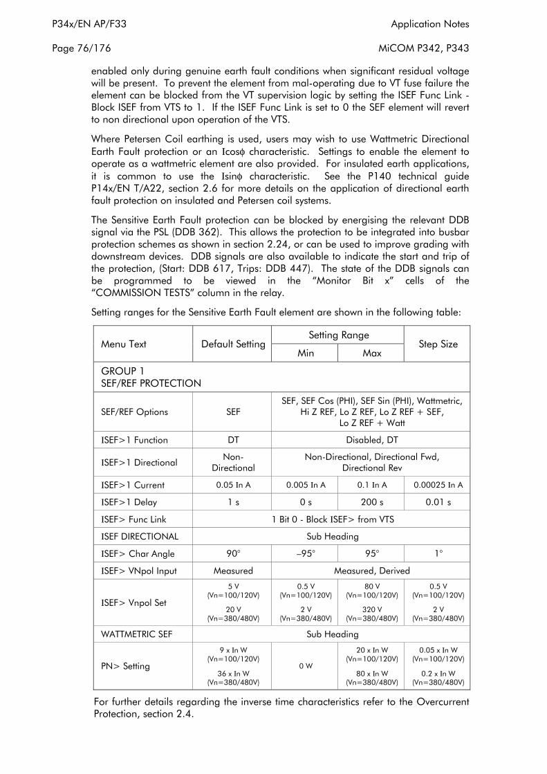
P34x/EN AP/F33 Application Notes
Page 76/176 MiCOM P342, P343
enabled only during genuine earth fault conditions when significant residual voltage will be present. To prevent the element from mal-operating due to VT fuse failure the element can be blocked from the VT supervision logic by setting the ISEF Func Link Block ISEF from VTS to 1. If the ISEF Func Link is set to 0 the SEF element will revert to non directional upon operation of the VTS.
Where Petersen Coil earthing is used, users may wish to use Wattmetric Directional Earth Fault protection or an Ιcosφ characteristic. Settings to enable the element to operate as a wattmetric element are also provided. For insulated earth applications, it is common to use the Ιsinφ characteristic. See the P140 technical guide P14x/EN T/A22, section 2.6 for more details on the application of directional earth fault protection on insulated and Petersen coil systems.
The Sensitive Earth Fault protection can be blocked by energising the relevant DDB signal via the PSL (DDB 362). This allows the protection to be integrated into busbar protection schemes as shown in section 2.24, or can be used to improve grading with downstream devices. DDB signals are also available to indicate the start and trip of the protection, (Start: DDB 617, Trips: DDB 447). The state of the DDB signals can be programmed to be viewed in the “Monitor Bit x” cells of the “COMMISSION TESTS” column in the relay.
Setting ranges for the Sensitive Earth Fault element are shown in the following table:
Menu Text Default Setting Setting Range
Step Size Min Max
GROUP 1 SEF/REF PROTECTION
SEF/REF Options SEF SEF, SEF Cos (PHI), SEF Sin (PHI), Wattmetric,
Hi Z REF, Lo Z REF, Lo Z REF + SEF, Lo Z REF + Watt
ΙSEF>1 Function DT Disabled, DT
ΙSEF>1 Directional Non-
Directional Non-Directional, Directional Fwd,
Directional Rev
ΙSEF>1 Current 0.05 Ιn A 0.005 Ιn A 0.1 Ιn A 0.00025 Ιn A
ΙSEF>1 Delay 1 s 0 s 200 s 0.01 s
ΙSEF> Func Link 1 Bit 0 - Block ΙSEF> from VTS
ΙSEF DIRECTIONAL Sub Heading
ΙSEF> Char Angle 90° –95° 95° 1°
ΙSEF> VNpol Input Measured Measured, Derived
ΙSEF> Vnpol Set
5 V (Vn=100/120V)
20 V (Vn=380/480V)
0.5 V (Vn=100/120V)
2 V (Vn=380/480V)
80 V (Vn=100/120V)
320 V (Vn=380/480V)
0.5 V (Vn=100/120V)
2 V (Vn=380/480V)
WATTMETRIC SEF Sub Heading
PN> Setting
9 x Ιn W (Vn=100/120V)
36 x Ιn W (Vn=380/480V)
0 W
20 x Ιn W (Vn=100/120V)
80 x Ιn W (Vn=380/480V)
0.05 x Ιn W (Vn=100/120V)
0.2 x Ιn W (Vn=380/480V)
For further details regarding the inverse time characteristics refer to the Overcurrent Protection, section 2.4.

Application Notes P34x/EN AP/F33
MiCOM P342, P343 Page 77/176
2.15.1 Setting guidelines for sensitive earth fault protection
The operating function of the sensitive earth fault protection can be selected by setting “SEF/REF Options” cell. The SEF protection is selected by setting “ΙSEF>1 Function” to ‘Enabled’. To provide sensitive earth fault or sensitive directional earth fault protection the “SEF/REF Options” cell should be set to ‘SEF’. For SEF cosφ and SEF sinφ earth fault protection “SEF/REF Options” cell should be set to to ‘SEF Cos (PHI) or SEF Sin (PHI)’. The SEF cosφ and SEF sinφ options are not available with low impedance REF protection. For wattmetric earth fault protection “SEF/REF Options” cell should be set to ‘Wattmetric’. The other options for “SEF/REF Options” relate to restricted earth fault protection, for more details see section 2.16.
The directionality of the element is selected in the “ΙSEF> Direction” setting. If “ΙSEF> Direction” is set to ‘Directional Fwd’ the element will operate with a directional characteristic and will operate when current flows in the forward direction, i.e. when current flows into the machine with the relay connected as shown in the standard relay connection diagram. If “ΙSEF> Direction” is set to ‘Directional Rev’ the element will operate with a directional characteristic and will operate when current flows in the opposite direction, i.e. current flow out of the machine into the system. If “ΙSEF> Direction” is set to ‘Non-Directional’ the element will operate as a simple overcurrent element. If either of the directional options are chosen additional cells to select the characteristic angle of the directional characteristic and polarising voltage threshold will become visible.
The operating current threshold of the Sensitive Earth Fault protection function, “ΙSEF>1 Current”, should be set to give a primary operating current down to 5% or less of the minimum earth fault current contribution to a generator terminal fault.
The directional element characteristic angle setting, “ΙSEF> Char Angle”, should be set to match as closely as possible the angle of zero sequence source impedance behind the relaying point. If this impedance is dominated by an earthing resistor, for example, the angle setting would be set to 0°. On insulated or very high impedance earthed systems the earth fault current measured by a SDEF element is predominantly capacitive hence the RCA should be set to –90°.
The polarising voltage threshold setting, “ΙSEF> VNpol Set”, should be chosen to give a sensitivity equivalent to that of the operating current threshold. This current level can be translated into a residual voltage as described for the residual overvoltage protection in section 2.14.
When the element is set as a non directional element the definite time delay setting “ΙSEF>1 Delay” should be set to co-ordinate with downstream devices that may operate for external earth faults. For an indirectly connected generator the SEF element should co-ordinate with the measurement VT fuses, to prevent operation for VT faults. For directional applications when the element is fed from the residual connection of the phase CTs a short time delay is desirable to ensure stability for external earth faults or phase/phase faults. A time delay of 0.5s will be sufficient to provide stability in the majority of applications. Where a dedicated core balance CT is used for directional applications an instantaneous setting may be used.
2.16 Restricted earth fault protection
Earth faults occurring on a machine winding or terminal may be of limited magnitude, either due to the impedance present in the earth path or by the percentage of stator winding that is involved in the fault. As stated in section 2.13, it is common to apply stator earth fault protection fed from a single CT in the machine earth connection - this can provide time delayed protection for a stator winding or

P34x/EN AP/F33 Application Notes
Page 78/176 MiCOM P342, P343
terminal fault. On larger machines, typically >2MW, where phase CTs can be fitted to both neutral end and terminal ends of the stator winding, phase differential protection may be fitted. For small machines, however, only one set of phase CTs may be available making phase differential protection impractical. For smaller generators earth fault differential protection can be applied to provide instantaneous tripping for any stator or terminal earth fault. In application the operating zone of earth fault differential protection is restricted to faults within the boundaries of the CTs supplying the relay, hence this type of element is referred to as restricted earth fault protection.
When applying differential protection such as REF, some suitable means must be employed to give the protection stability under external fault conditions, thus ensuring that relay operation only occurs for faults on the transformer winding/connections. Two methods are commonly used; percentage bias or high impedance. The biasing technique operates by measuring the level of through current flowing and altering the relay sensitivity accordingly. The high impedance technique ensures that the relay circuit is of sufficiently high impedance such that the differential voltage that may occur under external fault conditions is less than that required to drive setting current through the relay.
The REF protection in the P340 relays may be configured to operate as either a high impedance differential or a low impedance biased differential element. The following sections describe the application of the relay in each mode.
Note that the high impedance REF element of the relay shares the same CT input as the SEF protection. Hence, only one of these elements may be selected.
A DDB signals are also available to indicate the tripping of the REF protection, (DDB 446). The state of the DDB signals can be programmed to be viewed in the “Monitor Bit x” cells of the “COMMISSION TESTS” column in the relay.
The REF settings can be found in the ‘SEF/REF PROT’N’ column and are shown below:
Menu Text Default Setting Setting Range
Step Size Min Max
GROUP 1 SEF/REF PROT'N
SEF/REF Options SEF SEF, Wattmetric, Hi Z REF, Lo Z REF, Lo Z REF + SEF, Lo Z REF + Watt
REF PROTECTION Sub Heading
ΙREF> k1 20% 0 20% 1%
ΙREF> k2 150% 0 150% 1%
ΙREF> Ιs1 0.2 Ιn A 0.05 Ιn A 1 Ιn A 0.01 Ιn A
ΙREF> Ιs2 1 Ιn A 0.1 Ιn A 1.5 Ιn A 0.01 Ιn A
ΙREF> Ιs 0.2 Ιn A 0.05 Ιn A 1 Ιn A 0.01 Ιn A
Note that CT requirements for REF protection are included in section 4.
2.16.1 Low impedance biased differential REF protection
In a biased differential relay, the through current is measured and used to increase the setting of the differential element. For heavy through faults, one CT in the scheme can be expected to become more saturated than the other and hence

Application Notes P34x/EN AP/F33
MiCOM P342, P343 Page 79/176
differential current can be produced. However, biasing will increase the relay setting such that the resulting differential current is insufficient to cause operation of the relay.
Figures 22 and 23 show the appropriate relay connections and operating characteristic for the P340 relay applied for biased REF protection, respectively:
Figure 22: Relay connections for biased REF protection
Figure 23: Biased REF protection operating characteristic

P34x/EN AP/F33 Application Notes
Page 80/176 MiCOM P342, P343
As can be seen in Figure 22, the three line CTs are connected to the three phase CTs in the normal manner. The neutral CT is then connected to the stator earth fault CT input. These currents are then used internally to derive both a bias and a differential current quantity for use by the low impedance biased differential REF protection.
The advantage of this method of connection is that the line and neutral CTs are not differentially connected and so the neutral CT can also be used to drive the stator earth fault protection. Also, no external equipment such as stabilising resistors or metrosils are required, unlike the case with high impedance protection.
The formula used by the relay to calculate the required bias quantity is therefore as follows:
Ιbias = (Highest of Ιa, Ιb or Ιc) + (Ιneutral x Scaling Factor) / 2
The reason for the scaling factor included on the neutral current is explained by referring to Figure 24:
Figure 24: Neutral scaling for biased REF protection
Where it is required that the neutral CT also drives the stator earth fault protection element, it may be a requirement that the neutral CT has a lower ratio than the line CTs in order to provide better earth fault sensitivity. The relay automatically scales the level of neutral current used in the bias calculation by a factor equal to the ratio of the neutral to line CT primary ratings to compensate for any mismatch.

Application Notes P34x/EN AP/F33
MiCOM P342, P343 Page 81/176
2.16.1.1Setting guidelines for low impedance biased REF protection
To select low impedance biased REF protection “SEF/REF Option” should be selected to ‘Lo Z REF’. If REF protection is required to operate alongside sensitive earth fault protection, “SEF/REF Option” should be selected to ‘Lo Z REF + SEF’ or ‘Lo Z REF + Wattmet’ (if Wattmetric earth fault protection is required).
As can be seen from Figure 23, two bias settings are provided in the REF characteristic of the P340. The “ΙREF> k1” level of bias is applied up to through currents of “ΙREF> Ιs2”, which is normally set to the rated current of the machine. “ΙREF> k1” should normally be set to 0% to give optimum sensitivity for internal faults. However, if any differential spill current is present under normal conditions due to CT mismatch, then “ΙREF> k1” may be increased accordingly, to compensate.
“ΙREF> k2” bias is applied for through currents above “ΙREF> Ιs2” and may typically be set to 150% to ensure adequate restraint for external faults.
The neutral current scaling factor which automatically compensates for differences between neutral and phase CT ratios relies upon the relay having been programmed with the correct CT ratios. It must therefore be ensured that these CT ratios are entered into the relay, in the “CT RATIOS” menu, in order for the scheme to operate correctly.
The differential current setting “ΙREF> Ιs1” should typically be set to 5% of the limited earth fault current level.
2.16.2 High impedance restricted earth fault protection
The high impedance principle is best explained by considering a differential scheme where one CT is saturated for an external fault, as shown in Figure 25.
If the relay circuit is considered to be a very high impedance, the secondary current produced by the healthy CT will flow through the saturated CT. If CT magnetising impedance of the saturated CT is considered to be negligible, the maximum voltage across the relay circuit will be equal to the secondary fault current multiplied by the connected impedance, (RL3 + RL4 + RCT2).
The relay can be made stable for this maximum applied voltage by increasing the overall impedance of the relay circuit, such that the resulting current through the relay is less than its current setting. As the impedance of the relay input alone is relatively low, a series connected external resistor is required. The value of this resistor, RST, is calculated by the formula shown in Figure 25.
An additional non linear resistor, metrosil, may be required to limit the peak secondary circuit voltage during internal fault conditions.
To ensure that the protection will operate quickly during an internal fault the CT’s used to operate the protection must have a kneepoint voltage of at least 4Vs.

P34x/EN AP/F33 Application Notes
Page 82/176 MiCOM P342, P343
Figure 25: Principle of high impedance differential protection
Figure 26: Relay connections for high impedance REF protection
Application Notes P34x/EN AP/F33
MiCOM P342, P343 Page 83/176
The necessary relay connections for high impedance REF are shown in Figure 26:
As can be seen from Figure 26, the high impedance protection uses an external differential connection between the line CTs and neutral CT. The SEF input is then connected to the differential circuit with a stabilising resistor in series.
2.16.2.1Setting guidelines for high impedance REF protection
From the “Sens E/F Options” cell, ‘Hi Z REF’ must be selected to enable High Impedance REF protection. The only setting cell then visible is “ΙREF> Ιs”, which may be programmed with the required differential current setting. This would typically be set to give a primary operating current of either 30% of the minimum earth fault level for a resistance earthed system or between 10 and 60% of rated current for a solidly earthed system.
The primary operating current (Ιop) will be a function of the current transformer ratio, the relay operating current (“ΙREF> Ιs”), the number of current transformers in parallel with a relay element (n) and the magnetising current of each current transformer (Ιe) at the stability voltage (Vs). This relationship can be expressed in three ways:
1. To determine the maximum current transformer magnetising current to achieve a specific primary operating current with a particular relay operating current.
Ι- Gen diff REF > Ιs1
1 op Ι < xe n CT ratio
2. To determine the maximum relay current setting to achieve a specific primary operating current with a given current transformer magnetising current.
ΙREF Ιs1 < Ιop
- nΙCT ratio e
3. To express the protection primary operating current for a particular relay operating current and with a particular level of magnetising current.
Ιop = (CT ratio) x (ΙREF > Ιs1 + nΙe)
In order to achieve the required primary operating current with the current transformers that are used, a current setting “ΙREF> Ιs” must be selected for the high impedance element, as detailed in expression (ii) above. The setting of the stabilising resistor (RST) must be calculated in the following manner, where the setting is a function of the required stability voltage setting (VS) and the relay current setting “ΙREF> Ιs”.
Vs 0.7 ΙF (RCT + 2RL) = =RST ΙREF > Ιs1 ΙREF > Ιs1
See Figure 25 for reference.
Note: The above equation assumes negligible relay impedance.
The stabilising resistor supplied is continuously adjustable up to its maximum declared resistance.
P34x/EN AP/F33 Application Notes
Page 84/176 MiCOM P342, P343
USE OF “METROSIL” NON-LINEAR RESISTORS
Metrosils are used to limit the peak voltage developed by the current transformers under internal fault conditions, to a value below the insulation level of the current transformers, relay and interconnecting leads, which are normally able to withstand 3000V peak.
The following formulae should be used to estimate the peak transient voltage that could be produced for an internal fault. The peak voltage produced during an internal fault will be a function of the current transformer kneepoint voltage and the prospective voltage that would be produced for an internal fault if current transformer saturation did not occur. This prospective voltage will be a function of maximum internal fault secondary current, the current transformer ratio, the current transformer secondary winding resistance, the current transformer lead resistance to the common point, the relay lead resistance and the stabilising resistor value.
Vp = 2 2 Vk (Vf - Vk )
Vf = Ι'f (RCT + 2RL + RST)
where
Vp = peak voltage developed by the CT under internal fault conditions.
Vk = current transformer knee-point voltage.
Vf = maximum voltage that would be produced if CT saturation did not occur.
Ι‘f = maximum internal secondary fault current.
RCT = current transformer secondary winding resistance.
RL = maximum lead burden from current transformer to relay.
RST = relay stabilising resistor.
When the value given by the formulae is greater than 3000V peak, metrosils should be applied. They are connected across the relay circuit and serve the purpose of shunting the secondary current output of the current transformer from the relay in order to prevent very high secondary voltages.
Metrosils are externally mounted and take the form of annular discs. Their operating characteristics follow the expression:
V = CΙ 0.25
where
V = Instantaneous voltage applied to the non-linear resistor (“metrosil”)
C = constant of the non-linear resistor (“metrosil”)
Ι = instantaneous current through the non-linear resistor (“metrosil”)
With a sinusoidal voltage applied across the metrosil, the RMS current would be approximately 0.52x the peak current. This current value can be calculated as follows:
Ι(rms) = 0.52 Vs (rms) x 2
C
4
Application Notes P34x/EN AP/F33
MiCOM P342, P343 Page 85/176
where
Vs(rms) = rms value of the sinusoidal voltage applied across the metrosil.
This is due to the fact that the current waveform through the non-linear resistor(“metrosil”) is not sinusoidal but appreciably distorted.
For satisfactory application of a non-linear resistor (“metrosil”), it’s characteristicshould be such that it complies with the following requirements:
1. At the relay voltage setting, the non-linear resistor (“metrosil”) current should be as low as possible, but no greater than approximately 30mA rms for 1A current transformers and approximately 100mA rms for 5A current transformers.
2. At the maximum secondary current, the non-linear resistor (“metrosil”) should limit the voltage to 1500V rms or 2120V peak for 0.25 second. At higher relay voltage settings, it is not always possible to limit the fault voltage to 500V rms, so higher fault voltages may have to be tolerated.
The following tables show the typical Metrosil types that will be required, depending on relay current rating, REF voltage setting etc.
Metrosil Units for Relays with a 1 Amp CT
The Metrosil units with 1 Amp CTs have been designed to comply with the following restrictions:
1. At the relay voltage setting, the Metrosil current should less than 30mA rms
2. At the maximum secondary internal fault current the Metrosil unit should limit the voltage to 1500V rms if possible.
The Metrosil units normally recommended for use with 1Amp CTs are as shown in the following table:
Relay Voltage Setting
Nominal Characteristic Recommended Metrosil Type
C β Single Pole Relay Triple Pole Relay
Up to 125V rms 450 0.25 600A/S1/S256 600A/S3/1/S802
125 to 300V rms 900 0.25 600A/S1/S1088 600A/S3/1/S1195
Note: Single pole Metrosil units are normally supplied without mounting brackets unless otherwise specified by the customer
Metrosil Units for Relays with a 5 Amp CT
These Metrosil units have been designed to comply with the following requirements:
1. At the relay voltage setting, the Metrosil current should less than 100mA rms (the actual maxium currents passed by the units shown below their type description).
2. At the maximum secondary internal fault current the Metrosil unit should limit the voltage to 1500V rms for 0.25secs. At the higher relay settings, it is not possible to limit the fault voltage to 1500V rms hence higher fault voltages have to be tolerated (indicated by *, **, ***).
The Metrosil units normally recommended for use with 5 Amp CTs and single pole relays are as shown in the following table:

P34x/EN AP/F33 Application Notes
Page 86/176 MiCOM P342, P343
Secondary internal
fault current
Recommended METROSIL Type
Relay Voltage Setting
Amps rms Up to 200V rms 250V rms 275V rms 300V rms
50A 600A/S1/S1213 C = 540/640
35mA rms
600A/S1/S1214 C = 670/800
40mA rms
600A/S1/S1214 C =670/800
50mA rms
600A/S1/S1223 C = 740/870*
50mA rms
100A 600A/S2/P/S1217
C = 470/540 70mA rms
600A/S2/P/S1215 C = 570/670
75mA rms
600A/S2/P/S1215 C = 570/670 100mA rms
600A/S2/P/S1196 C =620/740* 100mA rms
150A 600A/S3/P/S1219
C = 430/500 100mA rms
600A/S3/P/S1220 C = 520/620 100mA rms
600A/S3/P/S1221 C = 570/670**
100mA rms
600A/S3/P/S1222 C =620/740***
100mA rm
Note: *2400V peak **2200V peak ***2600V peak
In some situations single disc assemblies may be acceptable, contact AREVA T&D for detailed applications.
1. The Metrosil units recommended for use with 5 Amp CTs can also be applied for use with triple pole relays and consist of three single pole units mounted on the same central stud but electrically insulated for each other. To order these units please specify "Triple Pole Metrosil Type", followed by the single-pole type reference.
2. Metrosil units for higher relay voltage settings and fault currents can be supplied if required.
For further advice and guidance on selecting METROSILS please contact the Applications department at AREVA T&D.
2.17 100% stator earth fault protection
As stated in sections 2.13 and 2.14, standard residual current or residual overvoltage protection elements can provide earth fault protection for 95% of the generator stator winding. Earth faults in the final 5% of the winding will result in such a low fault current or such a small imbalance in voltage that conventional protection cannot be relied upon to detect the fault. In most applications this limitation is accepted due to the low probability of a fault occurring in the 5% of the stator winding closest to the star point, where the voltage to earth is lowest. However, for large generators 100% stator earth fault protection is commonly specified to cover all winding earth faults. Faults close to the star point can occur as a consequence of mechanical damage such as creepage of the conductors and loosening of bolts.
Most generators will produce third harmonic voltage to some degree due to non linearities in the magnetic circuits of the generator design. Under normal operating conditions the distribution of the third harmonic voltage along the stator windings corresponds to Figure 27a. It can be seen that the maxima occur at the star point N and the terminal T. The values increase with generator load. For a stator earth fault at the star point, Figure 27b, the amplitude of the third harmonic in the voltage at the terminals is approximately doubled both when the generator is off load prior the fault (U’TE) and when it is fully loaded (U”TE). The same third harmonic values can be measured in the star point voltages U’NE and U”NE for an earth fault at the generator terminals, Figure 27c.

Application Notes P34x/EN AP/F33
MiCOM P342, P343 Page 87/176
Figure 27: Distribution of the 3rd harmonic component along the stator winding of a large generator, (a) normal operation, (b) stator earth fault at the star point (c), stator earth fault at the terminals
m = relative number of turns
To detect faults in the last 5% of the generator winding, the P343 relay is provided with a third harmonic undervoltage and overvoltage element. These, together with the residual overvoltage or stator earth fault protection elements, will provide protection for faults over the complete winding.
The third harmonic neutral under voltage element is applicable when the neutral voltage measurement is available at the neutral end of the generator. It is supervised by a three-phase under voltage element, which inhibits the protection when all the phase-phase voltages at the generator terminal are below the threshold, to prevent operation when the machine is dead. Interlocking may also be required to prevent false operation during certain conditions. For example, some machines do not produce substantial third harmonic voltage until they are loaded. In this case, the power supervision elements (active, reactive and apparent power) could be used to detect load to prevent false tripping under no load conditions. These power thresholds can be individually enabled and disabled and the setting range is from 2100%Pn.

P34x/EN AP/F33 Application Notes
Page 88/176 MiCOM P342, P343
For applications where the neutral voltage measurement can only be obtained at the generator terminals, from a broken delta VT for example, the under voltage technique cannot be applied. Therefore, the third harmonic neutral over voltage element can be used for this application. The blocking features of the under voltage and power elements are not required for the 3rd harmonic neutral over voltage element.
Note: The relay can only select 3rd harmonic neutral under voltage or 3rd harmonic neutral over voltage, but not both.
The logic diagrams of the two protection schemes are shown in Figure 28.
&
VN 3rd Harmonic <
Vca<
P 3ph <
Q 3ph <
S 3ph <
100% Stator EF Trip
1
Time delay
Note: 3Ph W, 3ph VAR and 3ph VA inhibits can be individually disabled.
100% Stator EF Start
VN 3rd Harmonic < Time delay
Third harmonic neutral under voltage scheme
100% Stator EF Trip
100% Stator EF Start
Third harmonic neutral over voltage scheme
Vbc<
Vab<
&
P1253ENa
Figure 28: 100% Stator earth fault protection block diagram
A normal level of third harmonic voltage of 1% is sufficient to ensure that third harmonic undervoltage or overvoltage and residual overvoltage protection functions will overlap hence providing 100% coverage for earth faults on the stator winding. In general, third harmonic undervoltage protection alone can provide coverage for faults on 30% of the generator winding.
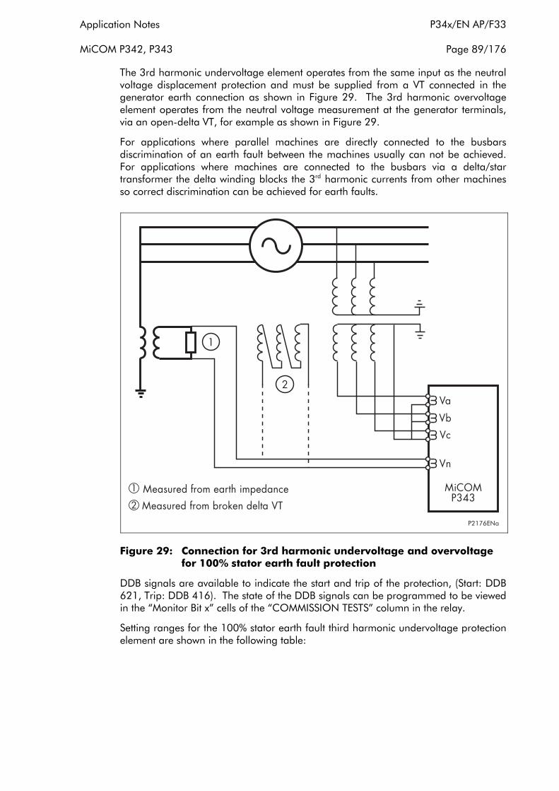
Application Notes P34x/EN AP/F33
MiCOM P342, P343 Page 89/176
The 3rd harmonic undervoltage element operates from the same input as the neutral voltage displacement protection and must be supplied from a VT connected in the generator earth connection as shown in Figure 29. The 3rd harmonic overvoltage element operates from the neutral voltage measurement at the generator terminals, via an open-delta VT, for example as shown in Figure 29.
For applications where parallel machines are directly connected to the busbars discrimination of an earth fault between the machines usually can not be achieved. For applications where machines are connected to the busbars via a delta/star transformer the delta winding blocks the 3rd harmonic currents from other machines so correct discrimination can be achieved for earth faults.
Figure 29: Connection for 3rd harmonic undervoltage and overvoltage for 100% stator earth fault protection
DDB signals are available to indicate the start and trip of the protection, (Start: DDB 621, Trip: DDB 416). The state of the DDB signals can be programmed to be viewed in the “Monitor Bit x” cells of the “COMMISSION TESTS” column in the relay.
Setting ranges for the 100% stator earth fault third harmonic undervoltage protection element are shown in the following table:

P34x/EN AP/F33 Application Notes
Page 90/176 MiCOM P342, P343
Menu Text Default Setting Setting Range
Step Size Min Max
Group 1: 100% EF
100% St EF Status Enabled Disabled, VN3H< Enabled,
VN3H> Enabled
100% St EF VN3H<
1V (Vn=100/120V)
4V (Vn=380/480V)
0.3V (Vn=100/120V)
1.2V (Vn=380/480V)
20V (Vn=100/120V)
80V (Vn=380/480V)
0.1V (Vn=100/120V)
0.4V (Vn=380/480V)
VN3H< Delay 5 s 0 s 100 s 0.01 s
V<Inhibit set
80V (Vn=100/120V)
320V (Vn=380/480V)
30V (Vn=100/120V)
120V (Vn=380/480V)
120V (Vn=100/120V)
480V (Vn=380/480V)
1V (Vn=100/120V)
4V (Vn=380/480V)
P<Inhibit Disabled Enabled, Disabled
P<Inhibit set
4 x Ιn W (Vn=100/120V)
16 x Ιn W (Vn=380/480V)
4 x Ιn W (Vn=100/120V)
16 x Ιn W (Vn=380/480V)
200 x Ιn W (Vn=100/120V)
800 x Ιn W (Vn=380/480V)
0.5 x Ιn W (Vn=100/120V)
2 x Ιn W (Vn=380/480V)
Q<Inhibit Disabled Enabled, Disabled
Q<Inhibit set
4 x Ιn W (Vn=100/120V)
16 x Ιn W (Vn=380/480V)
4 x Ιn W (Vn=100/120V)
16 x Ιn W (Vn=380/480V)
200 x Ιn W (Vn=100/120V)
800 x Ιn W (Vn=380/480V)
0.5 x Ιn W (Vn=100/120V)
2 x Ιn W (Vn=380/480V)
S<Inhibit Disabled Enabled, Disabled
S<Inhibit set
4 x Ιn W (Vn=100/120V)
16 x Ιn W (Vn=380/480V)
4 x Ιn W (Vn=100/120V)
16 x Ιn W (Vn=380/480V)
200 x Ιn W (Vn=100/120V)
800 x Ιn W (Vn=380/480V)
0.5 x Ιn W (Vn=100/120V)
2 x Ιn W (Vn=380/480V)
100% St EF VN3H>
1V (Vn=100/120V)
4V (Vn=380/480V)
0.3V (Vn=100/120V)
1.2V (Vn=380/480V)
20V (Vn=100/120V)
80V (Vn=380/480V)
0.1V (Vn=100/120V)
0.4V (Vn=380/480V)
VN3H> Delay 5 s 0 s 100 s 0.01 s
2.17.1 Setting guidelines for 100% stator earth fault protection
The 100% stator earth fault protection element can be selected by setting the “100% St EF Status” cell to ‘Enabled’.
The third harmonic undervoltage threshold, “100% St EF VN3H<”, must be set below the level of third harmonic voltage present under normal conditions. This voltage can be determined by viewing the “VN 3rd Harmonic” cell in the “MEASUREMENTS 3” menu. A typical value for this threshold could be 0.5V.
The third harmonic overrvoltage threshold, “100% St EF VN3H>”, must be set above the level of third harmonic voltage present under normal conditions. This voltage can be determined by viewing the “VN 3rd Harmonic” cell in the “MEASUREMENTS 3” menu. A typical value for this threshold could be 1V.
A time delay for these elements can be set in the “VN3H< Delay and VN3H> Delay” cells.
Application Notes P34x/EN AP/F33
MiCOM P342, P343 Page 91/176
The terminal voltage interlock threshold, used to prevent operation of the element when the machine is not running, “100% St EF V<Inh”, should typically be set to 80% of machine rated voltage.
The power interlock thresholds, used to prevent operation of the element until there is sufficient load current, “P<Inhibit set, Q<Inhibit set, S<Inhibit”, should be enabled if required to prevent operation under no load conditions. One or more of the thresholds can be used as an interlock. They should be set during commissioning by increasing the load current until the 3rd harmonic undervoltage element is reset and setting the power thresholds above the measured power values. The power values can be determined by viewing the “3 phase Watts, 3 phase VArs, 3 phase VA” cells in the “MEASUREMENTS 2” menu.
Note: Other earth fault protection (residual overvoltage or current operated stator earth fault protection) must also be enabled to provide coverage for earth faults across the complete stator winding.
2.18 Overfluxing protection
Overfluxing or overexcitation of a generator, or transformer connected to the terminals of a generator, can occur if the ratio of voltage to frequency exceeds certain limits. High voltage or low frequency, causing a rise in the V/Hz ratio, will produce high flux densities in the magnetic core of the machine or transformer. This could cause the core of the generator or transformer to saturate and stray flux to be induced in un-laminated components that have not been designed to carry flux. The resulting eddy currents in solid components (e.g. core bolts and clamps) and end of core laminations can cause rapid overheating and damage.
Overfluxing is most likely to occur during machine start up or shut down whilst the generator is not connected to the system. Failures in the automatic control of the excitation system, or errors in the manual control of the machine field circuit, could allow excessive voltage to be generated. It is also possible for overfluxing to occur during parallel operation when the generator has been synchronised with the local supply network. Sudden loss of load could cause an overvoltage condition, in such circumstances, if the generator excitation system does not respond correctly.
The P342/343 relays provide a two stage overfluxing element. The element measures the ratio of voltage, (VAB), to frequency, V/Hz, and will operate when this ratio exceeds the setting. One stage can be set to operate with a definite time or inverse time delay, this stage can be used to provide the protection trip output. The other stage has a definite time delay characteristic and can be used as an alarm stage to indicate unhealthy conditions before damage has occurred to the machine.
DDB signals are also available to indicate the start and trip of the protection, (Start: DDB 636, Trip: DDB 429). A further DDB ‘V/Hz Alarm’ signal is generated from the overfluxing alarm stage (DDB 308). The state of the DDB signals can be programmed to be viewed in the “Monitor Bit x” cells of the “COMMISSION TESTS” column in the relay.
Setting ranges for the Overfluxing protection element are shown in the following table:
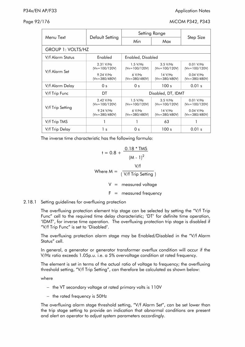
P34x/EN AP/F33 Application Notes
Page 92/176 MiCOM P342, P343
Menu Text Default Setting Setting Range
Step Size Min Max
GROUP 1: VOLTS/HZ
V/f Alarm Status Enabled Enabled, Disabled
V/f Alarm Set
2.31 V/Hz (Vn=100/120V)
9.24 V/Hz (Vn=380/480V)
1.5 V/Hz (Vn=100/120V)
6 V/Hz (Vn=380/480V)
3.5 V/Hz (Vn=100/120V)
14 V/Hz (Vn=380/480V)
0.01 V/Hz (Vn=100/120V)
0.04 V/Hz (Vn=380/480V)
V/f Alarm Delay 0 s 0 s 100 s 0.01 s
V/f Trip Func DT Disabled, DT, IDMT
V/f Trip Setting
2.42 V/Hz (Vn=100/120V)
9.24 V/Hz (Vn=380/480V)
1.5 V/Hz (Vn=100/120V)
6 V/Hz (Vn=380/480V)
3.5 V/Hz (Vn=100/120V)
14 V/Hz (Vn=380/480V)
0.01 V/Hz (Vn=100/120V)
0.04 V/Hz (Vn=380/480V)
V/f Trip TMS 1 1 63 1
V/f Trip Delay 1 s 0 s 100 s 0.01 s
The inverse time characteristic has the following formula:
0.18 * TMSt = 0.8 +
(M - 1)2
V/fWhere M = ( V/f Trip Setting )
V = measured voltage
F = measured frequency
2.18.1 Setting guidelines for overfluxing protection
The overfluxing protection element trip stage can be selected by setting the “V/f Trip Func” cell to the required time delay characteristic; ‘DT’ for definite time operation, ‘IDMT’, for inverse time operation. The overfluxing protection trip stage is disabled if “V/f Trip Func” is set to ‘Disabled’.
The overfluxing protection alarm stage may be Enabled/Disabled in the “V/f Alarm Status” cell.
In general, a generator or generator transformer overflux condition will occur if the V/Hz ratio exceeds 1.05p.u. i.e. a 5% overvoltage condition at rated frequency.
The element is set in terms of the actual ratio of voltage to frequency; the overfluxing threshold setting, “V/f Trip Setting”, can therefore be calculated as shown below:
where
− the VT secondary voltage at rated primary volts is 110V
− the rated frequency is 50Hz
The overfluxing alarm stage threshold setting, “V/f Alarm Set”, can be set lower than the trip stage setting to provide an indication that abnormal conditions are present and alert an operator to adjust system parameters accordingly.

Application Notes P34x/EN AP/F33
MiCOM P342, P343 Page 93/176
The time delay settings should be chosen to match the withstand characteristics of the protected generator or generator/transformer. If an inverse time characteristic is selected, the time multiplier setting, “V/f Trip TMS”, should be chosen so the operating characteristic closely matches the withstand characteristic of the generator or generator/transformer. If a definite time setting is chosen for the trip stage the time delay is set in the “V/f Trip Delay” cell. The alarm stage time delay is set in the “V/f Alarm Delay” cell.
Reference should be made to manufacturers withstand characteristics before formulating these settings.
2.19 Dead machine/unintentional energisation at standstill protection
Accidental energisation of a generator when the machine is not running can cause severe damage to the machine. If the breaker is closed, when the machine is at standstill, the generator will begin to act as an induction motor with the surface of the rotor core and the rotor winding slot wedges acting as the rotor current conductors. This abnormal current in the rotor can cause arcing between components, e.g. slot wedge to core, and results in rapid overheating and damage.
To provide fast protection for this condition, the P343 relay provides an instantaneous overcurrent element that is gated with a three phase undervoltage detector. The scheme logic of this function is shown in Figure 30.
The element is enabled when the machine is not running, i.e. not generating any voltage, or when the breaker is open. Therefore the element can have a low current setting, resulting in high speed operation when required. For the element to operate correctly the relay voltage input must be from a machine side VT; busbar VTs cannot be used.
Figure 30: Fixed scheme logic for unintentional energisation of standstill protection
Setting ranges for the Dead Machine/Unintentional Energisation protection element are shown in the following table:
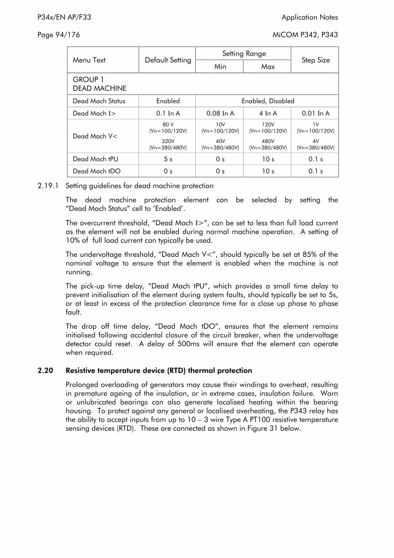
P34x/EN AP/F33 Application Notes
Page 94/176 MiCOM P342, P343
Menu Text Default Setting Setting Range
Step Size Min Max
GROUP 1 DEAD MACHINE
Dead Mach Status Enabled Enabled, Disabled
Dead Mach Ι> 0.1 Ιn A 0.08 Ιn A 4 Ιn A 0.01 Ιn A
Dead Mach V<
80 V (Vn=100/120V)
320V (Vn=380/480V)
10V (Vn=100/120V)
40V (Vn=380/480V)
120V (Vn=100/120V)
480V (Vn=380/480V)
1V (Vn=100/120V)
4V (Vn=380/480V)
Dead Mach tPU 5 s 0 s 10 s 0.1 s
Dead Mach tDO 0 s 0 s 10 s 0.1 s
2.19.1 Setting guidelines for dead machine protection
The dead machine protection element can be selected by setting the “Dead Mach Status” cell to ‘Enabled’.
The overcurrent threshold, “Dead Mach Ι>”, can be set to less than full load current as the element will not be enabled during normal machine operation. A setting of 10% of full load current can typically be used.
The undervoltage threshold, “Dead Mach V<”, should typically be set at 85% of the nominal voltage to ensure that the element is enabled when the machine is not running.
The pick-up time delay, “Dead Mach tPU”, which provides a small time delay to prevent initialisation of the element during system faults, should typically be set to 5s, or at least in excess of the protection clearance time for a close up phase to phase fault.
The drop off time delay, “Dead Mach tDO”, ensures that the element remains initialised following accidental closure of the circuit breaker, when the undervoltage detector could reset. A delay of 500ms will ensure that the element can operate when required.
2.20 Resistive temperature device (RTD) thermal protection
Prolonged overloading of generators may cause their windings to overheat, resulting in premature ageing of the insulation, or in extreme cases, insulation failure. Worn or unlubricated bearings can also generate localised heating within the bearing housing. To protect against any general or localised overheating, the P343 relay has the ability to accept inputs from up to 10 – 3 wire Type A PT100 resistive temperature sensing devices (RTD). These are connected as shown in Figure 31 below.

Application Notes P34x/EN AP/F33
MiCOM P342, P343 Page 95/176
Figure 31: Connection for RTD thermal probes
Such probes can be strategically placed in areas of the machine which are susceptible to overheating or heat damage. Where power transformers are located close to the protected machine, certain RTD probes could be assigned to provide overtemperature protection for the transformer(s). This could protect against winding hot spot overheating or overtemperature in the bulk of the insulating oil.
Typically a PT100 RTD probe can measure temperature within the range –40° to +300°C. The resistance of these devices changes with temperature, at 0°C they have a resistance of 100Ω. The temperature at each probe location can be determined by the relay, and is available for:
• Temperature monitoring, displayed locally, or remotely via the relay communications.
• Alarming, should a temperature threshold be exceeded for longer than a set time delay.
• Tripping, should a temperature threshold be exceeded for longer than a set time delay.
Should the measured resistance be outside of the permitted range, an RTD failure alarm will be raised, indicating an open or short circuit RTD input. These conditions are signalled via DDB signals available within the PSL (DDB 310-314) and are also shown in the measurements 3 menu.
DDB signals are also available to indicate the alarm and trip of the each RTD, (Alarm: DDB 743-752 Trip: DDB 430-439). The state of the DDB signals can be programmed to be viewed in the “Monitor Bit x” cells of the “COMMISSION TESTS” column in the relay.
Note that direct temperature measurement can provide more reliable thermal protection than devices which use a thermal replica energised from phase current. The latter is susceptible to inaccuracies in time constants used by the replica model, and also inaccuracies due to the variation in ambient temperature.

P34x/EN AP/F33 Application Notes
Page 96/176 MiCOM P342, P343
See the Installation section (P34x/EN IN) of the Operating Guide, for recommendations on RTD connections and cables.
Setting ranges for the RTD Thermal protection are shown in the following table:
Menu Text Default Setting Setting Range
Step Size Min Max
GROUP 1 RTD PROTECTION
Select RTD 0000000000
Bit 0 - Select RTD 1 Bit 1 - Select RTD 2 Bit 2 - Select RTD 3 Bit 3 - Select RTD 4 Bit 4 - Select RTD 5 Bit 5 - Select RTD 6 Bit 6 - Select RTD 7 Bit 7 - Select RTD 8 Bit 8 - Select RTD 9 Bit 9 - Select RTD 10
RTD x Alarm Set 80°C 0°C 200°C 1°C
RTD x Alarm Dly 10s 0 100s 1s
RTD x Trip Set 85°C 0°C 200°C 1°C
RTD x Trip Dly 1s 0 100s 1s
Where x = 1 to 10
2.20.1 Setting guidelines for RTD thermal protection
Each RTD can be enabled by setting the relevant bit in “Select RTD”. For example if Select RTD is set to 0000000111, then RTD1, RTD2 and RTD3 would be enabled and the associated settings would be visible in the menu.
The temperature setting for the alarm stage for each RTD can be set in the “RTD x Alarm Set” cells and the alarm time delay in the “RTD x Alarm Dly” cell.
The temperature setting for the trip stage for each RTD can be set in the “RTD x Trip Set” cells and the trip stage time delay in the “RTD x Trip Dly” cell.
Typical operating temperatures for protected plant are given in the table below. These are provided as a guide, actual figures MUST be obtained from the equipment manufacturers:
Parameter Typical Service Temperature Short Term Overloading at Full Load
Bearing temperature generators
60 – 80°C, depending on the type of bearing. 60 – 80°C+
Top oil temperature of transformers
80°C (50 – 60°C above ambient).
A temperature gradient from winding temperature is usually assumed, such that top oil RTDs can provide winding protection.

Application Notes P34x/EN AP/F33
MiCOM P342, P343 Page 97/176
Parameter Typical Service Temperature Short Term Overloading at Full Load
Winding hot spot temperature
98°C for normal ageing of insulation. Cyclic overloading might give
140°C+ during emergencies
Table showing typical operating temperatures of plant.
2.21 P342 pole slipping protection
A generator might pole slip, or fall out-of-step with other power system sources, in the event of failed or abnormally weak excitation or as a result of delayed system fault clearance. This can be further aggravated when there is a weak (high reactance) transmission link between the generator and the rest of the power system.
The process of pole slipping following excitation failure is discussed in section 2.10. The P342 field failure protection function should respond to such situations to give a time delayed trip. The electrical/mechanical power/torque oscillations following excitation failure may be relatively gentle. If pole slipping occurs with maximum excitation (generator emf >2.0 p.u.), the power/torque oscillations and power system voltage fluctuations following loss of stability can be much more severe. For large machines there may be a requirement to provide protection to trip the generator under such circumstances, to prevent plant damage or remove the disturbance to the power system.
Pole slipping protection is frequently requested for relatively small generators running in parallel with strong public supplies. This might be where a co-generator runs in parallel with the distribution system of a public utility, which may be a relatively strong source, but where high-speed protection for distribution system faults is not provided. The delayed clearance of system faults may pose a stability threat for the co-generation plant.
With the P342 relay there is no specific pole slipping protection function, but a number of the protection functions provided can offer a method of ensuring delayed tripping, if appropriately applied.
2.21.1 Reverse power protection
During a pole slipping event the machine will cyclically absorb and export power as the machine rotor slips with respect to the power system. Therefore, any power element selected to operate from reverse power can pick-up during the pole slip. Reverse power protection tripping is usually time delayed and this time delay will prevent the element from tripping during a pole slip. However, each power protection stage in the P342 relay has an associated delay on drop off, or reset, timer (“Power1 DO Timer”, “Power2 DO Timer”). This can be used to prevent resetting of the reverse power stage during a pole slipping event, leading to eventual tripping if the event continues.
2.21.2 System back-up protection function
In a similar manner to the power protection function, the system back-up protection function would operate cyclically with the periodic high levels of stator current that would arise during pole slipping. These peaks of current may also be accompanied by coincident drops in generator terminal voltage, if the generator is near the electrical centre of swinging. As discussed in section 2.5, the system back-up protection function is provided with a timer characteristic timer-hold setting, “V Dep OC tRESET”, “Z< tRESET”, which can be used to ensure that the protection function will respond to cyclic operation during pole slipping. In a similar manner, some
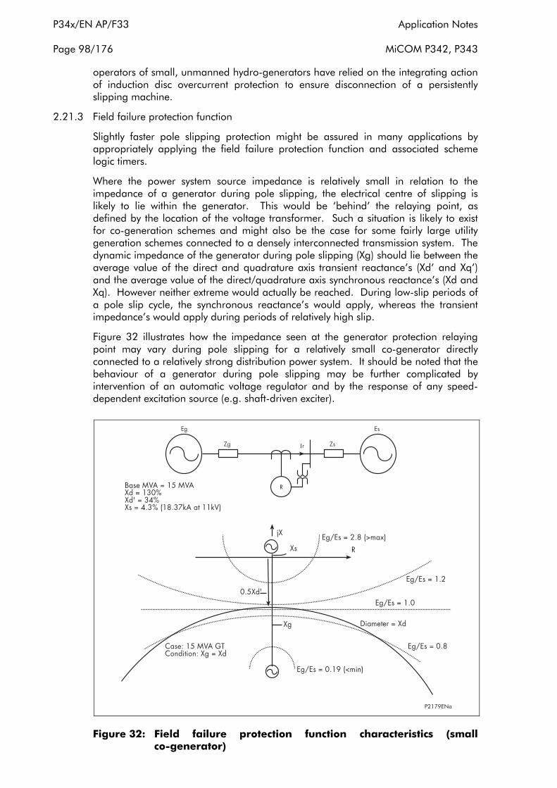
P34x/EN AP/F33 Application Notes
Page 98/176 MiCOM P342, P343
operators of small, unmanned hydro-generators have relied on the integrating action of induction disc overcurrent protection to ensure disconnection of a persistently slipping machine.
2.21.3 Field failure protection function
Slightly faster pole slipping protection might be assured in many applications by appropriately applying the field failure protection function and associated scheme logic timers.
Where the power system source impedance is relatively small in relation to the impedance of a generator during pole slipping, the electrical centre of slipping is likely to lie within the generator. This would be ‘behind’ the relaying point, as defined by the location of the voltage transformer. Such a situation is likely to exist for co-generation schemes and might also be the case for some fairly large utility generation schemes connected to a densely interconnected transmission system. The dynamic impedance of the generator during pole slipping (Xg) should lie between the average value of the direct and quadrature axis transient reactance’s (Xd’ and Xq’) and the average value of the direct/quadrature axis synchronous reactance’s (Xd and Xq). However neither extreme would actually be reached. During low-slip periods of a pole slip cycle, the synchronous reactance’s would apply, whereas the transient impedance’s would apply during periods of relatively high slip.
Figure 32 illustrates how the impedance seen at the generator protection relaying point may vary during pole slipping for a relatively small co-generator directly connected to a relatively strong distribution power system. It should be noted that the behaviour of a generator during pole slipping may be further complicated by intervention of an automatic voltage regulator and by the response of any speed-dependent excitation source (e.g. shaft-driven exciter).
Figure 32: Field failure protection function characteristics (small co-generator)

Application Notes P34x/EN AP/F33
MiCOM P342, P343 Page 99/176
It can be seen from the simple analysis of Figure 32 that the field failure protection function may respond to the variation in impedance seen during pole slipping for some applications. However the impedance characteristic offset might have to be reduced to guarantee response for the theoretical lower range of dynamic generator impedance (Xg). The lack of the normally recommended characteristic offset should not pose any problem of unwanted protection function response during the normal range of operation of a machine (with rotor angles kept below 90°), but a longer trip time delay might be required to prevent unwanted protection response during stable power swings caused by system disturbances. The most marginal condition to detect is where the generator is fully loaded, with maximum excitation applied. Even if the impedance characteristic offset is not reduced, impedance element pick up should still occur during part of a slip cycle, when the machine impedance is high and where the rotor angle is high. More careful consideration might have to be given to the reset time delay setting (“FFail1 DO Timer”) required in such circumstances.
During pole slipping, any operation of the field failure protection function will be cyclic and so it would be necessary to set the reset time delay (“FFail1 DO Timer”) to be longer than the time for which the impedance seen will cyclically lie outside the field failure characteristic. A typical delay setting might be 0.6s, to cover slip frequencies in excess of 2Hz. When the timer “FFail1 DO Timer” is set, the field failure trip time delay (“FFail1 Time Delay”) must be increased to be greater than the setting of “FFail1 DO Timer”.
Sometimes pole slipping protection must be guaranteed, especially in the case of a larger utility generator connected to a relatively weak transmission system. In such applications, and where fast tripping is required, or where the pole slipping response of field failure protection function is otherwise uncertain, a stand-alone protection scheme, such as used in the P343 should be used. The delayed detection and tripping offered by the P340 Field Failure protection function should, however, be adequate for many applications.
For further details regarding setting of field failure protection for time delayed pole slipping detection, contact AREVA T&D.
2.22 P343 pole slipping protection
2.22.1 Introduction
Sudden changes or shocks in an electrical power system such as line switching operations, large jumps in load or faults may lead to power system oscillations which appear as regular variations of the currents, voltages and angular separation between systems. This phenomenon is referred to as a power swing.
In a recoverable situation, the power swing will decay and finally disappear in a few seconds. Synchronism will be regained and the power system will recover to stable operation. In a non-recoverable situation, the power swing becomes so severe that synchronism is lost between the generator and system, a condition recognised as out-of-step or pole slipping from the view of a generator. If such a loss of synchronism does occur, it is imperative to separate the asynchronous areas from the rest of the system before generators are damaged or before a widespread outage can occur.
Pole slipping occurs when the prime mover input power of a generator exceeds the electrical power absorbed by the system. The condition results from the mismatch in the operating frequencies of two or more machines. During pole slipping the machine produces alternatively generating and motoring torque of high magnitudes with corresponding current peaks and voltage dips.

P34x/EN AP/F33 Application Notes
Page 100/176 MiCOM P342, P343
During normal system operation the following events can lead to the generator pole slipping condition.
• The occurrence of an abnormality such as:
A transient system fault.
The failure of the generator governor.
The failure of the generator excitation control (asynchronous running).
Reconnection of an 'islanded' system without synchronisation.
• The transient change in the system requirements of real and reactive power components sets the generator rotor to oscillate around the new equilibrium point.
• If the initial transient disturbance is severe enough and for a sufficiently long duration the rotor swing may exceed the maximum stability limit causing the generator to slip poles.
• For a weak system switching transients may also result in pole slipping.
Nowadays, with the advent of EHV systems, large conductor-cooled generators and with the expansion of the transmission system, system and generator impedances have changed considerably. System impedances have decreased while generator and step-up transformer impedances have increased. This trend has resulted in the impedance centre during a power swing appearing inside the step-up transformer or inside the generator, which is generally out of the protection zone of conventional out-of-step relays installed in the system. Therefore, separate relaying should be applied to protect the machine against pole slipping.
Relays employing impedance-measuring elements for the detection of the pole slipping condition utilise the generator terminal voltage and current signals as inputs. During a generator pole slip the system voltage and current go through slip frequency variations of extremely high amplitude. These variations are reflective of the corresponding apparent changes in the generator terminal impedance. The relay will be able to detect the condition only after the generator has actually slipped poles. The conventional technique employs measurement of generator terminal impedance to determine pole slipping conditions. Directional and blinder elements are used together with a mho element to obtain the desired relay characteristics.
2.22.2 Loss of synchronism characteristics
Before any further discussion, it is necessary to have a brief review of the loss of synchronism characteristic which is used in the analysis of generator pole slipping.
A common method used to detect a loss of synchronism is to analyse the apparent impedance as measured at the generator terminals. According to the simplified representation of a machine and system shown in Figure 33, the impedance presented to the relay ZR (installed at point A) under a loss of synchronism (recoverable power swing or pole slipping) condition can be described by equation1:
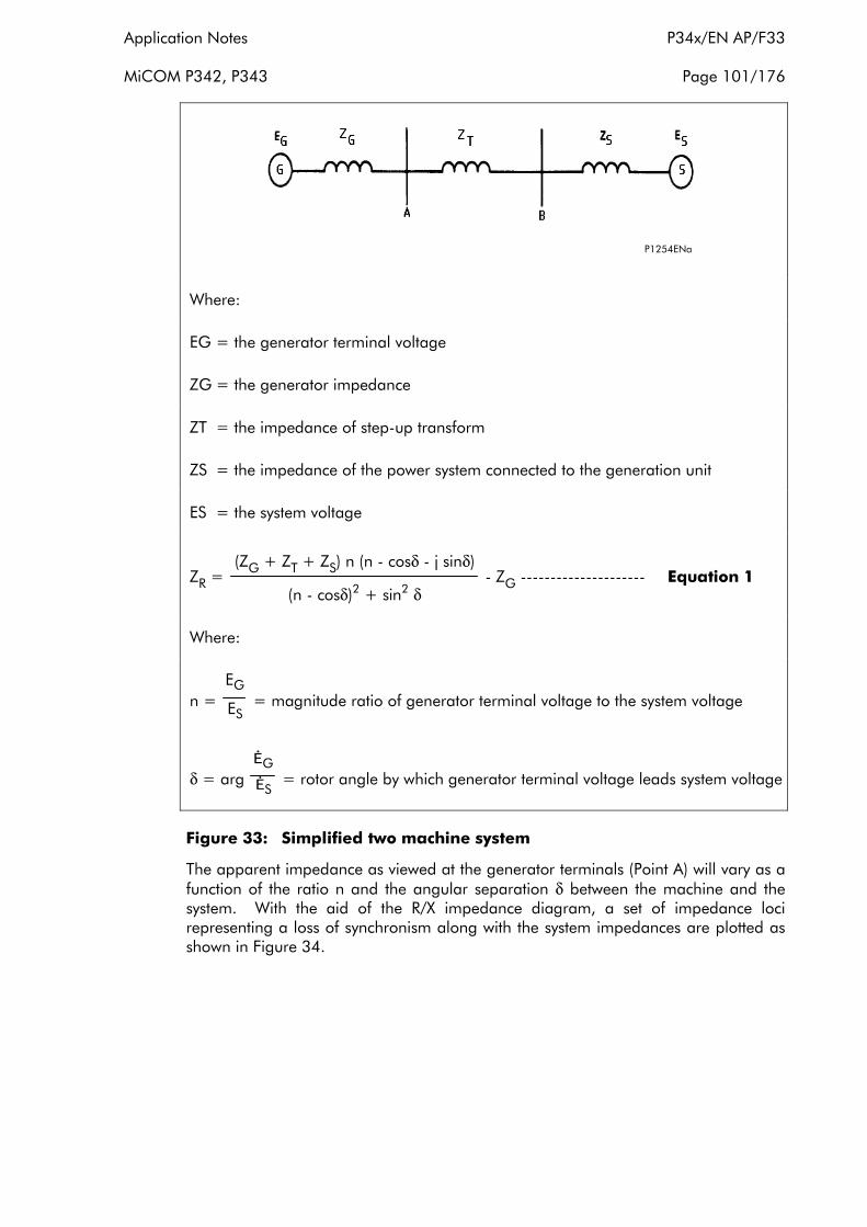
Application Notes P34x/EN AP/F33
MiCOM P342, P343 Page 101/176
P1254ENa
Where:
EG = the generator terminal voltage
ZG = the generator impedance
ZT = the impedance of step-up transform
ZS = the impedance of the power system connected to the generation unit
ES = the system voltage
(ZG + ZT + ZS) n (n - cosδ - j sinδ)ZR = - ZG --------------------- Equation 1
(n - cosδ)2 + sin2 δ
Where:
EG n = = magnitude ratio of generator terminal voltage to the system voltage ES
ĖG δ = arg ĖS
= rotor angle by which generator terminal voltage leads system voltage
Figure 33: Simplified two machine system
The apparent impedance as viewed at the generator terminals (Point A) will vary as a function of the ratio n and the angular separation δ between the machine and the system. With the aid of the R/X impedance diagram, a set of impedance loci representing a loss of synchronism along with the system impedances are plotted as shown in Figure 34.

P34x/EN AP/F33 Application Notes
Page 102/176 MiCOM P342, P343
P1255ENa
Figure 34: Apparent impedance loci viewed at the generator terminal (point A)
It has been well proven that the locus of the impedance as measured at the generator terminals (point A) is either a straight line or circular depending on whether EG and ES are of equal or different magnitudes. The impedance locus is a straight line which is a perpendicular bisector of the total system impedance between G and S when EG / ES = 1. When EG / ES > 1, the circular locus is located above the bisector with its centre on the extension of the total impedance line GS. When EG / ES < 1, the impedance locus is situated below the bisector with its centre on the extension of the total impedance line SG.
The diameters and centres of these circles are a function of the voltage ratio EG / ES and the total impedance, as shown in Figure 34. It is not always necessary to go into the detail of plotting the circular characteristic to identify the loss of synchronism. In most cases, it is only necessary to simply draw the perpendicular bisector to the total impedance line to locate the point on the system where the swing will traverse which is sufficiently accurate for relaying purposes.
It should be noted that the angle formed by the intersection of lines SL and GL on line ML is the angle of separation δ between the generator and system. During an unrecoverable power swing, δ oscillates between 0 and 360 degrees according to the points L and M on the bisector. There are several points of interest along line LM. The first is the point where the separation reaches 90 degrees. If we draw a circle whose diameter is the total impedance, line GS, the intersection of the circle and line LM will be the point where δ=90 degrees. If the swing locus does not go beyond this point the system will be able to regain synchronism. However, if the locus reaches 120 degrees or more, the system is not likely to recover. When the impedance locus intersects the total impedance, line GS, the generator and system are 180 degree out of phase, which is known as the electrical centre or impedance centre of the system.

Application Notes P34x/EN AP/F33
MiCOM P342, P343 Page 103/176
As the locus crosses this point and enters the left hand side of the line GS, the generator and system will become more in phase. A slip cycle has been completed when the locus reaches the point where the swing started.
Note that the following assumptions have been made in this simplified approach:
• EG/ ES is assumed to remain constant during the swing.
• Initial transients and effects of generator saliency are neglected.
• Transient changes in impedance due to a fault or clearance of fault have subsided.
• Effect of regulator and governor are neglected.
2.22.3 Generator pole slipping characteristics
As noted previously, generator and system impedances have changed in the past few decades. In many instances, the electrical centre or impedance centre lies within the generator or step-up transformer. Also, for most machine loadings, the equivalent internal machine voltage will be less than 1.0 per unit and so less than the equivalent system voltage. Therefore, the pole slipping characteristics viewed at the generator terminals will generally follow the loss of synchronism characteristic where the voltage ratio EG/ ES < 1 which is below the impedance centre. See the locus EG/ ES < 1 in Figure 34 for example.
In reality the impedance loci as viewed at the generator terminals may be distorted compared with the ideal loci. The following discussion illustrates the impact on the pole slipping characteristic when other factors are taken into account.
2.22.3.1What happens if EG / ES has different values less than one (1)?
For a given total impedance, as the voltage ratio decreases below one (1), the circle also decreases in diameter and the centre moves closer to the origin. Therefore, a decreased internal voltage results in the impedance loci having a smaller diameter. The radius and circular centre calculations using the equation shown in Figure 34 shows these trends.
During a fault, if the voltage regulator is out of service the internal machine voltage will decay and will remain at the resulting lower level after the fault is cleared. If the effects of the voltage regulator during a fault is included, the impedance locus circles are larger in diameter but will still be in the generator zone.
2.22.3.2What happens if different system impedances are applied?
System impedance also plays a part in the determination of the circle diameter and location. If the system impedance decreases, the locus decreases in diameter and moves closer to the origin.
It should be noted that the impedance centre of the system is not a fixed point due to the variation of system impedance under different operating conditions. Therefore, the impedance loci should be determined at the maximum and minimum systems impedances.
2.22.3.3How to determine the generator reactance during a pole slipping condition?
Since the generator reactance plays a role in the determination of the pole slipping impedance locus, it is crucial to use proper reactance values when we plot these loci. At zero slip XG is equal to the synchronous reactance (Xd), and at 100% slip XG is
equal to sub-transient reactance (X’’d). The impedance in a typical case has been
P34x/EN AP/F33 Application Notes
Page 104/176 MiCOM P342, P343
shown to be equal to the transient reactance X’d at 50% slip, and to 2X’d with a slip of 0.33%. As most slips are likely to be experienced at low asynchronous speed running, perhaps 1%, it is sufficient to take the value XG=2X’d when assessing pole slipping.
2.22.3.4How to determine the slip rate of pole slipping?
The rate of slip between the generator and power system is a function of the accelerating torque and inertia of the systems. In general, the slip rate can not be obtained analytically. It is recommended to determine the slip rate by transient stability studies where the angular excursion of the system is plotted versus time. Although the slip rate will not be constant during a pole slipping condition, it is reasonable to assume a constant for the first half slip cycle which is of interest to the relay. For the tandem generator, it is in the range of 250 to 400 degrees/sec. Whilst for the cross compound units, the average initial slip will be 400 to 800 degrees/sec.
2.22.4 General requirements for pole slipping protection
Having got some ideas about the characteristics of pole slipping, general rules for pole slipping protection could be obtained as listed below:
• On the whole, the pole slipping protection must remain stable under all fault conditions and recoverable power swings other than a genuine non-recoverable pole slipping condition.
• For a particular loss of synchronism condition, if the impedance centre happens to lie in the generator/step-up transformer zone, it is recommended the generator be tripped without delay, preferably during the first half slip cycle of a loss of synchronism condition. If the centre lies outside of the zone, then the pole slipping relay should not trip immediately, but should allow time for tripping to take place at some other location external to the power station. Only if this should fail must the pole slipping protection respond in stage II, i.e. after a pre-set number of slips, to isolate the generator.
• In order to reduce the damage to the generator during a pole slip, it must reliably detect the first and subsequent slips of a synchronous machine within a wide range (slipping frequency 0.1% to 10% of fn).
• The tripping should avoid the point where the generator and the system are 180 degrees out-of-phase, when the currents reach the maximum value and subject the circuit breaker to a maximum recovery voltage during interruption.
• Since pole slipping is essentially a balanced three-phase phenomenon, only a single phase element need be implemented in the protection relay.
2.22.5 Lenticular scheme
2.22.5.1Characteristic
The P343 pole slipping characteristic consists of three parts as shown in the R/X diagram of Figure 35. The first part is the lenticular (lens) characteristic. The second is a straight line referred to as the blinder that bisects the lens and divides the impedance plane into the left and right halves. The third is a reactance line which is perpendicular to the blinder.
The inclination of the lens and the blinder, θ, is determined by the angle of the total system impedance. The equivalent impedance of the system and the step-up transformer determines the forward reach of the lens, ZA, whereas the generator’s transient reactance determines the reverse reach ZB. The width of the lens is varied

Application Notes P34x/EN AP/F33
MiCOM P342, P343 Page 105/176
by the setting of the angle α. A reactance line, perpendicular to the axis of the lens, is used to distinguish whether the impedance centre of the swing is located in the power system or in the generator. It is set by the value of Zc along the axis of the lens, as shown in Figure 35. The reactance line splits the lens into Zone 1 (below the line) and Zone 2 (above the line).
For the pole slipping protection element the minimum operating current is 2% Ιn and the minimum voltage is 1 V for 100/120 and 4V for 380/480 V ratings. The pole slipping protection operates from the ΙA and VA current and voltage inputs to the relay.
Blinder
Reactance Line
R
Lens
ZA
ZB
X
θ α
ZC
P1256ENa
Figure 35: Pole slipping protection using blinder and lenticular characteristic
2.22.5.2Generating and motoring modes
When a generator is out of step with the system, the impedance locus is expected to traverse from right to left across the lens and the blinder. However, if the generator is running as a motor, as in the pumping mode of a pump storage generator, the impedance locus is expected to swing from the left to the right. A setting is provided to determine whether the protection operates in a generating mode or in a motoring mode or both.
If the protection is running in the generating mode, the impedance is expected to be at the right hand side of the lens under normal load conditions. During a pole slip the impedance locus traverses across the right half and the left half of the lens. The minimum time spent in each half of the lens can be set with timers T1 for the right hand side and T2 for the left hand side. The relay registers a pole slipping cycle when the locus finally leaves the lens at the opposite end.
If the protection is running in the motoring mode, the impedance is expected to be at the left hand side of the lens under normal load conditions. During a pole slip the impedance locus traverses across the left half and the right half of the lens, again spending at least the time T1 and T2 respectively in each half and leaves the lens at the opposite end.

P34x/EN AP/F33 Application Notes
Page 106/176 MiCOM P342, P343
2.22.6 Pole slipping protection operation
The pole slipping protection algorithm is executed 4 times per power system cycle to obtain accurate timing of the impedance locus traversing the lens.
2.22.6.1State machine
Figure 36: State machine
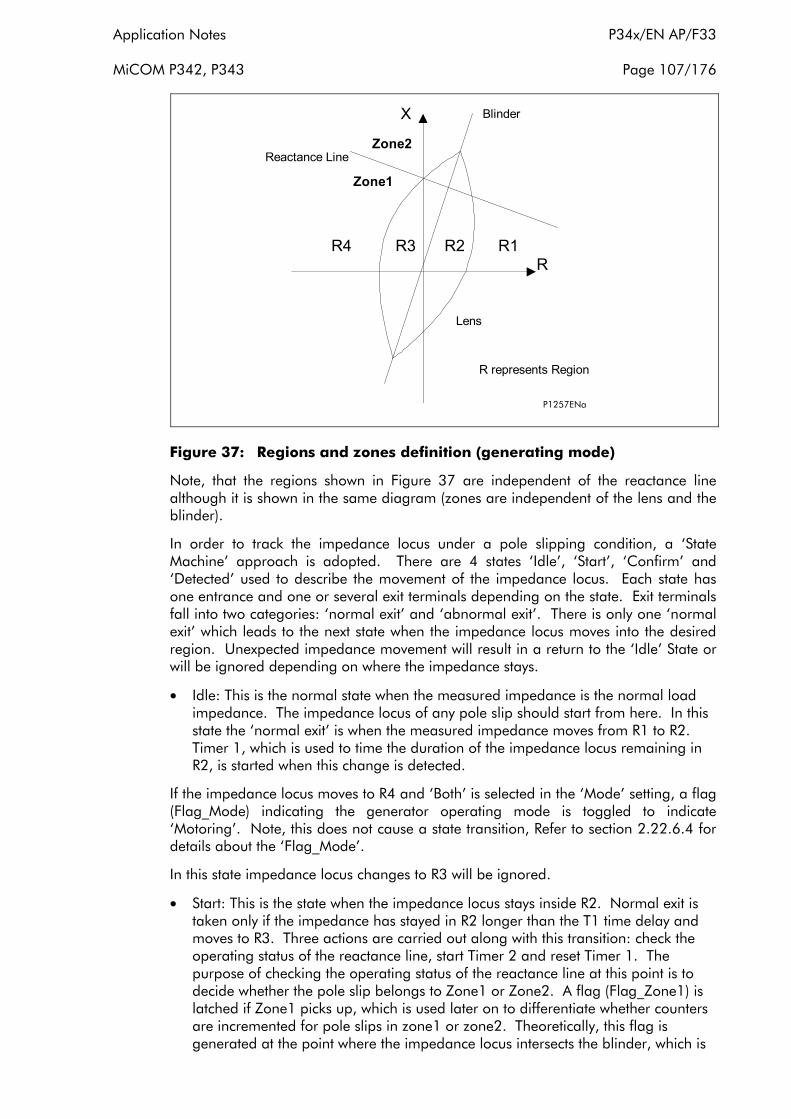
Application Notes P34x/EN AP/F33
MiCOM P342, P343 Page 107/176
R1
Reactance Line
R
X
R2R3R4
R represents Region
Zone2
Zone1
Blinder
Lens
P1257ENa
Figure 37: Regions and zones definition (generating mode)
Note, that the regions shown in Figure 37 are independent of the reactance line although it is shown in the same diagram (zones are independent of the lens and the blinder).
In order to track the impedance locus under a pole slipping condition, a ‘State Machine’ approach is adopted. There are 4 states ‘Idle’, ‘Start’, ‘Confirm’ and ‘Detected’ used to describe the movement of the impedance locus. Each state has one entrance and one or several exit terminals depending on the state. Exit terminals fall into two categories: ‘normal exit’ and ‘abnormal exit’. There is only one ‘normal exit’ which leads to the next state when the impedance locus moves into the desired region. Unexpected impedance movement will result in a return to the ‘Idle’ State or will be ignored depending on where the impedance stays.
• Idle: This is the normal state when the measured impedance is the normal load impedance. The impedance locus of any pole slip should start from here. In this state the ‘normal exit’ is when the measured impedance moves from R1 to R2. Timer 1, which is used to time the duration of the impedance locus remaining in R2, is started when this change is detected.
If the impedance locus moves to R4 and ‘Both’ is selected in the ‘Mode’ setting, a flag (Flag_Mode) indicating the generator operating mode is toggled to indicate ‘Motoring’. Note, this does not cause a state transition, Refer to section 2.22.6.4 for details about the ‘Flag_Mode’.
In this state impedance locus changes to R3 will be ignored.
• Start: This is the state when the impedance locus stays inside R2. Normal exit is taken only if the impedance has stayed in R2 longer than the T1 time delay and moves to R3. Three actions are carried out along with this transition: check the operating status of the reactance line, start Timer 2 and reset Timer 1. The purpose of checking the operating status of the reactance line at this point is to decide whether the pole slip belongs to Zone1 or Zone2. A flag (Flag_Zone1) is latched if Zone1 picks up, which is used later on to differentiate whether counters are incremented for pole slips in zone1 or zone2. Theoretically, this flag is generated at the point where the impedance locus intersects the blinder, which is

P34x/EN AP/F33 Application Notes
Page 108/176 MiCOM P342, P343
called the electrical centre. Timer2 is used to time the duration of the impedance locus remaining in R3;
If the impedance moves to R1 or R4 or moves to R3 but stays in R2 less than T1, the state machine will be reset to the ‘Idle’ state. Timer 1 is reset when the impedance leaves R2 via these abnormal exits. Besides pole slipping, a stable power swing or fault occurrence could enter this state as well. The state machine is designed to differentiate these conditions.
• Confirm: This state is reached when the impedance has crossed the blinder and arrived at Region3. Further confirmation is required to see if the impedance stays for at least time T2 and is bound to leave for R4. Otherwise, an abnormal exit will reset the state machine to the ‘Idle’ state. Actions on abnormal transition include resetting Flag_Zone1 and Timer 2. Note, that as soon as the impedance locus leaves the lens through the normal exit counters of different zones will be updated, depending on the Flag_Zone1 and if the pole slip has completed the pre-set slip cycles setting a trip signal is given. If Flag_Zone1 is set then the Zone 1 counter (C1) will be incremented. Zone 2 is the backup pole slipping stage and so all pole slips increment the Zone2 counter (C2).
The Reset_Timer and reset Timer 2 are started when the normal transition occurs. The Reset_Timer is started only when the first pole slip is detected and will be reset in its time delay (see Reset_Timer time out actions in the state machine diagram).
• Detected: This is the stage where the impedance locus has to complete it’s full cycle although the counter is updated in the previous confirm stage. Abnormal movements of the impedance locus in this stage will be ignored and this state is kept until the impedance moves to R1 indicating completion of a pole slip cycle. If a trip signal has not been given for this pole slip, only the Start_Signals and Flag_Zone1 are reset in preparation for the next pole slip cycle. However, if a trip signal has been issued, then the Trip_Signals and the counters are both reset.
In general, once the measured impedance has traversed all the ‘States’ in the normal exit sequence, a pole slip is confirmed. For a stable power swing or fault condition the measured impedance will not satisfy all the exit transition criteria.
The ‘State Machine’ diagram has been simplified to present an overview of how to detect pole slipping. There are also several supporting protection functions which are explained in the following sections.

Application Notes P34x/EN AP/F33
MiCOM P342, P343 Page 109/176
2.22.6.2Protection functions and logic structure
poleslz_Zone1Pu( )
&
&
&
&
poleslz_BlinderPu() (Generating Mode - Pick-up zone left of blinder; Motoring Mode - Pick-up zone right of blinder)
poleslz_LensPu()
R1
R2
R3
R4
Pole Slipping State Machine
Genuine Pole Slipping
& Zone1 Count++
Zone2 Count++
Zone 1 Trip
Zone 2 Trip
IAi,IAj
VAi, VAj
poleslz_RegionCal
Zone1 Start
Zone2 Start
Flag_Zone1
P1258ENa
Figure 38: Logic structure of pole slipping module
There are several protection functions called in sequence in the pole slipping detection, as shown in the above diagram, they are
• poleslz_Zone1Pu
• poleslz_LensPu
• poleslz_BlinderPu
• poleslz_RegionCal
Function poleslz_Zone1Pu(), poleslz_LensPu() and Poleslz_BlinderPu() calculate whether the Reactance Line, Lens and Blinder characteristics have picked up respectively. At the end of each function, DDBs associated with each characteristic are mapped according to the elements operating status. Outputs from poleslz_LensPu() and Poleslz_BlinderPu() feed into the poleslz_RegionCal() to determine in which ‘Region’ the locus is present. After the region and zone have been determined the state machine can be evaluated.
For the purpose of discriminating the pole slipping zone, Zone1 or Zone2, it is important to check the result of poleslz_Zone1Pu() when the impedance locus leaves the ‘Start’ state by the ‘normal exit’. A flag is latched if Zone1 picks up, which is used to identify the pole slipping zone later on.

P34x/EN AP/F33 Application Notes
Page 110/176 MiCOM P342, P343
2.22.6.3Motoring mode
When the ‘pole slip mode’ setting is set to ‘motoring’ the protection algorithm is switched to motoring mode. Motoring mode is essentially the same for generating mode except that the pick-up zone for the blinder is changed from the left hand side to the right hand side, as shown in Figure 39. This requires changes to the blinder algorithm in poleslz_BlinderPu().
This automatically changes the region definition on the impedance plane. For example, under normal motoring conditions, both the blinder, which picks up from the left hand side for motoring, and the lens will not be picked up. Therefore, the poleslz_RegionCal() will output a region number R1.
R4
Reactance Line
R
X
R3R2R1
R represents Region
Zone2
Zone1
Blinder
Lens
Pick-Up Zone
P1257ENb
Figure 39: Regions and zones definition (motoring mode)
2.22.6.4Generating and motoring mode
For a pump storage generator, its operation can switch from generating mode to motoring mode and vice versa. Therefore, a facility is provided for the protection to detect the normal running mode of the machine (generating or motoring) and to perform pole slipping detection in either mode.
This facility is enabled when the ‘pole slip mode’ setting is set to ‘Both’.
Also, when a generator is running at low load, <30% load, due to the presence of heavy system damping during a fault the generator can slow down and result in a motor like slip (negative slip). To detect pole slips for this condition then the ‘pole slip mode’ should be set to ‘Both’.
In the state machine, a flag called ‘Flag_Mode’ is used to deal with the mode change. During the initialisation, the flag is set to ‘generating’, with the pick up zone of the blinder on the left-hand side. If the impedance traverses the blinder from R1 to R4 in the ‘Idle’ state, the ‘Flag_Mode’ is toggled to ‘Motoring’. This causes the blinder pick-up zone to change from the left-hand side to right-hand side, thus automatically redefining the regions numbering on the impedance plane, as discussed previously. Subsequent crossing of the blinder from R1 to R4 in the ‘Idle’ mode will cause the ‘Flag_Mode’ to toggle, thus tracking the normal running

Application Notes P34x/EN AP/F33
MiCOM P342, P343 Page 111/176
operation of the pump storage generator, irrespective of whether it is in generating or motoring mode.
2.22.7 Setting guidelines for pole slipping protection
Figure 40: Lenticular scheme characteristic
1. Forward reach and reverse reach ZA, ZB.
As noted previously, the best setting for the lens is when the point ZA and ZB coincide with the system impedance (ZT+ZS) and the generator reactance (XG), see Figure 34. The angle α of the lens corresponds in this case to the angle α between the emfs EG and ES at which the impedance enters the lens, see Figure 34.
As most slips are likely to be experienced at low asynchronous speed running, perhaps 1%, it is sufficient to take the value XG=2X’d when assessing pole slipping, see section 2.22.3.3.
Where the values of ZS and the generator reactance XG vary, ZAand ZB should be set according to the corresponding maximum values.
Large differences between EG and ES, see Figure 34 and sections 2.22.3.1, can cause the loci of impedance circle to becomes smaller and smaller. Therefore, there is the possibility of the circular loci of the pole slip crossing the blinder and lens twice with large ZA and ZB settings producing a long lens.
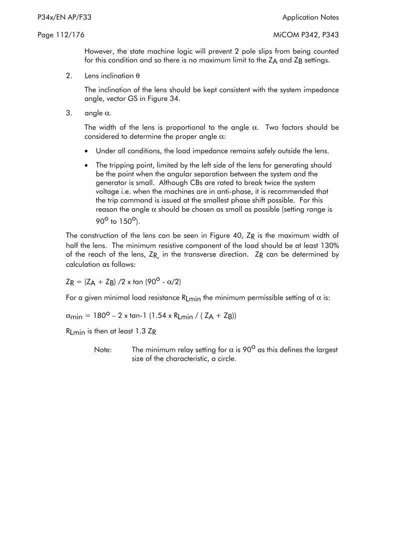
P34x/EN AP/F33 Application Notes
Page 112/176 MiCOM P342, P343
However, the state machine logic will prevent 2 pole slips from being counted for this condition and so there is no maximum limit to the ZA and ZB settings.
2. Lens inclination θ
The inclination of the lens should be kept consistent with the system impedance angle, vector GS in Figure 34.
3. angle α.
The width of the lens is proportional to the angle α. Two factors should be considered to determine the proper angle α:
• Under all conditions, the load impedance remains safely outside the lens.
• The tripping point, limited by the left side of the lens for generating should be the point when the angular separation between the system and the generator is small. Although CBs are rated to break twice the system voltage i.e. when the machines are in anti-phase, it is recommended that the trip command is issued at the smallest phase shift possible. For this reason the angle α should be chosen as small as possible (setting range is
90o to 150o).
The construction of the lens can be seen in Figure 40, ZR is the maximum width of half the lens. The minimum resistive component of the load should be at least 130% of the reach of the lens, ZR, in the transverse direction. ZR can be determined by calculation as follows:
ZR = (ZA + ZB) /2 x tan (90o - α/2)
For a given minimal load resistance RLmin the minimum permissible setting of α is:
αmin = 180o – 2 x tan-1 (1.54 x RLmin / ( ZA + ZB))
RLmin is then at least 1.3 ZR
Note: The minimum relay setting for α is 90o as this defines the largest size of the characteristic, a circle.
Application Notes P34x/EN AP/F33
MiCOM P342, P343 Page 113/176
R4
Reactance Line
R
X
R3R2R1
R represents Region
Zone2
Zone1
Blinder
Lens
Pick-Up Zone
P1256ENb
Figure 41: Pole slipping protection using blinder and lenticular characteristic
4. Reactance setting
The value of Zc
The value of Zc determines the distance of the reactance line from the origin. The reactance line provides a means of discrimination of the pole slipping within the generator or power swing within the HV power system. It should be set to encompass the step-up transformer and generator reactance with sufficient margin.
5. Pole slipping counters
Counters are available for both Zone1 and Zone2 to count the number of pole slip cycles before the trip signal is issued. A user-settable reset timer is available to reset the counters when the pole slipping condition is cleared by other relays in the system.
6. Timers T1 and T2
During a pole slip the impedance locus traverses across the lens spending at least time T1 in region 2 and time T2 in region 3, see Figures 37 and 39. From simulation testing it has been proved that pole slips up to 10 Hz can be
detected with an angle α setting of 120o and time settings of 15 ms for T1 and T2. Therefore, it is recommended that T1 and T2 be set to 15 ms.
7. Reset timer
The reset time should be set longer than the maximum expected time for the machine to go through the set number of pole slips for zone1 or zone2 . The reset time is required to reset the counters for pole slips that are cleared by external protection. For example if the Z2 counter is set to operate after 2 pole slips in the power system and after a count of 1 the condition is cleared by other protection in the system the counters will need to be reset to zero.

P34x/EN AP/F33 Application Notes
Page 114/176 MiCOM P342, P343
8. Pole slip mode
When a generator is out of step with the system, the impedance locus is expected to traverse from right to left across the lens and the blinder. However, if the generator is running as a motor, as in the pumping mode of a pump storage generator, the impedance locus is expected to swing from the left to the right. A pole slip mode setting is provided to determine whether the protection operates in a ‘generating’ mode or in a ‘motoring’ mode or ‘both’.
For a pump storage generator, its operation can switch from generating mode to motoring mode and vice versa. Therefore, a facility is provided for the protection to detect the normal running mode of the machine, generating or motoring and to perform pole slipping detection in either mode. This facility is enabled when the pole slip mode setting is set to ‘Both’.
Also, when a generator is running at low load, <30% load, due to the presence of heavy system damping during a fault the generator can slow down and result in a motor like slip (negative slip). To detect pole slips for low load and normal load conditions then the pole slip mode should be set to ‘Both’.
2.22.7.1Settings
Menu Text Default Setting Setting Range
Step Size Min Max
GROUP 1 POLE SLIPPING
Pslip Function Enabled Disabled, Enabled
Pole Slip Mode Generating Motoring, Generating, Both
Pslip Za Forward 100/Ιn Ω
0.5/Ιn Ω
(Vn=100/120V)
2/Ιn Ω
(Vn=380/480V)
350/Ιn Ω
(Vn=100/120V)
1400/Ιn Ω
(Vn=380/480V)
0.5/Ιn Ω
(Vn=100/120V)
2/Ιn Ω
(Vn=380/480V)
Pslip Zb Reverse 150/In Ω
0.5/Ιn Ω
(Vn=100/120V)
2/Ιn Ω
(Vn=380/480V)
350/Ιn Ω
(Vn=100/120V)
1400/Ιn Ω
(Vn=380/480V)
0.5/Ιn Ω
(Vn=100/120V)
2/Ιn Ω
(Vn=380/480V)
Lens Angle 120° 90° 150° 1°
PSlip Timer T1 0.015 s 0 s 1 s 0.005 s
PSlip Timer T2 0.015 s 0 s 1 s 0.005 s
Blinder Angle 75° 20° 90° 1°
PSlip Zc 50/In Ω
0.5/Ιn Ω
(Vn=100/120V)
2/Ιn Ω
(Vn=380/480V)
350/Ιn Ω
(Vn=100/120V)
1400/Ιn Ω
(Vn=380/480V)
0.5/Ιn Ω
(Vn=100/120V)
2/Ιn Ω
(Vn=380/480V)
Zone1 Slip Count 1 1 20 1
Zone2 Slip Count 2 1 20 1
PSlip Reset Time 30 s 0 s 100 s 0.01 s
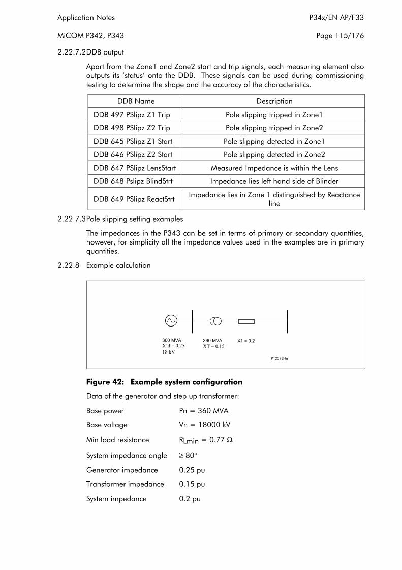
Application Notes P34x/EN AP/F33
MiCOM P342, P343 Page 115/176
2.22.7.2DDB output
Apart from the Zone1 and Zone2 start and trip signals, each measuring element also outputs its ‘status’ onto the DDB. These signals can be used during commissioning testing to determine the shape and the accuracy of the characteristics.
DDB Name Description
DDB 497 PSlipz Z1 Trip Pole slipping tripped in Zone1
DDB 498 PSlipz Z2 Trip Pole slipping tripped in Zone2
DDB 645 PSlipz Z1 Start Pole slipping detected in Zone1
DDB 646 PSlipz Z2 Start Pole slipping detected in Zone2
DDB 647 PSlipz LensStart Measured Impedance is within the Lens
DDB 648 Pslipz BlindStrt Impedance lies left hand side of Blinder
DDB 649 PSlipz ReactStrt Impedance lies in Zone 1 distinguished by Reactance line
2.22.7.3Pole slipping setting examples
The impedances in the P343 can be set in terms of primary or secondary quantities, however, for simplicity all the impedance values used in the examples are in primary quantities.
2.22.8 Example calculation
P1259ENa
X1 = 0.2 360 MVA XT = 0.15
360 MVA X’d = 0.25 18 kV
Figure 42: Example system configuration
Data of the generator and step up transformer:
Base power Pn = 360 MVA
Base voltage Vn = 18000 kV
Min load resistance RLmin = 0.77 Ω
System impedance angle ≥ 80°
Generator impedance 0.25 pu
Transformer impedance 0.15 pu
System impedance 0.2 pu

P34x/EN AP/F33 Application Notes
Page 116/176 MiCOM P342, P343
The location of the pole slipping relay is at the generator terminals. The direction of ZA and Zc is towards the step up transformer and the rest of the system. The reactance line is required to distinguish between power swings with electrical centres within the generator/transformer zone and those outside.
The base impedance is
Zbase = Vn2/Pn = 182/360 = 0.9 Ω
ZA = (XT + X1) Zbase = (0.15+0.2) x 0.9 = 0.315 Ω
ZB = 2X’d x Zbase = 2 x 0.25 x 0.9= 0.45 Ω
Zc is set to 90% of the transformer reactance
Zc = 0.9 x (XT) Zbase = 0.9 x 0.15 x 0.9 = 0.122 Ω
The minimum suitable angle α which defines the lens limit in relation to the minimum load resistance is
αmin = 180° – 2 x tan-1 (1.54 x RLmin / ( ZA + ZB))
αmin = 180° – 2 x tan-1 (1.54 x 0.77 / ( 0.315 + 0.45))
αmin = 65.7o
The minimum setting for α on the relay is 90° so this is the setting used.
T1 and T2 are set to 15 ms and θ is set to the system impedance angle of 80°
2.23 Thermal overload protection
2.23.1 Introduction
Overloads can result in stator temperature rises which exceed the thermal limit of the winding insulation. Empirical results suggest that the life of insulation is approximately halved for each 10°C rise in temperature above the rated value. However, the life of insulation is not wholly dependent upon the rise in temperature but on the time the insulation is maintained at this elevated temperature. Due to the relatively large heat storage capacity of an electrical machine, infrequent overloads of short duration may not damage the machine. However, sustained overloads of a few percent may result in premature ageing and failure of insulation.
The physical and electrical complexity of generator construction result in a complex thermal relationship. It is not therefore possible to create an accurate mathematical model of the true thermal characteristics of the machine.
However, if a generator is considered to be a homogeneous body, developing heat internally at a constant rate and dissipating heat at a rate directly proportional to its temperature rise, it can be shown that the temperature at any instant is given by:
T = Tmax (1-e-t/τ)
Where
Tmax = final steady state temperature
τ = heating time constant
This assumes a thermal equilibrium in the form:
Heat developed = Heat stored + Heat dissipated

Application Notes P34x/EN AP/F33
MiCOM P342, P343 Page 117/176
Temperature rise is proportional to the current squared:
T = K ΙR2 (1-e-t/τ)
T = Tmax = K ΙR2 if t = ∞
Where
ΙR = the continuous current level which would produce a temperature Tmax in the generator
For an overload current of ‘Ι’ the temperature is given by:
T = KΙ2 (1-e-t/τ)
For a machine not to exceed Tmax, the rated temperature, then the time ‘t’ for which the machine can withstand the current ‘Ι’ can be shown to be given by:
Tmax = K ΙR2 = KΙ2 (1-e-t/τ)
t = τ. Loge (1/(1-(ΙR/Ι)2))
An overload protection element should therefore satisfy the above relationship. The value of ΙR may be the full load current or a percentage of it depending on the design.
As previously stated it is an oversimplification to regard a generator as an homogeneous body. The temperature rise of different parts or even of various points in the same part may be very uneven. However, it is reasonable to consider that the current-time relationship follows an inverse characteristic. A more accurate representation of the thermal state of the machine can be obtained through the use of temperature monitoring devices (RTDs) which target specific areas. Also, for short time overloads the application of RTDs and overcurrent protection can provide better protection. Note, that the thermal model does not compensate for the effects of ambient temperature change. So if there is an unusually high ambient temperature or if the machine cooling is blocked RTDs will also provide better protection.
2.23.2 Thermal replica
The P343 relay models the time-current thermal characteristic of a generator by internally generating a thermal replica of the machine. The thermal overload protection can be selectively enabled or disabled. The positive and negative sequence components of the generator current are measured independently and are combined together to form an equivalent current, Ιeq, which is supplied to the replica circuit. The heating effect in the thermal replica is produced by Ιeq
2 and therefore takes into account the heating effect due to both positive and negative sequence components of current.
Unbalanced phase currents will cause additional rotor heating that may not be accounted for by some thermal protection relays based on the measured current only. Unbalanced loading results in the flow of positive and negative sequence current components. Load unbalance can arise as a result of single phase loading, nonlinear loads (involving power electronics or arc furnaces, etc.), uncleared or repetitive asymmetric faults, fuse operation, single-pole tripping and reclosing on transmission systems, broken overhead line conductors and asymmetric failures of switching devices. Any negative phase sequence component of stator current will set up a reverse-rotating component of stator flux that passes the rotor at twice synchronous speed. Such a flux component will induce double frequency eddy currents in the rotor, which can cause overheating of the rotor body, main rotor windings, damper windings etc. This extra heating is not accounted for in the thermal limit curves supplied by the generator manufacturer as these curves assume positive sequence
P34x/EN AP/F33 Application Notes
Page 118/176 MiCOM P342, P343
currents only that come from a perfectly balanced supply and generator design. The P340 thermal model may be biased to reflect the additional heating that is caused by negative sequence current when the machine is running. This biasing is done by creating an equivalent heating current rather than simply using the phase current. The M factor is a constant that relates negative sequence rotor resistance to positive sequence rotor resistance. If an M factor of 0 is used the unbalance biasing is disabled and the overload curve will time out against the measured generator positive sequence current. Note, the P340 also includes a negative sequence overcurrent protection function based on Ι2
2t specifically for thermal protection of the rotor.
The equivalent current for operation of the overload protection is in accordance with the following expression:
Ιeq = √(Ι12 + MΙ2
2)
where
Ι1 = positive sequence current
Ι2 = negative sequence current
M = a user settable constant proportional to the thermal capacity of the machine
As previously described, the temperature of a generator will rise exponentially with increasing current. Similarly, when the current decreases, the temperature also decreases in a similar manner. Therefore, in order to achieve close sustained overload protection, the P343 relay incorporates a wide range of thermal time constants for heating and cooling.
Furthermore, the thermal withstand capability of the generator is affected by heating in the winding prior to the overload. The thermal replica is designed to take account the extremes of zero pre-fault current, known as the ‘cold’ condition and the full rated pre-fault current, known as the ‘hot’ condition. With no pre-fault current the relay will be operating on the ‘cold curve’. When a generator is or has been running at full load prior to an overload the ‘hot curve’ is applicable. Therefore, during normal operation the relay will be operating between these two limits.
The following equation is used to calculate the trip time for a given current. Note that the relay will trip at a value corresponding to 100% of it’s thermal state.
The thermal time characteristic is given by:
t = τ loge (Ιeq2 – ΙP
2)/(Ιeq2 – (Thermal Ι>)2
where
t = time to trip, following application of the overload current, Ι
τ = heating time constant of the protected plant
Ιeq = equivalent current
Thermal Ι> = relay setting current
ΙP = steady state pre-load current before application of the overload
The time to trip varies depending on the load current carried before application of the overload, i.e. whether the overload was applied from 'hot” or “cold”.

Application Notes P34x/EN AP/F33
MiCOM P342, P343 Page 119/176
The thermal time constant characteristic may be rewritten as:
exp(–t/τ) = (θ – 1) / (θ – θ p)
where
θ = Ιeq2/(Thermal Ι>)2
and
θp = Ιp2/ (Thermal Ι>)2
where θ is the thermal state and is θp the prefault thermal state.
Note, that the thermal model does not compensate for the effects of ambienttemperature change.
t = τ. Loge (K2-A2/(K2-1))
Where
K = Ιeq/Thermal Ι>
A = ΙP /Thermal Ι>
The Thermal state of the machine can be viewed in the “Thermal Overload” cell inthe “MEASUREMENTS 3” column. The thermal state can be reset by selecting ‘Yes’ in the “Reset ThermalO/L” cell in “Measurements 3”. Alternatively the thermal state can be reset by energising DDB 390 “Reset ThermalO/L” via the relay PSL.
A DDB signal “Thermal O/L Trip” is also available to indicate tripping of the element (DDB 499). A further DDB signal “Thermal Alarm” is generated from the thermal alarm stage (DDB 399). The state of the DDB signal can be programmed to be viewed in the “Monitor Bit x” cells of the “COMMISSION TESTS” column in the relay.
Setting ranges for the thermal overload element are shown in the following table:
Menu Text Default Setting Setting Range
Step Size Min Max
GROUP 1: THERMAL OVERLOAD
ΙThermal Enabled Disabled, Enabled
Thermal Ι> 1.2 Ιn A 0.5 Ιn A 2.5 Ιn A 0.01 Ιn A
Thermal Alarm 90% 20% 100% 1%
T-heating 60 mins 1 min 200 mins 1 min
T-cooling 60 mins 1 min 200 mins 1 min
M Factor 0 0 10 1
2.23.3 Setting guidelines
The current setting is calculated as:
Thermal Trip = Permissible continuous loading of the plant item/CT ratio.
The heating thermal time constant should be chosen so that the overload curve is always below the thermal limits provided by the manufacturer. This will ensure that the machine is tripped before the thermal limit is reached. The relay setting, "T-heating", is in minutes.

P34x/EN AP/F33 Application Notes
Page 120/176 MiCOM P342, P343
The cooling thermal time constant should be provided by the manufacturer. However, unless otherwise specified, the cooling time constant, "T-cooling", setting should be set equal to the main heating time constant setting, T-heating”. The cooling time constant is applied when the machine is running and the load current is decreasing. It is therefore practical to assume the cooling time constant is similar to the heating time constant if information is not available from the manufacturer. When the machine is not turning the machine will normally cool significantly slower than when the rotor is turning. The relay setting, "T-cooling", is in minutes.
An alarm can be raised on reaching a thermal state corresponding to a percentage of the trip threshold. A typical setting might be "Thermal Alarm" = 70% of thermal capacity. The thermal alarm could also be used to prevent restarting of the generator until the alarm level resets. For this application a typical setting may be 20%.
The “M Factor” is used to increase the influence of negative sequence current on the thermal replica protection due to unbalanced currents. If it is required to account for the heating effect of unbalanced currents then this factor should be set equal to the ratio of negative phase sequence rotor resistance to positive sequence rotor resistance at rated speed. When an exact setting can not be calculated a setting of 3 should be used. This is a typical setting and will suffice for the majority of applications. If an M factor of 0 is used the unbalance biasing is disabled and the overload curve will time out against the measured generator positive sequence current. Note, the extra heating caused by unbalanced phase currents is not accounted for in the thermal limit curves supplied by the generator manufacturer as these curves assume positive sequence currents only that come from a perfectly balanced supply and generator design, so the default setting is 0.
2.24 Circuit breaker failure protection
Following inception of a fault one or more main protection devices will operate and issue a trip output to the circuit breaker(s) associated with the faulted circuit. Operation of the circuit breaker is essential to isolate the fault, and prevent damage/further damage to the power system. For transmission/sub-transmssion systems, slow fault clearance can also threaten system stability. It is therefore common practice to install circuit breaker failure protection, which monitors that the circuit breaker has opened within a reasonable time. If the fault current has not been interrupted following a set time delay from circuit breaker trip initiation, breaker failure protection (CBF) will operate.
CBF operation can be used to back-trip upstream circuit breakers to ensure that the fault is isolated correctly. CBF operation can also reset all start output contacts, ensuring that any blocks asserted on upstream protection are removed.
2.24.1 Breaker failure protection configurations
The circuit breaker failure protection incorporates two timers, ‘CB Fail 1 Timer’ and ‘CB Fail 2 Timer’, allowing configuration for the following scenarios:
• Simple CBF, where only ‘CB Fail 1 Timer’ is enabled. For any protection trip, the ‘CB Fail 1 Timer’ is started, and normally reset when the circuit breaker opens to isolate the fault. If breaker opening is not detected, ‘CB Fail 1 Timer’ times out and closes an output contact assigned to breaker fail (using the programmable scheme logic). This contact is used to backtrip upstream switchgear, generally tripping all infeeds connected to the same busbar section.

Application Notes P34x/EN AP/F33
MiCOM P342, P343 Page 121/176
• A re-tripping scheme, plus delayed backtripping. Here, ‘CB Fail 1 Timer’ is used to route a trip to a second trip circuit of the same circuit breaker. This requires duplicated circuit breaker trip coils, and is known as re-tripping. Should re-tripping fail to open the circuit breaker, a backtrip may be issued following an additional time delay. The backtrip uses ‘CB Fail 2 Timer’, which is also started at the instant of the initial protection element trip.
CBF elements ‘CB Fail 1 Timer’ and ‘CB Fail 2 Timer’ can be configured to operate for trips triggered by protection elements within the relay or via an external protection trip. The latter is acheived by allocating one of the relay opto-isolated inputs to ‘External Trip’ using the programmable scheme logic.
2.24.2 Reset mechanisms for breaker fail timers
It is common practice to use low set undercurrent elements in protection relays to indicate that circuit breaker poles have interrupted the fault or load current, as required. This covers the following situations:
• Where circuit breaker auxiliary contacts are defective, or cannot be relied upon to definitely indicate that the breaker has tripped.
• Where a circuit breaker has started to open but has become jammed. This may result in continued arcing at the primary contacts, with an additional arcing resistance in the fault current path. Should this resistance severely limit fault current, the initiating protection element may reset. Thus, reset of the element may not give a reliable indication that the circuit breaker has opened fully.
For any protection function requiring current to operate, the relay uses operation of undercurrent elements (Ι<) to detect that the necessary circuit breaker poles have tripped and reset the CB fail timers. However, the undercurrent elements may not be reliable methods of resetting circuit breaker fail in all applications. For example:
• Where non-current operated protection, such as under/overvoltage or under/overfrequency, derives measurements from a line connected voltage transformer. Here, Ι< only gives a reliable reset method if the protected circuit would always have load current flowing. Detecting drop-off of the initiating protection element might be a more reliable method.
• Where non-current operated protection, such as under/overvoltage or under/overfrequency, derives measurements from a busbar connected voltage transformer. Again using Ι< would rely upon the feeder normally being loaded. Also, tripping the circuit breaker may not remove the initiating condition from the busbar, and hence drop-off of the protection element may not occur. In such cases, the position of the circuit breaker auxiliary contacts may give the best reset method.
Resetting of the CBF is possible from a breaker open indication (from the relay’s pole dead logic) or from a protection reset. In these cases resetting is only allowed provided the undercurrent elements have also reset. The resetting options are summarised in the following table:
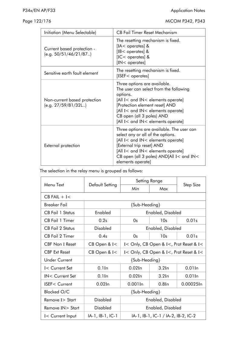
P34x/EN AP/F33 Application Notes
Page 122/176 MiCOM P342, P343
Initiation (Menu Selectable) CB Fail Timer Reset Mechanism
Current based protection (e.g. 50/51/46/21/87..)
The resetting mechanism is fixed. [ΙA< operates] & [ΙB< operates] & [ΙC< operates] & [ΙN< operates]
Sensitive earth fault element The resetting mechanism is fixed. [ΙSEF< operates]
Non-current based protection (e.g. 27/59/81/32L..)
Three options are available. The user can select from the following options. [All Ι< and ΙN< elements operate] [Protection element reset] AND [All Ι< and ΙN< elements operate] CB open (all 3 poles) AND [All Ι< and ΙN< elements operate]
External protection
Three options are available. The user can select any or all of the options. [All Ι< and ΙN< elements operate] [External trip reset] AND [All Ι< and ΙN< elements operate] CB open (all 3 poles) AND[All Ι< and ΙN< elements operate]
The selection in the relay menu is grouped as follows:
Menu Text Default Setting Setting Range
Step Size Min Max
CB FAIL + Ι<
Breaker Fail Sub-Heading
CB Fail 1 Status Enabled Enabled, Disabled
CB Fail 1 Timer 0.2s 0s 10s 0.01s
CB Fail 2 Status Disabled Enabled, Disabled
CB Fail 2 Timer 0.4s 0s 10s 0.01s
CBF Non Ι Reset CB Open & Ι< Ι< Only, CB Open & Ι<, Prot Reset & Ι<
CBF Ext Reset CB Open & Ι< Ι< Only, CB Open & Ι<, Prot Reset & Ι<
Under Current Sub-Heading
Ι< Current Set 0.1Ιn 0.02Ιn 3.2Ιn 0.01Ιn
ΙN< Current Set 0.1Ιn 0.02Ιn 3.2Ιn 0.01Ιn
ΙSEF< Current 0.02Ιn 0.001Ιn 0.8Ιn 0.00025Ιn
Blocked O/C Sub-Heading
Remove Ι> Start Disabled Enabled, Disabled
Remove ΙN> Start Disabled Enabled, Disabled
Ι< Current Input IA-1, IB-1, IC-1 IA-1, IB-1, IC-1 / IA-2, IB-2, IC-2
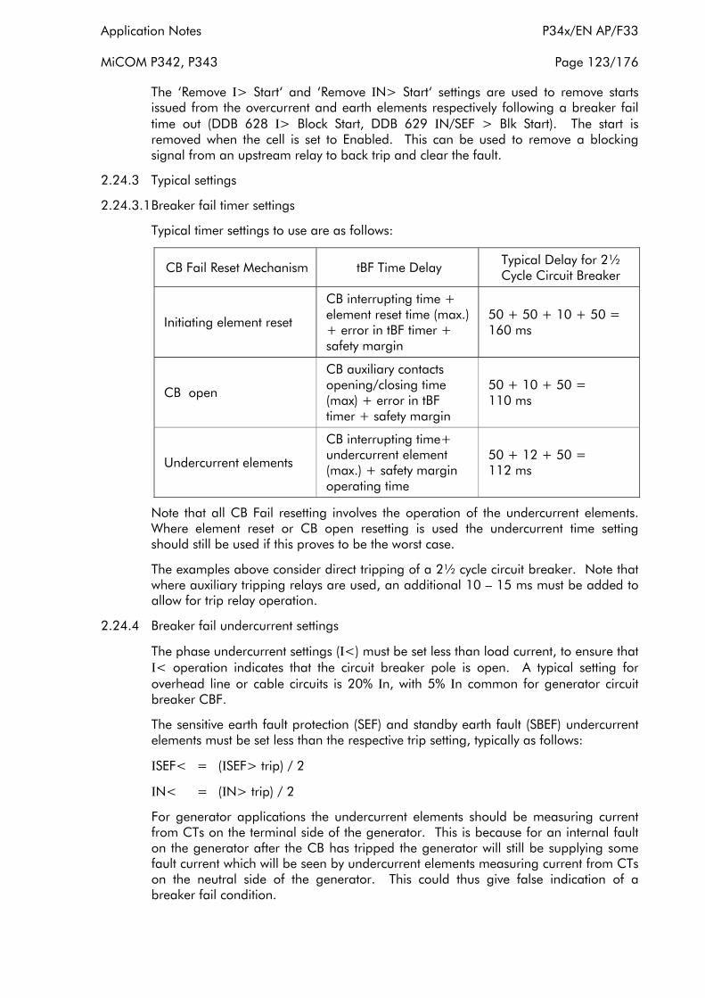
Application Notes P34x/EN AP/F33
MiCOM P342, P343 Page 123/176
The ‘Remove Ι> Start‘ and ‘Remove ΙN> Start‘ settings are used to remove starts issued from the overcurrent and earth elements respectively following a breaker fail time out (DDB 628 Ι> Block Start, DDB 629 ΙN/SEF > Blk Start). The start is removed when the cell is set to Enabled. This can be used to remove a blocking signal from an upstream relay to back trip and clear the fault.
2.24.3 Typical settings
2.24.3.1Breaker fail timer settings
Typical timer settings to use are as follows:
CB Fail Reset Mechanism tBF Time Delay Typical Delay for 2½ Cycle Circuit Breaker
Initiating element reset
CB interrupting time + element reset time (max.) + error in tBF timer + safety margin
50 + 50 + 10 + 50 = 160 ms
CB open
CB auxiliary contacts opening/closing time (max) + error in tBF timer + safety margin
50 + 10 + 50 = 110 ms
Undercurrent elements
CB interrupting time+ undercurrent element (max.) + safety margin operating time
50 + 12 + 50 = 112 ms
Note that all CB Fail resetting involves the operation of the undercurrent elements. Where element reset or CB open resetting is used the undercurrent time setting should still be used if this proves to be the worst case.
The examples above consider direct tripping of a 2½ cycle circuit breaker. Note that where auxiliary tripping relays are used, an additional 10 – 15 ms must be added to allow for trip relay operation.
2.24.4 Breaker fail undercurrent settings
The phase undercurrent settings (Ι<) must be set less than load current, to ensure that Ι< operation indicates that the circuit breaker pole is open. A typical setting for overhead line or cable circuits is 20% Ιn, with 5% Ιn common for generator circuit breaker CBF.
The sensitive earth fault protection (SEF) and standby earth fault (SBEF) undercurrent elements must be set less than the respective trip setting, typically as follows:
ΙSEF< = (ΙSEF> trip) / 2
ΙN< = (ΙN> trip) / 2
For generator applications the undercurrent elements should be measuring current from CTs on the terminal side of the generator. This is because for an internal fault on the generator after the CB has tripped the generator will still be supplying some fault current which will be seen by undercurrent elements measuring current from CTs on the neutral side of the generator. This could thus give false indication of a breaker fail condition.
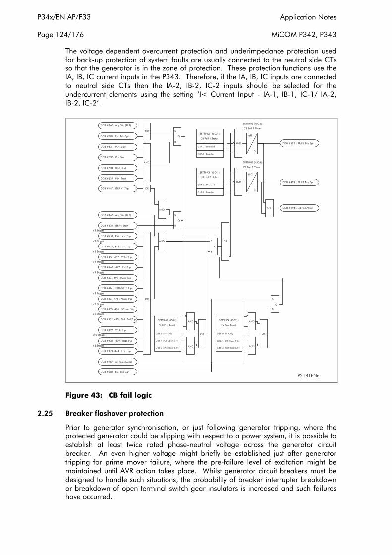
P34x/EN AP/F33 Application Notes
Page 124/176 MiCOM P342, P343
The voltage dependent overcurrent protection and underimpedance protection used for back-up protection of system faults are usually connected to the neutral side CTs so that the generator is in the zone of protection. These protection functions use the IA, IB, IC current inputs in the P343. Therefore, if the IA, IB, IC inputs are connected to neutral side CTs then the IA-2, IB-2, IC-2 inputs should be selected for the undercurrent elements using the setting ‘I< Current Input - IA-1, IB-1, IC-1/ IA-2, IB-2, IC-2’.
Figure 43: CB fail logic
2.25 Breaker flashover protection
Prior to generator synchronisation, or just following generator tripping, where the protected generator could be slipping with respect to a power system, it is possible to establish at least twice rated phase-neutral voltage across the generator circuit breaker. An even higher voltage might briefly be established just after generator tripping for prime mover failure, where the pre-failure level of excitation might be maintained until AVR action takes place. Whilst generator circuit breakers must be designed to handle such situations, the probability of breaker interrupter breakdown or breakdown of open terminal switch gear insulators is increased and such failures have occurred.
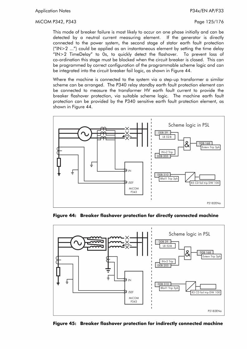
Application Notes P34x/EN AP/F33
MiCOM P342, P343 Page 125/176
This mode of breaker failure is most likely to occur on one phase initially and can be detected by a neutral current measuring element. If the generator is directly connected to the power system, the second stage of stator earth fault protection (“ΙN>2 ...”) could be applied as an instantaneous element by setting the time delay “ΙN>2 TimeDelay” to 0s, to quickly detect the flashover. To prevent loss of co-ordination this stage must be blocked when the circuit breaker is closed. This can be programmed by correct configuration of the programmable scheme logic and can be integrated into the circuit breaker fail logic, as shown in Figure 44.
Where the machine is connected to the system via a step-up transformer a similar scheme can be arranged. The P340 relay standby earth fault protection element can be connected to measure the transformer HV earth fault current to provide the breaker flashover protection, via suitable scheme logic. The machine earth fault protection can be provided by the P340 sensitive earth fault protection element, as shown in Figure 44.
Figure 44: Breaker flashover protection for directly connected machine
Figure 45: Breaker flashover protection for indirectly connected machine
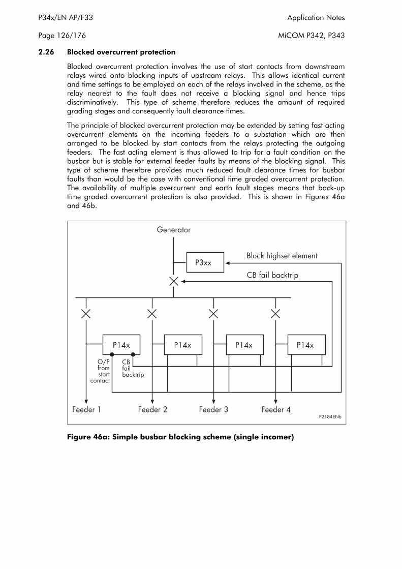
P34x/EN AP/F33 Application Notes
Page 126/176 MiCOM P342, P343
2.26 Blocked overcurrent protection
Blocked overcurrent protection involves the use of start contacts from downstream relays wired onto blocking inputs of upstream relays. This allows identical current and time settings to be employed on each of the relays involved in the scheme, as the relay nearest to the fault does not receive a blocking signal and hence trips discriminatively. This type of scheme therefore reduces the amount of required grading stages and consequently fault clearance times.
The principle of blocked overcurrent protection may be extended by setting fast acting overcurrent elements on the incoming feeders to a substation which are then arranged to be blocked by start contacts from the relays protecting the outgoing feeders. The fast acting element is thus allowed to trip for a fault condition on the busbar but is stable for external feeder faults by means of the blocking signal. This type of scheme therefore provides much reduced fault clearance times for busbar faults than would be the case with conventional time graded overcurrent protection. The availability of multiple overcurrent and earth fault stages means that back-up time graded overcurrent protection is also provided. This is shown in Figures 46a and 46b.
Figure 46a: Simple busbar blocking scheme (single incomer)

Application Notes P34x/EN AP/F33
MiCOM P342, P343 Page 127/176
Figure 46b: Simple busbar blocking scheme (single incomer)
The P140/P340 relays have start outputs available from each stage of each of the overcurrent and earth fault elements, including sensitive earth fault. These start signals may then be routed to output contacts by programming accordingly. Each stage is also capable of being blocked by being programmed to the relevant optoisolated input.
Note that the P340 relays provide a 50V field supply for powering the opto-inputs. Hence, in the unlikely event of the faulure of this supply, blocking of that relay would not be possible. For this reason, the field supply is supervised and if a failure is detected, it is possible, via the relays programmable scheme logic, to provide an output alarm contact. This contact can then be used to signal an alarm within the substation. Alternatively, the relays scheme logic could be arranged to block any of the overcurrent/earth fault stages that would operate non-discriminatively due to the blocking signal failure.
For further guidance on the use of blocked overcurrent schemes refer to AREVA T&D.
2.27 Current loop inputs and outputs
2.27.1 Current loop inputs
Four analogue (or current loop) inputs are provided for transducers with ranges of 01mA, 0-10mA, 0-20mA or 4-20mA. The analogue inputs can be used for various transducers such as vibration monitors, tachometers and pressure transducers. Associated with each input there are two protection stages, one for alarm and one for trip. Each stage can be individually enabled or disabled and each stage has a definite time delay setting. The Alarm and Trip stages can be set for operation when the input value falls below the Alarm/Trip threshold ‘Under’ or when the input current is above the input value ‘Over’. The sample interval is nominally 50ms per input.
The relationship between the transducer measuring range and the current input range is linear. The maximum and minimum settings correspond to the limits of the current input range. This relationship is shown in Figure 47.

P34x/EN AP/F33 Application Notes
Page 128/176 MiCOM P342, P343
Figure 47 also shows the relationship between the measured current and the analogue to digital conversion (ADC) count. The hardware design allows for over-ranging, with the maximum ADC count (4095 for a 12-bit ADC) corresponding to 1.0836mA for the 0-1mA range, and 22.7556mA for the 0-10mA, 0-20mA and 4-20mA ranges. The relay will therefore continue to measure and display values beyond the Maximum setting, within its numbering capability (-9999 to 9999).
Minimum
Maximum
Minimum
Maximum
0mA
0 4095
ADC Count
22.7556mA 20mA Current I/P
0mA
0 4095
ADC Count
22.7556mA 20mA
Minimum
Maximum
Current I/P 4mA
1.0836mA 0mA
0 4095
ADC Count
22.7556mA
Minimum
Maximum
Current I/P 10mA
0-10mA
0-20mA 4-20mA
Transducer Value
Transducer Value
Transducer Value
0mA
0 4095
ADC Count
1mA Current I/P
0-1mA
Transducer Value
P1417ENa
Figure 47: Relationship between the transducer measuring quantity and the current input range
Note, if the Maximum is set less than the Minimum, the slopes of the graphs will be negative. This is because the mathematical relationship remains the same irrespective of how Maximum and Minimum are set, e.g., for 0-1mA range, Maximum always corresponds to 1mA and Minimum corresponds to 0mA.
Power-on diagnostics and continuous self-checking are provided for the hardware associated with the current loop inputs. When a failure is detected, the protection associated with all the current loop inputs is disabled and a single alarm signal (CL Card I/P Fail, DDB 320) is set and an alarm (CL Card I/P Fail) is raised. A maintenance record with an error code is also recorded with additional details about the type of failure.
For the 4-20mA input range, a current level below 4mA indicates that there is a fault with the transducer or the wiring. An instantaneous under current alarm element is available, with a setting range from 0 to 4mA. This element controls an output signal (CLI1/2/3/4 I< Fail Alm, DDB 326-329) which can be mapped to a user defined alarm if required.
Hysteresis is implemented for each protection element. For ‘Over’ protection, the drop-off/pick-up ratio is 95%, for ‘Under’ protection, the ratio is 105%.

Application Notes P34x/EN AP/F33
MiCOM P342, P343 Page 129/176
Each current loop input can be blocked by energising the relevant DDB signal via the PSL, (CL Input 1/2/3/4 Blk, DDB 393-396). If a current loop input is blocked the protection and alarm stages and 4-20mA undercurrent alarm associated with that input are blocked. The blocking signals may be useful for blocking the current loop inputs when the CB is open for example.
DDB signals are available to indicate starting an operation of the alarm and trip stages of the each current loop inputs, (CLI1/2/3/4 Alarm Start: DDB 658-661, CLI1/2/3/4 Trip Start: DDB 662-665, CL Input 1/2/3/4 Alarm: DDB 322-325, CLI Input1/2/3/4 Trip: DDB 508-511). The state of the DDB signals can be programmed to be viewed in the “Monitor Bit x” cells of the “COMMISSION TESTS” column in the relay.
Setting ranges for the current loop inputs are shown in the following table:
Menu Text Default Setting
Setting Range Step Size
Min Max
GROUP 1 CLIO PROTECTION
CLIO Input 1 Disabled Disabled/Enabled
CLI1 Input Type 4-20mA 0-1mA, 0-10mA, 0-20mA, 4-20mA
CLI1 Input Label CLIO Input 1 16 characters
CLI1 Minimum 0 -9999 9999 0.1
CLI1 Maximum 100 -9999 9999 0.1
CLI1 Alarm Disabled Disabled/Enabled
CLI1 Alarm Fn Over Over/Under
CLI1 Alarm Set 50 Min (CLI1 Min, Max)
Max (CLI1 Min, Max) 0.1
CLI1 Alarm Delay 1 0 100s 0.1s
CLI1 Trip Disabled Disabled/Enabled
CLI1 Trip Fn Over Over/Under
CLI1 Trip Set 50 Min (CLI1 Min, Max)
Max (CLI1 Min, Max) 0.1
CLI1 Trip Delay 1 0 100s 0.1s
CLI1 I< Alarm (420 mA input only) Disabled Disabled/Enabled
CLI1 I< Alm Set (420 mA input only) 3.5 mA 0 4 mA 0.1 mA
Repeat for current loop inputs 2, 3 and 4
2.27.2 Setting guidelines for current loop inputs
For each analogue input, the user can define the following:
• The current input range: 0-1mA, 0-10mA, 0-20mA, 4-20mA
• The Analogue Input function and unit, this is in the form of a 16-character Input Label

P34x/EN AP/F33 Application Notes
Page 130/176 MiCOM P342, P343
• Analogue Input Minimum Value (setting range from –9999 to 9999)
• Analogue Input Maximum Value (setting range from –9999 to 9999)
• Alarm threshold, range within the Maximum and Minimum set values
• Alarm Function – Over or Under
• Alarm Delay
• Trip Threshold, range within Maximum and Minimum set values
• Trip Function – Over or Under
• Trip delay
Each current loop input can be selected as Enabled or Disabled as can the Alarm and Trip stage of each of the current loop input. The Alarm and Trip stages can be set for operation when the input value falls below the Alarm/Trip threshold ‘Under’ or when the input current is above the input value ‘Over’ depending on the application. One of four types of analogue inputs can be selected for transducers with ranges of 0-1mA, 0-10mA, 0-20mA or 4-20mA.
The Maximum and Minimum settings allow the user to enter the range of physical or electrical quantities measured by the transducer. The settings are unit-less; however, the user can enter the transducer function and the unit of the measurement using the 16-character user defined CLI Input Label. For example, if the Analogue Input is used to monitor a power measuring transducer, the appropriate text could be “Active Power(MW)”.
The alarm and trip threshold settings should be set within the range of physical or electrical quantities defined by the user. The relay will convert the current input value into its corresponding transducer measuring value for the protection calculation. For example if the CLI Minimum is –1000 and the CLI Maximum is 1000 for a 0-10mA input, an input current of 10mA is equivalent to a measurement value of 1000, 5mA is 0 and 1mA is –800. If the CLI Minimum is 1000 and the CLI Maximum is -1000 for a 0-10mA input, an input current of 10mA is equivalent to a measurement value of –1000, 5mA is 0 and 1mA is 800. These values are available for display in the ‘CLIO Input 1/2/3/4’ cells in the ‘MEASUREMENTS 3’ menu. The top line shows the CLI Input Label and the bottom line shows the measurement value.
2.27.3 Current loop outputs
Four analogue current outputs are provided with ranges of 0-1mA, 0-10mA, 0-20mA or 4-20mA which can alleviate the need for separate transducers. These may be used to feed standard moving coil ammeters for analogue indication of certain measured quantities or into a SCADA using an existing analogue RTU.
The CLIO output conversion task runs every 50ms and the refresh interval for the output measurements is nominally 50ms. The exceptions are marked with an asterisk in the table of current loop output parameters below. Those exceptional measurements are updated once every second.
The outputs can be assigned to any of the following relay measurements:
• Magnitudes of IA, IB, IC, IN, IN Derived, I Sensitive
• Magnitudes of I1, I2, I0
• IA RMS, IB RMS, IC RMS
• Magnitudes of VAB, VBC, VCA, VAN, VBN, VCN, VN Measured, VN Derived

Application Notes P34x/EN AP/F33
MiCOM P342, P343 Page 131/176
• Magnitudes of V1, V2 and V0
• VAN RMS, VBN RMS, VCN RMS
• Frequency
• Single Phase Active, reactive and apparent power, single phase power factor
• 3 phase active, reactive and apparent power, single phase power factor
• VN 3rd Harmonic (P343 only)
• Stator thermal state
• Rotor (NPS) thermal state (P342/P343 only)
• RTD temperatures (P342/P343 only)
• Analogue Inputs
The user can set the measuring range for each analogue output. The range limits are defined by the Maximum and Minimum settings. This allows the user to “zoom in” and monitor a restricted range of the measurements with the desired resolution. For voltage, current and power quantities, these settings can be set in either primary or secondary quantities, depending on the ‘CLO1/2/3/4 Set Values – Primary / Secondary’ setting associated with each current loop output.
The output current of each analogue output is linearly scaled to its range limits, as defined by the Maximum and Minimum settings. The relationship is shown in Figure 48.
0mA
1mA
Minimum Maximum
0-1mA Relay
Measure-ment
Current Output
0mA
10mA
Minimum Maximum
0-10mA Relay
Measure-ment
Current Output
0mA
20mA
Minimum Maximum
0-20mA Relay
Measure-ment
Current Output
0mA
20mA
Minimum Maximum
4-20mA Relay
Measure-ment
Current Output
4mA
P1418ENa
Figure 48: Relationship between the current output and the relay measurement

P34x/EN AP/F33 Application Notes
Page 132/176 MiCOM P342, P343
Note, if the Maximum is set less than the Minimum, the slopes of the graphs will be negative. This is because the mathematical relationship remains the same irrespective of how Maximum and Minimum are set, e.g., for 0-1mA range, Maximum always corresponds to 1mA and Minimum corresponds to 0mA.
The P340 transducers are of the current output type. This means that the correct value of output will be maintained over the load range specified. The range of load resistance varies a great deal, depending on the design and the value of output current. Transducers with a full scale output of 10mA will normally feed any load up to a value of 1000Ω (compliance voltage of 10V). This equates to a cable length of 15km (approximately) for lightweight cable (1/0.6mm cable). A screened cable earthed at one end only is recommended to reduce interference on the output current signal. The table below gives typical cable impedances/km for common cables. The compliance voltage dictates the maximum load that can be fed by a transducer output. Therefore, the 20mA output will be restricted to a maximum load of 500Ω approximately.
Cable 1/0.6mm 1/0.85mm 1/1.38mm
CSA (mm2) 0.28 0.57 1.50
R (Ω/km) 65.52 32.65 12.38
The receiving equipment, whether it be a simple moving-coil (DC milli-ammeter) instrument or a remote terminal unit forming part of a SCADA system, can be connected at any point in the output loop and additional equipment can be installed at a later date (provided the compliance voltage is not exceeded) without any need for adjustment of the transducer output.
Where the output current range is used for control purposes, it is sometimes worthwhile to fit appropriately rated diodes, or Zener diodes, across the terminals of each of the units in the series loop to guard against the possibility of their internal circuitry becoming open circuit. In this way, a faulty unit in the loop does not cause all the indications to disappear because the constant current nature of the transducer output simply raises the voltage and continues to force the correct output signal round the loop.
Power-on diagnostics and continuous self-checking are provided for the hardware associated with the current loop outputs. When failure is detected, all the current loop output functions are disabled and a single alarm signal (CL Card O/P Fail, DDB 321) is set and an alarm (CL Card O/P Fail) is raised. A maintenance record with an error code is also recorded with additional details about the type of failure.
Setting ranges for the Current Loop Outputs are shown in the following table:
Menu Text Default Setting Setting Range
Step Size Min Max
GROUP 1 CLIO PROTECTION
CLIO Output 1 Disabled Enabled, Disabled
CLO1 Output Type 4-20mA 0-1mA, 0-10mA, 0-20mA, 4-20mA
CLO1 Set Values Primary Primary, Secondary
CLO1 Parameter IA Magnitude A list of parameters are shown in the table below
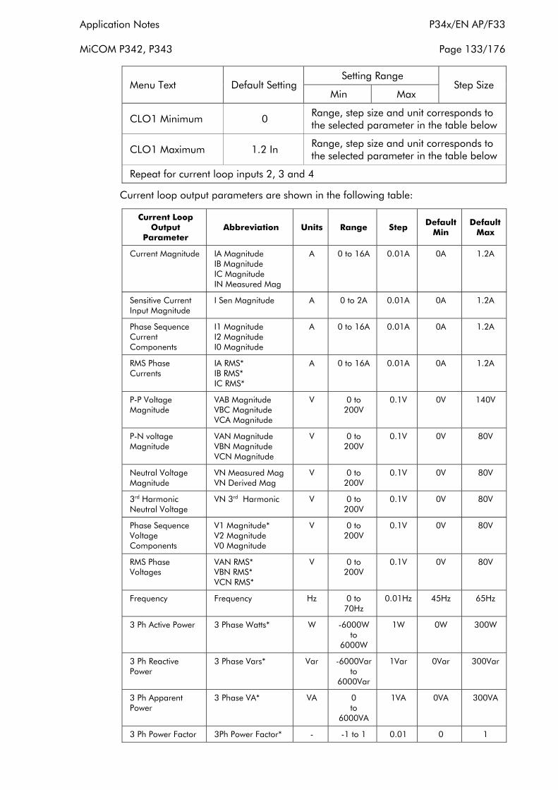
Application Notes P34x/EN AP/F33
MiCOM P342, P343 Page 133/176
Menu Text Default Setting Setting Range
Step Size Min Max
CLO1 Minimum 0 Range, step size and unit corresponds to the selected parameter in the table below
CLO1 Maximum 1.2 In Range, step size and unit corresponds to the selected parameter in the table below
Repeat for current loop inputs 2, 3 and 4
Current loop output parameters are shown in the following table:
Current Loop Output
Parameter Abbreviation Units Range Step
Default Min
Default Max
Current Magnitude IA Magnitude IB Magnitude IC Magnitude IN Measured Mag
A 0 to 16A 0.01A 0A 1.2A
Sensitive Current Input Magnitude
I Sen Magnitude A 0 to 2A 0.01A 0A 1.2A
Phase Sequence I1 Magnitude A 0 to 16A 0.01A 0A 1.2A Current I2 Magnitude Components I0 Magnitude
RMS Phase IA RMS* A 0 to 16A 0.01A 0A 1.2A Currents IB RMS*
IC RMS*
P-P Voltage VAB Magnitude V 0 to 0.1V 0V 140V Magnitude VBC Magnitude 200V
VCA Magnitude
P-N voltage VAN Magnitude V 0 to 0.1V 0V 80V Magnitude VBN Magnitude 200V
VCN Magnitude
Neutral Voltage Magnitude
VN Measured Mag VN Derived Mag
V 0 to 200V
0.1V 0V 80V
3rd Harmonic Neutral Voltage
VN 3rd Harmonic V 0 to 200V
0.1V 0V 80V
Phase Sequence V1 Magnitude* V 0 to 0.1V 0V 80V Voltage V2 Magnitude 200V Components V0 Magnitude
RMS Phase VAN RMS* V 0 to 0.1V 0V 80V Voltages VBN RMS* 200V
VCN RMS*
Frequency Frequency Hz 0 to 70Hz
0.01Hz 45Hz 65Hz
3 Ph Active Power 3 Phase Watts* W -6000W 1W 0W 300W to
6000W
3 Ph Reactive 3 Phase Vars* Var -6000Var 1Var 0Var 300Var Power to
6000Var
3 Ph Apparent 3 Phase VA* VA 0 1VA 0VA 300VA Power to
6000VA
3 Ph Power Factor 3Ph Power Factor* - -1 to 1 0.01 0 1

P34x/EN AP/F33 Application Notes
Page 134/176 MiCOM P342, P343
Current Loop Output
Parameter Abbreviation Units Range Step
Default Min
Default Max
Single Phase Active A Phase Watts* W -2000W 1W 0W 100W Power B Phase Watts* to
C Phase Watts* 2000W
Single Phase A Phase Vars* Var -2000Var 1Var 0Var 100Var Reactive Power B Phase Vars* to
C Phase Vars* 2000Var
Single Phase A Phase VA* VA 0 1VA 0VA 100VA Apparent Power B Phase VA* to
C Phase VA* 2000VA
Single Phase Power APh Power Factor* -1 to 1 0.01 0 1 Factor BPh Power Factor*
CPh Power Factor*
3 Phase Current Demands
IA Fixed Demand* IB Fixed Demand* IC Fixed Demand* IA Roll Demand* IB Roll Demand* IC Roll Demand* IA Peak Demand* IB Peak Demand* IC Peak Demand*
A 0 to 16A 0.01A 0A 1.2A
3Ph Active Power 3Ph W Fix W -6000W 1W 0W 300W Demands Demand* to
3Ph W Roll Dem* 6000W 3Ph W Peak Dem*
3Ph Reactive Power 3Ph Vars Fix Dem* Var -6000Var 1Var 0Var 300Var Demands 3Ph Var Roll Dem* to
3Ph Var Peak Dem* 6000Var
Rotor Thermal State
NPS Thermal % 0 to 200 0.01 0 120
Stator Thermal State
Thermal Overload % 0 to 200 0.01 0 120
RTD Temperatures RTD 1* RTD 2*
°C -40°C to
0.1°C 0°C 200°C
RTD 3* 300°C RTD 4* RTD 5* RTD 6* RTD 7* RTD 8* RTD 9* RTD 10*
Current Loop CL Input 1 - -9999 0.1 0 9999 Inputs CL Input 2 to
CL Input 3 9999 CL input 4
Note 1: For measurements marked with an asterisk, the internal refresh rate is nominally 1s, others are 0.5 power system cycle or less.
Note 2: The polarity of Watts, Vars and power factor is affected by the Measurements Mode setting.
Note 3: These settings are for nominal 1A and 100/120V versions only. For other nominal versions they need to be multiplied accordingly.

Application Notes P34x/EN AP/F33
MiCOM P342, P343 Page 135/176
Note 4: For the P343, the IA/IB/IC Current magnitudes are IA-1 Magnitude, IB-1 Magnitude, IC-1 Magnitude.
2.27.4 Setting guidelines for current loop outputs
Each current loop output can be selected as Enabled or Disabled. One of four types of analogue output can be selected for transducers with ranges of 0-1mA, 0-10mA, 0-20mA or 4-20mA. The 4-20mA range is often used so that an output current is still present when the measured value falls to zero. This is to give a fail safe indication and may be used to distinguish between the analogue transducer output becoming faulty and the measurement falling to zero.
The Maximum and Minimum settings allow the user to enter the measuring range for each analogue output. The range, step size and unit corresponding to the selected parameter is shown in the table above. This allows the user to “zoom in” and monitor a restricted range of the measurements with the desired resolution. For voltage, current and power quantities, these settings can be set in either primary or secondary quantities, depending on the ‘CLO1/2/3/4 Set Values – Primary / Secondary’ setting associated with each current loop output.
The relationship of the output current to the value of the measurand is of vital importance and needs careful consideration. Any receiving equipment must, of course, be used within its rating but, if possible, some kind of standard should be established.
One of the objectives must be to have the capability to monitor the voltage over a range of values, so an upper limit must be selected, typically 120%. However, this may lead to difficulties in scaling an instrument.
The same considerations apply to current transducers outputs and with added complexity to watt transducers outputs, where both the voltage and current transformer ratios must be taken into account.
Some of these difficulties do not need to be considered if the transducer is only feeding, for example, a SCADA outstation. Any equipment which can be programmed to apply a scaling factor to each input individually can accommodate most signals. The main consideration will be to ensure that the transducer is capable of providing a signal right up to the full-scale value of the input, that is, it does not saturate at the highest expected value of the measurand.
3. APPLICATION OF NON-PROTECTION FUNCTIONS
3.1 VT supervision
The voltage transformer supervision (VTS) feature is used to detect failure of the ac voltage inputs to the relay. This may be caused by internal voltage transformer faults, overloading, or faults on the interconnecting wiring to relays. This usually results in one or more VT fuses blowing. Following a failure of the ac voltage input there would be a misrepresentation of the phase voltages on the power system, as measured by the relay, which may result in maloperation.
The VTS logic in the relay is designed to detect the voltage failure, and automatically adjust the configuration of protection elements whose stability would otherwise be compromised. A time-delayed alarm output is also available.
There are three main aspects to consider regarding the failure of the VT supply. These are defined below:

P34x/EN AP/F33 Application Notes
Page 136/176 MiCOM P342, P343
1. Loss of one or two phase voltages
2. Loss of all three phase voltages under load conditions
3. Absence of three phase voltages upon line energisation
The VTS feature within the relay operates on detection of negative phase sequence (nps) voltage without the presence of negative phase sequence current. This gives operation for the loss of one or two phase voltages. Stability of the VTS function is assured during system fault conditions, by the presence of nps current. The use of negative sequence quantities ensures correct operation even where three-limb or ‘V’ connected VT’s are used.
Negative sequence VTS element:
The negative sequence thresholds used by the element are V2 = 10V (Vn = 100/120V) or 40V (Vn = 380/480V), and Ι2 = 0.05 to 0.5Ιn settable (defaulted to 0.05Ιn).
3.1.1 Loss of all three phase voltages under load conditions
Under the loss of all three phase voltages to the relay, there will be no negative phase sequence quantities present to operate the VTS function. However, under such circumstances, a collapse of the three phase voltages will occur. If this is detected without a corresponding change in any of the phase current signals (which would be indicative of a fault), then a VTS condition will be raised. In practice, the relay detects the presence of superimposed current signals, which are changes in the current applied to the relay. These signals are generated by comparison of the present value of the current with that exactly one cycle previously. Under normal load conditions, the value of superimposed current should therefore be zero. Under a fault condition a superimposed current signal will be generated which will prevent operation of the VTS.
The phase voltage level detectors are fixed and will drop off at 10V (Vn = 100/120V), 40V (Vn = 380/480V) and pick-up at 30V (Vn = 100/120V), 120V (Vn = 380/480V).
The sensitivity of the superimposed current elements is fixed at 0.1Ιn.
3.1.2 Absence of three phase voltages upon line energisation
If a VT were inadvertently left isolated prior to line energisation, incorrect operation of voltage dependent elements could result. The previous VTS element detected three phase VT failure by absence of all 3 phase voltages with no corresponding change in current. On line energisation there will, however, be a change in current (as a result of load or line charging current for example). An alternative method of detecting 3 phase VT failure is therefore required on line energisation.
The absence of measured voltage on all 3 phases on line energisation can be as a result of 2 conditions. The first is a 3 phase VT failure and the second is a close up three phase fault. The first condition would require blocking of the voltage dependent function and the second would require tripping. To differentiate between these 2 conditions an overcurrent level detector (VTS Ι> Inhibit) is used which will prevent a VTS block from being issued if it operates. This element should be set in excess of any non-fault based currents on line energisation (load, line charging current, transformer inrush current if applicable) but below the level of current produced by a close up 3 phase fault. If the line is now closed where a 3 phase VT failure is present the overcurrent detector will not operate and a VTS block will be applied. Closing onto a three phase fault will result in operation of the overcurrent detector and prevent a VTS block being applied.

Application Notes P34x/EN AP/F33
MiCOM P342, P343 Page 137/176
This logic will only be enabled during a live line condition (as indicated by the relays pole dead logic) to prevent operation under dead system conditions i.e. where no voltage will be present and the VTS Ι> Inhibit overcurrent element will not be picked up.
Note: The accelerated ind input is not used in the generator protection.
Figure 49: VTS logic
Required to drive the VTS logic are a number of dedicated level detectors as follows:
• ΙA>, ΙB>, ΙC>, these level detectors operate in less than 20ms and their settings should be greater than load current. This setting is specified as the VTS current threshold. These level detectors pick-up at 100% of setting and drop-off at 95% of setting.
• Ι2>, this level detector operates on negative sequence current and has a user setting. This level detector picks-up at 100% of setting and drops-off at 95% of setting.
• ∆ΙIA>, ∆ΙB>, ∆ΙC>, these level detectors operate on superimposed phase currents and have a fixed setting of 10% of nominal. These level detectors are subject to a count strategy such that 0.5 cycle of operate decisions must have occured before operation.
• VA>, VB>, VC>, these level detectors operate on phase voltages and have a fixed setting, Pick-up level = 30V (Vn = 100/120V), 120V (Vn = 380/480V), Drop Off level = 10V (Vn = 100/120V), 40V (Vn = 380/480V).
• V2>, this level detector operates on negative sequence voltage, it has a fixed setting of 10V/40V depending on VT rating (100/120 or 380/480) with pick-up at 100% of setting and drop-off at 95% of setting.
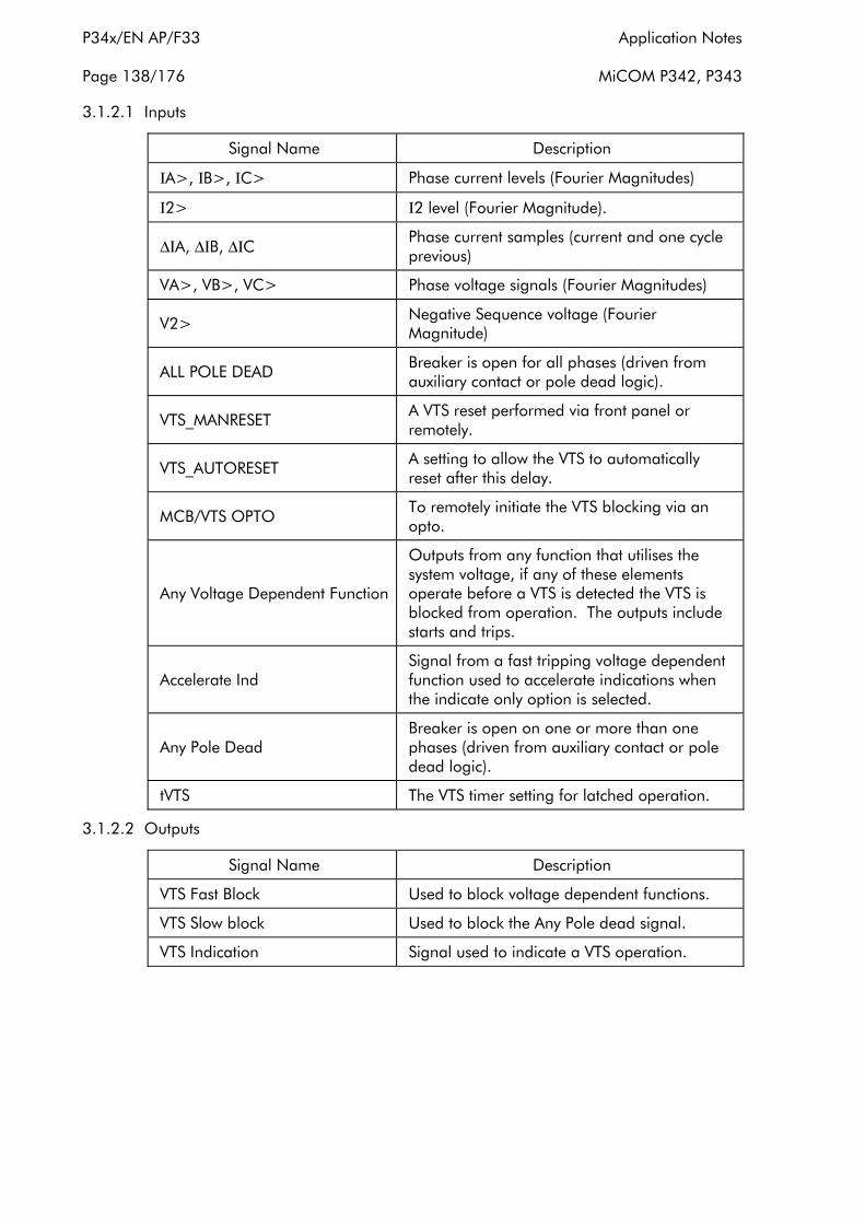
P34x/EN AP/F33 Application Notes
Page 138/176 MiCOM P342, P343
3.1.2.1 Inputs
Signal Name Description
ΙA>, ΙB>, ΙC> Phase current levels (Fourier Magnitudes)
Ι2> Ι2 level (Fourier Magnitude).
∆ΙA, ∆ΙB, ∆ΙC Phase current samples (current and one cycle previous)
VA>, VB>, VC> Phase voltage signals (Fourier Magnitudes)
V2> Negative Sequence voltage (Fourier Magnitude)
ALL POLE DEAD Breaker is open for all phases (driven from auxiliary contact or pole dead logic).
VTS_MANRESET A VTS reset performed via front panel or remotely.
VTS_AUTORESET A setting to allow the VTS to automatically reset after this delay.
MCB/VTS OPTO To remotely initiate the VTS blocking via an opto.
Any Voltage Dependent Function
Outputs from any function that utilises the system voltage, if any of these elements operate before a VTS is detected the VTS is blocked from operation. The outputs include starts and trips.
Accelerate Ind Signal from a fast tripping voltage dependent function used to accelerate indications when the indicate only option is selected.
Any Pole Dead Breaker is open on one or more than one phases (driven from auxiliary contact or pole dead logic).
tVTS The VTS timer setting for latched operation.
3.1.2.2 Outputs
Signal Name Description
VTS Fast Block Used to block voltage dependent functions.
VTS Slow block Used to block the Any Pole dead signal.
VTS Indication Signal used to indicate a VTS operation.
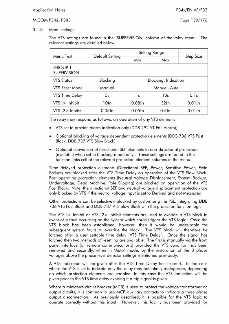
Application Notes P34x/EN AP/F33
MiCOM P342, P343 Page 139/176
3.1.3 Menu settings
The VTS settings are found in the ‘SUPERVISION’ column of the relay menu. The relevant settings are detailed below:
Menu Text Default Setting Setting Range
Step Size Min Max
GROUP 1 SUPERVISION
VTS Status Blocking Blocking, Indication
VTS Reset Mode Manual Manual, Auto
VTS Time Delay 5s 1s 10s 0.1s
VTS Ι> Inhibit 10Ιn 0.08Ιn 32Ιn 0.01Ιn
VTS Ι2> Inhibit 0.05Ιn 0.05Ιn 0.5Ιn 0.01Ιn
The relay may respond as follows, an operation of any VTS element:
• VTS set to provide alarm indication only (DDB 292 VT Fail Alarm);
• Optional blocking of voltage dependent protection elements (DDB 736 VTS Fast Block, DDB 737 VTS Slow Block);
• Optional conversion of directional SEF elements to non-directional protection (available when set to blocking mode only). These settings are found in the function links cell of the relevant protection element columns in the menu.
Time delayed protection elements (Directional SEF, Power, Sensitive Power, Field Failure) are blocked after the VTS Time Delay on operation of the VTS Slow Block. Fast operating protection elements (Neutral Voltage Displacement, System Backup, Undervoltage, Dead Machine, Pole Slipping) are blocked on operation of the VTS Fast Block. Note, the directional SEF and neutral voltage displacement protection are only blocked by VTS if the neutral voltage input is set to Derived and not Measured.
Other protections can be selectively blocked by customising the PSL, integrating DDB 736 VTS Fast Block and DDB 737 VTS Slow Block with the protection function logic.
The VTS Ι> Inhibit or VTS Ι2> Inhibit elements are used to overide a VTS block in event of a fault occurring on the system which could trigger the VTS logic. Once the VTS block has been established, however, then it would be undesirable for subsequent system faults to override the block. The VTS block will therefore be latched after a user settable time delay ‘VTS Time Delay’. Once the signal has latched then two methods of resetting are available. The first is manually via the front panel interface (or remote communications) provided the VTS condition has been removed and secondly, when in ‘Auto’ mode, by the restoration of the 3 phase voltages above the phase level detector settings mentioned previously.
A VTS indication will be given after the VTS Time Delay has expired. In the case where the VTS is set to indicate only the relay may potentially maloperate, depending on which protection elements are enabled. In this case the VTS indication will be given prior to the VTS time delay expiring if a trip signal is given.
Where a miniature circuit breaker (MCB) is used to protect the voltage transformer ac output circuits, it is common to use MCB auxiliary contacts to indicate a three phase output disconnection. As previously described, it is possible for the VTS logic to operate correctly without this input. However, this facility has been provided for

P34x/EN AP/F33 Application Notes
Page 140/176 MiCOM P342, P343
compatibility with various utilities current practices. Energising an opto-isolated input assigned to “MCB Open” on the relay will therefore provide the necessary block.
Where directional SEF elements are converted to non-directional protection on VTS operation, it must be ensured that the current pick-up setting of these elements is higher than full load current.
3.2 CT supervision
The current transformer supervision feature is used to detect failure of one or more of the ac phase current inputs to the relay. Failure of a phase CT or an open circuit of the interconnecting wiring can result in incorrect operation of any current operated element. Additionally, interruption in the ac current circuits risks dangerous CT secondary voltages being generated.
3.2.1 The CT supervision feature
The CT supervision feature operates on detection of derived residual current, in the absence of corresponding derived or measured residual voltage that would normally accompany it.
The CT supervision can be set to operate from the residual voltage measured at the VNEUTRAL input or the residual voltage derived from the 3 phase-neutral voltage inputs as selected by the ‘CTS Vn Input’ setting.
The voltage transformer connection used must be able to refer residual voltages from the primary to the secondary side. Thus, this element should only be enabled where the 3 phase VT is of five limb construction, or comprises three single phase units, and has the primary star point earthed. A derived residual voltage or a measured residual voltage is available.
Operation of the element will produce a time-delayed alarm visible on the LCD and event record (plus DDB 293: CT Fail Alarm), with an instantaneous block (DDB 738: CTS Block) for inhibition of protection elements. Protection elements operating from derived quantities, (Neg Seq O/C) are always blocked on operation of the CT supervision element; other protections can be selectively blocked by customising the PSL, integrating DDB 738: CTS Block with the protection function logic.
Figure 50: CT supervision function block diagram
The following table shows the relay menu for the CT supervision element, including the available setting ranges and factory defaults:

Application Notes P34x/EN AP/F33
MiCOM P342, P343 Page 141/176
Menu Text Default Setting Setting Range
Step Size Min Max
GROUP 1 SUPERVISION
CT Supervision Sub Heading
CTS Status Disabled Enabled/Disabled N/A
CTS VN Input Derived Derived/Measured N/A
CTS VN< Inhibit 1 0.5/2V For 110/440V respectively
22/88V For 110/440V respectively 0.5/2V For 110/440V respectively
CTS ΙN> Set 0 0.08 x Ιn 4 x Ιn 0.01 x Ιn
CTS Time Delay 5 0s 10s 1s
3.2.2 Setting the CT supervision element
The residual voltage setting, "CTS Vn< Inhibit" and the residual current setting, "CTS Ιn> set", should be set to avoid unwanted operation during healthy system conditions. For example "CTS Vn< Inhibit" should be set to 120% of the maximum steady state residual voltage. The "CTS Ιn> set" will typically be set below minimum load current. The time-delayed alarm, "CTS Time Delay", is generally set to 5 seconds.
Where the magnitude of residual voltage during an earth fault is unpredictable, the element can be disabled to prevent a protection elements being blocked during fault conditions.
3.3 Circuit breaker state monitoring
An operator at a remote location requires a reliable indication of the state of the switchgear. Without an indication that each circuit breaker is either open or closed, the operator has insufficient information to decide on switching operations. The relay incorporates circuit breaker state monitoring, giving an indication of the position of the circuit breaker, or, if the state is unknown, an alarm is raised.
3.3.1 Circuit breaker state monitoring features
MiCOM relays can be set to monitor normally open (52a) and normally closed (52b) auxiliary contacts of the circuit breaker. Under healthy conditions, these contacts will be in opposite states. Should both sets of contacts be open, this would indicate one of the following conditions:
• Auxiliary contacts/wiring defective
• Circuit Breaker (CB) is defective
• CB is in isolated position
Should both sets of contacts be closed, only one of the following two conditions would apply:
• Auxiliary contacts/wiring defective
• Circuit Breaker (CB) is defective

P34x/EN AP/F33 Application Notes
Page 142/176 MiCOM P342, P343
If any of the above conditions exist, an alarm will be issued after a 5s time delay. A normally open / normally closed output contact can be assigned to this function via the programmable scheme logic (PSL). The time delay is set to avoid unwanted operation during normal switching duties.
In the CB CONTROL column of the relay menu there is a setting called ‘CB Status Input’. This cell can be set at one of the following four options:
None
52A
52B
Both 52A and 52B
Where ‘None’ is selected no CB status will be available. This will directly affect any function within the relay that requires this signal, for example CB control, autoreclose, etc. Where only 52A is used on its own then the relay will assume a 52B signal from the absence of the 52A signal. Circuit breaker status information will be available in this case but no discrepancy alarm will be available. The above is also true where only a 52B is used. If both 52A and 52B are used then status information will be available and in addition a discrepancy alarm will be possible, according to the following table. 52A and 52B inputs are assigned to relay opto-isolated inputs via the PSL. The CB State Monitoring logic is shown in Figure 51).
Auxiliary Contact Position CB State Detected Action
52A 52B
Open Closed Breaker Open Circuit breaker healthy
Closed Open Breaker Closed Circuit breaker healthy
Closed Closed CB Failure Alarm raised if the condition persists for greater than 5s
Open Open State Unknown Alarm raised if the condition persists for greater than 5s
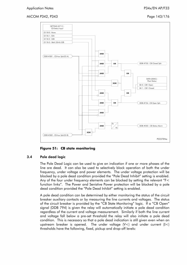
Application Notes P34x/EN AP/F33
MiCOM P342, P343 Page 143/176
Figure 51: CB state monitoring
3.4 Pole dead logic
The Pole Dead Logic can be used to give an indication if one or more phases of the line are dead. It can also be used to selectively block operation of both the under frequency, under voltage and power elements. The under voltage protection will be blocked by a pole dead condition provided the “Pole Dead Inhibit” setting is enabled. Any of the four under frequency elements can be blocked by setting the relevant “F< function links”. The Power and Senistive Power protection will be blocked by a pole dead condition provided the “Pole Dead Inhibit” setting is enabled.
A pole dead condition can be determined by either monitoring the status of the circuit breaker auxiliary contacts or by measuring the line currents and voltages. The status of the circuit breaker is provided by the “CB State Monitoring” logic. If a “CB Open” signal (DDB 794) is given the relay will automatically initiate a pole dead condition regardless of the current and voltage measurement. Similarly if both the line current and voltage fall below a pre-set threshold the relay will also initiate a pole dead condition. This is necessary so that a pole dead indication is still given even when an upstream breaker is opened. The under voltage (V<) and under current (Ι<) thresholds have the following, fixed, pickup and drop-off levels:
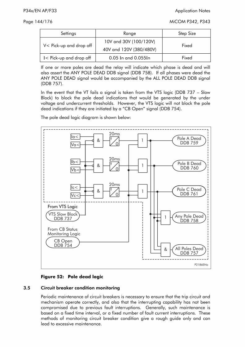
P34x/EN AP/F33 Application Notes
Page 144/176 MiCOM P342, P343
Settings Range Step Size
V< Pick-up and drop off 10V and 30V (100/120V)
40V and 120V (380/480V) Fixed
Ι< Pick-up and drop off 0.05 Ιn and 0.055Ιn Fixed
If one or more poles are dead the relay will indicate which phase is dead and will also assert the ANY POLE DEAD DDB signal (DDB 758). If all phases were dead the ANY POLE DEAD signal would be accompanied by the ALL POLE DEAD DDB signal (DDB 757).
In the event that the VT fails a signal is taken from the VTS logic (DDB 737 – Slow Block) to block the pole dead indications that would be generated by the under voltage and undercurrent thresholds. However, the VTS logic will not block the pole dead indications if they are initiated by a “CB Open” signal (DDB 754).
The pole dead logic diagram is shown below:
Figure 52: Pole dead logic
3.5 Circuit breaker condition monitoring
Periodic maintenance of circuit breakers is necessary to ensure that the trip circuit and mechanism operate correctly, and also that the interrupting capability has not been compromised due to previous fault interruptions. Generally, such maintenance is based on a fixed time interval, or a fixed number of fault current interruptions. These methods of monitoring circuit breaker condition give a rough guide only and can lead to excessive maintenance.

Application Notes P34x/EN AP/F33
MiCOM P342, P343 Page 145/176
The P340 relays record various statistics related to each circuit breaker trip operation, allowing a more accurate assessment of the circuit breaker condition to be determined. These monitoring features are discussed in the following section.
3.5.1 Circuit breaker condition monitoring features
For each circuit breaker trip operation the relay records statistics as shown in the following table taken from the relay menu. The menu cells shown are counter values only. The Min/Max values in this case show the range of the counter values. These cells can not be set:
Menu Text Default Setting Setting Range
Step Size Min Max
CB CONDITION
CB operations 3 pole tripping 0 0 10000 1
Total ΙA Broken 0 0 25000Ιn^ 1
Total ΙB Broken 0 0 25000Ιn^ 1
Total ΙC Broken 0 0 25000Ιn^ 1Ιn^
CB operate time 0 0 0.5s 0.001
Reset CB Data No Yes, No
The above counters may be reset to zero, for example, following a maintenance inspection and overhaul.
The following table, detailing the options available for the CB condition monitoring, is taken from the relay menu. It includes the set up of the current broken facility and those features which can be set to raise an alarm or CB lockout.
Menu Text Default Setting Setting Range
Step Size Min Max
CB MONITOR SETUP
Broken Ι^ 2 1 2 0.1
Ι^ Maintenance Alarm disabled Alarm disabled, Alarm enabled
Ι^ Maintenance 1000Ιn^ 1Ιn^ 25000Ιn^ 1Ιn^
Ι^ Lockout Alarm disabled Alarm disabled, Alarm enabled
Ι^ Lockout 2000Ιn^ 1Ιn^ 25000Ιn^ 1Ιn^
No CB Ops. Maint. Alarm disabled Alarm disabled, Alarm enabled
No CB Ops. Maint. 10 1 10000 1
No CB Ops. Lock Alarm disabled Alarm disabled, Alarm enabled
No CB Ops. Lock 20 1 10000 1
CB Time Maint. Alarm disabled Alarm disabled, Alarm enabled
CB Time Maint. 0.1s 0.005s 0.5s 0.001s
CB Time Lockout Alarm disabled Alarm disabled, Alarm enabled
CB Time Lockout 0.2s 0.005s 0.5s 0.001s
P34x/EN AP/F33 Application Notes
Page 146/176 MiCOM P342, P343
Menu Text Default Setting Setting Range
Step Size Min Max
Fault Freq. Lock Alarm disabled Alarm disabled, Alarm enabled
Fault Freq. Count 10 1 9999 1
Fault Freq. Time 3600s 0 9999s 1s
The circuit breaker condition monitoring counters will be updated every time the relay issues a trip command. In cases where the breaker is tripped by an external protection device it is also possible to update the CB condition monitoring. This is achieved by allocating one of the relays opto-isolated inputs (via the programmable scheme logic) to accept a trigger from an external device. The signal that is mapped to the opto is called ‘Ext Trip 3Ph’, DDB 380.
Note that when in Commissioning test mode the CB condition monitoring counters will not be updated.
3.5.2 Setting guidelines
3.5.2.1 Setting the Σ Ι^ thresholds
Where overhead lines are prone to frequent faults and are protected by oil circuit breakers (OCB’s), oil changes account for a large proportion of the life cycle cost of the switchgear. Generally, oil changes are performed at a fixed interval of circuit breaker fault operations. However, this may result in premature maintenance where fault currents tend to be low, and hence oil degradation is slower than expected. The Σ Ι^ counter monitors the cumulative severity of the duty placed on the interrupter allowing a more accurate assessment of the circuit breaker condition to be made.
For OCB’s, the dielectric withstand of the oil generally decreases as a function of Σ Ι2t. This is where ‘Ι’ is the fault current broken, and ‘t’ is the arcing time within the interrupter tank (not the interrupting time). As the arcing time cannot be determined accurately, the relay would normally be set to monitor the sum of the broken current squared, by setting ‘Broken Ι^’ = 2.
For other types of circuit breaker, especially those operating on higher voltage systems, practical evidence suggests that the value of ‘Broken Ι^’ = 2 may be inappropriate. In such applications ‘Broken Ι^’ may be set lower, typically 1.4 or 1.5. An alarm in this instance may be indicative of the need for gas/vacuum interrupter HV pressure testing, for example.
The setting range for ‘Broken Ι^’ is variable between 1.0 and 2.0 in 0.1 steps. It is imperative that any maintenance programme must be fully compliant with the switchgear manufacturer’s instructions.
3.5.2.2 Setting the number of operations thresholds
Every operation of a circuit breaker results in some degree of wear for its components. Thus, routine maintenance, such as oiling of mechanisms, may be based upon the number of operations. Suitable setting of the maintenance threshold will allow an alarm to be raised, indicating when preventative maintenance is due. Should maintenance not be carried out, the relay can be set to lockout the autoreclose function on reaching a second operations threshold. This prevents further reclosure when the circuit breaker has not been maintained to the standard demanded by the switchgear manufacturer’s maintenance instructions.
Application Notes P34x/EN AP/F33
MiCOM P342, P343 Page 147/176
Certain circuit breakers, such as oil circuit breakers (OCB’s) can only perform a certain number of fault interruptions before requiring maintenance attention. This is because each fault interruption causes carbonising of the oil, degrading its dielectric properties. The maintenance alarm threshold "No CB Ops Maint" may be set to indicate the requirement for oil sampling for dielectric testing, or for more comprehensive maintenance. Again, the lockout threshold "No CB Ops Lock" may be set to disable autoreclosure when repeated further fault interruptions could not be guaranteed. This minimises the risk of oil fires or explosion.
3.5.2.3 Setting the operating time thresholds
Slow CB operation is also indicative of the need for mechanism maintenance. Therefore, alarm and lockout thresholds (CB Time Maint/CB Time Lockout) are provided and are settable in the range of 5 to 500ms. This time is set in relation to the specified interrupting time of the circuit breaker.
3.5.2.4 Setting the excessive fault frequency thresholds
A circuit breaker may be rated to break fault current a set number of times before maintenance is required. However, successive circuit breaker operations in a short period of time may result in the need for increased maintenance. For this reason it is possible to set a frequent operations counter on the relay which allows the number of operations "Fault Freq Count" over a set time period "Fault Freq Time" to be monitored. A separate alarm and lockout threshold can be set.
3.5.3 Circuit breaker state monitoring features
MiCOM relays can be set to monitor normally open (52a) and normally closed (52b) auxiliary contacts of the circuit breaker. Under healthy conditions, these contacts will be in opposite states. Should both sets of contacts be open, this would indicate one of the following conditions:
• Auxiliary contacts / wiring defective
• Circuit Breaker (CB) is defective
• CB is in isolated position
Should both sets of contacts be closed, only one of the following two conditions would apply:
• Auxiliary contacts / wiring defective
• Circuit Breaker (CB) is defective
Menu Text Default Setting Setting Range
Step Size Min Max
CB Time Maint 0.1s 0.005s 0.5s 0.001s
CB Time Lockout Alarm disabled Alarm disabled, Alarm enabled
CB Time Lockout 0.2s 0.005s 0.5s 0.001s
Fault Freq Lock Alarm disabled Alarm disabled, Alarm enabled
Fault Freq Count 10 0 9999 1
Fault Freq Time 3600s 0 9999s 1s
The circuit breaker condition monitoring counters will be updated every time the relay issues a trip command. In cases where the breaker is tripped by an external protection device it is also possible to update the CB condition monitoring. This is
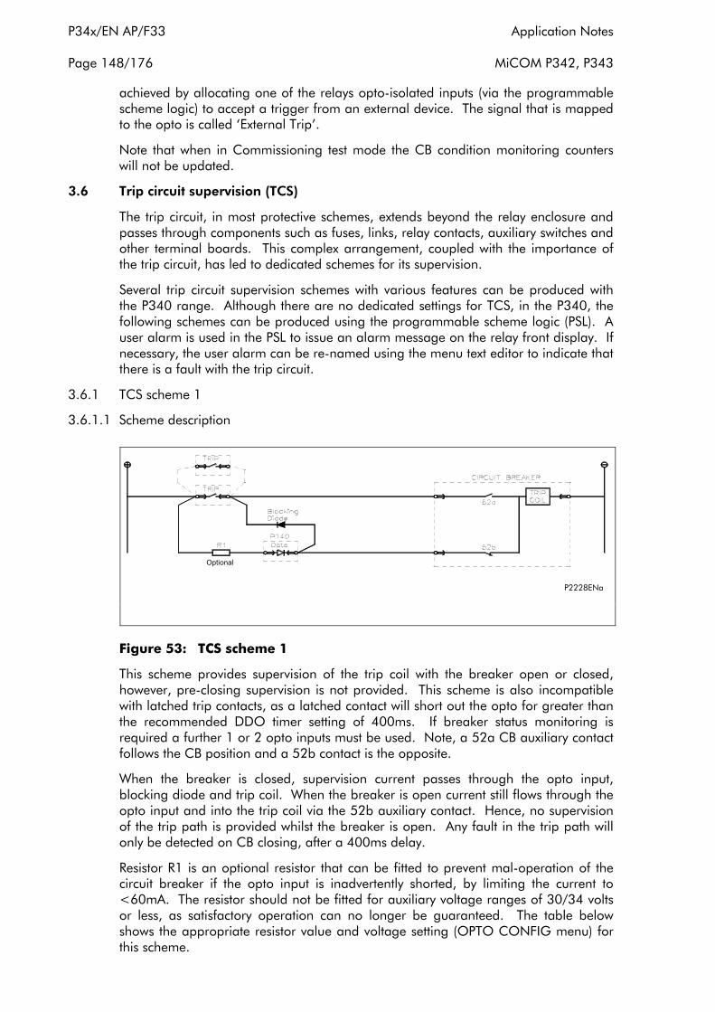
P34x/EN AP/F33 Application Notes
Page 148/176 MiCOM P342, P343
achieved by allocating one of the relays opto-isolated inputs (via the programmable scheme logic) to accept a trigger from an external device. The signal that is mapped to the opto is called ‘External Trip’.
Note that when in Commissioning test mode the CB condition monitoring counters will not be updated.
3.6 Trip circuit supervision (TCS)
The trip circuit, in most protective schemes, extends beyond the relay enclosure and passes through components such as fuses, links, relay contacts, auxiliary switches and other terminal boards. This complex arrangement, coupled with the importance of the trip circuit, has led to dedicated schemes for its supervision.
Several trip circuit supervision schemes with various features can be produced with the P340 range. Although there are no dedicated settings for TCS, in the P340, the following schemes can be produced using the programmable scheme logic (PSL). A user alarm is used in the PSL to issue an alarm message on the relay front display. If necessary, the user alarm can be re-named using the menu text editor to indicate that there is a fault with the trip circuit.
3.6.1 TCS scheme 1
3.6.1.1 Scheme description
P2228ENa
Optional
Figure 53: TCS scheme 1
This scheme provides supervision of the trip coil with the breaker open or closed, however, pre-closing supervision is not provided. This scheme is also incompatible with latched trip contacts, as a latched contact will short out the opto for greater than the recommended DDO timer setting of 400ms. If breaker status monitoring is required a further 1 or 2 opto inputs must be used. Note, a 52a CB auxiliary contact follows the CB position and a 52b contact is the opposite.
When the breaker is closed, supervision current passes through the opto input, blocking diode and trip coil. When the breaker is open current still flows through the opto input and into the trip coil via the 52b auxiliary contact. Hence, no supervision of the trip path is provided whilst the breaker is open. Any fault in the trip path will only be detected on CB closing, after a 400ms delay.
Resistor R1 is an optional resistor that can be fitted to prevent mal-operation of the circuit breaker if the opto input is inadvertently shorted, by limiting the current to <60mA. The resistor should not be fitted for auxiliary voltage ranges of 30/34 volts or less, as satisfactory operation can no longer be guaranteed. The table below shows the appropriate resistor value and voltage setting (OPTO CONFIG menu) for this scheme.

Application Notes P34x/EN AP/F33
MiCOM P342, P343 Page 149/176
This TCS scheme will function correctly even without resistor R1, since the opto input automatically limits the supervision current to less that 10mA. However, if the opto is accidentally shorted the circuit breaker may trip.
Auxiliary Voltage (Vx) Resistor R1 (ohms) Opto Voltage Setting with R1 Fitted
24/27 - -
30/34 - -
48/54 1.2k 24/27
110/250 2.5k 48/54
220/250 5.0k 110/125
Note: When R1 is not fitted the opto voltage setting must be set equal to supply voltage of the supervision circuit.
3.6.2 Scheme 1 PSL
Figure 54 shows the scheme logic diagram for the TCS scheme 1. Any of the available opto inputs can be used to indicate whether or not the trip circuit is healthy. The delay on drop off timer operates as soon as the opto is energised, but will take 400ms to drop off / reset in the event of a trip circuit failure. The 400ms delay prevents a false alarm due to voltage dips caused by faults in other circuits or during normal tripping operation when the opto input is shorted by a self-reset trip contact. When the timer is operated the NC (normally closed) output relay opens and the LED and user alarms are reset.
The 50ms delay on pick-up timer prevents false LED and user alarm indications during the relay power up time, following an auxiliary supply interruption.
Figure 54: PSL for TCS schemes 1 and 3
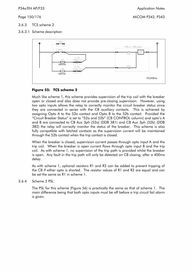
P34x/EN AP/F33 Application Notes
Page 150/176 MiCOM P342, P343
3.6.3 TCS scheme 2
3.6.3.1 Scheme description
Optional
Optional
P2230ENa
Figure 55: TCS scheme 2
Much like scheme 1, this scheme provides supervision of the trip coil with the breaker open or closed and also does not provide pre-closing supervision. However, using two opto inputs allows the relay to correctly monitor the circuit breaker status since they are connected in series with the CB auxiliary contacts. This is achieved by assigning Opto A to the 52a contact and Opto B to the 52b contact. Provided the “Circuit Breaker Status” is set to “52a and 52b” (CB CONTROL column) and opto’s A and B are connected to CB Aux 3ph (52a) (DDB 381) and CB Aux 3ph (52b) (DDB 382) the relay will correctly monitor the status of the breaker. This scheme is also fully compatible with latched contacts as the supervision current will be maintained through the 52b contact when the trip contact is closed.
When the breaker is closed, supervision current passes through opto input A and the trip coil. When the breaker is open current flows through opto input B and the trip coil. As with scheme 1, no supervision of the trip path is provided whilst the breaker is open. Any fault in the trip path will only be detected on CB closing, after a 400ms delay.
As with scheme 1, optional resistors R1 and R2 can be added to prevent tripping of the CB if either opto is shorted. The resistor values of R1 and R2 are equal and can be set the same as R1 in scheme 1.
3.6.4 Scheme 2 PSL
The PSL for this scheme (Figure 56) is practically the same as that of scheme 1. The main difference being that both opto inputs must be off before a trip circuit fail alarm is given.

Application Notes P34x/EN AP/F33
MiCOM P342, P343 Page 151/176
Figure 56: PSL for TCS scheme 2
3.6.5 TCS scheme 3
3.6.5.1 Scheme description
P2231ENa
Figure 57: TCS scheme 2
Scheme 3 is designed to provide supervision of the trip coil with the breaker open or closed, but unlike schemes 1 and 2, it also provides pre-closing supervision. Since only one opto input is used, this scheme is not compatible with latched trip contacts. If circuit breaker status monitoring is required a further 1 or 2 opto inputs must be used.
When the breaker is closed, supervision current passes through the opto input, resistor R1 and the trip coil. When the breaker is open current flows through the opto input, resistors R1 and R2 (in parallel), resistor R3 and the trip coil. Unlike schemes 1 and 2, supervision current is maintained through the trip path with the breaker in either state, thus giving pre-closing supervision.
As with schemes 1 and 2, resistors R1 and R2 are used to prevent false tripping, if the opto-input is accidentally shorted. However, unlike the other two schemes, this scheme is dependent upon the position and value of these resistors. Removing them would result in incomplete trip circuit monitoring. The table below shows the resistor values and voltage settings required for satisfactory operation.

P34x/EN AP/F33 Application Notes
Page 152/176 MiCOM P342, P343
Auxiliary Voltage (Vx)
Resistor R1 & R2 (ohms) Resistor R3 (ohms) Opto Voltage
Setting
24/27 - - -
30/34 - - -
48/54 1.2k 0.6k 24/27
110/250 2.5k 1.2k 48/54
220/250 5.0k 2.5k 110/125
Note: Scheme 3 is not compatible with auxiliary supply voltages of 30/34 volts and below.
3.6.6 Scheme 3 PSL
The PSL for scheme 3 is identical to that of scheme 1 (see Figure 53).
3.7 Event & fault records
The relay records and time tags up to 250 events and stores them in non-volatile (battery backed up) memory. This enables the system operator to establish the sequence of events that occurred within the relay following a particular power system condition, switching sequence etc. When the available space is exhausted, the oldest event is automatically overwritten by the new one.
The real time clock within the relay provides the time tag to each event, to a resolution of 1ms.
The event records are available for viewing either via the frontplate LCD or remotely, via the communications ports.
Local viewing on the LCD is achieved in the menu column entitled ‘VIEW RECORDS’. This column allows viewing of event, fault and maintenance records and is shown below:
VIEW RECORDS
LCD Reference Description
Select Event Setting range from 0 to 249. This selects the required event record from the possible 250 that may be stored. A value of 0 corresponds to the latest event and so on.
Time & Date Time & Date Stamp for the event given by the internal Real Time Clock
Event Text Up to 32 Character description of the Event (refer to following sections)
Event Value Up to 32 Bit Binary Flag representative of the Event (refer to following sections)
Select Fault Setting range from 0 to 4. This selects the required fault record from the possible 5 that may be stored. A value of 0 corresponds to the latest fault and so on.
The following cells show all the fault flags, protection starts, protection trips, fault location, measurements etc. associated with the fault, i.e. the complete fault record.
Application Notes P34x/EN AP/F33
MiCOM P342, P343 Page 153/176
VIEW RECORDS
LCD Reference Description
Select Maint. Setting range from 0 to 4. This selects the required maintenance record from the possible 5 that may be stored. A value of 0 corresponds to the latest record and so on.
Maint. Text Up to 32 Character description of the occurrence (refer to following sections).
Maint. Type These cells are numbers representative of the occurrence. They form a specific error code which should be quoted in any related correspondence to AREVA T&D.
Maint. Data
Reset Indication Either Yes or No. This serves to reset the trip LED indications provided that the relevant protection element has reset.
For extraction from a remote source via communications, refer to SCADA Communications (P34x/EN CT/E33), where the procedure is fully explained.
Note that a full list of all the event types and the meaning of their values is given in document P34x/EN GC/E33.
Types of Event
An event may be a change of state of a control input or output relay, an alarm condition, setting change etc. The following sections show the various items that constitute an event:
3.7.1 Change of state of opto-isolated inputs
If one or more of the opto (logic) inputs has changed state since the last time that the protection algorithm ran, the new status is logged as an event. When this event is selected to be viewed on the LCD, three applicable cells will become visible as shown below:
Time & Date of Event
“LOGIC INPUTS”
“Event Value 0101010101010101”
The Event Value is an 8 or 16 bit word showing the status of the opto inputs, where the least significant bit (extreme right) corresponds to opto input 1 etc. The same information is present if the event is extracted and viewed via PC.
3.7.2 Change of state of one or more output relay contacts
If one or more of the output relay contacts has changed state since the last time that the protection algorithm ran, then the new status is logged as an event. When this event is selected to be viewed on the LCD, three applicable cells will become visible as shown below:
P34x/EN AP/F33 Application Notes
Page 154/176 MiCOM P342, P343
Time & Date of Event
“OUTPUT CONTACTS”
“Event Value 010101010101010101010”
The Event Value is a 7, 14 or 21 bit word showing the status of the output contacts, where the least significant bit (extreme right) corresponds to output contact 1 etc. The same information is present if the event is extracted and viewed via PC.
3.7.3 Relay alarm conditions
Any alarm conditions generated by the relays will also be logged as individual events. The following table shows examples of some of the alarm conditions and how they appear in the event list:
Alarm Condition Resulting Event
Event Text Event Value
Alarm Status 1 (Alarms 1-32) (32 bits)
Setting Group Via Opto Invalid
Setting Grp Invalid ON/OFF Bit position 2 in 32 bit field
Protection Disabled Prot’n Disabled ON/OFF Bit position 3 in 32 bit field
Frequency Out of Range Freq out of Range ON/OFF Bit position 13 in 32 bit field
VTS Alarm VT Fail Alarm ON/OFF Bit position 4 in 32 bit field
CB Trip Fail Protection CB Fail ON/OFF Bit position 6 in 32 bit field
Alarm Status 2 (Alarms 1-32) (32 bits)
SR User Alarm 1-4 (Self Reset) SR User Alarm 1-4 ON/OFF Bit position 17-31 in 32 bit field
MR User Alarm 5-16 (Manual Reset)
MR User Alarm 5-16 ON/OFF
Bit position 16-27 in 32 bit field
Alarm Status 3 (Alarms 1-32) (32 bits)
Battery Fail Battery Fail ON/OFF Bit position 0 in 32 bit field
Field Voltage Fail Field V Fail ON/OFF Bit position 1 in 32 bit field
The previous table shows the abbreviated description that is given to the various alarm conditions and also a corresponding value which displays alarms as bit positions in a 32 bit field. The bit will be set to 1 if the alarm is ON and 0 if it is OFF. This value is appended to each alarm event in a similar way as for the input and output events previously described. It is used by the event extraction software, such as MiCOM S1, to identify the alarm and is therefore invisible if the event is viewed on the LCD. Either ON or OFF is shown after the description to signify whether the particular condition has become operated or has reset.
The User Alarms can be operated from an opto input or a control input using the PSL. They can thus be useful to give an alarm led and message on the LCD display and an alarm indication via the communications of an external condition, for example trip circuit supervision alarm, rotor earth fault alarm. The menu text editor in MiCOM S1 can be used to edit the user alarm text to give a more meaningful description on the LCD display.
Application Notes P34x/EN AP/F33
MiCOM P342, P343 Page 155/176
3.7.4 Protection element starts and trips
Any operation of protection elements, (either a start or a trip condition), will be logged as an event record, consisting of a text string indicating the operated element and an event value. Again, this value is intended for use by the event extraction software, such as MiCOM S1, rather than for the user, and is therefore invisible when the event is viewed on the LCD.
3.7.5 General events
A number of events come under the heading of ‘General Events’ – an example is shown below:
Nature of Event Displayed Text in Event Record Displayed Value
Level 1 password modified, either from user interface, front or rear port
PW1 modified UI, F or R 6, 11, 16 respectively
A complete list of the ‘General Events’ is given in document P34x/EN GC/E33.
3.7.6 Fault records
Each time a fault record is generated, an event is also created. The event simply states that a fault record was generated, with a corresponding time stamp.
Note that viewing of the actual fault record is carried out in the ‘Select Fault’ cell further down the ‘VIEW RECORDS’ column, which is selectable from up to 5 records. These records consist of fault flags, fault measurements etc. Also note that the time stamp given in the fault record itself will be more accurate than the corresponding stamp given in the event record as the event is logged some time after the actual fault record is generated.
The fault record is triggered from the ‘Fault REC TRIG’ signal assigned in the default programmable scheme logic to relay 3, protection trip. Note, the fault measurements in the fault record are given at the time of the protection start. Also, the fault recorder does not stop recording until any start or relay 3 (protection trip) resets in order to record all the protection flags during the fault.
It is recommended that the triggering contact (relay 3 for example) be ‘self reset’ and not latching. If a latching contact was chosen the fault record would not be generated until the contact had fully reset.
3.7.7 Maintenance reports
Internal failures detected by the self monitoring circuitry, such as watchdog failure, field voltage failure etc. are logged into a maintenance report. The Maintenance Report holds up to 5 such ‘events’ and is accessed from the ‘Select Maint.’ cell at the bottom of the ‘VIEW RECORDS’ column.
Each entry consists of a self explanatory text string and a ‘Type’ and ‘Data’ cell, which are explained in the menu extract at the beginning of this section and in further detail in document P34x/EN GC/E33.
Each time a Maintenance Report is generated, an event is also created. The event simply states that a report was generated, with a corresponding time stamp.
3.7.8 Setting changes
Changes to any setting within the relay are logged as an event. Two examples are shown in the following table:

P34x/EN AP/F33 Application Notes
Page 156/176 MiCOM P342, P343
Type of Setting Change Displayed Text in Event Record Displayed Value
Control/Support Setting C & S Changed 22
Group 1 Change Group 1 Changed 24
Note: Control/Support settings are communications, measurement, CT/VT ratio settings etc. which are not duplicated within the four setting groups. When any of these settings are changed, the event record is created simultaneously. However, changes to protection or disturbance recorder settings will only generate an event once the settings have been confirmed at the ‘setting trap’.
3.7.9 Resetting of event/fault records
If it is required to delete either the event, fault or maintenance reports, this may be done from within the ‘RECORD CONTROL’ column.
3.7.10 Viewing event records via MiCOM S1 support software
When the event records are extracted and viewed on a PC they look slightly different than when viewed on the LCD. The following shows an example of how various events appear when displayed using MiCOM S1:
- Monday 08 January 2001 18:45:28.633 GMT V<1 Trip A/AB ON
ALSTOM : MiCOM P343
Model Number: P343314B2A0020A
Address: 001 Column: 0F Row: 26
Event Type: Setting event
Event Value: 00000001000000000000000000000000
- Monday 08 January 2001 18:45:28.634 GMT Output Contacts
ALSTOM : MiCOM P343
Model Number: P343314B2A0020A
Address: 001 Column: 00 Row: 21
Event Type: Device output changed state
Event Value: 00000000001100
OFF 0 R1 Trip CB
OFF 1 R2 Trip PrimeMov
ON 2 R3 Any Trip
ON 3 R4 General Alarm
OFF 4 R5 CB Fail
OFF 5 R6 E/F Trip
OFF 6 R7 Volt Trip
OFF 7 R8 Freq Trip
OFF 8 R9 Diff Trip

Application Notes P34x/EN AP/F33
MiCOM P342, P343 Page 157/176
OFF 9 R10 SysBack Trip
OFF 10 R11 NPS Trip
OFF 11 R12 FFail Trip
OFF 12 R13 Power Trip
OFF 13 R14 V/Hz Trip
- Monday 08 January 2001 18:45:28.633 GMT Voltage Prot Alm ON
ALSTOM : MiCOM P343
Model Number: P343314B2A0020A
Address: 001 Column: 00 Row: 22
Event Type: Alarm event
Event Value: 00001000000000000000000000000000
OFF 0 Battery Fail
OFF 1 Field Volt Fail
OFF 2 SG-opto Invalid
OFF 3 Prot'n Disabled
OFF 4 VT Fail Alarm
OFF 5 CT Fail Alarm
OFF 6 CB Fail Alarm
OFF 7 Ι^ Maint Alarm
OFF 8 Ι^ Lockout Alarm
OFF 9 CB OPs Maint
OFF 10 CB OPs Lockout
OFF 11 CB Op Time Maint
OFF 12 CB Op Time Lock
OFF 13 Fault Freq Lock
OFF 14 CB Status Alarm
OFF 15 Not Used
OFF 16 Not Used
OFF 17 Not Used
OFF 18 NPS Alarm
OFF 19 V/Hz Alarm
OFF 20 Field Fail Alarm
OFF 21 RTD Thermal Alm
OFF 22 RTD Open Cct

P34x/EN AP/F33 Application Notes
Page 158/176 MiCOM P342, P343
OFF 23 RTD short Cct
OFF 24 RTD Data Error
OFF 25 RTD Board Fail
OFF 26 Freq Prot Alm
ON 27 Voltage Prot Alm
OFF 28 User Alarm 1
OFF 29 User Alarm 2
OFF 30 User Alarm 3
OFF 31 User Alarm 4
3.7.11 Event filtering
It is possible to disable the reporting of events from any user interface that supports setting changes. The settings which control the various types of events are in the Record Control column. The effect of setting each to disabled is as follows:
Alarm Event
None of the occurrences that produce an alarm will result in an event being generated. The presence of any alarms is still reported by the alarm LED flashing and the alarm bit being set in the communications status byte. Alarms can still be read using the Read key on the relay front panel.
Relay O/P Event No event will be generated for any change in relay output state.
Opto Input Event No event will be generated for any change in logic input state.
General Event No General Events will be generated.
Fault Rec Event
No event will be generated for any fault that produces a fault record. The fault records can still be viewed by operating the “Select Fault” setting in column 0100.
Maint Rec Event
No event will be generated for any occurrence that produces a maintenance record. The maintenance records can still be viewed by operating the “Select Maint” setting in column 0100.
Protection Event Any operation of protection elements will not be logged as an event.
Note that some occurrences will result in more than one type of event, e.g. a battery failure will produce an alarm event and a maintenance record event.
If the Protection Event setting is Enabled a further set of settings is revealed which allow the event generation by individual DDB signals to be enabled ‘1’ or disabled ‘0’.
As can be seen, the first line gives the description and time stamp for the event, whilst the additional information that is displayed below may be collapsed via the +/– symbol.

Application Notes P34x/EN AP/F33
MiCOM P342, P343 Page 159/176
For further information regarding events and their specific meaning, refer to document P34x/EN GC/E33.
3.8 Disturbance recorder
The integral disturbance recorder has an area of memory specifically set aside for record storage. The number of records that may be stored by Courier, MODBUS and DNP3.0 relays is dependent upon the selected recording duration but the relays typically have the capability of storing a minimum of 20 records, each of 10.5 second duration. VDEW relays, which have an un-compressed disturbance recorder, can only store 8 records of typically 1.8 seconds at 50 Hz or 8 records of approximately 1.5 seconds duration at 60 Hz. Disturbance records continue to be recorded until the available memory is exhausted, at which time the oldest record(s) are overwritten to make space for the newest one.
The recorder stores actual samples which are taken at a rate of 12 samples per cycle.
Each disturbance record consists of eight analogue data channels and thirty-two digital data channels. Note that the relevant CT and VT ratios for the analogue channels are also extracted to enable scaling to primary quantities. Note that if a CT ratio is set less than unity, the relay will choose a scaling factor of zero for the appropriate channel.
The ‘DISTURBANCE RECORDER’ menu column is shown below:
Menu Text Default Setting Setting Range
Step Size Min Max
DISTURBANCE RECORDER
Duration 1.5s 0.1s 10.5s 0.01s
Trigger Position 33.3% 0 100% 0.1%
Trigger Mode Single Single or Extended
Analog Channel 1 VAN VAN, VBN, VCN, VCHECK SYNC, ΙA, ΙB,
ΙC, ΙN, ΙN SEF
Analog Channel 2 VBN As above
Analog Channel 3 VCN As above
Analog Channel 4 ΙA As above
Analog Channel 5 ΙB As above
Analog Channel 6 ΙC As above
Analog Channel 7 ΙN As above
Analog Channel 8 ΙN SEF As above
Digital Inputs 1 to 32
Relays 1 to 7/14 Any of 7 or 14 O/P Contacts
and/or Opto’s 1 to 8/16 Any of 8 or 16 Opto Inputs
or Internal Digital Signals
Inputs 1 to 32 Trigger No Trigger
No Trigger, Trigger L/H except Dedicated Trigger H/L Trip Relay
O/P’s which are set to Trigger L/H

P34x/EN AP/F33 Application Notes
Page 160/176 MiCOM P342, P343
Note: The available analogue and digital signals will differ between relay types and models and so the individual courier database in SCADA Communications (P34x/EN CT/E33) should be referred to when determining default settings etc.
The pre and post fault recording times are set by a combination of the ‘Duration’ and ‘Trigger Position’ cells. ‘Duration’ sets the overall recording time and the ‘Trigger Position’ sets the trigger point as a percentage of the duration. For example, the default settings show that the overall recording time is set to 1.5s with the trigger point being at 33.3% of this, giving 0.5s pre-fault and 1s post fault recording times.
If a further trigger occurs whilst a recording is taking place, the recorder will ignore the trigger if the ‘Trigger Mode’ has been set to ‘Single’. However, if this has been set to ‘Extended’, the post trigger timer will be reset to zero, thereby extending the recording time.
As can be seen from the menu, each of the analogue channels is selectable from the available analogue inputs to the relay. The digital channels may be mapped to any of the opto isolated inputs or output contacts, in addition to a number of internal relay digital signals, such as protection starts, LED’s etc. The complete list of these signals may be found by viewing the available settings in the relay menu or via a setting file in MiCOM S1. Any of the digital channels may be selected to trigger the disturbance recorder on either a low to high or a high to low transition, via the ‘Input Trigger’ cell. The default trigger settings are that any dedicated trip output contacts (e.g. relay 3) will trigger the recorder.
It is not possible to view the disturbance records locally via the LCD; they must be extracted using suitable software such as MiCOM S1. This process is fully explained in SCADA Communications (P34x/EN CT/E33).
3.9 Measurements
The relay produces a variety of both directly measured and calculated power system quantities. These measurement values are updated on a per second basis and are summarised below:
Phase Voltages and Currents
Phase to Phase Voltage and Currents
Sequence Voltages and currents
Power and Energy Quantities
Rms. Voltages and Currents
Peak, Fixed and Rolling Demand Values
There are also measured values from the protection functions, which also displayed under the measurement columns of the menu; these are described in the section on the relevant protection function.
3.9.1 Measured voltages and currents
The relay produces both phase to ground and phase to phase voltage and current values. The are produced directly from the DFT (Discrete Fourier Transform) used by the relay protection functions and present both magnitude and phase angle measurement.

Application Notes P34x/EN AP/F33
MiCOM P342, P343 Page 161/176
3.9.2 Sequence voltages and currents
Sequence quantities are produced by the relay from the measured Fourier values; these are displayed as magnitude values.
3.9.3 Power and energy quantities
Using the measured voltages and currents the relay calculates the apparent, real and reactive power quantities. These are produced on a phase by phase basis together with three-phase values based on the sum of the three individual phase values. The signing of the real and reactive power measurements can be controlled using the measurement mode setting. The four options are defined in the table below:
Measurement Mode Parameter Signing
Export Power +
0 (Default) Import Power –
Lagging Vars +
Leading Vars –
Export Power –
1 Import Power +
Lagging Vars +
Leading Vars –
Export Power +
2 Import Power –
Lagging Vars –
Leading Vars +
Export Power –
3 Import Power +
Lagging Vars –
Leading Vars +
In addition to the measured power quantities the relay calculates the power factor on a phase by phase basis in addition to a three-phase power factor.
These power values are also used to increment the total real and reactive energy measurements. Separate energy measurements are maintained for the total exported and imported energy. The energy measurements are incremented up to maximum values of 1000GWhr or 1000GVARhr at which point they will reset to zero, it is also possible to reset these values using the menu or remote interfaces using the Reset Demand cell.
3.9.4 Rms. voltages and currents
Rms. Phase voltage and current values are calculated by the relay using the sum of the samples squared over a cycle of sampled data.
3.9.5 Demand values
The relay produces fixed, rolling and peak demand values, using the Reset Demand menu cell it is possible to reset these quantities via the User Interface or the remote communications.

P34x/EN AP/F33 Application Notes
Page 162/176 MiCOM P342, P343
3.9.5.1 Fixed demand values
The fixed demand value is the average value of a quantity over the specified interval; values are produced for each phase current and for three phase real and reactive power. The fixed demand values displayed by the relay are those for the previous interval, the values are updated at the end of the fixed demand period.
3.9.5.2 Rolling demand values
The rolling demand values are similar to the fixed demand values, the difference being that a sliding window is used. The rolling demand window consists of a number of smaller sub-periods. The resolution of the sliding window is the sub-period length, with the displayed values being updated at the end of each of the sub-periods.
3.9.5.3 Peak demand values
Peak demand values are produced for each phase current and the real and reactive power quantities. These display the maximum value of the measured quantity since the last reset of the demand values.
3.9.6 Settings
The following settings under the heading Measurement Setup can be used to configure the relay measurement function.
Measurement Setup Default Value Options/Limits
Default Display Description Description/Plant Reference/ Frequency/Access Level/3Ph + N Current/3Ph Voltage/Power/Date and time
Local Values Primary Primary/Secondary
Remote Values Primary Primary/Secondary
Measurement Ref VA VA/VB/VC/ΙA/ΙB/ΙC
Measurement Mode 0 0 to 3 Step 1
Fix Dem Period 30 minutes 1 to 99 minutes step 1 minute
Roll Sub Period 30 minutes 1 to 99 minutes step 1 minute
Num Sub Periods 1 1 to 15 step 1
Distance Unit* Km Km/miles
Fault Location* Distance Distance/Ohms/% of Line
* Note these settings are available for products with integral fault location.
3.9.6.1 Default display
This setting can be used to select the default display from a range of options, note that it is also possible to view the other default displays whilst at the default level using the and keys. However once the 15 minute timeout elapses the default display will revert to that selected by this setting.
3.9.6.2 Local values
This setting controls whether measured values via the front panel user interface and the front Courier port are displayed as primary or secondary quantities.

Application Notes P34x/EN AP/F33
MiCOM P342, P343 Page 163/176
3.9.6.3 Remote values
This setting controls whether measured values via the rear communication port are displayed as primary or secondary quantities.
3.9.6.4 Measurement REF
Using this setting the phase reference for all angular measurements by the relay can be selected.
3.9.6.5 Measurement mode
This setting is used to control the signing of the real and reactive power quantities; the signing convention used is defined in section 3.9.3.
3.9.6.6 Fixed demand period
This setting defines the length of the fixed demand window.
3.9.6.7 Rolling sub-period and number of sub-periods
These two settings are used to set the length of the window used for the calculation of rolling demand quantities and the resolution of the slide for this window.
3.10 Changing setting groups
The setting groups can be changed either via opto inputs or via a menu selection. In the Configuration column if 'Setting Group- select via optos' is selected then optos 1 and 2, which are dedicated for setting group selection, can be used to select the setting group as shown in the table below. If 'Setting Group- select via menu' is selected then in the Configuration column the 'Active Settings - Group1/2/3/4' can be used to select the setting group. If this option is used then opto inputs 1 and 2 can be used for other functions in the programmable scheme logic.
OPTO 1 OPTO 2 Selected Setting Group
0 0 1
1 0 2
0 1 3
1 1 4
Note: Setting groups comprise both Settings and Programmable Scheme Logic. Each is independent per group - not shared as common. The settings are generated in the Settings and Records application within MiCOM S1, or can be applied directly from the relay front panel menu. The programmable scheme logic can only be set using the PSL Editor application within MiCOM S1, generating files with extension ".psl". It is essential that where the installation needs application-specific PSL, that the appropriate .psl file is downloaded (sent) to the relay, for each and every setting group that will be used. If the user fails to download the required .psl file to any setting group that may be brought into service, then factory default PSL will still be resident. This may have severe operational and safety consequences.
P34x/EN AP/F33 Application Notes
Page 164/176 MiCOM P342, P343
3.11 Control inputs
Menu Text Default Setting Setting Range Step Size
CONTROL INPUTS
Ctrl I/P Status 00000000000000000000000000000000
Control Input 1 No Operation No Operation, Set, Reset
Control Input 2 to 32 No Operation No Operation, Set, Reset
The Control Input commands can be found in the ‘Control Input’ menu. In the ‘Ctrl Ι/P status’ menu cell there is a 32 bit word which represent the 32 control input commands. The status of the 32 control inputs can be read from this 32 bit word. The 32 control inputs can also be set and reset from this cell by setting a 1 to set or 0 to reset a particular control input. Alternatively, each of the 32 Control Inputs can can be set and reset using the individual menu setting cells ‘Control Input 1, 2, 3, etc. The Control Inputs are available through the relay menu as described above and also via the rear communications.
In the programmable scheme logic editor 32 Control Input signals, DDB 832-863, which can be set to a logic 1 or On state, as described above, are available to perform control functions defined by the user.
The status of the Control Inputs are held in non-volatile memory (battery backed RAM) such that when the relay is power-cycled, the states are restored upon power-up.
3.12 VT connections
3.12.1 Open delta (vee connected) VT's
The P342/3 relay can be used with vee connected VTs by connecting the VT secondaries to C19, C20 and C21 input terminals, with the C22 input left unconnected (see Figures 2 and 17 in document P34x/EN CO/E33).
This type of VT arrangement cannot pass zero-sequence (residual) voltage to the relay, or provide any phase to neutral voltage quantities. Therefore any protection that is dependent upon zero sequence voltage measurements should be disabled unless a direct measurement can be made via the measured VN input (C23-C24). Therefore, neutral displacement protection, sensitive directional earth fault protection and CT supervision should be disabled unless the residual voltage is measured directly from the secondary of the earthing transformer or from a broken delta VT winding on a 5 limb VT.
The under and over voltage protection can be set as phase-to-phase measurement with vee connected VTs. The underimpedance and the voltage dependent overcurrent use phase-phase voltages anyway, therefore the accuracy should not be affected. The protection functions which use phase-neutral voltages are the power, the loss of excitation and pole slipping protection; all are for detecting abnormal generator operation under 3-phase balanced conditions, therefore the 'neutral' point, although 'floating' will be approximately at the centre of the three phase voltage vectors.
The accuracy of single phase voltage measurements can be impaired when using vee connected VT’s. The relay attempts to derive the phase to neutral voltages from the phase to phase voltage vectors. If the impedance of the voltage inputs were perfectly matched the phase to neutral voltage measurements would be correct, provided the
Application Notes P34x/EN AP/F33
MiCOM P342, P343 Page 165/176
phase to phase voltage vectors were balanced. However, in practice there are small differences in the impedance of the voltage inputs, which can cause small errors in the phase to neutral voltage measurements. This may give rise to an apparent residual voltage. This problem also extends to single phase power and impedance measurements that are also dependent upon their respective single phase voltages.
The phase to neutral voltage measurement accuracy can be improved by connecting 3, well matched, load resistors between the phase voltage inputs (C19, C20, C21) and neutral C22, thus creating a ‘virtual’ neutral point. The load resistor values must be chosen so that their power consumption is within the limits of the VT. It is recommended that 10kΩ ±1% (6W) resistors are used for the 110V (Vn) rated relay, assuming the VT can supply this burden.
3.12.2 VT single point earthing
The P340 range will function correctly with conventional 3 phase VT’s earthed at any one point on the VT secondary circuit. Typical earthing examples being neutral earthing and yellow phase earthing.
3.13 PSL DATA column
The MiCOM P34x range of relays contains a PSL DATA column that can be used to track PSL modifications. A total of 12 cells are contained in the PSL DATA column, 3 for each setting group. The function for each cell is shown below:
When downloading a PSL to the relay, the user will be Grp PSL Ref prompted to enter which groups the PSL is for and a reference ID. The first 32 characters of the reference ID will be displayed in this cell. The and keys can be used to scroll through 32 characters as only 16 can be displayed at any one time.
This cell displays the date and time when the PSL was down loaded to the relay.
18 Nov 2002
08:59:32.047
This is a unique number for the PSL that has been entered. Grp 1 PSL ID Any change in the PSL will result in a different number - 2062813232 being displayed.
Note: The above cells are repeated for each setting group.
3.14 Auto reset of trip LED indication
The trip LED can be reset when the flags for the last fault are displayed. The flags are displayed automatically after a trip occurs, or can be selected in the fault record menu. The reset of trip LED and the fault records is performed by pressing the key once the fault record has been read.
Setting “Sys Fn Links” (SYSTEM DATA Column) to logic “1” sets the trip LED to automatic reset. Resetting will occur when the circuit is reclosed and the “Any Pole Dead” signal (DDB 758) has been reset for three seconds. Resetting, however, will be prevented if the “Any start” signal is active after the breaker closes.

P34x/EN AP/F33 Application Notes
Page 166/176 MiCOM P342, P343
Figure 58: Trip LED logic diagram
4. CURRENT TRANSFORMER REQUIREMENTS
The current transformer requirements for each current input will depend on the protection function with which they are related and whether the line current transformers are being shared with other current inputs. Where current transformers are being shared by multiple current inputs, the kneepoint voltage requirements should be calculated for each input and the highest calculated value used.
The P342/3 is able to maintain all protection functions in service over a wide range of operating frequency due to its frequency tracking system (5-70 Hz).
When the P342/3 protection functions are required to operate accurately at low frequency, it will be necessary to use CT’s with larger cores. In effect, the CT requirements need to be multiplied by fn/f, where f is the minimum required operating frequency and fn is the nominal operating frequency.
4.1 Generator differential function
4.1.1 Biased differential protection
The kneepoint voltage requirements for the current transformers used for the current inputs of the generator differential function, with settings of Ιs1 = 0.05Ιn, k1 = 0%, Ιs2 = 1.2Ιn, k2 = 150%, and with a boundary condition of through fault current ≤ 10Ιn, is:
60 Vk ≥ 50Ιn (Rct + 2RL + Rr) with a minimum of Ιn for X/R <120
60 Vk ≥ 30Ιn (Rct + 2RL + Rr) with a minimum of Ιn for X/R < 40
Where the generator is impedance earthed and the maximum secondary earth fault current is less than Ιn then the CT knee point voltage requirements are:
60 Vk ≥ 25Ιn (Rct + 2RL + Rr) with a minimum of Ιn for X/R <120
where
Vk = Minimum current transformer kneepoint voltage for through fault stability.
Application Notes P34x/EN AP/F33
MiCOM P342, P343 Page 167/176
Ιn = Relay rated current.
Rct = Resistance of current transformer secondary winding (Ω).
RL = Resistance of a single lead from relay to current transformer (Ω).
Rr = Resistance of any other protective relays sharing the current transformer (Ω).
For Class-X current transformers, the excitation current at the calculated kneepoint voltage requirement should be less than 2.5Ιn (<5% of the maximum perspective fault current 50 Ιn, on which these CT requirements are based). For IEC standard protection class current transformers, it should be ensured that class 5P are used.
4.1.2 High impedance differential protection
If the generator differential protection function is to be used to implement high impedance differential protection, then the current transformer requirements will be as follows:
Rs = [1.5 * (Ιf) * (RCT + 2RL)] /ΙS1
VK ≥ 2 * Ιs1 * Rs
where
Rs = Value of stabilising resistor (ohms)
Ιf = Maximum through fault current level (amps)
VK = CT knee point voltage (volts)
ΙS1 = Current setting of differential element (amps)
RCT = Resistance of current transformer secondary winding (ohms)
RL = Resistance of a single lead from relay to current transformer (ohms)
4.2 Voltage dependent overcurrent, field failure and negative phase sequence protection functions
When determining the current transformer requirements for an input that supplies several protection functions, it must be ensured that the most onerous condition is met. This has been taken into account in the formula given below. The formula is equally applicable for current transformers mounted at either the neutral-tail end or terminal end of the generator.
Vk ≥ 20Ιn (Rct + 2RL + Rr)
where
Vk = Minimum current transformer kneepoint voltage for through fault stability.
Ιn = Relay rated current.
Rct = Resistance of current transformer secondary winding (Ω).
RL = Resistance of a single lead from relay to current transformer (Ω).
Rr = Resistance of any other protective relays sharing the current transformer (Ω).

P34x/EN AP/F33 Application Notes
Page 168/176 MiCOM P342, P343
For class-X current transformers, the excitation current at the calculated kneepoint voltage requirement should be less than 1.0Ιn. For IEC standard protection class current transformers, it should be ensured that class 5P are used.
4.3 Sensitive directional earth fault protection function residual current input
4.3.1 Line current transformers
With reference to section 2.15, the sensitive directional earth fault input current transformer could be driven by three residually connected line current transformers.
It has been assumed that the sensitive directional earth fault protection function will only be applied when the stator earth fault current is limited to the stator winding rated current or less. Also assumed is that the maximum X/R ratio for the impedance to a bus earth fault will be no greater than 10. The required minimum kneepoint voltage will therefore be:
Vk ≥ 6 Ιn (Rct + 2RL + Rr)
where
Vk = Minimum current transformer kneepoint voltage for through fault stability.
Ιn = Relay rated current.
Rct = Resistance of current transformer secondary winding (Ω).
RL = Resistance of a single lead from relay to current transformer (Ω).
Rr = Resistance of any other protective relays sharing the current transformer (Ω).
For class-X current transformers, the excitation current at the calculated kneepoint voltage requirement should be less than 0.3Ιn (<5% of the maximum perspective fault current 20Ιn, on which these CT requirements are based). For IEC standard protection class current transformers, it should be ensured that class 5P are used.
4.3.2 Core balanced current transformers
Unlike a line current transformer, the rated primary current for a core balanced current transformer may not be equal to the stator winding rated current. This has been taken into account in the formula:
Vk > 6NΙn (Rct + 2RL + Rr)
where
Vk = Minimum current transformer kneepoint voltage for through fault stability.
Stator earth fault current N = Core balanced current transformer rated primary current
Ιn = Relay rated current.
Rct = Resistance of current transformer secondary winding (Ω).
RL = Resistance of a single lead from relay to current transformer (Ω).
Application Notes P34x/EN AP/F33
MiCOM P342, P343 Page 169/176
Rr = Resistance of any other protective relays sharing the current transformer (Ω).
Note: N should not be greater than 2. The core balance current transformer ratio should be selected accordingly.
4.4 Stator earth fault protection function
The earth fault Ιn current input is used by the stator earth fault protection function.
4.4.1 Non-directional definite time/IDMT earth fault protection
CT requirements for time-delayed earth fault overcurrent elements
VK ≥ Ιcn/2 * (RCT + 2RL + Rrn)
4.4.2 Non-directional instantaneous earth fault protection
CT requirements for instantaneous earth fault overcurrent elements
VK ≥ Ιsn (RCT + 2RL + Rrn)
where
VK = Required CT knee-point voltage (volts),
Ιcn = Maximum prospective secondary earth fault current or 31 times Ι> setting (whichever is lower) (amps),
Ιsn = Earth fault setting (amps),
RCT = Resistance of current transformer secondary winding (ohms)
RL = Resistance of a single lead from relay to current transformer (ohms),
Rrn = Impedance of the relay neutral current input at Ιn (ohms).
4.5 Restricted earth fault protection
4.5.1 Low impedance
VK ≥ 24 * Ιn * (RCT + 2RL) for X/R < 40 and Ιf < 15Ιn
VK ≥ 48 * Ιn * (RCT + 2RL) for X/R < 40, 15Ιn < Ιf < 40Ιn
and 40 <X/R < 120, Ιf < 15Ιn
where
VA x ALF Vk = + ALF x Ιn x Rct
Ιn
VK = Required CT knee point voltage (volts),
Ιn = rated secondary current (amps),
RCT = Resistance of current transformer secondary winding (Ω)
RL = Resistance of a single lead from relay to current transformer (Ω)
Ιf = Maximum through fault current level (amps).
P34x/EN AP/F33 Application Notes
Page 170/176 MiCOM P342, P343
4.5.2 High impedance
The High Impedance Restricted Earth Fault element shall maintain stability for through faults and operate in less than 40ms for internal faults provided the following equations are met in determining CT requirements and the value of the associated stabilising resistor:
Rs = [0.7 * (Ιf) * (RCT + 2RL)] /ΙS1
VK ≥ 4 * Ιs1 * Rs
where
Rs = Value of Stabilising resistor (ohms),
Ιf = Maximum through fault current level (amps).
VK = CT knee point voltage (volts),
ΙS1 = Current setting of REF element (amps),
RCT = Resistance of current transformer secondary winding (ohms)
RL = Resistance of a single lead from relay to current transformer (ohms).
4.6 Reverse and low forward power protection functions
For both reverse and low forward power protection function settings greater than 3% Pn, the phase angle errors of suitable protection class current transformers will not result in any risk of mal-operation or failure to operate. However, for the sensitive power protection if settings less than 3% are used, it is recommended that the current input is driven by a correctly loaded metering class current transformer.
4.6.1 Protection class current transformers
For less sensitive power function settings (>3%Pn), the phase current input of the P340 should be driven by a correctly loaded class 5P protection current transformer.
To correctly load the current transformer, its VA rating should match the VA burden (at rated current) of the external secondary circuit through which it is required to drive current.
4.6.2 Metering class current transformers
For low Power settings (<3%Pn), the Ιn Sensitive current input of the P340 should be driven by a correctly loaded metering class current transformer. The current transformer accuracy class will be dependent on the reverse power and low forward power sensitivity required. The table below indicates the metering class current transformer required for various power settings below 3%Pn.
To correctly load the current transformer, its VA rating should match the VA burden (at rated current) of the external secondary circuit through which it is required to drive current. Use of the P340 sensitive power phase shift compensation feature will help in this situation.
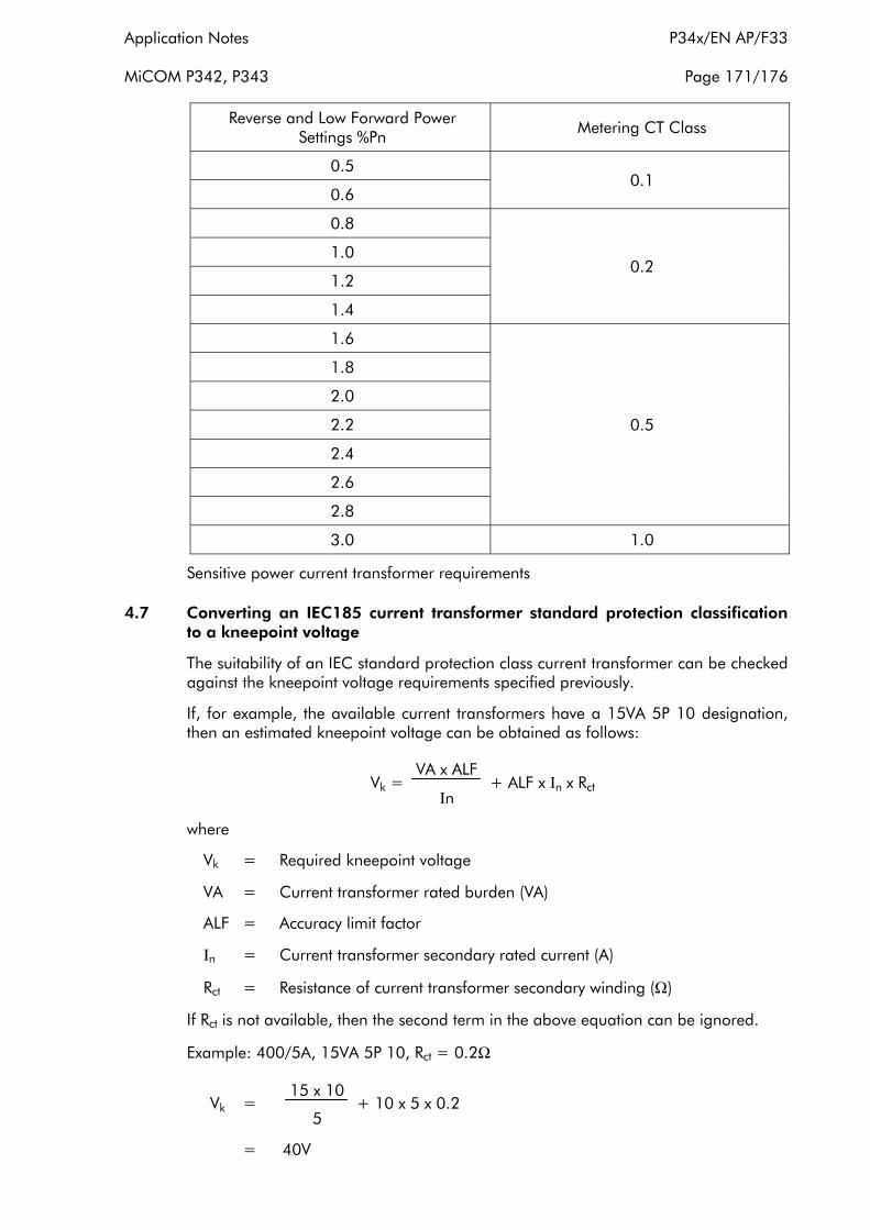
Application Notes P34x/EN AP/F33
MiCOM P342, P343 Page 171/176
Reverse and Low Forward Power Settings %Pn Metering CT Class
0.5 0.1
0.6
0.8
0.2 1.0
1.2
1.4
1.6
0.5
1.8
2.0
2.2
2.4
2.6
2.8
3.0 1.0
Sensitive power current transformer requirements
4.7 Converting an IEC185 current transformer standard protection classification to a kneepoint voltage
The suitability of an IEC standard protection class current transformer can be checked against the kneepoint voltage requirements specified previously.
If, for example, the available current transformers have a 15VA 5P 10 designation, then an estimated kneepoint voltage can be obtained as follows:
VA x ALF Vk = + ALF x Ιn x Rct
Ιn
where
Vk = Required kneepoint voltage
VA = Current transformer rated burden (VA)
ALF = Accuracy limit factor
Ιn = Current transformer secondary rated current (A)
Rct = Resistance of current transformer secondary winding (Ω)
If Rct is not available, then the second term in the above equation can be ignored.
Example: 400/5A, 15VA 5P 10, Rct = 0.2Ω
15 x 10 Vk = + 10 x 5 x 0.2
5
= 40V

P34x/EN AP/F33 Application Notes
Page 172/176 MiCOM P342, P343
4.8 Converting IEC185 current transformer standard protection classification to an ANSI/IEEE standard voltage rating
MiCOM Px40 series protection is compatible with ANSI/IEEE current transformers as specified in the IEEE C57.13 standard. The applicable class for protection is class "C", which specifies a non air-gapped core. The CT design is identical to IEC class P, or British Standard class X, but the rating is specified differently.
The ANSI/IEEE “C” Class standard voltage rating required will be lower than an IEC knee point voltage. This is because the ANSI/IEEE voltage rating is defined in terms of useful output voltage at the terminals of the CT, whereas the IEC knee point voltage includes the voltage drop across the internal resistance of the CT secondary winding added to the useful output. The IEC/BS knee point is also typically 5% higher than the ANSI/IEEE knee point.
Therefore
Vc = [ Vk - Internal voltage drop ] / 1.05
= [ Vk - (In . RCT . ALF) ] / 1.05
Where
Vc = “C” Class standard voltage rating
Vk = IEC Knee point voltage required
Ιn = CT rated current = 5A in USA
RCT = CT secondary winding resistance
(for 5A CTs, the typical resistance is 0.002 ohms/secondary turn)
ALF = The CT accuracy limit factor, the rated dynamic current output of a "C" class CT (Kssc) is always 20 x In
The IEC accuracy limit factor is identical to the 20 times secondary current ANSI/IEEE rating.
Therefore
Vc = [ Vk - (100 . RCT ) ] / 1.05
5. COMMISSIONING TEST MENU
To help minimise the time required to test MiCOM relays the relay provides several test facilities under the ‘COMMISSION TESTS’ menu heading. There are menu cells which allow the status of the opto-isolated inputs, output relay contacts, internal digital data bus (DDB) signals and user-programmable LEDs to be monitored. Additionally there are cells to test the operation of the output contacts and user-programmable LEDs.
The following table shows the relay menu of commissioning tests, including the available setting ranges and factory defaults:

Application Notes P34x/EN AP/F33
MiCOM P342, P343 Page 173/176
Menu Text Default Setting Settings
COMMISSION TESTS
Opto I/P Status - -
Relay O/P Status - -
Test Port Status - -
LED Status - -
Monitor Bit 1 64 (LED 1) 0 to 511
See document P34x/EN GC/E33 for details of digital data bus signals
Monitor Bit 2 65 (LED 2)
Monitor Bit 3 66 (LED 3)
Monitor Bit 4 67 (LED 4)
Monitor Bit 5 68 (LED 5)
Monitor Bit 6 69 (LED 6)
Monitor Bit 7 70 (LED 7)
Monitor Bit 8 71 (LED 8)
Test Mode Disabled Disabled Test Mode Contacts Blocked
Test Pattern All bits set to 0 0 = Not Operated 1 = Operated
Contact Test No Operation No Operation Apply Test Remove Test
Test LEDs No Operation No Operation Apply Test
Table 37
5.1 Opto I/P status
This menu cell displays the status of the relay’s opto-isolated inputs as a binary string, a ‘1’ indicating an energised opto-isolated input and a ‘0’ a de-energised one. If the cursor is moved along the binary numbers the corresponding label text will be displayed for each logic input.
It can be used during commissioning or routine testing to monitor the status of the opto-isolated inputs whilst they are sequentially energised with a suitable dc voltage.
5.2 Relay O/P status
This menu cell displays the status of the digital data bus (DDB) signals that result in energisation of the output relays as a binary string, a ‘1’ indicating an operated state and ‘0’ a non-operated state. If the cursor is moved along the binary numbers the corresponding label text will be displayed for each relay output.
The information displayed can be used during commissioning or routine testing to indicate the status of the output relays when the relay is ‘in service’. Additionally fault finding for output relay damage can be performed by comparing the status of the output contact under investigation with it’s associated bit.

P34x/EN AP/F33 Application Notes
Page 174/176 MiCOM P342, P343
Note: When the ‘Test Mode’ cell is set to ‘Enabled’ this cell will continue to indicate which contacts would operate if the relay was in-service, it does not show the actual status of the output relays.
5.3 Test port status
This menu cell displays the status of the eight digital data bus (DDB) signals that have been allocated in the ‘Monitor Bit’ cells. If the cursor is moved along the binary numbers the corresponding DDB signal text string will be displayed for each monitor bit.
By using this cell with suitable monitor bit settings, the state of the DDB signals can be displayed as various operating conditions or sequences are applied to the relay. Thus the programmable scheme logic can be tested.
As an alternative to using this cell, the optional monitor/download port test box can be plugged into the monitor/download port located behind the bottom access cover. Details of the monitor/download port test box can be found in section 5.10 of this document (P34x/EN AP/E33).
5.4 LED status
The ‘LED Status’ cell is an eight bit binary string that indicates which of the user-programmable LEDs on the relay are illuminated when accessing the relay from a remote location, a ‘1’ indicating a particular LED is lit and a ‘0’ not lit.
5.5 Monitor bits 1 to 8
The eight ‘Monitor Bit’ cells allow the user to select the status of which digital data bus signals can be observed in the ‘Test Port Status’ cell or via the monitor/download port.
Each ‘Monitor Bit’ is set by entering the required digital data bus (DDB) signal number (0 – 511) from the list of available DDB signals in document P34x/EN GC/E33 of this guide. The pins of the monitor/download port used for monitor bits are given in the table overleaf. The signal ground is available on pins 18, 19, 22 and 25.
Monitor Bit 1 2 3 4 5 6 7 8
Monitor/ Download Port Pin 11 12 15 13 20 21 23 24
Table 38
THE MONITOR/DOWNLOAD PORT DOES NOT HAVE ELECTRICAL ISOLATED AGAINST INDUCED VOLTAGES ON THE COMMUNICATIONS CHANNEL. IT SHOULD THEREFORE ONLY BE USED FOR LOCAL COMMUNICATIONS.
5.6 Test mode
This menu cell is used to allow secondary injection testing to be performed on the relay without operation of the trip contacts. It also enables a facility to directly test the output contacts by applying menu controlled test signals. To select test mode this cell should be set to ‘Enabled’ which takes the relay out of service causing an alarm condition to be recorded and the yellow ‘Out of Service’ LED to illuminate. Once testing is complete the cell must be set back to ‘Disabled’ to restore the relay back to service.

Application Notes P34x/EN AP/F33
MiCOM P342, P343 Page 175/176
WHEN THE ‘TEST MODE’ CELL IS SET TO ‘ENABLED’ THE RELAY SCHEME LOGIC DOES NOT DRIVE THE OUTPUT RELAYS AND HENCE THE PROTECTION WILL NOT TRIP THE ASSOCIATED CIRCUIT BREAKER IF A FAULT OCCURS.
HOWEVER, THE COMMUNICATIONS CHANNELS WITH REMOTE RELAYS REMAIN ACTIVE WHICH, IF SUITABLE PRECAUTIONS ARE NOT TAKEN, COULD LEAD TO THE REMOTE ENDS TRIPPING WHEN CURRENT TRANSFORMERS ARE ISOLATED OR INJECTION TESTS ARE PERFORMED.
5.7 Test pattern
The ‘Test Pattern’ cell is used to select the output relay contacts that will be tested when the ‘Contact Test’ cell is set to ‘Apply Test’. The cell has a binary string with one bit for each user-configurable output contact which can be set to ‘1’ to operate the output under test conditions and ‘0’ to not operate it.
5.8 Contact test
When the ‘Apply Test’ command in this cell is issued the contacts set for operation (set to ‘1’) in the ‘Test Pattern’ cell change state. After the test has been applied the command text on the LCD will change to ‘No Operation’ and the contacts will remain in the Test State until reset issuing the ‘Remove Test’ command. The command text on the LCD will again revert to ‘No Operation’ after the ‘Remove Test’ command has been issued.
Note: When the ‘Test Mode’ cell is set to ‘Enabled’ the ‘Relay O/P Status’ cell does not show the current status of the output relays and hence can not be used to confirm operation of the output relays. Therefore it will be necessary to monitor the state of each contact in turn.
5.9 Test LEDs
When the ‘Apply Test’ command in this cell is issued the eight user-programmable LEDs will illuminate for approximately 2 seconds before they extinguish and the command text on the LCD reverts to ‘No Operation’.
5.10 Using a monitor/download port test box
A monitor/download port test box containing 8 LED’s and a switchable audible indicator is available from AREVA T&D, or one of their regional sales offices. It is housed in a small plastic box with a 25-pin male D-connector that plugs directly into the relay’s monitor/download port. There is also a 25-pin female D-connector which allows other connections to be made to the monitor/download port whilst the monitor/download port test box is in place.
Each LED corresponds to one of the monitor bit pins on the monitor/download port with ‘Monitor Bit 1’ being on the left hand side when viewing from the front of the relay. The audible indicator can either be selected to sound if a voltage appears any of the eight monitor pins or remain silent so that indication of state is by LED alone.

P34x/EN AP/F33 Application Notes
Page 176/176 MiCOM P342, P343